USER S MANUAL. SCHNITZEL PRESS SP 250 Rev 05/ SP 400 Rev 05 SELO ORDER NUMBER SELO B.V. Postbus AP Oldenzaal, The Netherlands
|
|
|
- Ronald Parker
- 6 years ago
- Views:
Transcription
 541 58 20 00 Fax: (31) 541 52 15 95 E-mail: info@selo.")
1 USER S MANUAL SP 250 Rev 05/ SP 400 Rev 05 SELO ORDER NUMBER SELO B.V. Postbus 357 NL-7570 AJ Oldenzaal, The Netherlands Tel: (31) Fax: (31) info@selo.com Website DB Visitor s address: Eektestraat AP Oldenzaal, The Netherlands Date: January 2005
2 Copyright B.V., The Netherlands, 2006 All rights reserved. All technical and technological information included in this manual, as well as any drawings and technical descriptions made available by us, are the property of B.V. and may not be copied, reproduced or in any way made available to third parties without our prior express written permission. If there are data cited in this manual that deviate from that stated in one or more written agreement(s) concluded with B.V., then that written in this (these) agreement(s) is of overriding importance. In addition, B.V. reserves the right to revise this publication and implement modifications to the content over certain periods of time without the obligation to give advance notice of such a revision or modification. In spite of all the care taken in the composition of this user's manual, B.V. can accept no liability for any damage, which may be the result of any error, which may appear in this user s manual. No rights can be derived from the text of this user s manual. Should you encounter any imperfection in the text, we would be very appreciative if you were to communicate this to us. Suggestions on how to improve this user s manual are also more than welcome. B.V. 2
3 Foreword I How to use this manual This manual is designed to help you use and maintain the Schnitzel press in a safe way. The manual has been compiled for users of the FMS Mixer. The manual is divided into eight chapters and also includes tables, drawings, diagrams, explanatory notes and a number of appendices, to give you easy access to the information you are looking for. Foreword Contains information on how to use this manual. Contents Contains a numbered list of all of the chapters and sections of this manual. Chapter 1 Introduction Contains general information regarding the Schnitzel press, describes how the system works and sets out the requirements that apply to the conditions of use and the qualification requirements that apply to the personnel responsible for operating the machine. Chapter 2 Safety Describes the most significant safety risks, the safety devices installed in the machine, the safety precautions that need to be observed and the meaning of the symbols displayed on the Schnitzel press. Chapter 3 Transport and storage Chapter 4 Installation and connecting up the machine Describes how to install and connect up the Schnitzel press and the procedures to be followed in programming the settings of the machine. Chapter 5 Operating Explains how to operate the machine and how to solve any problems that may be encountered. Chapter 6 Cleaning and maintenance Appendices Contain additional information and forms and checklists for inspection and control. II Notation of important points Certain parts of the text of this manual call for special attention. These parts of the text are indicated as follows: Tip : Gives the user suggestions and advice on how certain tasks can be carried out more easily or more efficiently. Please note! A comment that provides important additional information, alerting the user to possible problems. Warning : Important points to be observed. In failing to observe these warnings the user may sustain (serious) injury or cause serious damage to the product. B.V. 3
4 Table of contents CHAPTER 1 INTRODUCTION PRODUCT DESCRIPTION DESCRIPTION OF MAIN COMPONENTS PURPOSE OPERATING CONDITIONS OPERATOR REQUIREMENTS CONTROLS...7 CHAPTER 2 SAFETY INTRODUCTION SAFETY AND HEALTH RISKS SAFETY DEVICES SAFETY MEASURES TO BE TAKEN INTO ACCOUNT SAFETY MEASURES DURING OPERATION...11 CHAPTER 3 TRANSPORT AND STORAGE TRANSPORT STORAGE...12 CHAPTER 4 INSTALLATION AND START-UP INTRODUCTION INSTALLATION...13 CHAPTER 5 OPERATION INTRODUCTION OPERATION SETTINGS OPERATING THE OPERATION FAILURES...17 CHAPTER 6 CLEANING AND MAINTENANCE INTRODUCTION CLEANING INSPECTION...20 B.V. 4
5 CHAPTER 1 INTRODUCTION The Schnitzel Press is a machine for pressing veal, beef, pork or poultry. Product examples: schnitzels, meat rolls, braising steak, chicken fillet, turkey, meat. The pressing action is established by a combination of two specially profiled belts (rep 218/275), one on top of the other. The belts are driven independently of each other. The machine is equipped with a continuous thickness adjuster. The pieces of meat should be placed manually onto the feed section of the machine. The feed side is protected by a protective cover with proximity switch. The machine is operated by means of switches on the control panel. The machine is made of stainless steel for as much as is possible. The belts are coated with white Nomex 65 PVC. (Meet the FDA requirements.) 1.1 Product description A A. Schnitzel press B. rolling undercarriage C. switch box with control panel C B Figure 0.1 Overview of main components B.V. 5
6 1.2 Description of main components SWITCH BOX of the schnitzel press The switch box is fitted with equipment for switching the motors. This equipment consists of the following parts: Contactors; Transformer; Thermal safety device control current 2A; Thermal motor safety switch; Phase-sequence monitoring; Three push buttons for starting/stopping/reversing the belt Warning light Three contact plugs The switch box s stop button also serves as an emergency stop. Electrical installation The schnitzel press s switch box is fitted with two circuits. 1. Main electrical circuit 400V (see appendix C). 2. Control current circuit 24V (see appendix C). Electrical circuit The main electrical circuit and control current circuit are illustrated in appendix C. Transport belts Description: Nonex 65 PVC coating. Please note the arrow indicating the correct feed direction of the belts when (re)assembling them (this arrow is printed on the inside of the belt(s)). Warning: Please follow the instructions in Chapter 6 Cleaning and Maintenance when assembling a new belt. Motor reductor 400 V For type SP 250 Rev 05: Electromotor 27 rpm, 0.15 kw, 3 phase, 50 Hz, 0.6 A, see type plate. For type SP 400 Rev 05: Electromotor 25 rpm, 0.37 kw, 3 phase, 50 Hz, 1.24 A, see type plate. Switches Mechanically forced type. All the technical specifications of the schnitzel press are included in appendix A of this user s manual. Contactor Mechanically forced type. All the technical specifications of the schnitzel press are included in appendix A of this user s manual. 1.3 Purpose The schnitzel press may only be used for pressing veal, beef, pork or poultry. Product examples: schnitzels, meat rolls, braising steak, chicken fillet, turkey, meat. The schnitzel press should not be used for other purposes. 1.4 Operating conditions The schnitzel press may only be used under the following operating conditions. The schnitzel press should be placed on a solid, level surface. The schnitzel press should be stable and level. Before operating the schnitzel press, the brake of the swivelling wheels (if the undercarriage is supplied) should be secured. B.V. 6
7 1.5 Operator requirements The schnitzel press may only be used by people that have been instructed and are familiar with its operation. Warning: B.V. recommends the use of safety shoes with antiskid soles for all actions performed to the schnitzel press. 1.6 Controls The schnitzel press is controlled using push buttons installed on the switch box. The control panel and controls are illustrated in figure 1.2; the functions relating to the buttons are outlined in table B.V. 7

8 Figure 1.2 Controls Item Description Item Description 1 Removable protective cover 16 Locking/unlocking upper belt/ thickness adjustment cam 2 Removable protective cover 17 Handle for tipping upper belt 3 Protective motor cover 18 Upper belt scraper 4 Protective motor cover 19 Feed belt scraper 5 Undercarriage 20 Switch box 6 Frame wheel 21 24V socket, feed valve safety 7 Swivelling wheel V socket, power supply for drive motors 8 Upper belt tipping fastener 23 Warning light Machine is live 9 Unlocking handle for upper belt tipping 24 Start button position 10 Hand wheel for upper belt thickness 25 Stop button adjustment / tipping position 11 Lower belt tightening lever 26 Reverse key switch 12 Upper belt tightening lever 13 Safety feed valve 14 Safety contactor 15 Feed belt B.V. 8
9 Table 1.1 Control functions Control Push button Start Push button Stop Push button Reverse Safety contactor Function The schnitzel press is activated, the transport belts are starting. The schnitzel press stops immediately. The Reverse switch should be used in combination with the start button so as to move the belts into the opposite direction. (This operation is only possible when the start button and the reverse button are operated simultaneously.) Function tip: the belts reverse 2 cm per button push The schnitzel press s power supply is interrupted. The machine stops as soon as the safety feed valve is opened. Attention: When the safety feed valve of the schnitzel press is opened, the machine stops. You should push the 'Start' button again so as to complete the operation; the machine will start again. Machine type plate B.V. 9
10 CHAPTER Introduction SAFETY This chapter outlines all safety aspects. It is of the utmost importance that everyone operating the schnitzel press is informed on the contents of this chapter. Tip: If the safety aspects are not clear to you, please ask the manufacturer for more information. The main safety and health risks related to the schnitzel press are outlined in paragraph 2.2. Paragraph 2.3 then describes the safety devices that have been installed on the schnitzel press. Furthermore, paragraph 2.4 states the safety measure that should be considered by the operator of the schnitzel press. 2.2 Safety and health risks The following safety and health risks should be taken into account for the schnitzel press (the numbers refer to the paragraphs in this manual explaining the mentioned risks): Decreased stability of the machine caused by incorrect installation , 3.2 Direct or indirect electrical contact , 2.3.3, 4.2, 6.2 Correct or incorrect securing of the wheel blocking Malfunction of one of the switches Damage to the cables or connectors Detaching of the protective covers and/or screen covers from the schnitzel press (during transport)3.2 Reversion of the top part caused by an incorrect action / installation Hands getting stuck between feed valve and transport belt Chance of blisters when touching the belt at the scrapers (conveyance side) The designers of the schnitzel press were aiming at reducing these risks as much as possible; the safety devices for this purpose are listed in paragraph 2.3. In order to protect himself against the remaining risks, the operator of the schnitzel press should take the required safety measure into account. These are listed in paragraph Safety devices The following safety devices have been installed so as to make the operation of the schnitzel press as safe as possible. The schnitzel press is fitted with a stop button and safety contactor for stopping the machine immediately in case of emergency. The electromotors are thermally protected, preventing overheating. A safety valve with safety contactor is mounted above the feed belt. The schnitzel press stops immediately when the safety valve is pushed upwards. The safety contactor and 'stop' button can also be used together as an emergency stop. 2.4 Safety measures to be taken into account A number of safety measures should be taken into account in view of a safe operation of the schnitzel press. B.V. 10
11 Personal protection B.V. advises the use of safety shoes and antiskid soles while operating the schnitzel press. Safety precautions: Make sure that the operation, small maintenance jobs and actions for installing, constructing or moving the schnitzel press are only performed by qualified personnel, i.e. personnel that is competent and familiar with the contents of this manual. Make sure that the schnitzel press is installed correctly and in a stable way. Check whether the voltage source complies with the local regulations. The connection and the circuit in the schnitzel press are performed by a safety earth. Make sure you have the correct earth connection. Use earthed leads and extension leads having a diameter that is large enough and a voltage source equipped with an earth leakage circuit breaker. Make sure that the wall socket and any connections between the extension leads are well protected against humidity. Do not pull the plug out of the wall socket or extension lead by the lead. 2.5 Safety measures during operation Warning: Never operate the schnitzel press when the switch box and/or connections are wet. Attention! : Remove the reverse key from the schnitzel press and keep it in a safe place. Warning: Be careful when placing meat on the feed belt. Make sure that your hands do not get stuck between the feed belt and the feed valve. Warning: Watch out for the scrapers at the conveyance side on the feed belt when handling pressed meat. Make sure that your hands do not touch the belt and/or scrapers. Keep the space around the schnitzel press free of materials and other obstacles. Do not put any loose tools or objects on the schnitzel press or switch box. These can end up or fall between moving parts. If you leave the schnitzel press unattended, the power supply should be disconnected from the switch box. Safety measures during inspection, cleaning and maintenance Make sure that maintenance and repair works should only be performed by expert and skilled people. This type of work may only be performed when the schnitzel press is switched off. Make sure that the power is disconnected when opening the switch box and during maintenance. Measures for keeping the schnitzel press in good condition Make sure that the schnitzel press is always in good condition. When the schnitzel press is used at regular intervals, it should be checked at least once a year. Pay special attention to the electric cables, which may not be damaged, and the belts, which should be in good condition, and the correct functioning of the operation. B.V. 11
12 CHAPTER Transport TRANSPORT AND STORAGE When the schnitzel press is transported the rolling undercarriage and the schnitzel press must be transported separately. Protective and security covers must be attached to the machine. Transport in the production area In the production area, the schnitzel press can be transported on the rolling undercarriage that is especially for that purpose. 3.2 Storage Perform the following actions before storing the schnitzel press: Before storing the schnitzel press, perform a general check-up. Check all the vital parts: - Safety contactor; - Switches; - Switch box; - Wheels. If necessary, replace the damaged parts. Before storage, the schnitzel press must be cleaned. Place the schnitzel press on a level and stable surface. Secure the wheels. B.V. 12
13 CHAPTER Introduction INSTALLATION AND START-UP This chapter describes how the schnitzel press should be prepared for operation. Paragraph 4.2 discusses the basic operations for the installation. The required settings are described in paragraph 4.3. In conclusion, paragraph 4.4 indicates which checks must be performed before the schnitzel press may be operated. 4.2 Installation Make sure that the following regulations are met before connecting the electric power: - The voltage source meets the local regulations; - You have a correct earth connection; - The used extension cords are earthed and have a sufficient Warning: diameter; - The voltage source is provided with an earth leakage circuit breaker; - The wall socket and any connections between the extension cords are well protected against humidity. 1. Place the schnitzel press on a level and stable surface which is free of materials. 2. Secure the wheels of the rolling undercarriage (if the undercarriage has been supplied). 3. Set the thickness adjustment of the machine. A set of adjusting tools has been supplied in the packing of the switch box. This set contains two bars with an end piece of 12 mm and two blocks of 8 mm thick. Warning: When mounting a new switch box or a switch box of another schnitzel press, the rotation direction must first be checked. A phase-sequence control is installed in the new switch boxes. So before using the schnitzel press, check the rotation direction of the belts! B.V. 13


14 13,5 Turn the hand wheel to create the required distance between the upper and lower belt. Place the calibres as shown. (Place the 12 mm calibres between the first two small rollers) Place the 8 mm calibres between the two large rollers on the conveyance side. Lower the upper belt by turning the height adjusting hand wheel. Stop as soon as the rollers have contact with the first calibres. Loosen the fixing screws of the upper belt so the top part touches the four calibres. Turn the thickness adjustment hand wheel to Secure the fixing screws. Turn the hand wheel to the right (up) and remove the calibres. B.V. 14
. 6. If necessary, adjust the scrapers of the upper and lower belt.")
15 4. Place the switch box on top of the schnitzel press (between the two handles of the safety lid of the upper belt). 5. Connect the plugs of the schnitzel press to the switch box (the two red plugs can be exchanged). 6. If necessary, adjust the scrapers of the upper and lower belt. The schnitzel press is now ready for use. See chapter 5 operation for more information on the operation of the schnitzel press. B.V. 15

16 CHAPTER Introduction OPERATION The actual operation of the schnitzel press is very easy. It is, however, very important to take all the safety regulations into account when working with the schnitzel press. The first part of this chapter is dedicated to the operational actions that must be performed on the schnitzel press, followed by a discussion of the possible failures, causes thereof and solutions for repairing the failures. 5.2 Operation The pressing action is established by a combination of two specially profiled belts, one on top of the other. The belts are driven independently of each other. The machine is equipped with a continuous thickness adjuster. The pieces of meat should be placed manually onto the feed section of the machine. The feed side is protected by a protective cover with safety contactor. The machine is operated by means of switches on the control panel. 5.3 Settings When the schnitzel press is used for the first time, the instructions of chapter 4 'Installation and startup' should be followed strictly. When all the plugs of the switch box are connected, connect the plug of the switch box to the wall socket. The light of the switch box will then be switched on. (The switch box is live, the schnitzel press is now ready for use.) 5.4 Operating the schnitzel press Thickness adjustment: When the hand wheel is turned to the right, the distance between the two belts increases. (in the end position, the upper part can be tilted, the thickness indication is approximately 15) Before operating the schnitzel press, make sure that the area around the schnitzel press is free from obstacles. The schnitzel press is operated with push buttons that are mounted on the switch box. If the Start button is pressed, the belts will start running. If the Stop button is pressed, the belts will stop. If the reverse switch is operated with the matching key and is kept on position [I] while you press the start button, the belts will run in the opposite direction (2cm each time). If the stop button is pressed, the schnitzel press stops immediately. B.V. 16
17 5.5 Operation failures Practice has shown that approximately 95% of the failures are not in the switch box. So first of all look for the failures outside of the switch box and check the fuses and automatic parts in the building terminal box, the voltage of the main power circuit and the thermal magnetic motor protection switch in the switch box. In any case, check the fuses, the end switches and the wiring outside of the switch box. In table 5.1 you can find an overview of failures, matching causes and actions to repair the failures. B.V. 17
18 Table 5.1 List of failures Observation Possible cause Action Machine does not start up Machine does not start up and the light of the switch box is off. Motor is not running, is humming or is becoming exceptionally hot. motor is not running, is humming or is becoming exceptionally hot. A cracking sound comes from the reductor when switching the motor on and off. motor is not running, is humming or is becoming exceptionally hot. A stinking sickly smell comes from the motor. motor becomes extremely hot. thermal safety 2A is switched off The plug of the supply cable is not plugged in Plug(s) of motor cable of upper and lower belt not plugged in on the switch box. Safety feed valve 227 is up which means that the safety contactor is interrupting the supply Plug of the cable contactor is not plugged in on the switch box. Phases of the supply cable have been connected incorrectly Error in the main electrical circuit. the gear wheels in the reductor are broken. the motor is entirely or partly burnt. One or two windings of the motor have stopped working properly. The motor is burnt for approx. 40%. Also see: stinking smell comes from motor. Short circuit in the control current circuit. check the extension cord, plugs, contactors and motors. After that, switch the thermal motor protection switch back on manually. Repair. Close valve. Repair. Contact Service for correctly wiring the switch box ATTENTION! Make sure that the machine is not live when you are performing the measurements. Use a volt meter to check the main electrical circuit including the fuses in the switch box of the structure, the extension cord, the plugs in the thermal motor protection switch in the switch box of the schnitzel press or until the connection to the motor. Check if the wiring is fixed well. Contact Service B.V. Contact Service B.V. Contact Service B.V. ATTENTION! Make sure that the machine is not live when you are performing the measurements. Check if the wiring is fixed well. Check the transformer and the coils of the contactors. If the schnitzel press shows a failure which is not included in table 5.1 or which you cannot repair by means of this table, please contact Service B.V. B.V. 18

19 CHAPTER Introduction CLEANING AND MAINTENANCE The schnitzel press is designed and constructed in such a way that maintenance can be reduced to a minimum. There are no lubrication points on the schnitzel press and all the bearings in the drive and motor unit are self-lubricating. However, make sure that no hard materials, dust or dirt gets between the turning parts; keep the schnitzel press clean and tidy. Warning: Maintenance and repair works must be performed by expert and competent people, preferably qualified engineers of the manufacturer or from your own technical service. 6.2 Cleaning Warning: Switch off the main power supply. 1. Remove the plugs from the switch box. 2. Disconnect the control panel and put it in a dry place. 3. The height of the adjustment cams can be adjusted with the hand wheel on the feed side. 4. When the wire pot with indicator reaches the front position, the top part is free of the height adjustment brackets. 5. You can tip over the upper part of the machine using the two handles located on the front of the schnitzel press. Warning: When tipping over the upper belt, you should use the two handles (figure 1.2 rep 17), lift the upper part until the bolting handle locks. By lifting the upper part slightly and holding the lever up, you can slowly lower the upper part. 6. Both conveyers will slacken by pulling the tightening levers. 7. Disassemble the scrapers and remove the belts. B.V. 19


20 Warning: When the machine is cleaned with a high-pressure cleaner, the plugs and motors may not be sprayed. Make sure that the removable protective motor covers are present. Warning: When mounting a new belt, the tension and position of the scraper must be adjusted and the belt must run straight. That can be done with the adjustment bolts on the feed and conveyance side. B1 A1 A2 B2 Adjustment of the tension and making sure that the upper belt is running straight on the feed and conveyance side A1, A2: Adjusting screws on the feed side, upper belt B1, B2: Adjusting screws on the feed side, lower belt Conveyance side: Attention! First unscrew the fixing bolts. * C1, C2: Adjusting screws on the conveyance side, upper belt D1, D2: Adjusting screws on the conveyance side, lower belt D1 C1 * * * * C2 D2 6.3 Inspection Monthly During the weekly inspection, pay extra attention to the following points: The electrical insulation; Correct functioning of the switches; Correct functioning of the control tools. B.V. 20
21 Appendices B.V. 21
22 Appendix A Product specifications SELO Type 250 Rev 05 Type 400 Rev 05 Specifications supply belt Belt width : 250 mm 400 mm Weight : 205 kg 300 kg Height : Electrical specifications Electrical connections : 400 V. 50 Hz 3 ph 400 V. 50 Hz 3 ph Number of motors : 2 2 Power : 2 x 0,15 kw, 0,65A 2 x 0,37 kw, 1,3A Electrical box with magnetic switches, transformer (primary 400 V, secondary 24 V), thermal-magnetic motor safety switch, phase-sequence safety relay. B.V. 22
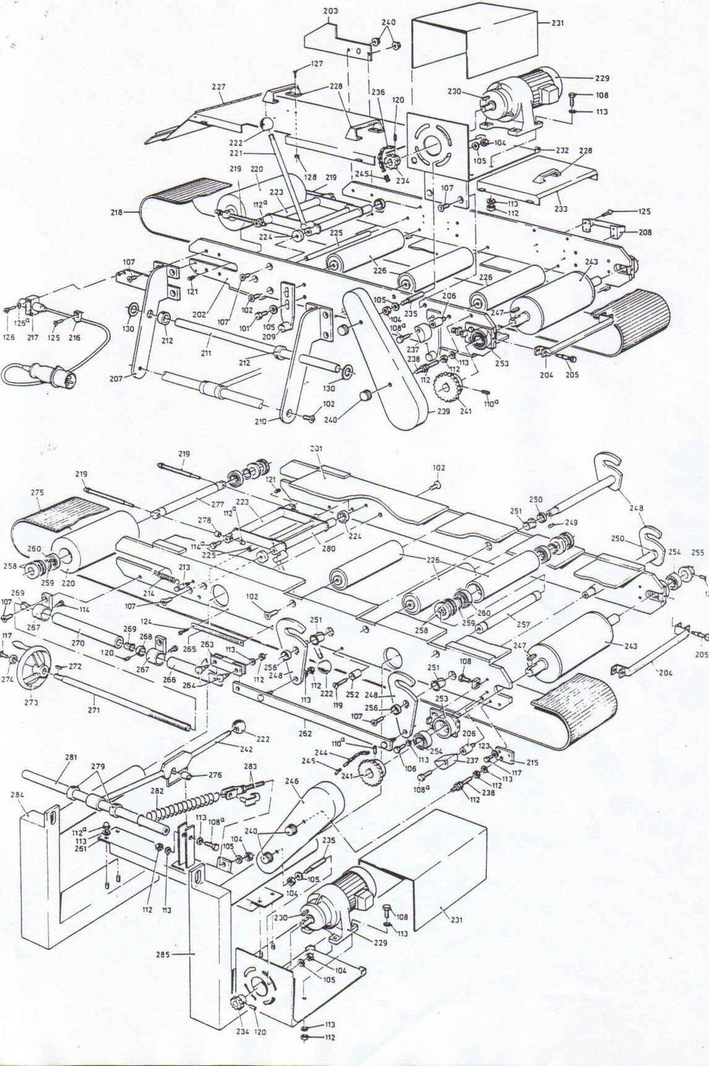
23 Appendix B Spare parts Ref. Description GB 82 Cable 83 contact box for driving connection 84 contact box for driving connection 85 contact box for connection magnet safety sensor 86 Controle lamp red 87 push-button Start 88 push-button Stop 89 push-button Reverse 300 K.M. Zoo-1,6 Thermical protection 301 Ceeform type 1467 Contact box 302 Werco 400V-24A 50VA Transformer 303 Rafi Signal lamp 304 Rafi Fuse 305 K.M. RP-RTX push-button K.M. 110 T push-button K.M. BE 3 push-button K.M. EK 01 push-button 306 K.M. RD-X push-button K.M.111 T push-button K.M. BE3 push-button K.M. EK 10 push-button 307 K.M. RS-KMS1 push-button ( with lock ) K.M. BE3 push-button K.M. EK 01 push-button K.M. EK 10 push-button 308 Effector type IA-2010-ABOA Proximity switch 309 Gruner Rel. 682 Relay Gruner ZKR 088 Relay Montage clip Montage clip 310 K.M. DIL OOM-10 Magnetic switch 311 CEEFORM TYPE 1463 Contact box for connection proximity switch 201 S.P Upper Frame 202 S.P Lower Frame 203 S.P Safety plate 204 S.P Scraper 205 S.P Fastener bolt 206 S.P Fastener shaft 207 S.P Tipping support B.V. 23
24 Ref. Description GB 208 S.P Grip 209 S.P Adjusting plate 210 S.P Tipping support 211 S.P Shaft 212 S.P Adjusting ring 213 S.P Spring tightening 214 S.P Spring 215 S.P Fastener plate 216 S.P Cable clamp 217 S.P Proximity switch 218 S.P Belt 219 S.P screw stud 220 S.P Idler Roller 221 S.P Tightening device 222 S.P Spherical knob 223 S.P Shaft 224 S.P bus 225 S.P Shaft 226 S.P Pressure roller 227 S.P Safety cover B.V. 24
25 B.V. 25
26 APPENDIX C ELECTRICAL DRAWING B.V. 26
OLYMPIAN MODEL 740 Operation and Service Manual
 OLYMPIAN MODEL 740 Operation and Service Manual P/N 133911-102 FCI MANUAL P/N 133865-001 Data herein has been verified and validated and believed adequate for the intended use. If the machine or procedures
FTFR Maintenance and Parts Manual SQ-1 FLOOR TRUSS FINISH ROLLER. Operators Manual
 FTFR Maintenance and Parts Manual SQ-1 FLOOR TRUSS FINISH ROLLER Operators Manual FOREWORD This manual explains the proper maintenance of Square 1 Design Floor Truss Finish Roller as well as the daily
ABACO MACHINES OPERATION MANUAL STONE/STEEL/GLASS/WOODS LIFTER (ASSGWL20) ABACO MACHINES (USA)
 ABACO MACHINES (USA)") ABACO MACHINES OPERATION MANUAL STONE/STEEL/GLASS/WOODS LIFTER (ASSGWL20) ABACO MACHINES (USA) 14508 S. Garfield Ave., Paramount, CA 90723, USA Tel : 310-532-0366 Fax : 310-532-99 Email : sales@abacomachines.com
ABACO MACHINES OPERATION MANUAL STONE/STEEL/GLASS/WOODS LIFTER (ASSGWL20) ABACO MACHINES (USA) 14508 S. Garfield Ave., Paramount, CA 90723, USA Tel : 310-532-0366 Fax : 310-532-99 Email : sales@abacomachines.com
XPS-ProFeed Shuttle SERVICE MANUAL. Revised:
 XPS-ProFeed Shuttle SERVICE MANUAL Revised: 1-14-15 RENA SYSTEMS INC. 910 East Main Street; Suite 200 Norristown, PA 19401-4110 Phone: (610) 650-9170 Fax: (610) 270-3947 Web Site: www.renausa.com SAFETY
User manual for Exalto windshield wiper Type 233 BD 12/24 Volt. Cat.no /32/35/40/45/50 (12 Volt) Cat.no /32/35/40/45/50 (24 Volt)
 Cat.no /32/35/40/45/50 (24 Volt)") Q u alit y Marine E quip Parts Wipers Bearings Propulsion User manual for Exalto windshield wiper Type 233 BD 12/24 Volt Postbus Q 40 u ality Marine E quipment 3370 AA Hardinxveld-Giessendam Nederland
Q u alit y Marine E quip Parts Wipers Bearings Propulsion User manual for Exalto windshield wiper Type 233 BD 12/24 Volt Postbus Q 40 u ality Marine E quipment 3370 AA Hardinxveld-Giessendam Nederland
XPS-ProFeed Shuttle SERVICE MANUAL. Revised:
 XPS-ProFeed Shuttle SERVICE MANUAL Revised: 9-14-15 RENA SYSTEMS INC. 910 East Main Street; Suite 200 Norristown, PA 19401-4110 Phone: (610) 650-9170 Fax: (610) 270-3947 Web Site: www.renausa.com SAFETY
User manual for Exalto windshield wiper Type 223 BS 12/24 Volt
 Q u alit y Marine E quip Parts Wipers Bearings Propulsion User manual for Exalto windshield wiper Type 223 BS 12/24 Volt Cat. no. 2167.30/35 (12 Volt) Cat. no. 2168.30/35 (24 Volt) version 9-2012 Safety
ABACO GLASS LIFTER (AGL38)
") ABACO MACHINES ABACO GLASS LIFTER (AGL38) ABACO MACHINES (USA) 14508 S. Garfield Ave., Paramount, CA 90723, USA Tel : 310-532-0366 Fax : 310-532-0499 Email : sales@abacomachines.com Website : www.abacomachines.com
ABACO MACHINES ABACO GLASS LIFTER (AGL38) ABACO MACHINES (USA) 14508 S. Garfield Ave., Paramount, CA 90723, USA Tel : 310-532-0366 Fax : 310-532-0499 Email : sales@abacomachines.com Website : www.abacomachines.com
User manual for. Exalto windshield wiper Type 223 BD 12/24 Volt
 User manual for Parts Wipers Propulsion Exalto windshield wiper Type 223 BD 12/24 Volt Catalogue no. 2165.30/32/35/40 (12 Volt) Catalogue no. 2166.3032/35/40 (24 Volt) version 6-2007 Copyright 2007: Exalto
OPERATING AND MAINTENANCE INSTRUCTIONS HYDRAULIC ELECTRICAL PUMPS HAM (Manual control) HAE (Electrical control)
 HAE (Electrical control)") OPERATING AND MAINTENANCE INSTRUCTIONS HYDRAULIC ELECTRICAL PUMPS HAM (Manual control) HAE (Electrical control) Part Nr : HA M 4 6 2 1 B C 1. Essential safety requirements. 2. Technical Characteristics.
OPERATING AND MAINTENANCE INSTRUCTIONS HYDRAULIC ELECTRICAL PUMPS HAM (Manual control) HAE (Electrical control) Part Nr : HA M 4 6 2 1 B C 1. Essential safety requirements. 2. Technical Characteristics.
PHASE CONVERTERS OPERATING & MAINTENANCE INSTRUCTIONS. MODEL NO: PC40 and PC60. PART Nos:
 PHASE CONVERTERS MODEL NO: PC40 and PC60 MODEL PART No: NO: 6012805 PC20 and PC40 6012810 PC60 PART Nos: 6012800 6012805 6012810 OPERATING & MAINTENANCE INSTRUCTIONS 0107 Specifications PC20 PC40 PC60
These operating instructions apply for: NCX 380 NCZ 300 NCX 480 NCZ 370 NCX 580 L NCZ 480 NCX 660 K NCZ 560 NCZ 660 NCZ 800
 Original instructions Operating Instructions for May 2010 Electric Internal Vibrators BA No. 1092E Series NCX and NCZ These operating instructions apply for: NCX 380 NCZ 300 NCX 480 NCZ 370 NCX 580 L NCZ
Drive Unit e-drive1. Installation instructions 04/2014. English translation of the original German installation instructions
 Drive Unit e-drive1 Installation instructions 04/2014 English translation of the original German installation instructions Contents Foreword... 3 Availability... 3 Structural features in the text... 3
PrioVino Premier. Translation of Original Operating Instructions. Status: August First edition January 2018 / PrioVino GmbH
 PrioVino Premier Translation of Original Operating Instructions Status: August 2018 First edition January 2018 / PrioVino GmbH Reprint even in extracts only upon written permission by PrioVino GmbH (ISO
Technical Manual Electrical Power Supply System T4002
 Technical Manual Electrical Power Supply System T400 MOZELT GmbH & Co. KG Please observe the following safety information and recommendations before start-up! Copyright: MOZELT GmbH & Co. KG, D-4769 Duisburg
SERVICE MANUAL USA. Hot Island 48-2 level
 SERVICE MANUAL Hot Island 48-2 level - NOTICE - This manual is prepared for the use of trained Service Technicians and should not be used by those not properly qualified. If you have attended a training
Mounting Tools 2 Checking Clearances 3 Components 4-5 Mounting 6-21 Correct Method of Tensioning the Chain 22 Adjusting The Overall Dimension 23-24
 Mounting Tools 2 Checking Clearances 3 Components 4-5 Mounting 6-21 Correct Method of Tensioning the Chain 22 Adjusting The Overall Dimension 23-24 Maintenance 25 Repairing Main Body Patterns 26 Removal
Armon Edero. User manual
 User manual Armon Edero Foreword.... 2 Symbols used 2 Intended use.... 2 About the Armon Edero... 2 Mounting options of the Edero 2 Braces. 3 How to set up the Armon Edero.. 3 How to attach the brace to
High Frequency SineWave Guardian TM
 High Frequency SineWave Guardian TM 380V 480V INSTALLATION GUIDE FORM: SHF-IG-E REL. January 2018 REV. 002 2018 MTE Corporation High Voltage! Only a qualified electrician can carry out the electrical installation
Reproduction or other use of this Manual, without the express written consent of Vulcan, is prohibited.
 SERVICE MANUAL ELECTRIC BRAISING PANS (30 & 40 GALLON) VE30 VE40 ML-126849 ML-126850 VE40 SHOWN - NOTICE - This Manual is prepared for the use of trained Vulcan Service Technicians and should not be used
OPERATING AND MAINTENANCE MANUAL. Primary Current Injection Test Set. 750ADM-H mk2
 OPERATING AND MAINTENANCE MANUAL Product: Type: Primary Current Injection Test Set 750ADM mk2 750ADM-H mk2 DESIGNED AND MANUFACTURED BY: T & R Test Equipment Limited 15-16 Woodbridge Meadows, Guildford,
Installation and Operation Manual
 1645 Lemonwood Dr. Santa Paula, CA 93060 USA Toll Free: 1 (800) 253-2363 Tel: 1 (805) 933-9970 rangerproducts.com Ranger Floor Jack Installation and Operation Manual Manual Revision B July 2017 Manual
INSTRUCTION MANUAL MAGNA RAIL
 R ENGLISH NR. 148293 00 INSTRUCTION MANUAL MAGNA RAIL 1999-05-01 List of contents Declaration of conformity, CE Delivery check Mounting instruction (rail, trolley units) Mounting instruction (exhaust pipe,
Assembly instructions PRORUNNER mk1 2
 Assembly instructions PRORUNNER mk1 Version 0.1 / 01-JUN-2013 Copyright Qimarox B.V. All rights reserved. No part of this document may be copied, stored in a database and/or published by means of printing,
Installation, Service and Parts List Series 56,800 for Class I & II, Division 2 Manual Adjust Brakes
 Spring-Set Disc Brakes P/N 8-078-905-8 effective /0/0 Installation, Service and Parts List Series 56,800 for Class I & II, Division Manual Adjust Brakes Tools required for installation and servicing: /8
Vertical Stacking System for both Floor and Roof Lines. SQ-1 INTELLIGENT STACKERS. Operators Manual
 Vertical Stacking System for both Floor and Roof Lines. SQ-1 INTELLIGENT STACKERS Operators Manual FOREWORD This manual explains the proper maintenance of Square 1 Design Intelligent Stacking System as
Printed: Doc-Nr: PUB / / 000 / 00
 ORIGINAL OPERATING INSTRUCTIONS Hilti HTE-P 33 dispenser It is essential that the operating instructions are read before the tool is operated for the first time. Always keep these operating instructions
Exalto windshield wiper
 Exalto windshield wiper Type: 255BS Cat. nos. 211255.35/211255.65 (12V) - 212455.35/212455.65 (24V) Quality Marine Equipment Safety!! Exalto windshield wipers are easy to install, yet a fair amount of
ELECTRIC HOIST MODEL NO: CH2500B, CH4000B OPERATION & MAINTENANCE INSTRUCTIONS PART NO: , LS1010
 ELECTRIC HOIST MODEL NO: CH2500B, CH4000B PART NO: 7630386, 7630391 OPERATION & MAINTENANCE INSTRUCTIONS LS1010 INTRODUCTION Thank you for purchasing this CLARKE Electric Hoist. Before attempting to use
SineWave Guardian TM 380V 600V INSTALLATION GUIDE. Quick Reference. ❶ How to Install Pages 6 17 ❷ Startup/Troubleshooting Pages WARNING
 SineWave Guardian TM 380V 600V INSTALLATION GUIDE FORM: SWG-IG-E REL. October 2018 REV. 003 2018 MTE Corporation High Voltage! Only a qualified electrician can carry out the electrical installation of
OPERATING INSTRUCTIONS INDEPENDENT WHEEL SUSPENSION RL 75 E/EC FRONT AXLE/TAG AXLE RL 75 A
 INDEPENDENT WHEEL SUSPENSION RL 75 E/EC FRONT AXLE/TAG AXLE RL 75 A 587.97.90 en Preface This documentation has been developed for specialized staff trained by ZF Friedrichshafen AG for repair and maintenance
HYDRONIC LIFT SOLUTION FOR A3 AMENDMENT
 Page 1/38 Safety Valve HSV Installation, maintenance and startup guide HYDRONIC LIFT SOLUTION FOR A3 AMENDMENT Page 2/38 2011 by Hydronic Lift Spa All right reserved. This documentation, in whole and/or
Tensioning Winder 30. CS9160 Eco Solvent Printers
 Tensioning Winder 30 User s Guide For Océ CS9050, CS9060 & CS9160 Eco Solvent Printers This page is left blank intentionally 2 AP-40104 - Revision 1.2 20/06/2008 COPYRIGHT NOTICE COPYRIGHT 2008 Océ-Technologies
D.fm Page 1 Wednesday, March 5, :21 PM Raptor user manual
 Raptor user manual 1 mounting bracket 2 swivel lock 3 clamp hole 4 lamp access screws 5 air vents 2001-2002 Martin Professional A/S, Denmark. All rights reserved. No part of this manual may be reproduced,
Exalto windshield wiper type 235 KK-HD 12/24 Volt
 USER MANUAL Exalto windshield wiper type 235 KK-HD 12/24 Volt catalogue number 2154.30/35/40/45/50 (12 Volt) catalogue number 2155.30/35/40/45/50 (24 Volt) version 3-2000 Exalto B.V. Nijverheidsstraat
INSTRUCTION MANUAL FOR THE THERMOCOUPLE ATTACHMENT UNIT (TAU)
") INSTRUCTION MANUAL FOR THE THERMOCOUPLE ATTACHMENT UNIT (TAU) Model Number: 41756 (100 125Vac) 41757 (220 240Vac) Manufactured in the United Kingdom CONTENTS Chapter Page Specification 3 What the TAU does
INSTRUCTION MANUAL FOR THE THERMOCOUPLE ATTACHMENT UNIT (TAU) Model Number: 41756 (100 125Vac) 41757 (220 240Vac) Manufactured in the United Kingdom CONTENTS Chapter Page Specification 3 What the TAU does
GPS AutoSteer System Installation Manual
 GPS AutoSteer System Installation Manual John Deere Track Supported Models 8295RT 8320RT 8345RT PN: 602-0255-01-A LEGAL DISCLAIMER Note: Read and follow ALL instructions in this manual carefully before
User Manual Hoof trimmingcrush:sa0010. Version: User manual. Hoof trimming crush SA0010
 User Manual Hoof trimming crush SA0010 Manufacturer: Wopa Constructiebedrijf BV Rector Hulshofstraat 10 7135 JV Harreveld The Netherlands : +31-(0)544 372415 : +31-(0)544 372445 Email: info@wopa.com Website:
Star Swivel-Arm Hoist Installation and Operating Instructions
 Star Swivel-Arm Hoist Installation and Operating Instructions Conveying & Hoisting Solutions P/L ABN 78 6 7. Purpose of Equipment Star Swivel-Arm Hoists are intended for the transport of materials. Star
Installation instructions
 Service Installation instructions Audi A3 (8V3) 2012 Roof bars 8V3.071.126 for vehicles with bright moulding package (PR no. 4ZB) and roof bars 8V3.071.126.L for vehicles with black moulding package (PR
Installation and Service Instructions for 87,000 & 87,100 Series Self-Adjust Brakes (rev. B)
") Spring-Set Disc Brakes P/N 8-078-98-0 effective 03/6/4 Installation and Service Instructions for 87,000 & 87,00 Series Self-Adjust Brakes (rev. B) Tools required for installation and servicing: 3/8 hex
Spring-Set Disc Brakes P/N 8-078-98-0 effective 03/6/4 Installation and Service Instructions for 87,000 & 87,00 Series Self-Adjust Brakes (rev. B) Tools required for installation and servicing: 3/8 hex
AUTOMATIC FOODSERVICE EQUIPMENT. AUTOMATIC ELECTRIC BROILER MODELS 824E & 850E and 624E & 650E. B-Series Broiler OWNER S MANUAL
 AUTOMATIC FOODSERVICE EQUIPMENT AUTOMATIC ELECTRIC BROILER MODELS 824E & 850E and 624E & 650E B-Series Broiler OWNER S MANUAL FOR YOUR SAFETY: Do not store or use gasoline or other flammable vapors or
OPERATING MANUAL C-1350 CABLE PUSHER. Copyright 2003 by CBS Products (KT), Ltd
, Ltd") CBS Products (KT), Ltd, Pillings Road, Oakham, Rutland, LE15 6QF. UK Telephone: +44(0)1572723665 Fax: +44(0)1572 756006 E-Mail: sales@cbsproducts.com Website:www.cbsproducts.com OPERATING MANUAL C-1350
CBS Products (KT), Ltd, Pillings Road, Oakham, Rutland, LE15 6QF. UK Telephone: +44(0)1572723665 Fax: +44(0)1572 756006 E-Mail: sales@cbsproducts.com Website:www.cbsproducts.com OPERATING MANUAL C-1350
Exalt windshield wiper
 Exalt windshield wiper Type: 230XP Cat. nos. 211230.25/50 (12Volt) and 212430/50 (24 Volt) - vs03 Quality Marine Equipment Safety Exalto windshield wipers are easy to install yet a fair amount of technical
Operating and Maintenance Manual. for. HADEF overhead crane. as jointed crane TA
 5.52.714.00.1.0 Edition 03.2004 GB Operating and Maintenance Manual for HADEF overhead crane as jointed crane TA Subject to changes. 1 HADEF Table of Contents 1 General Page 3 2 Product description Page
GLO-502/530 (RIM CLAMP TIRE CHANGER)
") GLO-502/530 (RIM CLAMP TIRE CHANGER) OPERATION MANUAL DATE INSTALLED: SERIAL # MANUFACTURING DATE: (EAGLE - GLOBAL : NHT) TABLE OF CONTENT INTRODUCTION -------------------------------------------------------------------------------2
GLO-502/530 (RIM CLAMP TIRE CHANGER) OPERATION MANUAL DATE INSTALLED: SERIAL # MANUFACTURING DATE: (EAGLE - GLOBAL : NHT) TABLE OF CONTENT INTRODUCTION -------------------------------------------------------------------------------2
Operation and Maintenance manual
 Goldhofer V03A-05.08 Goldhofer OverTorque-Indication-System Documentation GOTIS AST-1, AST-2, AST-3 (not AST-3 R) Operation and Maintenance manual GOTIS Index Page 1 Index Name Chapter - Page Index The
MC500R HYDRAULIC LIFT MANUAL
 MANUAL K&L SUPPLY CO., INC 1040 Richard Avenue Santa Clara, CA USA 95050 TEL: 1-800-727-6767 FAX: 1-408-727-4842 Website: www.klsupply.com K&L SUPPLY CO., INC developed this document for its Licensees
Yellow & Green connections to ensure that none is loose.
 instructions for: power belt sander model no: SM100 Thank you for purchasing a Sealey product. Manufactured to a high standard this product will, if used according to these instructions and properly maintained,
ARTICEL Drywall Panel Hoist
 Operation Manual ARTICEL 50790 51289 Drywall Panel Hoist Read and follow the operating instructions and safety information before using for the first time. Technical changes reserved! Due to further developments,
rechargeable umbrella light
 rechargeable umbrella light Model 98154 assembly And Operation Instructions Diagrams within this manual may not be drawn proportionally. Due to continuing improvements, actual product may differ slightly
Belt Conveyor Pull Rope Switch Types HEN, HEK and SEM OPERATING INSTRUCTIONS
 Belt Conveyor Pull Rope Switch Types HEN, HEK and SEM OPERATING INSTRUCTIONS 2 CE-Sign and Conformity The device meets the requirements of the valid European and national regulations. Conformity has been
Chest Heated Ironer Refer to Page 3 for Model Numbers
 Chest Heated Ironer Refer to Page 3 for Model Numbers Parts www.comlaundry.com Part No. 1800144R1 February 2008 Table of Contents Title Page Parts Ordering Information... 2 Nameplate Location... 2 Model
AUTOMATIC FOODSERVICE EQUIPMENT. AUTOMATIC ELECTRIC BROILER MODELS 952E, 932E and 922E OWNER S MANUAL
 AUTOMATIC FOODSERVICE EQUIPMENT AUTOMATIC ELECTRIC BROILER MODELS 952E, 932E and 922E OWNER S MANUAL IMPORTANT: RETAIN THIS MANUAL IN A SAFE PLACE FOR FUTURE REFERENCE. FOR YOUR SAFETY: Do not store or
V1504 Vertical Platform Lift OWNER S MANUAL
 V1504 Vertical Platform Lift OWNER S MANUAL (To Be Retained by Owner After Installation by Authorized Savaria Dealer) Part No. 000692 30-m06-2017 2 IMPORTANT Ensure that only an authorized Savaria Dealer
Installation Manual. RW240/400/600 Motor Gearbox
 Installation Manual RW240/400/600 Motor Gearbox Ridder Drive Systems Lorentzstraat 36-38 C 3846 AX Harderwijk P.O. Box 360 C 3840 AJ Harderwijk The Netherlands T +31 (0)341 416 854 C F +31 (0)341 416 611
Operator s Manual. Fairbanks FH Series by Fairbanks Scales, Inc. All rights reserved. . Revision 1 06/2017
 Operator s Manual Fairbanks FH Series 2017 by Fairbanks Scales, Inc. All rights reserved 51393. Revision 1 06/2017 Amendment Record Fairbanks FH Series Operator s Manual Operator s Manual Document 51393
Installation, Operation and Maintenance Manual. EVC Controller (from February 2007)
") Installation, Operation and Maintenance Manual (from February 2007) Publication 2698C (GB) 0207 1A 3319 8035B Donaldson reserve the right to alter design without notice. Freedom from patent restrictions
Installation, Operation and Maintenance Manual (from February 2007) Publication 2698C (GB) 0207 1A 3319 8035B Donaldson reserve the right to alter design without notice. Freedom from patent restrictions
LABORATORY MICROMOTOR HP45 MULTIFUNCTION
 LABORATORY MICROMOTOR HP45 MULTIFUNCTION USER AND MAINTENANCE MANUAL 1. DESCRIPTION HP45 Multifunction is a powerful and reliable micromotor, expressly designed for daily use in the Dental, Gold and Jewellery
NEPTUNE 8. Supplement to Service Manual NEPTUNE 5 / 7
 NEPTUNE 8 Supplement to Service Manual NEPTUNE 5 / 7 A. Safety instructions B. Technical data C. Construction D. Function E. Troubleshooting F. Maintenance / repair G. Adjustments H. Wiring diagrams I.
Dry installed pump type LANDY BTP.
 OPERATION & MAINTENANCE MANUAL Dry installed pump type LANDY BTP. Landustrie Sneek BV Pieter Zeemanstraat 6 Tel. 0031 515-486888 P.O. BOX 199 Fax. 0031 515-412398 NL-8600 AD Sneek info@landustrie.nl The
Original Operating Manual
 matev GmbH Nürnberger Str. 50 90579 Langenzenn T +49 (0) 9101 9087-0 F +49 (0) 9101 9087-20 info@matev.eu www.matev.eu Original Operating Manual Front Power System und Front PTO shaft FPS- JD X 950 R for
Example Maintenance Schedule 1. The attached document is an example of an acceptable maintenance schedule.
 IRRIGATION TRAINING & RESEARCH CENTER California Polytechnic State University San Luis Obispo, CA 93407-0730 Phone: 805.756.2434 FAX: 805.756.2433 www.itrc.org Example Maintenance Schedule 1 The attached
Swing Arm Magnifying Lamp
 Owner s Manual & Safety Instructions Save This Manual Keep this manual for the safety warnings and precautions, assembly, operating, inspection, maintenance and cleaning procedures. Write the product s
Service Handbook HD /97
 Service Handbook HD 1050 5.905-032 07/97 Foreword HD 1050 Foreword Indispensable prerequisites for the competent execution of service procedures are comprehensive, real-life training workshops for technical
SUREPOWR TM SERIES -SURE 49 FIELD INSTALLATION INSTRUCTIONS
 SUREPOWR TM SERIES -SURE 49 FIELD INSTALLATION INSTRUCTIONS Safety First In the maintenance and operation of mechanical equipment, SAFETY is the basic factor which must be considered at all times. Through
SI AT A22. English. Printed: Doc-Nr: PUB / / 000 / 01
 SI AT A22 English 1 Information about the documentation 1.1 About this documentation Read this documentation before initial operation or use. This is a prerequisite for safe, trouble-free handling and
REDEXIM-BLEC BOX-GRADER 1800 / LASER- GRADER Serial number: User Manual and Parts Book. Original manual
 User Manual and Parts Book REDEXIM-BLEC BOX-GRADER 1800 / LASER- GRADER 1800 Serial number: Kwekerijweg 8 3709JA Zeist The Netherlands Tel.: (31)30-6933227 Fax: (31)30-6933228 Email: verti-drain@redexim.com
OPERATION INSTRUCTIONS GFA-W-150\300\500\1000
 OPERATION INSTRUCTIONS HORIZONTAL SELF-SUCTION FILLER SERIES GFA-W-10\300\00\1000 Please operate in accordance with the instructions strictly. CONTENTS Overview Maintenance and Service Application Replacement
OPERATING INSTRUCTIONS. ASTRO HOIST Type E89-CTO
 OPERATING INSTRUCTIONS ASTRO HOIST Type E89-CTO CONFORM TO EN 1808 - MARCH 1999 MACHINE DIRECTIVE 98/37 EC All persons operating this equipment must read and completely understand this manual. Any operation
CONVEYOR BELT. Mini-Maxi ,5 M 115 V
 CONVEYOR BELT Mini-Maxi 2006 4,5 M 115 V 1 CONTENTS 0. EC DECLARATION OF CONFORMITY PAGE 03 1. PURPOSE AND METHOD OF USE PAGE 04 2. AREA OF APPLICATION PAGE 04 3. ASSEMBLY OPTIONS PAGE 04 4. PUTTING INTO
CSDA Best Practice. Hi-Cycle Concrete Cutting Equipment. Effective Date: Oct 1, 2010 Revised Date:
 CSDA Best Practice Title: Hi-Cycle Concrete Cutting Equipment Issue No: CSDA-BP-010 : Oct 1, 2010 Revised : Introduction Hi-cycle/high frequency concrete cutting equipment has become more prevalent in
C.fm Page 1 Thursday, February 21, :28 AM Raptor user manual
 Raptor user manual 1 mounting bracket 2 swivel lock 3 clamp hole 4 lamp access screws 5 air vents 6 AC input & main fuse 7 cooling fan Thank you for selecting the Martin Raptor. This Martin lighting fixture
Surepowr Series 100 Installation Manual
 Surepowr Series 100 Installation Manual Safety First In the maintenance and operation of mechanical equipment, safety is the basic factor which must be considered at all times. Through the use of the proper
Installation and Service Instructions for 87,000 Series Manual Adjust Brakes (rev. B)
") Spring-Set Disc Brakes P/N 8-078-98-06 effective /7/ Installation and Service Instructions for 87,000 Series Manual Adjust Brakes (rev. B) Tools required for installation and servicing: 3/8 hex wrench
Spring-Set Disc Brakes P/N 8-078-98-06 effective /7/ Installation and Service Instructions for 87,000 Series Manual Adjust Brakes (rev. B) Tools required for installation and servicing: 3/8 hex wrench
2 line price marking gun
 2 line price marking gun Model 95878 Assembly And Operation Instructions Due to continuing improvements, actual product may differ slightly from the product described herein. 3491 Mission Oaks Blvd., Camarillo,
Monicon Instruments Co., Ltd. CHR-1285/2485 CHR-1285/2485 BATTERY CHARGER
 CHR-1285/2485 BATTERY CHARGER TEL:886-4-2238-0698 FAX:886-4-2238-0891 Web Site:http://www.monicon.com.tw E-mail:sales@monicon.com.tw Copyright 2007 Monicon Instruments Co., Ltd. All right reserved. Contents
USER MANUAL MV-RAD ELECTRIC SERIES Nm. User manual for: MV-RAD 6 MV-RAD 14 MV-RAD 21 MV-RAD 34 MV-RAD 45 MV-RAD 60 MV-RAD 80
 - INNOVATION DRIVEN PERFORMANCE USER MANUAL MV-RAD ELECTRIC SERIES 65-8.000 Nm User manual for: MV-RAD 6 MV-RAD 14 MV-RAD 21 MV-RAD 34 MV-RAD 45 MV-RAD 60 MV-RAD 80 Table of contents 1. General instructions
SERVICE MANUAL (2)
") Terra 128B - 132B SERVICE MANUAL 146 0721 000(2)2003-04 INDEX GENERAL INFORMATION 3 MACHINE LIFTING 3 MACHINE TRANSPORTATION 3 OTHER AVAILABLE MANUALS 3 SAFETY - ACCIDENT PREVENTION 4 GENERAL SAFETY RULES
Terra 128B - 132B SERVICE MANUAL 146 0721 000(2)2003-04 INDEX GENERAL INFORMATION 3 MACHINE LIFTING 3 MACHINE TRANSPORTATION 3 OTHER AVAILABLE MANUALS 3 SAFETY - ACCIDENT PREVENTION 4 GENERAL SAFETY RULES
Pressure chlorine changeover unit C 7520
 BW 2 24 04 / 1 Content 1. Scope of delivery 2. Device description 3. Installation 4. Operation 5. Shutdown 6. Maintenance 7. Troubleshooting 1 Scope of delivery The chlorine gas changeover unit C 7520
dv Sentry TM 208V 600V INSTALLATION GUIDE Quick Reference ❶ How to Install Pages 6 14 ❷ Startup/Troubleshooting Pages WARNING
 dv Sentry TM 208V 600V INSTALLATION GUIDE FORM: DVS-IG-E REL. January 2018 REV. 003 2018 MTE Corporation High Voltage! Only a qualified electrician can carry out the electrical installation of this filter.
USER MANUAL KLIPER BMU. All persons operating this equipment must read and completely understand this manual.
 USER MANUAL KLIPER BMU All persons operating this equipment must read and completely understand this manual. Any operation in violation of these instructions is at the operator's own risk. Keep this manual
Mounting instructions Directions for use MAKROLUX. Halogen-spot lamp for consulting room and hospital
 Mounting instructions Directions for use MAKROLUX Halogen-spot lamp for consulting room and hospital Stand model with five-feet base, design without heat protection filter 1100 1012 00 Stand model with
OPERATING INSTRUCTIONS
 Emergency Cord Switch Type PRS Device identification No.: 91.054 033.001, /.101 and /.201 OPERATING INSTRUCTIONS 2 CE Sign and Conformity The device meets the requirements of the valid European and national
Model QML1750A. Motorcycle / ATV Lift. (1,750 lb capacity) INSTALLATION, OPERATION AND MAINTENANCE MANUAL
 INSTALLATION, OPERATION AND MAINTENANCE MANUAL") Model Motorcycle / ATV Lift (1,750 lb capacity) INSTALLATION, OPERATION AND MAINTENANCE MANUAL 200 Cabel Street, P.O. Box 3972, Louisville, Kentucky 40206 Email: sales@qualitylifts.com Web site: www.qualitylifts.com
Model Motorcycle / ATV Lift (1,750 lb capacity) INSTALLATION, OPERATION AND MAINTENANCE MANUAL 200 Cabel Street, P.O. Box 3972, Louisville, Kentucky 40206 Email: sales@qualitylifts.com Web site: www.qualitylifts.com
Original Operating Manual
 2010-10-29 Original Operating Manual Control Panel Comfort for Pedelecs Series 4313 Save for future use! Marquardt GmbH Schlossstraße 16 78604 Rietheim-Weilheim E-mail: marquardt@marquardt.de Website:
1ZSC ABH en, Rev. 1. Motor-drive mechanisms, types BUE and BUL2 Maintenance guide
 1ZSC000498-ABH en, Rev. 1 Motor-drive mechanisms, types BUE and BUL2 Maintenance guide Original instruction The information provided in this document is intended to be general and does not cover all possible
RENA AF371Feeder Operating Manual. Feeder. Operating Manual. Manual Part #: M AF371 Operations Rev
 Manual Part #: M-3022 Feeder AF371 Operations Rev. 3-16-04 1 RENA AF371 Feeder YOUR RENA AF371 IS DISTRIBUTED BY RENA SYSTEMS INC. SERVICE AND SUPPORT FOR THIS PRODUCT IS PROVIDED BY YOUR RENA DEALER.
HT Dielectric Withstand Tester Volts AC Output 25mA Leakage Option
 HT-10000 Dielectric Withstand Tester 0-10000 Volts AC Output 25mA Leakage Option Instruction Manual COMPLIANCE WESTUSA Dear Customer: Congratulations! Compliance West USA is proud to present you with your
ON SAFEGUARD S ON SAFEGUARD M
 instructions Retrofit option GB ON SAFEGUARD S ON SAFEGUARD M Insulating protective cover Observe additional system documents! General instructions CAUTION Read the operating instructions! The operating
ELECTRIC HOIST MODEL NO: CH2500B, CH4000B OPERATION & MAINTENANCE INSTRUCTIONS PART NO: ,
 ELECTRIC HOIST MODEL NO: CH2500B, CH4000B PART NO: 7630386, 7630391 OPERATION & MAINTENANCE INSTRUCTIONS ORIGINAL INSTRUCTIONS LS0517 - Iss 5 INTRODUCTION Thank you for selecting this Clarke Electric Hoist.
INSTALLATION OPERATION AND MAINTENANCE MANUAL SMITSVONK HIGH ENERGY IGNITION UNIT TYPE: E-LIGHT
 INSTALLATION OPERATION AND MAINTENANCE MANUAL SMITSVONK HIGH ENERGY IGNITION UNIT TYPE: E-LIGHT-161609 Read before commencement of all work! This ignition unit must be mounted in accordance with the applicable
Manual for Inverter system type PCI05
 - 1- Manual for Inverter system type PCI05 SAFETY INSTRUCTIONS This manual must be read before installation, use or work on the product. This product contains dangerous voltages that when touched can cause
Relay Retrofit Program Cutting Tool Safety Guide
 Relay Retrofit Program Cutting Tool Safety Guide Copyright This document and parts thereof must not be reproduced or copied without written permission from ABB, and the contents thereof must not be imparted
MC655R HYDRAULIC LIFT MANUAL
 MANUAL K&L SUPPLY CO., INC 2099 S. 10th St Unit 80, San Jose CA, 95112 TEL: 1-800-727-6767 FAX: 1-408-727-4842 Website: www.klsupply.com K&L SUPPLY CO., INC developed this document for its Licensees and
LP Series Label Feeders
 LP Series Label Feeders LPF01-001, LPF11-001 Product Guide All rights reserved Revision 6 18 June 2014 0620D-E001 LPF01-001, LFP11-001 Product Guide Hover-Davis, Inc. has checked the contents of this printed
Pro Booster 802Li. Please read and fully understand the instructions in this manual before operation. Keep this manual safe for future reference.
 Please dispose of packaging for the product in a responsible manner. It is suitable for recycling. Help to protect the environment, take the packaging to the local amenity tip and place into the appropriate
THIS GUIDE IS INTENDED FOR DEALERS AND SOLAR COMFORT TECHNICIANS ONLY AND IS NOT MEANT OR INTENDED TO BE REPRODUCED OR DISTRIBUTED TO THE CONSUMER
 THIS GUIDE IS INTENDED FOR DEALERS AND SOLAR COMFORT TECHNICIANS ONLY AND IS NOT MEANT OR INTENDED TO BE REPRODUCED OR DISTRIBUTED TO THE CONSUMER Table of Contents Page Tools Needed (A) 3 Replacement
Installation and Service Instructions for 87,000 & 87,100 Series Self-Adjust Brakes (rev. B)
") Spring-Set Disc Brakes P/N 8-078-98-0 effective 6/6/0 Installation and Service Instructions for 87,000 & 87,00 Series Self-Adjust Brakes (rev. B) Tools required for installation and servicing: 3/8 hex
Spring-Set Disc Brakes P/N 8-078-98-0 effective 6/6/0 Installation and Service Instructions for 87,000 & 87,00 Series Self-Adjust Brakes (rev. B) Tools required for installation and servicing: 3/8 hex
Optimal Series. Automatic Transfer Switch. Installation and User Manual for the OPT2225 Automatic Transfer Switch. Full Version
 Optimal Series Automatic Transfer Switch Installation and User Manual for the OPT2225 Automatic Transfer Switch Full Version File: OPT2225 Rev2.5.doc November, 2004 2 Thank You For Purchasing This DynaGen