Service Manual. Fuller Heavy Duty Transmissions TRSM0515 October 2007
|
|
|
- Bonnie Dennis
- 6 years ago
- Views:
Transcription
1 Service Manual Fuller Heavy Duty Transmissions TRSM0515 October 2007
2 TABLE OF CONTENTS Timing Description Operations Lubrication Preventive Maintenance Torque Recommendations Air System Precautions Disassembly Front Section Disassembly Auxiliary Disassembly Auxiliary Reassembly Front Section Reassembly Reassembly Tool Reference Changing Clutch (Input Shaft) Eaton Corporation Transmission Division Kalamazoo, Mich
3 TIMIMG It is essential that the two countershafts are timed. This assures that the countershaft gears will contact the mating mainshaft gears at the same instant, allowing the mainshaft gears to seek their equilibrium position. This prohibits the mainshaft gears from climbing out of position and prevents unequal tooth contact. Timing one set of gears, the drive gear set, is all that is necessary. It is a simple procedure, consisting of marking the proper teeth prior to installation and meshing the teeth so marked. A. Marking countershaft drive gear teeth. 1. Prior to placing each countershaft assembly into case, clearly mark on each drive gear the gear tooth which is directly over the keyway in gear. (See illustration A.) This tooth is stamped with an "O" to aid identification. C. Meshing marked countershaft gear teeth with marked drive gear teeth. (After installing drive gear and mainshaft assemblies, the countershaft bearings are installed to complete countershaft installation.) 1. When installing bearings on the left countershaft, mesh the marked countershaft gear tooth between two marked teeth on the drive gear. Repeat the procedure when installing the right countershaft bearings. (See Illustration C.) C. COUNTERSHAFT GEAR TEETH MESHED WITH DRIVE GEAR TEETH FOR CORRECT TIMING A. TOOTH ON COUNTERSHAFT DIRECTLY OVER KEYWAY MARKED FOR TIMING B. Marking drive gear teeth. 1. Mark any two adjacent teeth on the drive gear. 2. Mark the two adjacent teeth on the drive gear which are directly opposite the first set marked. There should be an equal number of teeth between the markings on each side of gear. (See Illustration B.) Cut 7300A B. DRIVE GEAR TEETH CORRECTLY MARKED FOR TIMING D. Timing auxiliary section. (In the auxiliary section, the low speed gear set is marked for timing instead of the drive gear set.) Mark any two adjacent teeth on the large mainshaft low speed gear, then mark the two adjacent teeth directly opposite the same procedure as used when marking the front section drive gear. On each auxiliary countershaft assembly, mark the tooth on the small low speed gear which is stamped with an "O". Install the low speed gear and tailshaft assembly in auxiliary housing. Partially install outer races of countershaft rear bearings in case bores. Place the auxiliary countershaft assemsemblies into position, meshing marked tooth on each countershaft gear between marked teeth on low speed gear. Countershafts will be partially seated in rear bearing. Fully install rear bearings to complete auxiliary countershaft installation.
4 DESCRIPTION
5 OPERATION SHIFTING THE 10 SPEED ROADRANGER TRANSMISSION RT-661O SERIES General Instructions The 10-speed Roadranger Transmissions provide ten selective ratios, evenly and progressively spaced and shifted with one lever. But you do NOT shift the Roadranger as you would a conventional transmission with an auxiliary or 2-speed axle, because there is no split-shifting. The shifting of the 10-speed Roadranger Transmissions is much simpler.. much easier, ALL SHIFTS ARE MADE WITH ONE LEVER... you use the RANGE CONTROL BUTTON ONE TIME ONLY during a sequence of up-shifts...and ONE TIME ONLY during a down-shift pattern. Why is the Roadranger different? The Roadranger is a 2-RANGE transmission consisting of a5-speed front section and an automatic 2-speed auxiliary section in ONE CASE. The ten forward speeds are secured by using a 5-speed shifting pattern TWICE the first time with the transmission engaged in Iow gear or low range; the second time engaged in high gear or high range. By using the same shifting pattern twice, the shift lever position for 6th speed is the same as lst...7th the same as 2nd, 8th the same as 3rd, 9th the same as 4th, and 10th the same as 5th. Detailed Shifting Instructions In the following instructions, it is assumed that the driver is familiar with motor trucks and tractors, and that he can coordinate the necessary movements of the shift lever and clutch pedal to make progressive and selective gear engagements in either direction, up or down. Upshifting To get to high range pull button UP while in 5th speed, then move lever to 6th speed. Let's step into the cab. 1. Move the gear shift lever to the neutral position. 2. Start the engine. 3. Wait for air system to reach normal line pressure. 4. Now look at the Range Control Button. If it is up push it to the down position. (With the downward movement of the button, the transmission will shift into low range.) If the button was down when the truck was last used, the transmission is already in low range. 5. Now start the vehicle and shift progressively through 1st, 2nd, 3rd and 4th to 5th. 6. When is 5th and ready for the next upward shift, PULL the Range Control Button UP and move the lever to 6th speed. As the Iever passes through the neutral position, the transmission will automatically shift from low range to high range. 7. With the transmission in high range, you may now shift progressively through 7th, 8th and 9th to 10th. Driving tip: always start vehicle moving in first speed gear. A shift diagram should be in your vehicle. If your shift diagram has been misplaced, write to Service Department, Eaton Corporation, Transmission Division, Kalamazoo, Michigan, for replacement. Please specify model number of transmission.
6 OPERATION Downshifting To get to low range push button DOWN while in 6th speed, then move lever to 5th speed. 1. When shifting down, move the lever from 10th through each successive lower speed to 6th. 2. When in 6th, and ready for the next downward shift, PUSH the Range Control Button DOWN and move the lever to 5th speed. As the lever passes through the neutral position, the transmission will automatically shift from high range to low range. 3. With the transmission in low range, shift down ward through each of the four remaining steps. Use Range Control Button only as described Don't shift from high range to low range at high speeds. Don't make range shifts with the vehicle moving in reverse gear. For 7-speed shifting with medium-heavy loads shift 2, 4, 6, 7, 8, 9, 10 For 8-speed shifting with heavy loads shift 2, 4, 5, 6, 7, 8, 9, 10 Skip-shifting is easy, too Skip-shifting is easy with the Roadranger transmission. Depending on the load, the RT-6610 can be shifted as a 6, 7, 8, 9 or 10 speed transmission. When you skip-shift going up make sure to pull the range control "up" to high range before the shift which passes 5th. Skip-shifting down, make sure to push the range control down to low range before the shift which passes 6th. Following are some suggested skip-shifting patterns: "Stop" sign or "Slow" sign When slowing down for a "stop" or "slow" sign, shift down through the individual short steps. By following this procedure the compression of the engine will slow the vehicle. The life of chassis and trailer brakes can thus be prolonged. Shifting the Fuller RT & RTO-6610 Roadranger Transmissions Ratios For 6-speed shifting with light loads shift 3, 5, 7, 8, 9, 10 Models Ratios 1st 2nd 3rd 4th 5th 6th 7th 8th 9th 10th Rev RT RTO
7 LUBRICATION Proper Lubrication... the Key to long transmission life Proper lubrication procedures are the key to a good all-around maintenance program. If the oil is not doing its job, or if the oil level is ignored, all the maintenance procedures in the world are not going to keep the transmission running or assure long transmission life. Eaton Fuller Transmissions are designed so that the internal parts operate in a bath of oil circulated by the motion of gears and shafts. Thus, all parts will be amply lubricated if these procedures are closely followed: 1. Maintain oil level. Inspect regularly. 2. Change oil regularly. 3. Use the correct grade and type of oil. 4. Buy from a reputable dealer. Lubrication Change and Inspection I Eaton Roadranger CD50 Transmission Fluid HIGHWAY USE First 3,000 to 5,000 miles Factory fill (4827 to 8045 Km) Initial drain, Every 10,000 miles Check fluid level. (16090 Km) Check for leaks. Every 250,000 miles Change transmission ( Km) fluid. I I OFF-HIGHWAY USE I I First 30 hours Every 40 hours Every 500 hours Every 1,000 hours Factory fill Initial drain. Inspect fluid level, Check for leaks. Change transmission fluid where severe dirt conditions exist. Change transmission fluid (Normal off-highway use). Heavy Duty Engine Lubricant or Mineral Gear Lubricant I HIGHWAY USE I First 3,000 to 5,000 miles Factory fill (4827 to 8045 Km) initial drain. Every 10,000 miles Inspect lubricant level. (16090 Km) Check for leaks. Every 50,000 miles Change transmission (80450 Km) lubricant. I OFF-HIGHWAY USE I First 30 hours Every 40 hours Every 500 hours Every 1,000 hours Change transmission lubricant on new units. Inspect lubricant level. Check for leaks, Change transmission lubricant where severe dirt conditions exist. Change transmission lubricant (Normal of highway use), I I I I Recommended Lubricants Fahrenheit (Celsius) Grade Ambient Type (SAE) Temperature Eaton Roadranger CD50 Transmission Fluid 50 All Heavy Duty Engine 011 MIL-L-2104B, C or D or 50 Above 10 E(-12 C.) API-SF or API-CD 40 Above 10 F.(-12 C,) (Prewous API designations 30 Below 1O F,(-12 C,) acceptable) Mineral Gear Oil with rust 90 Above 1O F,(-12 C.) and oxidation inhibitor 80W Below IO F.(-12 C,) API-GL-1 The use of mild EP gear oil or multi-purpose gear oil is not recommended, but if these gear oils are used, be sure to adhere to the following limitations: Do not use mild EP gear oil or multi-purpose gear oil when operating temperatures are above 230 F (110 C). Many of these gear oils, particularly 85W140, break down above 230 F and coat seals, bearings and gears with deposits that may cause premature failures. If these deposits are observed (especially a coating on seal areas causing oil leakage), change to Eaton Roadranger CD50 transmission fluid, heavy duty engine oil or mineral gear oil to assure maximum component life and to maintain your warranty with Eaton. (Also see Operating Temperatures.) Additives and friction modifiers are not recommended for use in Eaton Fuller transmissions. Proper Oil Level Make sure oil is level with filler opening. Because you can reach oil with your finger does not mean oil is at proper level. One inch of oil level is about one gallon of oil. Draining Oil Drain transmission while oil is warm. To drain oil remove the drain plug at bottom of case. Clean the drain plug before re-installing. Refilling Clean case around filler plug and remove plug from side of case. Fill transmission to the level of the filler opening. If transmission has two filler openings, fill to level of both openings. The exact amount of oil will depend on the transmission inclination and model. Do not over fill this will cause oil to be forced out of the transmission, When adding oil, types and brands of oil should not be mixed because of possible incompatibility.
8 LUBRICATION Operating Temperatures With Eaton Roadranger CD50 Transmission Fluid Heavy Duty Engine Oil and Mineral Oil The transmission should not be operated consistently at temperatures above 250 F (120 C). However, intermittent operating temperatures to 300 F (149 C) will not harm the transmission. Operating temperatures above 250 F increase the lubricant s rate of oxidation and shorten its effective life. When the average operating temperature is above 250 F, the transmission may require more frequent oil changes or external cooling. The following conditions in any combination can cause operating temperatures of over 250 F: (1) operating consistently at slow speeds, (2) high ambient temperatures, (3) restricted air flow around transmission, (4) exhaust system too close to transmission, (5) high horsepower, overdrive operation. External oil coolers are available to reduce operating temperatures when the above conditions are encountered. Proper Lubrication Levels as Related to Transmission Installation Angles If the transmission operating angle is more than 12 degrees, improper lubrication can occur. The operating angle is the transmission mounting angle in the chassis plus the percent of upgrade (expressed in degrees). The chart below illustrates the safe percent of upgrade on which the transmission can be used with various chassis mounting angles. For example: if you have a 4 degree transmission mounting angle, then 8 degrees (or 14 percent of grade) is equal to the limit of 12 degrees. If you have a O degree mounting angle, the transmission can be operated on a 12 degree (21 percent) grade. Anytime the transmission operating angle of 12 degrees is exceeded for an extended period of time the transmission should be equipped with an oil pump or cooler kit to insure proper lubrication. Note on the chart the effect low oil levels can have on safe operating angles. Allowing the oil level to fall 1/2" below the filler plug hole reduces the degree of grade by approximately 3 degrees (5.5 percent). Proper Lubrication Levels are Essential! Transmission Oil Coolers are: Recommended With engines of 350 H.P. and above with overdrive transmissions Required With engines 399 H.P. and above with overdrive transmissions and GCW S over 90,000 lbs. With engines 399 H.P. and above and 1400 Lbs.-Ft. or greater torque With engines 450 H.P. and above With EP or Multipurpose Gear Oil Mild EP gear oil and multipurpose gear oil are not recommended when lubricant operating temperatures are above 230 F (110 C). In addition, transmission oil coolers are not recommended with these gear oils since the oil cooler materials may be attacked by these gear oils. The lower temperature limit and oil cooler restriction with these gear oils generally limit their success to milder applications. Transmission Mounting Angle Dotted line showing 2 Quarts Low is for reference only. Not recommended.
9 PREVENTATIVE MAINTENANCE CHECK CHART PREVENTIVE MAINTENANCE CHECK CHART CHECKS WITHOUT PARTIAL DISASSEMBLY 1. Air System and Connections a. Check for leaks, worn air lines, loose connections and capscrews. See Air System section. 2. Clutch Housing Mounting a. Check all capscrews in bolt circle clutch housing for looseness. 3. Clutch Release Bearing a. Remove hand hole cover and check wear. and axial clearance in release bearing. b. Check relative position of thrust surface of release bearing with thrust sleeve on push type clutches. 4. Clutch Pedal Shaft and Bores a. Pry upward on shafts to check wear. b. If excessive movement is found, remove clutch release mechanism and check bushings in bores and wear on shafts. 5. Gear Lubricant a. Change at specified service intervals. b. Use only gear oils as recommended. See Lubrication section. 6. Filler and Drain Plugs a. Remove filler plugs and check level of lubricant at specified intervals. Tighten filler and drain plugs securely. 7. Gear Shift Lever a. Check for looseness and free play in housing. If lever is loose in housing, proceed with Check No Gear Shift Lever Housing Assembly a. Remove air lines at air valve and remove the gear shift lever housing assembly from transmission. b. Check tension spring and washer for set and wear. c. Check the gear shift lever pivot pin and pivot pin slot for wear. d. Check bottom end of gear shift lever for wear and check slot of yokes and blocks in shift bar housing for wear at contact points with shift lever. CHECKS WITH DRIVE LINE DROPPED 9. Universal Joint Companion Flange Nut (Not Shown) a. Check for tightness. Tighten to recommended torque. CHECKS WITH UNIVERSAL JOINT COMPANION FLANGE REMOVED Splines on Output Shaft a. Check for wear from movement and chucking action of the universal joint companion flange. Mainshaft Rear Bearing Cover a. Check oil seal for wear. Output Shaft a. Pry upward against output shaft to check radial clearance in mainshaft rear bearing.

10 PREVENTATIVE MAINTENANCE CHECK CHART
11 TORQUE RECOMMENDATIONS
12 TORQUE RECOMMENDATIONS Cut 7191D-7/84

13 AIR SYSTEM
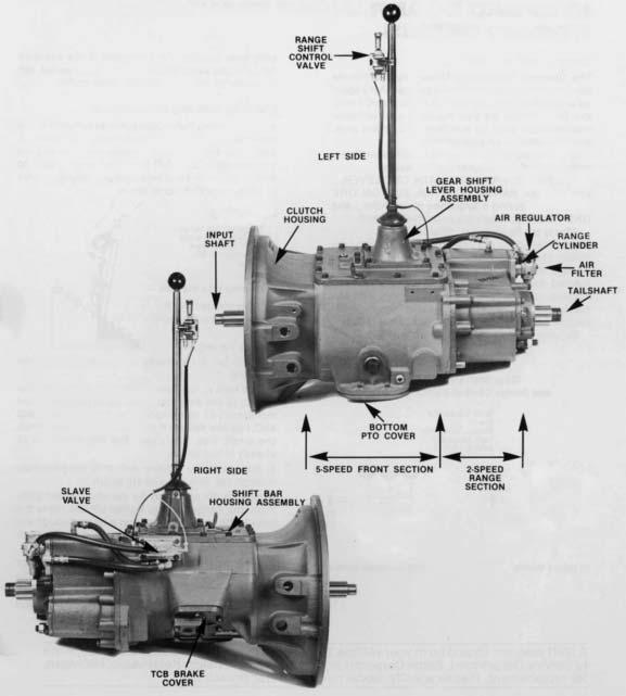
14 AIR SYSTEM Basic Installation and Trouble Shooting Guide NOTE: If the transmission is equipped with a A-5010 Roadranger valve, see the Air Systems Troubleshooting Guide, TRSM-0920, for operation and assembly instructions. Operation The range shift air system consists of an air filter, regulator, air valve, control valve, range air cylinder which is built into the auxiliary housing, fittings, and connecting lines. Range shifts can only be made when the gear shift lever is in, or passing through, neutral. Thus, the range desired can be pre-selected while the shift lever is in a gear position. As the lever is moved through neutral, an actuating plunger in the shift bar housing releases the inter-lock piston allowing it to move to the range position selected. Constant regulated air is supplied to the "S" port of air valve and to the "IN" port of range control valve. With control button down, the control valve is open, and air passes through control valve and to the "P" port of slave valve. This permits air from the constant supply to flow through the low range port in slave valve to the air cylinder in auxiliary housing. Air at the cylinder moves the shift piston and shaft to the rear to engage the low range gear. With the control button up, the control valve is closed, and air is removed from end port of slave valve. This permits movement of the air valve poppet; air from the constant supply to flow through the high range port of the slave valve and to the high range port of range cylinder cover in auxiliary housing. The shift piston and shaft are moved forward to engage the high range or direct gear. When the control button is moved from one position to another, air from the previously charged Iine exhausts through the breather in range control valve.
15 AIR SYSTEM TROUBLE SHOOTING RANGE SHIFT AIR SYSTEM If transmission fails to make a range shift or shifts too slow, the fault may be in the air system or actuating parts in the shifting bar housing. To check the air system and pin-point the trouble area, the following procedures are recommended, using the check points indicated by letters in the diagram on page 11. Checks are to be made with the vehicle engine off, but with normal vehicle air pressure. 1. Incorrect Hook-up With normal vehicle air pressure and gear shift lever in the neutral position, move the control button up and down, from one range to another. a. If lines are crossed between the control valve and the air valve on transmission, there will be a steady flow of air from the bottom exhaust in control valve with button in the up position. b. If lines are crossed between the air valve on transmission and the range cylinder, the transmission gearing will not correspond with the button position. Low range, down position of button, will result in high range gear engagement in the transmission and vice versa. 2. Air Leaks With normal vehicle air pressure and gear shift lever in the neutral position, coat all air lines and fittings with soapy water and check for leaks, moving control button to both positions. a. If there is a steady leak out exhaust of range control valve, there are defective parts or O-rings in the range control valve. b. If there is a steady leak out breather on slave valve: there is a defective O-ring in the slave valve, or there is a leak past O-rings on the range shift cylinder piston. c. If transmission fails to shift into low range or is slow to make the shift and the transmission case is pressurized, see Check Point E. d. Tighten all loose connections and replace defective parts or O-rings. 3. Check Point A, Air Regulator With normal line pressure and gear shift lever in neutral, check exhaust port of air regulator. There should be no leak from this port. Cut off the vehicle air pressure and install air gauge in line at output port of air regulator. Bring vehicle air pressure to normal. Regulated pressure should be 57.5 to Only as a last resort should an adjustment be made with the screw in bottom of regulator. This adjustment has been set for correct operating limits. Any deviation from these limits, especially on regulators which have been in operation for some time, will in most cases be caused by dirt or worn parts. Adjustment of screw will give only a temporary remedy. (1) Turning screw in (clockwise) raises air pressure. (2) Turning screw out lowers air pressure. Air regulator is not serviceable and should be replaced if defective. 4. Check Point B With normal vehicle air pressure and the gear shift lever in the neutral position, pull the control button up to high range and disconnect the 1/8Ó nylon air line from out port of control valve at the air valve. a. When control button is pushed down a steady blast of air will flow from disconnected line. Air will shut off when button is pulled up. This indicates that control valve is operating correctly. Reconnect air line. b. If control valve does not operate correctly, check for restrictions and leaks; leaks indicate bad O-rings. 5. Check Point C With normal vehicle air pressure and gear shift lever in the neutral position, push the control button down to the low range position and disconnect the high range air line, either at fitting on shift cylinder or at side port or slave valve. a. Pull the control button up. There should be a steady flow of air from the high range port. Push button down to shut off air. b. Make sure vehicle engine is off and move the gear shift Iever to a gear position. Pull the button up; there should be no air at high range port. Move the gear shift lever to neutral; there should now be a steady flow of air from the high range port. Push button down to shut off air and reconnect the high range air line. c. If air system operates incorrectly, this indicates that the slave valve is defective, or that actuating parts in shifting bar housing are jammed or defective.
16 AIR SYSTEM 6. Check Point D With normal vehicle air pressure and gear shift lever in the neutral position, pull the control button up to high range and disconnect the low range air line, either at fitting on range cylinder or at bottom port of air valve. a. Repeat procedures under Check Point C, reversing the position of the control button in order to check the low range operation. 7. Check Point E If any of the seals in the range shift cylinder are defective the range shift will be affected. The degree of lost air will govern the degree of failure, from slow shift to complete failure. a. Leak at seal A or B as shown in diagram results in failure to shift into either low or high range; steady leak out air valve breather in both ranges. b. Leak at seal C results in failure to shift into low range; pressurizing of transmission. Check Point E Cross section of range shift cylinder, showing location of seals. Air Valve Pre-Selection the lever is moved to or through neutral. See detailed installation of air valve for installa- tion precaution concerning the actuating pin. An actuating pin protruding from the shifting bar housing prevents the poppet slave valve from moving while the gear shift lever is in a gear position and releases the poppet when
17 AIR SYSTEM IV. RANGE SHIFT AIR LINESãALL MODELS Cut 7001 D-7/84 A. Removal 1. Disconnect the black and white l/8" OD air lines (A and B) from between the slave air valve and the range shift control valve. 2. Disconnect the two 1/4" ID air lines from between the slave air valve and the range shift cylinder. B. Installation 1. Connect the black and white 1/8" OD supply air line between the forward port on the slave air valve and the rear port on the range shift control valve. 2. Install the black l/8" OD signal air line between the rear port on the slave air valve and the forward port on the range control valve. 3. Use the chart to install the 1/4" ID air lines between the slave air valve side cap and the range shift cylinder.
18 AIR SYSTEM VI. RANGE CONTROL VALVE A. Removal and Disassembly 1. Disconnect the air lines and loosen the clamp securing the valve to the gear shift lever. Remove valve. 2. Remove the four screws to separate the front and rear housings and remove the slide and two sets of position springs and balls. 3. Remove the valve plate, insert O-rings and wave washer from the valve bodies. 4. If necessary, remove the two felt seals. Punch out the roll pin to remove the button from the slide. B. Reassembly and Installation 1. Refer to the drawing for proper reassembly. Use a VERY SMALL amount of silicone lubricant on the O-rings to avoid clogging the ports. A small amount of grease on the position springs and balls will help to hold them in place during reassembly. 2. Install the air lines with their sheathing and O-rings on the gear shift lever. 3. Secure the valve on the gear shift lever with the clamp. The control button should face to the front and be approximately 6" below the centerline of the shift knob or selector valve. 4. Attach the air lines.
19 AIR SYSTEM AIR FILTER AND REGULATOR The air filter contains a replaceable filter element which can be removed by turning out the end cap and removing the spring and tension plate. This element should be cleaned at each oil change, or more often under high humidity conditions.
20 PRECAUTIONS DISASSEMBLY It is assumed in the detailed disassembly instructions that the lubricant has been drained from the transmission, the necessary linkage and air lines removed and the transmission has been removed from the chassis. Removal of the gear shift lever housing assembly is included in the detailed instructions; however, this assembly must also be removed from transmission before removing unit from vehicle. Follow each procedure closely in each section, making use of both the text and pictures. 1. BEARINGS - Carefully wash and relubricate all bearings as removed and protectively wrap until ready for use. Remove bearings with pullers designed for this purpose. 2. ASSEMBLIES - When disassembling the various assemblies, such as the mains shaft, countershafts and shifting bar housing, lay all parts on a clean bench in the same sequence as removed. This procedure will simplify re-assembly and reduce the possibility of losing parts. 3. SNAP RINGS - Remove snap rings with pliers designed for this purpose. Rings removed in this manner can be reused. 4. INPUT SHAFT - The input shaft can be removed without removing the countershafts, mainshaft or drive gear. 5. CLEANLINESS - Provide a clean place to work. It is important that no dirt or foreign material enters the unit during repairs. The outside of the unit should be carefully cleaned before starting the disassembly. Dirt is abrasive and can damage bearings. 6. WHEN DRIVING - Apply force to shafts, housings, etc., with restraint. Movement of some parts is restricted. Do not apply force after the part being driven stops solidly. Use soft hammers and bars for all disassembly work. INSPECTION Before reassembling the transmission, the individual parts should be carefully checked to eliminate those damaged from previous service. This inspection procedure should be carefully followed to insure the maximum of wear life from the rebuilt unit. The cost of a new part is generally a small fraction of the total cost of downtime and labor, should the use of a questionable part make additional repairs necessary before the next regularly scheduled overhaul. Recommended inspection procedures are set forth in the following check list:
21 PRECAUTIONS A. Bearings 1. Wash all bearings in clean solvent. Check balls, rollers and races for pits and spalled areas. Replace bearings which are pitted or spalled. 2. Lubricate bearings which are not spalled or pitted and check for axial and radial clearances. Replace bearings with excessive clearances. 3. Check fit of bearings in case bores. Bearings should be tight to shaft, slightly tight to slightly loose to bearing bore. B. Gears 1. Check operating gear teeth for pitting on the tooth faces. Gears with pitted teeth should be replaced. 2. Check all engaging gear teeth. Gears with teeth worn, tapered or reduced in length from clashing in shifting should be replaced. 3. Check axial clearances of gears. Where excessive clearance is found, check gear snap ring, washer, spacer and gear hub for excessive wear. Maintain.005 to.012 axial clearance of mainshaft forward speed gears,.005 minimum on reverse gear. C. Splines 1. Check splines on all shafts for wear. If sliding clutch gears, companion flange or clutch hub have worn into the sides of the splines, the shafts in this condition should be replaced. D. Thrust Washers 1. Check surfaces of all thrust washers. Washers scored or reduced in thickness should be replaced. E. Reverse Gear and Shaft 1. Check bearing sleeve for wear from action of roller bearings. G. Clutch Release Parts 1. Check clutch release parts. Replace yokes worn at cam surfaces and bearing carrier worn at contact pads. 2. Check pedal shafts. Replace those worn at bearing surfaces. H. Shifting Bar Housing Assembly 1. Check yokes and blocks for wear at pads and lever slot. Replace worn parts. 2. Check yokes for alignment. Replace those which are sprung. 3. Check yokes for excessive wear; replace worn yokes. 4. Check Iockscrews in yokes and blocks. Retorque and rewire those found loose. 5. If housing has been dismantled, check neutral notches of shifting bars for wear from interlock balls. Bars indented at points adjacent to the neutral notch should be replaced. I. Gear Shift Lever Housing Assembly 1. Check spring tension on shift lever. Replace tension spring and washer if lever moves too freely. 2. If housing is dismantled, check pivot or spade pin and corresponding slot in lever for wear. Replace both parts if worn. J. Oil Return Threads and Seals 1. Check oil return threads in front bearing cover. If sealing action of threads has been destroyed by contact with input shaft, replace the cover. 2. Check oil seal in mainshaft rear bearing cover. If sealing action of lip has been destroyed, replace seal. F. Gray Iron Parts 1. Check all gray iron parts for cracks and breaks. Replace or repair parts found to be damaged. Heavy castings may be welded or brazed providing the cracks do not extend into bearing bores or bolting surfaces.
22 PRECAUTIONS K. Synchronizers 1. Check high and low range synchronizers for burrs, uneven and excessive wear at contact surface, and metal particles. 2. Check blocker pins for excessive wear or looseness. 3. Check synchronizer contact surfaces on the high and low range gears for excessive wear. L. Sliding Clutches 1. Check all yokes and yoke slots in sliding clutches for wear or discoloration from heat. 2. Check engaging teeth of sliding clutches for partial engagement pattern. 3. O-RINGS - Lubricate all O-Rings with silicone lubricant. 4. ASSEMBLY - Refer to the disassembly illustrations as a guide to reassembly. 5. INITIAL LUBRICATON - Coat all thrust washers and splines of shafts with Lubriplate during installation to provide initial lubrication, preventing scoring and galling. 6. AXIAL CLEARANCES - Maintain original axial clearances of mainshaft forward speed gears of.005" to.012". Mainshaft reverse gear clearance is a minimum of.005". M. O-Rings 1. Check all O-rings for cuts, cracks or distortion. Replace if worn. REASSEMBLY Make sure that interiors of case and housings are clean. It is important that dirt be kept out of transmission during reassembly. Dirt is abrasive and can damage polished surfaces of bearings and washers. Use certain precautions, as listed below, during reassembly. 1. GASKETS - Use new gaskets throughout the transmission as it is being rebuilt. Make sure all gaskets are installed, as omission of gasket can result in oil leakage or misalignment of bearing covers. See "Location of Gaskets" heading. 7. BEARING - Use of flanged-end bearing drivers is recommended for the installation of bearings. These drivers apply equal force to both races of bearing, preventing damage to balls and races and maintaining correct bearing alignment with shaft and bore. If tubular or sleeve type driver is used, apply force only to inner race. 8. UNIVERSAL JOINT COMPANION FLANGE - Pull the companion flange tightly into place with the mainshaft nut, using foot-pounds of torque. Make sure the speedometer gear has been installed on yoke. If a speedometer gear is not used, a replacement spacer of the same width must be used. Failure to pull the yoke or flange tightly into place will permit the shaft to move axially with resultant damage to rear bearing. 2. CAPSCREWS - To prevent oil leakage, use thread sealant on all capscrews. See torque rating chart for recommended torque. 9. TORQUE - As you reassemble transmission, refer to pages 12 and 13 for proper installation torque of capscrews, nuts and plugs.


23 DISASSEMBLY I. RANGE SHIFT AIR SYSTEM A. To Remove the Range Shift Control Valve. 1. Disconnect the two nylon air lines at air valve on transmission. NOTE: If desired, the gear shift lever housing lever and range control valve can now be removed from the transmission as a unit by turning out the four capscrews which attach the housing to the transmission. 2. Disconnect the two nylon air lines at the control valve on gear shift lever, and remove the ball grip from gear shift lever.


24 DISASSEMBLY C. To Remove the Slave Valve. 3. Loosen the mounting clamp and remove the range control valve and mounting clamp from lever. 4. Remove nylon air lines, sheathing and O-ring clamp from the gear shift lever. B. To Remove Air Regulator and Filter Assembly Remove the two air lines between the slave valve and range cylinder in auxiliary. Turn out the four capscrews and remove the slave valve from transmission. Remove sleeve from slave valve. 1. Disconnect and remove the air line between the slave valve and air regulator. 3. If necessary, remove fittings from slave valve Remove street ell and reducer from regulator if necessary. Turn the nipple from air regulator. Turn out capscrews and remove the air regulator and filter assembly from transmission. 4. Remove the actuating spring and pin from bore in transmission.
25 I SHIFTING CONTROLS IX. GEAR SHIFT LEVER HOUSING


26 SHIFT CONTROLS A. Removal and Disassembly B. Reassembly and Installation 1. Turn out the capscrews, jar lightly to break the 1. Install the spade pin or pivot pin, nut and gasket seal and remove the gear shift lever hous- washer in the bore in the housing. If previously ing from the shift bar housing. removed, install the O-ring in the groove. 2. Secure the housing in a vise and use a large screwdriver to twist between the spring and side of the housing, forcing the spring from under the three lugs. Do one coil at a time. Remove the spring. 3. Remove the washer and gear shift lever. 4. Remove the spade pin or pivot pin, nut and washer from the bore in the housing. If necessary, remove the O-ring from the housing. 2. Install the gear shift lever in the housing, fitting the slot in the lever ball over the spade pin. 3. Place the tension spring washer over the lever ball with the dished side up. 4. Seat the tension spring under the lugs in the housing, seating one coil at a time. Use of a spring driving tool is recommended. 5. Make sure that the three tension springs and balls are in the shift bar housing bores and install the gear shift lever housing and gasket on the shift bar housing.


27 DISASSEMBLY Ill. SHIFTING BAR HOUSING A. To Remove and Disassemble the Shifting Bar Housing. 1. Turn out the attaching capscrews, jar to break 2. Turn out the two capscrews and remove the gasket seal, and lift the shifting bar housing tension spring cover from top of housing. from transmission. 3. Remove the three tension springs installed under cover.


28 DISASSEMBLY 4. Tilt housing and remove the three tension balls installed under springs. 7. Move top shifting bar to the right and out of housing, removing shifting yoke-from bar Place the housing in a vise with the plunger side up; front of housing will be to the right. Starting with the upper bar, move all bars to the right and out front of housing as detailed in the following instructions. Cut lockwire and remove Iockscrews from each bar just prior to its removal. 8. Move center bar to the right and out of housing, removing shifting yoke from bar. As neutral notch in bar clears the front web, remove the interlock pin from bore in neutral notch. NOTE: During disassembly, lay all parts on a clean bench in the order of removal to facilitate reassembly. Bars not being removed must be kept in the neutral position or interlock parts will lock bars.


29 DISASSEMBLY 9. Remove the actuating plunger from rear web. 11. Remove the two interlock balls from front web. 10. Move the lower bar to the right and out of housing, removing shifting yoke from bar.


30 DISASSEMBLY IV. COMPANION FLANGE, AUXILIARY SECTION AND CLUTCH HOUSING REMOVAL A. To Remove the Universal Joint Companion Flange or Yoke. 1. Lock the transmission by engaging two speeds with the mainshaft sliding clutches. Use a large breaker bar to turn the output shaft nut from the output shaft. 2. Pull the flange or yoke straight to the rear and off shaft.


31 DISASSEMBLY B. To Remove the Auxiliary Section from Transmission. C. 1. To Remove the Clutch Housing and Front Bearing Cover. Remove the clutch release mechanism if so equipped. 1. Turn out the capscrews that attach the two sections. 2. Remove nuts from the six studs and turn out the two bolts which attach clutch housing to case. 2. Insert puller screws in auxiliary housing flange. 3. Break gasket seal and remove clutch housing from case. 3. Tighten puller screws evenly to move the auxiliary section straight to the rear and from front section. 4. Turn out capscrews and remove the front bearing cover. (Tap against drive gear from inside case to move cover forward to break gasket seal.)


32 DISASSEMBLY V. FRONT SECTION DISASSEMBLY A. To Remove Bearings from Right Countershaft. 1. Remove snap ring in rear bearing bore of case. 3. Install snap ring in the exposed bearing snap ring groove. (Use snap ring which was removed from rear bearing bore.) 4. Loosen the capscrews at the bearing retaining 2. Using soft bar and maul against rear of counter- rings on auxiliary drive gear. This will allow shaft, move the assembly forward as far as movement to the rear of the countershaft and possible until snap ring groove in front bearing mainshaft assemblies. is exposed. NOTE: If front bearing snap ring groove can not be exposed (due to variances in thickness of case), use punch between hub of countershaft drive gear and inner race of bearing to move the gear forward on shaft.


33 FRONT SECTION DISASSEMBLY 5. Using soft bar and maul against front of 7. Use puller or pry bars to remove front bearing. countershaft, move the countershaft assembly to the rear as far as possible. This will move front bearing forward on shaft. 6. Using soft bar and maul against rear of countershaft, again move the countershaft as far forward as possible to unseat front bearing from case bore. 8. Use a maul and punch from inside the case to drive the rear bearing to the rear and from the case bores. NOTE: Removal procedures will damage the bearings and removal should not be attempted unless replacement of the bearings is planned.


34 FRONT SECTION DISASSEMBLY B. To Remove the Input Shaft. 1. Move the drive gear and shaft forward as far as possible. 3. Push down on input shaft to cock bearing in bore. Drive input shaft toward rear of transmission, through bearing as far as possible. Pull input shaft forward to expose snap ring of bearing. 2. Remove the bearing retaining snap ring from groove in shaft. 4. Use pry bars to complete removal of bearing.


35 .-Ó FRONT SECTION DISASSEMBLY 5. Remove the drive gear washer. 8. If necessary, remove bushing from pocket in clutch shaft. 6. Remove the snap ring from groove in ID of drive gear. 9. Move the drive gear to the rear and against the 4th speed gear, engaging teeth of sliding clutch gear. 7. Pull shaft forward and from splines of drive gear.


. 1.")


36 FRONT SECTION DISASSEMBLY Cut /80 C. To Remove and Disassemble the Auxiliary Drive Gear Assembly. 2. Remove the snap ring from the rear of mainshaft (located in bore of auxiliary drive gear). 1. Turn out capscrews and remove the two bearing retainer rings from case. 3. Tap against front of mainshaft to move the auxiliary drive gear bearing to the rear, exposing the bearing snap ring.


37 FRONT SECTION DISASSEMBLY 4. Use pry bars to remove the auxiliary drive gear assembly from case bore and from splines of mainshaft. 6. Press or use driver to remove bearing from auxiliary drive gear. 5. Remove snap ring from groove in auxiliary drive gear.


38 FRONT SECTION DISASSEMBLY D. To Remove the Left Reverse Idler Gear. 1. Use curved pry bar to walk bearing from idler bore in case. 2. Remove the rear idler washer and retainer from bore. (If necessary, bend holder lugs and remove washer from holder.)


39 FRONT SECTION DISASSEMBLY 3. Remove reverse idler gear from case. 5. Remove the front idler washer from case 4. Remove the idler bearing from reverse idler gear.


40 FRONT SECTION DISASSEMBLY E. To Remove and Disassemble the Mainshaft Assembly. 1. Block the right countershaft to the right as far as possible-and lift the mainshaft assembly from case. 3. Inside hub of the 4th speed gear, remove snap ring from groove in mainshaft.. 2. Remove the drive gear and the 4th-5th sliding clutch from mainshaft. 4. Remove the 4th speed gear and washer.


41 FRONT SECTION DISASSEMBLY 5. Remove the 3rd speed gear and washer. 7. Remove the long key from slot in mainshaft. 6. Remove the 2nd-3rd speed sliding clutch. 8. Remove the 2nd speed gear and washer.


42 FRONT SECTION DISASSEMBLY 9. Remove the 1st speed gear and washer. 11. Remove the reverse gear and washer. 10. Remove the 1st-reverse sliding clutch.


43 FRONT SECTION DISASSEMBLY F. To Remove the Countershaft Assemblies. 3. Lift the left countershaft from case Lift the right countershaft from case. Remove bearings from the left countershaft in the same manner in which bearings were removed from right countershaft. (See pages 33 and 34.)


44 FRONT SECTION DISASSEMBLY G. To Disassemble the Countershaft Assemblies. NOTE: Both countershafts are disassembled in the same manner as construction is identical. 3. Press the 4th speed gear from shaft. 1. Remove snap ring from front of countershaft. 2. Press the drive gear from shaft. 4. Using the rear face of the PTO gear as a base in press, press the 3rd speed gear, and the PTO-2nd speed gear cluster from shaft. 5. If necessary, remove woodruff key, long key and roll pin from shaft. H. To Remove the Right Reverse Idler Gear. The right reverse idler gear assembly is identical to the left and is disassembled in the same manner.


45 FRONT SECTION DISASSEMBLY VI. AUXILIARY DISASSEMBLY Cut 6482 Ð2/80 A. To Remove the Auxiliary Countershaft Assemblies. 2. Turn out capscrews and remove the rear bearing cover. 1. Use pullers to remove bearing from front of tailshaft. 3. If necessary remove the rear seal from cover.


46 AUXILIARY DISASSEMBLY 4. Remove the speedometer gear or replacement spacer from tailshaft. 5. Remove the speedometer gear washer. 7. Pull the counters shafts forward and out of housing. 6. From inside housing, use long punch to move outer races of countershaft rear bearings to the rear; move races approximately one-half inch. 8. If necessary pull bearing inner races from front and rear of countershaft. (Rear race removal is shown.)


47 AUXILIARY DISASSEMBLY I C. To Remove the Range Shift Air Cylinder and - Synchronizer Assemblies. 1. Turn out capscrews and remove the air cylinder cover. 3. Use air to remove piston. CAUTION - DO not stand in front of cylinder opening. 4. If necessary remove O-ring from OD of piston. 2. Remove the nut and Iockwasher from air cylinder piston shaft.


48 AUXILIARY DISASSEMBLY 5. Remove the copper seal from shaft.. 9. Place the larger low range synchronizer ring on bench. 10. Pull upward to remove the high range synchronizer from pins. CAUTION. There are three springs located in housing of high range synchronizer which will be released as high range synchronizer is removed from pins. It may be helpful to cover assembly with rag to prevent losing springs. 6. Move the synchronizer assembly, shift yoke, and piston shaft forward and out of housing as a complete assembly. 11. Remove the sliding clutch from low range synchronizer pins. - D. To Remove and Disassemble the Air Cylinder Assembly Remove the shaft and yoke from synchronizer assembly. Cut lockwire, turn out the two Iock screws and remove yoke from shaft. 1. Important: Remove the dust seal, and air port extension from top of housing.


49 AUXILIARY DISASSEMBLY E. To Remove and Disassemble the Low Speed Gear and Tailshaft Assembly. 2. Remove cylinder from housing. 1. Drive or press against rear of tailshaft to move assembly forward and from rear bearing. 3. Remove O-ring from small bore in cylinder, if necessary. 2. Remove the rear washer and the low speed gear from rear of shaft.


50 AUXILIARY DISASSEMBLY 3. Remove spline washer from hub of low speed gear Move the mainshaft rear bearing to the rear and out of housing. Use bearing driver to remove the countershaft rear bearings from housing.


51 AUXILIARY REASSEMBLY I. AUXILIARY REASSEMBLY Cut /85 A. To Reassemble and Install the Low Speed Gear and Tailshaft Assembly. 1. Make sure magnetic cleaner is installed in recess in auxiliary case. 3. Place splined spacer in hub of low speed gear, shoulder toward rear. 2. IMPORTANT: Mark timing teeth on the reduction gear. a. Mark any two adjacent gear teeth on low speed gear. b. Then, mark the two adjacent teeth which are directly opposite the first set marked. There should be the same number of teeth between the markings on each side of the gear. 4. Install the low speed gear and spacer over rear of shaft and against shoulder. Clutching teeth down.


52 AUXILIARY REASSEMBLY 5. Install the low speed gear rear washer on shaft and against gear, chamfer to the rear. 7. Seat mainshaft rear bearing securely on shaft and in bore. 6. Set the tailshaft with the forward end down and place auxiliary housing over rear of shaft so that shaft extends through rear bore.


53 AUXILIARY REASSEMBLY B. To Install the Range Shift Air Cylinder. 1. Install O-ring in slot in small bore in cylinder. Lubricate O-ring with silicone lubricant. 2. Install range cylinder in housing with air port in cylinder aligned with air port in top of auxiliary housing.


54 AUXILIARY REASSEMBLY 3. Install dust cover and airport extension through housing and into bore of air cylinder. C. To Reassemble the Synchronizer Assembly. 3. Install the three springs in bores in high range synchronizer ring. 1. Place the larger low range synchronizer ring face down on bench with pins up. 2. Place the sliding clutch, recessed side up, on pins of low range synchronizer. 4. Place the high range synchronizer ring over pins of the low speed synchronizer ring, seating springs against pins.


55 AUXILIARY REASSEMBLY 5. Seat the direct ring fully on the low speed pins by pushing down and twisting to compress the springs. D. To Install the Synchronizer and Range Shift Air Cylinder Assemblies Place yoke in slot of sliding clutch; threaded end of piston shaft is towards the larger low range synchronizer. Place the entire assembly into auxiliary housing, exgaging splines or sliding clutch with tai lshaft and inserting piston shaft through cylinder bore Place the shifting yoke on piston shaft, long hub towards the rear of the shaft. Align slots in shaft with bores in Yoke hub and install the two Iockscrews secure with safety wire. 5. Install copper seal on threaded end of piston shaft.


56 AUXILIARY REASSEMBLY 6. Install O-ring on OD of piston. Apply light coat of silicone lubricant to O-ring E. Install gasket and cylinder cover, tighten the four capscrews securely. To Reassemble the Countershaft Assemblies. 7. Install piston on shaft and against copper washer, flat side of piston out. 1. Install bearing inner race on front and rear of countershaft. 8. Install Iockwasher and nut on shaf to secure piston. 2. IMPORTANT: To mark countershaft gear teeth for timing. Mark the tooth on the countershaft low speed gear which is stamped with an "O".


57 AUXILIARY REASSEMBLY F. To Install the Countershaft Assemblies. 1. Seat the outer races of the countershaft rear bearings only partially in bores, just far enough to stay in place. 3. With countershafts in position, complete the installation of the countershaft rear bearings on shaft and into case bore. Seat securely. 2. Place countershafts into position in auxiliary housing, inserting inner races into the partially installed outer races. IMPORTANT: Timing countershaft gears with low speed gears. As the countershafts are installed, mesh the marked low speed gear tooth on each countershaft between each set of marked gear teeth on the low speed gear.


58 AUXILIARY REASSEMBLY 4. Install the speedometer gear rear washer on tailshaft and against bearing, champh ered ID towards bearing, and install the speedometer gear or replace merit spacer on shaft and against washer. 7. Install bearing on front of tailshaft. 5. If previously removed, install oil seal in rear bearing cover, lip of seal to the rear. The spring in the seal should be toward the inside of the transmission. 6. Install the rear bearing cover with the speedometer bore up and to the left, tighten cap screws securely.


59 FRONT SECTION REASSEMBLY Il. FRONT SECTION REASSEMBLY A. To Install the Right Reverse Idler Gear Assembly. 3. Install needle bearing through rear bore and into hub of reverse gear. 1. Apply a heavy coat of white grease on the reverse-idler gear front washer and install it on pin in lower right of case. 4. Place rear washer in holder if previously removed, and bend lugs to secure washer. 5. Place washer and holder into reverse gear case bore, holder flange to the rear. 2. Set reverse gear in position next to washer, machined surface of gear hub to the rear. 6. Install the auxiliary countershaft front bearing into the reverse gear case bore to hold the reverse idler gear assembly in position. NOTE: The front portion of the auxiliary countershaft is used as a journal for the reverse idler gear.


60 FRONT SECTION REASSEMBLY B. To Assemble the Countershaft Assemblies. NOTE: Countershafts are identical and are assembled in the same manner. 3. Press the 3rd speed gear on shaft. 1. If previously removed, install roll pin, long key and woodruff key in slots in countershaft. 4. Press the 4th speed gear on shaft, long hub to the front. 2. Press the PTO-2nd speed gear cluster on countershaft, PTO gear to the front.


61 FRONT SECTION REASSEMBLY C. To Mark Timing Teeth and Position Countershaft Assemblies. 1. On the drive gear of each countershaft mark the gear tooth which is aligned with the keyway in shaft. This tooth will be stamped with an "O". 5. Press drive gear on shaft, long hub to the rear. 2. Place the left countershaft into position in case - install bearings as shown in illustrations 4, 5, 6 and Install snap ring in groove at front of shaft. 3. Place the right countershaft into position in case--do not install bearings.


62 FRONT SECTION REASSEMBLY 4. Center rear of left countershaft in rear bore of case with block. 7. Install snap ring in groove in rear bore of case. D. To Assemble Auxiliary Drive Gear Assembly. 5. Install front bearing on countershaft and in case bore with flanged driver. 1. Press bearing on auxiliary drive gear, snap ring in groove towards gear. 6. Install rear bearing on countershaft and in case bore with flanged driver. 2. Install bearing retaining snap ring in groove of auxiliary drive gear shoulder.


63 FRONT SECTION REASSEMBLY E. To Reassemble the Mainshaft Assembly. 3. Install long key, from the bottom, in keyway in mainshaft to lock reverse gear splined washer to mainshaft. 1. Place the mainshaft in a vise with the pilot end down. Keep keyway in mainshaft clear for insertion of key. NOTE: Each mainshaft gear is held in position by locking the gear splined washer to the mainshaft with key. There is one splined washer for each gear. Splined washers for the reverse, 1st, 2nd, and 3rd speed gears are the same diameter, the 4th speed gear splined washer is of smaller diameter. 4. Install reverse gear on splined washer with clutching teeth facing down. 2. Install reverse gear splined washer in groove near rear of mainshaft. NOTE: Make sure long key is positioned with the word "top" on key to the outside. During reassembly the long key will be removed and re-installed to assure that washers stay in position. 5. Install auxiliary drive gear on mainshaft with clutching teeth facing up.
64 FRONT SECTION REASSEMBLY SETTING CORRECT AXIAL CLEARANCES FOR MAINSHAFT GEARS Axial Clearance (End Play) Limits Are: Reverse speed gear - Minimum of.005" Forward speed gears -.005" to.012" Washers are used to obtain the correct limits; Five thicknesses are available as follows: LIMITS COLOR CODE Orange Purple Yellow Black Red Refer to Illustrated Parts Lists for washer part numbers. Always use the low limit washer in the 1st GEAR and 3rd SPEED GEAR positions as shown at right. Refer to the service manual covering mainshaft reassembly for method of assembling parts. Reverse gear clearance must be set as low as possible to the minimum.005". Clearance can be measured before the mainshaft assembly is installed in the case. This is done by securing the reverse gear in position on mainshaft with the reverse gear snap ring and the front snap ring; then, secure auxiliary drive gear assembly in position at rear of mainshaft with the rear snap ring. **On overdrive models, the (4th) speed gear becomes (5th) speed gear.


65 FRONT SECTION REASSEMBLY 6. Install snap ring in groove at rear of m/shaft. 9. Install the 1st-reverse clutch over front of mainshaft and against reverse gear splined washer. Align slot in sliding clutch with key. 7. Insert two large screw drivers between hub of reverse gear and auxiliary drive gear applying light downward pressure on handles of screwdrivers. 10. Remove long key from keyway in mainshaft. Install 1st speed gear splined washer on mainshaft at 1st speed gear location and re-install the long key to lock splined washer to shaft. 8. Check clearance between the two gears with feeler gauge. Clearance can be adjusted by replacing reverse gear splined washer with different thickness washer. Proper clearance at this location should be a minimum of.005". After proper reverse gear clearance has been set, remove snap ring from rear of mainshaft in vise, place front (pilot end) of mainshaft in vise.


66 FRONT SECTION REASSEMBLY 11. Install 1st speed gear on mainshaft, clutching teeth down, fitting gear splines on those of washer Remove the long key from keyway in mainshaft. Install 2nd speed gear splined washer on mainshaft and into hub of 2nd speed gear. 12. Install 2nd speed gear on mainshaft, clutching teeth up, and against 1st speed gear. 15. Install long key in keyway in mainshaft to lock washer to shaft.


67 FRONT SECTION REASSEMBLY 16. Insert 2 large screwdrivers between the Install 3rd gear splined washer on mainshaft at gears. Apply slight downward pressure then 3rd speed gear location. It will be necessary to insert feeler gauge between the hubs of the pull long key upward slightly in order to fit gears to check axial clearance. Correct clear- splined washer over key cross pin and to fit key ante should be.005" to.012". in keyway. Re-position key so that cross pin rests on top of washer. 17. Install the 2nd-3rd speed sliding clutch, aligning slot in sliding clutch with key; engage with 2nd speed gear. 19. Install the 3rd speed gear on mainshaft, fitting gear splines on those of washer.


68 FRONT SECTION REASSEMBLY 20. Install the 4th speed gear on mainshaft 22. (clutching teeth up) and - against 3rd speed gear. Install snap ring in groove in mainshaft which will hold the 4th speed gear in position on shaft. 21. Install the 4th speed gear splined washer on mainshaft and in hub of 4th speed gear. 23. Install the 4th-5th speed sliding clutch on mainshaft, engage clutch with 4th speed gear. The side marked "front" should be facing up.
. a. Mark two adjacent teeth on drive gear. b.")


69 FRONT SECTION REASSEMBLY 24. IMPORTANT: Mark timing teeth on drive gear 26. (5th speed gear). a. Mark two adjacent teeth on drive gear. b. Mark the two adjacent teeth on drive gear which are directly opposite the first set marked. There should be the same number of teeth between markings on each side of F. gear. Remove the assembly from vise and install the reverse gear on rear of mainshaft, engaging splines of gear with those of splined washer on mainshaft. To Install Mainshaft Assembly. 25. Install the drive gear on mainshaft and against the 4th speed gear, snap ring groove in drive 2. gear to the front. 1. Move right countershaft toward case wall as far as possible. Place mainshaft assembly in position in case.


70 FRONT SECTION REASSEMBLY 3. If previously removed, install bushing in pocket of input shaft, flush with rear of shaft. 5. Center mainshaft in rear bore of case and install auxiliary drive gear on splines of mainshaft. 4. Install input shaft through bore of case and onto mainshaft. This will prevent the mainshaft assembly from dropping to bottom of case. 6. Seat auxiliary drive gear bearing in rear bore of case.


71 FRONT SECTION REASSEMBLY 7. Install the two bearing retainer plates and locking tabs on case. 9. With large screwdriver move mainshaft assembly to rear to expose snap ring groove on rear of mainshaft. Install snap ring on rear of mainshaft. 8. Tighten capscrews and secure by bending locking tangs over capscrews. 10. Install the input shaft in the splines of drive gear by moving drive gear forward against inside wall of case.


72 FRONT SECTION REASSEMBLY 11. Mesh the marked timing tooth of left countershaft drive gear with the two marked timing teeth of the main drive gear. 13. Install drive gear spacer on input shaft. 12. Install snap ring in groove in I.D. of drive gear. 14. Install drive gear bearing on input shaft and into case bore.


73 FRONT SECTION REASSEMBLY 15. Install bearing retaining snap ring in groove of input shaft. 17. Mesh the marked timing tooth of the right countershaft drive gear with the two marked timing teeth of the main drive gear making sure the left countershaft remains in time. 16. Engage the 4th-5th sliding clutch into the 4th speed mainshaft gear. This will prevent the 4th speed from dropping far enough to cause a possible timing error in the 4th speed gear set. 18. Hold countershaft in position and partially install front and rear bearings in case bores and on countershaft.


74 FRONT SECTION REASSEMBLY 19. Shift the mainshaft sliding clutches into all the gear positions with a screwdriver. If a clutch cannot be shifted into a gear it indicates that the gear set is out of time. The right countershaft bearings would then need to be removed and the countershaft retimed with the mainshaft. The front box is properly timed if the sliding clutches can be shifted into all the mainshaft gears. (Note: Do not shift the transmission into two gears at the same time. This will prevent the transmission from rotating.) 20. Use a flanged bearing driver to complete seating of both front and rear bearings. 21. Install snap ring in groove in rear bore of case.


75 FRONT SECTION REASSEMBLY G. To Install the Left Reverse Idler Gear Assembly. 3. Set reverse-idler gear in position, machined surface of gear hub to the rear. 4. Place rear washer in holder if previously removed, and bend lugs to secure washer. 1. Apply heavy coat of white grease on washer and on pin in upper left of case. 5. Place washer and holder into reverse gear case bore, holder flange to the rear. 2. Install needle bearing in hub of reverse-idler gear. 6. Install the auxiliary countershaft front bearing into the reverse-gear case bore to hold the reverse idler gear assembly in position. NOTE: The front portion of the auxiliary countershaft is used as a journal for the reverse idler gear.


76 FRONT SECTION REASSEMBLY Ill. CLUTCH HOUSING, AUXILIARY SECTION AND COMPANION FLANGE INSTALLATION A. To Install the Clutch Housing. B. To Install the Auxiliary Section. 1. Install the drive gear bearing cover. NOTE: The two reverse gears, including the washers, must be in perfect alignment with center of case bores as the front of the auxiliary countershafts must be inserted in these parts during auxiliary installation. A heavy grease or Iubriplate will help hold washers in place. Also check rear of front section to make sure all snap rings have been installed. 2. Install the clutch housing, attaching securely with the six nuts and two bolts. 3. If so equipped, install the clutch release mechanism 1. Install auxiliary section on front section, aligning auxiliary section on dowel pins and the extended portion of auxiliary countershafts with reverse idler gears. It may make assembly easier if someone slowly rotates input shaft during installation.


77 FRONT SECTION REASSEMBLY 2. Secure the auxiliary with attaching capscrews. C. To Install the Companion Flange or Yoke. NOTE: The auxiliary can also be installed with front section in a vertical position. Place clutch housing on blocks and use chain hoist to lower auxiliary section into position. 1. Lock transmission by engaging two gears with the mainshaft sliding clutches.


78 FRONT SECTION REASSEMBLY 4. Install the companion flange nut., Tighten securely, using the correct torque rating. 2. Make sure the speedometer gear washer and the speedometer gear or replacement spacer are installed on tailshaft. 3. Install the companion flange on splines of tailshaft.


79 FRONT SECTION REASSEMBLY IV. SHIFTING BAR HOUSING A. To Reassemble the Shifting Bar Housing Assembly. 1. Place the housing in a vise with the front of housing to the right. 2. Install the 4th-5th speed shift bar in bottom bore with neutral notches to the front, installing yoke on bar, fork towards front. Install yoke lockscrew and safety wire keep bar in neutral position. 5. Install the 2nd-3rd speed shift bar in center bore, and install yoke on bar, Iockscrew hole to the rear of fork; insert interlock pin in bore in neutral notch. Install yoke Iockscrew and safety wire. 3. Install interlock ball in vertical bore in front web. 6. Install interlock ball in vertical bore in front web. 4. Install plunger in vertical bore in rear web. 7. If previously removed, install the reverse-stop plunger in the reverse yoke. Make sure that the plunger is fully seated in the bore.


80 FRONT SECTION REASSEMBLY 8. Install the spring in the bore and on the plunger. 11. Remove assembly from vise and install the three tensions balls, one in each bore in top of housing. Keep bars in neutral. 9. Partially install the plug. Use the tip of the gear shift lever to push the plunger back into the bore to compress the spring. Tighten the plug fully and then back off 1/2-1 1/2 turns. Stake the plug threads in the hole. 12. InstalI the three tension springs, one in each bore in top of housing. 10. Install first-reverse shift bar in upper bore, neutral notches to the front, installing yoke on bar, fork to the rear. Install yoke Iockscrew and safety wire. 13. Install the tension spring cover. Tighten capscrews securely.


81 FRONT SECTION REASSEMBLY B. To Install the Shifting Bar Housing Assembly. 1. Make sure the shift bars are in the neutral position. 3. Install the shifting bar housing on transmission, fitting yokes into yoke slots of corresponding clutch gears. 2. Place the sliding clutches on the mainshaft in the neutral position. 4. Install the attaching capscrews, tighten securely.


82 FRONT SECTION REASSEMBLY VI. RANGE SHIFT AIR SYSTEM A. To Install the Air Valve NOTE: If previously removed install fittings on slave valve. 3. Install the slave valve on transmission, tighten capscrews evenly and securely. Actuating plunger in case fits into alignment sleeve in air valve. 1. Install the actuating pin and spring in bore in transmission. 4. Install the high range air line between the air port in the rear cover of the range cylinder and the "H" port of the slave valve. 2. Make sure the alignment sleeve is installed in air valve.


83 REASSEMBLY 5. Install the low range air line from air port in top of cylinder to the street ell in the "L" port of the slave valve. 6. Install air line between output port of air regulator and the tee in supply port of air valve. B. To Reassemble and Install the Air Regulator and Filter Assembly. 5. Install the air regulator and filter assembly on mounting surface on the range cylinder, tighten capscrews securely.


84 REASSEMBLY c. To Install the Range Control Valve. 1. Install O-ring clamp on gear shift lever. 2. Install the control valve on gear shift lever with clamp, and replace ball grip on gear shift lever. Position top of control valve button at least six inches below ball grip. 6. Install the black nylon air line from the "OUT" port of control valve to the airport marked "P" in hexagonal end cap of air valve. 7. Install the white nylon air line from the "IN" port of control valve to the tee in supply port of air valve If air lines are to be replaced, measure lines and sheathing for correct length. Install sheathing on lines and draw under O-ring clamp on lever. Connect the black nylon air line to the port marked "OUT" on the control valve and connect the white nylon air line to the port marked "IN" on the control valve.
Service Manual. Fuller Medium Heavy Transmissions TRSM0201 October 2007
 Service Manual Fuller Medium Heavy Transmissions TRSM0201 October 2007 Model Designations...2 Description...3 Specifications...4 Lubrication...5 Conversion to Overdrive...6 Clutch Shaft Replacement...6
Service Manual. Fuller Mechanical Transmissions TRSM0992 October 2007
 Service Manual Fuller Mechanical Transmissions TRSM0992 October 2007 Introduction Warnings and Precautions Before starting a vehicle always be seated in the driver s seat, place the transmission in neutral,
Service Manual. Fuller Heavy Duty Transmissions. Fuller Heavy Duty Transmissions. October 2007 TRSM0300. More time on the road
 Fuller Heavy Duty Transmissions More time on the road Service Manual Fuller Heavy Duty Transmissions TRSM0300 October 2007 RTO-11607L RTO-11607L RTO-11607LL RTO-11607LL RTOF-11607L RTOF-11607LL TABLE
Fuller Mid-Range Transmissions TRDR0100
 Driver Instructions Video Instruction Available Instructional videos are available for download at no charge at roadranger.com Videos are also available for purchase. To order, call 1-888-386-4636. Ask
Fuller Heavy Duty Transmissions TRSM0503 October 2007
 Service Manual Fuller Heavy Duty Transmissions TRSM0503 October 2007 RTX-12510 RTX-12515 RTXF-12510 RTXF-12515 Table of Contents Model Designations..............................3 Description....................................4
For the most current information, visit the Roadranger web site at
 Eaton Fuller Heavy Duty Transmissions 8 - Speed Direct Drivers Instructions TRDR-0310 March 2004 For the most current information, visit the Roadranger web site at www.roadranger.com Warnings Warnings
Service Manual. Fuller Heavy Duty Transmissions TRSM0250 October 2007
 Service Manual Fuller Heavy Duty Transmissions TRSM0250 October 2007 TABLE OF CONTENTS FOREWORD........................................ MODEL DESIGNATIONS AND SPECIFICATIONS.......... LUBRICATION......................................
Fuller Mid-Range Transmissions TRSM0160 October 2007
 Service Manual Fuller Mid-Range Transmissions TRSM0160 October 2007 FS-5106A FS-6206A Before starting a vehicle always be seated in the drivers seat, place the transmission in neutral, set the parking
Fuller Heavy Duty Transmissions TRSM0660 October 2007
 Service Manual Fuller Heavy Duty Transmissions TRSM0660 October 2007 RTLO-14613B RTLOF-14613B TABLE OF CONTENTS FOREWORD............. MODEL DESIGNATIONS AND LUBRICATION............ OPERATION.............
Service Manual. Fuller Heavy Duty Transmissions TRSM0880 October 2007
 Service Manual Fuller Heavy Duty Transmissions TRSM0880 October 2007 For parts or service call us Pro Gear & Transmission, Inc. 1 (877) 776-4600 (407) 872-1901 parts@eprogear.com 906 W. Gore St. Orlando,
Eaton Fuller Heavy Duty Transmissions
 Eaton Fuller Heavy Duty Transmissions 13 Speed Models Driver Instructions TRDR-0630 May 2004 For the most current information, visit the Roadranger web site at www.roadranger.com General Information Warnings
Transmission Overhaul Procedures-Bench Service
 How to Assemble the Lower Reverse Idler Gear Assembly Special Instructions In 1996 Eaton changed the reverse idler system design. In the nut design, the reverse idler bearing was lubricated through a hole
Service Manual. Fuller Heavy Duty Transmissions
 Fuller Heavy Duty Transmissions More time on the road Service Manual Fuller Heavy Duty Transmissions TRSM0430 July 2010 RT-8608L RTF-8608L RTO-11608LL RTO-14608LL RTOF-11608LL RTOF-14608LL RTX-11608LL
Transmission Overhaul Procedures-Bench Service
 How to Install the Auxiliary Countershaft Assembly Special Instructions To make auxiliary section assembly easier, you can make an auxiliary section fixture out of a 2" x 12" piece of wood. 3' 1' 3" 4.56"
Eaton Fuller Advantage Heavy-Duty Manual Transmissions TRSM0970 EN-US
 Service Manual Eaton Fuller Advantage Heavy-Duty Manual Transmissions TRSM0970 EN-US January 2016 FA(F)-9810B FA(F)-11810B FA(F)-12810B FA(F)-13810B FA(F)-14810B FA(F)-15810B FAO(F)-11810C FAO(F)-12810C
Fuller Automated Transmissions TRSM0020 October 2007
 Service Manual Fuller Automated Transmissions TRSM000 October 007 RT-09A-AT RT-09A-ATR RT-09A-ATS RT-09A-AT RT-409A-ATS RTO-09A-AT RTO-09A-ATS RTO-09B-AT RTO-09B-ATE RTO-09B-ATR RTO-09B-ATS RTO-09A-AT
MANUAL TRANS OVERHAUL - BORG-WARNER - T56 6-SPEED MANUAL TRANSMISSIONS Borg-Warner T56 (MM6) 6-Speed
 6-Speed") IDENTIFICATION MANUAL TRANS OVERHAUL - BORG-WARNER - T56 6-SPEED 1998 MANUAL TRANSMISSIONS Borg-Warner T56 (MM6) 6-Speed Transmission has 2 identification labels, located on lower left side of case. One
IDENTIFICATION MANUAL TRANS OVERHAUL - BORG-WARNER - T56 6-SPEED 1998 MANUAL TRANSMISSIONS Borg-Warner T56 (MM6) 6-Speed Transmission has 2 identification labels, located on lower left side of case. One
Service Manual. Fuller Medium Heavy Transmissions TRSM0226 October 2007
 Service Manual Fuller Medium Heavy Transmissions TRSM0226 October 2007 RT-906 SERIES Twin Countershaft ROADRANGER Transmissions 6 forward speeds - 2 reverse speeds Six forward speeds are obtained with
Fuller Heavy-Duty Transmissions TRSM1500 EN-US May 2017
 Service Manual Fuller Heavy-Duty Transmissions TRSM1500 EN-US May 2017 RT-8908LL RTO-11707LL RTO-11708LL RTOF-11707LL RTOF-11708LL RTOF-14708LL RTX-11708LL RTX-14708LL RTXF-11708LL RTXF-14708LL RTO-11707DLL
Telephone (925) Fax (925) Lawrence Drive,Livermore, California
 Fax (925) Lawrence Drive,Livermore, California") Telephone (925) 454-9500 Fax (925) 454-9501 151 Lawrence Drive,Livermore, California 94551 www.fabcoautomotive.com Fabco Automotive Corporation Transfer Case Service Manual Model TC-33 625 320 Copyright
Telephone (925) 454-9500 Fax (925) 454-9501 151 Lawrence Drive,Livermore, California 94551 www.fabcoautomotive.com Fabco Automotive Corporation Transfer Case Service Manual Model TC-33 625 320 Copyright
SUZUKI SQ 416/420/625 M.Y TRANSMISSION SERVICE MANUAL - MANUAL - AUTOMATIC - TRANSFER - DIFFERENTIALS
 SUZUKI SQ 416/420/625 M.Y 1998-2005 TRANSMISSION SERVICE MANUAL - MANUAL - AUTOMATIC - TRANSFER - DIFFERENTIALS WARNING/CAUTION/NOTE IMPORTANT Please read this manual and follow its instructions carefully.
UltraShift PLUS Automated Transmissions TRSM0940 EN-US
 Service Manual UltraShift PLUS Automated Transmissions TRSM0940 EN-US April 2016 UltraShift PLUS Linehaul Active Shifting (LAS) UltraShift PLUS Vocational Active Shifting (VAS) UltraShift PLUS Multipurpose
MANUAL TRANSAXLE Return to Main Table of Contents
 MANUAL TRANSAXLE Return to Main Table of Contents GENERAL... 2 MANUAL TRANSAXLE CONTROL... 12 SHIFT LEVER ASSEMBLY... 14 MANUAL TRANSAXLE... 15 MANUAL TRANSAXLE ASSEMBLY... 17 FIFTH SPEED SYNCHRONIZER
MANUAL TRANSMISSION SECTION MT CONTENTS TRANSMISSION/TRANSAXLE MT-1 SERVICE INFORMATION POSITION SWITCH...13 Checking...13
 TRANSMISSION/TRANSAXLE SECTION MT A B MANUAL TRANSMISSION MT D CONTENTS E SERVICE INFORMATION... 2 PRECAUTIONS... 2 Service Notice or Precaution...2 PREPARATION... 3 Special Service Tool...3 Commercial
Service Manual. Fuller Mid Range Transmissions TRSM0195 October 2007
 Service Manual Fuller Mid Range Transmissions TRSM0195 October 2007 Caution - Before towing the vehicle, be sure to lift the rear wheels off the ground or disconnect the driveline to avoid damage to the
SECTION 5B MANUAL TRANSMISSION TABLE OF CONTENTS
 SECTION 5B MANUAL TRANSMISSION TABLE OF CONTENTS General Description and Operation... 5B-2 Shift Lever... 5B-2 Transmission Assembly... 5B-2 Specifications... 5B-3 Diagnostic Information and Procedures...
Valtek Auxiliary Handwheels and Limit Stops
 Valtek Auxiliary s and Limit Stops Table of Contents Page 1 General information 2 Installation 2 Side-mounted handwheels, size 25 and 50 (linear actuators) 3 Side-mounted handwheels, size 100 and 200 (linear
Telephone (925) Fax (925) Lawrence Drive, Livermore, CA
 Fax (925) Lawrence Drive, Livermore, CA") Telephone (925) 454-9500 Fax (925) 454-9501 151 Lawrence Drive, Livermore, CA 94551 www.fabcoautomotive.com SERVICE MANUAL TC-140 TRANSFER CASE TWO SPEED, TC-141 SINGLE SPEED Table of Contents I. TC-140
Telephone (925) 454-9500 Fax (925) 454-9501 151 Lawrence Drive, Livermore, CA 94551 www.fabcoautomotive.com SERVICE MANUAL TC-140 TRANSFER CASE TWO SPEED, TC-141 SINGLE SPEED Table of Contents I. TC-140
TRANSMISSION AND TRANSFER CASE
 DR TRANSMISSION AND TRANSFER CASE 21-1 TRANSMISSION AND TRANSFER CASE TABLE OF CONTENTS page MANUAL TRANSMISSION- G56- SERVICE INFORMATION...1 MANUAL TRANSMISSION- GETRAG 238- SERVICEINFORMATION...69 MANUAL
Eaton 9-Speed Synchronized Transmissions Single H Shift Control Configuration TRDR0072
 Driver Instructions Eaton 9-Speed Synchronized Transmissions Single H Shift Control Configuration TRDR0072 February 2008 FS(O) 6109 FS(O) 6209 FS(O) 6309 FS(O) 8209 FS(O) 8309 FS(O) 10209 FS(O) 10309 Warnings
MANUAL TRANSMISSION MUA 5C (4X2, 4X4) AND TREMEC T5R(4X2)
 AND TREMEC T5R(4X2)") MANUAL TRANSMISSION 7B 1 RODEO TRANSMISSION MANUAL TRANSMISSION MUA 5C (4X2, 4X4) AND TREMEC T5R(4X2) CONTENTS Service Precaution...................... 7B 2 General Description..................... 7B
MANUAL TRANSMISSION 7B 1 RODEO TRANSMISSION MANUAL TRANSMISSION MUA 5C (4X2, 4X4) AND TREMEC T5R(4X2) CONTENTS Service Precaution...................... 7B 2 General Description..................... 7B
Service Manual. Fuller Mid Range Transmissions TRSM0197 October 2007
 Service Manual Fuller Mid Range Transmissions TRSM0197 October 2007 Caution - Before towing the vehicle, be sure to lift the rear wheels off the ground or disconnect the driveline to avoid damage to the
 Page 1 of 15 Transmission, Model S5-42 ZF Model S5-42 ZF Disassembly NOTE: For 4x4 and F-Super Duty vehicles, skip to Step 5. 1. Attach the transmission to the Bench Mounted Holding Fixture T57L-500-B
1989 Jeep Cherokee. STEERING COLUMN' '1989 STEERING Jeep Steering Columns STEERING COLUMN STEERING Jeep Steering Columns
 STEERING COLUMN 1989 STEERING Jeep Steering Columns DESCRIPTION All models use collapsible steering columns. All columns have integral ignition switch and locking device. Optional tilt wheel is available
Service Manual. Fuller Mid Range Transmissions TRSM0194 October 2007
 Service Manual Fuller Mid Range Transmissions TRSM0194 October 2007 Caution - Before towing the vehicle, be sure to lift the rear wheels off the ground or disconnect the driveline to avoid damage to the
CHAPTER 7 TRANSMISSION (MFO6S)
") 1 page INDEX1 Model SG1J (MF06S) TRANSMISSION 7-1 7-142E-07 CHAPTER 7 TRANSMISSION (MFO6S) Model SG1J 1 Models FE, FF and SG2J 1 Model FD 7 TROUBLESHOOTING...7-2 SPECIAL TOOLS...7-5 REMOVAL...7-7 GEAR
1 page INDEX1 Model SG1J (MF06S) TRANSMISSION 7-1 7-142E-07 CHAPTER 7 TRANSMISSION (MFO6S) Model SG1J 1 Models FE, FF and SG2J 1 Model FD 7 TROUBLESHOOTING...7-2 SPECIAL TOOLS...7-5 REMOVAL...7-7 GEAR
TC20 Chain Driven Power Take-Off Overhaul Instructions
 TC20 Chain Driven Power Take-Off Overhaul Instructions Table of Contents Section Page Introduction 4 Ordering Repair Parts 4 General Information 5 Special Tools 6 Disassembly See Page 2 Reassembly See
DISASSEMBLY. Transmission. 2. Remove the 4 clutch housing bolts. Separate the clutch housing from the transmission.
 308-03A-1 DISASSEMBLY Transmission 308-03A-1 Special Tool(s) Puller, Bearing 205-D064 (D84L-1123-A) or equivalent Remover/Installer, Front Wheel Hub 204-069 (T81P-1104-C) 2. Remove the 4 clutch housing
Eaton Fuller Advantage Heavy-Duty Manual Transmissions TRDR0970 EN-US
 Driver Instructions Video Instruction Available Instructional videos are available for download at no charge at Roadranger.com Videos are also available for purchase. To order, call 1-888-386-4636. Ask
TRANSMISSION AND TRANSFER CASE
 XJ TRANSMISSION AND TRANSFER CASE 21-1 TRANSMISSION AND TRANSFER CASE TABLE OF CONTENTS page AX5 MANUAL TRANSMISSION... 1 NV3550 MANUAL TRANSMISSION... 42 AUTOMATIC TRANSMISSION 30RH... 88 page AW 4 AUTOMATIC
DRIVE AXLE Volvo 960 DESCRIPTION & OPERATION AXLE IDENTIFICATION DRIVE AXLES Volvo Differentials & Axle Shafts
 DRIVE AXLE 1994 Volvo 960 1994 DRIVE AXLES Volvo Differentials & Axle Shafts 960 DESCRIPTION & OPERATION All 960 station wagon models use type 1041 rear axle assembly. All 960 4-door models use type 1045
1994 Mitsubishi Eclipse GS
 APPLICATIONS CHRYSLER MOTORS MANUAL TRANS OVERHAUL - MITSUBISHI W5M & W6M SERIES MANUAL TRANSMISSIONS Mitsubishi W5M31, TRANSMISSION APPLICATIONS (CHRYSLER MOTORS) Vehicle Application Transmission Model
1992 Clutch. Eclipse, Expo/Expo LRV, Galant, Mirage, Precis, 3000GT
 Article Text ARTICLE BEGINNING 1992 Clutch Eclipse, Expo/Expo LRV, Galant, Mirage, Precis, 3000GT DESCRIPTION All clutches are single disc type. Pressure plate assembly uses a diaphragm spring to engage
2001 Dodge RAM 3500 PICKUP
 1 of 76 9/14/2012 7:02 PM 2001 Dodge RAM 3500 PICKUP Submodel: Engine Type: L6 Liters: 5.9 Fuel Delivery: FI Fuel: DIESEL Subarticles MANUAL- NV3500 - DISASSEMBLY MANUAL- NV3500 - DISASSEMBLY MANUAL -
MANUAL TRANSMISSIONS Mitsubishi F4M20, F5M20, F5M30 & KM200 Series TRANSMISSION APPLICATION
 Article Text ARTICLE BEGINNING MANUAL TRANSMISSIONS Mitsubishi F4M20, F5M20, F5M30 & KM200 Series APPLICATION TRANSMISSION APPLICATION Vehicle Application Transmission Model Chrysler Motors (2WD) 4-Speed
Fuller Heavy Duty Transmissions. More time on the road. Service Manual. Fuller Heavy Duty Transmissions TRSM0917
 Fuller Heavy Duty Transmissions More time on the road Service Manual Fuller Heavy Duty Transmissions TRSM0917 October 2007 Table of Contents Applications Why Oil Cooling...................... 1 Why Operating
Eaton Fuller HD FR/FRO Transmissions TRSM2400 June 2011
 Service Manual Eaton Fuller HD FR/FRO Transmissions TRSM2400 June 2011 FR-11210B FR-12210B FR-13210B FR-14210B FR-15210B FR-9210B FRF-11210B FRF-12210B FRF-13210B FRF-14210B FRF-15210B FRF-9210B FRO-11210B
PROPELLER SHAFT & DIFFERENTIAL CARRIER SECTIONPD CONTENTS
 PROPELLER SHAFT & DIFFERENTIAL CARRIER SECTIONPD CONTENTS PREPARATION...2 PROPELLER SHAFT...5 On-Vehicle Service...6 Removal and Installation...7 Inspection...7 Disassembly...7 Assembly...8 ON-VEHICLE
HYDRAULICS. TX420 & & lower. Hydraulic Tandem Pump Removal. 4. Remove the LH side panel (Fig. 0388).
.") TX420 & 425 240000299 & lower 4. Remove the LH side panel (Fig. 0388). Hydraulic Tandem Pump Removal Note: Cleanliness is a key factor in a successful repair of any hydraulic system. Thoroughly clean all
TX420 & 425 240000299 & lower 4. Remove the LH side panel (Fig. 0388). Hydraulic Tandem Pump Removal Note: Cleanliness is a key factor in a successful repair of any hydraulic system. Thoroughly clean all
Fuller Heavy Duty Transmissions. Video Instruction Available. Fuller Heavy Duty Transmissions TRDR3349 September 2007
 Fuller Heavy Duty Transmissions More time on the road Video Instruction Available Instructional videos are available for download at no charge at roadranger.com Videos are also available in DVD format
Maintenance Information
 45528270 Edition 1 June 2007 Barring Motor T480 Series Maintenance Information Save These Instructions WARNING Always wear eye protection when operating or performing maintenance on this Barring Motor.
TSM54/52 MANUAL TRANSMISSION
 3B-1 SECTION 00 3B TSM54/52 MANUAL TRANSMISSION Table of Contents GENERAL INFORMATION... 3B-3 Overview... 3B-3 Specifications... 3B-4 System components... 3B-5 Shifting mechanism... 3B-17 Diagnostic information
1988 Chevrolet Pickup V SUSPENSION - FRONT (4WD)' 'Front Suspension - "V" Series 1988 SUSPENSION - FRONT (4WD) Front Suspension - "V" Series
' 'Front Suspension - V Series 1988 SUSPENSION - FRONT (4WD) Front Suspension - V Series") 1988 SUSPENSION - FRONT (4WD) Front Suspension - "V" Series DESCRIPTION NOTE: Vehicle serial numbers used in this article has been abbreviated for common reference to Chevrolet and GMC models. Chevrolet
1988 SUSPENSION - FRONT (4WD) Front Suspension - "V" Series DESCRIPTION NOTE: Vehicle serial numbers used in this article has been abbreviated for common reference to Chevrolet and GMC models. Chevrolet
TRANSMISSION 6.7 GENERAL HOME. See Figure The transmission is a five-speed constantmesh type housed in an extension of the crankcase.
 TRANSMISSION 6.7 GENERAL See Figure 6-45. The transmission is a five-speed constantmesh type housed in an extension of the crankcase. Mainshaft Neutral Mainshaft st Gear b06x6x Countershaft 4 Out 5 Countershaft
2001 F-650/750 Workshop Manual
 26. Pack the reverse idler gear bearings with lubricant. Use Moly number 2 lubricant or equivalent. 27. Install the following: 1. Assemble the reverse idler gear and bearings onto the idler shaft. 2. Position
SPECIAL TOOLS Dodge Pickup 5.9L Eng R3500. Fig 1: Identifying Remover C-3985-B (Special Tool) 9/6/13 Printer Friendly View
 9/6/13 Printer Friendly View") Procedures 2003 Dodge Pickup 5.9L Eng R3500 manual transmission SPECIAL TOOLS Fig 1: Identifying Remover C-3985-B (Special Tool) www2.prodemand.com/print/index?content=tabs&module=true&tab=true&terms=true&ymms=false&classname=
Procedures 2003 Dodge Pickup 5.9L Eng R3500 manual transmission SPECIAL TOOLS Fig 1: Identifying Remover C-3985-B (Special Tool) www2.prodemand.com/print/index?content=tabs&module=true&tab=true&terms=true&ymms=false&classname=
AUTOMATIC TRANSMISSIONS Mitsubishi F3A20 Series TRANSMISSION APPLICATION TABLE
 Article Text ARTICLE BEGINNING AUTOMATIC TRANSMISSIONS Mitsubishi F3A20 Series APPLICATION TRANSMISSION APPLICATION TABLE Vehicle Application Transmission Model Colt 3-Speed (1990-94)... F3A21 Colt Vista
TRANSMISSION AND TRANSFER CASE
 TJ TRANSMISSION AND TRANSFER CASE 21-1 TRANSMISSION AND TRANSFER CASE TABLE OF CONTENTS page MANUAL TRANSMISSION - NSG370...1 AUTOMATIC TRANSMISSION - 42RLE...37 page TRANSFER CASE - NV231...165 TRANSFER
Telephone (925) Fax (925) Lawrence Drive, Livermore, CA
 Fax (925) Lawrence Drive, Livermore, CA") Telephone (925) 454-9500 Fax (925) 454-9501 151 Lawrence Drive, Livermore, CA 94551 www.fabcoautomotive.com Fabco Automotive Corp. TC-35 TRANSFER CASE Service Manual TABLE OF CONTENTS Title Page with Index
Telephone (925) 454-9500 Fax (925) 454-9501 151 Lawrence Drive, Livermore, CA 94551 www.fabcoautomotive.com Fabco Automotive Corp. TC-35 TRANSFER CASE Service Manual TABLE OF CONTENTS Title Page with Index
Maintenance Instructions
 General Note These instructions contain information common to more than one model of Bevel Gear Drive. To simplify reading, similar models have been grouped as follows: GROUP 1 Models 11, 0, 1,, (illustrated),,
Maintenance Information
 80234313 Edition 1 June 2006 Air Grinder, Die Grinder, Sander and Belt Sander Series G1 (Angle) Maintenance Information Save These Instructions WARNING Always wear eye protection when operating or performing
MANUAL TRANSMISSION SECTION MT CONTENTS C TRANSMISSION/TRANSAXLE MT-1
 MANUAL TRANSMISSION C TRANSMISSION/TRANSAXLE SECTION MT A B MANUAL TRANSMISSION MT D CONTENTS E PRECAUTIONS... 2 Caution... 2 Precautions for Battery Service... 2 PREPARATION... 3 Special Service Tools...
CALIFORNIA TRIMMER MOWER MAINTENANCE MANUAL
 CALIFORNIA TRIMMER MOWER MAINTENANCE MANUAL 2 Table of Contents Section 1: General Information Page Handle Assembly Instructions 4 Maintenance All Models 6 Oil Change Procedures All Models 9 Height Adjustment
MANUAL TRANSAXLE SECTIONMT CONTENTS IDX. Shift Control Components...34
 MANUAL TRANSAXLE SECTIONMT GI MA EM LC EC CONTENTS FE PREPARATION...3 Special Service Tools...3 Commercial Service Tools...5 NOISE, VIBRATION AND HARSHNESS (NVH) TROUBLESHOOTING...6 NVH Troubleshooting
EATON 751, 781 HYDROSATIC TRANSAXLE
 EATON 751, 781 HYDROSATIC TRANSAXLE Table Of Contents Page 1 of 1 751, 851, 771, AND 781 HYDROSTATIC TRANSAXLE TRANSAXLES 751, 851 TRANSAXLE WITH CHARGE PUMP 781 SERIES HYDROSTATIC TRANSAXLE AXLE HOUSING
1984 Dodge W250 PICKUP
 1984 Dodge W250 PICKUP Submodel: Engine Type: V8 Liters: 5.2 Fuel Delivery: CARB Fuel: GAS Dana 44 MODELS THROUGH 1984 2. Raise and safely support the vehicle, then remove the wheel hub and bearings as
Manual Transmission (M2S5,M3S5) General Troubleshooting... MTA - 2 Specification... MTA - 9
 General Troubleshooting... MTA - 2 Specification... MTA - 9") Manual Transmission (M2S5,M3S5) General Troubleshooting... MTA - 2 Specification... MTA - 9 Manual Transmission Description and Operation... MTA - 13 Components... MTA - 19 Inspection... MTA - 20 Removal...
Manual Transmission (M2S5,M3S5) General Troubleshooting... MTA - 2 Specification... MTA - 9 Manual Transmission Description and Operation... MTA - 13 Components... MTA - 19 Inspection... MTA - 20 Removal...
BRAKE SYSTEM Return To Main Table of Contents
 BRAKE SYSTEM Return To Main Table of Contents GENERAL... 2 BRAKE PEDAL... 10 MASTER CYLINDER... 13 BRAKE BOOSTER... 16 BRAKE LINE... 18 PROPORTIONING VALVE... 19 FRONT DISC BRAKE... 20 REAR DRUM BRAKE...
FSO Transmission. Service Manual. Eaton Fuller Light Duty Transmissions. 3rd Ed. 03/10
 FSO-4505 Service Manual Transmission Eaton Fuller Light Duty Transmissions 3rd Ed. 03/10 General Information 1 Input Shaft Bearing Cover 2 Gear Shift Lever Housing 3 Main Section 4 Shifting System 5 Rear
TRANSFER CASE Mitsubishi Montero APPLICATION DESCRIPTION TESTING 4WD INDICATOR CONTROL UNIT (MONTERO) DETECTION SWITCH
 DETECTION SWITCH") TRANSFER CASE 1993 Mitsubishi Montero 1991-94 TRANSFER CASES Mitsubishi Dodge; Ram-50 Mitsubishi; Pickup, Montero APPLICATION TRANSFER CASE APPLICATIONS TABLE Application (1) Transmission Model Dodge 1991-93
TRANSFER CASE 1993 Mitsubishi Montero 1991-94 TRANSFER CASES Mitsubishi Dodge; Ram-50 Mitsubishi; Pickup, Montero APPLICATION TRANSFER CASE APPLICATIONS TABLE Application (1) Transmission Model Dodge 1991-93
Driver Instructions. Fuller Heavy Duty Transmissions. Video Instruction Available. Fuller Heavy Duty Transmissions TRDR0550 September 2007
 Fuller Heavy Duty Transmissions More time on the road Video Instruction Available Instructional videos are available for download at no charge at roadranger.com Videos are also available in DVD format
Maintenance Information
 16573370 Edition 2 February 2014 Air Grinder 99V Series Maintenance Information Save These Instructions Product Safety Information WARNING Failure to observe the following warnings, and to avoid these
CLUTCH CONTENTS SERVICE DIAGNOSIS. (a) Worn or damaged disc assembly. (b) Grease or oil on disc facings. (c) Improperly adjusted cover assembly.
 Worn or damaged disc assembly. (b) Grease or oil on disc facings. (c) Improperly adjusted cover assembly.") CLUTCH CONTENTS -GROUP 6 Page CLUTCH HOUSING ALIGNMENT... 6 CLUTCH PEDAL FREE PLAY 1 CLUTCH RELEASE BEARING 5 CLUTCH RELEASE FORK... 5 CLUTCH SERVICING 2 PILOT BUSHING CRANKSHAFT TO TRANSMISSION DRIVE
CLUTCH CONTENTS -GROUP 6 Page CLUTCH HOUSING ALIGNMENT... 6 CLUTCH PEDAL FREE PLAY 1 CLUTCH RELEASE BEARING 5 CLUTCH RELEASE FORK... 5 CLUTCH SERVICING 2 PILOT BUSHING CRANKSHAFT TO TRANSMISSION DRIVE
TRANSMISSION 6.7 GENERAL HOME. See Figure The transmission is a five-speed constantmesh type housed in an extension of the crankcase.
 TRANSMISSION 6.7 GENERAL See Figure 6-46. The transmission is a five-speed constantmesh type housed in an extension of the crankcase. b06x6x Neutral st Gear Mainshaft Mainshaft 4 5 4 5 Countershaft Out
Parts List PL_TR-TO-10_0714
 Torque Transfer Solutions TR-TO-10 Series 10-Speed Twin Counter Shaft Manual Transmission Parts List PL_TR-TO-10_0714 14700 Helm Ct. Plymouth, MI 48170 U.S.A. (800) 401-9866 www.tremec.com Copyright 2014
Eaton Fuller Heavy-Duty Transmissions TRDR0670 EN-US
 Driver Instructions Video Instruction Available Instructional videos are available for download at no charge at roadranger.com Videos are also available for purchase. To order, call 1-888-386-4636. Ask
CHASSIS CONTENTS EXTERIOR PARTS 6-1 FRAME COVER 6-2 REAR FRAME COVER 6-4 FRONT WHEEL 6-6 FRONT BRAKE 6-10 HANDLEBARS 6-17 FRONT FORK 6-19
 CHASSIS CONTENTS EXTERIOR PARTS 6- FRAME COVER 6- REAR FRAME COVER 6-4 FRONT WHEEL 6-6 FRONT BRAKE 6-0 HANDLEBARS 6-7 FRONT FORK 6-9 STEERING 6-6 REAR WHEEL 6-3 REAR BRAKE 6-39 6 REAR SHOCK ABSORBER 6-43
Maintenance Information
 04581245 Edition 2 May 2014 Air Grinder, Die Grinder and Sander Series G2 (Angle) Maintenance Information Save These Instructions Product Safety Information WARNING Failure to observe the following warnings,
REAR AXLE Click on the applicable bookmark to selected the required model year
 REAR AXLE 27-2 REAR AXLE General Information GENERAL INFORMATION 27100010118 The rear axle is a banjo-type semi-floating type. The axle shaft bearings are: *Single taper bearings for vehicles without
MANUAL TRANSMISSION SECTIONMT CONTENTS IDX FS5W71C. ASSEMBLY...24 Gear Components...24
 MANUAL TRANSMISSION SECTIONMT GI MA EM LC EC CONTENTS FE FS5W71C PREPARATION...3 Special Service Tools...3 Commercial Service Tools...5 NOISE, VIBRATION AND HARSHNESS (NVH) TROUBLESHOOTING...6 NVH Troubleshooting
CHASSIS CONTENTS EXTERIOR PARTS 6-1 FRONT WHEEL 6-2 FRONT BRAKE 6-6 HANDLEBARS 6-12 REAR WHEEL 6-30 REAR BRAKE 6-34 REAR SHOCK ABSORBER 6-36
 CHASSIS CONTENTS EXTERIOR PARTS 6-1 FRONT WHEEL 6-2 FRONT BRAKE 6-6 HANDLEBARS 6-12 FRONT FORK ( ) 6-14 FRONT FORK ( ) 6-20 STEERING 6-27 REAR WHEEL 6-30 REAR BRAKE 6-34 REAR SHOCK ABSORBER 6-36 6 SWING
22-1 GROUP 22 MANUAL TRANSAXLE CONTENTS MANUAL TRANSAXLE... 22A MANUAL TRANSAXLE OVERHAUL... 22B
 22-1 GROUP 22 MANUAL TRANSAXLE CONTENTS............................... 22A OVERHAUL..................... 22B 22A-2 GROUP 22A MANUAL TRANSAXLE CONTENTS GENERAL DESCRIPTION......... 22A-3 DIAGNOSIS 22A-6
DRIVE AXLE - INTEGRAL HOUSING
 DRIVE AXLE - INTEGRAL HOUSING 1993 Toyota Celica 1993 DRIVE AXLES Toyota Differentials & Axle Shafts - Integral Housing Toyota; Celica All-Trac DESCRIPTION Drive axle assembly is a hypoid type with integral
SISU DP-330 DRIVE GEAR. Maintenance Manual
 SISU DP-330 DRIVE GEAR Maintenance Manual Sisu Axles, Inc. Autotehtaantie 1 PO Box 189 Fin-13101 Hameenlinna Finland Phone +358 204 55 2999 Fax +358 204 55 2900 DP330DG.PDF (3/2007) TABLE OF CONTENTS
TECHNICAL SERVICE MANUAL
 Electronic copies of the most current TSM issue can be found on the Viking Pump website at www.vikingpump.com TECHNICAL SERVICE MANUAL HEAVY-DUTY Stainless steel BRACKET MOUNTED PUMPS SERIES 127 AND 4127
70001 and Clutch Rebuild Instructions
 70001 and 70010 Clutch Rebuild Instructions Brinn, Incorporated 1615 Tech Drive Bay City, MI 48706 Telephone 989.686.8920 Fax 989.686.6520 www.brinninc.com Notice Use these instructions if you only want
PO Box 645, Stockton, Missouri, FAX superiorgearbox.com
 I000-7000-D0447-A 4/7/05 1 SAFETY PRECAUTIONS CAUTION Please read this entire document prior to operating the gear drive. Gear drive failure and / or injury to operators may be caused by improper installation,
Installation Instructions
 Preparing your vehicle to install your brake system upgrade 1. Rack the vehicle. 2. If you don t have a rack, then you must take extra safety precautions. 3. Choose a firmly packed and level ground to
HKS 700E. Service Manual June Ver. 2.04
 HKS 700E Service Manual 009 June Ver..04 HKS CO.,LTD 78 KITAYAMA FUJINOMIYA SHIZUOKA JAPAN 48-09 TEL +8(0)544-54-78 FAX +8(0)544-54-40 hks_aviation@hks-power.co.jp http://www.hks-power.co.jp/hks_aviation/
SERVICE MANUAL TC 180 TRANSFER CASE SERVICE MANUAL
 TC 180 TRANSFER CASE SERVICE MANUAL Table of Contents MODEL TC-180, Transfer Case........1.0 Introduction.......1.1 Assembly Views.......... 1.2 LUBRICATION...... 2.0 Recommended Lubricants....2.1 Inspection.........
Maintenance Information
 80234313 Edition 2 May 2014 Air Grinder, Die Grinder, Sander and Belt Sander Series G1 (Angle) Maintenance Information Save These Instructions Product Safety Information WARNING Failure to observe the
SPICER. WEATHERLYINDEX084 T21 O-ES70-5 October 1993 ES70-5 Series Main Transmission
 SPICER WEATHERLYINDEX084 T2 O-ES70-5 October 993 ES70-5 Series Main Transmission ES70-5 Series Main Transmission For parts or service call us Pro Gear & Transmission, Inc. (877) 776-4600 (407) 872-90 parts@eprogear.com
3.2 DRIVE TORQUE HUB. Roll, Leak and Brake Testing SECTION 3 - CHASSIS & TURNTABLE. 3-2 JLG Lift
 3.2 DRIVE TORQUE HUB Roll, Leak and Brake Testing 10 LUG PATTERN Torque-Hub units should always be roll and leak tested before disassembly and after assembly to make sure that the unit's gears, bearings
DISASSEMBLY AND ASSEMBLY
 205-03-1 Front Drive Axle/Differential Ford 8.8-Inch Ring Gear 205-03-1 DISASSEMBLY AND ASSEMBLY Axle Front Drive Special Tool(s) 2-Jaw Puller 205-D072 (D97L-4221-A) Special Tool(s) Carrier Bearing Replacer
Service Manual. #19 Gearmatic Winch
 Allis Chalmers Service Manual #19 Gearmatic Winch Service Manual THIS IS A MANUAL PRODUCED BY JENSALES INC. WITHOUT THE AUTHORIZATION OF ALLIS CHALMERS OR IT S SUCCESSORS. ALLIS CHALMERS AND IT S SUCCESSORS
CHASSIS CONTENTS EXTERIOR PARTS 7-1 FRONT WHEEL 7-2 FRONT BRAKE 7-6 HANDLEBARS 7-13 FRONT FORK 7-15 STEERING 7-23 REAR WHEEL 7-26 REAR BRAKE 7-30
 CHASSIS CONTENTS EXTERIOR PARTS 7- FRONT WHEEL 7-2 FRONT BRAKE 7-6 HANDLEBARS 7-3 FRONT FORK 7-5 STEERING 7-23 REAR WHEEL 7-26 REAR BRAKE 7-30 REAR SHOCK ABSORBER 7-32 SWING ARM 7-33 7 7- CHASSIS EXTERIOR
MANUAL TRANSMISSION SECTIONMT CONTENTS IDX FS5W71C. Case Components...27
 MANUAL TRANSMISSION SECTIONMT GI MA EM LC EC CONTENTS FE FS5W71C PREPARATION...3 Special Service Tools...3 Commercial Service Tools...5 NOISE, VIBRATION AND HARSHNESS (NVH) TROUBLESHOOTING...6 NVH Troubleshooting
SD Bendix DD-3 & SD-3 Safety Actuators PUSH PLATE & SHAFT ASSY. LOCKPORT SERVICE DIAPHRAGM SEPARATOR LOCKING PISTON O-RING LOCKING PISTON
 SD-02-4600 Bendix DD-3 & SD-3 Safety Actuators AUXILIARY DIAPHRAGM SERVICE DIAPHRAGM SEPARATOR PUSH PLATE & SHAFT ASSY. LOCKING PISTON O-RING LOCKING PISTON LOCKPORT DRAIN SLOT RETURN SPRING CAP O-RING
HOLINGER RD6-S GEARBOX MANUAL
 HOLINGER RD6-S GEARBOX MANUAL Rev A. Date: 03/11 Holinger Engineering Gearbox Manual Page 1 FOREWORD The Holinger RD6-S is a sequential-shift dog-change gearbox primarily designed for use in front-engine,
REPAIR PROCEDURES MANUAL
 REPAIR PROCEDURES MANUAL PVX Series Vane Pumps A Design Series Step-by-Step Guide to Troubleshooting and Repairing PVX Series Vane Pumps Introduction Thank you for choosing Continental Hydraulics PVX Vane