Models 5305V, 5305P 5305X, 5305A 5305L. Owner's Guide
|
|
|
- Rosalyn Davidson
- 6 years ago
- Views:
Transcription
1 Models 5305V, 5305P 5305X, 5305A 5305L Owner's Guide
2
3 Congratulations Congratulations on the purchase of your state-of-the-art security/keyless entry and remote start system. Reading this Owner s Guide prior to using your system will help maximize the use of your system and its many features. For more information please visit us online (see back cover for URL). For any additional questions please contact your authorized Directed dealer or Directed at Additional support is also available at: Note: The system you have purchased is either a security or keyless entry system. This guide covers both, however, some features are applicable to security systems only. These features are indicated by "security only" next to the section and subsection headings. What s included One 2-way LCD remote control One 4-button 1-way remote control This owner's guide 2015 Directed. All rights reserved. iii
4 Important information Government Regulations and Safety information Read the Government Regulations and Warning! Safety First sections of this manual prior to operating this system. Warning! Failure to heed this information can result in death, personal injury or property damage and may also result in the illegal use of the system beyond its intended purpose. This product is designed for fuel-injected, automatic transmission vehicles only. Installing it in a standard transmission vehicle is dangerous and is contrary to its intended use. If your vehicle is equipped with a manual transmission cease use of this product and immediately return the vehicle to an authorized Directed dealer. Your warranty Your system comes with a warranty. The warranty terms are detailed at the end of this guide. Make sure that you receive the proof of purchase from your dealer, indicating the product was installed by an authorized Directed dealer. Replacement Remote controls Please see your authorized dealer or visit us at to order additional remote controls. Remote control part numbers are found on the back of the device. iv 2015 Directed. All rights reserved.
5 Contents Congratulations...i What s included...i Important information...ii Your warranty...ii Replacement Remote controls...ii LCD 2-way Remote Control...3 Control Center...3 LCD Icons at a Glance...4 LCD Icon Description...5 Basic Commands...7 Arm/Lock...7 Panic...7 Disarm/Unlock...7 Silent Mode...7 For optional function (trunk release)...8 Remote Start...8 Advanced Commands...9 Additional Auxiliary Functions....9 Timer Mode...9 Short-run Turbo Mode...11 Optional Rear Window Defogger...11 Multi-car Control Capability...11 Paging Features...12 Remote and System Operations...13 Passive Arming/Locking...13 Warn Away Response (security only)...13 Triggered Response (security only)...14 Multi-level Security Arming (security only)...15 Arming While Driving (security only)...15 High Security Disarm (security only)...16 System (Emergency) Override...16 Valet Mode...17 Remote Start...18 Pit Stop Mode...19 Nuisance Prevention Circuitry...20 Power Saver Mode...21 Diagnostics (security only)...22 Arming Diagnostics...22 Disarming Diagnostics...22
6 Programming the LCD Remote Control...24 To enter programming mode:...24 To exit programming mode:...25 Owner Recognition...26 Rapid Resume Logic...26 Programming Options...27 Security & Convenience Expansions...30 System Maintenance...32 Battery Level Indicator, 2-way...32 Battery replacement, 2-way remote control...32 Battery replacement, 1-way remote control...32 Glossary of Terms...33 Patent Information...35 Government Regulations...36 Warning! Safety First...37 Limited lifetime consumer warranty...40
7 LCD 2-way Remote Control Feature Internal Antenna Display Command buttons (4) Programming button Description Used for transmitting and receiving information. Displays command response feedback and system states. Used to perform arming/locking, disarming/unlocking, auxiliary channel* and remote start** commands. Located on the back of the remote control, selects the vehicle to control and also provides user selection of LCD remote control response options. * On some remote controls, the icon may exist instead of the icon. This guide uses the icon throughout, but functionality is the same regardless of which one of these icons is used with your system. Control Center Button Antenna LED The Control Center, typically located on the upper part of the front windshield sends and receives commands or messages to and from your system. It consists of: The In-vehicle system antenna: for two way communication. The control center LED: a visual indicator of the system s status. The control center button: for placing the system into Valet Mode* and to perform the Emergency Override* operation. * See "Remote and System Operations" on page 13 for details Directed. All rights reserved. 3
8 LCD Icons at a Glance Item Description Item Description 1 Transmit 10 Battery level indicator 2 Out of range 11 Remote start 3 Receive 12 Remote sending 4 Aux channels & alarm zones 13 Vibrate mode 5 Warn away 14 Ignition 6 Audible mode 15 Vehicle number 7 Alarm 16 Door 8 Trunk or Hood 17 Arm 9 Sensor 18 Disarm Directed. All rights reserved.
9 LCD Icon Description Icon Description On during remote command transmission to the vehicle. On during remote command transmission to vehicle, but command page is not received. On during receipt of page from the vehicle to the remote. Displays which auxiliary channel or alarm trigger zone is active. Alarm icon displays when beep notification is turned on and disappears when beep notification is turned off (see "Programming the LCD Remote Control" on page 24 ). + + Displays when a security feature is tripped, but not to full alarm. Displays when a security feature is tripped to a full alarm state. Trunk icon flashes a few seconds during full alarm and then remains displayed until page is cleared. Shock sensor icon flashes a few seconds during Warn Away and full alarm, and then remains displayed until page is cleared. Battery icon displays current charge capacity of the remote s battery. Displays when remote start is active, engine is running. Bar indicates remote is sending. Vibrator icon displays if remote is programmed for vibrator notification (see "Programming the LCD Remote Control" on page 24 ) Directed. All rights reserved. 5
10 Icon Description Ignition icon flashes a few seconds during full alarm, then remains displayed until page is cleared. Hood icon flashes a few seconds during full alarm, and then remains displayed until page is cleared. Displays the vehicle (1 of 4) that the remote controls. If a Warn Away or alarm trigger occurs at other vehicle, that vehicle number is displayed in the vehicle status. Door icon flashes a few seconds, and then remains displayed until page is cleared. Arm icon flashes when doors are locking, and then remains displayed until the system is disarmed. Disarm icon flashes when doors are unlocking, and then remains displayed until the system is armed Directed. All rights reserved.
11 Basic Commands Note: Button configuration also applies to the 1- way remote control. Arm/Lock Press and release The alarm arms, doors lock (if connected), and the siren/horn sounds and parking lights flash once. If Valet mode* is On, the doors lock with no audio confirmation and the arm/lock indicator** is displayed. Exit Valet mode to arm/lock the alarm normally. Panic Press and hold The alarm Arms (or Locks in Valet) and, after two seconds, sounds the siren/horn and flashes the parking lights. Press and release again to stop panic. Disarm/Unlock Press and release The alarm disarms, doors unlock (if connected), and the siren/horn sounds and parking lights flash twice. Also turns panic off if on. If Valet mode* is On, the doors unlock with no chirp confirmations and the disarm/unlock indicator** is displayed. Exit Valet mode to disarm/ unlock the alarm normally. Silent Mode Press and release or Perform before the Arm/lock or Disarm/unlock command to use the remote control in Silent Mode Directed. All rights reserved. 7
12 For optional function (trunk release) Press and hold or Activates the Aux output, such as trunk release or an expansion function that you have added to your system. The auxiliary output controls:. Remote Start Press and release Activates (or if On, deactivates) the remote starter. The engine and parking lights turn On. Note: The factory setting is one press, but this can also be programmed for two presses (See your authorized Directed installer for the amount of presses programmed). Record the mount of presses to activate remote start here: * See "Remote and System Operations" on page 13 for details. ** 2-way remote control only Directed. All rights reserved.
13 Advanced Commands Note: Button configuration also applies to the 1- way remote control. Additional Auxiliary Functions. Press and buttons simultaneously Activates the optional auxiliary 4 convenience or expansion function that you have added to your system. The auxiliary output controls Press and buttons simultaneously Activates the optional auxiliary 5 convenience or expansion function that you have added to your system. The auxiliary output controls Press and buttons simultaneously Activates the optional auxiliary 6 convenience or expansion function that you have added to your system. The auxiliary output controls Timer Mode Press and buttons simultaneously There are two types of timer modes and the system can be programmed to perform either one or the other, the factory setting is timed mode. In timed mode, the system allows you to keep the engine warm by automatically activating the remote start every three hours for a maximum of six starting cycles. The temperature mode checks every three hours to see if the temperature threshold of 0 F has been met or exceeded. If met or exceeded, the vehicle then remote starts and runs for the programmed time, and will check again three hours after shutting off. However, if the thresh Directed. All rights reserved. 9
14 old isn't met or exceeded, then the remote start does not activate, but will check again later after another three hours have elapsed. Note: The timer mode features are activated and deactivated the same way, with the temperature mode automatically exiting after 18 hours. To activate: 1. Park the vehicle and set the parking brake. 2. Press the and buttons simultaneously. 3. The parking lights flash slowly four times. 4. The remote start activates and runs for the set duration. The system remains remote started unless shut down by pressing the button on the remote. 5. Once the remote start shuts down, the vehicle will start every three hours for a maximum of six cycles or until timer mode is canceled by turning on the ignition or activating any of the shutdowns (the parking lights flash slowly four times to confirm Timer Mode is exited). To deactivate timer mode, turn on the ignition or activate any of the remote start shutdowns (arming and disarming the system or pressing the and buttons on the remote will not exit the timer mode). The parking lights flash four times confirming timer mode is exiting. Note: The feature exits (if active) when the vehicle is driven, so if timer mode is desired, it needs to be activated again Directed. All rights reserved.
15 Short-run Turbo Mode Press and buttons simultaneously Short-run turbo mode keeps the engine running for a programmable period of time after arriving at your destination (check with your authorized Directed dealer for available run times). This allows the system's timer to conveniently cool down the turbo after you have left the vehicle. To activate: 1. Park the vehicle and set the parking brake. 2. Remove your foot from the brake pedal and leave the engine running. 3. Press the and buttons simultaneously 4. The parking lights flash to indicate the remote start has entered the short-run turbo mode. 5. Turn the key to the off position and the engine will continue to run. 6. Exit and secure the vehicle. 7. The engine will shut off after the programmed runtime expires. Optional Rear Window Defogger When the feature is programmed on, the rear defogger automatically activates during the remote start sequence if the temperature at the control module is below 55 F. If the temperature is greater than 55 F at the control module when the remote start is activated, the rear defogger does not turn on. Multi-car Control Capability Your 2-way remote control can operate up to four vehicles with full command capability for all vehicles. To change the Vehicle to be operated: Press the button on the back for one second then release, each time 2015 Directed. All rights reserved. 11
16 the button is released the vehicle control indicator will change. While the system is armed, if the Warn Away or full alarm is triggered on any of the programmed vehicles, that vehicle s number will be displayed and the LCD will display that vehicle s status. To change back to the original vehicle that was selected press the button for one second and release until the desired vehicle number is shown. For example, if the remote was originally on vehicle number 1 and a trigger page was received for vehicle number 2, the remote will show the alarm trigger and show number 2 on the display. After clearing the page, you can select the desired vehicle to be controlled. Note: This feature is only applicable to the 2-way remote control. Paging Features The control module sends a page to the remote as confirmation of a received command, or alarm system status. When the remote receives a page notification, it beeps or vibrates and the alarm status, armed/locked or disarmed/unlocked, (the lock or unlock icon) appears on the LCD. If the alarm has been triggered, the remote LCD displays the zone triggered. To clear the alarm page, press any button on the remote. The LCD information is also cleared. Note: You will not be able to send a command, until the alarm page is cleared Directed. All rights reserved.
17 Remote and System Operations Passive Arming/Locking The system can be programmed to arm/lock itself au to mat i cal ly (called pas sive arming/locking). If the system is programmed for passive arming/ locking, it will automatically arm/lock 30 seconds after the ignition is turned off and the system detects that you have left the vehicle by opening and closing a door. Whenever the system is in its 30-sec ond passive arming/locking count down, the status LED will flash twice as fast as it does when the system is armed/locked. At the 20-second point of the countdown, the siren/horn will sound to indicate that the system is about to arm/lock. At the 30-second point, the parking lights will flash to indicate that the system is armed/locked. Note: If any protected entry point (such as a door or a switch-protected trunk or hood) is open, the system will not passively arm/lock (unless forced passive arming/locking is programmed on). See "Forced passive arming" under "Programming Options" on page 27 of this guide. Warn Away Response (security only) A Warn Away Response consists of an alarm page along with the responses described below. Shock (impact) Sensor - Light impacts to the vehicle will flash the vehicle lights and sound the siren/horn for a few seconds. 2-way Remote Control Notification - Ten quick beeps (or one vibration). The 2-way remote control will enter Page Recognition Mode and operate alarm page alerts Directed. All rights reserved. 13
18 Triggered Response (security only) A Triggered Response can be activated by any of the triggers listed below and consists of an alarm page along with the response described for each trigger. The default Triggered Response duration is 30 seconds but can be programmed from seconds by your installer. Shock Sensor Trigger - Heavy impacts to the vehicle will instantly sound the siren/horn and flash the lights for the programmed duration and report Zone 2. Door Trigger - If a door is opened the siren/horn will sound and lights flash for three seconds, then the siren/horn will sound continuously and the lights will flash for the programmed duration and report Zone 3. The three seconds allow the user time to disarm/ unlock the system with a minimum of noise should a door be opened inadvertently while the system is armed/locked. Hood Trigger - Opening the hood will sound the siren/horn, flash the lights for the programmed duration, and report Zone 6. Trunk Trigger - Opening the trunk (if connected) will instantly sound the siren/horn and flash the lights for the programmed duration and report Zone 1. Ignition Trigger - Turning on the ignition key will trip the same progressive re sponse as the door trigger and report Zone 5. When a Triggered Response is activated the 2-way remote control will: Repeat four quick beeps (or vibrate) for 15 seconds. The full trigger alert icon will turn on for 15 seconds Directed. All rights reserved.
19 Multi-level Security Arming (security only) Multi-Level Security Arming allows you to select which of the security system s inputs or sensors are active, or are bypassed when the system is armed (See the "Table of zones" on page 23 of this guide). Press one time to arm the system, siren chirps one time. Pressing again activates Multi-Level Security Arming. Each time is pressed consecutively, a different security level is selected, as described in the below table: Press Siren chirps Zone bypassed 2 times 2 times followed by 1 long chirp 2 3 times 3 times followed by 1 long chirp 4 4 times 4 times followed by 1 long chirp 2 & 4 5 times 5 times followed by 1 long chirp all zones except 5 Each press of the button ascends to the next security level, the remote sounds one beep, and the lock icon flashes five times. Multi-Level Security Arming applies to a single arming cycle. The next time the system is armed, all the zones will be active again. Arming While Driving (security only) Your security system can be armed while driving the vehicle. Press on the remote control for two seconds while the vehicle is running. The siren/horn will sound once to indicate that the security system is armed, and then once more to indicate that the ig ni tion is on. The system will not respond to any input except the door triggers, and the starter kill relay (if installed) will not be activated. Once you have 2015 Directed. All rights reserved. 15
20 arrived at your des ti na tion, the system will disarm when the ignition is turned off. The siren/horn will sound twice and the LED will then stop flashing. The system can also be disarmed at any time by pressing High Security Disarm (security only) High Security Disarm makes it possible to silence and reset the system when it is triggering, without disarming. If the system is triggered, and the siren sounds for longer than six seconds, pressing the button will stop the trigger and return the system to an armed state. The system does not disarm, but rather reset. This prevents you from disabling the system should you want to disarm without visually checking the vehicle. Pressing the button again after resetting the system, will disarm the system. Pressing the button during the first six seconds of the triggered sequence disarms the system immediately. The six second timer is provided for your convenience, in case you accidentally trigger the system. System (Emergency) Override If your remote control is lost or damaged, you can manually disarm your vehicle security system or disable the optional starter kill. To disarm or disable the system without a remote control, you must have the vehicle s ignition key. To disarm/disable the system: 1. Turn the ignition to the ON position. 2. Press and release the control center button the preset number of times (one to five times) within 15 seconds (the factory default setting is 1 press). After five seconds, the sys tem will disarm/disable. If the system does not disarm/disable, you may have waited too long. Start over by turning the ignition off and on. Number of Presses Directed. All rights reserved.
21 Important: The control center button can be programmed to respond from one to five presses for the disarm/disable function. You must check with the installer to verify the programming for your individual unit. Valet Mode You can prevent your system from automatically arming/locking and trig ger ing by using Valet Mode. This is very useful when washing the ve hi cle or having it serviced. In Valet Mode, the system/starter kill will not arm/enable, even with the remote control, but all convenience functions (door locks, trunk re lease, etc.) will continue to work nor mal ly. To enter or exit Valet Mode: 1. Turn the ignition on. 2. Turn the ignition off. 3. Press and release the control center button within 10 seconds. To enter or exit Valet Mode using the remote control: 1. Open any vehicle door. 2. Press. 3. Press and then press again. The status LED lights solidly if you are en ter ing Valet Mode, and goes off when you exit Valet Mode. Note: The 2-way remote flashes the for three seconds when entering valet mode and flashes the for three seconds and beeps twice when exiting valet mode. It does not offer arm/disarm confirmations when the system is in valet mode Directed. All rights reserved. 17
22 Remote Start This feature allows you to remotely start and run your vehicle for a pro gram ma ble period of time. This makes it possible to warm up the engine, as well as adjust the interior tem per a ture of the ve hi cle with the climate control system. If interior heating or cooling is desired, the climate controls must be preset, and the fan blower must be set to the desired level prior to remote starting the vehicle. Warning! (1) Never remote start your vehicle when the keys are in the ignition, except when performing Pit Stop mode, and (2) Never start the vehicle if it is not in PARK or NEUTRAL. (3) Do not activate the remote start if the vehicle has a manual transmission. To remote start the vehicle: Ensure the parking brake is set, press on the remote control once (or the amount of times the system has been programmed to activate the remote start, see "Remote Start" on page 8). The parking lights flash to confirm that the vehicle will attempt to start. With gas vehicles the engine starts four seconds after the parking lights flash. With diesel vehicles the engine starts when the WAIT-TO-START indicator on the dashboard goes out or the programmed delay has ended. Once the vehicle has started, it runs for the pre- pro gram med period of time (either 12, 24, or 60 minutes; See Programming Options section) or until a shutdown input is trig gered. Warning! It is unsafe to operate a vehicle s motor in a garage or other closed off area. Breathing the exhaust from the vehicle is hazardous to your health. Never activate the remote start in an enclosed space Directed. All rights reserved.
23 When you are ready to drive the vehicle: 1. Insert the ignition key and turn it to the On position. 2. Press the brake pedal. 3. Disengage the parking brake. 4. Place the vehicle in gear and drive to your destination. Note: If the brake pedal is pressed or the parking brake is disengaged before the key is in the ON position, the engine will shut down. While the vehicle is running during remote start operation, the system monitors the ve hi cle and automatically shuts down the engine if the system receives any of the following: The brake pedal is pressed The hood is opened The shutdown toggle switch is put into the Off position The parking brake is disengaged Runtime (12, 24, or 60 minutes) expires The remote start activation procedure from the remote is repeated. Pit Stop Mode The Pit Stop mode feature allows the vehicle to remain running after the key has been removed from the ignition. This feature is useful for occasions when you wish to exit and lock the vehicle for short periods of time, but would like to leave the motor running and the climate controls on. To perform Pit Stop mode: 1. Before turning off the engine, ensure that the parking brake is set. Press and release on the remote the amount of times the system has been programmed to activate the remote start (or press and release the optional momentary switch). Then wait five seconds Directed. All rights reserved. 19
24 2. Turn the ignition key to the OFF position, the engine will continue running. 3. Exit and secure the vehicle 4. When returning to the vehicle simply disarm the system and follow the previous "When you are ready to drive the vehicle" information. Note: If you are away from the vehicle for an extended amount of time, the remote start will shut off after the programmed runtime expires or when a shutdown input is received (see the previous Remote Start section for a complete list of shutdown inputs). This feature will not work if the brake pedal is being pressed or the parking brake is disengaged. Nuisance Prevention Circuitry Your system has Directed s Nuisance Prevention Circuitry (NPC). It prevents annoying repetitive trigger sequences due to faulty door pin switch es or en vi ron men tal con di tions such as thunder, jack ham mers, or airport noise. For example, if the alarm triggers three times within a 60 - minute period and each time the same sensor or switch triggers the alarm, NPC will interpret those triggers as false alarms. After the third trigger, NPC ignores, or by pass es, that sensor or switch (along with any other sensors or switches sharing the same zone) for 60 minutes. If the bypassed sensor tries to trigger the system while it is being bypassed, the 60 - minute bypass period starts over. This ensures that a sensor that continually triggers will remain bypassed. Doors are covered by NPC differently - if the alarm is triggered by an open door for three full cycles, the doors are bypassed until the trigger ceases Directed. All rights reserved.
25 NPC is On/Off programmable, except doors are always covered whether on or off. See your dealer and the Programming section of this guide for more information. Arming and disarming the system does not reset this function. In order to reset a bypassed zone, the same zone must not trigger for 60 minutes, or when ignition is turned on. If testing your system, it is important to remember that the NPC programming can cause zones to be bypassed and appear to stop working. If five chirps are heard when disarming, NPC has been engaged. If you wish to clear the NPC memory, turn the ignition key on. Power Saver Mode Your system will automatically enter Power Saver Mode while armed or in Valet Mode, after a period of time in which no operation has been performed. This lowers the current draw to the vehicle s battery. Power Saver Mode takes over under the following conditions: Power Saver when the system is armed: After the system has been armed for 24 hours, the control center LED will flash at half its normal rate, decreasing the system s current draw. Power Saver in Valet Mode: When the system enters Valet Mode the control center LED illuminates steadily. If the vehicle is not used (ignition is not turned on) for a period of one hour while the system is in Valet Mode, the LED will shut off. If the system remains in Valet Mode, the LED will come back on the next time the ignition is turned on and then back off Directed. All rights reserved. 21
26 Diagnostics (security only) The microprocessor at the heart of your security system is constantly mon i tor ing all of the switches and sensors that are connected to it. It detects any faulty switches and sensors and prevents them from disabling the entire system. The mi cro pro ces sor will also record and report any triggers that occurred during your absence. Refer to the System Status Chirps and Table of Zones charts for diagnostic information. Arming Diagnostics If the system is armed while an input is active - door open, sensor triggering - the unit will chirp once when arming and then one more time a few seconds later. This is called Bypass Notification. Bypass Notification will not occur when using Silent Mode or if chirps have been programmed OFF. The security system will continually ignore the zone that was active until the input stops. Three seconds after the input stops, the system monitors that input normally. For example, if your vehicle has interior light exit delay, and you arm it before the interior light goes out, you may hear Bypass Notification chirps. Once the light shuts off, the doors are mon i tored normally. Disarming Diagnostics Extra disarm chirps are the Tamper Alert. If four chirps are heard when disarming, the system was triggered in your absence. If five chirps are heard, a zone was triggered so many times that Nui sance Prevention Circuitry has bypassed that zone (see "Nuisance prevention circuitry" on page 20 of this guide). The control center LED indicates which zone was involved (see "Table of Zones" on page 23). The system retains this information in its Directed. All rights reserved.
27 memory, and continues to chirp four or five times each time it is disarmed, until the next time the ignition key is turned on. Table of Zones A zone is represented by the number of control center LED flashes used by the system to identify a particular type of input. Standard input assignments are listed in the following table, along with spaces to write in any optional sensors or switches that have been installed. Zone Description Dealer installed options 1 Trunk Pin 2 Instant trigger: a heavier impact detected by the shock sensor 3 Door switch trigger 4 Instant trigger: for optional sensors 5 Ignition trigger 6 Hood Pin Interpreting Zone Diagnostics Warn Away responses are not reported by arming or disarming diagnostics. If you receive a Bypass notification when arming or a Tamper Alert notification when disarming, look at the LED in the vehicle. Active or triggered zones will be indicated by a pattern of blinks by the LED. For example: If zone 3 was active or triggered, the LED will blink three times with a two-second pause. Then it will blink three times again, and repeat until the ignition is turned on. Your system stores the last two triggered zones in memory. If your system has been triggered but the LED has been reset by turning on the ignition, your dealer can still recall the last two zones that were triggered. Contact your dealer for details Directed. All rights reserved. 23
28 Programming the LCD Remote Control To enter programming mode: Press and hold the button on the back of the remote control until one long beep sounds. You can now customize the remote s response feedback. Note: If no buttons are pressed within five seconds, programming mode is exited; the remote sounds two beeps. Beeps and Vibration, On/Off Press settings. to select beep/vibration On or Off, or one of the below Beeps/Vibrate Response Icon* Beeps only Vibrate only 1 beep 1 vibrate Beep & Vibrate 1 beep & 1 vibrate & No Beep & No Vibrate 1 long beep *Displays during programming Illumination On/Off Press to select LCD backlight illumination On/Off. The LCD backlight will illuminate when a remote button is pressed, or an alarm status page is received. LCD backlight settings On Off Programming 1 beep backlight On 2 beeps backlight Off Directed. All rights reserved.
29 Page Notification The remote control can notify the user of a page by emitting beeps if the vehicle s status changes. For example, any vehicle violation such as a door being unlocked. Press to select page On/Off. One beep is page On. Two beeps is page Off. Page notification On Off Response 1 beep 2 beeps Note: When programmed Off, responses are only received when a command from the remote control is performed. However, alarm trigger pages are not received. To exit programming mode: The LCD remote control will exit programming mode after five seconds of inactivity and will emit two long beeps Directed. All rights reserved. 25
30 Owner Recognition Owner Recognition is a feature avail able exclusively from Directed. Using the Directed Bitwriter, a hand-held programming tool, your dealer can program many of the system settings. The programmer makes it possible to program different settings for each remote control that is used with the system. Then, when ev er a specific remote control is used, the system will recall the settings assigned to that remote control. Owner Rec og ni tion lets up to four users of the system have different settings that meet their specific needs. It is almost like having four separate alarms in your vehicle, one for each user. Owner Recognition cannot be programmed without a Directed Bitwriter and the necessary soft ware. Check with your dealer for more information. Rapid Resume Logic This Directed system will store its current state to non-volatile memory. If power is lost and then reconnected, the system will recall the stored state from memory. This means if the unit is in Valet Mode and the battery is dis con nect ed for any reason, such as servicing the vehicle, when the battery is re con nect ed the unit will still be in Valet Mode. This applies to all states of the system including arm, disarm, and Valet Mode Directed. All rights reserved.
31 Programming Options Programming options control what your system does during normal oper a tion, and require few or no additional parts. However, some may require additional in stal la tion labor. The following is a list of the program settings, with the factory settings in Bold: Active arming (only with the remote) or passive arming (au to mat ic arming 30- seconds after the last door has been closed). Arming/disarming confirmation siren chirps On or off. The ignition controlled door lock feature On or Off: With this feature on, the doors will lock three seconds after the ignition is turned on, and the doors are closed, and unlock when the ignition is turned off. With this feature off, the system will not lock the doors when the ignition is turned on and will not unlock the doors when the ignition is turned off. Ignition lock and unlock are independent features and can be programmed separately, when using the Bitwriter. Passive door locking (with passive arming) or active door locking (only when arming with the remote). Passive locking allows the vehicle s doors to lock when the security system passively arms (after the 30 second countdown). This feature only works if passive arming has been programmed. When programmed for passive arming and active lock, if the system is disarmed without a door being opened, the system will re-lock the doors when it passively rearms Directed. All rights reserved. 27
32 Panic mode en abled/dis abled with the ig ni tion on: Some states have laws against siren ca pa bil i ty in a mov ing vehicle. Forced passive arming On or off: If your system is programmed for passive arming and the forced pas sive arming feature has been pro grammed on, the system will passively arm af ter one hour, even if a protected entry has been left open. This feature is use ful if a door has been left ajar when leaving the vehicle. Forced pas sive arming ensures that the security sys tem will be armed in every situation. When the system passively arms after one hour, the entry point that has been left open, and anything connected to the same zone, is bypassed and cannot trigger the system. However, the re main ing inputs to the system are fully operational. Automatic Engine Dis able (AED) on or Off: The pur pose of this feature is to protect the vehicle from being stolen at all times, re gardless of whether or not the alarm is armed. If AED is programmed on, the starter of the vehicle will be dis abled 30 sec onds after the ignition is turned off. Once the key is turned off, the in-vehicle LED will flash slowly (one-half its normal armed rate) to indicate the AED arming cycle. Thirty seconds later, the starter of the vehicle will be dis abled. To start the vehicle, it will be necessary to disarm the system with the remote. It is also possible to disarm the AED feature by turning the ignition key to the RUN position and pressing the Control center button the programmed number of times. AED is disabled when the system is in Valet Mode. This feature only functions if the Failsafe Starter Kill relay has been installed Directed. All rights reserved.
33 Full trigger response 30 or 60 seconds: This determines how long the full triggered sequence lasts. Some states have laws regulating how long a security system can sound before it is considered a nuisance. If your installer is programming the security system with the Directed Bitwriter, the full triggered response can be programmed for any duration ranging from 1 to 180 seconds. Nuisance Prevention Circuitry On or off: Please refer to the NPC section of this manual for a complete explanation of how NPC operates. If NPC is pro grammed off, the se cu ri ty sys tem will respond to inputs from any sensor in defi nite ly. Because many states have laws regulating security systems, program ming NPC off may cause your sys tem to violate state laws. Progressive door trigger On or off: When the system is armed and a door is opened, the system responds with ten chirps prior to begin ning the full triggered sequence. If an instant trigger is desired, the progressive door trigger can be pro grammed off. Valet pulse count: The number of presses of the Control center button required to disarm the security system or AED, the system can be programmed from one to five presses. Comfort Closure: Windows will close upon arming the system Directed. All rights reserved. 29
34 Security & Convenience Expansions Listed are some of the many expansion options avail able. Please contact your dealer to find out about all the convenience options available to you. Audio Sensor: Metal on glass, cracking glass, and breaking glass each produce dis tinc tive acoustic signatures. The 506T audio sensor uses a microphone to pick up sounds, and then using pro pri etary acoustic software, analyzes the sounds to determine if the glass was struck. Backup Battery: The 520T keeps the system armed, triggers the alarm and keeps the starter kill active if main battery power is dis con nect ed. Field Disturbance Sensor: An invisible dome of coverage is es tab lished by installing the 508D radar sensor. Your security system can then react to any intrusions into this field with the triggered sequence. Headlight and Parking Light Automation: The 545T Nite-Lite will au tomat i cal ly turn on your parking and headlights when it gets dark. In addition, the 545T will turn your headlights on whenever the windshield wipers are used. A remote control function can also be used to turn on your parking and headlights for a programmed time. Power Trunk Release: The trunk release output of the system can oper ate a factory power release for the ve hi cle s trunk or hatch. (An additional relay may be re quired.) If the factory release is not power ac tivat ed, then Directed s 522T trunk release solenoid can often be added. Power Window Control: Automatic power window control is pro vid ed with the 529T and 535T systems Directed. All rights reserved.
35 Tilt Sensor: The 507M tilt sensor can be added to your system to protect your vehicle when its parked. An alarm is triggered if the vehicle is lifted, to protect expensive rims. Ultrasonic Sensor: Provides a field of protection inside your vehicle, the 509U Ultrasonic sensor, protects your belongings Directed. All rights reserved. 31
36 System Maintenance This system needs no specific maintenance beyond remote control battery replacement. The 2-way remote control is powered by one 1.5V AAA battery. The 1-way remote control is powered by either two 3V, CR2016 batteries or one 3V CR2032 (see back of remote for details). Battery Level Indicator, 2-way The Battery Level indicator has four level indicators that serve as a visual indication of battery charge. When the battery reaches a low charge level that requires replacement, the remote control generates a single notification chirp, and the Battery Level indicator flashes continuously. Full Replace Empty Battery replacement, 2-way remote control 1. Gently pull the end of the battery door away from the top of the remote control then slide the door up to expose the battery. 2. Replace the expired battery with a new battery, observing the correct polarity. 3. Reinstall door and close to latch. When power is returned, the remote control plays a melody and all icons in the LCD are displayed. Press any button on the remote to stop the melody. Battery replacement, 1-way remote control 1. Using a small flat-head screwdriver, insert into slot located along the edge of the remote control and carefully pry the unit open. 2. Turn unit over and carefully remove rear housing. Remove the battery from holder and replace with a new one. 3. Reassemble all parts and snap together Directed. All rights reserved.
37 Note Verify that the battery polarity is correct when replacing. Battery Disposal Directed cares about the environment. If you need to dispose of the battery, please do so in accordance with your municipal requirements for battery disposal. Glossary of Terms Document Terminology Control Module (unit) Control Center Control Center Button (also called: Control button or Valet switch) Control Center LED (also called: Status LED) FailSafe Starter Kill The brain of your system. Usually hidden under the dash area of the vehicle. It houses the microprocessor which monitors your vehicle and controls all of the system s functions. The Control Center, typically located on the upper part of the front windshield houses the antenna. It sends and receives commands or messages to and from your system. A small push button on the control center, also called the control button, valet switch or valet button. It is used to override disarm the alarm when a remote is not available, to enter or exit Valet Mode, and to program the system. A light mounted on the control center, used to indicate the status of your system such as triggers and faults in the system or sensors. A switch controlled by the security system which once activated prevents the vehicle s starter from cranking, when the system is armed. The vehicle is never prevented from cranking when the system is disarmed, in Valet mode - or if the starter interrupt switch fails. Installation may require additional labor Directed. All rights reserved. 33
38 Document Terminology Input LCD Remote Control 1-way Companion Remote Control 2-way Siren Trigger or Triggered Sequence Warn Away Zone A physical connection to the system. Input may be provided by a sensor, a pin-switch or through an existing system in the vehicle, such as ignition or courtesy lights. Liquid Crystal Display, the screen on the 2-way remote control. It displays the vehicle status using symbols and icons, such as alarm information. A hand-held remote control, also called transmitter that commands and operates the various functions of your system but does not provide feedback. A hand-held remote control, also called transmitter, that operates the various functions of your system and receives messages and pages from the system. Noise generating device usually installed in the engine compart ment of the vehicle. It generates the chirps and the tones you hear when the alarm is triggered. When the alarm goes off or trips, the system triggers a sequence of siren sounding and parking lights flashing for a programmed duration. Lighter impacts to the vehicle generate a Warning Zone response, several seconds of siren chirps and parking light flashes. Input that the alarm recognizes as unique. Each input is connected to a particular zone. Two or more inputs may share the same zone Directed. All rights reserved.
39 Patent Information This product is covered by one or more of the following United States patents: Remote Start Patents: 5,349,931; 5,872,519; 5,914,667; 5,952,933; 5,945,936; 5,990,786; 6,028,372; 6,467,448; 6,561,151; 7,191,053; 7,483,783 Vehicle Security Patents: 5,467,070; 5,532,670; 5,534,845; 5,563,576; 5,646,591; 5,650,774; 5,673,017; 5,712,638; 5,872,519; 5,914,667; 5,952,933; 5,945,936; 5,990,786; 6,028,505; 6,452,484 Other patents pending Directed. All rights reserved. 35
40 Government Regulations This device complies with Part 15 of FCC rules. Operation is subject to the following two conditions: (1) This device may not cause harmful interference, and (2) This device must accept any interference received, including interference that may cause undesirable operation. This equipment has been tested and found to comply with the limits for a class B digital device, pursuant to Part 15 of the FCC Rules. These limits are designed to provide reasonable protection against harmful interference in a residential installation. This equipment generates and can radiate radio frequency energy and, if not installed and used in accordance with the instruction manual, may cause harmful interference to radio communications. However, there is no guarantee that interference will not occur in a particular installation. If this equipment does cause harmful interference to radio or television, which can be determined by turning the equipment OFF and ON, the user is encouraged to try to correct the interference by one or more of the following measures: Reorient or relocate the receiving antenna. Increase the separation between the equipment and receiver. Connect the equipment into an outlet on a circuit different from that to which the receiver is connected. Consult the dealer or an experienced radio / TV technician for help. This device complies with the Industry Canada Radio Standards Specification RSS 210. Its use is authorized only on a no-interference, no-protection basis; in other words, this device must not be used if it is determined that it causes harmful interference to services authorized by IC. In addition, the user of this device must accept any radio interference that may be received, even if this interference could affect the operation of the device. Warning: Changes or modifications not expressly approved by the party responsible for compliance could void the user s authority to operate this device Directed. All rights reserved.
41 Warning! Safety First Please read the safety warnings below before proceeding. Improper use of the product may be dangerous or illegal. Installation Due to the complexity of this system, installation of this product must only be performed by an authorized Directed dealer. If you have any questions, ask your retailer or contact Directed directly at Remote Start Capable When properly installed, this system can start the vehicle via a command signal from the remote control transmitter. Therefore, never operate the system in an enclosed area or partially enclosed area without ventilation (such as a garage). When parking in an enclosed or partially enclosed area or when having the vehicle serviced, the remote start system must be disabled using the installed menu wheel. It is the user s sole responsibility to properly handle and keep out of reach from children all remote control transmitters to assure that the system does not unintentionally remote start the vehicle. THE USER MUST INSTALL A CAR- BON MONOXIDE DETECTOR IN OR ABOUT THE LIVING AREA ADJACENT TO THE VEHICLE. ALL DOORS LEADING FROM ADJACENT LIVING AREAS TO THE ENCLOSED OR PARTIALLY ENCLOSED VEHICLE STORAGE AREA MUST AT ALL TIMES REMAIN CLOSED. These precautions are the sole responsibility of the user. Manual Transmission Vehicles Remote starters on manual transmission vehicles operate differently than those with automatic transmission because you must leave your car in neutral. You must read this Owner s Guide to familiarize yourself with the proper procedures regarding manual transmission remote starters. If you have any questions, ask your authorized Directed dealer or contact Directed at Directed. All rights reserved. 37
42 Before remote starting a manual transmission vehicle, be sure to: Leave the vehicle in neutral and be sure no one is standing in front or behind the vehicle. Only remote start on a flat surface Have the parking brake fully engaged WARNING! It is the responsibility of the owner to ensure the parking/emergency brake properly functions. Failure to do so can result in personal injury or property damage. We recommend the owner have the parking / emergency brake system inspected and adjusted by a qualified automotive shop biannually. Use of this product in a manner contrary to its intended mode of operation may result in property damage, personal injury, or death. (1) Never remotely start the vehicle with the vehicle in gear, and (2) Never remotely start the vehicle with the keys in the ignition. The user must also have the neutral safety feature of the vehicle periodically checked, wherein the vehicle must not remotely start while the car is in gear. This testing should be performed by an authorized Directed dealer in accordance with the Safety Check outlined in the product installation guide. If the vehicle starts in gear, cease remote start operation immediately and consult with the authorized Directed dealer to fix the problem. After the remote start module has been installed, contact your authorized dealer to have him or her test the remote start module by performing the Safety Check outlined in the product installation guide. If the vehicle starts when performing the Neutral Safety Shutdown Circuit test, the remote start unit has not been properly installed. The remote start module must be removed or the installer must properly reinstall the remote start system so that the vehicle does not start in gear. All installations must be performed by an authorized Directed dealer. OPERATION OF THE REMOTE START MODULE IF THE VEHICLE STARTS IN GEAR IS CONTRARY TO ITS INTENDED MODE OF OPERATION. OPERAT Directed. All rights reserved.
43 ING THE REMOTE START SYSTEM UNDER THESE CONDITIONS MAY RESULT IN PROPERTY DAMAGE OR PERSONAL INJURY. YOU MUST IMMEDIATELY CEASE THE USE OF THE UNIT AND SEEK THE ASSISTANCE OF AN AU- THORIZED Directed DEALER TO REPAIR OR DISCONNECT THE INSTALLED REMOTE START MODULE. DIRECTED WILL NOT BE HELD RESPONSIBLE OR PAY FOR INSTALLATION OR REINSTALLATION COSTS. This product is designed for fuel injected vehicles only. Use of this product in a standard transmission vehicle must be in strict accordance with this guide. This product should not be installed in any convertible vehicles, soft or hard top with a manual transmission. Installation in such vehicles may pose certain risk. Interference All radio devices are subject to interference which could affect proper performance. Upgrades and Batteries Any upgrades to this product and/or installation of batteries must be performed by an authorized dealer. Do not attempt to perform any unauthorized modifications to this product. Water/Heat Resistance This product is not designed to be water and/or heat-resistant. Please take care to keep this product dry and away from heat sources. Any damage from water or heat will void the warranty Directed. All rights reserved. 39
44 Limited lifetime consumer warranty Directed Electronics. ( Directed ) promises to the original purchaser to repair or replace (at Directed s election) with a comparable reconditioned model any Directed unit (hereafter the unit ), excluding without limitation the siren, the remote transmitters, the associated sensors and accessories, which proves to be defective in workmanship or material under reasonable use during the lifetime of the vehicle provided the following conditions are met: the unit was purchased from an authorized Directed dealer, the unit was professionally installed and serviced by an authorized Directed dealer; the unit will be profession ally reinstalled in the vehicle in which it was originally installed by an authorized Directed dealer; and the unit is returned to Directed, shipping prepaid with a legible copy of the bill of sale or other dated proof of purchase bearing the following information: consumer s name, telephone number and address; the authorized dealers name, telephone number and address; complete product description, including accessories; the year, make and model of the vehicle; vehicle license number and vehicle identification number. All components other than the unit, including without limitation the siren, the remote transmitters and the associated sensors and accessories, carry a one-year warranty from the date of purchase of the same. ALL PRODUCTS RECEIVED BY DIRECTED FOR WARRANTY REPAIR WITHOUT PROOF OF PURCHASE FROM AN AUTHORIZED DEALER WILL BE DENIED. This warranty is nontransferable and is automatically void if: the unit s date code or serial number is defaced, missing or altered; the unit has been modified or used in a manner contrary to its intended purpose; the unit has been damaged by accident, unreasonable use, neglect, improper service, installation or other causes not arising out of defects in materials or construction. The warranty does not cover damage to the unit caused by installation or removal of the unit. Directed, in its sole discretion, will determine what constitutes excessive damage and may refuse the return of any unit with excessive damage. TO THE MAXIMUM EXTENT ALLOWED BY LAW, ALL WARRANTIES, INCLUDING BUT NOT LIMITED TO EXPRESS WARRANTY, IMPLIED WARRANTY, WARRANTY OF MERCHANTABILITY, FITNESS FOR PARTICULAR PURPOSE AND WARRANTY OF NON- INFRINGEMENT OF INTELLECTUAL PROPERTY, ARE EXPRESSLY EXCLUDED; AND DIRECTED NEITHER ASSUMES NOR AUTHORIZES ANY PERSON OR ENTITY TO ASSUME FOR IT ANY DUTY, OBLIGATION OR LIABILITY IN CONNECTION WITH ITS PRODUCTS. DIRECTED DISCLAIMS AND HAS ABSOLUTELY NO LIABILITY FOR ANY AND ALL ACTS OF THIRD PARTIES INCLUDING ITS AUTHORIZED DEALERS OR INSTALLERS. DIRECTED SECURITY SYSTEMS, INCLUDING THIS UNIT, ARE DETERRENTS AGAINST POSSIBLE THEFT. DIRECTED IS NOT OFFERING A GUARANTEE OR INSURANCE AGAINST VANDALISM, DAMAGE OR THEFT OF THE AUTOMOBILE, ITS PARTS OR CONTENTS; AND HEREBY EXPRESSLY DISCLAIMS ANY LIABILITY WHATSOEVER, INCLUDING WITHOUT LIMITATION, LIABILITY FOR THEFT, DAMAGE AND/OR VANDALISM. THIS WARRANTY DOES NOT COVER LABOR COSTS FOR MAINTENANCE, REMOVAL OR REINSTALLATION OF THE UNIT OR ANY CONSEQUENTIAL DAMAGES OF ANY KIND Directed. All rights reserved.
45 IN THE EVENT OF A CLAIM OR A DISPUTE INVOLVING DIRECTED OR ITS SUBSIDIARY, THE VENUE SHALL BE SAN DIEGO COUNTY IN THE STATE OF CALIFORNIA. CALIFORNIA STATE LAWS AND APPLICABLE FEDERAL LAWS SHALL APPLY AND GOVERN THE DISPUTE. THE MAXIMUM RECOVERY UNDER ANY CLAIM AGAINST DIRECTED SHALL BE STRICTLY LIMITED TO THE AUTHORIZED DIRECTED DEALER S PURCHASE PRICE OF THE UNIT. DIRECTED SHALL NOT BE RESPONSIBLE FOR ANY DAMAGES WHATSOEVER, INCLUDING BUT NOT LIMITED TO, ANY CONSEQUENTIAL DAMAGES, INCIDENTAL DAMAGES, DAMAGE TO VEHICLE, DAMAGES FOR THE LOSS OF TIME, LOSS OF EARNINGS, COMMERCIAL LOSS, LOSS OF ECONOMIC OPPORTUNITY AND THE LIKE. NOTWITHSTANDING THE ABOVE, THE MANUFACTURER DOES OFFER A LIMITED WARRANTY TO REPLACE OR REPAIR THE CONTROL MODULE SUBJECT TO THE CONDITIONS AS DESCRIBED HEREIN. THIS WARRANTY IS VOID IF THE UNIT HAS NOT BEEN PURCHASED FROM DIRECTED, OR AN AUTHORIZED DIRECTED DEALER, OR IF THE UNIT HAS BEEN DAMAGED BY ACCIDENT, UNREASONABLE USE, NEGLIGENCE, ACTS OF GOD, NEGLECT, IMPROPER SERVICE, OR OTHER CAUSES NOT ARISING OUT OF DEFECT IN MATERIALS OR CONSTRUCTION. Some states do not allow limitations on how long an implied warranty will last or the exclusion or limitation of incidental or consequential damages. This warranty gives you specific legal rights and you may also have other rights that vary from State to State. This warranty is only valid for sale of product(s) within the United States of America and in Canada. Product(s) sold outside of the United States of America or Canada are sold AS-IS and shall have NO WARRANTY, express or implied. For further details relating to warranty information of Directed products, please visit the support section of Directed s website at: This product may be covered by a Guaranteed Protection Plan ( GPP ). See your authorized Directed dealer for details of the plan or call Directed Customer Service at
46 The company behind these Auto Security Systems is Directed. Since its inception, Directed has had one purpose, to provide consumers with the finest vehicle security and accessories available. The recipient of nearly 100 patents and Innovations Awards in the field of advanced electronic technology. Quality Directed products are sold and serviced throughout North America and around the world. Call (800) for more information about our products and services. Directed Vista, CA G
47 Quick Reference Install Guide Security/Keyless Entry and Remote Start for: 5X05 LCD, 2-way and 1-way systems Wiring Connections Main Harness, 5-pin connector 1 BLACK (-) CHASSIS GROUND 2 BROWN (+) SIREN OUTPUT 3 RED (+) FUSED 12V DC CONSTANT INPUT 4 ORANGE (-) 500mA GROUND WHEN ARMED OUTPUT 5 WHITE (+)/(-) SELECTABLE PARKING LIGHT OUTPUT (FUSED) Guide Translations For a Spanish or French version of the Installation Guide, please download it from under Resources. Traducción de los manuales: Para obtener una versión en Español o Francés del Manual de Instalación, descárguela de bajo el título Recursos ( Resources ). Traduction du guide: Pour une version française ou espagnole du guide d installation, veuillez le télécharger à sous «Resources». Remote Start, 10-pin heavy gauge connector 1 N/C No Connection 2 RED/BLACK (+) FUSED 12V ACCESSORY/STARTER RELAY INPUT 3 PINK/BLACK* 2nd IGNITION/ACCESSORY ISOLATION WIRE (87a of onboard relay) 4 PINK/WHITE (+) 2nd IGNITION/ACCESSORY RELAY OUTPUT (30 of onboard relay) 5 RED (+) FUSED 12V IGNITION 1 RELAY INPUT 6 GREEN STARTER INPUT (KEY SIDE OF THE STARTER KILL) 7 VIOLET (+) STARTER OUTPUT (CAR SIDE OF THE STARTER KILL) 8 ORANGE (+) ACCESSORY OUTPUT 9 RED/WHITE (+) FUSED 12V 2nd IGNITION/ACCESSORY RELAY INPUT PINK (+) IGNITION 1 INPUT/OUTPUT Installation Points Adjusting the Sensor Adjusting the sensor: Important! Make sure the vehicle is disarmed. The shock (impact) sensor sensitivity can be adjusted by using a trimmer tool to turn the potentiometer on the sensor. Turn the potentiometer clockwise to increase sensitivity and counterclockwise to decrease sensitivity. Note: You can test the new setting by cautiously impacting the vehicle with increasing intensity while noting the LED status on the shock sensor. When testing the sensor: warn away trigger is indicated by a short LED flash and full trigger is indicated by a longer LED flash. Remote Start Shutdown Diagnostics If the remote start activates but fails to stay running, the remote start module has the ability to inform you of what may have caused the remote start failure. Before performing the shutdown diagnostics, it is important that you let the remote start shutoff on its own i.e., let it attempt to start three times then shut down. If this is not done and you press on the brake or use the remote, the unit will report the shutdown you used to shut off the remote start. To perform shutdown diagnostics: 1. With the ignition Off, press and hold the control button. 2. Turn the ignition On and then back Off while holding the control button. 3. Release the control button. 4. Press and release the control button. The status LED flashes to report the last shutdown for one minute or until the ignition is turned on, as shown in the following table: Door Lock, 3-pin connector 1 BLUE (-) 500mA UNLOCK OUTPUT 2 EMPTY NOT USED 3 GREEN (-) 500mA LOCK OUTPUT Remote Start 10-pin Harness * This wire is only used in applications that require a specific circuit at the ignition switch to be isolated during the remote start sequence. RF Port for IVU (Control Center) Bitwriter/SmartStart Port Sensor Port Learning the Tach (not needed with Virtual Tach) To learn the tach signal: 1. Start the vehicle with the key. 2. Within five seconds, press and hold the control button. 3. After three seconds the status LED on your control center lights constant when the tach signal is learned. 4. Release the control button. Important: This unit can learn the tachometer with the analog input or through D2D using an interface module. The unit confirms which source is used by flashing the parking lights. When programming tach learning with: Analog, the parking lights flash one time. D2D interface module, the parking lights flash twice. If the tachometer input on the system is connected to the vehicle, the D2D tachometer input is ignored. Status LED Flashes Shutdown Mode 1 flash Runtime expired. 2 flashes Over-rev shutdown. 3 flashes Low or no RPM (Tachometer mode), or Low Battery (Voltage mode). 4 flashes Transmitter shutdown (or optional push button). 5 flashes Hood shutdown. 6 flashes (+) Brake shutdown. 7 flashes Parking Brake input has no ground. 8 flashes Wait-to-start input timed out. Basic Remote Functions Button Function ARM DISARM PINK/WHITE BLACK/WHITE INSERTION/WIRE SIDE VIOLET/WHITE GREEN/WHITE Main 5-pin Harness Light Flash Polarity Jumper (-/+) 1 PINK/WHITE (-) 200mA 2nd IGNITION/ACCESSORY OUTPUT 2 BLUE/WHITE (-) 200mA 2nd STATUS/REAR DEFOGGER OUTPUT 3 RED/WHITE (-) 200mA TRUNK RELEASE OUTPUT 4 BLACK/YELLOW (-) 200mA DOME LIGHT SUPERVISION OUTPUT 5 DARK BLUE (-) 200mA STATUS OUTPUT 6 WHITE/BLACK (-) 200mA AUX 5 OUTPUT 7 WHITE/VIOLET (-) 200mA 2nd UNLOCK OUTPUT 8 ORANGE/BLACK (-) 200mA AUX 6 OUTPUT 9 GRAY (-) HOOD PIN INPUT 10 BLUE (-) TRUNK PIN/INSTANT TRIGGER INPUT Auxiliary/Shutdown/Trigger Harness, 24-pin connector Door Lock Harness 5X05 Thermistor Temp Sensor Aux/Shutdown/Trigger 24-pin Harness Control Center LED Control Button D2D Port (for interface Module) 15 GREEN (-) DOOR INPUT 16 BROWN/BLACK (-) 200mA HORN HONK OUTPUT 17 PINK (-) 200mA IGNITION 1 OUTPUT 18 VIOLET (+) DOOR INPUT 19 VIOLET/BLACK (-) 200mA AUX 4 OUTPUT 20 BROWN (+) BRAKE SHUTDOWN INPUT 21 VIOLET/YELLOW (-) 200mA STARTER OUTPUT 22 GRAY/BLACK (-) DIESEL WAIT TO START INPUT 23 ORANGE (-) 200mA ACCESSORY OUTPUT 24 GREEN/WHITE (-) 200mA FACTORY ALARM ARM OUTPUT Initializing Virtual Tach (not needed with hard-wired tach inputs) To program Virtual Tach: 1. After the install is complete, remote start the engine. The programming operation may require three cranks of the starter before the engine starts and runs. Do not turn off the remote start if this happens, it is a normal programming operation. 2. Once the engine begins running, let it run for at least 30 seconds. 3. Using the Remote, send the Remote start command to turn remote start off. Virtual Tach is programmed. To reset Virtual Tach, go into the Reset and Delete section of this guide. Virtual Tach cannot be reset with the Bitwriter. Note: Virtual Tach is not recommended for diesel vehicles. Virtual Tach handles disengaging the starter motor during remote starting it does not address over-rev. If the customer wants to have the over-rev protection capability, the tach wire must be connected. Important: After successfully learning Virtual Tach, a small minority of vehicle starters may over crank or under crank during remote start. The Bitwriter can be used fine tune the starter output time in 50 ms increments to compensate for such an occurrence. REMOTE START AUX TRUNK RELEASE * P PROGRAMMING ** * On some remote controls, the icon may exist instead of the icon. Functionality is the same regardless of which one of these icons is used with your system. ** Only applicable to LCD 2-way remote control. Note: See Owner s guide for more details. Bitwriters with a date code of 6a or older require an IC upgrade (p/n 998M). Some bitwriters with a date code of 6B do not require the IC upgrade, refer to tech tip # 1112 for more information. The Bitwriter (p/n 998U) requires chip version 2.7 or newer to program this unit. 11 WHITE/BLUE** (-) ACTIVATION INPUT * Connect this wire to one of the wires on the provided Remote Start Shutoff Switch. See full Installation Guide for more 12 VIOLET/WHITE TACHOMETER INPUT The other wire on the switch connects to the (-) Parking Brake wire in the vehicle. The switch must be in the ON position for the remote start to work. detailed information. Such information and more can be found online 13 BLACK/WHITE* (-) PARKING BRAKE INPUT **This wire not only activates the remote start, it can also be used to change feature at: 14 GREEN/BLACK (-) 200mA FACTORY ALARM DISARM OUTPUT options when programming. See Features Programming. Important: NEVER connect 200mA low current outputs directly to a motor or high 2015 Directed. All rights Reserved. current device WITHOUT a relay. 1
48 Security Features Disable/Enable The system has the ability to function as a security/remote start system or keyless/ remote start system by enabling or disabling security. The default setting is Enabled. To program the feature: 1. Open a door. 2. Turn the ignition on, then off. 3. Press and hold the control button until the LED flashes three times and the siren (if connected) chirps three times. 4. Release the control button. Note: If the control button is released and then pressed again, the system will enter the features programming menus. 5. Within 15 seconds, simultaneously press the and buttons of a programmed remote control. 6. The siren (if connected) will chirp and the parking lights will flash as listed next: 1 flash/chirp: Security features disabled. 2 flashes/chirps: Security features enabled. Security Features Disabled will disable all security operations of the system, including but not limited to those listed next: Multi Level Arming. Sensor Warn-away. Full Trigger Operation. Armed While Driving. Automatic Engine Disable. Note: Disabled features with programmable options can still be programmed manually or with the Bitwriter but will not operate until the Security Features have been enabled. The Security Features Disable/enable routine exits if the following occurs: The open door is closed. The control button is pressed too The ignition is turned on. many times. There is no activity for 15 seconds. Programming System Features Note: When doing any programming with security features off, the horn function (feature menu 1 item 13) must be programmed as Siren function to get an audible confirmation from the unit and the door trigger input must be connected. The System Features Learn Routine dictates how the unit operates. It is possible to access and change most of the feature settings using the control button. 1. Open a door. 2. Turn the ignition on, then off. 3. Select a Menu. Press and hold the control button. The number of siren chirps indicates the menu number. One chirp indicates menu 1, Two chirps - menu 2 and three chirps for menu When the desired menu chirps are heard, release the control button. 5. Select a Feature. Press and release the control button the number of times corresponding to the feature you wish to change. Then press and hold one more time to select the features. 6. Program the Feature. While holding the control button, you can program the feature using the remote control or by pulsing a (-) on the 24-pin harness white/blue activation input wire. With remote control: Pressing the button on the remote will select the option in the two chirp and up setting. Pressing the button on the remote will set the option to the one chirp setting. With White/blue (-) activation input: Each time this input is pulsed with a (-) the next available setting will be picked. Once a feature is programmed: Other features can be programmed within the same menu. Another menu can be selected. The learn routine can be exited if programming is complete. To access another feature in the same menu: 1. Press and release the control button the number of times necessary to advance from the feature you just programmed to the next one you want to program. 2. Then press the control button once more and hold it. To select another menu: 1. Press and hold the control button. 2. After three seconds, the unit advances to the next menu and the siren chirps, indicating which menu has been accessed. The learn routine exits if any of the following occurs: The open door is closed. The control button is pressed too The ignition is turned On. many times. There is no activity for 30 seconds. Bitwriter - Only Options If programming with the Bitwriter, the learn routine can be locked or unlocked. If the learn routine has previously been locked, it must be unlocked with Bitwriter - this cannot be done manually with the control button. The Bitwriter gives you access to a wider range of system options. These features and the adjustments that may be programmed are described in the table below. Menu Item Feature Default Options 1 Siren Duration 30 sec sec. 2 Aux 4* Timed Output 30 sec sec. 3 Aux 5* Timed Output 30 sec sec. 4 Aux 6* Timed Output 30 sec sec. 5 Engine Runtime 12 min min. 6 Diesel Start Delay Time 15 sec sec. 7 Timer Mode Runtime 12 min min. 8 Virtual Tach Fine Tune Not initialized in 50 millisecond increments 9 Transmitter Programming Unlocked Locked 10 Feature Programming Unlocked Locked Note: The Zap feature on the Bitwriter does not reset the Virtual tach or security features enabled/disabled settings. * On the Bitwriter AUX 4 is labeled as AUX 2, AUX 5 as AUX 3, and AUX 6 as AUX 4. Feature Menus Default settings are in bold type. Note: The numbers in parenthesis are the amount of times the siren will chirp and the LED flashes when an option in the Two-chirp + setting is chosen. Menu 1 - Basic Menu Item One-chirp setting Two-chirp + setting 1 System Arming Mode: Active System Arming Mode: Passive 2 Confirmation chirps On Confirmation chirps Off 3 Ignition controlled lock On Ignition controlled lock Off 4 Ignition controlled unlock On Ignition controlled unlock Off 5 Door Locking Mode: Active locking Door Locking Mode: Passive locking 6 Panic with ignition: On Panic with ignition: Off 7 Door lock output duration: 0.8 Door lock output duration: 3.5 (2), 0.4 (3) seconds 8 Forced passive arming: On Forced passive arming: Off 9 Automatic engine disable: On Automatic engine disable: Off 10 Armed When Driving (AWD): On AWD: Off 11 Code Hopping Mode: On Code Hopping Mode: Off 12 Horn Honk Mode: Pulsed Constant 13 Horn function: Full Alarm Only Siren function - chirp length 20ms (2), 30ms (3), 40ms (4), 50ms (5) 14 Comfort Closure: CC1* Comfort Closure: OFF (2) Comfort Closure: CC2* (3) * Comfort closure 1: The lock output will provide a single pulse followed by a 20 second pulse when arming the system. Comfort closure 2: The lock output will provide a single 20 second pulse when arming the system. Menu 2 - Advanced 2015 Directed. All rights Reserved. 2 Menu Item One-chirp setting Two-chirp + setting 1 Siren Duration: 30 seconds Siren Duration: 60 seconds 2 Nuisance Prevention Circuitry: On Nuisance Prevention Circuitry: OFF 3 Progressive Door Trigger: On Instant door trigger 4 Valet Switch Pulse Count: 1 pulse Valet Switch Pulse Count: 2-5 pulses 5 Door trigger error chirp ON Door trigger error chirp OFF 6 Ignition controlled domelight On Ignition controlled domelight OFF 7 Double Pulse Unlock: Off Double Pulse Unlock: On 8 Double Pulse Lock: Off Double Pulse Lock: On 9 Factory disarm with trunk release ON Factory disarm with trunk release OFF 10 FAD function with Unlock Before Unlock (2), Remote Start only (3) 11 FAD Output: 1 pulse 2 pulses 12 AUX 4* Output Type: validity Latched (2), Latch reset with ignition (3), 30-secs timed (4), 60-secs (5), 90- secs (6) 13 AUX 4* Linking None Arm (2), Disarm (3), Remote Start (4) 14 AUX 5* Output Type: validity Latched (2), Latch reset with ignition (3), 30-sec. timed (4), 60-sec (5), 90-sec (6) 15 AUX 5* linking None Arm (2), Disarm (3), Remote Start (4) 16 AUX 6* Output Type: validity Latched (2), Latch reset with ignition (3), 30-sec. timed (4), 60-sec (5), 90 (6) 17 AUX 6* linking None Arm (2).Disarm (3), Remote Start (4) * On the Bitwriter AUX 4 is labeled as AUX 2, AUX 5 as AUX 3, and AUX 6 as AUX 4. Menu 3 - Remote start Menu Item One-chirp setting Two-chirp + setting 1 Engine checking mode: Virtual Tach Voltage (2), OFF (3), Tachometer (4) 2 Remote start runtime: 12 min Remote start runtime: 24 min, 60 min 3 Parking light output: Flashing Parking light output: Constant 4 Cranking time: 0.6 sec 0.8 (2), 1.0 (3), 1.2 (4), 1.4 (5), 1.6 (6), 1.8 (7), 2.0 (8), 4.0 (9) seconds 5 Activation Pulse Count: 1 pulse Activation Pulse Count: 2 6 2nd Ignition Behavior: Same as Ignition 1 2nd Ignition Behavior: Same as Accessory 7 Acc output during wait-to-start: Off Acc output during wait-to-start: On 8 2nd status behavior: Normal Rear defogger: latched 10 min output (2) rear defogger pulsed output (3) 9 Anti grind output: On Anti grind output: Off 10 Diesel start delay type: Wait-to-Start input Diesel start delay type: Timed 15 (2), 30 (3),45 (4) seconds 11 Timer mode run time: 12 min Timer mode run time: 3 (2), 6 (3), 9 (4), mins 12 Timer mode start type: Timed starts Timer mode start type: Temp starts 13 Short engine runtime (turbo): 1 min Short engine runtime (turbo): 3 (2), 5 (3), 10 (4) mins Reset and Delete To reset the features/virtual tach or delete remote controls follow this procedure: 1. Open at least one vehicle door. 2. Turn the key to the ON position. 3. Within five seconds press and release the control button: two times to delete remote controls, three times to reset the features to default or four times to reset virtual tach. 4. Once you have selected the function step, press the control button once more and hold it. The LED will flash and the siren will chirp to confirm the functional step chosen. Do not release the control button yet. 5. Press the button of a programmed remote control. The siren will chirp confirming the feature has been reset/deleted. 6. Release the control button and turn off the ignition. The siren chirps to confirm exiting. Note: Deleting a remote control does not reset the features or virtual tach, resetting the features does not delete remote controls or reset virtual tach. The Zap feature on the Bitwriter will not reset the virtual tach setting. Reset/delete will exit if: The ignition is turned off. The open door is closed. 60 seconds lapses with no actions. The control button is pressed too many times Remote Programming 1. Open a door. 2. Turn key to the ON position. 3. Within five seconds, press and release the control button one time. 4. Within five seconds, press and hold the control button. The LED will flash one time and the siren chirps to confirm entry into remote programing. Do not release the control button yet. 5. Press the button on each remote control to be programmed. 6. The siren will chirp to confirm when each remote has been programmed. 7. Release the control button and turn off the ignition. The siren chirps to confirm exiting. The programming routine exits if any of the following occurs: The open door is closed. The ignition is turned off. There is no activity for 30 seconds. The control button is pressed too many times. Long Term Event History The system stores the last two full triggers in memory. These are not erasable. Each time the unit sees a full trigger, the older of the two triggers in memory is replaced by the new trigger. To access long term event history: 1. With the ignition Off, press and hold the control button. 2. Turn the ignition On. 3. Release the control button. 4. Within five seconds, press and release the control button. The LED flashes in groups indicating the last two zones that triggered the unit for 1 minute or until the ignition is turned off. Refer to table of zones. Note: The Warn Away triggers are not stored to memory and are not reported. Table of Zones A zone is represented by the number of status LED flashes used by the system to identify a particular type of input. Zone Description Input Description 1 Trunk trigger 24-pin harness, Blue wire 2 Multiplexed Shock Sensor Input Shock (impact) sensor 3 Door trigger 24-pin harness, Green or Violet wire 4 Instant trigger: For optional sensors Optional MUX Green Impact sensor port wire 5 Ignition trigger Heavy gauge 10-pin harness, Pink wire 6 Hood Pin 24-pin harness, Gray wire QRN5X

49 PN SSPIN LBDPOSOO -- 0 W N E R' S GUIDE MODEL 5305V
50 Congratulations on the purchase of your state-of-the-art security /keyless entry and remote start system. Reading this Owner's Guide prior to using your system will help maximize the use of your system and its many features. For more information please visit us online (see bock cover for URL). For any additional questions please contact your authorized Directed dealer or Directed at Additional support is also available at: support.directed.com Additional_GuidalnfnrmD.tion..... _, Only basic commands, features and essential information ore covered in this compact guide. Your product has many advanced features which ore not discussed here, please consult the expanded online version for these on the website listed on the bock cover. Most sections in this guide also contain additional information which con be found in the expanded online version. Note: The system you hove purchased is either a security or keyless entry system. This guide covers both, however, some features ore applicable to security systems only. These features ore indicated by "security only" next to the section and subsection headings. One 2-woy LCD remote control One 4-button 1-woy remote control This owner's guide 2015 Directed. All rights reserved.
51 Government Regulations ond Safety information Your warranty Your system comes with a warranty. The warranty terms ore detailed at the end of this guide. Make sure that you receive the proof of purchase from your dealer, indicating the product was installed by on authorized Directed dealer. Replacement Remote controls Please see your authorized dealer or visit us at to order additional remote controls. Remote control port numbers ore found on the bock of the device. II 2015 Directed. All rights reserved.
52 Congratulations... i Additional Guide Information... i What's included... i mportant 1n ormat1on Your warranty Replacement Remote controls... ii I. f... LCD 2-way Remote Control... 3 Control Center... 3 LCD Icons at a Glance... 4 LCD Icon Description... 5 Basic Commands... 7 Arm/Lock... 7 Panic... 7 Disarm/Unlock... 7 Silent Mode... 7 For optional function (trunk release)... 7 Remote Start... 8 Advanced Commands Additional Auxiliary Functions Timer Mode Short-run Turbo Mode Paging Features Remote and System Operations Warn Away Response (security only) Triggered Response (security only) System (Emergency) Override Valet Mode Diagnostics (security only) Arming Diagnostics Disarming Diagnostics System Maintenance Battery Level Indicator, 2-way Battery Disposal... l 8 Patent Information Government Regulations Warning! Safety First Limited lifetime consumer warranty... 23
53
54 and receivin information. command res se feedback and system states., Used to perform arming/locking, disarming/unlocki-~-~ -~---~~~~-j iliary channel* and remote start commands.!! "" '"""'" "'"''- '"""" -----,.,,..... " l Located on the back of the remote control, selects the veh ide l to control and also provides user selection of LCD remote 1 control response options.! ~~--~-.- -~ -"- ' -~ - ~-~~ ~ " " - ~ - -~-- -- ~--. - ~- ' ' r _] * On some remote controls, the e) icon may exist instead of the l\d!\ icon. This guide uses the 01m. icon throughout, but functionality is the same regardless of which one of these icons is used with your system. Control Center Antenna The Control Center, typically located on the upper part of the front windshield sends and receives commands or messages to and from your system. It consists of: The antenna: for two way communication. The control center LED: a visual indicator of the system's status. The control center button: for placing the system into Valet Mode and to perform the Emergency Override operation Directed. All rights reserved. 3
55 Battery level indicator Remote start Receive Aux channels & alarm zones Worn away Remote sending Vibrate mode Ignition ,..., Vehicle number Trunk or Hood Directed. All rights reserved.
56 LCD lconjl... es:...w..a...c[i... pt....io... n Icon Description On during remote command transmission to the vehicle. On during remote command transmission to vehicle, but command page is not received. On during receipt of page from the vehicle to the remote. Displays which auxiliary channel or alarm trigger zone is active. Alarm icon displays when beep notification is turned on and disappears when beep notification is turned off (see "Programming the LCD Remote Control" in online guide ). Displays when a security feature is tripped, but not to full alarm. Displays when a security feature is tripped to a full alarm state. [] Trunk icon flashes a few seconds during full alarm and then remains displayed until page is cleared. Shock sensor icon flashes a few seconds during Warn Away and full alarm, and then remains displayed until page is cleared. Battery icon displays current charge capacity of the remote's battery. Displays when remote start is active, engine is running. Bar indicates remote is sending. Vibrator icon displays if remote is programmed for vibrator notification (see "Programming the LCD Remote Control" in online guide) Directed. All rights reserved. 5
57 Icon [J' OJ Description Ignition icon flashes a few seconds during fu ll alarm, then remains displayed until page is cleared. Hood icon flashes a few seconds during full alarm, and then remains displayed until page is cleared. Displays the vehicle ( 1 of 4) that the remote controls. If a Warn Away or alarm trigger occurs at other vehicle, that vehicle number is displayed in the vehicle status. Door icon flashes a few seconds, and then remains displayed until page is cleared. Arm icon flashes when doors are locking, and then remains displayed until the system is disarmed. Disarm icon flashes when doors are unlocking, and then remains displayed until the system is armed Directed. All rights reserved.
58 Basic Commands Note: Button configuration also applies to the 1- way remote control. Arm/Lock Press and release ~ The alarm arms, doors lock (if connected), and the siren/horn sounds and parking lights flash once. If Valet mode is On, the doors lock with no audio confirmation and the arm/lock indicator is displayed. Exit Valet mode to arm/lock the alarm normally. Panic Press and hold ~ The alarm Arms {or Locks in Valet) and, after two seconds, sounds the siren/horn and flashes the parking lights. Press and release ~ again to stop panic. Disarm/Unlock Press and release dfu The alarm disarms, doors unlock (if connected), and the siren/horn sounds and parking lights flash twice. Also turns panic off if on. If Valet mode is On, the doors unlock with no chirp confirmations and the disarm/unlock indicator is displayed. Exit Valet mode to disarm/unlock the a Ia rm normally. Silent Mode TM Press and release (!Db.{ or e) Prior to performing the Arm/lock or Disarm/ unlock command. For optional function {trunk release) Press and hold (!Db.{ or e:) Activates the Aux output, such as trunk release or an expansion 2015 Directed. All rights reserved. 7
59 function that you hove added to your system. The auxiliary output controls: Remote Start Press and release {} Activates (or if On, deactivates) the remote starter. The engine and parking lights turn On. Note: The factory setting is one press, but this con also be programmed for two presses (See your authorized Directed installer for the amount of presses programmed). Record the mount of presses to activate remote start here: Remote Start details This feature allows you to remotely start and run your vehicle for a programmable period of time. This makes it possible to worm up the engine, as well as adjust the interior temperature of the vehicle with the climate control system. If interior heating or cooling is desired, the climate controls must be preset, and the fan blower must be set to the desired level prior to remote starting the vehicle. Warning I ( 1) Never remote start your vehicle when the keys ore in the ignition, except when performing Pit Stop mode, and (2) Never start the vehicle if it is not in PARK or NEUTRAL. (3) Do not activate the remote start if the vehicle has a manual transmission. To remote start the vehicle: Ensure the parking broke is set, press {} on the remote control once (or the amount of times the system has been programmed to activate the remote start). The parking lights flash to confirm that the vehicle will attempt to Directed. All rights reserved.
60 start. With gas vehicles the engine starts four seconds after the parking lights flash. With diesel vehicles the engine starts when the WAIT-TO-START indicator on the dashboard goes out or the programmed delay has ended. Once the vehicle has started, it runs for the pre-programmed period of time or until a shutdown input is triggered. Warningl It is unsafe to operate a vehicle's motor in a garage or other closed off area. Breathing the exhaust from the vehicle is hazardous to your health. Never activate the remote sto rt in an enclosed space. When you are ready to drive the vehicle: l. Insert the ignition key and turn it to the On position. 2. Press the brake pedal. 3. Disengage the parking brake. 4. Place the vehicle in gear and drive to your destination. Note: If the broke pedal is pressed or the parking broke is disengaged before the key is in the ON position, the engine will shut down. While the vehicle is running during remote start operation, the system monitors the vehicle and automatically shuts down the engine if the system receives any of the following: The broke pedal is pressed The hood is opened The shutdown toggle switch is put into the Off position The parking brake is disengaged Runtime ( l 2, 24, or 60 minutes) expires The remote start activation procedure from the remote is repeated Directed. All rights reserved. 9
61 Adv.nn.(ed... Co.m.. mn.nds... _.,, ,..._. _,_. Note: Button configuration also applies to the 1- way remote control. Additional Auxiliary Functions. Press ~ and &QJJ~ buttons simultaneously Activates the optional auxiliary 4 convenience or expansion function that you hove added to your system. The auxiliary output controls Press ctfu and &QJJ~ buttons simultaneously Activates the optional auxiliary 5 convenience or expansion function that you hove added to your system. The auxiliary output controls Press ctfu and ~ buttons simultaneously Activates the optional auxiliary 6 convenience or expansion function that you hove added to your system. The auxiliary output controls Timer Mode Press ~ and ctfu buttons simultaneously There ore two types of timer modes and the system con be programmed to perform either one or the other, the factory setting is timed mode. In timed mode, the system allows you to keep the engine worm by automatically activating the remote start every three hours for o maximum of six starting cycles. The temperature mode checks every three hours to see if the temperature threshold of 0 F has been met or exceeded. If met or exceeded, the vehicle then remote starts and runs for the programmed time, and will check again three hours after shutting off. However, if the thresh Directed. All rights reserved.
62 old isnlt met or exceeded, then the remote start does not activate, but will check again later after another three hours have elapsed. Note: The timer mode features are activated and deactivated the same way, with the temperature mode automatically exiting after l 8 hours. To activate: l. Park the vehicle and set the parking brake. 2. Press the ~ and dr buttons simultaneously. 3. The parking lights flash slowly four times. 4. The remote start activates and runs for the set duration. The system remains remote started unless shut down by pressing the * button on the remote. 5. Once the remote start shuts down, the vehicle will start every three hours for a maximum of six cycles or until timer mode is canceled by turning on the ignition or activating any of the shutdowns (the parking lights flash slowly four times to confirm Timer Mode is exited). To deactivate timer mode, turn on the ignition or activate any of the remote start shutdowns (arming and disarming the system or pressing the ~ and dr buttons on the remote will not exit the timer mode). The parking lights flash four times confirming timer mode is exiting. Note: The feature exits (if active} when the vehicle is driven, so if timer mode is desired, it needs to be activated again. Short-run Turbo Mode Press * and /A\(W~ buttons simultaneously Short-run turbo mode keeps the engine running for a programmable 2015 Directed. All rights reserved. 11
63 period of time after arriving at your destination (check with your authorized Directed dealer for available run times}. This allows the system's timer to conveniently cool down the turbo after you have left the vehicle. To activate: l. Park the vehicle and set the parking brake. 2. Remove your foot from the brake pedal and leave the engine runnmg. 3. Press the W and Mil buttons simultaneously 4. The parking lights flash to indicate the remote start has entered the short-run turbo mode. 5. Turn the key to the off position and the engine will continue to run. 6. Exit and secure the vehicle. 7. The engine will shut off after the programmed runtime expires. Paging Features The control module sends a page to the remote as confirmation of a received command, or alarm system status. When the remote receives a page notification, it beeps or vibrates and the alarm status, armed/locked or disarmed/ unlocked, (the lock or unlock icon} appears on the LCD. If the alarm has been triggered, the remote LCD displays the zone triggered. To clear the alarm page, press any button on the remote. The LCD information is also cleared. Note: You will not be able to send a command, until the alarm page is cleared Directed. All rights reserved.
64 Remote aod_sy_stem_o_p_eions Warn Away Response (security only} A Warn Away Response consists of an alarm page along with the responses described below. Shock (impact) Sensor - Light impacts to the vehicle will flash the vehicle lights and sound the siren/horn for a few seconds. 2-way Remote Control Notification - Ten quick beeps {or one vibration). The 2-way remote control will enter Page Recognition Mode and operate alarm page alerts. Triggered Response (security only} A Triggered Response can be activated by any of the triggers listed below and consists of an alarm page along with the response described for each trigger. The default Triggered Response duration is 30 seconds but can be programmed from 1-l 80 seconds by your installer. Shock Sensor Trigger - Heavy impacts to the vehicle will instantly sound the siren/horn and flash the lights for the programmed duration and report Zone 2. Door Trigger- If a door is opened the siren/horn will sound and lights flash for three seconds, then the siren/horn will sound continuously and the lights will flash for the programmed duration and report Zone 3. The three seconds allow the user time to disarm/ unlock the system with a minimum of noise should a door be opened inadvertently while the system is armed/locked. Hood Trigger- Opening the hood will sound the siren/horn, flash the lights for the programmed duration, and report Zone 6. Trunk Trigger- Opening the trunk (if connected) will instantly sound 2015 Directed. All rights reserved. 13
65 the siren/horn and flash the lights for the programmed duration and report Zone 1. Ignition Trigger- Turning on the ignition key will trip the same progressive response as the door trigger and report Zone 5. When a Triggered Response is activated the 2-way remote control will: Repeat four quick beeps (or vibrate) for 15 seconds. The full trigger alert icon will turn on for 1 5 seconds. System (Emergency) Override If your remote control is lost or damaged, you can manually disarm your vehicle security system or disable the optional starter kill. To disarm or disable the system without a remote control, you must have the vehicle's ignition key. To disarm/ disable the system: 1. Turn the ignition to the ON position. 2. Press and release the control center button the preset number of times (one to five times) within 15 seconds (the factory default setting is 1 press). After five seconds, the system will disarm/disable. If the system does not disarm/ disable, you may have waited too long. Start over by turning the ignition off and on. Number of Presses ---- Important: The control center button con be programmed to respond from one to five presses for the disarm/ disable function. You must check with the installer to verify the programming for your individual unit Directed. All rights reserved.
66 Valet Mode You can prevent your system from automatically arming/locking and triggering by using Valet Mode. This is very useful when washing the vehicle or having it serviced. In Valet Mode, the system/starter kill will not arm/ enable, even with the remote control, but all convenience functions (door locks, trunk release, etc.) will continue to work normally. To enter or exit Valet Mode: 1. Turn the ignition on. 2. Turn the ignition off. 3. Press and release the control center button within 10 seconds. To enter or exit Valet Mode using the remote control: 1. Open any vehicle door. 2. Press ~. 3. Press dfu and then press ~ ago 1 n. The status LED lights solidly if you ore entering Valet Mode, and goes off when you exit Valet Mode. Note: The 2-woy remote flashes the dfu for three seconds when entering valet mode and flashes the dfu for three seconds and beeps twice when exiting valet mode. It does not offer arm/ disarm confirmations when the system is in valet mode Directed. All rights reserved. 15
67 Arming Diagnostics If the system is armed while an input is active -door open, sensor triggering - the unit will chirp once when arming and then one more time a few seconds later. This is called Bypass Notification. Bypass Notification will not occur when using Silent Mode or if chirps have been programmed OFF. The security system will continually ignore the zone that was active until the input stops. Three seconds after the input stops, the system monitors that input normally. For example, if your vehicle has interior light exit delay, and you arm it before the interior light goes out, you may hear Bypass Notification chirps. Once the light shuts off, the doors are monitored normally. Disarming Diagnostics Extra disarm chirps are the Tamper Alert. If four chirps are heard when disarming, the system was triggered in your absence. If five chirps are heard, a zone was triggered so many times that Nuisance Prevention Circuitry has bypassed that zone {see!!nuisance prevention circuitr/ 1 in full online guide). The control center LED indicates which zone was involved {see!table of ZoneS 11 ). The system retains this information in its memory, and continues to chirp four or five times each time it is disarmed, until the next time the ignition key is turned on. Tobie of Zones A zone is represented by the number of control center LED flashes used by the system to identify a particular type of input. Standard input assignments are listed in the following table, along with spaces to write in any optional sensors or switches that have been installed Directed. All rights reserved.
68 Zone Description Dealer installed options 1 Trunk Pin 2 Instant trigger: a heavier impact detected by the shock sensor 3 Door switch trigger 4 Instant trigger: for optional sensors 5 Ignition trigger 6 Hood Pin Sy.stem_Mointeno nee This system needs no specific maintenance beyond remote control battery replacement. The 2-way remote control is powered by one l. 5V AAA battery. The 1-way remote control is powered by either two 3V, CR20 16 batteries or one 3V CR2032 (see back of remote for details). Battery level Indicator, 2-woy The Battery Level indicator has four level indicators that serve as a visual indication of battery charge. When the battery reaches a low charge level that requires replacement, the remote control generates a single notification chirp, and the Battery Level indicator flashes continuously. z[r ~':JJ ~-==(r=~':jj ~~( =~':JJ Full Replace Empty Battery replacement, 2-way remote control 1. Gently pull the end of the battery door away from the top of the remote control then slide the door up to expose the battery. 2. Replace the ex pi red battery with a new battery, observing the correct polo rity. 3. Reinstall door and close to latch. When power is returned, the 2015 Directed. All rights reserved. 17
69 remote control ploys a melody and all icons in the LCD ore displayed. Press any button on the remote to stop the melody. Battery replacement, 1 -way remote control 1. Using a small flat-head screwdriver, insert into slot located along the edge of the remote control and carefully pry the unit open. 2. Turn unit over and carefully remove rear housing. Remove the battery from holder and replace with a new one. 3. Reassemble all ports and snap together. Note Battery Disposal Directed cores about the environment. If you need to dispose of the battery, please do so in accordance with your municipal requirements for battery disposal. f_atentjnformation.,, : This product is covered by one or more of the following United States patents: Remote Start Patents: 5,349,931; 5,872,519; 5,914,667; 5,952,933; 5,945,936; 5,990,786; 6,028,372; 6,467,448; 6,561,151; 7, 191,053; 7,483,783 Vehicle Security Patents: 5,467,070; 5,532,670; 5,534,845; 5,563,576; 5,646,591; 5,650,774; 5,673,017; 5,712,638; 5,872,519; 5,914,667; 5,952,933; 5,945,936; 5,990,786; 6,028,505; 6,452,484 Other patents pending Directed. All rights reserved.
70 Government Reg u lotions This device complies with Port 15 of FCC rules. Operation is subject to the following two conditions: ( 1) This device may not cause harmful interference, and (2) This device must accept any interference received, including interference that may cause undesirable operation. This equipment has been tested and found to comply with the limits for a class B digital device, pursuant to Port 15 of the FCC Rules. These limits ore designed to provide reasonable protection against harmful interference in a residentiat installation. This equipment generates and con radiate radio frequency energy and, if not installed and used in accordance with the instruction manual, may cause harmful interference to radio communications. However, there is no guarantee that interference will not occur in a particular installation. If this equipment does cause harmful interference to radio or television, which con be determined by turning the equipment OFF and ON, the user is encouraged to try to correct the interference by one or more of the following measures: Reorient or relocate the receiving antenna. Increase the separation between the equipment and receiver. Connect the equipment into on outlet on a circuit different from that to which the receiver is connected. Consult the dealer or on experienced radio / TV technician for help. This device complies with the Industry Canada Radio Standards Specification RSS Its use is authorized only on a no-interference, no-protection basis; in other words, this device must not be used if it is determined that it causes harmful interference to services authorized by IC. In addition, the user of this device must accept any radio interference that may be received, even if this interference could affect the operation of the device. Warning: Changes or modifications not expressly approved by the party responsible for compliance could void the user's authority to operate this device Directed. All rights reserved. 19
71 Worn i ng I Safety Fi [Sf \ Please read the safety warnings below before proceeding. Improper use ~ of the product may be dangerous or illegal. Installation Due to the complexity of this system, installation of this product must only be performed by an authorized Directed dealer. If you have any questions, ask your retailer or contact Directed directly at l Remote Start Capable When properly installed, this system can start the vehicle via a command signal from the remote control transmitter. Therefore, never operate the system in an enclosed area or partially enclosed area without ventilation (such as a garage). When parking in an enclosed or partially enclosed area or when having the vehicle serviced, the remote start system must be disabled using the installed menu wheel. It is the user's sole responsibility to properly handle and keep out of reach from children all remote control transmitters to assure that the system does not unintentionally remote start the vehicle. THE USER MUST INSTALL A CAR BON MONOXIDE DETECTOR IN OR ABOUT THE LIVING AREA ADJACENT TO THE VEHICLE. ALL DOORS LEADING FROM ADJACENT LIVING AREAS TO THE ENCLOSED OR PARTIALLY ENCLOSED VEHICLE STORAGE AREA MUST AT ALL TIMES REMAIN CLOSED. These precautions are the sole responsibility of the user. Manual Transmission Vehicles Remote starters on manual transmission vehicles operate differently than those with automatic transmission because you must leave your car in neutral. You must read this Owner's Guide to familiarize yourself with the proper procedures regarding manual transmission remote starters. If you have any questions, ask Directed. All rights reserved.
72 your authorized Directed dealer or contact Directed at l Before remote starting a manual transmission vehicle, be sure to: Leave the vehicle in neutral and be sure no one is standing in front or behind the vehicle. Only remote start on a flat surface Hove the parking broke fully engaged WARNING! It is the responsibility of the owner to ensure the parking/ emergency broke properly functions. Failure to do so con result in personal injury or property damage. We recommend the owner hove the parking / emergency broke system inspected and adjusted by a qualified automotive shop biannually. Use of this product in a manner contrary to its intended mode of operation may result in property damage, personal injury, or death. ( l) Never remotely start the vehicle with the vehicle in gear, and (2) Never remotely start the vehicle with the keys in the ignition. The user must also hove the neutral safety feature of the vehicle periodically checked, wherein the vehicle must not remotely start while the cor is in gear. This testing should be performed by on authorized Directed dealer in accordance with the Safety Check outlined in the product installation guide. If the vehicle starts in gear, cease remote start operation immediately and consult with the authorized Directed dealer to fix the problem. After the remote start module has been installed, contact your authorized dealer to hove him or her test the remote start module by performing the Safety Check outlined in the product installation guide. If the vehicle starts when performing the Neutral Safety Shutdown Circuit test, the remote start unit has not been properly installed. The remote start module must be removed or the installer must properly reinstall the remote start system so that the vehicle does not start in gear. All installations must be performed by on authorized Directed dealer. OPERATION OF THE REMOTE START MODULE IF THE VEHICLE STARTS IN GEAR IS CONTRARY TO ITS INTENDED MODE OF OPERATION. OPERAT Directed. All rights reserved. 21
73 lng THE REMOTE START SYSTEM UNDER THESE CONDITIONS MAY RESULT IN PROPERTY DAMAGE OR PERSONAL INjURY. YOU MUST IMMEDIATELY CEASE THE USE OF THE UNIT AND SEEK THE ASSISTANCE OF AN AU THORIZED Directed DEALER TO REPAIR OR DISCONNECT THE INSTALLED REMOTE START MODULE. DIRECTED WILL NOT BE HELD RESPONSIBLE OR PAY FOR INSTALLATION OR REINSTALLATION COSTS. This product is designed for fuel injected vehicles only. Use of this product in a standard transmission vehicle must be in strict accordance with this guide. This product should not be installed in any convertible vehicles, soft or hard top with a manual transmission. Installation in such vehicles may pose certo in risk. Interference All radio devices ore subject to interference which could affect proper performo nee. Upgrades and Batteries Any upgrades to this product and/ or installation of batteries must be performed by on authorized dealer. Do not attempt to perform any unauthorized modifications to this product. Water /Heat Resistance This product is not designed to be water and/ or heat-resistant. Please toke core to keep this product dry and away from heat sources. Any damage from water or heat will void the warranty Directed. All rights reserved.
74 Limited lifetime consumer warranty Directed Electronics. ("Directed") promises to the original purchaser to repair or replace (at Directed's election) with a comparable reconditioned model any Directed unit (hereafter the "unit"), excluding without limitation the siren, the remote transmitters, the associated sensors and accessories, which proves to be defective in workmanship or material under reasonable use during the lifetime of the vehicle provided the following conditions are met: the unit was purchased from an authorized Directed dealer, the unit was professionally installed and serviced by an authorized Directed dealer; the unit will be profession ally reinstalled in the vehicle in which it was originally installed by an authorized Directed dealer; and the unit is returned to Directed, shipping prepaid with a legible copy of the bill of sale or other dated proof of purchase bearing the following information: consumer's name, telephone number and address; the authorized dealers name, telephone number and address; complete product description, including accessories; the year, make and model of the vehicle; vehicle license number and vehicle identification number. All components other than the unit, including without limitation the siren, the remote transmitters and the associated sensors and accessories, carry a one-year warranty from the date of purchase of the same. ALL PRODUCTS RECEIVED BY DIRECTED FOR WARRANTY REPAIR WITHOUT PROOF OF PURCHASE FROM AN AUTHORIZED DEALER WILL BE DENIED. This warranty is nontransferable and is automatically void if: the unit's date code or serial number is defaced, missing or altered; the unit has been modified or used in a manner contrary to its intended purpose; the unit has been damaged by accident, unreasonable use, neglect, improper service, installation or other causes not arising out of defects in materials or construction. The warranty does not cover damage to the unit caused by installation or removal of the unit. Directed, in its sole discretion, will determine what constitutes excessive damage and may refuse the return of any unit with excessive damage. TO THE MAXIMUM EXTENT ALLOWED BY LAW, ALL WARRANTIES, INCLUDING BUT NOT LIMITED TO EXPRESS WARRANTY, IMPLIED WARRANTY, WARRANTY OF MERCHANTABILITY, FITNESS FOR PARTICULAR PURPOSE AND WARRANTY OF NON INFRINGEMENT OF INTELLECTUAL PROPERTY, ARE EXPRESSLY EXCLUDED ; AND DIRECTED NEITHER ASSUMES NOR AUTHORIZES ANY PERSON OR ENTITY TO ASSUME FOR IT ANY DUTY, OBLIGATION OR LIABILITY IN CONNECTION WITH ITS PRODUCTS. DIRECTED DISCLAIMS AND HAS ABSOLUTELY NO LIABILITY FOR ANY AND ALL ACTS OF THIRD PARTIES INCLUDING ITS AUTHORIZED DEALERS OR INSTALLERS. DIRECTED SECURITY SYSTEMS, INCLUDING THIS UNIT, ARE DETERRENTS AGAINST POSSIBLE THEFT. DIRECTED IS NOT OFFERING A GUARANTEE OR INSURANCE AGAINST VANDALISM, DAMAGE OR THEFT OF THE AUTOMOBILE, ITS PARTS OR CONTENTS; AND HEREBY EXPRESSLY DISCLAIMS ANY LIABILITY WHATSOEVER, INCLUDING WITHOUT LIMITATION, LIABILITY FOR THEFT, DAMAGE AND/OR VANDALISM. THIS WARRANTY DOES NOT COVER LABOR COSTS FOR MAINTENANCE, REMOVAL OR REINSTALLATION OF THE UNIT OR ANY CONSEQUENTIAL DAMAGES OF ANY KIND Directed. All rights reserved. 23
75 IN THE EVENT OF A CLAIM OR A DISPUTE INVOLVING DIRECTED OR ITS SUBSIDIARY, THE VENUE SHALL BE SAN DIEGO COUNTY IN THE STATE OF CALIFORNIA. CALIFORNIA STATE LAWS AND APPLICABLE FEDERAL LAWS SHALL APPLY AND GOVERN THE DISPUTE. THE MAXIMUM RECOVERY UNDER ANY CLAIM AGAINST DIRECTED SHALL BE STRICTLY LIMITED TO THE AUTHORIZED DIRECTED DEALER'S PURCHASE PRICE OF THE UNIT. DIRECTED SHALL NOT BE RESPONSIBLE FOR ANY DAMAGES WHATSOEVER, INCLUDING BUT NOT LIMITED TO, ANY CONSEQUENTIAL DAMAGES, INCIDENTAL DAMAGES, DAMAGE TO VEHICLE, DAMAGES FOR THE LOSS OF TIME, LOSS OF EARNINGS, COMMERCIAL LOSS, LOSS OF ECONOMIC OPPORTUNITY AND THE LIKE. NOTWITHSTANDING THE ABOVE, THE MANUFACTURER DOES OFFER A LIMITED WARRANTY TO REPLACE OR REPAIR THE CONTROL MODULE SUBJECT TO THE CONDITIONS AS DESCRIBED HEREIN. THIS WARRANTY IS VOID IF THE UNIT HAS NOT BEEN PURCHASED FROM DIRECTED, OR AN AUTHORIZED DIRECTED DEALER, OR IF THE UNIT HAS BEEN DAMAGED BY ACCIDENT, UNREASONABLE USE, NEGLIGENCE, ACTS OF GOD, NEGLECT, IMPROPER SERVICE, OR OTHER CAUSES NOT ARISING OUT OF DEFECT IN MATERIALS OR CONSTRUCTION. Some states do not allow limitations on how long an implied warranty will last or the exclusion or limitation of incidental or consequential damages. This warranty gives you specific legal rights and you may also have other rights that vary from State to State. This warranty is only valid for sale of product(s) within the United States of America and in Canada. Product(s) sold outsids of the United States of America or Canada are sold "AS-IS" and shall have NO WARRANTY, express or implied. For further details relating to warranty information of Directed products, please visit the support section of Directed's website at: This product may be covered by a Guaranteed Protection Plan ("GPP"). See your authorized Directed dealer for details of the plan or call Directed Customer Service at l 00 1 l -0 l 2 0 l l -06

76 DIRECTED. The company behind Viper Auto Security Systems is Directed. Since its inception, Directed has had one purpose, to provide consumers with the finest vehicle security and accessories available. The recipient of nearly 100 patents and Innovations Awards in the field of advanced electronic technology. Quality Directed products are sold and serviced throughout North America and around the world. Call (800) for more information about our products and services Directed. All nghts reserved. LMD535VO QRG5305V ML Vista, CA Directed is committed to delivering world class quality products and services that excite and delight our customers.
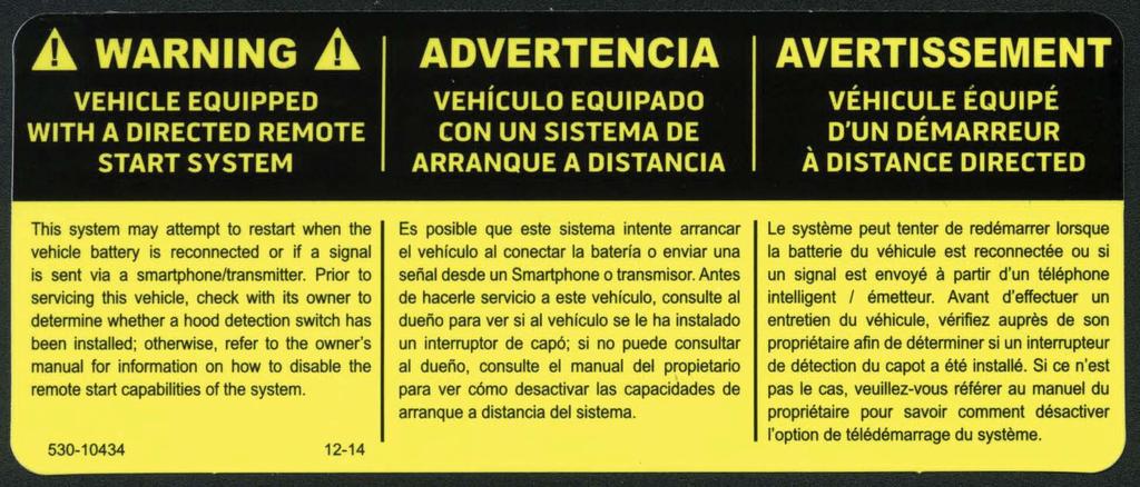
77
78
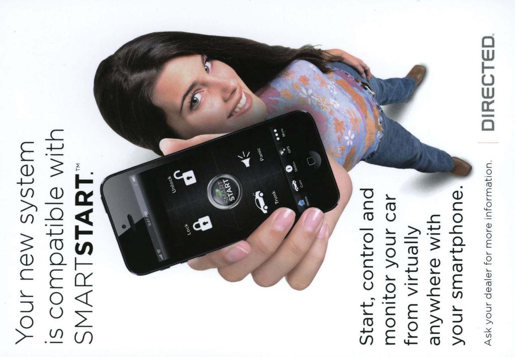
79
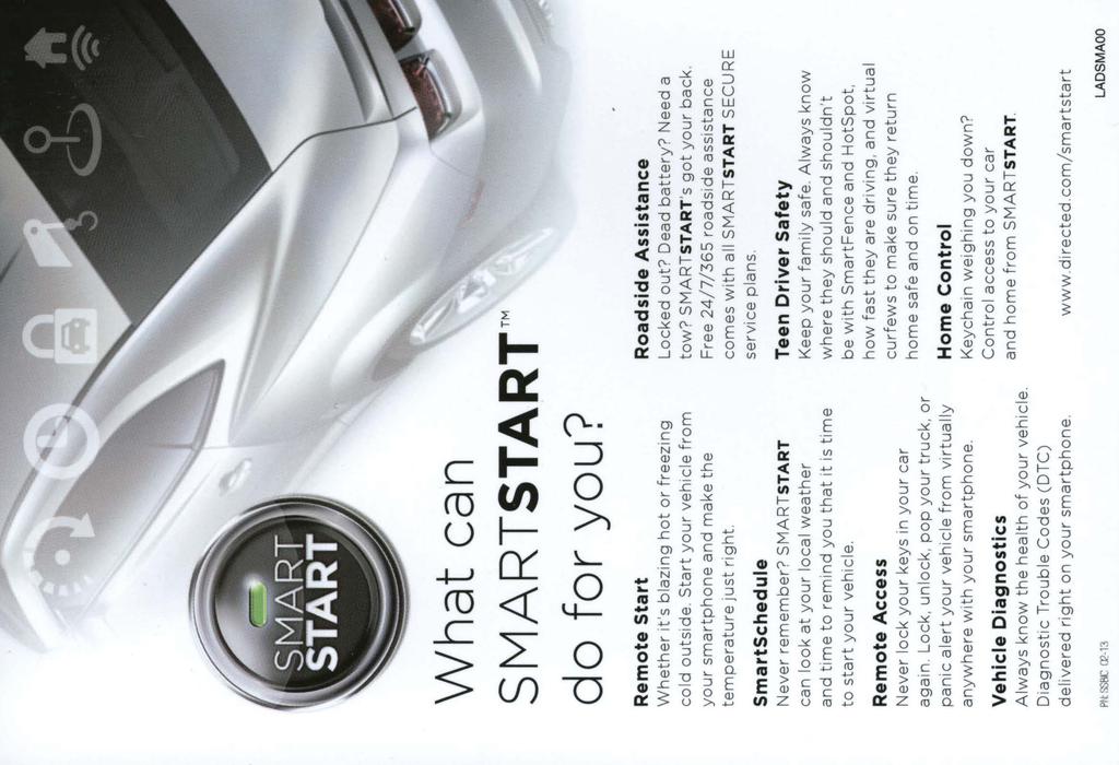
80
Models 5305V, 5305P 5305X, 5305A 5305L. Owner's Guide
 Models 5305V, 5305P 5305X, 5305A 5305L Owner's Guide Congratulations Congratulations on the purchase of your state-of-the-art security/keyless entry and remote start system. Reading this Owner s Guide
Model 5000 Owner's Guide
 Model 5000 Owner's Guide This device complies with part 15 of FCC rules. Operation is subject to the following two conditions: (1) This device may not cause harmful interference, and (2) This device must
Models 5105V, 5105P 5105X, 5105A 5105L. Owner's Guide
 Models 5105V, 5105P 5105X, 5105A 5105L Owner's Guide Congratulations Congratulations on the purchase of your state-of-the-art security/keyless entry and remote start system. Reading this Owner s Guide
MODEL 550HF OWNER'S GUIDE
 MODEL 550HF OWNER'S GUIDE Table of Contents System Maintenance.................................................. 3 Your Warranty........................................................ 3 What Is Included......................................................
CA 6550 Owner s Guide
 PROFESSIONAL SERIES CA 6550 Owner s Guide 2 Way LCD Vehicle Security and Remote Start System IMPORTANT NOTE: The operation of the Security and Convenience System as described in this manual is applicable
MEGA WAY LCD 4-CHANNEL CAR ALARM SECURITY SYSTEM. Operation Manual MEGATRONIX CALIFORNIA, USA MEGA 2500 OPERATE 1
 MEGA 2500 2-WAY LCD 4-CHANNEL CAR ALARM SECURITY SYSTEM Operation Manual MEGATRONIX CALIFORNIA, USA MEGA 2500 OPERATE 1 OPERATION: A. TRANSMITTER OPERATION: Transmitter Button System Function Remark Lock
ca 1553 Owner s Guide
 PROFESSIONAL SERIES ca 1553 Owner s Guide Deluxe Vehicle Security and Keyless Entry System with 2 Way Confirming LCD Remote Control IMPORTANT NOTE: The operation of the Security and Convenience System
CA 650 Owner's Manual
 Remote Vehicle Control System CA 650 Owner's Manual Vehicle Security and Remote Start System with Two Way Confirming LCD Remote Control IMPORTANT NOTE: The operation of the Security and Convenience System
Remote Start Keyless Entry Model 1.3X Owner s Guide
 Remote Start Keyless Entry Model 1.3X Owner s Guide 2011 Directed Electronics, Vista, CA G4202X 2011-03 Contents Government regulations... iii Warning! Safety first... v What s included...1 Important
Owner s Guide. ca6553 ca6553sst
 PROFESSIONAL SERIES Owner s Guide For Models: ca6553 ca6553sst Deluxe Vehicle Security and Remote Start System with 2 Way Confirming LCD Remote Control IMPORTANT NOTE: The operation of the Security and
MEGA WAY LCD 4-CHANNEL CAR ALARM SECURITY SYSTEM. Operation Manual MEGATRONIX CALIFORNIA, USA MEGA 2500 OPERATE 1
 MEGA 2500 2-WAY LCD 4-CHANNEL CAR ALARM SECURITY SYSTEM Operation Manual MEGATRONIX CALIFORNIA, USA MEGA 2500 OPERATE 1 MEGA 2500 OPERATE 2 OPERATION: A. TRANSMITTER OPERATION: Transmitter Button System
5000-series Security and Remote Start System. Owner's Guide
 5000-series Security and Remote Start System Owner's Guide Congratulations Congratulations on the purchase of your state-of-the-art security and remote start system. Reading this Owner s Guide prior to
Owner s Guide CARS & CA2LCD5
 PROFESSIONAL SERIES Owner s Guide For Models: CARS & CA2LCD5 Deluxe Vehicle Remote Start and Keyless Entry System IMPORTANT NOTE: The operation of the Security and Convenience System as described in this
CA 170 Owner's Manual
 Remote Vehicle Control System CA 170 Owner's Manual Vehicle Security System with Two Way Confirming LCD Remote Control IMPORTANT NOTE: The operation of the Security and Convenience System as described
Owner s Guide PROCOMP
 professional series Owner s Guide PROCOMP Deluxe Vehicle Security and Remote Start System with 900 Mhz 2 Way Confirming OLED Remote Control IMPORTANT NOTE: The operation of the Security and Convenience
PROOF OF PURCHASE WILL BE REQUIRED FOR WARRANTY SERVICE OF THIS PRODUCT.
 Model SR9000 Owner s Guide limited lifetime consumer warranty This Ungo Pro Security system is warranted against defects in material and workmanship. The main unit is covered by this limited lifetime warranty.
Owner s Guide CARS & CA4B5
 PROFESSIONAL SERIES Owner s Guide For Model: CARS & CA4B5 Deluxe Vehicle Remote Start and Keyless Entry System IMPORTANT NOTE: The operation of the Security and Convenience System as described in this
MEGA WAY LCD PAGER ALARM WITH REMOTE ENGINE STARTER. Operation Manual MEGATRONIX CHATSWORTH, CA U.S.A. MEGA 2700 OPERATE 1
 MEGA 2700 2-WAY LCD PAGER ALARM WITH REMOTE ENGINE STARTER Operation Manual MEGATRONIX CHATSWORTH, CA U.S.A. MEGA 2700 OPERATE 1 2 WARNINGS: As with any product that performs automatic functions, there
Owner s Guide. ca6554
 PROFESSIONAL SERIES Owner s Guide For Models: ca6554 Deluxe Vehicle Security and Remote Start System with 2 Way Confirming LCD Remote Control IMPORTANT NOTE: The operation of the Security and Convenience
Responder LC Model 5901 Security and Remote Start Owner s Guide
 Responder LC Model 5901 Security and Remote Start Owner s Guide 2008 Directed Electronics, Vista, CA G5702V 2008-08 Contents Government regulations...5 Warning! Safety first...7 What is included...10
ca 5550SST Owner s Guide
 PROFESSIONAL SERIES ca 5550SST Owner s Guide Deluxe Vehicle Remote Start System with 900Mhz 2 Way Confirming LCD Remote Control IMPORTANT NOTE: The operation of the Security and Convenience System as described
Owner s Guide. ca6154
 PROFESSIONAL SERIES Owner s Guide For Models: ca6154 Deluxe Vehicle Security and Remote Start System IMPORTANT NOTE: The operation of the Security and Convenience System as described in this manual is
2005 directed electronics, inc.
 Model 5000 Owner s Guide limited lifetime consumer warranty Directed Electronics, Inc. ("Directed") promises to the original purchaser to repair or replace with a comparable reconditioned model any Directed
Model AS-9234E. Owners Guides
 Model AS-9234E Owners Guides This unit is capable of 3 installation methods. Select the guide for your customer that matches the installation in their particular vehicle. PATENTED: www.voxxintlcorp.com/company/patents
Owner s Guide CASECRS & CA2LCD5
 PROFESSIONAL SERIES Owner s Guide For Models: CASECRS & CA2LCD5 Deluxe Vehicle Security and Remote Start System IMPORTANT NOTE: The operation of the Security and Convenience System as described in this
Model 1601 Security and Remote Start Owner s Guide
 Model 1601 Security and Remote Start Owner s Guide 2008 Directed Electronics, Vista, CA G5102P 2008-06 Contents Government regulations...5 Warning! Safety first...7 What is included...10 Important information...10
2006 directed electronics all rights reserved
 Model 990 Owner s Guide limited lifetime consumer warranty Directed Electronics ("Directed") promises to the original purchaser to repair or replace with a comparable reconditioned model any Directed unit
2005 directed electronics all rights reserved
 Model 4300 Owner s Guide limited lifetime consumer warranty For a period of one calendar year from the date of purchase of this auto-security device, Directed Electronics, Inc. promises to the ORIGINAL
Model PRO-9675FT4 Owner's Manual
 Model PRO-9675FT4 Owner's Manual 4 Button Remote Start Security System With Plug-In Shock Sensor & Starter Disable FEATURES : w 2 Four Button Programmable RF Transmitters w Four Channel Code Learning Receiver
Responder LC Model 5501 Remote Start Keyless Entry Owner s Guide
 Responder LC Model 5501 Remote Start Keyless Entry Owner s Guide 2008 Directed Electronics, Vista, CA G4702V 2008-08 Contents Government regulations...4 Warning! Safety first...5 What s included...8 Important
Model PRO-9775T Owner's Manual 4 Button Remote Start Security System With Plug-In Shock Sensor & Starter Disable
 Model PRO-9775T Owner's Manual 4 Button Remote Start Security System With Plug-In Shock Sensor & Starter Disable FEATURES:! 2 Four Button Programmable RF Transmitters! Four Channel Code Learning Receiver
Owner s Guide APS596Z
 Owner s Guide For Models: APS596Z Security / Keyles Entry System IMPORTANT NOTE: The operation of the Security and Convenience System as described in this manual is applicable to most vehicles. However,
Owner s Guide CA2LCD5
 PROFESSIONAL SERIES Owner s Guide For Model: CA2LCD5 AS9234E RF Upgrade Kit IMPORTANT NOTE: The operation of the Security and Convenience System as described in this manual is applicable to most vehicles.
A U T O M A T I C T R A N S M I S S I O N M U L T I - C H A N N E L T W O - W A Y L C D R E M O T E S T A R T E R AS-2510 TW.
 A U T O M A T I C T R A N S M I S S I O N M U L T I - C H A N N E L T W O - W A Y L C D R E M O T E S T A R T E R S Y S T E M AS-2510 TW User Guide Transmitter Part Number and Module Serial Number...2
CA 180 Owner's Manual
 Remote Vehicle Control System CA 180 Owner's Manual Deluxe Vehicle Security System with Two Way Confirming Dot Matrix Remote Control IMPORTANT NOTE: The operation of the Security and Convenience System
AS-1271/ AS-1272 AS-1271U/ AS-1272U
 MANUAL / AUTOMATIC TRANSMISSION MULTI-CHANNEL REMOTE STARTER SYSTEM AS-1271/ AS-1272 AS-1271U/ AS-1272U User Guide WARNING! It is the responsibility of the vehicle operator to ensure their vehicle is parked
Model 4103XV Remote Start Owner s Guide
 Model 4103XV Remote Start Owner s Guide 2009 Directed Electronics, Vista, CA G4103V 2009-07 Contents Government Regulations...ii Warning! Safety first... iii What is Included...1 Important Information...1
Owner's Manual. Remote Security and Convenience System INS0866 8/98
 Remote Security and Convenience System Owner's Manual IMPORTANT NOTE: The operation of the SURESTART as described in this manual is applicable to most vehicles. However, due to the engine type and configuration
AS-1774 / 1774U. User Guide 5-BUTTON AUTOMATIC / MANUAL TRANSMISSION REMOTE STARTER
 5-BUTTON AUTOMATIC / MANUAL TRANSMISSION REMOTE STARTER AS-1774 / 1774U User Guide WARNING! It is the responsibility of the vehicle operator to ensure that their vehicle is parked in a safe and responsible
TWO-WAY LCD AUTOMATIC TRANSMISSION REMOTE STARTER. User Guide
 TWO-WAY LCD AUTOMATIC TRANSMISSION REMOTE STARTER User Guide A note concerning the battery inside the transmitter: Depending on your usage of the transmitter, the battery can last anywhere between 3 to
Owner s Guide PR1BZ PR1BZLR
 Owner s Guide For Models: PR1BZ PR1BZLR PRORS RF Upgrade Kit IMPORTANT NOTE: The operation of the Security and Convenience System as described in this manual is applicable to most vehicles. However, due
2008 directed electronics
 Responder 350 Owner s Guide Limited lifetime consumer warranty Directed Electronics ("Directed") promises to the original purchaser to repair or replace with a comparable reconditioned model any Directed
Model PRO-9776 Owner s Manual
 4 Button Remote Start Security System With Plug-In Shock Sensor & Starter Disable FEATURES: 2 Four Button Programmable RF Transmitters Seven Channel Code Learning Receiver (capable of accepting 4 transmitters)
Model APS-510E 5 Button Remote Security System with Dual Stage Shock Sensor Owners Guide
 Table Of Contents: Model APS-510E 5 Button Remote Security System with Dual Stage Shock Sensor Owners Guide Features and Options Page 2 About Your "Code Hopping" Transmitters Page 3 Arming Your System
Owner s Guide CA 5055
 PROFESSIONAL SERIES Owner s Guide For Model: CA 5055 Vehicle Remote Start and Keyless Entry System IMPORTANT NOTE: The operation of the Security and Convenience System as described in this manual is applicable
2006 directed electronics
 1002 Model Owner s Guide limited lifetime consumer warranty Directed Electronics ("Directed") promises to the original purchaser to repair or replace with a comparable reconditioned model any Directed
Model APS-596 Owner s Manual
 Model APS-596 Owner s Manual 4 Button Remote Security System with Dual Stage Shock Sensor IMPORTANT! In order to provide the highest possible level of security to your vehicle, this system is equipped
Model PRO 9649 Owner s Manual
 Model PRO 9649 Owner s Manual 3 Button Remote Security System with Starter Disable, & Keyless Entry IMPORTANT! In order to provide the highest possible level of security to your vehicle, this system is
Owner s Guide. ca5354
 PROFESSIONAL SERIES Owner s Guide for models: ca5354 Deluxe Vehicle Remote Start System with 900Mhz 2 Way Confirming LED Remote Control IMPORTANT NOTE: The operation of the Security and Convenience System
Model 553T Owner's Guide
 Model 553T Owner's Guide Limited Lifetime Consumer Warranty For a period of one calendar year from the date of purchase of this auto-security device, Directed Electronics, Inc. promises to the ORIGINAL
Model: APS-610a Owner s Manual 4 Button Remote Security System with Dual Stage Shock Sensor
 Model: APS-610a Owner s Manual 4 Button Remote Security System with Dual Stage Shock Sensor IMPORTANT! In order to provide the highest possible level of security to your vehicle, this system is equipped
" MANUALLY OVERRIDING YOUR SYSTEM
 Model PRO 2000aS Owner s Manual 3 Button Remote Security System with Keyless Entry IMPORTANT! In order to provide the highest possible level of security to your vehicle, this system is equipped with selectable
Remote Vehicle Control System CA-150. Owner's Manual. Vehicle Security System With Remote Keyless Entry
 Remote Vehicle Control System CA-150 Owner's Manual Vehicle Security System With Remote Keyless Entry IMPORTANT NOTE: The operation of the Security and Convenience System as described in this manual is
CA 5053 Owner s Guide
 PROFESSIONAL SERIES CA 5053 Owner s Guide Remote Start and Keyless Entry System IMPORTANT NOTE: The operation of the Security and Convenience System as described in this manual is applicable to most vehicles.
Model AS-9234 Owners Guide Upgrade Vehicle Security & Remote Start System
 Table Of Contents: Model AS-9234 Owners Guide Upgrade Vehicle Security & Remote Start System Features Options Page 2 Page 2 Arming the System - Active Page 3 Arming the System - Passive (Automatic) Page
Model AX-510 Owner s Manual
 Model AX-510 Owner s Manual 4 Button Remote Security System with Dual Stage Shock Sensor IMPORTANT! In order to provide the highest possible level of security to your vehicle, this system is equipped with
CA611 Owners Manual CAUTION!
 CA611 Owners Manual CAUTION! Be certain that the vehicle is outdoors before using this or any remote vehicle starting device. A running engine produces dangerous carbon monoxide fumes which can be harmful
NO ONE DARES COME CLOSE OWNER S GUIDE 5606V
 NO ONE DARES COME CLOSE OWNER S GUIDE M O D E L 5606V Congratulations Congratulations on the purchase of your state-of-the-art remote start and security system. Reading this Owner s Guide prior to using
AS-RFK2315. User Guide. Two-Way FM LED Remote System. Available functionalities depend on vehicle. Consult your dealer for more information.
 Two-Way FM LED Remote System AS-RFK2315 User Guide Available functionalities depend on vehicle. Consult your dealer for more information. Designed & engineered in Canada INDUSTRY CANADA USER NOTICE: Operation
Responder One Remote Start Owner's Guide
 Responder One Remote Start Owner's Guide 2008 Directed Electronics, Vista, CA G4203V 2008-09 Contents Government Regulations...5 Warning! Safety first...7 What is Included...9 Important Information...9
Owner s Guide APS997Z
 Owner s Guide For Models: APS997Z Security / Remote Start Syatem IMPORTANT NOTE: The operation of the Security and Convenience System as described in this manual is applicable to most vehicles. However,
Owner s Guide PE2LCDZ PE1M2LCDZ
 Owner s Guide For Models: PE2LCDZ PE1M2LCDZ APSRS RF Upgrade Kit IMPORTANT NOTE: The operation of the Security and Convenience System as described in this manual is applicable to most vehicles. However,
4105A OWNER'S GUIDE MODEL. Vista, CA 92081
 Vista, CA 92081 The company behind AUTOMATE Auto Security and Remote Start Systems is Directed. Since its inception, Directed has had one purpose, to provide consumers with the finest vehicle security
AL-100DP Full-Feature Vehicle Security System for Factory-Equipped Remote Keyless Entry Transmitters Owner s Guide
 This device complies with FCC Rules part 15. Operation is subject to the following two conditions, (1) This device may not cause harmful interference and, (2) This device must accept any interference that
TWO-WAY LED AUTOMATIC TRANSMISSION REMOTE STARTER. User Guide WARNING
 TWO-WAY LED AUTOMATIC TRANSMISSION REMOTE STARTER User Guide WARNING It is the responsibility of the vehicle operator to ensure their vehicle is parked in a safe and responsible manner. 1. When leaving
Responder LE Model 872 Security and Remote Start Owner s Guide
 Responder LE Model 872 Security and Remote Start Owner s Guide 2008 Directed Electronics, Vista, CA Limited lifetime consumer warranty Directed Electronics. ( Directed ) promises to the original purchaser
2004 Directed Electronics, Inc.
 Avital 2300 Owner's Guide Limited Lifetime Consumer Warranty For a period of one calendar year from the date of purchase of this auto-security device, Directed Electronics, Inc. promises to the ORIGINAL
2005 directed electronics, inc.
 Model 480XV Owner s Guide limited lifetime consumer warranty Directed Electronics, Inc. ("Directed") promises to the original purchaser to repair or replace with a comparable reconditioned model any Directed
4003L OWNER S GUIDE IT'S YOUR CAR - CONTROL IT FROM THE START. The company behind Avital Auto Security Systems is Directed.
 The company behind Avital Auto Security Systems is Directed. Since its inception, Directed has had one purpose, to provide consumers with the finest vehicle security products and accessories available.
Model PRO 9233N OWNER S MANUAL
 Model PRO 9233N OWNER S MANUAL KEYLESS ENTRY ALARM UPGRADE MODULE Congratulations on your purchase of this automotive Keyless Entry Upgrade Alarm System. This system is a state - of - the - art auto security
RF-51-eDp. Operation guide. Deluxe 2-way Oem Upgrade & Range extender. July 22, 2014
 RF-51-eDp Deluxe 2-way Oem Upgrade & Range extender July 22, 2014 Operation guide Man nuales En Español Table Of Contents Controller & Transmitter Overview... 3 The 2-Way Controller... 3 The 1-Way Transmitter...
Model 550ESP Owner's Guide
 Model 550ESP Owner's Guide 1999 Directed Electronics, Inc. Limited Lifetime Consumer Warranty Directed Electronics, Inc. ("DEI ") promises to the original purchaser to repair or replace with a comparable
User Guide TWO-WAY LED AUTOMATIC/MANUAL TRANSMISSION REMOTE STARTER WITH FULL ALARM SYSTEM
 TWO-WAY LED AUTOMATIC/MANUAL TRANSMISSION REMOTE STARTER WITH FULL ALARM SYSTEM User Guide WARNING It is the responsibility of the vehicle operator to ensure their vehicle is parked in a safe and responsible
Owner s Guide. ca5154
 PROFESSIONAL SERIES Owner s Guide for models: ca5154 Automatic / Manual Transmission Remote Start and Keyless Entry System IMPORTANT NOTE: The operation of the Security and Convenience System as described
OWNER'S MANUAL. for AL-1000-E
 OWNER'S MANUAL for AL-1000-E This device complies with FCC Rules part 15. Operation is subject to the following two conditions, (1) This device may not cause harmful interference and, (2) This device must
Model CSI-300 Owner s Manual
 Model CSI-300 Owner s Manual 4 Button Remote Security System with Dual Stage Shock Sensor IMPORTANT! In order to provide the highest possible level of security to your vehicle, this system is equipped
Model 727T Owner s Guide
 Model 727T Owner s Guide limited lifetime consumer warranty Directed Electronics, Inc. promises to the original purchaser to repair or replace with a comparable reconditioned model any Directed Electronics,
3105X O WNER S GUIDE M O D E L. The company behind Clifford Auto Security Systems is Directed.
 Vista, CA 92081 www.directed.com The company behind Clifford Auto Security Systems is Directed. Since its inception, Directed has had one purpose, to provide consumers with the finest vehicle security
Owner s Guide CA 1155
 PROFESSIONAL SERIES Owner s Guide For Model: CA 1155 Vehicle Security and Keyless Entry System IMPORTANT NOTE: The operation of the Security and Convenience System as described in this manual is applicable
ca1153 Owner s Guide
 PROFESSIONAL SERIES ca1153 Owner s Guide Vehicle Security and Keyless Entry System IMPORTANT NOTE: The operation of the Security and Convenience System as described in this manual is applicable to most
Owner s Guide CA 1055
 PROFESSIONAL SERIES Owner s Guide For Model: CA 1055 Vehicle Security and Keyless Entry System IMPORTANT NOTE: The operation of the Security and Convenience System as described in this manual is applicable
2005 Directed Electronics all rights reserved
 Model 160XV Owner's Guide Limited Lifetime Consumer Warranty Directed Electronics promises to the original purchaser to repair or replace with a comparable reconditioned model any Directed Electronics
Model APS-875 Owner s Manual
 Model APS-875 Owner s Manual 4 Button Remote Start Security System With Plug-In Shock Sensor & Starter Disable IMPORTANT! In order to provide you with the highest level of security to your vehicle, this
Owner s Manual. Model: X4. For Technical Assistance, please call (800) , or visit
 , or visit") Owner s Manual Model: X4 For Technical Assistance, please call (800) 638-3600, or visit www.magnadyne.com 2 Congratulations on your purchase of a quality Marksman automotive security system. Marksman security
Owner s Manual Model: X4 For Technical Assistance, please call (800) 638-3600, or visit www.magnadyne.com 2 Congratulations on your purchase of a quality Marksman automotive security system. Marksman security
CA 5054 Owner s Guide
 PROFESSIONAL SERIES CA 5054 Owner s Guide Remote Start and Keyless Entry System IMPORTANT NOTE: The operation of the Security and Convenience System as described in this manual is applicable to most vehicles.
TWO-WAY LED MANUAL / AUTOMATIC TRANSMISSION REMOTE STARTER. User Guide WARNING
 TWO-WAY LED MANUAL / AUTOMATIC TRANSMISSION REMOTE STARTER User Guide WARNING It is the responsibility of the vehicle operator to ensure their vehicle is parked in a safe and responsible manner. 1. a)
VS 315 DELUXE 4-CHANNEL MOTORCYCLE ALARM. Installation And Operation Manual MEGATRONIX CALIFORNIA, U.S.A. VS 315 1
 VS 315 DELUXE 4-CHANNEL MOTORCYCLE ALARM Installation And Operation Manual MEGATRONIX CALIFORNIA, U.S.A. VS 315 1 VS 315 2 INSTALLATION We recommend insulating all your soldered or crimped connections
CS-2011RS Series III
 CS-2011RS Series III Super Rage Remote Control Alarm & Remote Engine Starting System OPERATION INSTRUCTIONS INTRODUCTION CONGRATULATIONS on your choice of a Super Rage Alarm & Remote Engine Starter by
2004 Directed Electronics, Inc.
 Avital 2200 Owner's Guide Limited Lifetime Consumer Warranty For a period of one calendar year from the date of purchase of this auto-security device, Directed Electronics, Inc. promises to the ORIGINAL
SECURITY SYSTEM REMOTE CAR STARTER
 SECURITY SYSTEM REMOTE CAR STARTER DL 1004 DL1004 : 1-WAY REMOTES: FCC ID : 2ACKU-DL1004 / IC : 12084A-DL1004 ANT-FMH-2W : ANTENNA : FCC ID : 2ACKU-A2W01FM / IC : 12084A-A2W01FM MANUFACTURE: FORTIN MADE
CS-2900DP-FM Infinity DP SERIES II (DATA PORT) 2-Way FM Paging Alarm & Remote Engine Starting System OPERATION INSTRUCTIONS
 2-Way FM Paging Alarm & Remote Engine Starting System OPERATION INSTRUCTIONS") CS-2900DP-FM Infinity DP SERIES II (DATA PORT) 2-Way FM Paging Alarm & Remote Engine Starting System OPERATION INSTRUCTIONS INTRODUCTION CONGRATULATIONS on your choice of the Infinity with 2-Way Data Port
CS-2900DP-FM Infinity DP SERIES II (DATA PORT) 2-Way FM Paging Alarm & Remote Engine Starting System OPERATION INSTRUCTIONS INTRODUCTION CONGRATULATIONS on your choice of the Infinity with 2-Way Data Port
Owner s Guide CA2LCD5
 PROFESSIONAL SERIES Owner s Guide For Model: CA2LCD5 Flashlogic FLRS RF Upgrade Kit IMPORTANT NOTE: The operation of the Security and Convenience System as described in this manual is applicable to most
Responder 350. Installation Guide
 Responder 350 Installation Guide NOTE: This product is intended for installation by a professional installer only! Any attempt to install this product by any person other than a trained professional may
6R / 5-BUTTON SERIES VEHICLE SECURITY SYSTEM
 6R / 5-BUTTON SERIES VEHICLE SECURITY SYSTEM Button 1 Button 2 Button 5 Button 3 Button 4 Standard Features: Two 5-Button Remote Transmitters Status indicator (LED) Valet / override switch Multi-tone siren
OPERATING INSTRUCTIONS
 RS2-G3 ONE BUTTON 2-WAY REMOTE START SYSTEM OPERATING INSTRUCTIONS CONGRATULATIONS on your choice of a Cool Start Remote Engine Starter and Keyless Entry with DP Technology by Crimestopper Security Products
Omega Research and Development, Inc. P. O. Box 508 Douglasville, Georgia 30133
 This device complies with FCC Rules part 15. Operation is subject to the following two conditions, (1) This device may not cause harmful interference and, (2) This device must accept any interference that
2 WAY REMOTE STARTER & ALARM SYSTEM INSTALLATION GUIDE FCC ID NOTICE
 REV. ARS. WAY REMOTE STARTER & ALARM SYSTEM INSTALLATION GUIDE FCC ID NOTICE This device complies with Part 5 of the FCC rules. Operation is subject to the following conditions:. This device may not cause
Owner s Guide CA2LED5
 PROFESSIONAL SERIES Owner s Guide For Model: CA2LED5 AS9234E RF Upgrade Kit IMPORTANT NOTE: The operation of the Security and Convenience System as described in this manual is applicable to most vehicles.
5606X OWNER S GUIDE M O D E L. The company behind Clifford Auto Security Systems is Directed.
 The company behind Clifford Auto Security Systems is Directed. Since its inception, Directed has had one purpose, to provide consumers with the finest vehicle security and accessories available. The recipient
OWNER S GUIDE REMOTE START. Part Number: REV A 2010 HYUNDAI MOTOR AMERICA
 OWNER S GUIDE Part Number: 4280279 REV A 2010 HYUNDAI MOTOR AMERICA REMOTE START REMOTE START OWNER S GUIDE INTRODUCTION Congratulations on your purchase of a Hyundai Remote Start System with Deluxe Vehicle