Wire Harness Installation Instructions Manual #90563
|
|
|
- Sheena Flowers
- 6 years ago
- Views:
Transcription

1 Wire Harness Installation Instructions Manual #90563 For Installing: #10113 Direct Fit Bronco Harness 28 Circuit w/switches

2 Perfect Performance Products, LLC Painless Performance Products Division 2501 Ludelle Street Fort Worth, TX phone fax Web Site: If you have any questions concerning the installation of this harness or having trouble in general, feel free to call Painless Performance Products' tech line at Calls are answered from 8am to 5pm central time, Monday thru Friday, except holidays. We have attempted to provide you with as accurate instructions as possible, and are always concerned about corrections or improvements that can be made. If you have found any errors or omissions, or if you simply have comments or suggestions concerning these instructions, please write us at the address above. Or, better yet, send us a fax at (817) or us at painless@painlessperformance.com. We sincerely appreciate your business. Perfect Performance Products, LLC shall in no event be liable in contract or tort (including negligence) for special, indirect, incidental, or consequential damages, such as but not limited to, loss of property damage, or any other damages, costs or expenses which might be claimed as the result of the use or failure of the goods sold hereby, except only the cost of repair or replacement. Cover photo by: Jon Hanna of ClassicBroncos.com Installation Manual January 13, 2014 Copyright 2008 by Perfect Performance Products, LLC 2
3 CAUTION: BEFORE THE REMOVAL OF YOUR ORIGINAL HARNESS AND/OR THE INSTALL OF YOUR NEW PAINLESS HARNESS, DISCONNECT THE POWER FROM YOUR VEHICLE BY REMOVING THE NEGATIVE OR POSITIVE BATTERY CABLE FROM THE BATTERY.THE BATTERY IS NOT TO BE CONNECTED UNTILL THE PAINLESS HARNESS HAS BEEN INSTALLED AND TESTED. A full color copy of these instructions can be found at If your vehicle has an existing harness, you will want to retain it for the possible re-use of various pigtails & connector housings particular to your application. It may also benefit you later to leave the wiring attached to the blower motor and simply disconnect it from the switch. See Heater Switch connection in this manual. During the removal process, avoid making any unnecessary cuts.included in this kit is a sheet of pre-printed labels, to assist in identifying connections as the existing harness is removed from the vehicle. It s a good idea to document how the original harness is routed as this Painless harness follows most of the same routing. If you do not have an existing harness, the package of terminals included with the harness will enable you to make most of the connections needed. The Sending Unit(s), Brake Warning Switch, and Brake Warning Light must re-use a factory connector. Painless Performance Products recommends you, the installer, read this installation manual from front to back before installing this harness. Due to the variables in modifications that can be done to these Broncos, reading this manual will give you considerable insight on the proper installation of this harness. Only printed wires will have a 900-series number. These 900-series numbers are used to identify various wires and circuits in the wiring diagrams that are a part of these instructions. The majority of those without a number are pre terminated with a connector installed. In the event that there are unused or unconnected wires, the ends of all wires labeled in this instruction manual as POWER or wires printed with B+ in the description, will need to have the ends terminated with an insulated terminal or taped. Doing so will prevent the wires shorting and causing harness failure or fire. 3
4 TABLE OF CONTENTS PAGE # SECTION 8 INTRODUCTION 9 CONTENTS OF THE PAINLESS WIRE HARNESS KIT 10 SMALL PARTS 11 TOOLS NEEDED 11 RE-INSTALLATION GUIDELINES 12 RE-USING FACTORY CONNECTORS 12 Removal of Connectors from the Factory Harness 13 Install Factory Style Terminals 16 FUSEBLOCKS 18 ROUTING 20 Modifications Needed 21 FUSE BLOCK & GLOVE BOX MOUNTING 21 Fuse Block Mounting 23 Glove Box Mounting 23 DASH CONNECTIONS 25 Accessory Wires 27 Flashers & Horn Relay 27 Interior Ground 28 Heater Switch 29 Wiper Switch/Washer Button 31 Cigar Lighter 32 Radio 32 Courtesy/Map Light 33 Ignition Switch 34 Dash Mounted Hazard Switch 35 Brake Warning Light 36 Headlight Switch 38 Dash Label Lights 39 Gauge Cluster 40 Fuel Tank Switch 42 Dash Install 42 Turn Signal Switch 43 Later Columns 44 Mid Year Columns 44 Early Columns 46 Gear Indicator Light 47 Wiper Motor 47 Dome Light 48 Aftermarket Tachometer 49 Dimmer Switch 49 Aftermarket Gauges 52 HARNESS ROUTING THROUGH THE FIREWALL 53 TAIL SECTION 53 Brake Warning Switch 53 Sending Unit(s) 54 Left Tail Light 55 License Plate Light 4
5 55 Right Tail Light TABLE OF CONTENTS (continued) PAGE # SECTION 56 DRIVER SIDE HEADLIGHT SECTION 56 Washer Pump 56 Horn 57 Driver Side Exterior Lights 59 PASSENGER SIDE SECTION 59 Starter Solenoid & Maxi Fuse 62 Voltage Regulator 62 Alternator 65 Passenger Side Exterior Lights 65 ENGINE SECTION 65 Neutral Safety Switch & Reverse Switch 66 Electric Choke 66 Oil Pressure & Temperature Sensor 66 Coil 69 Ignition Module 70 TESTING THE SYSTEM 71 WIRE INDEX 77 OTHER PAINLESS PARTS 81 FUSE BLOCK TEMPLATE DRAWINGS, PHOTOS, & SCHEMATICS PAGE # DESCRIPTION 9 Painless Harness Contents 10 Small Parts 12 Terminal Locking Tang 12 Unpinning a Factory Connector 13 Factory Connector Parts Kit 13 Headlight Switch, Ignition. Switch, Wiper Switch, and Hazard Switch Terminal 13 Dash Label Light Terminal Turn Signal Terminal 14 Brake Warning Light, Brake Warning Switch., Sending Unit(s) Splice 14 Aftermarket Tach. Terminal and Connector 14 Brake Warning Light Socket Contact 14 Jaw Style Crimpers 15 Terminal Straps 15 First Crimp 15 Strap 1 Crimped 15 Insulation Crimp Circuit Fuse Block Cut Away 17 Fuse Block Schematic 17 Auxiliary Fuse Block Schematic 19 Firewall Drawings 21 Harness Modification 22 Fuse Block Mounting 1 5
6 DRAWINGS, PHOTOS, & SCHEMATICS (continued) PAGE # DESCRIPTION 22 Fuse Block Mounting 2 23 Fuse Block Cover 23 U Nut 24 Dash Layouts 26 Relay- 12volt Activated 26 Relay- Ground Activated 28 Interior Ground Schematic 28 Heater Switch 29 Heater Switch Schematic 30 Wiper Switch Pin Out 31 Wiper Switch Schematic 33 Ignition Switch Pin Out 34 Ignition Switch Schematic 34 Hazard Switch Pin Out 35 Brake Warning Light Parts 36 Brake Warning Light Power Connection 37 Headlight Switch Pin Out 37 Gauge & Component Lighting Schematic 38 Dash Label Light Connection 39 Gauge Cluster 40 Gauge Cluster Connections 41 Sending Unit Wires 41 Fuel Tank Switch Schematic 43 Turn Signal Pigtail 43 Turn Signal Connector Locking Tang 44 Late Model Turn Switch Pin Out 45 Adapter Pigtail Cut & Unpinned 45 Turn Signal Connector Terminal Removal 46 Early Connector Swap Pin Out 46 Disconnect Terminals 48 Aftermarket Tachometer Mating Terminals 48 Aftermarket Tachometer Mating Connector 48 Aftermarket Tachometer Connector Pin Out 49 Aftermarket Tachometer Connection 49 Dimmer Switch 50 Powering Aftermarket Gauges 51 Wiring Aftermarket Gauges 52 Split Grommet 53 Brake Warning Switch Connector Pigtail 54 Sending Unit Connector Pigtail 55 Tail Light Connectors 56 Umbrella Zip Tie 57 Washer Pump Location 58 Front Exterior Lighting 59 Maxi Fuse Components 60 Starter Solenoid Wiring 60 Maxi Fuse & Starter Solenoid DRAWINGS, PHOTOS, & SCHEMATICS (continued) 6
7 PAGE # DESCRIPTION 61 Starting System 62 Voltage Regulator 63 Alternator B+ Wiring 64 Externally Regulated Alternator 65 3G Alternator 65 Delco Alternator 67 Ballast Resistor 68 Coil Connections 68 MSD Ignition Connections 69 Coil & Duraspark Connections 70 Testing the System 78 Headlight Switch Schematic 79 Turn Signal Switch Schematic 80 Engine Wiring 81 Fuse Block Template 7
8 INTRODUCTION You have purchased what we at Painless Performance Products believe to be the most up-to-date and accommodating Early Bronco wire harness on the market. It has been designed to allow you, the installer, the cleanest and easiest install possible. The flashers, horn relay and proper fuses have all been pre-installed. Individual components and sections are labeled with printed tags for easy identification. The colors used in this harness are the same colors Ford used during the production of these Broncos. In some instances, a wire color may not match your factory color. This is because the colors were not exactly uniform throughout this time frame. In most cases it was a simple stripe color change. These colors will help you identify the different circuits during installation and later on if additions to the overall system are necessary. This complete wiring system, as well as this instruction manual, has been designed with five major groups incorporated into it: DASH GROUP (main body of the harness) Includes 2 fuse blocks, a group of accessory power wires, 2 flashers, a horn relay, an interior ground connection, and the appropriate wires to connect the following: heater switch, wiper switch, brake switch, ignition switch, hazard switch, headlight switch, turn signal switch, fuel tank switch, dimmer switch, wiper motor, brake warning light, dash label lights, radio, gauge cluster, cigar. lighter, map light, dome light, aftermarket tachometer, a gear indicator light ENGINE SECTION Includes wiring that connects to the following: neutral safety switch, reverse switch, electric choke, oil pressure sending unit, engine coolant temperature sensor, coil, and Duraspark ignition module DRIVER SIDE HEADLIGHT Includes wiring that connects to the following: headlight, left turn signal, park light, ground, washer pump, and horn PASSENGER SIDE FIREWALL OPENING Includes wiring that connects to the following: alternator, voltage regulator, starter solenoid, headlight, right turn signal, park light, and ground TAIL SECTION Includes wiring that connects to the following: brake warning switch, auxiliary fuel sending unit, primary fuel sending unit, left reverse light, left turn/brake/tail, left park light, license plate light, right reverse light, right turn/brake/tail light, right park light With this harness covering so many years, and so many variables in modifications that can be done to the early Bronco, there may be wires that are not needed in your specific application. Harness routing also may differ according to your year model or use of aftermarket components such as gauges, shifters, steering column, etc. 8
 423-9696.")
9 CONTENTS OF THE PAINLESS WIRE HARNESS KIT Refer to the Contents Figure (below) to take inventory. See that you have everything you re intended to have in this kit. If you find that anything is missing or damaged, please contact the dealer where you obtained the kit or Painless Performance at (800) The Painless Wire Harness Kit should contain the following: Main Wire Harness, with the 2 Fuse Blocks wired in and fuses installed. 2 Bag Kits containing: 1) 1 package of 4 Tie Wraps, 7 Tie Wraps, Umbrella Tie Wraps, a Ballast. Resistor, 3 Firewall Grommets, 1 pass through plate grommet, Turn Signal Pig-tail, Firewall Pass-thought Plate 2) a Maxi Fuse, a Maxi Fuse Holder Base and Cover 2 wires rolled bundle labeled Heater Switch/Motor Glove Box and This booklet, P/N Painless Wiring Manual. 2 Parts Boxes containing, Terminals, Splices, Screws, extra fuses etc. Part #10113 will have a wiper switch, headlight switch, and ignition switch. CONTENT FIGURE- All of the parts in the Painless kit 9

10 SMALL PARTS Included with the Painless harness are 2 parts kits, and 2 bag kits. The 2 parts kits contain all the loose piece terminals you should need in order to complete the install of your new Painless harness. The 2 bag kits contain zip ties, grommets, and the Maxi Fuse components. One parts kit contains miscellaneous insulated terminals, fuses, screws, and nuts. The terminals that have a semi-transparent insulation are heat shrinkable to provide a weatherproof connection. These terminals include disconnect, ring, and splice terminals. The other parts kit contains factory style, non-insulated terminals. This parts kit will allow you to re-use certain connectors from your factory harness. Refer to the RE-USING FACTORY CONNECTORS section of this manual for more information on these terminals. One bag kit contains all of the components for Maxi Fuse installation. These parts include the base, cover, fuse, mounting screw and ring terminals. The larger bag contains an assortment of zip ties, several grommets, a ballast resistor, Turn Signal Pigtail, and other parts. The zip ties included with this kit are 4, 7, and an umbrella style, which are to be used in the engine compartment. 10
11 TOOLS NEEDED In addition to your regular hand tools, you will need, at least, the following tools: Crimping Tools* Wire Stripper Test Light or Volt Meter Small (10 amp or less) Battery Charger** *We recommend that you use a quality crimper to avoid over crimping. ** see TESTING THE SYSTEM located on page 70 PRE-INSTALLATION GUIDELINES The installation of your wire harness mainly consists of two parts: The physical routing and securing of the wire harness, wires, and groups. The proper connection of the individual circuits. These two major tasks are not separate steps, but are integrated together. That is, you will route some wires and make some connections, route some more wires and make some more connections. We cannot tell you how to physically route the harness in your Bronco, however, this Painless harness follows much of the same routing the factory harness did. Harness routing also my differ according to your year model or use of aftermarket components such as gauges, shifters, steering column, etc. Harness routing also depends a great deal as the extent you want to secure and conceal the harness. This aspect will be more prominent in the ENGINE SECTION wiring. The best pre-installation practice is to become familiar with the harness by locating each of the 4 harness sections in the following list. A good way to do this is by laying out the wire harness on the floor and identifying each of the SECTIONS. (Whenever a particular harness section or component is referred to in these instructions it is shown all caps : TAIL SECTION.) ENGINE SECTION PASSENGER SIDE FIRE WALL OPENING** DRIVER SIDE HEADLIGHT* TAIL SECTION* *The TAIL SECTION and DRIVER SIDE HEADLIGHT are also grouped together with a label that reads DRIVER SIDE FIRE WALL OPENING **PASSENGER SIDE FIREWALL OPENING is also referred to as PASSENEGR SIDE SECTION in this manual For complete information concerning the individual circuits and wires that make up each harness SECTION, see the WIRE INDEX. 11


12 RE-USING FACTORY CONNECTORS Where ever possible, connectors have been pre-installed on the Painless harness. However, some connectors used on the early Bronco are no longer produced. Connectors are not available in the aftermarket for the following components: Wiper Switch, Ignition switch, Dash Mounted Hazard Switch, Headlight Switch, Dash Label Lights, Brake Warning Switch, and the Sending unit(s) Insulated terminals have been provided pre-installed on the Painless harness for all of the dash mounted switches. These terminals will allow connections to be made to these switches without the use of a connector. Some installers may prefer to re-use the factory connector, instead of using these push on style terminals. Factory style terminals have been supplied to replace the insulated terminals pre-installed on the Painless harness. It is up to the installer to remove the pre-installed insulated terminal, and reinstall the correct terminal in order to re-pin the factory connect onto the Painless Harness if they desire. REMOVAL OF CONNECTORS FROM THE FACTORY HARNESS The factory terminals in the connectors have a locking tang that keeps them from being pulled out from the connector. This tang can be seen in the photo to the right, or can be seen by examining one of the factor style terminals from the parts kit. In order to remove the terminal from the connector, the tang must be flattened down and the terminal pulled from the connector. It is a good idea to write down the wire color going to each location before any wire is removed from the connector. Pin outs are available in this manual, however your own notes may prove to be more valuable to you. Looking at the switch side of the connector you will notice little openings above or below the terminals. This little opening gives you access to the locking tang on the terminal. Insert a small pick, a paper clip, or a thin piece of stiff wire into this opening. Apply a slight amount of pressure to make sure you are as far into the connector as you can go. As the wire is being pushed into the opening, pull the wire from the opposite side of the connector to remove the wire from its location. This procedure can be applied to the removal of the factory connectors for the Wiper Switch, Ignition switch, Dash Mounted Hazard Switch, Headlight Switch, Dash Label Lights 12
 connector(s) will be covered in the")


13 The removal of the Brake Warning Light Socket, the Brake Warning Switch Connector, and the Fuel Sending Unit(s) connector(s) will be covered in the section of this manual pertaining to those components. INSTALLING FACTORY STYLE TERMINALS A parts kit containing the terminals needed to re-use factory connectors have been provided with the Painless harness. This kit, seen in the photo below, is divided into the connectors the terminals are provided for. 13


14 Installation of these terminals, with the exception of the splices shown to the left, requires the use of a jaw type crimper. Painless Performance Products offers part #70900 for crimping non insulated factory style terminals, these crimpers can be seen in the photo below. 14


15 The following group of pictures and set of instructions will walk you through the proper termination procedure for the factory style terminals. Begin by cutting the pre-installed insulated terminal from the wire you wish to reterminate with a factory style terminal. Try not to cut any excess wire when doing this, cut right below the pre-installed terminal. With the insulated terminal removed, strip about ¼ of insulation off of the wire. Insert the wire into the terminal. There are 2 terminal straps on the terminal. For instructional purposes, we will label them 1 and 2. Strap 1 crimps the exposed copper stands of the wire, while strap 2 crimps the wire insulation. Make sure your strip length is long enough to ensure only copper strands are crimped by Strap 1, but make sure it is short enough that only insulation is crimper by Strap 2. The photo above best demonstrates this. Using the appropriate jaw on the crimpers, crimp Strap 1. The appropriate jaw depends on the wire gauge as well as the terminal stiffness,. If you are unsure which jaw to use, you can always start with the biggest and work your way down until you get a tight crimp. With Strap 1 crimped you can move onto crimping the insulation strap, Strap 2. Place Strap 2 into the appropriate jaw of the crimpers. This jaw will be larger than the one used to crimp the first strap. Crimp down on Strap 2 making sure the strap folds downward into the wire, and not overlapping itself, refer to the drawing below. Overlapping could cause problems with the terminal fitting into the factory connector. 15

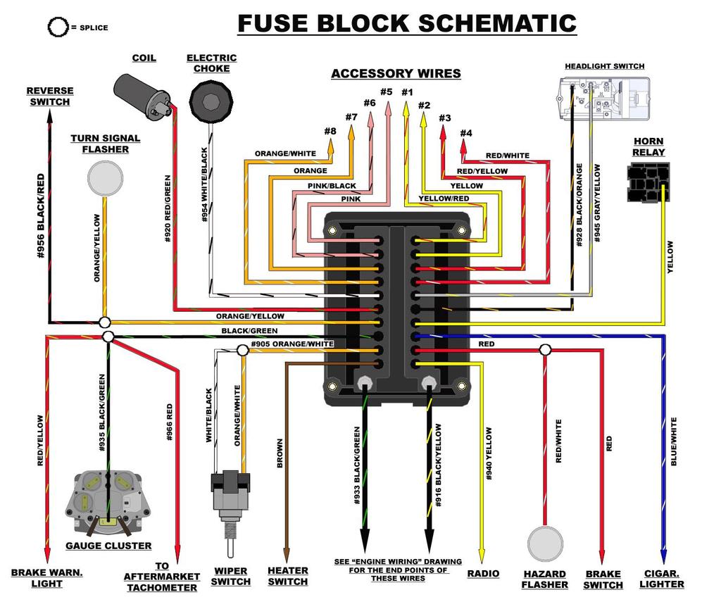
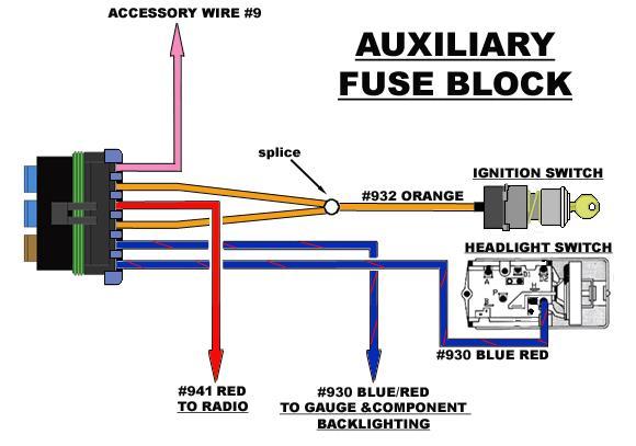
16 FUSE BLOCKS The Painless harness contains 2 covered, weatherproof fuse blocks; One Main, glove box mounted 20 circuit unit, and a smaller 3 circuit auxiliary unit. Both fuse blocks come pre-terminated and installed on the harness. Upon removing the cover of the 20 circuit fuse block you may notice that only about half of the main fuse block comes with fuses pre-installed. The extra, un-fused circuits, allow the installer to power up additional relays, components, and/or switches without tying into a circuit that is already dedicated to another component. The extra circuits have all been pre-wired and simply need to be routed, connected, and fused, more on that in the ACCESSORY WIRE section of this manual. These extra circuits will allow each harness to be custom tailored to each vehicles specific needs. The Fuse label provided with this kit can be used for Fuse identification. You may ask yourself, Why does Painless use an auxiliary fuse block, when there is so much room left in the main fuse block? This is because the main fuse block is all internally bussed, meaning that one power source powers up an entire half, or side, of the fuse block. In the case of this Painless harness, the main fuse block only fuses switched power and constant power. Examine the drawing below for a better understanding of how this fuse block works. The 3 circuit auxiliary fuse block provides fused power to the RADIO and an ACCESSORY WIRE when the Ignition Switch is in the accessory (ACC) position. The 3 rd circuit of this fuse block fuses the power coming from the Headlight Switch out to the gauge illumination. The power going into the Headlight Switch is a 30 AMP fuse, this would be far more than any gauge light bulb would handle. The auxiliary fuse block reduces this 30 AMP output from the Headlight Switch to a more useable 5 AMPS. 20 CIRCUIT CUT AWAY DRAWING 16
17 17
18 ROUTING It is recommended that the main body of this Painless harness, which consists primarily of the dash mounted switch connections, be installed with the dash removed from the vehicle. This will make it easier to view the connections being made as well as giving you, the installer, ample room in which to work. This also allows all connections to be made without removing the switches from the dash, unless you bought a kit and are replacing switches with the new switches provided. When all dash connections have been made, the dash can then be installed into the vehicle. The order in which these instructions are written is based on an install done in this manner. Try to follow these basic guidelines during your install. Routing Guidelines Route the harness away from sharp edges, exhaust pipes, and hood, door, and windshield hinges. Inside edges provide protection from hazards and also provide places for tie wraps, clips and other support. Plan where harness supports will be located. Allow enough slack at places where movement could occur (body to frame, frame to engine, etc.). Use a support about every 12 inches. At wire ends, don t depend on the terminals to support the harness. The weight of the harness could cause terminals to disconnect or copper wire strands to break. Wires should be bundled into groups. Use nylon ties, poly split loom, Power Braid, or tape. Exposed wires of the engine compartment and wires running to the rear of the vehicles may need some sort of wiring loom or covering. This is especially true for vehicles that spend time on off-road trails and/or have their four wheel drive capabilities tested frequently. Painless offers Power Braid Kit part # to fill this need. This kit is specifically designed to fit the Bronco harness and includes everything you will need to add extra protection to your investment. NOTE: Do not route any wire through the firewall at this time. The following information is located at this point in the instruction manual because the modifications required to make routing possible are easier to do before any installation takes place. This harness has been designed to follow the same routing the factory used, regardless of what year Bronco you have. Firewall pass-through holes are the biggest difference in the factory routing during the production run of the Early Bronco. These holes determine how sections (DRIVER SIDE HEADLIGHT SECTION, TAIL SECTION, ENGINE SECTION, and PASSENGER SIDE FIREWALL SECTION) of the Painless harness are routed. See the FIRE WALL DRAWINGS, page 12, for representation of these holes and which sections of the Painless harness pass through each hole. 18
19 FACTORY FIREWALL HOLES: Sections listed are routed through the holes they are pointing to 19
20 MODIFICATIONS NEEDED FOR PROPER ROUTING Certain modifications will need to be made, either to your firewall and/or to the Painless harness, depending on what year Bronco you have. Firewall modifications only need to be made to vehicles that originally had a firewall mounted fuse block. Harness modifications will only need to be made by those who have a hole on the passenger side of their firewall, or for those who decide to cut a hole to avoid routing the starter solenoid, charging system, and passenger side exterior light wires across the firewall. The Painless harness was designed to fit both styles of firewalls; the harness modification could not be avoided. FACTORY FIRE WALL MOUNTED FUSE BLOCK- Firewall Modification Early model Bronco s (1966-early 1971) located the fuse block on the driver s side of the firewall near the accelerator pedal. Two rectangular holes will be left after removal of the factory fuse block. A 3-1/2 (3.5 ) X 3-1/2 (3.5 ) Plate with a 1-1/4 (1.25 ) hole and grommet is supplied with the Painless harness to cover the factory holes and for ENGINE SECTION wiring routing. The strip of metal between the two fuse block holes will need to be cut away in order for the grommet in the block off plate to fit correctly. Using the 4 self tapping screws provided with the parts kit, install the pass through plate over the modified hole. If you do not wish to cut your firewall, the ENGINE SECTION wiring can be routed through an existing hole, however, wire lengths could come up short if done so. Also, it would then be up to the installer to come up with a solution to cover the holes left by the factory fuse block. PASSENGER SIDE FIREWALL HOLE- Painless Harness Modification All Bronco s with a factory glove box mounted fuse block, and the later years of the firewall mounted fuse block, had a pass through hole on the passenger side firewall. The PASSENGER SIDE FIREWALL OPENING section of the Painless harness will need to be re-routed, and zip tied down the main body of the harness towards the fuse blocks. This needs to be so that when the harness is installed this section of the harness will be on the passenger side of the vehicle, not the driver side. See the PAINLESS HARNESS MODIFICATION drawing, page 21, for a visual depiction of this modification. Locate the section of wires labeled PASSENGER SIDE FIREWALL OPENING. Route this section of wires following the length of the main body of the harness towards and past the 2 fuse blocks. This will turn the wires back180 onto themselves, try to avoid folding or pinching the wires where they break out from the main harness. Using zip ties provided with the kit, secure the now re-routed section to the main body of the harness. For those who do not have a hole on the passenger side, but wish to route this section of wires through the dash instead of across the firewall like the factory did, a hole will need to be cut on the passenger side firewall. The grommet supplied with this kit will fit a 1 ½ hole, however if a smaller hole is desired, a new grommet will have to be provided by the installer. 20
21 PAINLESS HARNESS MODIFICATION: this drawing does not show individual wires, only sections Also, this modification only needs to be done by those with a passenger side firewall hole. FUSE BLOCK & GLOVE BOX MOUNTING This Painless harness requires the fuse block to be installed in the glove box or in the general glove box area. A plastic glove box, with all fuse block and glove box mounting holes pre-cut, has been provided to make your install as easy as possible. A template, page 81, has been provided for those who currently have a metal glove box, custom dash, or wish to mount their fuse block in some other through panel way. This template will allow you to accurately cut the holes needed for proper fuse block mounting. FUSE BLOCK MOUNTING Using the 4 supplied large Philips head screws; mount the main fuse block into the side of the glove box. The screws will be inserted through the inside of the glove box and into the fuse block. The fuse block must be positioned with the 2 main lugs towards the back of the glove box. See the FUSE BLOCK MOUNTING 1 & 2 photos for mounting and specific positioning of the fuse block. If the fuse block is not positioned as shown, the wires leaving the fuse block could interfere with the dash mounted speaker. The fuse block cover can be secured to the glove box by running a fuse block mounting screw through the fuse block cover mounting hole, then through the glove box, and then into the fuse block. Some may opt to just cut the fuse block cover mounting tab altogether to keep the cover out of the way when it is off. See the FUSE BLOCK COVER photo for details (page 23). Note: Applying a small amount of a silicone based lubricant on the red seal of the Fuse Block will aid in getting the cover off at a later time after installation. 21


22 FUSE BLOCK MOUNTING 1: Notice the position of the lugs, or studs, coming off the fuse block. FUSE BLOCK MOUNTING 2 22


23 FUSE BLOCK COVER GLOVE BOX MOUNTING After the fuse block has been mounted in the supplied glove box, the glove box will need to be installed onto the dash. Install the glove box over the mounting points of the dash. Notice the mounting points, or metal tabs, of the dash inside the glove box in the FUSE BLOCK MOUNTING 2 photo. (This photo shows 3 of the 5 mounting screws.) U nuts, see photo, have been pre-installed over the glove box mounting holes. Ensure that these nuts are positioned over the center of these holes and that the flat side of the nut is on the inside of the box. The photo of the U nut shows the side that should be on the outside of the glove box. Using the 5 small black Philips head screws from the parts kit, install the glove box. The glove box mounting screws need to be inserted through the metal tabs of the dash and then into the U nut on the Glove box. Loosely install all 5 screws before final tightening. DASH CONNECTIONS The following connections are being listed in the order they break out from the Painless harness. They begin at the Fuse block, on the passenger side, and move across the dash towards the driver side. There are several portions of the Dash Section in the Painless harness that can not be connected until the dash is re-installed in the vehicle. These portions are the BRAKE SWITCH, TURN SWITCH, DIMMER SWITCH, WIPER MOTOR, DOME LIGHT, and possibly 2 wires to the HEATER SWITCH. Connection instructions to these components will come after all other dash components have been installed. There were 3 different main dash configurations used by Ford throughout the early Bronco production run, minor additional changes were made depending on an early or late build date on 1972 models. These changes have been noted in the drawing. The following drawings show these 3 main layouts and the years they apply to. Your dash may or may not have all of the components listed. 23


24 NOTE: Notice the changes made to # s 6, 7, 13, & 15 in
25 ACCESSORY WIRES These wires are located near the Fuse Blocks, they are a large rolled bundle of wire tagged ACCESSORY WIRES. There are 9 wires in all. The ACCESSORY WIRES, allow the installer to power up additional relays, components, and/or switches without tying into a circuit that is already dedicated to another component. This will avoid overloading circuits. All ACCESSORY WIRES are printed with a number and its powered state, switched or B+ (battery constant). ACCESSORY WIRES # 1-8 are pre-terminated to the Main 20 Circuit Fuse Block; ACCESSORY WIRES #9 is pre-terminated to the 3 circuit Auxiliary Fuse Block. These wires can all be seen on the FUSE BLOCK SHEMATICS on page 17. ACCESSORY WIRES #1-4 are all battery constant wires. These wires have constant 12 volt power at all times. ACCESSORY WIRES #5-8 are all switched power wires. These wires only have power when the Ignition switch is in the ON or Run position. ACCESSORY WIRE#9 is a switched power that also has power when the Ignition Switch is in the ACC position. ACCESSORY WIRES #1-4 should be used on your higher amperage components to avoid overloading the switched power circuit coming from the vehicles Ignition Switch. Relays and Switches All ACCESSORY WIRES are 14 gauge and can support up to 30 amps. However, most components requiring this much amperage are better off being connected to a relay. An ACCESSORY WIRE can be used as a 12 volt source activation or 12 volt source for ground activation in these circumstances. Take a look at Painless part # s & to fill your relay needs. A 12 volt activated relay is constantly grounded and will send power out of the output side of the relay to the component being powered when 12 volts is applied to the relay, as the name implies. The 12 volt source can be wired directly to the relay or interrupted by a switch, as shown in the 12 VOLT SOURCE ACTIVATION drawing. Wiring directly to the relay would be used in the case of wiring a Fuel Pump relay or any other high amperage component you would want to run continuously while the key is in the on position. In these cases, make certain the 12 volt wire you are using is a Switched 12 volt wire and not a battery constant. The 12 volt activation wire can also be wired to a switch to offer the user OFF/ON capabilities. These are the situations a battery constant power source would be used. This would allow a component to be turned OFF or ON with out the key in the ON position. However, unless a lighted switch is being used, a ground activated relay may work better to avoid running power through the switch. In the event that a switch is being used, make sure the amperage of the ACCESSORY WIRE does not exceed the capabilities of the switch. 25


26 A ground activated relay is just the opposite of the 12 volt activated relay, 12 volts (battery constant or switched) is supplied uninterrupted and the ground wire is switched. The Horn Relay pre-wired in the Painless harness is a Ground Activated Relay. Another example of this method is a thermostat operated fan relay. In this case however, a thermostatic switch would replace the switch in the drawing below. Like mentioned before, ground activation method is best used when a component is operated by an unlit switch from the interior of the vehicle. 26
27 FLASHERS AND HORN RELAY A TURN SIGNAL FLASHER, A HAZRD FLASHER, and a HORN RELAY have all been pre-installed on your Painless harness. These 3 components are located near the 2 fuse blocks. The 2 flashers simply switch power off and on going to the TURN SIGNAL SWITCH and the HAZARD SWITCH. Power is switched off and on according to heat built in the resistance wire inside the flasher. As soon as power is drawn through the flasher, as when the turn signal or hazard switch is activated, the resistance wire heats up and makes contact with the output side of the flasher. This contact passes power through the flasher, into the switch and out to the turn signal lamp(s). Once this contact has happened, the resistance wire is no longer resisting any voltage, so it begins to cool; this cooling causes the flasher to lose contact. This loss of contact means that there is no longer any voltage going to the switch. Once contact is lost, the resistance wire begins heating up and the entire process starts over again until the turn signal switch or hazard switch is disengaged. The HORN RELAY replaces the factory installed horn relays of the 1972 and later year Broncos, and is a great addition to the units. This relay is ground activated, like the factory horn relay, which means there are no high voltage wires running to the horn button. The horn button now just grounds the relay causing the relay to activate, sending power out to the horn. More on the horn button in the TURN SIGNAL portion of this instruction manual. INTERIOR GROUND The Painless harness contains a single 14 gauge Black wire that is printed with #969 INTERIOR GROUND. This wire provides a single wire hook up for all interior grounds; see the INTERIOR GROUND SCHEMATIC, page 28, for details. If you can t ground to the dash because the dash is built of a non-conductive material (fiberglass) or do not wish to ground to the dash, this step should be skipped until the dash is installed into the vehicle. If this wire is not connected, all gauge back lighting and the horn relay will not work properly. Locate the mentioned Black wire. This wire is located near the Fuse Blocks, Flashers, and Horn Relay Find a good, clean, suitable GROUND that is out of the way of moving parts like cables from the heating controls or hinges of the glove box. Make sure that paint, rust, dirt, or anything else that could hinder a good connection is removed. There are many pre drilled holes following the bottom edge of the dash that make for good locations that are out of the way. Connection of this wire will require a ring terminal from the included parts kit. The size of the ring terminal of course, depends on the size of the bolt or screw you intend to connect through. Route the INTERIOR GROUND wire to the ground location and cut to length, remember to allow slack for harness movement. Install the ring terminal that corresponds to the screw/bolt size you are using and make the GROUND connection. 27


28 HEATER SWITCH Heater switch connection requires 3 wires: 1 Brown (Switched power) 1 Red (LOW or resisted wire) 1 Orange (HI) The Heater Switch portion of the Painless harness consists only of a single Brown wire. The other 2 wires needed to make the proper connections, Red and Orange wires, connect the Heater Switch to the Blower motor. These 2 wires have not been built into this harness, but are provided. These 2 wires can be difficult to access on the blower motor which is why they are not in the main harness. If existing wires are present on your blower motor, it may be easiest to re-use these 2 wires. However, these 2 wires are included as a rolled bundle labeled Heater Switch/Motor for those who wish to replace the wiring, removed it during the un-install of the factory harness, or if none existed to begin with. Make the connections to the heater switch as shown in the HEATER SWITCH SCHEMATIC and/or the HEATER SWITCH photo. The wires used in the above photo were what were previously on the blower motor and not those that are included with the Painless harness. Locate the Brown wire with a single pin black connector pre-installed. This wire will have a tag on it labeled HEATER SWITCH. It is also printed with a circuit number and description, #904 HEATER SWITCH B+. 28

29 Connect this Brown wire to the center prong on the Heater Switch by pushing the connector over the prong. If you are re-using the factory Orange and Red wires connected to the Blower Motor, the following steps will need to be skipped until the dash is re-installed. If you are using the supplied wires from the bag, connect the terminated ends as instructed, or according to the drawing and photo. The decision is up to the installer to connect at the switch now, and connect to the motor when the dash is re-installed, or connect to the motor now, and connect to the switch when the dash is installed. Connect the Orange wire to prong that is counter clockwise to the center prong, in the case of the schematic and photo, the prong on the left. Connect the Red wire to the prong that is clockwise to the center prong, in the case of the schematic and photo, the prong on the right. 29

30 WIPER SWITCH/ WASHER BUTTON Those who purchased Painless Part #10113, a new WIPER SWITCH has been provided with the kit. The bezel and nut from the old switch will need to be re-used. For those with an early Bronco with vacuum wipers and a WASHER BUTTON on the dash, 1966 &1967, jump to the instructions after the WIPER SWITCH SCHEMATIC drawing, next page. Wiper switch connections, for those with electric wipers, are made using the 7 wires tagged WIPER SWICTH. These wires are as followed: o Orange/White- Switched Power Input for the Wiper Motor o White/Black*- Switched Power Input for the Washer Motor o Green*- #983 WASHER MOTOR B+ o Blue- #977 WIPER MOTOR HIGH o White- #979 WIPER MOTOR LOW o Black- #981 WIPER MOTOR PARK o Red- #982 WIPER MOTOR LOW (WASH) *These 2 wires will have 36 of extra length to them. This is to accommodate those who have vacuum wipers and WASHER BUTTON. For the majority of installs these wires can be cut to the same length as the other 5 wires located in the WIPER SWITCH bundle. Terminals have been provided in the parts kit if this decision is made and the Painless installed terminals are cut from the harness. The extra length can also be bundled together and zip tied to the harness. If the extra length is to be retained, avoid bending or folding the wire when the extra length is taken up. Connections to the WIPER SWITCH can be made by either using the terminals that are pre-installed on the harness, or by re-using the factory connector. If a factory connection is desired, make sure you have read the RE-USING FACTORY CONNECTORS portion of this manual before going any further. Locate the wires in the Painless harness tagged WIPER SWITCH Using the WIPER SWITCH PIN OUT and WIPER SWITCH SCHEMATIC drawings, connect the wires according to their proper pin on the switch. Those who opt to use a factory connector, these same drawings will aid in pinning out the factory connector. All drawings in this manual show terminal / wire side views of all switches and connections. 30

31 For those with a 1966 or 1967 Bronco with vacuum wipers and a WASHER BUTTON on the dash, only 2 wires from the WIPER SWITCH portion of the Painless harness will be used; the 2 longer wires. CIGAR LIGHTER Route the White/Black and the Green wire towards the WASHER BUTTON on the dash Connect these 2 wires to the back of the switch. The switch is not polarity specific, meaning either wire can go on either position of the switch. It may be easiest to route this wire now, and make your connections once you get all connections across the dash and GAUGE CLUSTER made. The CIGAR LIGHTER is a simple one wire connection. This wire will be a Blue/White wire tagged CIGAR LIGHTER in the Painless harness. It is also printed with a circuit number and description, #903 CIGAR LIGHTER B+. Locate the CIGAR LIGHTER wire in the Painless harness. This wire breaks out from the harness with the WIPER SWITCH, BRAKE SWICH, HAZARD SWITCH, and several others. This wire has an Insulated socket style terminal pre-installed. Connection of this wire only requires being plugged onto the shaft coming from the back of the CIGAR LIGHTER. To see specifics of this wire, refer to the FUSE BLOCK SCHEMATIC drawing, page
32 RADIO In most cases, the factory radio has been replaced with an aftermarket unit. Connections and wires needed to connect the radio can differ according to the manufacturer. If an aftermarket radio is in place, see the manufacturer s specifications for the connection of the wires in the Painless harness tagged RADIO. In some cases, all 4 wires may not be needed. These 4 wires are: o Yellow- #940 RADIO B+ o Red*- #941 RADIO SWITCHED B+ o Blue/Red- #930 RADIO LIGHTING B+ o Black- #969 RADIO GROUND Specifics of these wires can be found on the FUSE BLOCK and AUXILARY FUSE BLOCK SCHEMATICS (page 17), INTERIOR GROUND SCHEMATIC (page 28), and the GAUGE and COMPONENT BACKLIGHTING SCHEMATIC (page 31) *The factory color of this wire was Yellow/Black, and was the only wire needed for factory RADIO connections. This wire color has been changed to correspond with the color most aftermarket manufacturer s use. For factory radio installs, route the Red wire to the RADIO. The RADIO has a Yellow/Black wire coming off of it. This Red wire, #941, needs to be connected to the Yellow/Black wire on the RADIO. Remember to tape or terminate the ends of any unused B+ wires. COURTESY/MAP LIGHT Some models came equipped with a factory dash mounted COURTESY/ MAP LIGHT. The MAP LIGHT is a fused circuit that its switched by the HEADLIGHT SWITCH. This component is a one wire connection; the Painless harness has a single Black/Blue wire tagged MAP LIGHT with a socket terminal pre-installed to make this connection. Refer to the HEADLIGHT SWITCH SCHEMATIC for the specifics of this circuit, page 78. Locate and route the Black/Blue MAP LIGHT wire towards the MAP LIGHT. Connect the wire to the factory molded male terminal coming off of the MAP LIGHT. If a factory MAP LIGHT is not present, but an aftermarket COURTESY/MAP LIGHT is being used, an additional ground wire may need to be supplied by the installer. The factory lamp grounds itself to the dash which is why a ground isn t present in the Painless harness. 32

33 IGNITION SWITCH Those who purchased Painless Part #10113, a new IGNITION SWITCH has been provided. The bezel and ring from the old switch will need to be re-used. The IGNITION SWITCH is one of, if not the most, important connection in the entire install process. The starting system as well as all components needing switched battery power relies on accurate connections to the IGNITION SWICTH. 5 wires make up this vital portion of the Painless harness, they are: o Yellow- #934 IGNITION SWICH B+ (INPUT) o Black/Green- #933 IGNITION SWITCH B+ (OUTPUT) o Red/Blue- #919 NEUTRAL SAFETY TO IGNITION SWITCH START o Orange- #932 IGNITION SWITCH -ACCESSORY o Pink/White- #968 BRAKE WARN. SWITCH TO IGNITION SWITCH Connections to the IGNITION SWITCH can be made by either using the terminals that are pre-installed on the harness, or by re-using the factory connector. If a factory connection is desired, make sure you have read the RE-USING FACTORY CONNECTORS portion of this manual before going any further. Locate the wires in the Painless harness tagged IGNITION SWITCH Using the IGNITION SWITCH PIN OUT and IGNITION SWITCH SCHEMATIC drawings, connect the wires according to their proper pin on the switch. Those who opt to use a factory connector, these same drawings will aid in pinning out the factory connector. All drawings in this manual show terminal / wire side views of all switches and connections. 33


34 DASH MOUNTED HAZARD SWITCH The Early Broncos had a dash mounted HAZARD SWITCH. In 1973, Ford moved this switch to the steering Column. Those with a 1973 and up column can skip to the next connection; your HAZARD SWITCH will be covered in the TURN SIGNAL portion of this manual. Connections to the HAZARD SWITCH can be made by either using the terminals that are pre-installed on the harness, or by re-using the factory connector. If a factory connection is desired, see RE-USING FACTORY CONNECTORS. Locate the wires in the Painless harness tagged HAZARD SWITCH switch. Using the HAZARD SWITCH PIN OUT and HAZARD SWITCH SCHEMATIC drawings, connect the wires according to their proper pin on the Those who opt to use a factory connector, these same drawings will aid in pinning out the factory connector. All drawings in this manual show terminal / wire side views of all switches and connections. 34

35 Specifics of the HAZARD SWITCH circuits can be seen on the TURN SIGNAL SWITCH SCHEMATIC, page 79. BRAKE WARNING LIGHT The dash mounted BRAKE WARNING LIGHT was not present on the 1966 year models. Those with a 1966 dash can skip to the next connection, the Brake Switch. The BRAKE WARNING LIGHT is a ground activated light. It has a switched power source running to it and is activated through the Brake Warning Switch. The Painless harness has 2 wires tagged BRAKE WARN. LIGHT. The Red/Yellow is a power wire that carries voltage to the lamp socket. This wire can be seen in the FUSE BLOCK SCHEMATIC, GAUGE CLUSTER CONNECTIONS, and the AFTERMARKET GAUGE CONNECTION drawings. The Pink/White wire, printed #968 BRAKE WARN. LIGHT TO BRAKE WARN. SWITCH, is the ground wire/ activation wire that comes from the Brake Warning Switch. This wire is grounded through the Brake Warning Switch either by the Ignition Switch when the key is in the ON position, or is activated by brake line pressure. In order to make the proper connections to the BRAKE WARNING LIGHT, the factory lamp socket, spring, and retainer must be re-used. Begin by cutting the BRAKE WARNING LIGHT off of the factory harness. Make sure you leave enough wire to splice the ground wire to. Notice the length left in the above photo. With the socket removed from the factory harness, remove and discard the factory power wire from the socket. You will need to re-use the factory spring and retainer from the lamp assembly, as shown in the above photo. Connect the Pink/White ground wire of the Painless harness to the factory ground wire coming from the lamp socket. Splices and/or terminals have been provided to make this connection Locate the new bulb contact in the Factory Terminal Parts Kit. These contacts will be small brass terminals. Only 1 contact is needed, however 2 have been supplied in case of a crimp error. The contact can be seen on the BRAKE WARNING LIGHT B+ CONNECTION photo or on page 14. The following series of instructions must be made in order. Refer to the BRAKE WARNING LIGHT B+ CONNECTION photo. 1) Insert the power wire, the Red/Yellow wire, through the lamp socket. 35

36 2) With the wire through the socket, install the spring and then the retainer from the factory assembly. 3) Install and crimp the brass contact terminal onto the wire, AVOID OVER CRIMPING. The crimpers referred to in the RE-USING FACTORY CONNECTORS portion of this manual, provide the best crimp. WARNING LIGHT into the dash. Install the provided bulb into the lamp socket and install the BRAKE HEADLIGHT SWITCH Those who purchased Painless Part #10113, a new HEADLIGHT SWITCH has been provided with the kit. The bezel and nut from the old switch will need to be reused. The HEADLIGHT SWITCH controls several lighting aspects; the main function being of course switching the Headlights off and on. Park and Tail Lights, the Dome and Courtesy Lights, as well as all Gauge Lighting rely on proper HEADLIGHT SWITCH connections. The HEADLIGHT SWITCH SCHEMATIC and GAUGE LIGHTING SCHEMATIC show these circuits. The wires of the Painless harness for HEADLIGHT SWITCH connections will be a group of 6 wires tagged HEADLIGHT SWITCH. These wires are: Red/Yellow- #907 DIMMER SWITCH B+ Brown- #929 PARK/TAIL LIGHT OUTPUT Black/Orange- #928 HEADLIGHT SWITCH B+ Gray/Yellow- #945 DOME LIGHT B+ Black/Blue- Dome light/ Map light output (not printed) Blue/Red- #930 GAUGE LIGHT B+ INPUT Connections to the HEADLIGHT SWITCH can be made by either using the terminals that are pre-installed on the harness, or by re-using the factory connector. If a factory connection is desired, see the RE-USING FACTORY CONNECTORS portion of this manual before going any further. HEADLIGHT SWITCH positions in the dash differ according to year models. The 1966 & 1967 models have the HEADLIGHT SWITCH positioned to the left of the gauge cluster have it positioned to the right of the cluster. For those that have a 1966 or 1967 dash, you may find it easier to route the wires over to the HEADLIGHT SWITCH, but not make your connections until you have made the connections to the Gauge Cluster. 36


37 Those with a dash will find that the group of wires for the HEADLIGHT SWITCH have excessive length to them. This extra length is to accommodate those with a 1966 or 1967 dash. After being routed to the HEADLIGHT SWITCH, this length can be cut from the wires and new terminals installed or the extra length can be bundled and taped or tied to the harness. New terminals have been provided in the parts kit if you opt to cut the wires. Locate the wires in the Painless harness tagged HEADLIGHT SWITCH Using the HEADLIGHT SWITCH PIN OUT and HEADLIGHT SWITCH SCHEMATIC drawings, connect the wires according to their proper pin on the switch. Those who opt to use a factory connector, these same drawings will aid in pinning out the factory connector. All drawings in this manual show terminal / wire side views of all switches and connections. 37

38 DASH LABEL LIGHTS In 1973 Ford started installing label indicators between the Switches and under the Climate Controls on the dash. These labels can be seen in the picture to the left and on the DASH LAYOUT drawing on page 24. If you have a dash, you can skip this step and move on to the next connection, the Gauge Cluster. The DASH LABEL LIGHT circuit can be seen on the GAUGE & COMPONENT LIGHTING SCHEMATIC, on the previous page. Connections to the DASH LABEL LIGHTS can be made by either using the terminals that are pre-installed on the harness, or by re-using the factory connector. The DASH LABEL LIGHT portion of the Painless harness contains 4 wires tagged DASH LABEL LIGHTS. These 4 wires are: 2 Blue/Red- #930 DASH LABEL LIGHTS B+ 2 Black- #969 DASH LABEL LIGHT GROUND Connection only requires routing and connecting 2 wires to each light. Each light requires 1 Blue/ Red, #930, wire, and 1 Black, #969, wire. Either wire can go on either position of the DASH LABEL LIGHT. The DASH LABEL LIGHT connection point can be seen in the below photo. 38


39 DASH LABEL LIGHT CONNECTION GAUGE CLUSTER The GAUGE CLUSTER portion of the Painless harness is made up of 2 break outs. All GAUGE CLUSTER wiring will be tagged with their function ( High Beam Indicator, L. Turn Indicator, R. Turn Indicator, 3 Gauge Light s, Oil Pressure, Temperature, Fuel Gauge, Ammeter, and 2 wires tagged Voltage Regulator. 39
40 All connections to the GAUGE CLUSTER have come pre-terminated and lights have had sockets pre-installed. New Bulbs, provided with the kit, will need to be installed prior to installation. Connection information to the GAUGE CLUSTER are best shown and not described. Using the drawings GAUGE CLUSTER and GAUGE CLUSTER CONNECTIONS, make all connections accordingly. Pay close attention to what you are connecting to ensure you have the correct wire going to the correct position on the gauges, and Voltage Regulator. Schematics pertaining to the lighting can be seen on the INTERIOR GROUND SCHEMATIC (page 28), GAUGE LIGHTING SCHEMATIC (page 37), HEADLIGHT SWITCH SCHEMATIC (page 78), and the TURN SIGNAL SWITCH SCHEMATIC (page 79) If After Market Gauges are being used, either in conjunction with the factory cluster or replacing the cluster, see the AFTERMARKET GAUGE section of this manual. The 2 wires of the AMMETER must be connected even if an AMMETER is not being used your charging circuit will not function, and the Painless harness will have no Power if they are not connected. 40

41 . NOTE: If the Ammeter reads backwards after installation, you have the wrong wire running through the loop. Disconnect the 2 wires and run the Black/Yellow wire through the loop on the GAUGE CLUSTER. FUEL TANK SWITCH The FUEL TANK SWITCH will only be found on those vehicles that came equipped with an Auxiliary Fuel Tank, which became an option in The FUEL TANK SWITCH switched sending unit signals up to the Fuel Level Gauge in the Gauge Cluster. Even though all models did not have this option, the following instructions can not be skipped. The FUEL TANK SWITCH portion of the Painless harness has 3 wires tagged with the description FUEL TANK SWITCH. These 3 wires switch signals from the Fuel Level Sending Units to the Fuel Level Gauge. These 3 wires are: Orange- #939 FUEL GAUGE SIGNAL Orange- #939 FUEL TANK SWITCH TO FUEL SENDING UNIT Yellow/White- #939 FUEL TANK SWITCH TO AUX. FUEL SENDING UNIT 41


42 Notice there are 2 Orange wires with the same #900 number but different descriptions. These 2 wires will need to be connected together using the following instructions for Broncos WITHOUT an Auxiliary Fuel Tank. If this is not done, the Fuel Level Gauge will not work. Both Orange wires come pre-terminated with female insulated terminals. One of the wires will need to have the pre-installed terminal cut off and a male terminal from the parts kit installed. With the new male terminal installed, connect the 2 orange wires together. This will now carry the signal from the sending unit to the gauge without going through the FUEL TANK SWITCH. The Yellow/White wire is not needed. For those with a FUEL TANK SWITCH all three wires, seen in the UNMODIFIED photo above, will be connected using the pre-installed terminals according to the following drawing. Pay close attention to the description printed on the Orange wires and it s location on the switch. 42
43 DASH INSTALL All connections that can be made to the dash have now been made. At this point, the dash must be re-installed into the vehicle in order to proceed with the install. Like mentioned before, several portions of the DASH SECTION of the Painless harness could not be connected until the dash was re-installed in the vehicle. These portions are the BRAKE SWITCH, TURN SWITCH, DIMMER SWITCH, WIPER MOTOR, DOME LIGHT, and possibly 2 wires to the HEATER SWITCH. Instructions on connections of these portions of the Painless harness are listed next. The HEATER SWITCH connection, as described previously in the Heater Switch section of this manual, may need to be connected with the dash in place but before the dash is fully bolted into the vehicle. BRAKE SWITCH The BRAKE SWITCH is located at the top of the brake pedal. This switch requires 2 wires to be connected: a power IN from the fuse block, and a power OUT to the brake lights. The 2 wires, a Red and a Red/Black, needed to make this connection will be tagged BRAKE SWITCH. Locate the BRAKE SWITCH WIRES and route them towards the BRAKE SWITCH. Using the pre-installed terminals, connect both wires to the BRAKE SWITCH. The switch is not polarity specific, meaning either wire can go on either position of the switch. The Red wire is a fused power wire coming from the main 20 circuit fuse block. Specifics of this wire can be seen on the FUSE BLOCK SCHEMATIC, page 17, and the TURN SIGNAL SWITCH SCHEMATIC, page 79. The Black/ Red wire is the output that provides power to the Brake Lights when the brake pedal is pressed. A visual of this wire can be seen on the TURN SIGNAL SWITCH SCHEMATIC. You may be wondering why the Brake Light output connects to the Turn Signal Switch, and not the Brake Lights at the rear of the vehicle. All Early Broncos had what is called Integrated Brake Lights. That means the Brake Lights and Turn Signals share the same filament in a tail light bulb, which is why you only see one wire going to the Tail lights in the TURN SIGNAL SWITCH SCHEMATIC. The other wire to these bulbs can be seen in the HEADLIGHT SWITCH SCHEMATIC. TURN SIGNAL SWITCH Ford used 3 different configurations for the TURN SIGNAL SWITCH. Connectors for all of these switches can be found at the base of the steering column, under the dash. The early production years had 2 connectors; a 6 pin connector and a 2 pin connector. The mid years used a single 8 pin connector, and the later years used a large ¼ circle 11 pin connector. Some Bronco columns have been replaced with tilt columns from Ford trucks. These columns used the same ¼ connector. Connection for each type of TURN SIGNAL SWITCH can be found under the year range listed. A schematic of the TURN SWITCH wires can be found on page79. 43


44 Later model column The Turn Signal Adapter Pigtail included with this kit will need to be used in order to make the connection to the later columns. In order to make this connection, the pigtail must be installed on the Painless harness. Locate the Turn Signal Adapter Pigtail, seen in the photo to the left. Locate the group of wires tagged TURN SWITCH. This group of wires will have a white 8 pin connector installed on them. Plug the Turn Signal Adapter Pigtail into the connector on the TURN SIGNAL ADAPTER PIGTAIL Painless harness. Notice that the pigtail and the Painless harness both have White/Red wires with pre-installed terminals. These 2 wires need to be connected together. This provides power to the column mounted Hazard Switch. If your column has a Gear Indicator Light built into it, refer to the LATER MODEL TURN SWITCH PINOUT drawing and the instructions next to it. With the pigtail installed on the Painless harness, connection to the factory connector on the steering column is now possible. The Yellow wire of the pigtail is not used on these columns. If a factory connection is desired, extra terminals have been provided to remove the white connector from the Painless harness to replace it with the gray connector from the pigtail. Begin by cutting the connector from the group of wires on the Painless harness tagged TURN SWITCH. Also remove the pre-installed terminal on the Red/White wire. This wire is printed #951 TURN SWITCH- HAZARD FLASHER INPUT Remove the gray connector from the Turn Signal Adapter Pigtail. This can be done by pulling the locking tangs away from the terminals. The photo below shows the tangs. Using the factory style terminals provided in the parts kit, terminate the turn signal wires on the Painless harness. Refer to the RE-USING FACTORY CONNECTORS for crimp information. 44

45 Once all wires have been terminated, use the LATER MODEL TURN SWITCH PINOUT drawing to repin the gray connector removed from the pigtail. Notice the mention of the Blue/Red #930 wire in the drawing. This wire can be found in a group of wire tagged GEAR INDICATOR LIGHT. This wire is a power wire for the Gear Indicator Light. Route this wire to the TURN SWITCH connector, terminate with a Turn Signal Switch Terminal, and connect it as shown. At this point the gray connector should now be installed onto the Painless harness. The factory column connector will now plug directly onto the Painless harness without the use of a pigtail. Mid Production Columns No modifications are needed to make the connection to the mid production columns. The connector found on the Painless harness plugs directly onto these columns. Locate the group of wires tagged TURN SWITCH. This group of wires will have a white 8 pin connector installed on them. Plug this connector into the connector on the factory column. The Red/White wire, #951 TURN SWITCH- HAZARD FLASHER INPUT, is not used Early Columns In order for the Painless harness to work with your column, the 2 factory connectors must be replaced with the white 8 pin connector found on the Turn Signal Switch Adapter Pigtail that accompanied this kit. Begin by cutting the connectors from the factory wires coming from the column. Mark the Yellow wire that was originally in the factory 2 pin connector. If it is not marked, it could be confused with the Yellow wire in the 6 pin connector. The Yellow wire in the 2 pin connector is the power output for the left rear Turn/brake light. The yellow wire from the factory 6 pin is a Horn wire. 45


46 Next, remove the 8 pin connector from the pigtail. This can be done one of two ways depending on how the installer wants to connect this 8 pin connector to the factory wiring on the column. You can cut and discard the gray connector off the pigtail, and then splice the 8 pin connector to the wires coming from the column. Or, you can install terminals onto the wires coming out of the column and pin the connector out, creating a factory style connection. The photos below show both methods. If the wires of the Turn Signal Switch Adapter Pigtail were cut, install insulated but splices, like the one found on the Yellow wire, onto the wires coming from the white connector of the adapter pigtail. Using the CONNECTOR SWAP drawing, splice the connector pigtail to the wires on the column. For the most part the colors match the existing wires on your column, except for the 2 Yellow wires. The Yellow wire you marked from the factory 2 pin connector, will need to spliced to the Yellow/Black of the connector pigtail. The text in the drawing represents your factory column wires. If the connector is to be installed on the column, remove the terminals from the 8 pin connector on the Turn Signal Switch Adapter Pigtail. This is done by depressing the locking tang on the terminal and pulling the wire from the connector. Crimp new terminals, provided, onto the wires coming from the steering column. Using the CONNECTOR SWAP drawing, pin out the 8 pin connector to the wires on the column. For the most part the colors of the drawing match the existing wires on your column, except for the 2 Yellow wires. The Yellow wire you marked from the factory 2 pin connector will need to go to the cavity marked Yellow/Black on the drawing. The text in the drawing represents your factory column wires. To ensure you are 46


47 pinning the connector out properly, notice the location of the bulge of the connector in the drawing. The Red/White wire, #951 TURN SWITCH- HAZARD FLASHER INPUT, is not used GEAR INDICATOR LIGHT 2 wires tagged GEAR INDICATOR LIGHT can be found rolled together in the same breakout from the harness as the Turn Switch. These 2 wires are: Blue/Red- #930 GEAR INDICATOR LIGHT B+ Black- #969 GEAR INDICATOR LIGHT GROUND These 2 wires are 6 in length. This is to accommodate those who have installed an aftermarket floor shifter. This will allow for these wires to be routed out the firewall, with the ENGINE SECTION, under the vehicle, and up to the GEAR INDICTAOR LIGHT on the shifter. Some shifters may only require the Blue/Red power wire to be connected as the light may already be grounded to the shifter. Most shifters require the wire be spliced to an existing wire on the GEAR INDICATOR LIGHT. Insulated terminals, like the ones photographed to the left, have been provided in order for you to make this connection, but also be able to unplug the harness from the LIGHT, if the need ever occurs. Install male terminals onto the wire(s) of the GEAR INDICATOR LIGHT. DISCONNECT TERMINALS After the wire(s) from the Painless harness have been routed towards the GEAR INDICATOR LIGHT, install female terminals At this point the light and the Painless harness should have terminals installed and just need to be connected to each other. 47
48 NOTE: Routing the connections to the GEAR INDICATOR LIGHT, may be easier to do when the rest of the ENGINE SECTION is routed through the firewall. WIPER MOTOR The factory pigtail connecting the WIPER MOTOR to the factory harness will need to be reused. The Painless harness has a molded 4 pin connector located at the end of the wires tagged WIPER MOTOR. These 4 wires are: Blue- #977 WIPER MOTOR HIGH White- #979 WIPER MOTOR LOW Black- #981 WIPER MOTOR PARK Red- #982 WIPER MOTOR LOW (WASH) These wires can be seen on the WIPER SWITCH SCHEMATIC on page 23. The following series of instructions explain how to connect the factory WIPER MOTOR pigtail to the Painless harness. DOME LIGHT Locate the 2 molded connectors of the factory WIPER MOTOR pigtail. The pigtail exits the lower driver side windshield frame. The connectors will be 2 pin connectors. Route the 4 pin molded connector on the Painless harness towards the 2 factory connectors. Connection is made by matching the factory colors to the Painless colors. In some instances the colors may not be identical; some factory colors may also include a stripe. For example: the White wire of the Painless harness will connect to the White /Orange wire of the 1977 models. In 1974, Ford began offering a DOME LIGHT as an option. The Painless harness has a single wire, tagged DOME LIGHT, to cover those with this option. This wire is a Black/Blue wire that has a socket style terminal pre-installed. The circuit the DOME LIGHT is part of is detailed in the HEADLIGHT SWITCH SCHEMATIC, page 78. The proper connection procedure for this wire is as follows: Locate the factory wire for the DOME LIGHT. This wire will exit the bottom of the driver side windshield frame with the Wiper Motor wires. This wire will be a Black/Blue wire with a male molded connector installed on it. Route the Black/Blue DOME LIGHT wire from the Painless harness to the Factory Wire. Connect the 2 wires together by installing the socket terminal of the Painless wire over the factory male terminal. If a factory DOME LIGHT is not present, but an aftermarket light is being used, there is not enough length in this wire to reach a DOME LIGHT, a factory style pigtail will need to be made by the installer. It will also be up to the installer to provide a ground wire for the light. 48


49 AFTERMARKET TACHOMETER The Bronco never had a factory tachometer option. Many owners have installed an AFTERMARKET TACH to keep an eye on the engine s RPMs. The Painless harness includes the 4 necessary wires required for AFTERMARKET TACHOMETER installation. These 4 wires are tagged AFTERMARKET TACH. and have a 4 pin flat connector installed on them. These wires are: Blue/Red- #930 AFTERMARKET TACH BACKLIGHT B+ Black- #969 AFTERMARKET TACH BACKLIGHT GROUND Red- #966 AFTERMARKET TACH B+ Green- #923 COIL - TO AFTERMARKET TACH SIGNAL The 4 pin connector, and terminals supplied in the parts kit, allow for a connection to the TACH, instead of hard wiring directly to it. TACH with lugs (no wires): If your TACH has lugs instead of wires coming from the back, wires will need to be installed to the TACH and then terminated on the opposite end with the terminals shown. If you wish to wire directly to the TACH, you can cut the connector from the Painless harness, and attach the wires directly to the TACH according to the manufacturer s instructions. TACH with wires: Begin by routing the TACH wires to reach the connection to the Painless harness and cut to length. Install the mating terminals, seen to the left, onto the wires from the AFTERMARKET TACH. Consult the manufacturer s instructions to determine each wires function. Locate the mating connector from the Parts Kit. This connector can be seen in the photo to the left. This photo shows both ends of the connector. Using the MATING CONNECTOR PIN OUT and AFTERMARKET TACH CONNECTION drawings, pin the mating connector out according to the function they match to the Painless harness. The terminals are inserted into the side of the connector with the 4 perfectly round circles, again, see the photo at the left or the AFTERMARKET TACH CONNECTION drawing When the mating connector has been pinned out with the 4 wires coming from the TACH, connect it to the connector found on the Painless harness. The mating connector can be plugged in 2 ways, make sure the connector is plugged in the correct way. 49

50 DIMMER SWITCH The DIMMER SWITCH connection is made by plugging the 3 pin connector found on the Painless harness into the dimmer switch. This will be a black connector tagged DIMMER SWITCH. Begin by unbolting the DIMMER SWITCH from the floor board. Because this switch is located on the floor, the contacts become dirty and corroded. Using a wire brush, or whatever else is handy, clean the 3 contacts to ensure good connection will be made when the DIMMER SWITCH connector is installed. Route the DIMMER SWICTH wires from the Painless harness to the switch and connect. It will take some pressure to push the connector onto the switch, make sure the connector is a going on straight or the contacts will bend. Once the connector is installed, the DIMMER SWITCH can be bolted back down to the floor. AFTERMARKET GAUGES In some applications, AFTERMARKET GAUGES have replaced the factory gauge cluster or are used in conjunction with the factory cluster. The Painless harness does not have wires intended for specific AFTERMARKET GAUGES; however, all wires and circuits needed for correct installation are present in the harness. 50
51 Most electric AFTERMARKET GAUGES require 5 wire connections: Gauge Power- a Switched 12 volt power source Gauge Ground Signal- from a sensor or sending unit Gauge Light Power- 12 volt power source from the Gauge Lighting circuit Gauge Light Ground Most mechanical AFTERMARKET GAUGES only require 2 wires to be connected: Gauge Light Power- 12 volt power source from the Gauge Lighting circuit Gauge Light Ground All of these connections are already present in the wiring for the factory a Gauge Cluster, with the exception of the Gauge Ground. Additional length may need to be added to some wires, as the wires of the Painless harness have all been pre-cut according to the factory gauge cluster. Gauge power can be supplied to AFTERMARKET GAUGES numerous ways using the Painless harness. The easiest way would be to use the Black/Green wire, printed #935 GAUGE CLUSTER VOLTAGE REGULATOR B+. Refer to the POWERING AFTERMARKET GAUGES drawing below or to the GAUGE CLUSTER CONNETION drawing on page 40. This wire comes from the fuse block and is already fused and designated to power the Gauge circuit. The drawing below shows 2 other wires that come from the same fuse that could be used to power AFTERMARKET GAUGES as well. A switched power Accessory wire, Accessory wires 5-8, could also be used on applications when an AFTERMARKET GAUGE is accompanying the factory cluster. In this case the Black/Green wire could be spliced into to have all gauges on the same circuit. 51

52 On applications where AFTERMARKET GAUGES are replacing the factory Gauge Cluster or a factory Gauge, the sender wires from the Painless harness will work with the new gauge just as it did with the factory gauge. These sensor wires can be seen on the POWERING AFTERMARKET GAUGES drawing on the previous page or on the WIRING AFTERMARKET GAUGE drawing below. Grounds for Gauges are not present in the Painless harness as the factory Gauges grounded themselves through the dash. Unused grounds may be present in the Painless harness if some components were not available or connected during the dash install. A ground source could come from the Radio, Aftermarket Tach, Dash Label Lights, or Gauge Light Sockets. The INTERIOR GROUND SCHEMATIC, page 28, shows possible ground wire sources. Seeing that a good ground source is not hard to find on these vehicles, the installer could run their own ground circuit for gauge connection. Backlight power and ground could come from the Radio, Aftermarket Tach, Dash Label Lights, or Gauge Light Sockets; the same sources mentioned as sources for a Gauge Ground. The GAUGE LIGHTING SCHEMATIC, page 37, shows all the possible sources for power to a Gauge light. 52
, to the drive side exterior lights (DRIVER SIDE HEADLIGHT SECTION), to the engine (ENGINE SECTION), and")
53 HARNESS ROUTING THROUGH FIREWALL At this point in time, the only thing left to do on the interior of the vehicle is route the remainder of the Painless harness out into the engine compartment. From there, depending on the section, it will route to the rear of the vehicle (TAIL SECTION), to the drive side exterior lights (DRIVER SIDE HEADLIGHT SECTION), to the engine (ENGINE SECTION), and to the passenger side exterior lights and starter solenoid (PASSENGER SIDE HEADLIGHT SECTION) Before the install process began you were to make modifications to either your firewall or to the Painless harness to ensure everything exited your firewall according to the firewall configuration to have. If this was not done see the MODIFICATIONS NEEDED FOR PROPER ROUTING section on page 20. At this time route all wires through the firewall. Page 19 has a diagram that depicts which sections route through each hole on the different Bronco firewalls. Some sections have large connectors pre-installed on the harness. In some cases these connectors need to be passed through the hole before the majority of the wire is. This will ensure the connector has enough room to fit through the hole before the opening is filled will wire. When all sections are passed though the firewall, rubber grommets from the parts kit will need to be installed over the harness and into the firewall holes. Locate the 3 grommets included in the parts kit. In some applications, , only one grommet may be used. These three grommets will be installed into the factory holes on the passenger and driver side, as well as the center fire wall hole the Engine Section is coming though. The Engine Section will require the smaller grommet Cut through one side of the grommet(s) like shown in the picture to the right. DO NOT CUT THROUGH BOTH SIDES. This will allow the grommet to be installed over the wires. Install the grommet(s) over the wires exiting the firewall. Install the grommet into the firewall hole, it may take some patience and several attempts as the grommets have a ¼ panel thickness groove and are not as pliable as most grommets. 53


54 TAIL SECTION Begin by locating the TAIL SECTION from the driver side firewall opening. This section will route down the top of the driver side frame rail to the back of the vehicle. Once it reaches the left tail light area, it will need to be routed across the top the fuel tank over to the right tail light. Routing of this section will take place as connections down the frame are made. Loosely zip tie the harness to the frame and surrounding areas as you move back. Begin by routing the harness down the driver side frame until to get to the first break out of the TAIL SECTION, the Brake Warning Switch. BRAKE WARING SWITCH The BRAKE WARNING SWITCH connection requires re-using the original connector and splicing it to the 2 wires of the Painless harness tagged BRAKE WARN SWITCH. These will be 2 Pink/White wires. One wire provides ground to the Brake Warning Light in the dash, and the other wire connects to the ground tab on the Ignition Switch. The BRAKE WARNING SWITCH can be seen on the ENGINE WIRING drawing on page 80. Begin by cutting the factory connector from the original harness; this will create a connector pigtail. Be sure to leave about 2-3 of wire coming from the connector. Strip the ends of the factory wires coming from the connector. This strip needs to be about ¼. Once stripped, install a shrinkable butt splice supplied in the parts kit to both wires. With splices installed on the connector pigtail, plug the connector into the BRAKE WARNING SWITCH. The SWITCH is located on the top part of the driver side frame, behind the shock tower. With the connector installed, route the 2 wires of the Painless harness up to the switch and cut the 2 Pink/White wires to length. Strip the ends of the wires from the Painless harness and splice them to the factory connector using the butt splices you installed on the connector pigtail. This switch is not polarity specific, so it does not matter which wire connects to which. SENDING UNIT(s) The SENDING UNIT connection is the next connection you come to down the frame. For those with an Auxiliary Fuel Tank, the Auxiliary SENDING UNIT is the first 54

55 one you will come to. Connections to the Auxiliary SENDING UNIT are the exact same as connections to the Main SENDING UNIT. The only difference between the two, are the wire colors. The Auxiliary UNIT is a Yellow/White wire, printed #939 FUEL TANK SWITCH TO AUX. FUEL SENDING UNIT; where as the Main UNIT is an Orange wire, printed #939 FUEL TANK SWITCH TO FUEL SENDING UNIT. Vehicles without an Auxiliary tank will not use the Yellow/White wire. Both of these wires can be seen on the FUEL TANK SWITCH SCHEMATIC located on page 35. In order to make connections to the SENDING UNIT(s) the factory molded connector must be re-used. The studs on the UNIT are too small to fit standard bullet type terminals, and are not threaded to allow for a ring terminal and nut to be installed. Begin by cutting the factory connector from the original harness, this will create a connector pigtail be sure to leave about 2-3 of wire coming from the connector. Only cut the SENDING UNIT output wire and not the Black ground wire. This ground wire will be re-used in order to re-connect the ground to its factory location. Strip the end of the factory wire coming from the connector. This strip needs to be about ¼. Once stripped, install a shrinkable butt splice supplied in the parts kit. With a splice installed on the connector pigtail, plug the connector into the SENDING UNIT. The connector is keyed so it will only go on one way. With the connector installed, route the wire of the Painless harness over to the connector pigtail and cut it to length. Strip the end of the wire from the Painless harness and splice it to the factory connector using the butt splice you installed on the connector pigtail. Make sure you re-install the ground wire using the factory screw and mounting hole. Vehicles with an Auxiliary Tank will next need to move to connecting the Main SENDING UNIT in the same manner. LEFT TAIL LIGHT In order to make the following connections, the TAIL LIGHT housing assembly needs to be removed from the vehicle. This requires removing the 2 screws from the lens, and then the 2 screws holding the housing to the body of the Bronco. The LEFT TAIL LIGHT section consists of wires for the REVERSE LIGHT, TURN/BRAKE & TAIL, and PARK LIGHT. With the exception of the reverse lights, all TAIL LIGHT wiring can be seen on the HEADLIGHT SWITCH SCHEMATIC, and the TURN SIGNAL SWITCH schematic. 55

56 Route the LEFT TAIL LIGHT section up into the tail light bucket of the quarter panel. The PARK LIGHT located on the side of the vehicle has a Brown wire with a molded male terminal installed on it. This factory Brown wire will plug into the socket terminal installed on the Brown wire tagged PARK LIGHT on the Painless harness. Not all models will have this PARK LIGHT. The LEFT TAIL LIGHT housing assembly has 2 molded factory connectors on it: a 2 pin male-female Turn/Brake & Tail Light a single male- Reverse Light The photo to the right shows the 2 connections found on the Painless harness that connects to the TAIL LIGHT Housing Assembly. The 2 pin connector tagged TURN/BRAKE/TAIL will plug into the factory 2 pin connector on the TAIL LIGHT housing assembly. Using the pre-installed socket terminal, the Black/Red wire tagged Reverse will plug into the molded male connector. With these 3 connections made to the TAIL LIGHT housing assembly can now be reinstalled. LICENSE PLATE LIGHT Connection to the factory LICENSE PLATE LIGHT is an easy one wire connection. The Painless harness covers this connection by providing a Brown wire tagged PLATE LIGHT. This wire has a pre-installed socket terminal and simply needs to be connected to the molded male connector coming from the factory PLATE LIGHT. This same socket can be seen on the single wire in the above photo. If an Aftermarket Light has replaced the original, it is up to the installer to provide a ground wire for this light as the factory light was grounded to the body. RIGHT TAIL LIGHT The RIGHT TAIL LIGHT connections are the same as those covered in the Left Tail Light portion of this manual, starting on the previous page. The Painless Harness will need to be routed across the top of the Fuel Tank in order to reach the RIGHT TAIL LIGHT. 56

57 DRIVER SIDE HEADLIGHT SECTION Located coming from the driver side firewall hole is the DRIVER SIDE HEADLIGHT SECTION. This section contains the connections for the WASHER PUMP, HORN, LEFT TURN SIGNAL, LEFT HEADLIGHT, GROUND, AND PARK LIGHT. All mentioned connections are tagged and have all terminals and connectors pre-installed. The DRIVER SIDE HEADLIGHT section follows the exact same routing the factory did, above the inner wheel well along the inner fender. Umbrella style zip ties have been provided for you to attach the Painless harness to the inner fender in the same fashion the factory did. UMBRELLA ZIP TIE Route the DRIVER SIDE HEADLIGHT SECTION over the top of the wheel wells. Locate the Umbrella zip ties in the parts kit, half will be for the Driver side of the vehicle and the other half for the Passenger side. Install the Driver side half of the zip ties into the ¼ holes down the inner fender. These are the same holes left behind by the factory plastic retainer loops. With the zip ties installed and the harness routed, wrap the tie around the harness and LOOSELY tie the harness to the fender. Make sure you leave enough room to pull and push the harness as you make your connections. Once all connections are made, tighten the zip ties. NOTE: If you need to remove the Umbrella Zip Tie from the inner fender for any reason, the locking tabs of the Zip Tie can be accessed through the wheel well. WASHER PUMP The WASHER PUMP connection offered in the Painless harness has a connector installed. This connector will only fit the pumps used on the factory Electric Wiper vehicles. The vehicles will have a different style WASHER PUMP unless they have been retro fitted with the later style PUMP. For those with the early style PUMP, your instructions follow the instructions for those with the electric Wiper System PUMP. Connections to the WASHER PUMP, located on the inner fender side at the bottom of the washer reservoir, may be easier to make with the reservoir removed from the vehicle. 57
58 HORN Locate the Black and Green wires tagged WASHER. These 2 wires will be the first breakout of the DRIVER SIDE HEADLIGHT section and will have a connector installed. To see the connector, as well as the opposite ends of these wires, refer back to the WIPER SWITCH SCHEMATIC on page 31. This connector plugs into the WASHER PUMP. Make sure the WASHER PUMP posts and cavity this connector plugs into are clean and free of debris before trying to connect the Painless harness to the WASHER PUMP. If the reservoir was removed, it can now be reinstalled. For those with a WASHER PUMP that was used on the vacuum wiper system. Begin by cutting off the connector preinstalled on the Painless harness The original connector will need to be reused in order to connect to the early style WASHER PUMP. The connector has one Black/White wire going into it. This wire will need to be cut just as the Brake Switch and other re-used connectors have been up to this point. Make sure to leave enough length on this wire to splice to. Only one wire from the WASHER portion of the Painless harness will be used. The Green wire, printed #983 WASHER MOTOR B+, will need to be spliced onto the original wire coming from the factory WASHER PUMP connector. Heat shrinkable splices have been provided in the parts kit. Located below the Washer Reservoir is the HORN. Connection to the HORN is a one wire connection. The Yellow/Green #924 HORN B+ wire of the Painless harness has a single pin connector pre-installed. This Yellow/Green wire is the output wire coming from the Horn relay. Route this wire down to the HORN and connect it to the Input tab found on the HORN. DRIVER SIDE EXTERIOR LIGHTS (PARK LIGHT, HEADLIGHT, LEFT TURN SIGNAL, & GROUND) The DRIVER SIDE EXTERIOR LIGHTS connections are all made with the Painless harness using the pre-installed connectors. Each group of wire of the Painless harness is tagged with its designated component; HEADLIGHT, TURN SIGNAL, PARK LIGHT. The FRONT EXTERIOR LIGHTING drawing on the following page has been provided to show the locations of these LIGHTS. The PARK LIGHT and TURN SIGNAL have the same male/female molded connector installed, the same connector as seen in the TURN/BRAKE/TAIL & REVERSE photo on page 55. Do not get the 2 mixed when making your connections. The PARK LIGHT has Black and Brown wires, whereas the TURN SIGNAL has Green/White and Brown wires. Connect the molded connector on the Painless harness tagged PARK LIGHT to the factory connector coming from the PARK LIGHT. This pigtail can be found coming from driver side inner fender well, near the core support. Some models may not have the front PARK LIGHTS. 58
59 Connect the molded connector on the Painless harness tagged TURN SIGNAL to the factory connector coming from the grille mounted TURN SIGNAL. The HEADLIGHT connector on the Painless harness will be a black 3 pin connector with the flowing wires: o Green/Black- #908 DRIVER SIDE HIGH BEAM o Black- Ground (not printed) o Red/Black- #909 DRIVER SIDE LOW BEAM Connect the connector found on the HEADLIGHT portion of the Painless harness to the three tabs on the back of the headlight. Make sure the connector is going on straight as the tabs may bend. The GROUND connection is made using the factory bolt and hole located on the core support. Route the Black wire tagged GROUND to the same location the factory ground was mounted. A ring terminal has been pre-installed. 59

60 PASSENGER SIDE SECTION Locate the section of wires intended for the PASSENGER SIDE. This group of wires contains connections for the Alternator, Voltage Regulator, Starter Solenoid, Turn Signal, Ground, Headlight, and Park Light. Depending on which firewall hole configuration you have, see page 19, this section will either be coming from the passenger side firewall hole or the driver side firewall hole. Those that have this section coming from the Driver side firewall hole, this section will need to be routed across the top of the firewall, over to the passenger side of the vehicle. The Painless harness will follow the same path and use the same mounting points the factory harness used. For those that have a passenger side firewall hole, this section should already be on the passenger side of the vehicle due to the harness modification done on page 20. With the PASSENGER SIDE section on the Passenger side of the vehicle, route it down the inner fender across the top of the wheel well. Those installing a 3G Alternator, should refer to the 3G instructions on page 64 before routing. Install the remaining Umbrella Zip Ties following the same procedures used on the Driver Side Headlight section on page 56. Again, remember to install them LOOSELY and only tighten them after all connections have been made. STARTER SOLENOID & MAXI FUSE The STARTER SOLENOID wiring of the Painless harness contains 5 wires. o Black- #916 STARTER SOLENOID B+ o Red- #960 HIGH OUTPUT ALTERNATOR B+ o Brown- #970 COIL + TO STARTER SOL. I o Red/Blue- #919 STARTER SOL. S TO NEUTRAL SAFETY o Red/Blue- #957 IGN. MODULE START SIGNAL SOURCE These wires can bee seen on the STARTER SOLENOID WIRING and STARTING SYSTEM drawing located on the subsequent pages. Before the STARTER SOLENOID is connected, the MAXI FUSE base supplied with the kit needs to be installed. Begin by locating the MAXI FUSE component bag in the parts kit. These components are: a MAXI FUSE Base & Cover, a self-tapping mounting screw, and the 70 AMP MAXI FUSE Using the mounting screw, install the MAXI FUSE Base. It can be mounted anywhere near the Starter Solenoid. The following set of instructions are connections that will provide battery power to the Painless harness. Follow the proceeding set of instructions carefully 60


61 Route the Black #916 wire to the MAXI FUSE and cut to length. Make sure it is long enough to install a ring terminal and still allow enough slack for the MAXI FUSE COVER to be installed. Retain the length of wire cut from BLACK #916; it will be used to connect the other side of the MAXI FUSE. For those using a High Output Alternator rated at 65 amps or more, the Red wire #960 HIGH OUTPUT ALTERNATOR B+, will also need to be routed to the MAXI FUSE and cut to length. Those who are not using a High Output Alternator can connect this wire to the MAXI FUSE or may omit this wire if desired Install a ring terminal from the MAXI FUSE bag on the Black #916 wire, and Red #960 if it is being used. These 2 wires will be doubled up into one ring terminal as shown in the STARTER SOLENOID WIRING drawing above. Install the wire(s) on the MAXI FUSE BASE by removing one of the pre-installed screws. Install a ring terminal from the MAXI FUSE Bag kit to one end of the extra length of wire cut from Black #916. Install this ring terminal to the other screw on the MAXI FUSE BASE. Route this wire from the MAXI FUSE BASE to the B+ side of the STARTER SOLENOID and cut to length. Install a ring terminal from the parts kit and attach the remainder of Black #916 to the STARTER SOLENOID. 61

62 Install the MAXI FUSE into the BASE, and the COVER over the MAXI FUSE assembly. Before doing so, make certain that the Positive or Negative Battery Cable is not connected. Harness failure will result. There are 2 Red/Blue wires located in the STARTER SOLENOID group of wires; #919 and #957. Red/Blue #957 will only be used if a Duraspark Electronic Ignition is being used. On vehicles without a Durspark ignition system, this wire can be removed from the Painless harness, or retained for the possibility of a future Duraspark install. Route the Red/Blue wire(s) of the Painless harness to the STARTER SOLENOID S terminal. Using a ring terminal and a nut from the parts kit, connect Red/Blue #919, and #957 if it is being used, to the Starter Solenoid. These wires can be doubled up into one ring terminal to minimize clutter on the STARTER SOLENOID. The Brown wire, #970 COIL + TO STARTER SOL. I, will provide the coil with a full 12 volts while the STARTER SOLENOID is engaged. This allows for easier starts. Route the Brown #970 to the STARTER SOLENOID I terminal. Using a ring terminal and a nut from the parts kit, connect Brown #970 to the Starter Solenoid. 62

63 VOLTAGE REGULATOR Some may find their Regulator located on the driver side; it will need to be relocated on the passenger side. The VOLTAGE REULATOR wiring found on the Painless harness has been preterminated and has a flat 4 way connector pre-installed. A schematic of the wires going to the VOLTAGE REGULATOR can be seen on ENGINE WIRING drawing on page 80. ALTERNATOR Begin by removing the VOLTAGE REGULATOR from the passenger side inner fender. The REGULATOR needs to be removed in order to clean the contact tabs the connector on the Painless harness must slide onto. These tabs tend to corrode and must be cleaned so a good contact is made when connecting the Painless harness to the VOLTAGE REGULATOR. With the REGULATOR cleaned, install the 4 way connector as shown in the VOLTAGE REGULATOR drawing. Connect the noise capacitor by plugging in the molded male terminal into the socket pre-installed on the Yellow wire of the Painless harness. Using the pre-installed ring terminal, ground the Black Red #901 wire to the VOLTAGE REGULATOR. This is done by inserting the mounting bolt for the REGULATOR through the ring terminal, and then reinstalling the VOLTAGE REGULATOR on the inner fender. The Painless harness has 4 wires tagged ALTERNATOR. These 4 wires are: o Black/Yellow- #915 ALTERNATOR B+ (OUTPUT) o Red- #960 HIGH OUTPUT ALTERNATOR B+ o Orange- Flow or Field wire from the Regulator (not printed) o Black Red- #901 ALTERNATOR GROUND There are many different alternatives pertaining to the charging system and ALTERNATORS used by owners. Red #960 is only necessary on High Amperage Alternators, 65 amps or more. It may be omitted to reduce clutter on the back of the ALTERNATOR if the amperage is 65amps or less. Make the connections to the ALTERNATOR according to the following drawings representing the ALTERNATOR you are using. The drawing to the left shows the connections to the ALTERNATOR B+ lug. A rubber boot and terminals have been provided in the parts kit. The rubber boot will need to be installed before the ring terminal is installed. 63


64 The EXTERNALLY REGULATED ALTERNATOR drawing below represents the factory ALTERNATOR used on the early Bronco throughout the entire production run. 64
65 In order to make the correct connections to a 3G ALTERNATOR, 2 connector pigtails for the ALTERNATOR will be needed. These pigtails can be bought in numerous places under the Motorcraft part numbers WPT-119 and WPT-851. Connection to this style ALTERNATOR also requires the use of the Voltage Regulator wires in addition to the ALTERNATOR wires. If you wish to leave the Voltage Regulator wires and connector intact, the installer will need to supply a switched 12volt source to the ALTERNATOR to take the place of Green/Red #914. Begin by cutting the Voltage Regulator connector from the Painless Harness. Of the 3 Voltage Regulator wires that were once connected, the Green/Red wire is the only wire needed. The Orange wire can be removed from the harness. The Yellow wire will need to have an insulated terminal installed as this wire will have constant 12 volts applied to it when the Battery is connected. Ensure that the end of this wire is covered and taped and has no possibility of shorting to ground. This Yellow wire can also be used to supply a constant 12 volt source to a circuit breaker or relay but is not to exceed 30 amps. The Black/Red wire in the Voltage Regulator group of wires will need to be connected to a chassis ground. The Green/Red #914 wire will not reach the ALTERNATOR as it is. This wire will need to be re-routed to the ALTERNATOR. The factory installed zip ties on the Painless harness can be cut, or the wire can be pulled back towards the firewall. This will now allow the Green/Red wire to be rerouted down the intake manifold to the ALTERNATOR. Connect the 2 ALTERNATOR pigtails to the ALTERNATOR. Route the Green/Red #914 wire and the Black/Yellow #915 wire to the 2 wires coming from the pigtail, and cut to length. Using the 3G ALTERNATOR drawing attach these 2 wires to the Alternator pigtail using shrinkable butt splices found in the parts kit. Ignore the ALTERNATOR B+ description printed on the Black/Yellow wire, this wire will now connect to the A position on the ALTERNATOR. Connect The Black/Red #901 wire of the Painless harness to the ALTERNATOR ground lug. The High Amperage wire, Red #960, found in the Painless harness will not be used as it can not handle the output amperage of a 3G ALTERNATOR. The installer will need to supply a 6 gauge or larger wire and an inline fuse with a rating of 125 amps or more. This large wire will need to connect to the ALTERNATOR B+ lug and go to the battery post on the Starter Solenoid. The 2G, 4G, and 6G ALTERNATORS wire up in the same manner as the 3G depicted on the previous page. The A location will connect to the Black/Yellow #915 wire and the I location to Green/Red #914. The drawing on the next page shows an AC DELCO (GM) ALTERNATOR. While not a Ford product, these ALTERNATORS are popular with those wanting an Internally Regulated ALTERNATOR that is readily available, without the price tag that the 3G ALTERNATOR may carry. Follow the first 3 steps listed in the 3G wiring instructions. This will route the Green/Red #914 to the Alternator. The Black/Red #901 wire will be omitted when using a Delco ALTERNATOR. 65

66 Route the Black/Yellow #915 and RED #960 wires to the ALTERNATOR B+ lug and cut to length. Install them according to the ALTERNATOR B+ WIRING on page 56. Additional wiring to a Delco ALTERNATOR will require the use of a connector. The connector depends on which style alternator is being used; Delcotron, CS, or CS 130D. Painless offers these connectors under part numbers 30705, 30706, Refer to the Painless website for product information. Connect the Green/Red #914 wire as shown in the DELCO ALTERNATOR drawing to the right. PASSENGER SIDE EXTERIOR LIGHTS (PARK LIGHT, HEADLIGHT, RIGHT TURN SIGNAL, & GROUND) Refer to the instructions given on the Driver Side Exterior Lights beginning on page 57. These same instructions apply to the Passenger side. All connectors and wire colors are the same as those found on the Driver Side, with the exception of the Right Turn Signal wire which is White/Blue. ENGINE SECTION The ENGINE SECTION is more universal than any other portion of the Painless harness. This is to allow for any engine/transmission and ignition combination. All wires can be seen in the ENGINE WRING SCHEMATIC on page 80. NEUTRALSAFETY & REVERSE SWITCH The NEUTRALSAFETY & REVERSE SWITCH wires found in the Painless harness consists of 2 Red/Blue (both printed #919) and 2 Black/Red (both printed #956) Each wire is printed with a different description but each circuit shares the same circuit number; #919 is the starting circuit, #956 the reverse light circuit. The REVERSE SWITCH is a non-polarity specific, 2 position switch that powers the Reverse lights when the switch closes. The REVERSE SWITCH has a Switched 12 volt wire INPUT and an OUTPUT wire to the Reverse Lights. This INPUT wire is spliced to the input wire of the Turn Flasher and can bee seen on the FUSE BLOCK SCHEMATIC on page 17 and the TURN SIGNAL SCHEMATIC on page 79. The OUTPUT wire carries voltage to the rear of the vehicle and goes into a splice which feeds both Reverse lights 66
67 The NEUTRAL SAFETY SWITCH is a switch that interrupts the start signal coming from the Ignition switch to the Starter Solenoid. This interruption will only allow current to pass from the Ignition Switch to the Starter Solenoid if the vehicle is in Park or Neutral, thus eliminating the vehicle being started while in any gear. A visual of this circuit can be seen in the IGNITION SWITCH SCHEMATIC found on page 34. The NEUTRAL SAFETY SWITCH, like the REVERSE SWITCH, is non-polarity specific switch. Most Broncos did not leave the factory with a NEUTRAL SAFETY SWITCH installed. Painless Performance Products highly recommends installing a NEUTRAL SAFETY SWITCH if your vehicle currently does not have one. Connection to the NEUTRALSAFETY & REVERSE SWITCH varies depending on your transmission/shifter combo. The factory REVERSE SWITCH can be found near the firewall on the steering shaft. Most Aftermarket Shifters have a NEUTRALSAFETY & REVERSE SWITCH located on the base of the shifter. See the manufacturer s manual for switch identification. In the event that you have a factory pigtail coming from the Transmission mounted NEUTRALSAFETY & REVERSE SWITCH, molded connectors have been supplied in the parts kit to utilize this factory pigtail. ELECTRIC CHOKE Located in the untagged group of wires is a White/Black wire printed #954 ELECTRIC CHOKE B+. This is a Switched 12 volt wire coming from the Fuse Block. Connection of this wire only requires; routing it to the ELECTRIC CHOKE on the carburetor, cutting it to length, and connecting it to the CHOKE using a necessary terminal found in the parts kit. If an ELECTRIC CHOKE is not being used, this wire can power an under hood Accessory. This wire can power anything up to 20 amps, so long as the fuse rating matches the amperage used by the component. With the pre-installed fuse, this wire is only good for 5 amps. OIL PRESSURE SENDING UNIT & TEMPERATURE SENSOR These 2 wires provide signals to the gauges. Connections of these wires require the use of a small ring terminal and a small nut from the parts kit. COIL Route each wire to its correct location. The Red/White #921 wire will route to the TEMPERATURE SENSOR, usually located somewhere on the Intake Manifold. The White/Red #922 wire will route to the OIL PRESSURE SENDING UNIT Cut each wire to length and install it on the stud of the SENSOR or SENDING UNIT using the ring terminal and nut that has been supplied in the parts kit. 5 wires make up the COIL wiring of the Painless harness. These wires are: o Brown- #970 COIL + TO STARTER SOL. I o Red/Green- #920 COIL + o Blue- #900 IGN. MODULE SWITCHED 12 VOLT SOURCE o Green- #923 COIL - TO AFTERMARKET TACH SIGNAL o Gray/Yellow- #999 IGN. MODULE TO COIL - 67

68 In most cases, not all 5 wires will be used. All 5 will only be used if an Aftermarket Tach as well as a Duraspark Ignition system is being used. Factory style terminals have been provided to allow you to reuse the factory connector to the Duraspark COIL without splicing to the factory wires. Red/Green #920 provides a switched 12 volt power source to the COIL. This wire comes from the main 20 Circuit Fuse Block and can bee seen on the FUSE BLOCK SCHEMATIC, page 17, the COIL CONNECTIONS drawing, found on the next page, as well as the ENGINE WIRING drawing on page 80. This wire replaces the resistance wire coming directly from the Ignition Switch in the factory wiring. Running this wire through the Fuse Block also creates an anti-theft feature. By pulling the 20 amp COIL fuse from the Fuse Block, the engine will not start because there will be no power running to the COIL. The Brown wire, #970 COIL + TO STARTER SOL. I, will provide the coil with a full 12 volts while the STARTER SOLENOID is engaged. This allows for easier starts Green #923 is the signal wire for an Aftermarket Tachometer. Like mentioned previously in this manual, the Painless harness has all provisions for an Aftermarket Tach in the Dash Section of the Harness. If a Tach is not being used, there is no need to connect the Green #923 wire. However, there will be no harm in connecting it at this time for a future Tach install. Blue #900 is provided for those running a Duraspark Ignition System. This wire provides a switched 12 volt source to the Ignition Module. This wire needs to connect to the same side of the Ballast Resistor as the #920 wire from the Fuse block to ensure it supplies the Ignition Module with a full 12 volts. If a Duraspark Ignition is not being used, Blue #900 will not be needed and can be removed from the Painless harness. Gray/Yellow #999 is also provided for those running a Duraspark Ignition System. This wire provides a tach signal to the Ignition Module. If a Duraspark Ignition is not being used, Gray/Yellow #999 will not be needed and can be removed from the Painless harness. With so many different Ignition configurations it would be hard to give complete instructions on them all. Find the drawing that best represents your set up and connect the wires accordingly. The Ballast resistor, seen in the photo to the left as well as in the following drawings, is supplied in the bag kit that accompanied the Painless harness. This Ballast Resistor replaces the factory resistance wire between the COIL and the Ignition Switch. If you have an internally resisted COIL or using an MSD Ignition box, the resistor will be omitted. If you do not have either of these, the Ballast Resistor MUST be used. If a Ballast Resistor is not being used, wires shown in the drawings will go directly to the + side of the COIL. 68


69 Using a self taping screw from the parts kit, mount the Ballast Resistor to the firewall. Mounting is done by running the screw through the hole found on the resistor. The firewall makes the best place to mount the Ballast Resistor because it keeps it away from excess Engine heat. The Ballast Resistor gets very hot during operation, keep it away from hoses and wires. Consult the manual that came with your MSD Ignition box for information and diagrams concerning connection of the White wire or the Magnetic pickup. 69
, and the Coil wiring (Blue #900 & Gray/Yellow #999).")
70 IGNITION MODULE The last group of wires in the ENGINE SECTION is a group tagged IGNITION MODULE. These 3 wires are the opposite ends of the Duraspark wires covered in the Starter Solenoid wiring (Red/Blue #957), and the Coil wiring (Blue #900 & Gray/Yellow #999). These 3 wires will splice to your factory IGNITION MODULE connectors. For those with a factory Bronco Duraspark harness, the colors of the Painless harness match your factory colors. Connect the wires of the Painless harness to the factory Duraspark Ignition module connectors as shown in the drawing above. These connections will have to be spliced to factory wires coming from the connectors. Painless offers a replacement Duraspark Harness, part number This harness has all new connectors for the ignition module, distributor, and coil. 70
71 TESTING THE SYSTEM Use a small (10 amp or less) battery charger to power up the vehicle for the first time to test the circuits. If there is a problem anywhere, the battery charger's low amperage and internal circuit breaker will provide circuit protection. Make sure the Negative Battery cable is connected to the frame or engine, and make sure there is a ground between the engine and frame. The Negative Battery cable should still be disconnected from the Battery. Connect the Battery Positive cable to the Positive side of the Battery and also make sure this cable is connected to the B+ side of the Starter Solenoid and is connected. Connect the Battery Charger's NEGATIVE cable to the automobile chassis, engine block or to the disconnected Negative Battery cable. Do NOT connect the Battery Charger's NEGATIVE cable to the Battery. Connect the Battery Charger's POSITIVE cable to the automobile's positive battery terminal lug. INDIVIDUALLY turn on each light, ignition, wiper circuit, etc. and check for proper operation. Note: The turn signals will not flash properly if you do not have both the front and rear bulbs installed and connected. After all circuits have been checked, disconnect the battery charger and attach the vehicles battery cables to the battery. 71
72 WIRE INDEX The Wire Index is listed in the same order components were listed in this manual. The index is divided vertically into 6 columns. COLOR, GAUGE, CIRCUIT #, FUNCTION, ORIGIN (where the wire comes from), and TERMINAL (lists if the wire comes pre-terminated) The column labeled CIRCUIT #. contains a 900-series number that is used to identify various wires in the wiring diagrams that are a part of these instructions. Only printed wires will have a 900-series number. The majority of those without a number are pre-terminated and have a connector installed. These pre-connected wires are identified by an asterisk (*) next to the COMPONENT name. COLOR GAUGE ACCESSORY WIRES CIRCUIT # FUNCTION ORIGIN TERMINAL YELLOW/RED 14 - Accessory #1 B+ MAIN FUSEBLOCK NO YELLOW 14 - Accessory #2 B+ MAIN FUSEBLOCK NO RED/YELLOW 14 - Accessory #3 B+ MAIN FUSEBLOCK NO RED/WHITE 14 - Accessory #4 B+ MAIN FUSEBLOCK NO WHITE 14 - Accessory #5 Switched B+ MAIN FUSEBLOCK NO PINK/BLACK 14 - Accessory #6 Switched B+ MAIN FUSEBLOCK NO ORANGE 14 - Accessory #7 Switched B+ MAIN FUSEBLOCK NO ORANGE/WHITE 14 - Accessory #8 Switched B+ MAIN FUSEBLOCK NO PINK 14 - Accessory #9 B+ in ACC. Position AUX. FUSE BLOCK NO COLOR GAUGE FLASHERS* & HORN RELAY* CIRCUIT # FUNCTION ORIGIN TERMINAL RED/WHITE 16 - HAZARD FLASHER INPUT MAIN FUSEBLOCK YES WHITE/RED 16 - HAZARD FLASHER OUTPUT HAZARD SWITCH YES ORANGE/YELLOW 16 - TURN FLASHER INPUT MAIN FUSEBLOCK YES BLUE TURN FLASHER OUTPUT TURN SWITCH YES YELLOW/GREEN HORN B+ HORN YES YELLOW 14 - HORN RELAY INPUT MAIN FUSEBLOCK YES YELLOW 14 - HORN RELAY 12V SOURCE HORN RELAY YES HORN RELAY GROUND BLUE/YELLOW (ACTIVATION) TURN SWITCH YES COLOR GAUGE INTERIOR GROUND CIRCUIT # FUNCTION ORIGIN TERMINAL BLACK INTERIOR GROUND WIRE INT. GROUND WIRES NO COLOR GAUGE HEATER SWITCH* CIRCUIT # FUNCTION ORIGIN TERMINAL BROWN HEATER SWITCH B+ MAIN FUSEBLOCK YES 72
73 COLOR GAUGE WIPER SWITCH CIRCUIT # FUNCTION ORIGIN TERMINAL ORANGE/WHITE 16 - WIPER SWITCH B+ MAIN FUSEBLOCK YES WHITE/BLACK 16 - WASHER MOTOR B+ INPUT MAIN FUSEBLOCK YES GREEN WASHER MOTOR B+ OUTPUT WASHER MOTOR YES BLUE WIPER MOTOR HIGH WIPER MOTOR YES WHITE WIPER MOTOR LOW WIPER MOTOR YES RED WIPER MOTOR LOW (WASH) WIPER MOTOR YES BLACK WIPER MOTOR PARK WIPER MOTOR YES COLOR GAUGE CIGAR LIGHTER CIRCUIT # FUNCTION ORIGIN TERMINAL BLUE/WHITE CIGAR LIGHTER B+ MAIN FUSEBLOCK YES COLOR GAUGE RADIO CIRCUIT # FUNCTION ORIGIN TERMINAL RED SWITCHED B+ AUX. FUSEBLOCK NO YELLOW B+ MAIN FUSEBLOCK NO BLUE/RED RADIO BACKLIGHTING HEADLIGHT SWITCH NO BLACK RADIO GROUND INTERIOR GROUND NO COLOR GAUGE COURTESY/MAP LIGHT CIRCUIT # FUNCTION ORIGIN TERMINAL BLACK/BLUE 16 - B+ HEADLIGHT SWITCH YES COLOR GAUGE IGNITION SWITCH CIRCUIT # FUNCTION ORIGIN TERMINAL YELLOW B+ INPUT MAXIFUSE YES BLACK/GREEN SWITCHED B+ OUTPUT MAIN FUSEBLOCK YES RED/BLUE START SIGNAL NEUTRAL SAFETY SWITCH YES ORANGE ACCESSORY B+ OUTPUT AUX. FUSE BLOCK YES PINK/WHITE BRAKE WARN. GROUND BRAKE WARN SWITCH YES COLOR GAUGE DASH MOUNTED HAZARD SWITCH CIRCUIT # FUNCTION ORIGIN TERMINAL GREEN/WHITE 16 - LEFT TURN OUTPUT LEFT TURN SIGNAL YES WHITE/BLUE 16 - RIGHT TURN OUTPUT RIGHT TURN SIGNAL YES WHITE/RED 16 - HAZARD FLASH INPUT HAZARD FLASHER YES RED/BLACK 16 - BRAKE SWITCH OUTPUT TURN SWITCH YES COLOR GAUGE BRAKE WARNING LIGHT CIRCUIT # FUNCTION ORIGIN TERMINAL RED/YELLOW 18 - B+ MAIN FUSEBLOCK NO PINK/WHITE GROUND BRAKE WARN. SWITCH NO 73
74 COLOR GAUGE HEADLIGHT SWITCH CIRCUIT # FUNCTION ORIGIN TERMINAL RED/YELLOW DIMMER SWITCH B+ DIMMER SWITCH YES BROWN PARK/TAIL LIGHT OUTPUT PARK/TAIL LIGHTS YES BLACK/ORANGE HEADLIGHT SWITCH B+ MAIN FUSE BLOCK YES BLACK/BLUE 16 - DOME/COURTESY LIGHT B+ DOME/COURTESY LIGHT YES BLUE/RED GAUGE BACKLIGHTING AUX. FUSE BLOCK YES COLOR GAUGE DASH LABEL LIGHTS CIRCUIT # FUNCTION ORIGIN TERMINAL BLUE/RED LIGHT B+ AUX. FUSE BLOCK NO BLUE/RED LIGHT B+ AUX. FUSE BLOCK NO BLACK LIGHT GROUND INTERIOR GROUND NO BLACK LIGHT GROUND INTERIOR GROUND NO COLOR GAUGE GAUGE CLUSTER* CIRCUIT # FUNCTION ORIGIN TERMINAL WHITE/BLUE 16 - RIGHT TURN INDICATOR B+ TURN SWITCH YES BLACK 18 - RIGHT TURN INDICATOR GROUND INTERIOR GROUND YES BLUE/RED 18 - GAUGE LIGHT B+ AUX. FUSE BLOCK YES BLACK 18 - GAUGE LIGHT GROUND INTERIOR GROUND YES BLACK/WHITE 16 - OIL PRESSURE GAUGE B+ GAUGE VOLTAGE REGULATOR YES WHITE/RED OIL PRESSURE GAUGE SIGNAL OIL PRESSURE SENDING UNIT YES BLACK/WHITE 16 - OIL PRESSURE GAUGE B+ GAUGE VOLTAGE REGULATOR YES RED/WHITE TEMP GAUGE SIGNAL TEMPERATURE SENSOR YES BLUE/RED 18 - GAUGE LIGHT B+ AUX. FUSE BLOCK YES BLACK 18 - GAUGE LIGHT GROUND INTERIOR GROUND YES GREEN/BLACK 18 HIGH BEAM IND. LIGHT B+ DIMMER SWITCH YES BLACK 18 - HIGH BEAM IND. LIGHT GROUND INTERIOR GROUND YES BLACK/WHITE 16 - FUEL LEVEL GAUGE B+ GAUGE VOLTAGE REGULATOR YES ORANGE FUEL LEVEL SIGNAL FUEL TANK SWITCH YES BLACK AMMETER OUTPUT MAIN FUSEBLOCK YES BLACK/YELLOW AMMETER INPUT MAXIFUSE YES BLUE/RED 18 - GAUGE LIGHT B+ AUX. FUSE BLOCK YES BLACK 18 - GAUGE LIGHT GROUND INTERIOR GROUND YES GREEN/WHITE 16 - LEFT TURN INDICATOR B+ TURN SWITCH YES BLACK 18 - LEFT TURN INDICATOR GROUND INTERIOR GROUND YES BLACK/WHITE 16 - VOLTAGE REGUL;ATOR B+ OUTPUT GAUGES YES BLACK/GREEN VOLTAGE REGULATOR B+ INPUT MAIN FUSEBLOCK YES COLOR GAUGE FUEL TANK SWITCH CIRCUIT # FUNCTION ORIGIN TERMINAL ORANGE SIGNAL TO GAUGE GAUGE CLUSTER YES YELLOW/WHITE SIGNAL FROM AUX. SENDING UNIT AUX. SENDING UNIT YES ORANGE SIGNAL FROM SENDING UNIT SENDING UNIT YES COLOR GAUGE BRAKE SWITCH CIRCUIT # FUNCTION ORIGIN TERMINAL RED 16 - B+ INPUT MAIN FUSE BLOCK YES RED/BLACK 16 - B+ OUTPUT TURN SWITCH YES 74
75 COLOR GAUGE TURN SWITCH* CIRCUIT # FUNCTION ORIGIN TERMINAL WHITE/BLUE 16 - RIGHT TURN B+ RIGHT FRONT TURN SIGNAL YES GREEN/WHITE 16 - LEFT TURN B+ LEFT FRONT TURN SIGNAL YES RED/BLACK BRAKE SWITCH B+ INPUT BRAKE SWITCH YES BLUE TURN FLASHER B+ TURN FLASHER YES YELLOW/BLACK LEFT BRAKE/TURN B+ LEFT TAIL LIGHT YES GREEN RIGHT BRAKETURN B+ RIGHT TAIL LIGHT YES HORN RELAY GROUND BLUE/YELLOW (ACTIVATION) HORN RELAY YES YELLOW HORN SWITCH GROUND INTERIOR GROUND YES WHITE/RED HAZARD FLASHER B+ HAZARD FLASHER YES COLOR GAUGE GEAR INDICATOR LIGHT CIRCUIT # FUNCTION ORIGIN TERMINAL BLUE/RED LIGHT B+ AUX. FUSE BLOCK NO BLACK LIGHT GROUND INTERIOR GROUND NO COLOR GAUGE WIPER MOTOR* CIRCUIT # FUNCTION ORIGIN TERMINAL BLUE WIPER MOTOR HIGH WIPER SWITCH YES WHITE WIPER MOTOR LOW WIPER SWITCH YES RED WIPER MOTOR LOW (WASH) WIPER SWITCH YES BLACK WIPER MOTOR PARK WIPER SWITCH YES COLOR GAUGE DOME LIGHT CIRCUIT # FUNCTION ORIGIN TERMINAL BLACK/WHT B+ HEADLIGHT SWITCH YES COLOR GAUGE AFTERMARKET TACH* CIRCUIT # FUNCTION ORIGIN TERMINAL BLUE/RED LIGHT B+ AUX. FUSE BLOCK YES BLACK GROUND INTERIOR GROUND YES RED TACH SWITCHED B+ MAIN FUSE BLOCK YES GREEN TACH SIGNAL COIL YES COLOR GAUGE BRAKE WARNING SWITCH CIRCUIT # FUNCTION ORIGIN TERMINAL PINK/WHITE GROUND FROM IGNITION SWITCH IGNITION SWITCH NO PINK/WHITE GROUND TO BRAKE WARN. LIGHT BRAKE WARN. LIGHT NO COLOR GAUGE SENDING UNITS CIRCUIT # FUNCTION ORIGIN TERMINAL YELLOW/WHITE AUX. FUEL LEVEL SIGNAL FUEL TANK SWITCH NO ORANGE FUEL LEVEL SIGNAL FUEL TANK SWITCH NO 75
76 COLOR GAUGE LEFT TAIL LIGHT* CIRCUIT # FUNCTION ORIGIN TERMINAL BROWN 16 - PARK LIGHT B+ HEADLIGHT SWITCH YES YELLOW/BLACK LEFT BRAKE/TURN B+ TURN SWITCH YES BROWN 16 - TAIL LIGHT B+ HEADLIGHT SWITCH YES BLACK/RED REVERSE LIGHT B+ REVERSE SWITCH YES COLOR GAUGE LICENSE PLATE LIGHT CIRCUIT # FUNCTION ORIGIN TERMINAL BROWN 16 - PLATE LIGHT B+ HEADLIGHT SWITCH YES COLOR GAUGE RIGHT TAIL LIGHT* CIRCUIT # FUNCTION ORIGIN TERMINAL BROWN 16 - PARK LIGHT B+ HEADLIGHT SWITCH YES GREEN RIGHT BRAKE/TURN B+ TURN SWITCH YES BROWN 16 - TAIL LIGHT B+ HEADLIGHT SWITCH YES BLACK/RED REVERSE LIGHT B+ REVERSE SWITCH YES COLOR GAUGE WASHER PUMP* CIRCUIT # FUNCTION ORIGIN TERMINAL BLACK 16 - WASHER GROUND FRONT LEFT GROUND YES GREEN WASHER B+ WIPER SWITCH YES COLOR GAUGE HORN* CIRCUIT # FUNCTION ORIGIN TERMINAL YELLOW/GREEN HORN B+ HORN YELAY YES COLOR GAUGE DRIVER SIDE EXTERIOR LIGHTS* CIRCUIT # FUNCTION ORIGIN TERMINAL BLACK 16 - PARK LIGHT GROUND FRONT LEFT GROUND YES BROWN 16 - PARK LIGHT B+ HEADLIGHT SWITCH YES GREEN/BLACK HEADLIGHT HIGH BEAM B+ DIMMER SWITCH YES BLACK 14 - HEADLIGHT GROUND FRONT LEFT GROUND YES RED/BLACK HEADLIGHT LOW BEAM B+ DIMMER SWITCH YES BROWN 16 - FRONT PARK LIGHT B+ HEADLIGHT SWITCH YES GREEN/WHITE 16 - LEFT TURN B+ TURN SWITCH YES DRIVER SIDE EXTERIOR BLACK 14 - FRONT LEFT GROUND LIGHTS YES COLOR GAUGE STARTER SOLENOID & MAXI FUSE CIRCUIT # FUNCTION ORIGIN TERMINAL BLACK CONNECTS TO B+ AMMETER NO RED HIGH OUTPUT ALT. B+ ALTERNATOR NO BROWN CONNECTS TO "I" TERMINAL COIL NO RED/BLUE CONNECTS TO "S" TERMINAL NEUTRAL SAFETY SWITCH NO RED/BLUE CONNECTS TO "S" TERMINAL IGNITION MODULE NO 76
77 COLOR GAUGE VOLTAGE REGULATOR* CIRCUIT # FUNCTION ORIGIN TERMINAL BLACK/RED ALTERNATOR GROUND ALTERNATOR YES ORANGE 14 - ALTERNATOR FIELD OR FLOW ALTERNATOR YES GREEN/RED ALT. EXCITER- SWITCHED B+ IGNITION SWITCH YES YELLOW 14 - B+ MAXI FUSE YES YELLOW 14 - CAPACITOR B+ VOLTAGE REG. CAPACITOR YES COLOR GAUGE ALTERNATOR CIRCUIT # FUNCTION ORIGIN TERMINAL BLACK/YELLOW B+ AMMETER NO RED HIGH OUTPUT ALT. B+ MAXI FUSE NO ORANGE 14 - ALTERNATOR FIELD OR FLOW VOLTAGE REGULATOR NO BLACK/RED ALTERNATOR GROUND VOLTAGE REGULATOR NO COLOR GAUGE PASSENGER SIDE EXTERIOR LIGHTS* CIRCUIT # FUNCTION ORIGIN TERMINAL BLACK 16 - PARK LIGHT GROUND FRONT RIGHT GROUND YES BROWN 16 - PARK LIGHT B+ HEADLIGHT SWITCH YES GREEN/BLACK HEADLIGHT HIGH BEAM B+ DIMMER SWITCH YES BLACK 14 - HEADLIGHT GROUND FRONT RIGHT GROUND YES RED/BLACK HEADLIGHT LOW BEAM B+ DIMMER SWITCH YES BROWN 16 - FRONT PARK LIGHT B+ HEADLIGHT SWITCH YES WHITE/BLUE 16 - RIGHT TURN B+ TURN SWITCH YES BLACK 14 - FRONT RIGHT GROUND PASS. SIDE EXTERIOR LIGHTS YES COLOR GAUGE NEUTRAL SAFETY & REVERSE SWITCH CIRCUIT # FUNCTION ORIGIN TERMINAL RED/BLUE START SIGNAL INPUT IGNITION SWITCH NO RED/BLUE START SIGNAL OUTPUT STARTER SOLENOID NO BLACK/RED B+ INPUT MAIN FUSE BLOCK NO BLACK/RED B+ OUTPUT REVERSE LIGHTS NO COLOR GAUGE ELECTRIC CHOKE CIRCUIT # FUNCTION ORIGIN TERMINAL WHITE/BLACK B+ MAIN FUSE BLOCK NO COLOR OIL PRESSURE SENDING UNIT & TEMPERATURE SENSOR GAUGE CIRCUIT # FUNCTION ORIGIN TERMINAL WHITE/RED OIL PRESSURE SIGNAL GAUGE CLUSTER NO RED/WHITE TEMPERATURE SIGNAL GAUGE CLUSTER NO COLOR GAUGE COIL CIRCUIT # FUNCTION ORIGIN TERMINAL BROWN BYPASS TO STARTER SOLENOID STARTER SOLENOID NO RED/GREEN SWITCH B+ MAIN FUSE BLOCK NO BLUE 16 - SWITCHED B+ FOR IGN. MODULE IGNITION MODULE NO GREEN AFTERMARKET TACH SIGNAL AFTERMARKET TACH NO GRAY/YELLOW TACH SIGNAL FOR IGN. MODULE IGNITION MODULE NO 77
78 COLOR GAUGE IGNITION MODULE CIRCUIT # FUNCTION ORIGIN TERMINAL BLUE 16 - SWITCHED B+ COIL NO GRAY/YELLOW TACH SIGNAL COIL NO RED/BLUE START SIGNAL IGNITION MODULE NO OTHER PAINLESS PARTS The following list contains other Painless part numbers that could be applied to your Bronco install. PAINLESS PART # PART DESCRIPTION Power Braid Kit for the 23 Circuit Bronco Chassis Harness Replacement Harnesses Duraspark II Harness Ford 5.0L Fuel Injection Harness Extra Length Fuel Injection Harness Ford 5.0L Engine Management System Ford 5.0L Engine Management System Accessories Amp Relay Adjustable Electric Fan Thermostat Kit Pack Relay Bank Pack relay Bank Weatherproof Electric Fan Relay Weatherproof Fuel Pump Relay Auxiliary Light Relay Kit Halogen Headlight Harness Replacement Maxi Fuse Painless also offers a full lineup of Toggle & Rocker Switches, Switch Panels, Weatherproof Connectors, Battery Cables, Bulk wire and Terminals. Check out our full catalog on the web at for more products and full product descriptions of the parts listed above. 78
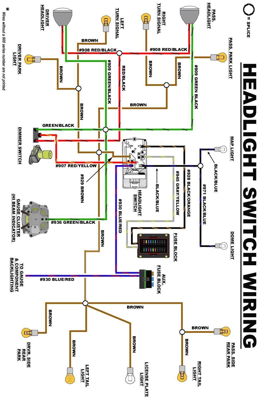
79 79
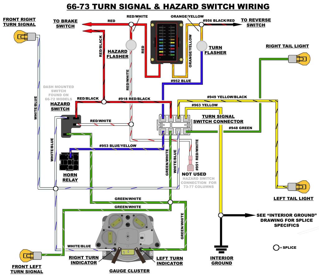
80 80
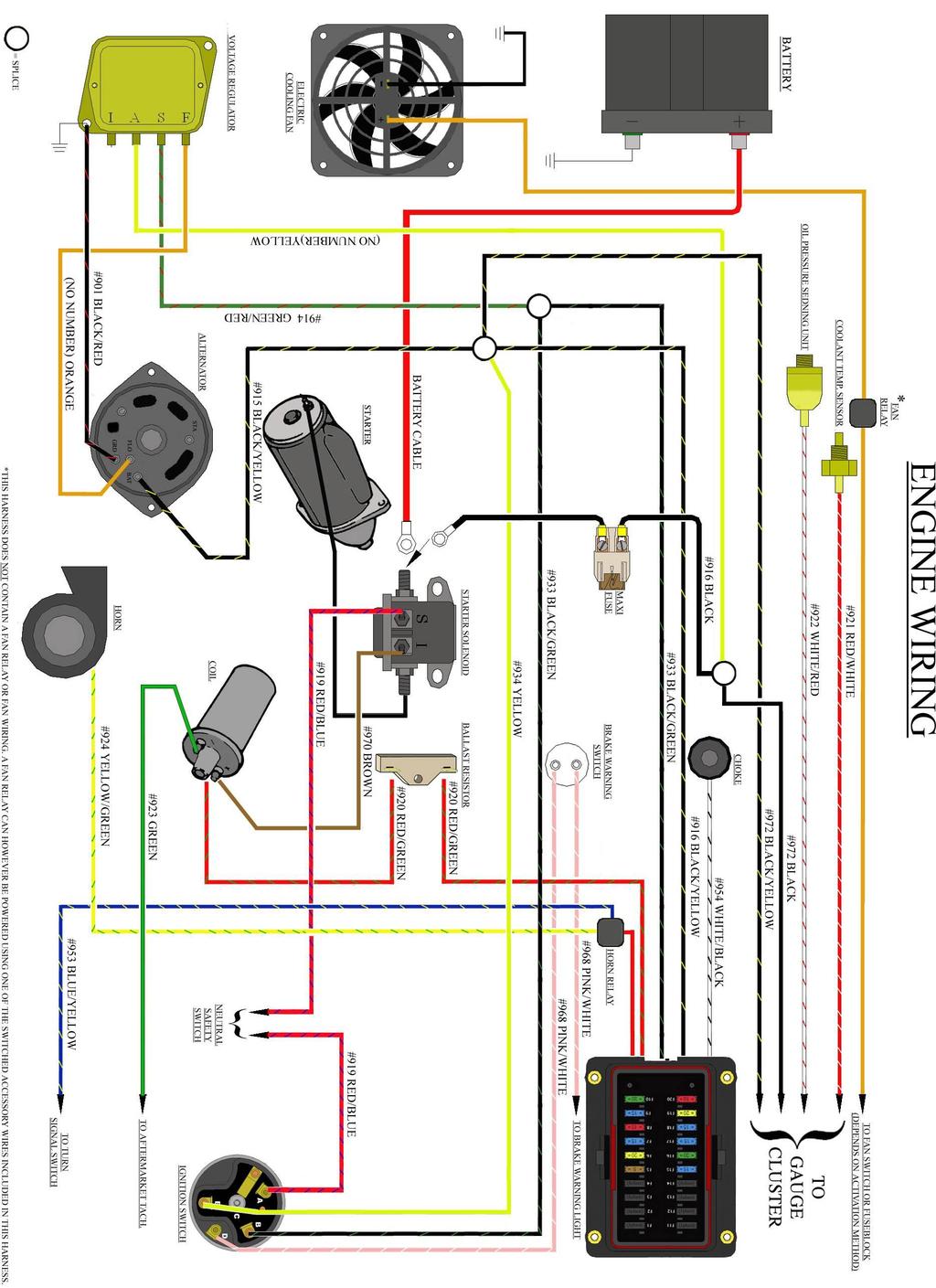
81 81

82 FUSE BLOCK TEMPLATE FUSE BLOCK TEMPLATE Pictured above is a template of the main fuse block. Some distortion to the template image may take place due to the mass printing of this manual; these distortions will be less that 1/16 of an inch. Slight trimming may be needed once all holes, indicated by the shaded areas, have been cut because of this distortion. To avoid possible trimming, screw hole sizes could be enlarged to ¼ and cuts could be made 1/16 outside of the shaded area. Painless Performance Limited Warranty and Return Policy Chassis harnesses, fuel injection harnesses and Striker ColdShot are covered under a lifetime warranty. All other products manufactured and/or sold by Painless Performance are warranted to the original purchaser to be free from defects in material and workmanship under normal use. Painless Performance will repair or replace defective products without charge during the first 12 months from the purchase date. No products will be considered for warranty without a copy of the purchase receipt showing the sellers name, address and date of purchase. You must return the product to the dealer you purchased it from to initiate warranty procedures. 82
Wire Harness Installation Instructions
 Wire Harness Installation Instructions For Installing: Part #50001 Race Car Kit/8 Circuit Part #50201 8 Switch Dash Mounted Panel Part #50202 8 Switch Roll Bar Mounted Panel Manual #90502 Painless Performance
Track Rocker Installation Instructions
 Track Rocker Installation Instructions For Installing Painless Part Numbers: 58103: 8-Switch Customizable Track Rocker Switch Panel w/ Flanged Mount 58106: 6-Switch Customizable Track Rocker Switch Panel
Trail Rocker Installation Instructions
 Trail Rocker Installation Instructions Manual #90580 For Installing Painless Part Numbers: 57000 and 57001 Painless Performance Products recommends you, the installer, read this installation manual from
Trail Rocker Installation
 Trail Rocker Installation Instructions 4, 6, or 8 - Switch Customizable Trail Rocker Switch Panel w/ Flanged Mount For Installing Painless Part Number: 57103, 57106, & 57109 Manual #90636 Painless Performance
Trail Rocker Installation Instructions
 Trail Rocker Installation Instructions Manual #90581 For Installing Painless Part Numbers: 57002 Painless Performance Products recommends you, the installer, read this installation manual from front to
Trail Rocker Installation
 Trail Rocker Installation Instructions Customizable Trail Rocker Control System For Installing Painless Part Number: 57100 Manual #90616 Painless Performance Products recommends you, the installer, read
Track Rocker Installation Instructions
 Track Rocker Installation Instructions Customizable Track Rocker Control System For Installing Painless Part Number: 58100 Track Rocker Relay Center Manual #90641 Painless Performance Products recommends
jegs.com
 Contents Wiring Harness w/ Fuse Panel Installation Instructions Turn Signal Plug w/ Terminals 2 Headlight Plugs 3/4 Grommet 10 ¼ Terminals 4 Ring Terminals 10 Wire Ties Fusible Link 2 Screws & Nuts 2 Plastic
Installation Instructions. Part #65100
 Installation Instructions Part #65100 Perfect Performance Products, LLC Painless Performance Products Division 2501 Ludelle Street Fort Worth, TX 76105-1036 800-423-9696 phone 817-244-4024 fax Web Site:
Off-Road Switch Panel Installation Instructions
 Off-Road Switch Panel Installation Instructions 50330: Off-road 4 Toggle switches/dash Mount w/keyed Ignition Switch 50332: Off-road 6 Toggle switches/dash Mount w/keyed Ignition Switch Painless Performance
Wire Harness Installation Instructions Manual #90576 For Installing:
 Wire Harness Installation Instructions Manual #90576 For Installing: #20112 Direct Fit Camaro Harness 1970-73 #20113 Direct Fit Camaro Harness 1974-77 #20114 Direct Fit Camaro Harness 1978-81 All 26 Circuit
Installation Instructions
 Installation Instructions Part #40120 Perfect Performance Products, LLC Painless Performance Products Division 2501 Ludelle Street Fort Worth, TX 76105-1036 800-423-9696 phone 817-244-4024 fax Web Site:
Trail Rocker Installation Instructions
 Trail Rocker Installation Instructions Trail Rocker - Genesis Bracket For Installing Painless Part Number: 57200 Manual # 90591 To be used with Painless Kit # s: 57000-57005 Painless Performance Products
Wire Harness Installation Instructions
 Wire Harness Installation Instructions For Installing: #20121 Direct Fit Mustang Chassis Harness 1967-1968 22 Circuit Manual #90556 Perfect Performance Products, LLC Painless Performance Products Division
Wire Harness Installation Instructions
 Wire Harness Installation Instructions For Installing: Part #20120 22 Ford Mustang (1965-1966) Manual #90526 Perfect Performance Products, LLC Painless Performance Products Division 2501 Ludelle Street
WIRE HARNESS INSTALLATION INSTRUCTIONS
 WIRE HARNESS INSTALLATION INSTRUCTIONS For Installing: #10206 Classic Plus Customizable GM Pickup Chassis Harness 1967-72 28 Circuit Manual #90510 PERFECT PERFORMANCE PRODUCTS, LLC Painless Performance
Wire Harness Installation Instructions Manual #90571 PART 1 For Installing: #10309 Basic Customizable Nostalgia All Black Chassis Harness 17 Circuit
 Wire Harness Installation Instructions Manual #90571 PART 1 For Installing: #10309 Basic Customizable Nostalgia All Black Chassis Harness 17 Circuit Painless Performance Products recommends you, the installer,
Installation Instructions. Manual # For Installing: Part # Painless Gauge Controller
 Installation Instructions Manual #90579 For Installing: Part #60650- Painless Gauge Controller Perfect Performance Products, LLC Painless Performance Products Division 2501 Ludelle Street Fort Worth, TX
PIN BULKHEAD CONNECTOR KIT
 2501 Ludelle Street Fort Worth, Texas 76105 817-244-6212 Phone 817-244-4024 Fax 888-350-6588 Sales 800-423-9696 Tech E-mail: painless@painlessperformance.com Web: www.painlessperformance.com 40130 22 PIN
INSTRUCTIONS. 20 Circuit Wiring Kit Instructions October 2009, Speedway Motors, Inc.
 1 MAIN FUSE PANEL The main fuse panel harness s designed to be mounted under the dash a the firewall in an area close to the steering column. The enclosed representation of the main dash harness shows
Wire Harness Installation Instructions
 Wire Harness Installation Instructions For Installing: Part #20120 14 Circuit Ford Mustang (1965-1966) Manual #90526 Perfect Performance Products, LLC Painless Performance Products Division 2501 Ludelle
Wire Harness Installation Instructions
 Wire Harness Installation Instructions For Installing: Part #20122 14 Circuit 1969 1970 Ford Mustang Manual #90557 Perfect Performance Products, LLC Painless Performance Products Division 2501 Ludelle
Wire Harness Installation Instructions For Installing:
 Wire Harness Installation Instructions For Installing: #10117 Direct Fit 1967-77 F-Series Ford Truck Harness w/o es 21 Circuit or #10118 Direct Fit 1967-77 F-Series Ford Truck Harness w/ es 21 Circuit
Wire Harness Installation Instructions
 Wire Harness Installation Instructions For Installing: #10127 Customizable Mopar Chassis Harness 21 Circuit Manual #90542 Painless Performance Products, LLC 2501 Ludelle Street Fort Worth, TX 76105-1036
Wire Harness Installation Instructions
 Wire Harness Installation Instructions FOR INSTALLING: PART #10108 20 CIRCUIT BRONCO HARNESS Manual #90521 Painless Performance Products Division Perfect Performance Products, LLC 2501 Ludelle Street,
Installation Instructions For 50330, 50331, 50332, and Off Road Switch Panels
 Installation Instructions For 50330, 50331, 50332, and 50333 Off Road Switch Panels 2501 Ludelle Street Fort Worth, Texas 76105 817-244-6212 Phone 817-244-4024 Fax 888-350-6588 Sales 800-423-9696 Tech
For Installing Harness Number: Manual #90627
 Wire Harness Installation Instructions For Installing Harness Number: 20205: 27 Circuit 1973-1987 GM Truck Manual #90627 Painless Performance Products recommends you, the installer, read this installation
Wire Harness Installation Instructions
 Wire Harness Installation Instructions For Installing: #10112 Classic Customizable Chevy P/U Harness 19 Circuit Manual #90519 Perfect Performance Products, LLC Painless Performance Products Division 2501
CLASSIC UPDATE WIRING KIT
 by Randy Irwin 1955-57 CLASSIC UPDATE WIRING KIT Randy Irwin - Technical Writer Randy has been involved in the Chevy parts business for over 25 years. He is a wizard at creating, making and modifying custom
WIRE HARNESS INSTALLATION INSTRUCTIONS
 WIRE HARNESS INSTALLATION INSTRUCTIONS For Installing: #10205 Classic Plus Customizable GM Pickup Chassis Harness 1973-87 27 Circuit Manual #90507 Painless Performance Products, LLC 2501 Ludelle Street
Classic Update Series
 Classic Update Series 0-4 Ford Falcon and 0- Mercury Comet end view of terminal START HERE! PLEASE READ THIS EFORE STARTING INSTALLATION! This wiring kit is designed for ease of installation. Please read
Classic Update Series
 Classic Update Series 62-65 Ford Fairlane and 62-63 Mercury Meteor end view of terminal START HERE! PLEASE READ THIS EFORE STARTING INSTALLATION! This wiring kit is designed for ease of installation. Please
40A A 40B. Horn Relay Connector. Brake Switch. Third Brake Light. Brake Switch. Brake Switch. Wires. page 3. Rear Body Feed Wires.
 Fuse Box Connections (viewed from underside) 4D 4C 4D 0 50 300 4C 43 7 39 3 6 4 93 A 2G 2F 2E 2D 2C 2B 2G 2F 2E 40 69A 2 1 5 27 69A 3A B 40A,B 11A,B 40A 156 Dimmer Dome Feed page 2 Horn Relay 2D 2 29 40B
Wire Harness Installation Instructions For Installing: #20102 Classic Plus Customizable GM Muscle Car Chassis Harness 25 Circuit
 Wire Harness Installation Instructions For Installing: #20102 Classic Plus Customizable 1969-74 GM Muscle Car Chassis Harness 25 Circuit Manual #90552 Painless Performance Products Division Perfect Performance
INSTRUCTIONS Circuit Wiring Kit Instructions _2017. Fuse Box Connections. (viewed from underside) 2018, Speedway Motors, Inc.
 2018, Speedway Motors, Inc.") Fuse Box Connections (viewed from underside) 4D 4C 100 50 300 4D 4C 4B 4A 43 107 39 103 3B 2G 104 93 2F 2E 2D 2C 2B 40 69A 102 101 105 2G 2F 2E 3A A 2A B 40A,B 27 69A 106 201, Speedway Motors, Inc. 1 Fuse
Fuse Box Connections (viewed from underside) 4D 4C 100 50 300 4D 4C 4B 4A 43 107 39 103 3B 2G 104 93 2F 2E 2D 2C 2B 40 69A 102 101 105 2G 2F 2E 3A A 2A B 40A,B 27 69A 106 201, Speedway Motors, Inc. 1 Fuse
Turn Signal / Horn Kit PN 7101 by All years Polaris RZR 1000 and RZR 900, 900-4, 900 trail, 900S and 900XC STOP - THIS KIT IS DESIGNED
 All years Polaris RZR 1000 and 1000-4 2015 RZR 900, 900-4, 900 trail, 900S and 900XC STOP - THIS KIT IS DESIGNED SPECIFICALLY FOR ALL YEAR AND MODEL POLARIS RZR 1000 AND 1000-4. ALSO THE 2015 POLARIS RZR
accessory connection rear body connection 40G 17A instrument cluster and map lamp ground 150A,B 15A 14A Circuit Branch 500A fog lamp switch
 accessory rear body 19 9 11 instrument cluster and map 10A, 0 4 3 7 40G 18 30 17A 24 1A 14A 9 8A instrument cluster 4E 31 3 121 11 33 401 10A 39A 400 30 washer and wiper switch 93A, 94 93 glovebox, map
Wire Harness Installation Instructions For Installing:
 Wire Harness Installation Instructions For Installing: #20106 Classic Plus Customizable Tri-Five Chevy Harness 28 Circuit #20107 Classic Customizable Tri-Five Chevy Harness 21 Circuit Manual #90553 Painless
Mustang Classic Update Series Kit
 accessory rear body 19 9 11 instrument cluster and map 10A, 0 4 3 7 40G 18 30 17A 24 1A 14A 9C 8A instrument cluster 4E 31 3 121 11 401 10A 3 400 30 washer and wiper switch 93A, 93 glovebox, map light,
Installation Tips for your Remote Start/Keyless Entry (for Ford Vehicles) v3.3 Updated 1/13/2013
 v3.3 Updated 1/13/2013") Installation Tips for your Remote Start/Keyless Entry (for Ford Vehicles) v3.3 Updated 1/13/2013 Thank you for purchasing your remote start from MyPushcart.com - an industry leader in providing remote
Installation Tips for your Remote Start/Keyless Entry (for Ford Vehicles) v3.3 Updated 1/13/2013 Thank you for purchasing your remote start from MyPushcart.com - an industry leader in providing remote
Manual P/N Copyright Third Edition June 21, 2005
 P/N 60212, 60213, 60214 & 60215 1996-99 GM VORTEC WIRE HARNESS INSTALLATION INSTRUCTIONS Manual P/N 90524 Copyright 2003 Third Edition June 21, 2005 PAINLESS PERFORMANCE PRODUCTS 2501 Ludelle Street, Fort
Installation Tips for RS1 + EVO-RIDE + SPDT. *(reglar key, automatic transmission vehicles ONLY)*
*") Installation Tips for RS1 + EVO-RIDE + SPDT TIP SHEET T1235 *(reglar key, automatic transmission vehicles ONLY)* Thank you for purchasing your remote start from MyPushcart.com - an industry leader in providing
Installation Tips for RS1 + EVO-RIDE + SPDT TIP SHEET T1235 *(reglar key, automatic transmission vehicles ONLY)* Thank you for purchasing your remote start from MyPushcart.com - an industry leader in providing
Installation Tips for your Crimestopper/ProStart Remote Start system (add-on for GM vehicles) v1.02 updated 1/16/2013
 v1.02 updated 1/16/2013") Installation Tips for your Crimestopper/ProStart Remote Start system (add-on for GM vehicles) v1.02 updated 1/16/2013 Thank you for purchasing your remote start from MyPushcart.com - an industry leader
Installation Tips for your Crimestopper/ProStart Remote Start system (add-on for GM vehicles) v1.02 updated 1/16/2013 Thank you for purchasing your remote start from MyPushcart.com - an industry leader
Installation Tips for your Remote Start/Keyless Entry (for Honda/Acura Vehicles) [EVO-ALL] v1.02 updated 9/13/2013
![Installation Tips for your Remote Start/Keyless Entry (for Honda/Acura Vehicles) [EVO-ALL] v1.02 updated 9/13/2013](/thumbs/87/96035180.jpg "Installation Tips for your Remote Start/Keyless Entry (for Honda/Acura Vehicles) [EVO-ALL] v1.02 updated 9/13/2013") Installation Tips for your Remote Start/Keyless Entry (for Honda/Acura Vehicles) [EVO-ALL] v1.02 updated 9/13/2013 Thank you for purchasing your remote start from MyPushcart.com - an industry leader in
Installation Tips for your Remote Start/Keyless Entry (for Honda/Acura Vehicles) [EVO-ALL] v1.02 updated 9/13/2013 Thank you for purchasing your remote start from MyPushcart.com - an industry leader in
72 Mustang Mach 1 tachometer cluster and gauge conversion
 72 Mustang Mach 1 tachometer cluster and gauge conversion Dated: 02-17-2009 (drafted by a Chevy person working on his first Ford -not good-) Revised: 11-05-2010 The following information pertains to how
Ford Mustang V6 OEM-Style Fog Light Kit Parts List: Quantity: Tool List:
 2015-2017 Ford Mustang V6 OEM-Style Fog Light Kit Parts List: Quantity: Tool List: LED Foglights/ Bezels 2 Flat head & Phillips screwdriver (if you ordered part#3600) Ratchet & Socket set OR Wiring harness
Owner s Manual Electronic Harness Controller P/N ASM4250
 Owner s Manual Electronic Harness Controller P/N ASM4250 Thunder Heart Performance Corporation MANUAL P/N EI4250 120 Industrial Drive Revision 6/3/04 White House, TN 37188 www.thunder-heart.com TABLE
PN R CHEVY CAMARO w/reverse Two panel Sequential LED Taillight kit installation guide. Kit Contents:
 Two panel Sequential LED Taillight kit installation guide Kit Contents: 2 LED panels 4 rubber grommets 1 power wire with t-tap 1 driver side LED harness, 24 1 passenger side LED harness, 48 2 LED extension
Installation Instructions For #64320 Striker Turbo Timer Module
 2501 Ludelle Street Fort Worth, Texas 76105 817-244-6212 Phone 817-244-4024 Fax 888-350-6588 Sales 800-423-9696 Tech E-mail: painless@painlessperformance.com Web: www.painlessperformance.com Installation
Classic Update Series
 Classic Update Series 1964-1966 Ford Mustang START HERE! PLEASE READ THIS EFORE STARTING INSTALLATION! This wiring kit is designed for ease of installation. Please read the guidelines below, EFORE STARTING
Wire Harness Installation Instructions
 Wire Harness Installation Instructions For Installing: Part #10143 Landcruiser / Scout Weatherproof Harness Manual #90548 Painless Performance Products Division Perfect Performance Products, LLC 2501 Ludelle
Installation Tips for your Crimestopper/ProStart Remote Start system (for GM vehicles) v1.01 updated 2/27/2012
 v1.01 updated 2/27/2012") Installation Tips for your Crimestopper/ProStart Remote Start system (for GM vehicles) v1.01 updated 2/27/2012 Thank you for purchasing your remote start from MyPushcart.com - an industry leader in providing
Installation Tips for your Crimestopper/ProStart Remote Start system (for GM vehicles) v1.01 updated 2/27/2012 Thank you for purchasing your remote start from MyPushcart.com - an industry leader in providing
Installation Tips for your Remote Start system (for RS4LX>GMBP for GM vehicles)
") Installation Tips for your Remote Start system (for RS4LX>GMBP for GM vehicles) Thank you for purchasing your remote start from MyPushcart.com - an industry leader in providing remote starts to doit-yourself
Installation Tips for your Remote Start system (for RS4LX>GMBP for GM vehicles) Thank you for purchasing your remote start from MyPushcart.com - an industry leader in providing remote starts to doit-yourself
Installation Tips for your Excalibur Remote Start (for Honda and Acura Vehicles) rev 11/28/2012
 rev 11/28/2012") Installation Tips for your Excalibur Remote Start (for Honda and Acura Vehicles) rev 11/28/2012 Thank you for purchasing your remote start from MyPushcart.com - an industry leader in providing remote starts
Installation Tips for your Excalibur Remote Start (for Honda and Acura Vehicles) rev 11/28/2012 Thank you for purchasing your remote start from MyPushcart.com - an industry leader in providing remote starts
2016 HONDA 1000 Pioneer PN 3102 Turn signal / horn kit rev nc
 2016 Honda 1000 Pioneer STOP - THIS KIT IS DESIGNED SPECIFICALLY FOR 2016 HONDA 1000 PIONEER IF YOUR MACHINE IS NOT THIS MODEL DO NOT PROCEED. THIS KIT DOES NOT WORK ON THE PIONEER 500 nor 700 S. Contact
Step 1 Wiring your remote start. Installation Tips for your Remote Start system (for GM vehicles) V3.3 revised 9/12/2013
 V3.3 revised 9/12/2013") Installation Tips for your Remote Start system (for GM vehicles) V3.3 revised 9/12/2013 Thank you for purchasing your remote start from MyPushcart.com - an industry leader in providing remote starts to
Installation Tips for your Remote Start system (for GM vehicles) V3.3 revised 9/12/2013 Thank you for purchasing your remote start from MyPushcart.com - an industry leader in providing remote starts to
Installation Tips Crimestopper/ProStart Remote Start system + PLJX + DLRM + SPDT (for GM vehicles) T0760 v1.1 updated 2/5/14
 T0760 v1.1 updated 2/5/14") Installation Tips Crimestopper/ProStart Remote Start system + PLJX + DLRM + SPDT (for GM vehicles) T0760 v1.1 updated 2/5/14 Thank you for purchasing your remote start from MyPushcart.com - an industry
Installation Tips Crimestopper/ProStart Remote Start system + PLJX + DLRM + SPDT (for GM vehicles) T0760 v1.1 updated 2/5/14 Thank you for purchasing your remote start from MyPushcart.com - an industry
Installation Tips for your Remote Start/Keyless Entry (for Mazda Vehicles) v3.1 Updated 9/22/2012
 v3.1 Updated 9/22/2012") Installation Tips for your Remote Start/Keyless Entry (for Mazda Vehicles) v3.1 Updated 9/22/2012 Thank you for purchasing your remote start from MyPushcart.com - an industry leader in providing remote
Installation Tips for your Remote Start/Keyless Entry (for Mazda Vehicles) v3.1 Updated 9/22/2012 Thank you for purchasing your remote start from MyPushcart.com - an industry leader in providing remote
Part # GM LS2, 3 & 7-95mm Throttle Body
 Part # 65303 2006-2011 GM LS2, 3 & 7-95mm Throttle Body Perfect Performance Products, LLC 2501 Ludelle St. Fort Worth, Texas 76105 (800) 423-9696 1 We are always concerned about any corrections or improvements
Wire Harness Installation Instructions
 Wire Harness Installation Instructions For Installing: #10140 Customizable Weatherproof Chassis Harness 26 Circuit Manual #90531 Painless Performance Products, LLC 2501 Ludelle Street Fort Worth, TX 76105-1036
Classic Update Series
 Classic Update Series 67-72 Ford Truck START HERE! PLEASE READ THIS EFORE STARTING INSTALLATION! This wiring kit is designed for ease of installation. Please read the guidelines below, EFORE STARTING your
1962 Wiring Diagram. The Basics Part One. by Bob Mannel
 The Basics Part One 1962 Wiring Diagram by Bob Mannel Most restorers fear the wiring probably since it seems to be the most abused system in our Fairlanes. With cuts, splices, and extra wires running hither
TIP SHEET T0491. Installation Tips for your Excalibur RS Passlock-sl2(4) + DLRC + SPDT
 + DLRC + SPDT") TIP SHEET T0491 Installation Tips for your Excalibur RS-360 + Passlock-sl2(4) + DLRC + SPDT For Chevrolet: Astro 1998-2005, Avalanche 2002, Blazer 1998-2005, Cavalier 2000-2003, Express Van 1998-2005,
TIP SHEET T0491 Installation Tips for your Excalibur RS-360 + Passlock-sl2(4) + DLRC + SPDT For Chevrolet: Astro 1998-2005, Avalanche 2002, Blazer 1998-2005, Cavalier 2000-2003, Express Van 1998-2005,
WIRE HARNESS INSTALLATION INSTRUCTIONS. For Installing: Part # Circuit Universal CJ Jeep Harness ( ) Manual #90513
 Manual #90513") WIRE HARNESS INSTALLATION INSTRUCTIONS For Installing: Part #10110 12 Circuit Universal CJ Jeep Harness (1975-86) Manual #90513 Perfect Performance Products, LLC Painless Performance Division 2501 Ludelle
WIRE HARNESS INSTALLATION INSTRUCTIONS For Installing: Part #10110 12 Circuit Universal CJ Jeep Harness (1975-86) Manual #90513 Perfect Performance Products, LLC Painless Performance Division 2501 Ludelle
Installation Tips for your Remote Start system (for Toyota Camry & Prius C, ) Crimestopper RS0+ EVO-ALL T3468 rev#1.
 Crimestopper RS0+ EVO-ALL T3468 rev#1.") Installation Tips for your Remote Start system (for Toyota Camry & Prius C, 2012-2014) Crimestopper RS0+ EVO-ALL T3468 rev#1.1 1/22/2015 Thank you for purchasing your remote start from MyPushcart.com -
Installation Tips for your Remote Start system (for Toyota Camry & Prius C, 2012-2014) Crimestopper RS0+ EVO-ALL T3468 rev#1.1 1/22/2015 Thank you for purchasing your remote start from MyPushcart.com -
RS4-7/PS4-7 + (2) + SPDT T3015, T3053
 + SPDT T3015, T3053") TIP SHEET Installation Tips for your RS4-7/PS4-7 + Honda-SL3 (2) + SPDT T3015, T3053 v1.3 4/25/14 Honda: ( 98-02 Accord), ( 98-01 CRV), ( 98-04 Odyssey), ( 03-04 Pilot) Acura: ( 98-99 EL), ( 98-03 CL),
TIP SHEET Installation Tips for your RS4-7/PS4-7 + Honda-SL3 (2) + SPDT T3015, T3053 v1.3 4/25/14 Honda: ( 98-02 Accord), ( 98-01 CRV), ( 98-04 Odyssey), ( 03-04 Pilot) Acura: ( 98-99 EL), ( 98-03 CL),
Remote Start Kit for GM Installation RS1/3/4/7 + ADS-DL Tip Sheet
 Remote Start Kit for GM Installation RS1/3/4/7 + ADS-DL Tip Sheet rev 1.4 12/16/2013 Thank you for purchasing your remote start from MyPushcart.com - an industry leader in providing remote starts to do-it-yourself
Installation Instructions for the Plug & Play Remote Start Package (EVOCHR4)
") T6002 v1.1 02/2013 Installation Instructions for the Plug & Play Remote Start Package (EVOCHR4) For CHRYSLER Town & Country 2008-2012 Review the remote start installation manual for safety instructions!
T6002 v1.1 02/2013 Installation Instructions for the Plug & Play Remote Start Package (EVOCHR4) For CHRYSLER Town & Country 2008-2012 Review the remote start installation manual for safety instructions!
20 CIRCUIT ATO FUSE CENTER INSTALLATION INSTRUCTIONS
 2501 Ludelle Street Fort Worth, Texas 76105 817-244-6212 phone 817-244-4024 fax 800-423-9696 Tech E-Mail: painless@painlessperformance.com Web: www.painlessperformance.com 30003 20 CIRCUIT ATO FUSE CENTER
Installation Instructions
 Installation Instructions Jeep JK Unlimited (2007 Present) Mounting Bracket and Air Line System Kit for ARB On-Board Twin Air Compressor (CKMTA12) Made in the USA Kit Contents: 1 Bracket for ARB Compressor
Installation Instructions for the Plug & Play Chrysler/Dodge/Jeep Remote Start Package w/mux T5
 v1.01 12/14/2102 Installation Instructions for the Plug & Play Chrysler/Dodge/Jeep Remote Start Package w/mux T5 Review the remote start installation manual for safety instructions! Overview Your kit consists
Installation Tips for your Add-on Remote Start (for GM vehicles with INTSL Install 2) v3.2 Updated 11/12/2012
 v3.2 Updated 11/12/2012") Installation Tips for your Add-on Remote Start (for GM vehicles with INTSL Install 2) v3.2 Updated 11/12/2012 Thank you for purchasing your remote start from MyPushcart.com - an industry leader in providing
Installation Tips for your Add-on Remote Start (for GM vehicles with INTSL Install 2) v3.2 Updated 11/12/2012 Thank you for purchasing your remote start from MyPushcart.com - an industry leader in providing
Wire Harness Installation Instructions
 Wire Harness Installation Instructions For Installing: #10123 Customizable Ford Color Coded Harness 21 Circuit Manual #90545 Painless Performance Products, LLC 2501 Ludelle Street Fort Worth, TX 76105-1036
Wire Harness Installation Instructions For Installing:
 Wire Harness Installation Instructions For Installing: #10120 Classic Customizable Trunk Mount Harness 21 Circuit #10220 Classic Plus Customizable Trunk Mount Harness 28 Circuit Painless Performance Products,
INSTALLATION GUIDE OWNER S GUIDE
 INSTALLATION GUIDE OWNER S GUIDE REMOTE STARTER MODEL RS82 CONTENTS System Features... 1 System Components... 1 Required Tools... 1 Technical Assistance... 1 Before You Begin... 1-2 Precautions... 2 Making
TIP SHEET T2352, T3396. Installation Tips for RS1 + EVO-ALL 1-BUTTON REMOTE STARTER FOR: Acura RDX PUSH-TO-START / AUTOMATIC
 Installation Tips for RS1 + EVO-ALL 1-BUTTON REMOTE STARTER FOR: Acura RDX 2013-2015 PUSH-TO-START / AUTOMATIC TIP SHEET T2352, T3396 Thank you for purchasing your remote start from MyPushcart.com - an
30140 F5 Dual Fan Controller
 30140 F5 Dual Fan Controller 1 2501 Ludelle Street Fort Worth, Texas 76105 817-244-6212 Phone 817-244-4024 Fax 888-350-6588 Sales 800-423-9696 Tech E-mail: painless@painlessperformance.com Web: www.painlessperformance.com
P/N & GM LS1 w/mechanical (cable) THROTTLE BODY FUEL INJECTION WIRE HARNESS INSTALLATION INSTRUCTIONS
 THROTTLE BODY FUEL INJECTION WIRE HARNESS INSTALLATION INSTRUCTIONS") P/N 60508 & 60509 1997-0 GM LS1 w/mechanical (cable) THROTTLE BODY FUEL INJECTION WIRE HARNESS INSTALLATION INSTRUCTIONS Manual P/N 9050 Painless Performance Products, LLC 501 Ludelle Street Fort Worth,
P/N 60508 & 60509 1997-0 GM LS1 w/mechanical (cable) THROTTLE BODY FUEL INJECTION WIRE HARNESS INSTALLATION INSTRUCTIONS Manual P/N 9050 Painless Performance Products, LLC 501 Ludelle Street Fort Worth,
Wire Harness Installation Manual # Part # 60617
 Wire Harness Installation Manual #90572 For Installing: Part # 60617 26 Circuit/7 Relay 4.8L-6.0 L w/4l60e Integrated Harnesses Perfect Performance Products, LLC Painless Performance Products Division
29048, 29049, 29050, 29051, 29052, 29053, 29054,
 April 15, 2014 Lit. No. 29225, Rev. 11 29048, 29049, 29050, 29051, 29052, 29053, 29054, 29400 5 HARNESS KIT 3 PORT ISOLATION MODULE LIGHT SYSTEM w/2 PLUG SYSTEM HARNESSES Installation Instructions Read
DirectMount EXHAUST BRAKES
 DirectMount EXHAUST BRAKES APPLICATION: Fixed Orifice and PRXB Exhaust Brakes 2003 2005 Dodge Trucks with 3.5" & 4" Exhaust and 47RE & 48RE Automatic Transmissions Only Vehicles with an existing air compressor
Small knife. Remove black panel shown. Save 6 retaining pins for re-install later.
 2005-2009 Ford Mustang V6 Fog Light Wiring Kit Parts List: Quantity: Tools Required: Wiring harness 1 Flat head screwdriver PB-3425 Parts Bag 1 Ratchet & Socket set OR Ford OEM Switch (if you 1 Adjustable
Installation Tips for your GMDLBP + Excalibur Remote Start system (for GM vehicles) v1.01 updated 10/09/13
 v1.01 updated 10/09/13") Installation Tips for your GMDLBP + Excalibur Remote Start system (for GM vehicles) v1.01 updated 10/09/13 Thank you for purchasing your remote start from MyPushcart.com - an industry leader in providing
Installation Tips for your GMDLBP + Excalibur Remote Start system (for GM vehicles) v1.01 updated 10/09/13 Thank you for purchasing your remote start from MyPushcart.com - an industry leader in providing
DASH/MAIN HARNESS. NOTE: wires 400 & 401, must be twisted together.
 Electric Speedo Ground 151 Turn Flasher 16A 4 150 8A, Cluster Connections 31 33 30 35 151 (electric speedo) 402 401 NOTE: wires 400 & 401, must be twisted together. 156D, E Panel Dimmer 8A 9, C 2D Headlight
INSTRUCTIONS 12 Circuit Wiring Kit Instructions
 Fan 47 9 56 4 7 6 72 40 45 48 5 8 6 Gauge Power Temp Sender Headlight Power Power Radio Constant Power Instruments and Dash Rear of Vehicle Ignition and Lights Fuse Panel & Front of Vehicle Horn Alt Excitor
29048, 29049, 29050, 29051, 29052, 29053, 29054,
 May 1, 2018 Lit. No. 29206, Rev. 13 29048, 29049, 29050, 29051, 29052, 29053, 29054, 29400 7 HARNESS KIT 3 PORT ISOLATION MODULE LIGHT SYSTEM w/3 PLUG SYSTEM HARNESSES Installation Instructions Read this
Installation Tips for your RS-1 + Honda-SL3 (1.b) Remote starter Honda: ( FIT), ( Pilot), ( Ridgeline) Acura: ( MDX)
 Remote starter Honda: ( FIT), ( Pilot), ( Ridgeline) Acura: ( MDX)") Installation Tips for your RS-1 + Honda-SL3 (1.b) Remote starter Honda: ( 06-08 FIT), ( 05-08 Pilot), ( 06-13 Ridgeline) Acura: ( 03-06 MDX) TIP SHEET T0777 Thank you for purchasing your remote start from
Installation Tips for your RS-1 + Honda-SL3 (1.b) Remote starter Honda: ( 06-08 FIT), ( 05-08 Pilot), ( 06-13 Ridgeline) Acura: ( 03-06 MDX) TIP SHEET T0777 Thank you for purchasing your remote start from
30107 & PACK & 6-PACK RELAY BANK
 30107 & 30108 2501 Ludelle Street Fort Worth, Texas 76105 817-244-6212 Phone 817-244-4024 Fax 888-350-6588 Sales 800-423-9696 Tech E-mail: painless@painlessperformance.com Web: www.painlessperformance.com
Remove 4 circled pins. Route wiring along dashed line. Remove the 2 9mm nuts and black retaining plate that secure extractor.
 2015 Ford Mustang Turn Signal Hood Kit Parts List: Quantity: Tool List: Bracket & pre-installed lamp 2 Flat head screwdriver Wiring harness 1 Phillips screwdriver PB-3660 Parts Bag 1 Ratchet & Socket set
Installation Instructions - ECS Tuning Vent Pod Vacuum/Boost Gauge Kit
 Installation Instructions - ECS Tuning Vent Pod Vacuum/Boost Gauge Kit This tutorial is provided as a courtesy by ECS Tuning. Part Number for (2005-2008) Proper service and repair procedures are vital
Rear Body 40D 156A 24 17A 151 3D. 8A,8B,8C under hood light. Horn Relay 91
 fuse box as viewed from the wire entry side Mating connector is plugged into Power Accessory connector 40D Rear Body 19 18 9B 30 LH Courtesy Light 40A,D 4D, 43 156B,C 16 16A 4C 3D 3C 16A 3G 4B 3G 116 4A&130
29048, 29049, 29050, 29051, 29052, 29053, 29054,
 April 15, 2014 Lit. No. 29206, Rev. 11 29048, 29049, 29050, 29051, 29052, 29053, 29054, 29400 5 HARNESS KIT 3 PORT ISOLATION MODULE LIGHT SYSTEM w/3 PLUG SYSTEM HARNESSES Installation Instructions Read
WIRE HARNESS INSTALLATION INSTRUCTIONS
 WIRE HARNESS INSTALLATION INSTRUCTIONS For Installing: 22 Circuit Chassis Harness Kits #10105 Classic Customizable Jeep CJ ( 74-back) #10106 Classic Customizable Jeep CJ (75-later) Manual #90504 Painless
Instruction Part #90577
 Phantom Key Push Button Ignition System Instruction Part #90577 For Installing: Part # s 55000, 55001, 55002, 55003, 55004, & 55005 Perfect Performance Products, LLC Painless Performance Products Division
*(reglar key vehicles ONLY)* Read the entire installation manual. There are several safety tips in there to know before you start
* Read the entire installation manual. There are several safety tips in there to know before you start") Installation Tips for RS4 + EVO-RIDE + SPDT TIP SHEET T2519 2009-2011 Ford Crown Victoria 2009-2012 Ford E-150 2009 Ford E-150 Econoline Club Wagon 2008-2010 Ford E-250 2010 Ford E-250 Econoline 2010 Ford
Installation Tips for RS4 + EVO-RIDE + SPDT TIP SHEET T2519 2009-2011 Ford Crown Victoria 2009-2012 Ford E-150 2009 Ford E-150 Econoline Club Wagon 2008-2010 Ford E-250 2010 Ford E-250 Econoline 2010 Ford
RAINGEAR 1955/ 1956 Chevrolet
 RAINGEAR 1955/ 1956 Chevrolet GETTING STARTED: SOME RECOMMENDATIONS PLEASE TRY OUR WAY FIRST! Note: This system is designed with built in adjustments to fit in your car. If, as you are installing it, you
Installation Instructions Jeep CJ-7
 Retrofit Steering Column Installation Instructions 1976-86 Jeep CJ-7 For Part # s 1520800010, 152800020, 1520800051 www.ididitinc.com 610 S. Maumee St., Tecumseh, MI 49286 (517) 424-0577 (517) 424-7293
TIP SHEET. Installation Tips for SP-404/SP EVO-ALL + SPDT Remote Start/Alarm T1642
 TIP SHEET Installation Tips for SP-404/SP-502 + EVO-ALL + SPDT Remote Start/Alarm T1642 Nissan Armada: 2008-2012 Nissan Cube: 2009-2012 Nissan Frontier: 2008-2012 Nissan Pathfinder: 2009-2012 Nissan Quest:
Thank you for purchasing the Craven Speed FlexPod Complete Gauge Pod Kit For R56, R58, R59, R60 with Refresh Engines (2011+)
") Thank you for purchasing the Craven Speed FlexPod Complete Gauge Pod Kit For R56, R58, R59, R60 with Refresh Engines (2011+) Before You Start Please read instructions completely before installing. These
Thank you for purchasing the Craven Speed FlexPod Complete Gauge Pod Kit For R56, R58, R59, R60 with Refresh Engines (2011+) Before You Start Please read instructions completely before installing. These
PRXB EXHAUST BRAKE MAXIMUM EXHAUST FLOW DESIGN
 MAXIMUM EXHAUST FLOW DESIGN PRXB EXHAUST BRAKE C44072/C44073/C44074/C44075/C44076 APPLICATION: 994-2002 DODGE RAM TRUCKS W/5.9L CUMMINS DIESEL ENGINES WITH MANUAL & AUTOMATIC TRANSMISSIONS STOCK DODGE