Woda-Sci System Installation Parts Set
|
|
|
- Merry Lawrence
- 6 years ago
- Views:
Transcription


1 Installation Manual

2 Woda-Sci System Installation Parts Set 5/32 x 3 ½ Drill Bit - 5 Connector Body - 7 3/8 Locking Nut - 8 3/16 x 1 ¼ Concrete Anchors- 4 Mounting Screws - 3 Stainless Steel Hanger - 9 Mounting Brackets Float Stainless Steel Level Sensing Assembly - 6 Stainless Steel Ring Clamp - 10 Pressure Sensor - 1 Band Ties - 11 The installation parts set, included with the Woda-Sci control system, will be referenced in the following instructions to the above numbers. 2
 and a ½ to 1 HP")

3 Wall Plug & Pump Selection 1. For the Woda-Sci Sump Control System, you will need a 115V, 20A NEMA 5-20R wall receptacle located within 6 feet of your sump pit, installed by a qualified electrician (see Figure 1) and a ½ to 1 HP sprinkler pump or shallow well pump if you plan to use the system for irrigation only. If you plan to use the system for manual hose watering, see Appendix A, Example 1, on page 11 for a typical installation application. Appendix A, Example 2, on page 12 shows a typical installation application for use with an automatic sprinkler system. The third example, on Page 13, Appendix A shows a typical installation application for use with an automatic sprinkler system and home water supply usage. Note: Local codes may require a GFCI outlet, like the one shown to the left. Figure 1 Sprinkler Pump or Shallow Well Pump 2. Unpack your selected sprinkler pump or shallow well pump. Most ¾ and 1 HP pumps come factory set for 230V. You will need to change the selection to 115 volts and install a minimum 6 ft. power and ground cable with a 115V, 20A NEMA 5-20R plug to the pump (See Figure 2). Important Ensure that your pump comes with or that you retrofit your pump with a pressure switch that will turn it off in the event of a high pressure situation Figure 2 Important: Sprinkler or Shallow Well Pump output is 115V, 60 Hz, 16A max. or 1 HP max. 3

4 3. You may purchase a kit from Woda-Sci (Pump output kit #WS-010, see Figure 3 below) which will contain the following; 1 stainless steel T stainless steel male nipple 1 stainless steel plug Pump Output Assembly 1/8 x 1.5 threaded stainless steel nipple 1/8 female stainless steel T fitting p.s.i. analog pressure gauge mounting orifice for the pressure sensor If you choose not to purchase the kit you will need to obtain the items listed above from your local hardware or plumbing store. Perform the following installation steps, referring to Figure 3 below. Install the 1 x 1.5 male nipple on one end of the 1 inch female T fitting. On the top of the T fitting, install the 1 in plug with a 1/8 threaded hole in the top. In the threaded hole install the 1/8 x 1.5 threaded nipple. Install the 1/8 female T fitting on the nipple On the horizontal leg of the T-fitting mount a p.s.i. analog pressure gauge On the vertical leg of the T-fitting, mount the Pressure Sensor (1) included with the Woda-Sci system. When complete, install on the outlet of your shallow well or sprinkler pump. Pressure Sensor (1) Analog Pressure Gauge Note: Included as part of Woda-Sci System. This pressure sensor is a secondary high pressure sensor. Your pump should always have a high pressure cut-out switch as shown in Figure 2. 1 plug 1/8 T 1/8 x 1.5 threaded male nipple 1 T 1 x 1.5 male nipple Figure 4 3
 and Mounting Screws (3) and attach to the back side of the controller as shown in Figure 4.")

5 . Remove from box 4. Remove the Woda-Sci controller from the box. Turn the controller over and lay it front side down on a layer of the included bubble wrap packaging material. Find the package of Mounting Brackets (2) and Mounting Screws (3) and attach to the back side of the controller as shown in Figure 4. Mounting Brackets (2) and Mounting Screws (3) X 2 Figure 4 Mount to Wall 5. Next, determine a mounting location for the controller on the basement wall, centered approximately 5 ft. above the concrete basement floor and within 2 feet, in either direction, from the centerline of your sump pit. Mount to the wall utilizing the 4 included 3/16 x 1 ¼ concrete anchors and the 5/32 x 3 ½ drill bit (5) to drill the holes as shown in Figure 5. 3/16 x 1 ¼ Concrete Anchors (4) x 2 Figure 5 5

6 Install Sprinkler/Shallow Well Pump 6. Now, install your sprinkler or shallow well pump into the sump pit following the manufacturer s instructions, with the bottom of the foot valve approximately 1 inch off of the bottom of the sump pit and the outlet assembly from step 3. Plumb the horizontal leg of the 1 T into your home water supply and /or sprinkler system supply line. Connect Pressure Sensor 7. From the Woda-Sci controller, connect the ring terminal with the red wire of the 2 wire pressure sensor input to the G terminal post of the pressure sensor and the ring terminal with the black wire to the WK terminal post of the pressure sensor as shown in Figure 6 below. Figure 6 Unpack Sensor Assembly 8. Gently remove the 4 Float Stainless Steel Level Sensing Assembly (6) from the bubble wrap. Remove the Connector Body (7) in the plastic bag from the stem of the sensor and set aside. Next, remove the rubber band from the electrical cable and uncoil it. 6
 and 3/8 locking nut (8) and gently feed the 5 gold plated terminals, from the bottom, through the hole furthest away from the bend of the hanger and")
7 Connect 5 Gold Plated Terminals 9. Find the stainless steel level sensor hanger (9) and 3/8 locking nut (8) and gently feed the 5 gold plated terminals, from the bottom, through the hole furthest away from the bend of the hanger and then through the underside of the locking nut. Set the assembly down on a hard surface. Install the 5 gold plated terminals in the connector body (7) in the cavities shown in the table in Figure 7. Connector Body (7) Cavity 1 Red Cavity 2 White Cavity 3 Green Cavity 4 Brown Cavity 5 Black Cavity 6 Empty Figure 7 7
 to the hanger by installing and running down the 3/8 locking nut on the top of the level sensor assembly as shown in")
.")
8 Secure the Level Sensor Assembly 10. Next, secure the 4 float stainless steel level sensor assembly (9) to the hanger by installing and running down the 3/8 locking nut on the top of the level sensor assembly as shown in Figure 8. 3/8 Locking Nut (8) Stainless Steel Hanger (9) Figure 8 Install the Level Sensor Assembly 11. Install the level sensor assembly on the intake pipe of the sprinkler or shallow well pump in the sump pit, utilizing the provided stainless steel ring clamp (10). Be sure that the sensor assembly hangs freely in the sump and has a minimum of 1.5 inches of clearance from the sump walls, sump pump, sump pump float or diaphragm switch, sump pump exhaust tube, etc. as shown in Figure 9. Stainless Steel Ring Clamp (10) Figure 8 9

. Use additional band ties to secure the level sensor cable to the pressure sensor cable and to the intake pipe.")
9 Correct Sensor Positioning 12. The stop for the top float sensor should be approximately 4 from the top of the basement floor as shown in Figure 10. Four inches from basement floor to top of sensor Figure 10 Connecting Water Level Sensor to Controller 13. Connect the water level sensor connector to the 6 pin water level sensor connector plug from the Woda-Sci Sump Controller, coil the excess level sensor cable and secure using the provided Band Ties (11). Use additional band ties to secure the level sensor cable to the pressure sensor cable and to the intake pipe. Coiled and band tied excess cable Water level sensor connection Figure 11 9

10 Sprinkler System wiring 14. If you are using the Woda-Sci system for irrigation with an automatic sprinkler system, cut the band tie securing the 8 position terminal strip and mount to a floor joist immediately above the controller using the 2 - #6 x 1 5/8 wood screws included. Connect the household sprinkler stations 1-6 to the corresponding wire colors on the terminal strip as shown in Figure 12. Station 1 Station 2 Station 3 Station 4 Station 5 Station 6 Return Red Blue Green Yellow Orange Brown White Figure 12 Powering Up Your System 15. Plug your sump pump into the receptacle located on the underside of the Woda-Sci controller below the Sump Pump label. Then, plug your sprinkler pump or shallow well pump into the receptacle located on the underside of the Woda-Sci controller below the Home / Irrigation Pump label. Finally, plug the Woda-Sci controller into the wall plug and refer to the Operation Manual to set-up your system to your individual needs. Important: Sump Pump Output is 115 VAC, 60 Hz, 8A max. or ½ HP max. 10


11 Appendix A Installation Application Examples Example 1 11

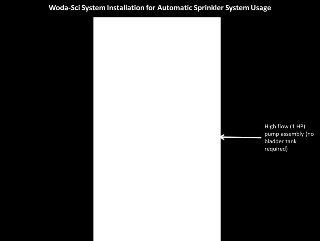
12 Example 2 12

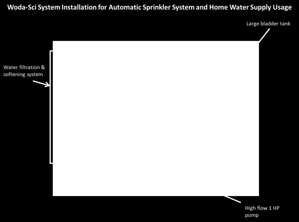
13 Example 3 13
Installation Instructions Table of Contents
 Installation Instructions Table of Contents Pre- Installation of Garage Storage Lift 2 Layout the Garage Storage Lift 3 Installing the strut Channels 3 Install the Drive Assembly 5 Install the Drive Shaft
INSTALLATION AND OPERATING INSTRUCTIONS
 INSTALLATION AND OPERATING INSTRUCTIONS MANUAL TRANSFER SWITCHES FROM 0 Residential Wattage Requirements Appliance Running Watts Add watts for starting Furnace blower, gas or fuel 1/8 hp 300 500 1/8 hp
Mizer Single Pump and Starter Box
 Mizer Single Pump and Starter Box Table of Contents Line Diagram... 2 Overview... 3 Booster Pump Specifications... 3 Water... 3 Electrical... 3 Models... 3 Mounting... 4 Electrical... 6 Motor Rotation...
INSTALLATION GUIDE INSTALLATION GUIDE
 INSTALLATION GUIDE INSTALLATION GUIDE Technical Specifications READ AND SAVE THESE INSTRUCTIONS Check the fan label to make sure it is the correct voltage. Operating voltage Diameter Weight Operating frequency
Poly Electric and Non-Electric Drinkers (Models PCPE, PCPI, PCSE, PCSI, PFL-C, PFL-H, PCHI, PCHE, XCPE)
") Poly Electric and Non-Electric Drinkers (Models PCPE, PCPI, PCSE, PCSI, PFL-C, PFL-H, PCHI, PCHE, XCPE) THANK YOU FOR PURCHASING THIS PRODUCT For questions about this product, or for parts inquiries, please
Poly Electric and Non-Electric Drinkers (Models PCPE, PCPI, PCSE, PCSI, PFL-C, PFL-H, PCHI, PCHE, XCPE) THANK YOU FOR PURCHASING THIS PRODUCT For questions about this product, or for parts inquiries, please
Instruction Sheet. Subject: Installations Instructions. Air Compressor Kits. Importan
 MULTIPLEX 2100 FUTURE, SELLERSBURG, IN 47172 800-367-4233 WWW.MANITOWOCBEVERAGE.COM/US Instruction Sheet Subject: Installations Instructions Importan Read the following warnings before beginning an installation.
JEEVES. JEEVES Installation Manual. Installation Manual The Easiest Do-It-Yourself Dumbwaiter on the Market
 1 888-323-8755 www.nwlifts.com JEEVES Installation Manual The Easiest Do-It-Yourself Dumbwaiter on the Market This manual will cover the installation procedure step-by-step. The installation of this dumbwaiter
INSTALLATION MANUAL 2000WCY
 INSTALLATION MANUAL 2000WCY Pressure Cleaning System spraymastertech.com Spray Master Technologies is a quality product line of Assembled Products Corp. 115 E. Linden Rogers, Arkansas 72756 USA (479) 636-5776
ON DEMAND INSTALLATION GUIDE
 ON DEMAND INSTALLATION GUIDE PICTOGRAMS Each Signifier displayed here is specific to this User Manual. Menu Previous Advance Note Tip Example Barcode Scanner Rotary Heads Drum & Frame Pump Stations Control
Professional Séries. Professional Séries. Model T03828 SUBMERSIBLE SUMP DUPLEX SYSTEM SUBMERSIBLE SUMP DUPLEX SYSTEM. 1/3HP 2400 GPH Head of 20 (6 m)
") Model T0828 Primary pump 1/HP 200 GPH Head of 20 (6 m) SUBMERSIBLE SUMP DUPLEX SYSTEM Professional Séries Discharge: 1 1/2 ABS DWV pipe Electric cable: 9 piggyback type Oil cooled Cast iron construction
Model T0828 Primary pump 1/HP 200 GPH Head of 20 (6 m) SUBMERSIBLE SUMP DUPLEX SYSTEM Professional Séries Discharge: 1 1/2 ABS DWV pipe Electric cable: 9 piggyback type Oil cooled Cast iron construction
Therm-L-Tec Building Systems LLC. Therm-L-Tech. Power Operated Retrofit Kit 230 VAC or 440/480 VAC 50/60 Hz Installation and Setup Manual
 Therm-L-Tec Building Systems LLC Therm-L-Tech Power Operated Retrofit Kit 230 VAC or 440/480 VAC 50/60 Hz Installation and Setup Manual Rev. A 01/2015 Index Index 1 Electrical Requirements for Therm-L-Tec
INSTALLATION INSTRUCTIONS
 1. Note: It is recommended this install be done with a minimal amount of fuel in the tank. This will reduce fuel spills and make installation easier and safer. Draining the tank is recommended. INSTALLATION
TMS Series MP46x Flex Probes* Installation Instructions
 PNEUMERCATOR Liquid Level Control Systems TMS Series MP46x Flex Probes* Installation Instructions Model MP461, MP462 And MP463 Magnetostrictive Flex Probes Installation For: MODEL TMS2000 and MODEL TMS3000
Power Operated Retrofit Kit for Manual Door 230 VAC or 440/480 VAC 50/60 Hz Installation and Setup Manual
 Therm-L-Tec Building Systems LLC Therm-L-Tech Power Operated Retrofit Kit for Manual Door 230 VAC or 440/480 VAC 50/60 Hz Installation and Setup Manual Rev. A 10/2014 Index Index 1 Electrical Requirements
Base Power Infeed Installation for Training Tables with Modular Table Power System
 Base Power Infeed Installation for Training Tables with Modular Table Power System Topic Table of Contents General Safety Warnings Base Power Infeed Usage Electrical Circuits Base Power Infeed - 0 Amp
Asepsis 21 Delivery Unit
 INSTALLATION INSTRUCTIONS for the Console Mounted TM Asepsis 21 Delivery Unit SECTION I - REQUIREMENTS 1. PHYSICAL REQUIREMENTS... 1 2. ELECTRICAL REQUIREMENTS... 1 3. WATER SUPPLY REQUIREMENTS... 1 4.
DEMA BLEND CENTER MODEL 681GAP-3 INSTALLATION INSTRUCTIONS
 1. PARTS CHECKLIST: A. Blend Center Assembly B. Vinyl Supply Tubing with Foot Valve Assembly C. Ceramic Weight D. Vinyl Outlet Tubing E. Screw and Anchor Kit F. Label Card G. Metering Tip Kit 2. INSTALLATION:
Thank you for purchasing the Craven Speed FlexPod Complete Gauge Pod Kit For R56, R58, R59, R60 with Refresh Engines (2011+)
") Thank you for purchasing the Craven Speed FlexPod Complete Gauge Pod Kit For R56, R58, R59, R60 with Refresh Engines (2011+) Before You Start Please read instructions completely before installing. These
Thank you for purchasing the Craven Speed FlexPod Complete Gauge Pod Kit For R56, R58, R59, R60 with Refresh Engines (2011+) Before You Start Please read instructions completely before installing. These
Roll Length (Feet) 6300 Polyethylene Pipe
 6300 Polyethylene Pipe") IRRIGATION Item # Description Tube Length Unit 6291 24" Per Aqua Turret Complete 6293 30" Per Set (comes with pre-cut 6295 36" Per tubing, brass insert & 6297 48" Per aqua turret) 6299 60" Per 6274 Aqua
IRRIGATION Item # Description Tube Length Unit 6291 24" Per Aqua Turret Complete 6293 30" Per Set (comes with pre-cut 6295 36" Per tubing, brass insert & 6297 48" Per aqua turret) 6299 60" Per 6274 Aqua
Poly Electric Drinkers
 Poly Electric Drinkers (Models AHW30, AHW60, AHW80, AHW250) THANK YOU FOR PURCHASING THIS PRODUCT Behlen Country has been in the business of providing quality products for more than 80 years. Our products
Chain/Belt Drive Models PRE-INSTALLATION CONSIDERATIONS
 38968503545. 08/2017 ASSEMBLY/INSTALLATION Chain/Belt Drive Models PRE-INSTALLATION CONSIDERATIONS This opener includes parts and supplies needed for installation in most garages and on most garage doors.
Prodigy HDLV Generation II Manual System Installation Instructions
 Prodigy HDLV Generation II Manual System Installation Instructions Instruction Sheet P/N 1081707A WARNING: Allow only qualified personnel to perform the following tasks. Follow the safety instructions
Please read thoroughly before starting installation and check that kit contents are complete.
 Rear Vision System Mirror Display 2013-Current Ram (Kit part number 1009-9518) Please read thoroughly before starting installation and check that kit contents are complete. Items Included in the Kit: Rear
Installation Manual. Frameworx Tel-E-Foul. September 2017 /
 Installation Manual Frameworx Tel-E-Foul September 2017 / 53-900676-000 Frameworx Tel-E-Foul Installation Manual September 2017 by the Brunswick Bowling Products. All rights reserved. Past Revisions: March
MICRO-AIR DUST COLLECTOR Installation and Operation Manual MODEL RP6-2, RP-3, RP8-2 & RP-3
 MICRO-AIR DUST COLLECTOR Installation and Operation Manual MODEL RP6-2, RP-3, RP8-2 & RP-3 Important: This manual contains specific cautionary statements relative to worker safety. Read this manual thoroughly
DEMA BLEND CENTER MODELS: 637GAP-1 and 637GAP-4 INSTALLATION INSTRUCTIONS
 1. PARTS CHECKLIST: ITEM DESCRIPTION QTY. A. Blend Center Assembly 1 B. ¼ ID X 8 Long Vinyl Supply Tubing & Foot Valve Assembly 4 C. Ceramic Weight 1 D. ½ ID X 6 Long Vinyl Outlet Tubing (For 1 GPM Station
axcs Magellan CMU Installation, Operation and Care Manual
 axcs Magellan CMU 123456789012 123456789012 123456789012 123456789012 Installation, Operation and Care Manual Table of Contents Section I Introduction Introduction... 2 Specifications... 3 Basic Components...
CoolWave 2 Phase Control Board and Cable Replacement Kit
 Instruction Sheet P/N 1102452-02 CoolWave 2 Phase Control Board and Cable Replacement Kit Use the Phase Control Board and Cable Kit to upgrade your CoolWave 2 power supply to the new configuration. NOTE:
Yamaha Apex Moto-R Kill w/jacobson Roll-over valve Installation Instructions
 OFTRacing.com Email Scott Moto 2006-2011 Yamaha Apex Moto-R Kill w/jacobson Roll-over valve Installation Instructions Included Parts: 1 Moto-r Kill wiring harness including Pro Armor tether switch, Jacobsen
Installation Instructions
 CRLOWAMB039A00 CRLOWAMB040A00 CRTRXKIT002A00 ACCESSORY MOTORMASTER I HEAD PRESSURE CONTROL KIT 12.5 TON HEAT PUMP Installation Instructions TABLE OF CONTENTS PACKAGE CONTENTS... 1 PRODUCT USAGE... 2 SAFETY
PERMA ROLL 75. installation instructions Automatic Roll-up Door. note:
 p PERMA TECH, INC. 363 hamburg street buffalo, new york 14204 phone: (716) 854 0707 fax: (716) 854 0774 1 800 362 7325 www.permatechinc.com PERMA ROLL 75 installation instructions Automatic Roll-up Door
CHEVY CAMARO Four panel Sequential LED Taillight kit installation guide
 1978-81 CHEVY CAMARO Four panel Sequential LED Taillight kit installation guide Kit Contents: 4 LED panels 1 power wire with t-tap 2 driver side LED harnesses, 24 2 passenger side LED harnesses, 48 4 LED
NAME OF PAGE. Opening paragraph. header. header. header. header PAGE 1
 NAME OF PAGE PAGE 1 Opening paragraph header header header header 1 1 1 1 2 2 2 2 3 3 3 3 4 4 4 4 5 5 5 5 6 6 6 6 7 7 7 7 8 8 8 8 TABLE OF CONTENTS PAGE 1 PAGE 2-4 Infloor Bpex, Pex Al Pex Tubing and Potable
ROLLING CURTAIN DOOR INSTALLATION, MAINTENANCE & PARTS MANUAL MODEL 944 WARNING
 ROLLING CURTAIN DOOR INSTALLATION, MAINTENANCE & PARTS MANUAL MODEL 944 WARNING Read manual prior to installing door. Overhead doors are large, heavy objects that move with the help of springs under extreme
STEP-BY-STEP INSTALLATION GUIDE
 Battery Backup System STEP-BY-STEP INSTALLATION GUIDE Operating Instructions & Parts Manual ESP25 Please read and save these instructions. Read carefully before attempting to assemble, install, operate
Measurements are expressed in millimeters.
 T-Rex user manual Measurements are expressed in millimeters. 1 Lamp access 2 Focus adjustment 3 Mounting bracket 4 Swivel locks 5 Clamp hole 6 Air vent 190 285 7 AC input & main fuse 8 Microphone 490 164
Installation, Operation and Maintenance Instructions
 FJ-201A Installation, Operation and Maintenance Instructions Oil Belt Skimmers Model 83-1000E, 83-1225, 83-2000E ERIEZ MAGNETICS HEADQUARTERS: 2200 ASBURY ROAD, ERIE, PA 16506 1402 U.S.A. WORLD AUTHORITY
OWNER S MANUAL AND INSTALLATION INSTRUCTIONS
 EmerGen Switch Manual Transfer Switch OWNER S MANUAL AND INSTALLATION INSTRUCTIONS For A Series Models 6-5001, 6-7501, 10-7501, 10-12K1 PLEASE READ THIS MANUAL IN ITS ENTIRETY BEFORE INSTALLING AND/OR
Installing Ignition Coil relay
 Installing Ignition Coil relay Above is a schematic diagram of the coil relay modification. All it really does is, it uses the existing 12 Volt positive that normally powers the coils, to power a relay,
Installation Instructions
 Installation Instructions Jeep JK Unlimited (2007 Present) Mounting Bracket and Air Line System Kit for ARB On-Board Twin Air Compressor (CKMTA12) Made in the USA Kit Contents: 1 Bracket for ARB Compressor
with installation boost GAUGE this manual is for use with systems
 owners manual with installation instructions dynafact boost GAUGE this manual is for use with systems 64050-64054 gale banks engineering 546 duggan avenue azusa, ca 91702 (626) 969-9600 www.bankspower.com
INSTALLATION GUIDE INSTALLATION GUIDE
 INSTALLATION GUIDE INSTALLATION GUIDE Technical Specifications READ AND SAVE THESE INSTRUCTIONS Check the fan label to make sure it is the correct voltage. Operating voltage Diameter Weight Operating frequency
PROPER ELECTRICAL CONNECTIONS
 INSTALLATION 230 Volt 13 ampere 50 Hz The SUITMATE Swimsuit Water Extractor has been designed and manufactured with safety as our primary consideration. Therefore, it is important that the unit be installed
Mobility Mobile Cabinets & Tables
 MOBILITY The Solution to Change... Laboratory technology changes today at an ever-increasing rate. Today's challenge is to provide the longest possible life to your lab. Mott s flexible furniture systems
21511 Commercial Light Kit Part # Qty Description
 21511 Commercial Light Kit Part # Qty Description * 1 Plug in 21563 1 Battery Cable, 90" 8324 6 Cable Ties, 3/16" x 14" 21651 3 Split Rubber Grommet 21652 3 Rosebud Clip -.413/.500 21288 1 Blade Terminal
Assembly Instructions
 Assembly Instructions Part Number Description Model Approx. Assembly Time 99994-0903 Windshield Wiper Kit Mule SX 1 Hour WARNING Improper installation of this accessory could result in an accident causing
TECHNICAL AND SERVICE BULLETIN
 SHEET 1 OF 9 TITLE: INSTALLATION INSTRUCTIONS FOR FAST CHARGE SYSTEM 1. EFFECTIVITY CHARLATTE T135 with POWER PAC CONTROLLERS 2. REASON TO INSTALL FAST CHARGE SYSTEM 3. DESCRIPTION FAST CHARGE AUXILLARY
INSTALLATION INSTRUCTIONS
 INSTALLATION INSTRUCTIONS FUEL PUMP HANGER MITSUBISHI LANCER EVOLUTION X Support: info@radiumauto.com Document# 19-0116 WARNING: DO NOT EXPOSE WORK AREA TO ANY SPARKS OR FIRE. DO NOT SMOKE WHILE WORKING
DEMA BLEND CENTER MODELS: 633GAP INSTALLATION INSTRUCTIONS
 The 633GAP Series Blend Center modular design lets you easily couple together any number of stations to create a system that meets your specific needs. Mix and match both high and low flow units for filling
OFFICE PARTITIONS. Data Port Openings. Use cable tie bracket to dress data cables under panels. STEP 1
 N Power Box Opening Data Port Openings Rear View Front View Remove opening blanks on raceway cover for power and data. If panel contains no electric or data and is used as a pass-thru, leave opening blanks
Installation Kitchen Faucet Filtration System Instructions GXK285JBL
 Installation Kitchen Faucet Filtration System Instructions GXK285JBL BEFORE YOU BEGIN Read these instructions completely and carefully. IMPORTANT Save these instructions for local inspector s use. IMPORTANT
UNPACK AND IDENTIFY THE FOLLOWING PARTS.
 SUT-250-M2 ASSEMBLY REQUIREMENTS *Torque all T-bolt nuts to 35-40 foot pounds. *Check all lights before towing. *Tire pressure not to exceed recommendation on serial tag. *Re-torque wheel nuts after first
Lifeline Medical Systems
 Installation, Operation and Service Manual Lifeline Medical Systems Fully-Automatic Manifold For Use With Liquid Cylinders LQ x HP Liquid x High-Pressure Models Part No. 6-847703-00 Rev. C00 Pg. 1 Introduction
TABLE 1-1 GPM FLOW RATE PROPORTIONER, 1/4 I.D. TUBING Injection Rates For Viscosities Shown Metering Tip Color
 Blend Safe II Dispensing System is a modular, locking dispensing system that allows user to dispense chemicals safely, control dispenser inventory and has the flexibility in the field to meet changing
COMPACT GLYCOL FEED SYSTEMS OPERATION & MAINTENANCE MANUAL
 COMPACT GLYCOL FEED SYSTEMS OPERATION & MAINTENANCE MANUAL Model Number: Service: Serial Number: Installation Date: Installation Location / Application: PLEASE RECORD THE FOLLOWING DATA (Information is
Installation and Service Manual
 RESIDENTIAL PLATFORM LIFTS RPL400 / RPL600 Installation and Service Manual WARNING! STRICT ADHERENCE TO THESE INSTALLATION INSTRUCTIONS IS REQUIRED to promote the safety of those installing this product,
INSTALLATION INSTRUCTION W Track Recessed 120V Flangeless
 W Track Recessed 120V Flangeless WT4-RTL, WT8-RTL, WT12-RTL SAFETY INSTRUCTION Read all of these instructions before installing the track system. Turn off power at main switch before installing or modifying
Cleaning Systems Inc. 2 P Rev:03
 CHEMPOD Table of Contents Overview... 3 Specifications... 3 Dimensions... 3 Weight... 3 Electrical Voltage... 3 Capacity... 3 Product Supply... 3 Pneumatic Supply... 3 Optional Installation Kits... 3 Locating
INSTALLATION AND USER MANUAL
 INSTALLATION AND USER MANUAL SDKIT-730 & SDKIT-734 100% Bolt-On 150 PSI Train Horn System for 2011-2015 F-250 & F-350 Super Duty P/N SDKIT-730 P/N SDKIT-734 Thank you for purchasing a Kleinn Air Horns
SERIES A & AA ROLLER DOORS INSTALLATION GUIDE
 SERIES A & AA ROLLER DOORS INSTALLATION GUIDE THESE INSTRUCTIONS ARE PROVIDED FOR USE BY EXPERIENCED INSTALLERS OF GARAGE DOORS BY UNDER-TAKING THE INSTALLATION OF THIS DOOR, THE INSTALLER UNDERSTANDS
GENERAL INSTALLATION MANUAL
 ---------------------- GENERAL INSTALLATION MANUAL For Outdoor Water Products 35DF-00081 35SH-00001 35DF-00021 Return the Manual to Owner for Future Reference Prior Plumbing Experience required INSTALLATION
ROLLING CURTAIN DOOR INSTALLATION, MAINTENANCE & PARTS MANUAL WINDLOCK MODEL 955WL WARNING
 ROLLING CURTAIN DOOR INSTALLATION, MAINTENANCE & PARTS MANUAL WINDLOCK MODEL 955WL Read manual prior to installing door. Overhead doors are large, heavy objects that move with the help of springs under
R Y T E C. Pharma Seal
 R Y T E C Pharma Seal Installation Manual P.O. Box 403, One Cedar Parkway, Jackson, WI 53037 Phone: 262-677-9046 Fax: 262-677-2058 Rytec website: www.rytecdoors.com Rytec On-line store: www.rytecparts.com
STEPMILL 7000 PT ASSEMBLY INSTRUCTIONS PART NUMBER 27698
 STEPMILL 7000 PT ASSEMBLY INSTRUCTIONS PART NUMBER 27698 1 TOOLS REQUIRED: KNIFE 2-9/16 WRENCHES 5/32 ALLEN WRENCH 1. USE KNIFE TO CUT AND REMOVE PLASTIC STRAPS. TOP COVER PLASTIC STRAPS 2. REMOVE TOP
Installation Instructions: Side Delivery Units BDS-2555
 Installation Instructions: Side Delivery Units BDS-2555 X-Calibur Units Installation Instructions for BDS-2555 X-Calibur Dental Units 7-18-06 BDS Side-Delivery Unit Installation Time: Approximately 1
Water Valve Shutoff. WVS Water Valve Shutoff
 Water Valve Shutoff Monitors flooding from leaking or broken water line Automatic control of main water supply line Form C Relay output for external monitoring devices Visual and audible status indicators
Atomizer 36-DC User Guide
 TECHNICAL INSTRUCTIONS Atomizer 36-DC User Guide SERVICE CASE HUMIDIFICATION Specification Sheet... 2 Installation Guide... 3 Layout Diagram... 4 Maintenance Guide... 5 Wiring Diagram... 6 Pull Sheet...
WIRING DIAGRAM AND INSTALLATION INSTRUCTIONS
 WIRING DIAGRAM AND INSTALLATION INSTRUCTIONS FOR 99101327 ADAPTER KIT Sno-Way, Down Pressure and EIS are registered trademarks of Sno-Way International, Inc. ProControl, MegaBlade, V-Wing, E-Z Switch,
Sky FactoryTM toll free
 Sky FactoryTM www.skyfactory.com toll free 1.866.759.3228 Luminous Virtual Window DC Recessed Installation Packet Installation Packet Includes: Luminous Virtual Window DC Recessed Installation Instructions
Mobility Optima Mobile Workstation
 Optima Mobile Workstation Mobile, adjustable and self contained workstations designed to enhance lab productivity. With a push of a button the work surface adjusts to meet the height demands of individual
INSTALLATION GUIDE INSTALLATION GUIDE
 INSTALLATION GUIDE INSTALLATION GUIDE Technical Specifications READ AND SAVE THESE INSTRUCTIONS Check the fan label to make sure it is the correct voltage. Operating voltage Diameter Weight Operating frequency
MODEL H INSTALLATION INSTRUCTIONS
 WWW.BURCAM.COM 2190 Boul. Dagenais West TEL: 514.337.4415 LAVAL (QUEBEC) FAX: 514.337.4029 CANADA H7L 5X9 info@burcam.com Your unit has been carefully packaged at the factory to prevent damage during shipping.
INSTALLATION INSTRUCTIONS
 Accessory Application Publication No. INSTALLATION INSTRUCTIONS WINCH MOUNT KIT P/N 08L77-HL3-A00 SXS700M4/M2 Honda Dealer: Please give a copy of these instructions to your customer. MII 14607 Issue Date
Q-VAULT Installation Instructions. Q-Tran, Inc. Milford, CT
 QVAULT Installation Instructions QTran, Inc. Milford, CT www.qtran.com QVAULT 342694 Luminairs Landscape Lighting Systems Certified to UL 1838 Standard. 342595 Luminairs Low Voltage Lighting Systems Certified
The Quality of Light TM. MODEL: SSI-600-PDC Controller Operation Manual. Metaphase Technologies Inc. JAN-09
 The Quality of Light TM MODEL: SSI-600-PDC Controller Operation Manual For packaging purposes the line light and controller are shipped separately. The user must make the connection currently according
 Page 1 of 9 Home Account Contact ALLDATA Log Out Help DAN GRIMWOOD DAN GRIMWOOD00002 Select Vehicle New TSBs Technician's Reference Component Search: OK 1985 Dodge Truck D 350 Pickup V8-360 5.9L VIN I
MOTORIZED INSTALLATION INSTRUCTIONS
 MOTORIZED Mega-Pro Swinging Doors Motorized Accordion Strip Doors INSTALLATION INSTRUCTIONS Save-T Roll-Up Bug Screen Save-T Vinyl Roll-Up Screen Save-T Guard Security Gates Save-T Flex-Guard Chain Link
AQUA-LAB AX, BX, TX. CHEMICAL DISPENSING SYSTEM User Manual REV A reva0717
 AQUA-LAB AX, BX, TX CHEMICAL DISPENSING SYSTEM User Manual REV A 4000133 reva0717 Hydra-Flex, Hydra-Flex, Inc. 2017 Inc. 2017 TABLE OF CONTENTS Overview 1 Features 1 Specifications 1 Installation Instructions
OPERATOR, PARTS & INSTALLATION MANUAL BX8893
 AutoStop TM OPERATOR, PARTS & INSTALLATION MANUAL BX8893 AutoStop TM TOWING PRODUCTS DIVISION REQUIREMENTS / INSTALLATION REQUIREMENTS FOR PROPER OPERATION A. You must have a two (2) inch square receiver
CENTRAL VACUUM SYSTEMS
 CENTRAL VACUUM SYSTEMS INSTALLATION INSTRUCTIONS Review this manual before installing the central vacuum system Dynovac Industries 1 800 226 1221 1 403 346 4877 #1, 6841 52 Avenue Red Deer, Alberta T4N
Instruction Book for. ContouR ElECtRol
 Instruction Book for ContouR ElECtRol IMPORTANT SAFETY INSTRUCTIONS When using your video equipment, basic safety precautions should always be followed, including the following: 1. Read and understand
Part Name/Description Part No. PF3000 PF 3000 Pro U-Bracket Short Bracket PF3000 Pro
 Note: Indented items indicate parts included in an assembly listed above Part Name/Description Part No. PF3000 PF 3000 Pro U-Bracket Short 2000105-2 1 PFadvantage Bracket PF3000 Pro 2000773 1 Cable Kit
Installation Instructions
 Installation Instructions Jeep JK 2-Door (2011 Present) Mounting Bracket and Air Line System Kit for ARB On-Board Twin Air Compressor (CKMTA12) Made in the USA Kit Contents: 1 Flat Bracket 1 Formed Bracket
Installing Your 220v J-POD Kit
 Installing Your 220v J-POD Kit NOTE: There are two J-POD versions depending on your pump voltage - 110 volt and 220 volt. MAKE SURE YOU HAVE THE RIGHT VOLTAGE J-POD FOR YOUR. Using software and hardware
MODEL NUMBER: MEDIUM DUTY ONBOARD AIR SYSTEM
 MODEL NUMBER: 10003 MEDIUM DUTY ONBOARD AIR SYSTEM IMPORTANT: It is essential that you and any other operator of this product read and understand the contents of this manual before installing and using
PRODUCT SAFETY NOTICE
 PRODUCT SAFETY NOTICE Congratulations. This vehicle has been equipped with a Firestone air suspension system. This suspension will enhance the vehicle s handling when loaded, however, the vehicle s performance
ALL700/ALL700-CM INSTALLATION INSTRUCTIONS
 ALL700/ALL700-CM INSTALLATION INSTRUCTIONS Aladdin Light Lift, Inc. (256) 429-9700 61 Shields Road (877) 287-4601 Huntsville, AL 35811 www.aladdinlightlift.com Patent #5105349 WARNING: Disconnect power
May 13, 2008 Physics - Electricity & Magnetism. Title: Hot Dog Circuits Demonstration 1. Abstract:
 May 13, 2008 Physics - Electricity & Magnetism Title: Hot Dog Circuits Demonstration 1 Abstract: This demonstration is a way to help students understand Ohm's Law and relationships between power and current.
1. General Safety Information. Silvio V2.0 Assembly Instructions. Assembly. Adjust to the rider.
 Silvio V.0 Assembly Instructions support@cruzbike.com. General Safety Information WARNING to avoid serious injuries:. If you are unsure about fitting, testing and adjusting brakes or gearing on a bicycle,
Table of Contents Next FLO-SAFE Manifold System Pre-Installation Kit Matrx Toll-Free: Technical Support: Fax: Rev.
 FLO-SAFE Manifold System Pre-Installation Kit Instruction Manual Matrx 145 Mid County Drive Orchard Park, New York 14127 716-662-6650 Toll-Free: 800-847-1000 Technical Support: 888-279-1260 Fax: 716-662-8440
Sprayer Control. Manual for SprayLink Cable Installations. Tank. Jet Agitator. Agitator Valve. Diaphragm Pump. Pressure Transducer.
 Sprayer Control Plumbing & Installation Manual for SprayLink Cable Installations Tank Jet Tank Shut-Off Diaphragm Pump Electric Ball s Transducer Strainer Relief Regulating Copyrights 2012 TeeJet Technologies.
CLASS # GAUGE ROUND POWER CORDS
 16 GAUGE ROUND POWER CORDS These 16 gauge, 3 wire orange power cords will stay flexible down to -40. They feature a heavy duty double vinyl jacket insulation and molded male and female ends. The cords
ROSBACK PRINTERS AND BOOKBINDER S MACHINERY Quality Bindery Equipment Since 1881
 PRINTERS AND BOOKBINDER S MACHINERY Quality Bindery Equipment Since 1881 FIELD CONVERSION VACUUM KIT Part No. 220-A-121 (60Hz) Part No. 220-A-121-1 (50Hz) For TRUE-LINE 20" & 26" PERFORATORS MODELS 220A
Ford Meter Box Test Bench Installation Instructions
 DQS Inc. 12/12/18 THE FORD METER BOX COMPANY, INC. CERTIFIED TO ISO 9001:2015 10004466 Ford Meter Box Test Bench Installation Instructions Table of Contents Installation Instructions for Standard, Akron
A B C D E F. b.tools Required (supplied by others) 3/16" Drill Bit 3/8" Wrench Phillips Head Screwdriver
 3/16 Drill Bit 3/8 Wrench Phillips Head Screwdriver") Page 1 of 13 5E.1 Parts List a. Below Deck Automatic Retractable Security Cover Kit (1) Tube End Bearing Plate (A) (1) Rope Reel with Motor Attached (B) (1) Rope Reel Cover (C) (1) Cover Drum (1) Cover
Page 1 of 13 5E.1 Parts List a. Below Deck Automatic Retractable Security Cover Kit (1) Tube End Bearing Plate (A) (1) Rope Reel with Motor Attached (B) (1) Rope Reel Cover (C) (1) Cover Drum (1) Cover
HYDRUS INSTALLATION INSTRUCTION P/N: 3801-EOP AUTO REVERSE / AUTO STOP OPTION KIT FOR HYDRUS 2000 MAIN PANEL
 HYDRUS INSTALLATION INSTRUCTION P/N: 3801-EOP AUTO REVERSE / AUTO STOP OPTION KIT FOR HYDRUS 2000 MAIN PANEL BILL OF MATERIALS: (1) P/N: 4372 - LATCHING RELAY, (1) P/N: 5322 RELAY SOCKET, (4) P/N: 3700-74
Air Conditioner for M915 A0/A1 Truck
 RD-2-4530-0 Air Conditioner for M915 A0/A1 Truck INSTALLATION INSTRUCTIONS Install refrigerant compressor per instructions provided with compressor mount kit. CAUTION: Edges of sheet metal can be sharp!
MICROGUARD 500 EXTENSION REEL TRAINING MANUAL. Greer Company. Greer Company Crane Systems 1 OF18
 MICROGUARD 500 EXTENSION REEL TRAINING MANUAL 1 OF18 TABLE OF CONTENTS MICROGUARD 500 SERIES EXTENSION REEL TRAINING MANUAL EXTENSION REEL OVERVIEW...3 REEL-OFF CABLE LAYERING...3 CHECKING THE REEL-OFF
Trac-Rite ROLLING CURTAIN DOOR INSTALLATION, MAINTENANCE & PARTS MANUAL WARNING
 Trac-Rite Door, Inc. ROLLING CURTAIN DOOR INSTALLATION, MAINTENANCE & PARTS MANUAL WARNING Read manual prior to installing door. Overhead doors are large, heavy objects that move with the help of springs
Arnberg Industries & It s Partners are not responsible for any damage or injury caused by correct or incorrect installation of this transfer switch.
 3560 NE ROZENE WAY BREMERTON, WASHINGTON 98311 (530) 316-1049 Generator Transfer Switch Model; HTS15-MAN & HTS15-MAN-2 Tools Needed For Installation Power drill Wire stripper and cutter (10 to 14 gauge)