MAKE-UP AIR BLOWER INLET MODULE
|
|
|
- Alexandra Hutchinson
- 6 years ago
- Views:
Transcription
1 MAKE-UP AIR BLOWER INLET MODULE This is a self-contained package with a permanent (washable) air filter, electric heating element, modulating element temperature control, and blower. This product has been designed specifically for outside air inlet. The components, finned rod electric elements, inside insulation, etc. have been selected for make-up air. The specification table lists various performance parameters and installation details for the three sizes or models. The model number for your unit is on the bottom cover. All models include the WarmFlo Comfort Module electronic outlet temperature sensor and associated control circuitry to modulate the electric elements for a fixed outlet temperature. This means the electric element is only used to make-up or heat the outside fresh air to the preset temperature point. There is no overheating or inefficient use of the electric element. Also all models include a variable speed blower function, see Installation Setup section for proper blower speed adjustment. Drawings: EH903 p.1 & 2 ES904 ES905 XX017 11/23/ EI903
2 MAKE-UP AIR BLOWER MODULE Model Cabinet Shipping In/Out Voltage kw I Service Drawing Lbs. Duct EM-WH0212J 37L x 13¼H x 13½D V 2.5kW 10 15A ES903 EM-WH0515J 37L x 13¼H x 13½D V 5kW 21 30A ES903 EM-WH1025K 40L x 20½H x 16D V 10kW 42 60A ES904 EM-WH0515J 5 kw EM-WH1025K 10 kw Airflow Temperature Rise Blower SP CFM Temp. Rise ( F) Full Full* Full Full v v Blower SP CFM Temp. Rise ( F) Full Full** Full Full v v *8 x 8ft. pipe outlet, 8 x 8ft. inlet insulated H & C flex. **10 x 12ft. outlet, 10 x 6ft. inlet insulated H & C flex. 11/23/ EI903
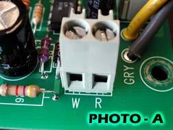
3 Mechanical Installation Zero clearance basically this product is designed for zero clearance, but use the following mounting and spacing criteria: A. Make mounting provisions for a ½ air space at the top. Typically this can be accomplished by having a ½ to ¾ cleat at each end mounting holes. B. The sides, any location, can be in direct contact with wood framing materials. C. No materials shall be in contact with the cabinet housing which has a flame point less than wood (300 F). 1. Select a location which will provide minimal noise vibration and minimal blower noise to the building occupants. 2. The outside hood, inlet damper (see next section under Optional Control Devices), and ducting material are not included with this unit. It is the installer s responsibility to provide the necessary weather protection for the inlet. - Inlet damper is strongly suggested. - Insulated ducting must be used between the outside inlet air hood and the inlet of this unit. 3. Mount unit with a slight air inlet incline (housing outlet end is ¼ higher than inlet end). Depending upon the location within the building, temperature and humidity surrounding this unit, frost or moisture may or may not collect on the metal parts. The inlet damper and insulated inlet pipe will prevent cold air migration and the slight incline will keep this moisture collection at the inlet end. 4. The unit can be mounted within the ceiling (between joists where it will fit) or ceiling hung, at any convenient location between the outside inlet hood and the fresh air discharge connection. - The discharge connection is wherever the conditioned fresh air is distributed within the building furnace cold air return, special ducting, hallway register, etc. 5. The inlet and outlet ducting size is specified according to the model size and is shown in the above table. The 2½ kw unit comes with 8-inch starter collars, but it can be reduced to 6-inch. Electrical Installation Power source see specification table (page 2) for the normal operating current (I) and service size to determine wire size. The exact wire type and wire size is determined by the licensed electrician installer. - Assuming the unit is ceiling hung, open bottom door and remove two small access plates at the outlet end. The J-box marked LINE is the power service connection point. The other access plate and appropriate end plate knockout is for the low voltage control hookup. - All functions are 240, neutral is not required. - The LINE voltage hookup for the 2.5 kw and the 5 kw have a black and red pair for electric elements (heavy wire) and an 18 gauge black and red pair for control and blower. Simply wire nut together with the incoming power service leads. - The LINE voltage hookup for the 10 kw uses a terminal block marked L1 and L2 respectively. Connect incoming power directly to this terminal block. Operating control in its simplest form, this unit turns on and off with a contact closure across R and W. - See photo A R and W is at the end of the PC board. - This on and off control contact applied across R and W depends upon installation requirements and can take on several possibilities end switch within inlet damper, pressure differential switch, current level detection switch, relay across exhaust blower motor, end switch associated with exhaust damper/motor, etc. See Optional Control Devices. 11/23/ EI903
4 11/23/ EI903
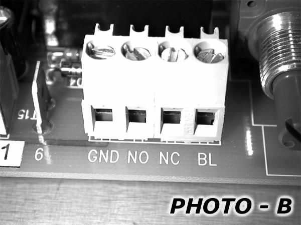
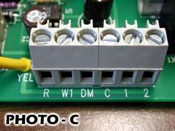
5 Interlock furnace blower relay contact on this unit can be used to operate central furnace blower whenever this units blower is on. See Photo B, connect to the furnace fan center and the G from the roomstat as shown on this table. Comment: When using this connection you cannot use this same contact to operate inlet damper, see below. Blower Inlet (Photo B) Furnace Fan Center Roomstat NO R - BL G - NC - G Optional Control Devices Inlet Damper, Power there are a variety of possibilities and field wiring combinations. A. Power damper with dry contact end switch. 1. Operate damper from its own system turn-on device and power source, independent of this product. - Selected damper needs to be isolated or dry contact end switch. Connect this dry contact to this product s R and W. 2. Operate damper from this product s internal 24-volt transformer and terminal block. In this case there also must be an external turn on and off device. - See Photo C, reference 6-screw terminal block (in this case R and W, Photo A, is not used). - R and W1 contact closure from turn on and off device (see above operating control ). - DM and C two wires going to 24-volt damper motor. - 1 and 2 the isolated contact end switch. Caution: The maximum 24-volt power available is 5VA. B. Provided relay contact, external and independent 24-volt power damper. 1. At terminal block BL/NC/NO is a Form C contact which operates whenever the blower is running, see photo B. Using an external power source, these two screw terminals (BL) and (NO) can be used as a switch contact. 2. This same contact (screw terminal BL and NO) can be used with the onboard 24-volt transformer to operate a 24-volt power damper. Terminal Block 1 Terminal Block 2 Power Damper BL R - NO - Damper 24 GND - Damper common C. Exhaust Blower/Fan Motor Current Switch strip motor power lead through CT and hookup as follows EM-WH***** N/A R N/A GND Switch R Switch W Note: This is an on/off switch only, not level detector. This will not control blower speed. Airflow, or pressure differential, on/off (P/N 5730) this pressure differential switch has two tab terminals, extend these two terminals to the R and W terminal screws, see photo A. - This device can sense the operating of the building exhaust blower so that it will control this product to maintain air balancing. - The differential switch two air tube ports must sense the pressure differential across the exhaust blower. - Factory setting is 0.05 WC. 11/23/ EI903

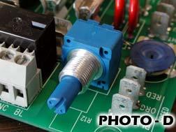
6 Installation Setup Blower Delay/Control the control board has provisions to delay the blower turn on point, allows metal rod electric element to warm up. This is approximately 20 seconds. Conversely, at the end of the R and W control the blower continues to run for approximately 30 seconds to cool off the electric element. The input R and W control and electric element operation can be more effectively observed at the LED monitor lights rather than listening to the blower. LED Monitor Lights WarmFlo Control Board - Green full on electric elements are at full operating power. - Green pulsing whenever the LED is on the elements have power, LED off the elements have 0 volts. - Green full off no power at the electric element. Outlet Temperature On the inside temperature control board is a small screwdriver switch with settings marked 0 through 9. Only settings 0 through 7 are usable (never use 8 and 9). Unless otherwise specified during the time of order, this unit is equipped with a C chip. Assuming this to be the case, the temperature settings relating to the rotary switch positions are: Figure 2 Outlet Temp. Setting 0 = 20 4 = 40 1 = 25 5 = 45 2 = 30 6 = 50 3 = 35 7 = 55 Figure 3 Other Available (Special Order) Temperature Range Chips are as follows: Switch Position E H Photo shows small screwdriver for adjusting this step switch. Blower Speed Adjustment the PC board has a blue shaft adjustment control (see Photo D) for blower speed. Airflow Temperature Rise (page 2) shows airflow at various blower speeds. If you do not need the full CFM of your specific model number unit and desire a larger temperature rise, the blower speed can be reduced with this blue shaft control. However, you must realize the CFM is being reduced and you must maintain the appropriate requirement for balancing the building inlet to the outlet mechanical driven air. Voltage at the blower motor and the static pressure (SP) within the system determine CFM airflow. CFM airflow determines temperature rise. Static pressure is an installation variable and is also a function of airflow. 11/23/ EI903
7 Typically there are two methods for evaluating and adjusting temperature rise: A. Measure static pressure, measure blower voltage, use table The factory calculated information really only has value if you have the ability to determine static pressure within the system and use a volt meter to measure blower voltage. Adjusting the blue shaft control to some arbitrary position does not represent a reliable method of determining airflow. The blower voltage can be measured at the transformer circuit board, find the two wires which lead through the grommet going to the blower motor (tabs Wht and Blu ). B. Operate on a cold day (cold inlet) and do actual temperature rise measurement at full capacity. Using cool air inlet and the following procedure, it becomes quite easy to convert CFM to temperature rise. This procedure may be a little detailed, but if followed step by step the blower speed versus temperature rise can be controlled. Comment: The formula below assumes nominal 240 volts and nominal tolerance electric element. If your application is 208 volts or any other lower voltage, adjust the top number accordingly. EM-WH0515J CFM = Temp. Rise = Temp rise x 1.08 CFM x 1.08 EM-WH1025K CFM = Temp. Rise = Temp rise x 1.08 CFM x Inlet air must be below 40 F. 2. The unit must be setup at full heating capacity, bypassing the outlet sensor modulation control function. This can electrically be accomplished by adding a jumper between the two circuit boards. At the thermostat W screw terminal, add a wire and plug into the E tab on the temperature control board. 3. Insert your temperature sensing probe for the air inlet and the air outlet. Temperature rise is the difference between the two. 4. Suggest beginning with the blue shaft CW, maximum airflow. 5. Condition system for continuous on, either jumper R and W or activate external sensor for closed circuit R and W. 6. Allow at least 10-minute element operation and temperature sensing stability. 7. Slightly decrease fan speed (blue shaft control) to an anticipated setting. Allow temperature stabilization. The change in blower speed and its effect on the electric element, temperature sensing probes, etc. is a very slow process. Again you will probably need to wait at least 5 minutes to recheck the temperature differential and determine your next blower adjustment setting. 8. Continue the above until you arrive at the temperature rise (calculated CFM from the formula) you desire. 9. If you have access to a drop of paint, place on the blue shaft and threaded shoulder to act as a marking point or sealing process to make sure the adjustment is not changed at a later point. 11/23/ EI903
8 Maintenance This unit includes an inlet filter. However, this is a permanent and washable filter. Suggest at least twice per year, remove filter and use standard household water pressure to remove collected dust/debris. - Open smaller door. - Filter is simply held within channels. - Note arrows on filter for washing water flow direction and returned installation airflow direction. - Maintain decal in filter for future reference. Replacement Parts List Cat. # Description EM-WH02 EM-WH05 PCB MAKE-UP AIR BL RLY/TRANS 1 1 PCB WF-CM 2 STG DUCT SENSOR ONLY WFS3 SENSOR DIGITAL ST 17" 1 1 PCB EM-DI 25A RELAY TRIAC SSR 50AMP VAC ELEMENT 240VAC SPIN FIN ELEMENT EM 2500W@240V 8" RND LIMIT O-135/C A@240V DP-CLSD BLOWER/MOTOR 300 CFM 240 V BLOWER/MOTOR 700 CFM 240 PSC LIMIT O-150/O A@240V ST-CLSD PHASE CNT 240AC 6A TABS SSAC FILTER PERM A " X 11" FILTER PERM A "X15.5" 1 11/23/ EI903
9
10
11
12
13 Electro Industries, Inc. Limited Product Warranty Effective February 5, 2009 Electro Industries, Inc. warrants to the original owner, at the original installation site, for a period of two (2) years from date of installation, that the product and product parts manufactured by Electro Industries are free from manufacturing defects in materials and workmanship, when used under normal conditions and when such product has not been modified or changed in any manner after leaving the plant of Electro Industries. If any product or product parts manufactured by Electro Industries are found to have manufacturing defects in materials or workmanship, such will be repaired or replaced by Electro Industries. Electro Industries shall have the opportunity to directly, or through its authorized representative, examine and inspect the alleged defective product or product parts. Electro Industries may request that the materials be returned to Electro Industries at the owner s expense for factory inspection. The determination as to whether product or product parts shall be repaired, or in the alternative replaced, shall be made by Electro Industries or its authorized representative. Electro Industries will cover reasonable labor costs to repair defective product or product parts for ninety (90) days after installation. TWENTY YEAR (20) LIMITED WARRANTY ON BOILER ELEMENTS AND VESSELS Electro Industries, Inc. warrants that the boiler elements and vessels of its products are free from defects in materials and workmanship through the twentieth year following date of installation. If any boiler elements or vessels are found to have a manufacturing defect in materials or workmanship, Electro Industries will replace them. TWENTY YEAR (20) LIMITED WARRANTY ON SPIN FIN ELEMENTS Electro Industries, Inc. warrants that the spin fin elements of its products are free from defects in materials and workmanship through the twentieth year following date of installation. If any spin fin elements are found to have a manufacturing defect in materials or workmanship, Electro Industries will replace them. FIVE YEAR (5) LIMITED WARRANTY ON OPEN WIRE ELEMENTS Electro Industries, Inc. warrants that the open wire elements of its products are free from defects in materials and workmanship through the fifth year following date of installation. If any open wire elements are found to have a manufacturing defect in materials or workmanship, Electro Industries will replace them. Page 1 of 2 XX017
14 THESE WARRANTIES DO NOT COVER: 1. Costs for labor for removal and reinstallation of an alleged defective product or product parts, transportation to Electro Industries, and any other materials necessary to perform the exchange, except as stated in this warranty. Replacement material will be invoiced to the distributor in the usual manner and will be subject to adjustment upon verification of defect. 2. Any product that has been damaged as a result of being improperly serviced or operated, including, but not limited to, the following: operated with insufficient water or airflow, allowed to freeze, subjected to flood conditions, subjected to improper voltages or power supplies, operated with airflow or water conditions and/or fuels or additives which cause unusual deposits or corrosion in or on the product, chemical or galvanic erosion, improper maintenance or subject to any other abuse or negligence. 3. Any product that has been damaged as a result of natural disasters, including, but not limited to, the following: lightning, fire, earthquake, hurricanes, tornadoes or floods. 4. Any product that has been damaged as a result of shipment or handling by the freight carrier. It is the receiver s responsibility to claim and process freight damage with the carrier. 5. Any product that has been defaced, abused, or suffered unusual wear and tear as determined by Electro Industries or its authorized representative. 6. Workmanship of any installer of the product. This warranty does not assume any liability of any nature for unsatisfactory performance caused by improper installation. 7. Transportation charges for any replacement part or component, service calls, normal maintenance; replacement of fuses, filters, refrigerant, etc. CONDITIONS AND LIMITATIONS: 1. If at the time of a request for service the original owner cannot provide an original sales receipt or a warranty card registration then the warranty period for the product will have deemed to begin thirty (30) days after the date of manufacture and NOT the date of installation. 2. The product must have been sold and installed by a licensed electrical contractor, a licensed plumbing contractor, or a licensed heating contractor. 3. The application and installation of the product must be in compliance with Electro Industries specifications as stated in the installation and instruction manual, and all state and federal codes and statutes. If not, the warranty will be null and void. 4. The purchaser shall have maintained the product in accordance with the manual that accompanies the unit. Annually, a qualified and licensed contractor must inspect the product to assure it is in proper working condition. 5. All related heating components must be maintained in good operating condition. 6. All lines must be checked to confirm that all condensation drains properly from the unit. 7. Replacement of a product or product part under this limited warranty does not extend the warranty term or period. 8. Replacement product parts are warranted to be free from defects in material and workmanship for ninety (90) days from the date of installation. All exclusions, conditions, and limitations expressed in this warranty apply. 9. Before warranty claims will be honored, Electro Industries shall have the opportunity to directly, or through its authorized representative, examine and inspect the alleged defective product or product parts. Remedies under this warranty are limited to repairing or replacing alleged defective product or product parts. The decision whether to repair or, in the alternative replace, products or product parts shall be made by Electro Industries or its authorized representative. THESE WARRANTIES DO NOT EXTEND TO ANYONE EXCEPT THE ORIGINAL PURCHASER AT RETAIL AND ONLY WHEN THE PRODUCT IS IN THE ORIGINAL INSTALLATION SITE. THE REMEDIES SET FORTH HEREIN ARE EXCLUSIVE. ALL IMPLIED WARRANTIES, INCLUDING WARRANTIES OF MERCHANTABILITY AND FITNESS FOR A PARTICULAR PURPOSE, ARE HEREBY DISCLAIMED WITH RESPECT TO ALL PURCHASERS OR OWNERS. ELECTRO INDUSTRIES, INC. IS NOT BOUND BY PROMISES MADE BY OTHERS BEYOND THE TERMS OF THESE WARRANTIES. FAILURE TO RETURN THE WARRANTY CARD SHALL HAVE NO EFFECT ON THE DISCLAIMER OF THESE IMPLIED WARRANTIES. ALL EXPRESS WARRANTIES SHALL BE LIMITED TO THE DURATION OF THIS EXPRESS LIMITED WARRANTIES SET FORTH HEREIN AND EXCLUDE ANY LIABILITY FOR CONSEQUENTIAL OR INCIDENTAL DAMAGES RESULTING FROM THE BREACH THEREOF. SOME STATES DO NOT ALLOW THE EXCLUSION OR LIMITATION OF INCIDENTAL OR CONSEQUENTIAL DAMAGES, SO THE ABOVE LIMITATIONS OR EXCLUSIONS MAY NOT APPLY. PRODUCTS OR PARTS OF OTHER MANUFACTURERS ATTACHED ARE SPECIFICALLY EXCLUDED FROM THE WARRANTY. THIS WARRANTY GIVES YOU SPECIFIC LEGAL RIGHTS, AND YOU MAY HAVE OTHER RIGHTS WHICH VARY UNDER THE LAWS OF EACH STATE. IF ANY PROVISION OF THIS WARRANTY IS PROHIBITED OR INVALID UNDER APPLICABLE STATE LAW, THAT PROVISION SHALL BE INEFFECTIVE TO THE EXTENT OF THE PROHIBITION OR INVALIDITY WITHOUT INVALIDATING THE REMAINDER OF THE AFFECTED PROVISION OR THE OTHER PROVISIONS OF THIS WARRANTY. Page 2 of 2 XX017
WARMFLO COMPATIBLE. Upflow EM-WU *** 5* Width 5 = 15 8 = 18. Number of Stages
 WARMFLO COMPATIBLE Upflow EM-WU *** 5* Width 5 = 15 8 = 18 Number of Stages kw Size 10 = 10 kw 15 = 15 kw 20 = 20 kw 14 = 14.4 kw 3 Ph 22 = 22 kw 3 Ph 25 = 25 kw This manual provides the installation information
WARMFLO ANALYZER WF-ANZ7
 WARMFLO ANALYZER WF-ANZ7 NEW UNIT FOR FORCED AIR & TS BOILERS Warranty XX017 HI010 Table of Contents Configuration Information.. 3 Forced Air 5 TS Boiler EB-S, EB-CA, EB-CO, EB-MS. 9 EB-WA, EB-WO, EB-MA,
Model 8144NC Fresh Air Ventilator
 Model 8144NC Fresh Air Ventilator Installation and Operating Instructions MOUNTING BRACKETS WIRE ENTRY LOCATION INTEGRAL PRESSURE PORTS (PORT ON INLET SIDE NOT SHOWN) OVAL OUTLET COLLAR FOR 6" DIAMETER
II DISTRIBUTION & SUBSTATION TYPE C
 CapCheckIII DISTRIBUTION & SUBSTATION TYPE Ca p a c i t o r C h e c ke r Operating & Instruction Manual 1475 Lakeside Drive Waukegan, Illinois 60085 U.S.A. 847.473.4980 f a x 8 4 7. 4 7 3. 4 9 8 1 w e
10 Year Limited Warranty
 Power. On Your Terms. 10 Year Limited Warranty PHI 2.7 TM PHI 3.5 TM 60A SIMPLIPHI POWER, INC. REV020618 10 Year Limited Warranty: PHI 2.7 TM PHI 3.5 TM 60A 24V 48V Limited Pro-Rated Warranty Coverage
Power. On Your Terms.
 Power. On Your Terms. 10 YEAR LIMITED WARRANTY PHI 1310 TM 1 SIMPLIPHI POWER, INC. REV102016 10 YEAR LIMITED WARRANTY: PHI 1310 TM LIMITED PRO-RATED WARRANTY COVERAGE The SimpliPhi Power PHI 1310 as supplied
Installation Instructions
 85-3214 rev. 07 03-11 Installation Instructions Thank you for purchasing this anti-sway bar kit. Please read through these instructions before installation. Rear Anti-Sway Bar Kit Freightliner FL Series
Installation Instructions
 85-4592 rev. 08 02-18 Installation Instructions Thank you for purchasing our sway bar kit. Please read through these instructions before installation. Auxiliary Rear Anti-Sway Bar Kit for Ford F53 part
Installation Instructions
 85-3909 rev. 01 09-09 Installation Instructions Thank you for purchasing this anti-sway bar kit. Please read through these instructions before installation. Rear Anti-Sway Bar Kit for Chevrolet G30 part
Installation Instructions
 85-3511 rev. 04 11-15 Installation Instructions Polyurethane Bushing Kit for Ford F-53 (Front) (replaces OE bushings and brackets) part #4139-127 1-5/8 diameter INTRODUCTION Thank you for purchasing this
TERMS OF USE TERMS AND CONDITIONS. Plumbing and Heating Products (PL-WR)
") TERMS OF USE 1. Watts pricing and product data is subject to change without notice and such changes supersede all previous versions. 2. Watts data is to be used as provided. Watts is not responsible for
TERMS OF USE 1. Watts pricing and product data is subject to change without notice and such changes supersede all previous versions. 2. Watts data is to be used as provided. Watts is not responsible for
Installation Instructions
 85-4209 rev. 05 11-18 Installation Instructions Thank you for purchasing this anti-sway bar kit. Please read through these instructions before installation. Factory Replacement Anti-Sway Bar Kit part #1129-135
GC-1. Roof and Gutter De-Icing Control Installation and Operating Instructions FOR EXTERIOR INSTALLATION ONLY
 GC-1 Roof and Gutter De-Icing Control Installation and Operating Instructions FOR EXTERIOR INSTALLATION ONLY GENERAL INFORMATION The GC-1 heating cable controller has been designed and manufactured for
24V Solar Charger. Instructions READ CAREFULLY Garrymore Ln Missoula, MT
 24V Solar Charger 9889 Garrymore Ln Missoula, MT 59808 888-687-3552 +1-406-549-0769 www.aquacreek.com Instructions PART #: F-045SCH (For use with Revolution, Scout, Titan, Spa Lift Ultra and Spa Lift Elite)
Installation Instructions
 85-3180 rev. 07 03-14 Installation Instructions Thank you for purchasing this antisway bar kit. Please read through these instructions before installation. Front Anti-Sway Bar Kit for the Ford E350/450
HeatChoice TM. Electric Plenum Heater. 05 = 5 kw 8 = = 10 kw 5 = = 15 kw 20 = 20 kw 25 = 25 kw
 HeatChoice TM Electric Plenum Heater U = Upflow D = Downflow EH-*** - * kw Width 05 = 5 kw 8 = 8 0 = 0 kw 5 = 5 5 = 5 kw 20 = 20 kw 25 = 25 kw U.S. and Canadian patent apply No. 4,59,76 and No.,77,52.
Users Manual Certified Series Direct Drive Pump 1-7 LPM
 Users Manual Certified Series Direct Drive Pump 1-7 LPM Safety, Operating, Installation, and Maintenance Instructions 600 S 56 th Street #9 Chandler, AZ 85226 Phone: 480-507-6478 Fax: 480-838-2232 www.fogco.com
Installation Instructions
 85-3414 rev. 02 11-09 Installation Instructions Thank you for purchasing this anti-sway bar kit. Please read through these instructions before installation. Rear Anti-Sway Bar Kit for the Monaco Diplomat
Installation Instructions
 85-3700 rev. 08 05-18 Installation Instructions Thank you for purchasing this antisway bar kit. Please read through these instructions before installation. Front Anti-Sway Bar Kit for the F53 Chassis part
A/C PRESSURE MONITOR INSTALLATION INSTRUCTIONS SYSTEM OPERATION GREEN INDICATOR LIGHT
 A/C PRESSURE MONITOR INSTALLATION INSTRUCTIONS Do not attempt to clean or inspect anything while the engine is running. Cleaning and inspection must be done by a certified mechanic. All A/C service must
Installation Instructions
 85-3209 rev. 07 03-11 Installation Instructions Thank you for purchasing this anti-sway bar kit. Please read through these instructions before installation. Front Anti-Sway Bar Kit for Workhorse W22, Holiday
RANGE HOODS USER INSTRUCTIONS
 RANGE HOODS USER INSTRUCTIONS Model: Advanta Pro III 30 & 36 IMPORTANT SAFETY INSTRUCTIONS Carefully read the following important information regarding installation safety and maintenance. Keep these instructions
Installation Instructions
 85-3910 rev. 03 01-18 Installation Instructions Thank you for purchasing the antisway bar kit. Please read through these instructions before installation. Rear Anti-Sway Bar Kit for Ford F-250/F-350 part
Installation Instructions
 85-3195 rev. 12 04-18 Installation Instructions Thank you for purchasing this antisway bar kit. Please read through these instructions before installation. Part #1139-117 Rear Anti-Sway Bar Kit 1½ diameter
4" ENVIRONMENTAL E-SERIES PUMPS OWNER'S MANUAL. DANGER warns about hazards that will cause. WARNING warns about hazards that can cause
 4" ENVIRONMENTAL E-SERIES PUMPS OWNER'S MANUAL BEFORE INSTALLING PUMP, BE SURE TO READ THIS OWNER S MANUAL CAREFULLY. CAUTION Fill pump with water before starting or pump will be damaged. The motor on
SLIMZONE CLASSIC /
 SLIMZONE CLASSIC 2701-001 / 2701-006 ZONE CONTROL SYSTEM INSTALLATION AND OPERATION MANUAL TABLE OF CONTENTS 1. INTRODUCTION...1 1.1 IMPORTANT NOTE...1 1.2 FEATURES...1 1.3 SAFETY INSTRUCTIONS...1 2. APPLICATION
1401 / 1402 / 1403 ADJUSTABLE TRAILING ARM MOUNT BRACES INSTALLATION OF HOTCHKIS PERFORMANCE ADJUSTABLE TRAILING ARM MOUNT BRACES
 1401 / 1402 / 1403 ADJUSTABLE TRAILING ARM MOUNT BRACES 1401 78-88 GM A/G-BODY / 1402 68-72 GM A-BODY / 1403 64-67 GM A-BODY Thank you for your purchase. Please call us at (562) 907-7757 if you have any
HR-20P Pneumatically Controlled Pressure Regulator
 HR-20P Pneumatically Controlled Pressure Regulator Instruction and Service Manual Hydroplex Corporation 230 West Gloria Switch Rd. Lafayette, LA 70507 337-233-0626 www.hydroplexpumps.com I. General Instructions
P/N# Performance Lowering Springs Installation Instructions
 P/N# 19391 Performance Lowering Springs Installation Instructions Thank you for your purchase of this Hotchkis Performance product. Your Lowering Spring set was designed with the performance and durability
"SPOAU" DEDICATED 100% OUTSIDE AIR UNITS Self Contained Single Package or Split System Units
 "SPOAU" DEDICATED 100% OUTSIDE AIR UNITS Self Contained Single Package or Split System Units Spinnaker Industries Inc. Model Series SPOAU 100% Outdoor Air Systems shall be factory assembled, wired and
SPC-PANEL Simplex, Single Phase Pump Control Panel
 Pump Installation and Service Manual SPC-PANEL Simplex, Single Phase Pump Control Panel Pump Controls for 2 HP Grinder Pumps NOTE! To the installer: Please make sure you provide this manual to the owner
Motorized Stainless 2-Way Valves
 Installation and Operation Manual Motorized Stainless 2-Way Valves Safety Valve ETV Applications WARNING This Heat-Timer valve is strictly an operating valve; it should never be used as a primary limit
UPPER TRAILING ARM REMOVAL
 #1204 MUSTANG UPPER TRAILING ARMS Thank you for your purchase. Please call us at (562) 907-7757 if you have any questions regarding your Hotchkis Performance products. Visit us online @ www.hotchkis.net
Installation Instructions
 85-4341 rev. 04 10-15 Installation Instructions Thank you for purchasing this antisway bar kit. Please read through these instructions before installation. Rear Anti-Sway Bar Kit for Chevy 2500/3500/4500
Read and follow all instructions. Safety can only be ensured if the walker is assembled and operated according to these instructions.
 Aqua Walker 9889 Garrymore Ln Missoula, MT 59808 888-687-3552 +1-406-549-0769 www.aquacreek.com Manual PART #: F-605UW 300 LB. [136 kg] MAXIMUM WEIGHT CAPACITY MANDATORY LEAVE THIS MANUAL WITH WALKER OWNER
Sport Sway Bar Kit Chevy Camaro
 Sport Sway Bar Kit 22109 2010 Chevy Camaro Thank you for your purchase from our new line of Chevy parts. Please call us at 877-4NO - ROLL if you have any questions regarding the service or installation
24V Solar Charger. Instructions READ CAREFULLY Garrymore Ln Missoula, MT
 24V Solar Charger 9889 Garrymore Ln Missoula, MT 59808 888-687-3552 +1-406-549-0769 www.aquacreek.com Instructions PART #: F-044SCH (For use with Pro Pool, Ranger, Ambassador & Pathfinder) MANDATORY LEAVE
Installation Instructions
 85-3207 rev. 03 05-06 Installation Instructions Thank you for purchasing this anti-sway bar kit. Please read through these instructions before installation. Rear Anti-Sway Bar Kit for the Freightliner
7.3L POWERSTROKE BANJO BOLT KIT Fits L Powerstroke Diesel. Installation Guide
 7.3L POWERSTROKE BANJO BOLT KIT Fits 94-03 7.3L Powerstroke Diesel Installation Guide INSPECT CONTENTS OF THIS KIT THOROUGHLY BEFORE STARTING THE INSTALLATION PROCESS! IF YOU FIND A PROBLEM WITH YOUR PACKAGE:
Model GP Triplex Ceramic Plunger Pump Operating Instructions/ Manual
 Model GP6145-3100 Triplex Ceramic Plunger Pump Operating Instructions/ Manual Contents: Installation Instructions: page 2 Pump Specifications: page 3 Exploded View: page 4 Parts List / Kits: page 5 Repair
Sport Sway Bar Kit (22431 ) Subaru Forester INSTALLATION OF HOTCHKIS FRONT SWAY BAR
 Subaru Forester INSTALLATION OF HOTCHKIS FRONT SWAY BAR") Sport Sway Bar Kit (22431 ) Subaru Forester Thank you for your purchase from our new line of Forester parts. Please call us at (877) 4NO - ROLL if you have any questions regarding the service or installation
Sport Sway Bar Kit (22431 ) Subaru Forester Thank you for your purchase from our new line of Forester parts. Please call us at (877) 4NO - ROLL if you have any questions regarding the service or installation
AD-7 THERMAL INDICATING AMMETER
 AD-7 THERMAL INDICATING AMMETER a nd ACCESSORIES Operating & Instruction Manual HD ELECTRIC COMPANY 1 4 7 5 L A K E S I D E D R I V E W A U K E G A N, I L L I N O I S 6 0 0 8 5 U. S. A. P H O N E 8 4 7.
INSTALLATION INSTRUCTIONS
 INSTALLATION INSTRUCTIONS 1301 / 1302 / 1305 / 1306 THANK YOU FOR CHOOSING HOTCHKIS PERFORMANCE PRODUCTS Removal of Stock Lower Trailing Arms 1) Place car on level surface. 2) Support rear of the car on
1313 LOWER TRAILING ARMS CHEVROLET B-BODY
 1313 LOWER TRAILING ARMS 59-64 CHEVROLET B-BODY Thank you for your purchase from our line of classic Chevrolet B-body suspension parts.. Please call us at (877) 4NO-ROLL if you have any questions regarding
6 & 12 Volt Battery and Systems Tester with 100 Amp Load
 6 & 12 Volt Battery and Systems Tester with 100 Amp Load Form No. 841-731 -000 DESCRIPTION This Load Tester tests 6 or 12 volt automotive-size lead-acid batteries under load. It will also test 6 or 12
Installation Procedures Ford F150 2X4, 4X4, Flex Fuel & Eco boost SNS 42
 Installation Procedures 2009-2014 Ford F150 2X4, 4X4, Flex Fuel & Eco boost SNS 42 Warning: Please read directions completely before starting. If you have any questions please contact BMPP before beginning
Non-qualifi ed users should never open or remove covers, as this will expose dangerous voltage points and other serious risks.
 End User Disclaimer End User Disclaimer: United Spa Controls systems have absolutely no end user serviceable parts. United Spa Controls does not authorize attempts by the spa owner/ user to install or
(Special designed for Duro Gas Grill BI)
") DURO FAUX STONE BASE MODEL: 780-0644A (Special designed for Duro Gas Grill 740-3003BI) Installation and User Care Guide IMPORTANT: Save for electrical inspector s use. Installer: Leave installation instructions
DURO FAUX STONE BASE MODEL: 780-0644A (Special designed for Duro Gas Grill 740-3003BI) Installation and User Care Guide IMPORTANT: Save for electrical inspector s use. Installer: Leave installation instructions
Cast Iron WARNING CAUTION. CAUTION Some parts may contain sharp edges especially as noted in manual. Wear protective gloves if necessary.
 Outdoor Fireplace 04201101 04501122 Cast Iron For Outdoor Use Only CAUTION THIS UNIT IS HEAVY! DO NOT assemble without a helper. CAUTION Some parts may contain sharp edges especially as noted in manual.
StormPro BA Series Sump Pump
 Page 1 of 8 Marks & Meanings DANGER: Keep the pump equipment out of the reach of children! Warns that the failure to follow the directions given could cause serious risk to individuals or objects. WARNING:
INSTRUCTIONS FOR INSTALLING AND OPERATING THE UNIVERSAL AUTOSYNC MODEL ASPSS DUAL COMPRESSOR SEQUENCER CONSOLE S/N 1638 AND ABOVE
 COMPRESSOR 1 EMERGENCY SHUTDOWN OFF POWER ON COMP LOADED COM PRESSOR OPERATING HOURS SYSTEM PRESSURE COMPRESSOR 2 EMERGENCY SHUTDOWN OFF POWER ON COMP LOADED COM PRESSOR OPERATING HOURS LEAD/LAG CONTROL
Installation Instructions
 85-5029 rev. 03 06-17 Installation Instructions Thank you for purchasing our anti-sway bar kit. Please read through these instructions before installation. Rear Anti-Sway Bar Kit for Workhorse W22, Holiday
2015 & 2018 Fender Brace Installation Instructions
 2015 & 2018 Fender Brace Installation Instructions Thank you for your purchase of this Hotchkis Performance product. Your Fender Brace set was designed with the performance and durability you ve come to
BC Series Multi-position Air Handler Engineering and Specification Guide (Electric and Water Heat)
") BCAHSG-2 3-Jun BC Series Multi-position Air Handler Engineering and Specification Guide (Electric and Water Heat) 5 YEAR WARRANTY see warranty form for details Contents: Page Number Product Features 2
BCAHSG-2 3-Jun BC Series Multi-position Air Handler Engineering and Specification Guide (Electric and Water Heat) 5 YEAR WARRANTY see warranty form for details Contents: Page Number Product Features 2
Blue Air. Commercial Refrigeration Inc. Installation & Operation Manual Chef Bases
 Blue Air Commercial Refrigeration Inc. Installation & Operation Manual Chef Bases Please read this manual completely before installing or operating this unit! BACB53 BACB71 BACB74 BACB83 BACB86 BACB96
Page Number. Contents: Product Features 2. Physical Data 2. Nomenclature. 3. Blower Performance 3. Electrical Data 4. Warranty.. 6
 TC-SGRAH1-1005 October 05 R Series - High Efficiency Multi-position Air Handler Engineering and Specification Guide (Electric and No Heat) With optional field conversion downflow kit Contents: Page Number
Quest DRY 150. Quest PowerHEPA 500. quest. Read and Save These Instructions. Quest PowerHEPA 500:
 Quest DRY 150 Quest PowerHEPA 500 Read and Save These Instructions This manual is provided to acquaint you with the air scrubber so that installation, operation and maintenance can proceed successfully.
11 GALLON PORTABLE AIR TANK
 11 GALLON PORTABLE AIR TANK Stock Number W10011 OWNER'S MANUAL FOR YOUR SAFETY, please read these instructions carefully and retain them for future use. SPECIFICATIONS Capacity...11 Gallons Recommended
THIS IS OPTIMA S EXCLUSIVE WARRANTY. NO PARTY IS GRANTED EXPRESS OR IMPLIED AUTHORITY TO CHANGE OR ANNUL THIS WARRANTY IN ANY MANNER.
 OPTIMA Batteries, Inc. Limited Consumer Warranty February 1, 2009 OPTIMA Batteries, Inc. warrants to the original purchaser that the battery is free of defects in material and workmanship for the time
Hazardous Location Direct-Drive Exhaust Fans. Operating Instructions & Parts Manual
 Operating Instructions & Parts Manual EN Hazardous Location Direct-Drive Exhaust Fans Models 10D996 thru 10D999, 10E001 thru 10E007, 10E009 thru 10E020, 32ZN53 and 32ZN54 474904 PLEASE READ AND SAVE THESE
Installation, Maintenance, & Repair Series 995 Reduced Pressure Zone Backflow Preventers
 Installation, Maintenance, & Repair Series 995 Reduced Pressure Zone Backflow Preventers RP/IS-995 Sizes: 2" through 2" (5-50mm)! WARNING Read this Manual BEFORE using this equipment. Failure to read and
Installation / Operation Instructions Sunnex ORION Series Exam Lights
 Installation / Operation Instructions Sunnex ORION Series Exam Lights OR-120 OR-127 OR-220 OR-227 Models: OR-300 OR-400 OR-500 OR-600 1. APPLICATIONS The Sunnex ORION Series light was designed specifically
16385 Steering Tie Rods Chrysler A-Body
 16385 Steering Tie Rods 1967-76 Chrysler A-Body Before You Start: Thank you for your purchase from our new line of B & E-Body parts. Please call us at (877) 4NO - ROLL if you have any questions regarding
DUAL WIDEBAND AIR/FUEL RATIO GAUGE Product Numbers: GS-W702W_Dual, GS-C702W_Dual, GS-T702W_Dual
 Installation Instructions Tech Support: 856.768.8300 TechSupport@GlowShiftGauges.com DUAL WIDEBAND AIR/FUEL RATIO GAUGE Product Numbers: GS-W702W_Dual, GS-C702W_Dual, GS-T702W_Dual (1) Gauge (2) Controllers
INSTALLATION INSTRUCTIONS SINGLE HORIZONTAL ACCESS DOOR PANTRY INSERT MANUAL
 INSTALLATION INSTRUCTIONS MODEL #88972 SINGLE HORIZONTAL ACCESS DOOR PANTRY INSERT MANUAL TABLE OF CONTENTS PAGE # INSTALLATION INSTRUCTIONS...................2 CABINET LOCATION GUIDELINES...2 REGULAR
Rear Leaf Spring Kit 24366, Chrysler B-body, Chrysler E-Body
 P Rear Leaf Spring Kit 24366, 24367 66-70 Chrysler B-body, 70-74 Chrysler E-Body Thank you for your purchase from our new line of Mopar parts. Please call us at 877-4NO - ROLL if you have any questions
DPLS2 MANUFACTURED FOR: MITSUBISHI ELECTRIC US, INC. Drain Pan Level Sensor/Control. for use with:
 MANUFACTURED FOR: MITSUBISHI ELECTRIC US, INC. Drain Pan Level Sensor/Control DPLS2 for use with: M-Series MFZ, MS, MSY/Z, SEZ, SLZ, MSZ-FH and MVZ P-Series PCA, PEA, PEAD, PKA, and PVA CITY MULTI PCFY,
14366, Adjustable Strut Rods Chrysler A-Body Chrysler B-Body Chrysler E-Body
 14366, 14385 Adjustable Strut Rods 67-76 Chrysler A-Body 1966-1970 Chrysler B-Body 1970-1974 Chrysler E-Body Thank you for your purchase from our new line of B & E-Body parts. Please call us at (877) 4NO
TALCO FIRE SYSTEMS. LSF Start-Up Instructions. 1) IMPORTANT: Inspect the unit for damage. Report any damage to the freight carrier immediately.
 IMPORTANT: Inspect the unit for damage. Report any damage to the freight carrier immediately.") LSF Start-Up Instructions 1) IMPORTANT: Inspect the unit for damage. Report any damage to the freight carrier immediately. 2) PRE-START-UP: Be sure there is water in the pump. Bleed air at all high points
LSF Start-Up Instructions 1) IMPORTANT: Inspect the unit for damage. Report any damage to the freight carrier immediately. 2) PRE-START-UP: Be sure there is water in the pump. Bleed air at all high points
ESE Series Cast Iron Sewage Pumps
 Owner s Manual ESE Series Cast Iron Sewage Pumps TABLE OF CONTENTS General Safety.................... 2 Specifications..................... 3 Installation.................... 4 & 5 Troubleshooting...................
Installation & Operators Manual
 Installation & Operators Manual Model Serial Number Purchase Date 2007-2008 SegVator, LLC Patent Pending All Rights Reserved Important Safety Information Make sure the vehicle has a properly installed
Reach ins, Freeezers & Refrigerators Installation & Operation Manual
 Reach ins, Freeezers & Refrigerators Installation & Operation Manual BSR23 BSF23 BSR49 BSF49 BSR72 BSF72 IMPORTANT SAFETY INSTRUCTIONS (SAVE THESE INSTRUCTIONS) Visit us on the web at www.blueairinc.com
model ps600 Address all communications and shipments to: FEDERAL SIGNAL CORPORATION
 MODEL: PS600 HZ: 60 A model ps600 installation and service manual for federal model ps600 FEDERAL SIGNAL CORPORATION POWER SUPPLY VOLTS: SERIES: 120VAC FEDERAL SIGNAL CORPORATION UNIVERSITY PARK, IL. U.S.A.
Model BP6150. Triplex Ceramic Plunger Pump Operating Instructions/ Manual
 Model BP6150 Triplex Ceramic Plunger Pump Operating Instructions/ Manual Contents: Installation Instructions: page 2 Pump Specs: page 3 Exploded View: page 4 Parts List / Kits Torque Specifications: page
MOVE ON TO THE REAR BAR INSTALLATION
 22410 STREET SWAY BAR SET 2001-UP LEXUS IS300 Thank you for your purchase from our line of Lexus parts. Please call us at (877) 4NO-ROLL if you have any questions regarding the service or installation
Installation Instructions
 1 Installation Instructions SharkBite Connection System The SharkBite System The SharkBite connection system uses an advanced push-fit design that works in two stages. When the tube is inserted into the
VTC1000 Series Voltage Converter. Installation & Operation Manual
 VTC1000 Series Voltage Converter Installation & Operation Manual INTRODUCTION All new Current Mode switching design offers increased power and reliability in a compact package. Extra input and output filtering
INSTALLATION OF HOTCHKIS FRONT STABILIZER BAR
 22441 FRONT AND REAR SPORT SWAY BAR SET Infiniti G37/S Coupe & G35/S Sedan Thank you for your purchase from our Hotchkis line of suspension parts. Please call us at (877) 4NO-ROLL if you have any questions
PVI 1800/PVI Residential/Commercial Grid-Tied Photovoltaic Inverter WARRANTY MANUAL. Subject to Change REV , Solectria Renewables
 PVI 1800/PVI 2500 WARRANTY MANUAL Residential/Commercial Grid-Tied Photovoltaic Inverter 2009, Solectria Renewables Subject to Change REV 10.09 1 Product Warranty & RMA Policy 1.1 Warranty Policy The Solectria
Cummins N14 Celect & Celect Plus Engine Module. For Agricultural Applications Only. Part # 31200
 1994-2003 Cummins N14 Celect & Celect Plus Engine Module For Agricultural Applications Only Part # 31200 31200_revA Adjustable Switch Agricultural Cummins N14 Engine Module Power and Ground terminals Timing
QUALITY MISTING PUMPS
 TOTALLY ENCLOSED DIRECT DRIVE 60030KH, 60031KH, 60050KH, 60051KH 60100KH, 60101KH, 60150KH, 60151KH MISTING PUMP MANUAL INCLUDING: SPECIFICATION DATA, GENERAL SAFETY PRECAUTIONS, OPERATION, INSTALLATION,
Duplex Booster System Instruction Manual
 Duplex Booster System Instruction Manual ISO 9001 Certified Walrus America Inc Congratulations on your purchase of Walrus IC Series Inverter Control System. Please read all instructions carefully before
Outdoor Nema Enclosure For Dotworkz CoolDome Power Supply Product Code: NM-CDPS. User Manual
 Outdoor Nema Enclosure For Dotworkz CoolDome Power Supply Product Code: NM-CDPS User Manual Revision June 2008 Outdoor Nema Enclosure For Dotworkz CoolDome Power Supply LIMITED WARRANTY FOR DOTWORKZ SYSTEMS
Installation Service Repair Kits Maintenance RP/IS-774/774DCDA/774X/774XDCDA
 Series 774/774DCDA 774X/774XDCDA Double Check Backflow Preventer Double Check Detector Assemblies Sizes: 2 1 2 " - 12" (65-300mm) 774 4" - 12" (100-300mm) 774DCDA 6" - 8" (150-200mm) 774X/774X DCDA Installation
25405 COMPETITION END LINK KIT 2002-UP ACURA RSX, 2004 Subaru STi INSTALLATION OF HOTCHKIS FRONT ENDLINKS
 25405 COMPETITION END LINK KIT 2002-UP ACURA RSX, 2004 Subaru STi Thank you for your purchase from our line of competition parts. Please call us at (877) 4NO-ROLL if you have any questions regarding the
Model 4003 Remote Start Owner s Guide
 Model 4003 Remote Start Owner s Guide 2009 Directed Electronics, Vista, CA G4003L 2009-04 Contents Warning! Safety first...2 What is Included...4 Important Information...4 Your Warranty...4 Using Your
PIVOT BUSHING KIT GM F-BODY
 PIVOT BUSHING KIT 21016 67-69 GM F-BODY 67-69 GM F-Body Pivot Bushing Kit Thank you for your purchase. Please call us at 877-4NO - ROLL if you have any questions regarding the service or installation of
Installation Procedures Shelby GT500 Super Snake SNS 13a
 Installation Procedures 2007-2009 Shelby GT500 Super Snake SNS 13a Warning: Please read directions completely before starting. If you have any questions please contact BMPP before beginning your installation.
22421 SPORT SWAY BAR SET TOYOTA COROLLA
 22421 SPORT SWAY BAR SET 98-01 TOYOTA COROLLA Thank you for your purchase from our line of Corolla parts. Please call us at (877) 4NO-ROLL if you have any questions regarding the service or installation
Mercedes MBE 906/ L & 7.2L Engine Module. Part # Installation Instructions
 1999-2006 Mercedes MBE 906/926 6.4L & 7.2L Engine Module Part # 15000 Installation Instructions 15000_revC 1999-2006 Mercedes 6.4L & 7.2L Engine Module +12 volts red wire. Ground black wire Injector Terminals
FK75 / FK95 Quick Installation Guide
 FK75 / FK95 Quick Installation Guide Battery - Pin 1 2 3 4 5 6 7 Fan Potentiometer 9 10 11 Battery + Fan + Setting the Temperature The controller is set from the factory for use with a 10 degree thermostat,
Anti-roll bar set (pn 2278) Pontiac GTO
 Pontiac GTO") Anti-roll bar set (pn 2278) Pontiac GTO Thank you for your purchase from our new line of GTO parts. Please call us at (877) 4NO-ROLL if you have any questions regarding the service or installation of your
Anti-roll bar set (pn 2278) Pontiac GTO Thank you for your purchase from our new line of GTO parts. Please call us at (877) 4NO-ROLL if you have any questions regarding the service or installation of your
Kit INSTALLATION GUIDE. For maximum effectiveness and safety, please read these instructions completely before proceeding with installation.
 Kit 25690 MN-369 (111512) ECR 8349 INSTALLATION GUIDE For maximum effectiveness and safety, please read these instructions completely before proceeding with installation. Failure to read these instructions
Sport Coil Springs Dodge Magnum, Chrysler 300C Dodge Challenger SRT Dodge Challenger R/T
 Sport Coil Springs 19101 - Dodge Magnum, Chrysler 300C 19107 - Dodge Challenger SRT-8 19108 - Dodge Challenger R/T Thank you for your purchase from our new line of Magnum/300C parts. Please call us at
BMW E46 M3 SPORT SWAY BAR SET # 22826
 BMW E46 M3 SPORT SWAY BAR SET # 22826 Thank you for your purchase from our new line of BMW E46 parts. Please call us at (877) 4NO - ROLL if you have any questions regarding the service or installation
Safety, Installation and Service Manual Models 1952, 1953 & 1972
 Ultraviolet Germicidal Lamps Model 1952 24 Rooftop Unit Model 1953 32 Rooftop Unit Model 1972 Rooftop Unit, Internal Mount Safety, Installation and Service Manual Models 1952, 1953 & 1972 READ AND SAVE
Revised Chevy LS-1 - LS-7 Serpentine Kit. Installation Instructions Kit #20050 (Corvette LS-1 with Power Steering)
") Revised 12-13-08 Chevy LS-1 - LS-7 Serpentine Kit Installation Instructions Kit #20050 (Corvette LS-1 with Power Steering) LS-1/LS-2 Parts List 1-20051-A... Alternator Bracket Body 1 - S144... 5 16 x 7
Revised 12-13-08 Chevy LS-1 - LS-7 Serpentine Kit Installation Instructions Kit #20050 (Corvette LS-1 with Power Steering) LS-1/LS-2 Parts List 1-20051-A... Alternator Bracket Body 1 - S144... 5 16 x 7
Manual Installation & Operation
 Manual Installation & Operation Model: NCxxLxx 12A or 30A Solid State Solar Charging Regulator and 12A Load Controller. 231 Patent #: 5,642,030 Applies Page 1 Warnings When Installing, connect grounds,
PowerFLEX Module Limited Warranty Program
 PowerFLEX Module Limited Warranty Program Global Solar provides a limited warranty applicable to the Global Solar PowerFLEX TM Modules listed below: PowerFLEX TM 6-Meter - - FG-1 BT(M or N)-(275 or 300)
Installation Instructions
 85-3847 rev. 01 09-09 Installation Instructions Thank you for purchasing this anti-sway bar kit. Please read through these instructions before installation. Front Anti-Sway Bar TruTrac Bar Combo Kit for