Blue Sky Sun Visors. RV-10 Installation Instructions. - Portable drill - 9/64 drill bit - 5/64 drill bit
|
|
|
- Amberly Gilbert
- 6 years ago
- Views:
Transcription
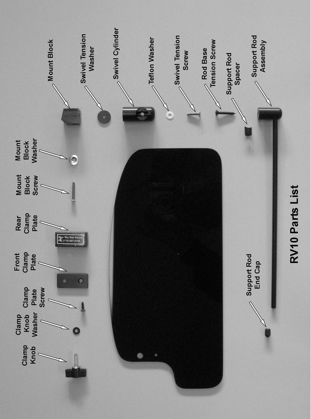
1 Blue Sky Sun Visors RV-10 Installation Instructions Tools needed: - Portable drill - 9/64 drill bit - 5/64 drill bit Degree Countersink Bit - Phillips #2 Screwdriver - Measuring tape - Pencil Step One: Preparation A. See the Parts List Photo at the end of these instructions for the names of the visor parts referred to in the following instructions. B. Loosen the Clamp Knob so that the Visor Screen slides easily on the Support Rod. Remove the Rod End Cap and slide the Visor Screen off of the Support Rod and set the Visor Screen aside. C. Turn the support rod so that it is in line with the swivel cylinder. Step Two: Mount Installation A. We recommend that you install the co-pilot side visor first. Measure a spot 14.5" from the center of the windshield center brace and make a mark on the forward side of the windshield/door frame. This spot should be about the level with the upper edge or the side window (door window) B. Put the 5/64" drill bit in your portable drill. C. With the previously removed Swivel Cylinder/Support Rod assembly in one hand and with the brass insert on the Mount Block facing toward the rear of the plane, push the entire assembly upward and rearward against the windshield/door frame to compress any fabric to the extent possible. While keeping the upward and rearward pressure on the assembly, drill a pilot hole at a slight upward angle through the center of the threaded brass insert with the portable drill as shown in the photo. Proper location of this hole is essential to assure that the entire assembly is free of movement when visors are in use. 1

2 Drilling the Pilot Hole Note: Because of variation of the fiberglass resin/glass in the area where the visor will be attached, it may be necessary to grind the airframe surface so that the mount block is free of movement when installed. When installed, only the lower rear surface and the upper forward surface of the mount block should be touching the airframe. Refer to the drawing below for the correct mount block-airframe contact points. 2


3 D. Once the pilot hole is completed, enlarge the pilot hole with the 9/64 bit from the outside as shown. Keep the drill on a slight downward angle to maintain the hole angle the same as the pilot hole drilled earlier. Drill the Mount Block Screw Hole E. Using the portable drill and countersink bit, bevel the edges of the hole enough to allow the Tinnerman washer to sit flush with the surface of the door/windshield frame. Piloted Countersink Bit F. Take care to avoid snagging the fabric with the drill bit. We suggest some tape around the edges of the hole to protect the fabric from the drill bit. 3

4 G. Insert the #6-32 X 1" flat head countersunk stainless Mount Block Screw through the Mount Block Washer and the windshield frame as shown until it is properly threaded into the brass insert. Take care to avoid cross threading the screw and brass insert. H. Tighten the Mount Block Screw as shown above until the Mount Block has fully compressed any fabric between the Mount Block and the airframe and it is free of fore and aft or side-toside movement. Note: If there is some movement that can t be removed by simply tightening the Mount Block Screw, loosen the screw and consider inserting a small thin wood or plastic shim between the Mount Block and airframe at the correct contact points and then re-tighten the screw until movement is gone. Step Three: Visor Installation and Re-Assembly A. Separate the parts of the Visor Screen Assembly by removing the Clamp Knob and Clamp Knob Washer and unscrewing the Clamp Plate Screw from the Front Clamp Plate. Remove the protective paper by lifting at one of the corners and peel it off both sides. B. With the protective paper removed, re-assembe the co-pilot side Visor Screen Assembly by placing the Visor Screen on a table with the larger end to your left and the smaller tabbed end on the right. Place the Rear Clamp Plate under the smaller end of the Visor Screen and align the smaller holes of Visor Screen and the Rear Clamp Plate. Then place the Front Clamp Plate on top of the Visor Screen so the smaller countersunk hole is directly above the smaller hole in the Visor Screen. Insert the ½" long Clamp Plate Screw in the hole and tighten enough to have solid contact between all 3 pieces. Then align the 3 larger holes in the Front Clamp Plate, the Visor Screen, and the brass insert in the Rear Clamp Plate. Place the Clamp Knob Washer over the larger hole and insert the Clamp Knob through the washer and engage the threads in the Rear Clamp Plate. 4

5 C. Tighten the Clamp Knob about 5 turns and slide the Visor Screen assembly onto the Support Rod. Swivel the Support Rod so that it is in a horizontal position. Then push the Support Rod through the 1/4" hole in the Rear Clamp Plate until it contacts the vinyl Support Rod Spacer at the base of the Support Rod. D. With the Visor Screen assembly hanging loosely on the Support Rod, grasp the larger end of the Visor Screen and push it up and down. It should move with little resistance in a vertical plane. This function allows the top of the Visor Screen to more closely align with the top of the windshield to provide better screening as the Visor Screen is moved along the Support Rod. E. Then tighten the Clamp Knob just enough so that the Visor Screen will not rotate or slide on the Support Rod. When tightened enough, a ½ turn of the Clamp Knob should be sufficient to slide the Visor Screen on the Support Rod. Do not over tighten the Clamp Knob to prevent deforming the Rear Clamp Plate. F. Replace the vinyl Rod End Cap and installation and assembly of your co-pilot side Blue Sky Sun Visors is finished. Step Four: Pilot side Installation Co-Pilot Visor Installed Repeat Steps 1, 2, & 3 above for installation of the pilot side Visor except the larger end of the visor screen will be on the right when attaching the Front and Rear Clamp Plates. 5
6 RV-10 Blue Sky Sun Visors Use and Care Instructions: 1. Blue Sky Sun Visors may be moved to any position in the front or side to reduce the amount of sun reaching occupants or the instrument panel. 2. While the tint of the visors provides significant screening it also reduces visibility to some extent. Consequently, additional care in scanning for other aircraft is important. 3. The amount of light blockage can be adjusted slightly by changing the angle of the visor to the sun's rays. When the visor surface is perpendicular to the light source it has the least sun blocking effect. Adjusting the angle of the Visor Screen will reduce the sun s effect but can also reduce the visibility of objects outside the aircraft. 4. In addition to the movement on the support rod, the visors are also adjustable in a vertical plane within the clamp assembly so that the rounded top of the visor can more closely follow the contour of the windshield bow. Once the visor is in the correct position on the support rod, only turn the clamp knob enough to keep the visor from moving. Overtightening the Clamp knob can, over time, deform the clamp assembly. 5. Loosen the Clamp Knob to slide the visor in and out on the Support Rod and then re-tighten. When the aircraft is not in use, we recommend loosening the Clamp Knob so that the visor can hang loosely on the support rod. 6. In some cases the clamp knob may be inconvenient to adjust in the configuration as shipped. This can be solved by switching the pilot and co-pilot visor screen assemblies. 7. Temperature variation between seasons may reduce the friction between the Mount Block and Swivel Cylinder. Therefore, it may be necessary to adjust the Swivel Cylinder and Rod Base Tension Screws to keep the visors in place when flying. Without the visor screen on the support rod, it should take 5 to 7 oz. (140 to 200 grams) of pressure or tension applied at the end of the support rod to move the visor in a horizontal or vertical direction. 8. The proper swivel tensions are set at the factory. If the Swivel Cylinder rotates too easily, remove the Rod Base Tension Screw and using a #2 phillips screwdriver, slightly tighten the Swivel Tension Screw located inside of the swivel cylinder. No more than an 1/8 of a turn should be required to achieve the proper tension. When properly tensioned, you should not be able to turn the swivel cylinder when gripping it with you bare hand. Retighten the Rod Base Tension Screw until Support Rod Assembly tension is correct. 9. The visor is made of acrylic plastic and can be cleaned by any products compatible with the aircraft windshield. Care should be used to avoid scratching the visor material. A light coat of liquid or spray wax suitable for cars or airplanes can reduce the visibility of fingerprints. All other visor parts are compatible with these cleaning materials. If operated in accordance with the above, the Blue Sky Visor will provide years of dependable service. However, if a part is damaged, individual replacement parts are available. 6
7 7
INSTALLATION INSTRUCTIONS
 INSTALLATION INSTRUCTIONS Document# 19-0038 2004+ Lotus Elise (Series 2) Rear Clamshell Removal Kit Safely support the vehicle. This is a two-person job. Allow 1 to 2 hours for initial disassembly. Have
Installation Instructions BR20 Rear Bumper Replacement Part # 28178T Toyo ta Tundra 2/4WD
 Installation Instructions BR20 Rear Bumper Replacement Part # 28178T 2014-2016 Toyo ta Tundra 2/4WD Excludes Models with B lind Spot Monitoring & Cross Traffic Alert Parts List Item Qty. Part # Description
564 Shadowbox Face (w Screen) Instructions
 Instructions") Packing List Compatibility Face Bottom Shield (2) Face Brackets (8) Screws (#8 x 3/8 Phillips) (5) Screws (#8 x 5/8 hex head) Drill Template 11/64 Drill Bit Items Used with Optional Switch Box (see note
Packing List Compatibility Face Bottom Shield (2) Face Brackets (8) Screws (#8 x 3/8 Phillips) (5) Screws (#8 x 5/8 hex head) Drill Template 11/64 Drill Bit Items Used with Optional Switch Box (see note
Installation Instructions
 Roller & Roman Shades Lifting Systems Cassette and Sure-Lift EZ Lift Cordless EZ Pull Standard and Cassette R-Series Clutch SL-Series Clutch Spring Roller Fascias and Valances 3, 4 Flat and 4 Curved Fascia
Installation instructions for Camaro/Firebird and Nova* Windshield Wiper Systems
 Installation instructions for 1967-69 Camaro/Firebird and 1968-74 Nova* Windshield Wiper Systems The Raingear 1967-69 Camaro/Firebird and 1964-74 Nova wiper system is designed for ease of installation
Section 13. Tail Rotor Drive. RotorWay International A600 TALON Construction Manual. Section 13. Page A
 RotorWay International Page A Tail Rotor Drive Procedures covered in this section: Install driveshafts and gearboxes; install drive belt and tensioner; fabricate and install tail rotor pitch actuator arms;
Wildcat System Instructions
 Wildcat System Instructions NOTE: Most steps contained in these instructions will need to be repeated on the other side of the vehicle. Prior to assembly of windshield it is necessary to establish what
Replacement Top Hardware Installation Instructions
 Replacement Top Hardware Installation Instructions Windshield Channel Installation 1. Position Windshield Channel onto vehicle as shown in Figure 1. 2. Once in position, secure Windshield Channel using
N. 15th Street, Middlesboro, KY TARP-N-GO SYSTEMS INSTALLATION INSTRUCTIONS
 1-800-248-7717 1002 N. 15th Street, Middlesboro, KY 40965 TARP-N-GO SYSTEMS INSTALLATION INSTRUCTIONS Congratulations on your purchase of a Mountain Tarp Tarp-N-Go tarping system. With tarping systems
INSTALLATION GUIDE DODGE PRODUCT CODE:
 INSTALLATION GUIDE 2002-09 DODGE 1500-3500 PRODUCT CODE: 445 & 455 May 17, 2011 TOOLS NEEDED COMPONENTS INCLUDED 3/8" Drill P2 Tip 1/2" Drill Bit #2 Philips Screwdriver Flange(s) x 2 Hinged Lid Track(s)
SPECIALTY TOP CO. STC INSTALLATION INSTRUCTIONS BRONCO ZIPPER FASTTRAC TOP PART # BRONCO
 STC INSTALLATION INSTRUCTIONS BRONCO ZIPPER FASTTRAC TOP PART #331-310 BRONCO 1966-1977 SPECIALTY TOP CO. Thank you for purchasing Specialty's Convertible Top for your Bronco. It has been designed for
Installation Instructions Supertop NX Twill
 Installation Instructions Supertop NX Twill Vehicle Application: Jeep Wrangler Unlimited 2007-current Part Number 54823 Installation Tips Before you begin installing your new Supertop NX Twill, please
Mustang CLASSIC LIGHT BAR INSTALLATION INSTRUCTIONS CDC #
 1990-1993 Mustang CLASSIC LIGHT BAR INSTALLATION INSTRUCTIONS CDC # 101000 Kit Components: 1 Light Bar 4 Bolts ( 5 / 16-18 x 2.5 ) #182010 4 Washer #182005 4 Shims #182009 2 Dark Blue Connectors #182004
Here is the gap seal I used for the flaps, genuine hardware store quality. Note cross sectional shape visible on the right end.
 HOMEBUILT AIRCRAFT DRAG REDUCTION - Case Study with a Lancair IV Part 3 Copyright - Fred Moreno - January 2009 Rev. 1 Portions may be reproduced for private, individual use 3- REDUCED AIRFRAME DRAG FOR
SPECIALTY TOP CO. STC. INSTALLATION INSTRUCTIONS TOYOTA FAST TRAC Z TOP Toyota FJ PART #222-31X 82 1/8" 82 1/8"
 STC INSTALLATION INSTRUCTIONS TOYOTA FAST TRAC Z TOP Toyota FJ-40 1963-1983 PART #222-31X SPECIALTY TOP CO. Thank you for purchasing Specialty's Convertible Top for your Toyota. It has been designed for
RIGGING THE FLIGHT CONTROLS
 RIGGING THE FLIGHT CONTROLS Rigging refers to the installation and adjustment of the rods that move flight surfaces in response to inputs from the controls of the helicopter. These rods are cut to length,
INSTALLATION GUIDE STANDARD PRODUCT CODES:
 INSTALLATION GUIDE STANDARD PRODUCT CODES: 100, 105, 110, 111, 112, 113, 115, 120, 130, 140, 145, 146, 150, 200, 210, 240, 250, 255, 260, 300, 305, 405, 406, 407, 408, 425, 426, 435, 447, 500, 505, 510,
Detroit Speed, Inc. Mini Tubs Camaro/Firebird P/N:
 Detroit Speed, Inc. Mini Tubs 1967-1969 Camaro/Firebird P/N: 040401 The Detroit Speed Mini-Tubs are inner wheel housings designed to accommodate a wider wheel and tire package. They are engineered for
Geared Drives 200Z PSRU Zero Offset Gearbox with Centrifugal Clutch Assembly
 Instructions for Removing and replacing Gen X Gearbox with Geared Drives 200Z Prior to your gear box arriving: Using a strap or chain and an engine hoist to hold your engine up in the mount, remove your
Installation Instructions. QuickSilver Shifter. Fits: GM, Ford, Chrysler Transmissions See Application Guide for Specific Applications Part # 80683
 Installation Instructions QuickSilver Shifter Fits: GM, Ford, Chrysler Transmissions See Application Guide for Specific Applications Part # 80683 WORK SAFELY! For maximum safety, perform this installation
Mallet Nut driver Pop rivet gun Protractor level
 RotorWay International Page A Rev. 2 12/99 Airframe and Landing Gear Procedures covered in this section: Drill airframe bushings; mount front and rear landing gear; install skid tubes; tap body support
COLD AIR INTAKE INSTALLATION INSTRUCTIONS
 COLD AIR INTAKE INSTALLATION INSTRUCTIONS # D760-0030 Fits: 2007-10 135i (E82, E88; with N54 engine) 2007-08 335i/xi (E90) 2007-10 335i (E92, E93; with N54 engine) Congratulations for being selective enough
TCI FastGate Shifter Installation Instructions
 151 INDUSTRIAL DRIVE ASHLAND, MISSISSIPPI 38603 http://www.tciauto.com TELEPHONE: 662-224-8972 FAX LINE: 662-224-8255 E-MAIL: tech@tciauto.com TCI 616541 FastGate Shifter Installation Instructions The
Z-Gate Universal Shifter
 Installation Instructions Z-Gate Universal Shifter Fits: GM, Ford, Lincoln and Chrysler Transmissions See Application Guide for Specific Applications Part #80681 Rev 06/01/2018 WORK SAFELY! For maximum
Stowe Cargo Management System
 Installation Guide Stowe Cargo Management System Table of Contents 1. Pre-Installation (Page 2) a. Notes, Installation Kit contents & Tools needed 2. How to Install the Stowe Cargo Management System (Pages
RS-2 SINGLE ACTION REAR BUMPER WITH TIRE CARRIER INSTALL MANUAL FOR JEEP WRANGLER ALL MODELS.
 RS-2 SINGLE ACTION REAR BUMPER WITH TIRE CARRIER INSTALL MANUAL FOR 2007-2016 JEEP WRANGLER ALL MODELS. Rear Bumper Installation Instructions 1) Remove factory rear bumper, (this includes all tow hitch
One- Touch Installation Instructions
 One- Touch Installation Instructions 1 1 Height Adjustable Pivot w/ screws 9 Upper Work Surface 2 Rail Mount Knobs 10 Back Cover 3 Transformer 11 Center Pivot w/ screws 4 Support Legs 12 Left Monitor Arm
09-12 Dodge 4WD /4 Body Lift
 92RC80000 09-12 Dodge 4WD 1500 1 1/4 Body Lift Thank you for choosing Rough Country for all your suspension needs. Rough Country recommends a certified technician install this kit. Attempts to install
415/417NR NOTEBOOK TRAY ASSEMBLY & OPERATION INSTRUCTIONS
 6703 Zinser Street Schofield, WI 4476 Version Dated: 2/27/1 41/417NR NOTEBOOK TRAY ASSEMBLY & OPERATION INSTRUCTIONS Read all the instructions before beginning. Hardware Pack # 2372 & 031 (Track Hardware)
Installation Instructions Z-Gate Shifter
 Installation Instructions Z-Gate Shifter Part Number 80681 1998, 2001 by B&M Racing and Performance Products The B&M Z-Gate shifter can be used in vehicles equipped with most popular three speed automatic
Installation Instructions
 Equipment Required: Fastener Kit: F Wrenches: 3/4, 15/16 Drill Bits: 1/4 Other Tools: Drill WARNING: Under no circumstances do we recommend exceeding the towing vehicle manufacturers recommended vehicle
To safely lift and install this hardtop, you will need the assistance of at least one other person.! WARNING
 1987-1995 Jeep Wrangler YJ Hardtop with Half Doors Installation Instructions PLEASE READ CAREFULLY BEFORE STARTING INSTALLATION To safely lift and install this hardtop, you will need the assistance of
Page: MEMO: In Figure 3, "2X 1 3/32 [27.78 mm]" was "2X 1 3/32 [2.75 mm]"
![Page: MEMO: In Figure 3, 2X 1 3/32 [27.78 mm] was 2X 1 3/32 [2.75 mm]](/thumbs/73/68816766.jpg "Page: MEMO: In Figure 3, 2X 1 3/32 [27.78 mm] was 2X 1 3/32 [2.75 mm]") 14401 Keil Road NE, Aurora, Oregon, USA 97002 PHONE 503-678-6545 FAX 503-678-6560 www.vansaircraft.com info@vansaircraft.com Service Letters and Bulletins: www.vansaircraft.com/public/service.htm REVISION
14401 Keil Road NE, Aurora, Oregon, USA 97002 PHONE 503-678-6545 FAX 503-678-6560 www.vansaircraft.com info@vansaircraft.com Service Letters and Bulletins: www.vansaircraft.com/public/service.htm REVISION
GT Mustang Shaker
 CD4II3CU CDC Mustang 5.0 Shaker 2011-2014 2011-2014 5.0 GT Mustang Shaker Part #1111-7000-01 Component Check List: Shaker Assembly: Part # 1 - Aluminum Shaker Scoop 183020 1 Upper Air Box 1111-3301-01
COLD AIR INTAKE INSTALLATION INSTRUCTIONS
 COLD AIR INTAKE INSTALLATION INSTRUCTIONS # D760-0029 Fits: 2009-10 335i/xi (E90; with N54 engine) Congratulations for being selective enough to use a Dinan Engineering Cold Air Intake. We have spent many
Installation Guide Current Ford F-250 & Ford F-350 Super Duty. Product Code: 109 & 119
 Installation Guide 2008 - Current Ford F-250 & Ford F-350 Super Duty Product Code: 109 & 119 September 1, 2012 Tools Needed Components Included 3/8" Drill P2 Tip #2 Philips Screwdriver 1/2" Drill Bit Hinged
Detroit Speed, Inc. Mini Tubs Camaro/Firebird P/N:
 Detroit Speed, Inc. Mini Tubs 1967-1969 Camaro/Firebird P/N: 040401 The Detroit Speed Mini-Tubs are inner wheel housings designed to accommodate a wider wheel and tire package. They are engineered for
Rollstar Shade Installation Instructions
 Rollstar Shade Installation Instructions All Lifting Systems Inside or Outside Mount Thank you for purchasing your new Rollstar shade. It has been custom-made from the highest quality materials to the
Installation Guide. Stowe Cargo Management System. Table of Contents
 Installation Guide Stowe Cargo Management System Table of Contents 1. Pre-Installation (Page 2) a. Notes, Installation Kit contents & Tools needed 2. How to Install the Stowe Cargo Management System (Pages
EXTRA 330LX. Specifications: Code: SEA274. Graphics and specifications may change without notice. ASSEMBLY MANUAL
 ASSEMBLY MANUAL EXTRA 330LX Code: SEA274 Graphics and specifications may change without notice. Specifications: Wingspan---------------82.0 in (208.2 cm). Wing area---------------1349.4 sq.in ( 87.1 sq.dm).
ALMOST READY TO FLY. Wing Span in cm. 2
 ASSEMBLY MANUAL ALMOST READY TO FLY MS:X9 Specifications Wing Span --------------------------61.4 in ---------------------------156cm. 2 Wing Area --------------------------606.1 sq.in ------------------
INSTALLATION INSTRUCTIONS HIDDEN WINCH MOUNTING KIT No for Chevrolet & GMC Trucks (for Warn Winches M6000, M8000, XD9000 & HS9500 only)
") INSTALLATION INSTRUCTIONS HIDDEN WINCH MOUNTING KIT No. 61770 for Chevrolet & GMC Trucks (for Warn Winches M6000, M8000, XD9000 & HS9500 only) Warn Light Bar 61090 and many other grille guards can be mounted
INSTALLATION INSTRUCTIONS HIDDEN WINCH MOUNTING KIT No. 61770 for Chevrolet & GMC Trucks (for Warn Winches M6000, M8000, XD9000 & HS9500 only) Warn Light Bar 61090 and many other grille guards can be mounted
Product Drive Cameron Park, CA PH: PRO LAUNCH INSTALLATION INSTRUCTIONS
 12-228 4130 Product Drive Cameron Park, CA 95682 PH: 1.530.642.9488 VIEW INSTALLATION VIDEO AT www.worksconnection.com/prolaunch/ 12-228 PRO LAUNCH INSTALLATION INSTRUCTIONS We at Works Connection Inc.
FUSELAGE ASSEMBLY SECOND SECTION (of three)
") FUSELAGE ASSEMBLY SECOND SECTION (of three) 1 FRONT FLOOR ASSEMBLY The front floor assembly is fabricated from three pieces of the two ply pre-pregnated panel material supplied. The basic floor panel and
FUSELAGE ASSEMBLY SECOND SECTION (of three) 1 FRONT FLOOR ASSEMBLY The front floor assembly is fabricated from three pieces of the two ply pre-pregnated panel material supplied. The basic floor panel and
Roller Shades CORD LOOP. Head Rail, Fascia and No Head Rail. Installation & Care Instructions
 Roller Shades CORD LOOP Head Rail, Fascia and No Head Rail Installation & Care Instructions 152038 H 5/30/2017 GETTING STARTED A few simple tools are required: - Measuring tape - Power drill, drill bits
FOR SIT-STAND WORKSTATION
 INSTALLATION MANUAL FOR SIT-STAND WORKSTATION Weight Capacity: 6.5-24.5 lbs. 6017180 Rev. B Contents Tools Required / Supplied Part Kits / Warnings/Disclaimers...2 Base Installation Clamp Mount Base Location...3
Chapter 52 DOORS -Title
 Chapter 52 DOORS 52-Title Page 1 January 23, 2012 INTENTIONALLY LEFT BLANK 52-Title Page 2 January 23, 2012 LIST OF EFFECTIVE PAGES Chapter Section Page No. Date 52 52-Title 1 January 23, 2012 2 January
Maintenance Information
 Form 16575334 Edition 1 April 2005 Electric Screwdrivers EL, EP and ET 34V DC Series Maintenance Information Save These Instructions WARNING Maintenance procedures have the potential for severe shock hazard
Hurst VMATIC3 INSTALLATION
 FORM 159 8530 07/12 Hurst VMATIC3 3-Speed & 4-Speed Automatic Shifter Catalog #3838530 2012 by Hurst Performance The Hurst Vmatic3 shifter can be used in vehicles equipped with most popular three speed
GenTent 10k/20k StormBracer Edition
 Page: 1 of 20 GenTent 10k/20k StormBracer Edition Product Installation and Safety Manual Free Installation Videos www.gentent.com/installation Read this Manual in Color Online www.gentent.com/manual THANK
Installation Instructions Pro Stick Shifter
 Installation Instructions Pro Stick Shifter Part Number 80701, 80702 & 80706 2012, 2010, 2008, 2001, 1998 by B&M Racing and Performance Products The B&M Pro Stick shifter #80701 and #80706 comes equipped
PRO RATCHET UNIVERSAL SHIFTER
 Installation Instructions PRO RATCHET UNIVERSAL SHIFTER Fits: GM, Ford and Chryslers w/automatic Transmission See Application Guide for Specific Vehicles Catalog # 80842 WORK SAFELY! For maximum safety,
HONEYCOMB & PLEATED SHADES
 INSTALLATION INSTRUCTIONS HONEYCOMB & PLEATED SHADES CONTINUOUS CORD LOOP Thank you for your purchase. This shade has been custom built for you from the highest quality materials. To avoid errors and save
PRO LAUNCH INSTALLATION INSTRUCTIONS
 12-339 4130 PRODUCT DRIVE, CAMERON PARK, CA 95682 PH: 1.530.642.9488 VIEW INSTALLATION VIDEO AT www.worksconnection.com/prolaunch/ 12-339 PRO LAUNCH INSTALLATION INSTRUCTIONS We at Works Connection Inc.
Detroit Speed, Inc. Rear QUADRAlink Conversion Kit Camaro/Firebird P/N:
 Detroit Speed, Inc. Rear QUADRAlink Conversion Kit 1982-92 Camaro/Firebird P/N: 041721 The Detroit Speed Inc. QUADRAlink Conversion Kit, eliminates the factory torque arm configuration. It features no-compromise
FOR WALL MOUNT COMBINATION ARMS
 INSTALLATION MANUAL FOR WALL MOUNT COMBINATION ARMS LIGHT DUTY ARMS HEAVY DUTY ARMS KEYBOARD TRAY VERSION Weight Capacity 4-20 lbs KEYBOARD TRAY VERSION Weight Capacity 8-40 lbs WORKSTATION VERSION Weight
REVISION DESCRIPTION:
 REVISION DESCRIPTION: 1) Page: 12-03 REV 1: Step 1: and Figure 1: Final-Drill s.b. Match-Drill. Step 4: Updated flox mixture description to match later description (removed "peanut butter-like" description).
In area - A -, a proper seal must be made against the top of the window glass.
 Door window, adjusting Page 1 of 3 Audi > B3 > 1994-1998 Body Exterior, Interior 61 - Convertible top, checking and adjusting Door window, adjusting Sections C-C and D-D. Adjust door window so that window
Cellular Shades MOTORIZED SHADE Top Down - Bottom Up. Installation & Care Instructions
 Cellular Shades MOTORIZED SHADE Top Down - Bottom Up ucontact@udoblinds.com 1-855-205-8442 Installation & Care Instructions 152746A 7/2/2018 GETTING STARTED A few simple tools are required: - Measuring
JK REAR BUMPER AND TIRE CARRIER
 JK REAR BUMPER AND TIRE CARRIER Installation Guide AEV30105AA (Updated 5/10/10) Page 1 of 20 Page 2 of 20 EXPLODED VIEW PLEASE READ BEFORE YOU START IN ORDER TO INSTALL THIS PART PROPERLY YOU OR YOUR INSTALLER
IMPORTANT NOTICE: INCLUDED COMPONENTS
 RAMPAGE P R O D U C T S Installation Instructions Part number 680XX Complete Top and Hardware for Jeep Wrangler YJ 1987-95 w/ Full Steel Doors And Cj7 (with modifications) IMPORTANT NOTICE: Carefully read
Mustang. MOD1 Coilover Kit FXXADK0100, FXXADK0200, FXXADK0400 FXXA1K0100, FXXA1K0200, FXXA1K0400
 1964.5-1973 Mustang MOD1 Coilover Kit FXXADK0100, FXXADK0200, FXXADK0400 FXXA1K0100, FXXA1K0200, FXXA1K0400 2276 Research Dr. Livermore, Ca 94550 Ph: (925)-443-6300 E: maier@mikemaierinc.com Page 1 of
Installation Instructions
 Installation Instructions (2) 10-24 Black flathead Allen Screws Tailgate End Front Cover Passenger Side Rail (has inspected by sticker under rail) (4) 10-32 Screws (stainless) Front Cover Exploded View
INSTALLATION INSTRUCTIONS
 INSTALLATION INSTRUCTIONS Accessory Application Publications No. 2004 S2000 AII 26323-31611 Issue Date DEC 2005 PARTS LIST Rear defroster switch Hardtop 3-Pin subharness (If equipped, not used) 4-Pin subharness
WARNING. BX Fiat 500 Abarth/Turbo 2014 Fiat 500c Abarth Installation Instructions
 Attachment Tab Height: 13 Attachment Tab Width: 22 Please read BOTH these and the General Instructions prior to installing or operating this equipment. 1. Blue Ox towing products and accessories are intended
Installation Instructions Sport Shifter
 The B&M Sport Shifter can be used in vehicles equipped with most popular three speed or four speed automatic transmissions. It is equipped with neutral safety and backup light switches, transmission brackets
Parts List. Tools Required
 Assembly, Installation, Operation and Maintenance Instructions Universal Bracket Kit Part # 31563 / 05515 Use with Base Rail Kit 31323 / 07058 Dealer / Installer: Provide a copy of these Instructions to
Service Manual Air Plus Second Stage
 Service Manual Air Plus Second Stage Includes XS Series Second Stage Copyright 2002, Cressi-sub Revised 3/2002 2 Air Plus Second Stage Service Manual Contents BEFORE STARTING... 3 DISASSEMBLY... 3 PARTS
Main Gear Doors (Apr 2009) Matt Kurke, ICS #10288
 Matt Kurke, ICS #10288") Main Gear Doors (Apr 2009) Matt Kurke, ICS #10288 A few thoughts to consider if you are having a problem with the main gear doors retracting and/or fitting properly on your Comanche Read section 6-39 (below)
Main Gear Doors (Apr 2009) Matt Kurke, ICS #10288 A few thoughts to consider if you are having a problem with the main gear doors retracting and/or fitting properly on your Comanche Read section 6-39 (below)
INSTALLATION INSTRUCTIONS
 Rear Vision System Tailgate Emblem Camera Mirror Display 2009-Current Ford F-150 and 2010-Current Super Duty (Kit part number 1008-9527) Kit Contents: Mirror Tailgate Emblem Mount with Camera Interior
Cetra Assembly Instructions
 99877 Revision F- Complete Series Master Packet If you have any questions concerning these instructions, please call Kimball Office Customer Service. 0 Kimball International, Inc. T 800.8.88 F 8.8.800
INSTALL/REMOVAL INSTRUCTIONS: WINDOW LIFT MOTOR
 REMOVAL/INSTALL OF WINDOW REGULATOR (742-269) Ford Mustang 1996 2004 General Tech Tips: Use painter s tape rather than duct tape to secure window. It will not damage paint or leave sticky residue. A plastic
(6) Universal Mounting Brackets (NOTE: same bracket used for left or right side installation) Driver/left Running Board (example only)
 Universal Mounting Brackets (NOTE: same bracket used for left or right side installation) Driver/left Running Board (example only)") PARTS LIST: Qty Description Qty Description 6 Universal Left/Right Mounting Brackets 12 6-1.0mm x 20mm T-Bolts 12 8-1.25mm Clip-On Nuts 12 6mm x 22mm OD x 2mm Flat Washers 12 8-1.25mm x 25mm Hex Bolt 12
PARTS LIST: Qty Description Qty Description 6 Universal Left/Right Mounting Brackets 12 6-1.0mm x 20mm T-Bolts 12 8-1.25mm Clip-On Nuts 12 6mm x 22mm OD x 2mm Flat Washers 12 8-1.25mm x 25mm Hex Bolt 12
Introduction Date: October 2007 Pt No INSTRUCTION KIT JOINER RF 1 KIT COMPONENTS
 KIT COMPONENTS Part Illustration Rear Bracket Description Front Lower Bracket KIT APPLICATION This kit is designed for use on 1595mm / 62 & 1695mm / 66 high cabinet models, incorporating the B, C, D &
INSTALLATION INSTRUCTIONS
 Rear Vision System Liftgate Emblem Camera Mirror Display 2009-2012 Ford Flex (Kit part number 1008-9527) Kit Contents: Mirror Liftgate Emblem Mount with Camera Interior (shorter) Harness Chassis (longer)
Installation Instructions Studio Makeup Station
 Installation Instructions Studio Makeup Station 30" and 36" Models 5-light 30" Studio Makeup Station 8-light 30" Studio Makeup Station 6-light 36" Studio Makeup Station 9-light 36" Studio Makeup Station
Installation Instructions
 Roller & Roman Shades Lifting Systems Cassette EZ Lift Cordless EZ Pull Standard and Cassette R-Series Clutch SL-Series Clutch Spring Roller Fascias and Valances 3, 4 Flat and 4 Curved Fascia 5 Fascia
Technical Techniques. GEN 2 Wake Shaping Devices Installation (Replacing GEN 1) for X2, X10, X25, X30, and X46 X46:
 for X2, X10, X25, X30, and X46 X46:") PARTS REQUIRED: X46: Part #559964 (kit) X46: X2: Part #559960 (kit) X10: Part #559962 (kit) X30: Part #559963 (kit) X2, X10, X30: X25: Part #559961 (kit) TOOLS REQUIRED: Phillips #3 screwdriver or power
PARTS REQUIRED: X46: Part #559964 (kit) X46: X2: Part #559960 (kit) X10: Part #559962 (kit) X30: Part #559963 (kit) X2, X10, X30: X25: Part #559961 (kit) TOOLS REQUIRED: Phillips #3 screwdriver or power
07-11 GM 4WD 1500 P/U 1 1/4 Body Lift
 92RC70100 07-11 GM 4WD 1500 P/U 1 1/4 Body Lift Thank you for choosing Rough Country for all your suspension needs. Rough Country recommends a certified technician install this kit. Attempts to install
Continuous Cord Loop Designer Series Roller Shades
 Shade Maintenance Leveling a Crooked Shade 1. Pull down shade until roller is exposed. Do not pull further to avoid pulling cloth off roller. 2. Stick a 5" strip of masking tape into the roller at opposite
Installation Instructions Right Hand Drive Megashifter
 Installation Instructions Right Hand Drive Megashifter Part Number 80685 1995, 2001, 2006, 2010 by B&M Racing & Performance Products The B&M Right Hand Drive Megashifter is designed specifically for vehicles
INSTALLATION GUIDE. JK Rear bumper & tire carrier. AEV30105AC Last Updated: 10/11/16 US PATENT: D642,502 ; D
 AEV30105AC Last Updated: 10/11/16 JK Rear bumper & tire carrier US PATENT: D642,502 ; D633.024 INSTALLATION GUIDE PLEASE READ BEFORE YOU START TO GUARANTEE A QUALITY INSTALLATION, WE RECOMMEND READING
DL650 Odyssey Luggage Installation Guide
 DL650 Odyssey Luggage Installation Guide Thank you for purchasing Jesse Luggage for your Motorcycle. Our Luggage, handcrafted in the USA, is designed for those with an interest in finding the most durable
Siderolling Tarp Systems Under 9 6 Wide
 Load Loc Select Maximizer Grain Carts Grain Bagger Siderolling Tarp Systems Under 9 6 Wide CRANK STYLE INSTALLATION INSTRUCTIONS MICHEL S INDUSTRIES, LTD. P.O. BOX 119 ST. GREGOR, SK. S0K 3X0 PH:306.366.2184
Stealth Pro Ratchet Shifter
 Installation Instructions Stealth Pro Ratchet Shifter Part Number 81120 & 81121 (see www.bmracing.com for the latest technical product information) 2010, 2006 by B&M Racing and Performance Products The
REVi RX-8 Intake. RX-8 REVi Intake System I PN Installation Instructions. Tools Required:
 RX-8 REVi Intake System PN 18299 Installation Instructions I-18299 Tools Required: Small/Stubby Phillips head screwdriver Small flat head screwdriver Medium Phillips head screwdriver 10mm socket and ratchet
Installation Instructions Megashifter
 Installation Instructions Megashifter The B&M Megashifter shifter can be used in vehicles equipped with most popular three speed or four speed automatic transmissions. Your B&M Megashifter comes equipped
Light Truck MegaShifter
 Installation Instructions Light Truck MegaShifter The B&M Light Truck Megashifter shifter is designed to be used in most light trucks equipped with most popular three speed or four speed automatic transmissions.
06-15 ECU, Battery and Washer Bottle Relocation
 06-15 ECU, Battery and Washer Bottle Relocation On the 2006-2015 MX-5, there is a very narrow middle section between the battery box and the air filter box to remove heat. For the most part, this design
Page: REV 3: Add drill and tap information to Figure 4 DRILL #3, TAP 1/4-28 BOTH ENDS.
 REVISION DESCRIPTION: 1) Page: 32-03 MEMO: Step 4 should not be bold. Fix WD-1213 callout in Figure 3. Page: 32-04 REV 3: Add drill and tap information to Figure 4 DRILL #3, TAP 1/4-28 BOTH ENDS. Add make
IMPORTANT: PLEASE RETAIN THIS INSTRUCTION MANUAL FOR FUTURE REFERENCE
 IMPORTANT: PLEASE RETAIN THIS INSTRUCTION MANUAL FOR FUTURE REFERENCE 2009 Toyota RAV-4 Stainless Steel Mesh Grilles L 30 G8P Fine Mesh Part #30-002-09 Quantity Description Part No. Upper Mesh Grille (includes):
INSTALLATION INSTRUCTIONS REPAIR SEAL KIT PowerSurvivor 40E
 INSTALLATION INSTRUCTIONS REPAIR SEAL KIT PowerSurvivor 40E PURPOSE OF THE KIT The Repair Seal Kit should be installed after 1000 hours of operation. It should be installed regardless of whether or not
Myriad Keyboard and Mouse Tray, Articulating Arm Installation Instructions
 670 Zinser Street Schofield, WI 54476 Version Dated: 4/2/15 Myriad Keyboard and Mouse Tray, Articulating Arm Installation Instructions Read all the instructions before beginning. Hardware Pack # 50525
57-1. Front door. Tools. Special tools and equipment. T Socket 3320/2 Bit insert for Socket T Assembly tool
 57-1 Front door Tools Special tools and equipment T 10011 Socket 3320/2 Bit insert for 3320 3410 Socket T 10034 Assembly tool 57-2 Front door, assembly overview Note: The instrument panel must be removed
INSTALLATION INSTRUCTIONS HONDA CBR250R P/N: HB01075
 INSTALLATION INSTRUCTIONS HONDA CBR250R P/N: HB01075 IMPORTANT: PLEASE GIVE CUSTOMER ENCLOSED INFORMATION! Thank you for your purchase of our HeliBars. They are designed to increase your long distance
INSTALLATION & OWNER S MANUAL
 INSTALLATION & OWNER S MANUAL CAB INSTALLATION INSTRUCTIONS JOHN DEERE 4000 SERIES (4500/4600/4700) (4510/4610/4710) (4120/4320/4520/4720) HARD SIDED CAB ENCLOSURE (p/n 1JD4120AS) SOFT SIDED CAB ENCLOSURE
TOYOTA FJ CRUISER AIR DAM/LIGHT BAR Preparation
 Preparation Part Number: PT278-35071 Kit Contents Item # Quantity Reqd. Description 1 1 Air Dam / Light Bar Hardware Bag 1 Contents Item # Quantity Reqd. Description 1 2 Screw, M6x33mm, Wafer Head 2 2
Technical Support (707)
") Installation Instructions UNIMATIC SHIFTER Fits: GM, Powerglide, Ford and Chrysler Transmissions See Application Guide for Specific Vehicles Catalog # 80775 WORK SAFELY! For maximum safety, perform this
Installation Instructions UNIMATIC SHIFTER Fits: GM, Powerglide, Ford and Chrysler Transmissions See Application Guide for Specific Vehicles Catalog # 80775 WORK SAFELY! For maximum safety, perform this
Suzuki Samurai to Toyota Front Spring Swap Kit, with Missing Link Shackles (SKU#SSP-TSFM) Installation Instructions
 Installation Instructions") Suzuki Samurai to Toyota Front Spring Swap Kit, with Missing Link Shackles (SKU#SSP-TSFM) Installation Instructions CAUTION: Safety glasses should be worn at all times when working with vehicles and related
Suzuki Samurai to Toyota Front Spring Swap Kit, with Missing Link Shackles (SKU#SSP-TSFM) Installation Instructions CAUTION: Safety glasses should be worn at all times when working with vehicles and related
Adjusting Carbs For Re-Jetting (Procedure written for an Intruder 1500 LC) NEWLY UPDATED: APRIL 2003
 NEWLY UPDATED: APRIL 2003") SECTION ONE: Get Prepared - Tools Adjusting Carbs For Re-Jetting (Procedure written for an Intruder 1500 LC) NEWLY UPDATED: APRIL 2003 Courtesy of: Half-Crazy Get a manual impact driver (the kind you hit
SECTION ONE: Get Prepared - Tools Adjusting Carbs For Re-Jetting (Procedure written for an Intruder 1500 LC) NEWLY UPDATED: APRIL 2003 Courtesy of: Half-Crazy Get a manual impact driver (the kind you hit