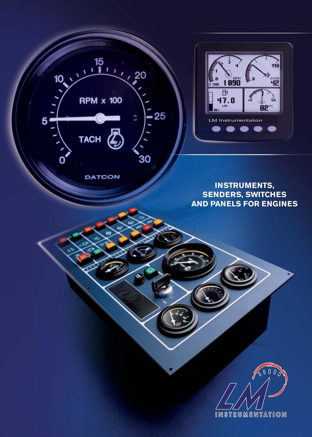
DASHBOARDS LM Instrumentation Dashboards Maxima Clusters...7 ENGINE MONITORING AND CONTROL MODULE...8. MULTI-FUNCTION DISPLAY CANbus...
|
|
|
- Sophie Bradley
- 6 years ago
- Views:
Transcription
1
2
3 Contents DASHBOARDS Dashboards Maxima Clusters...7 ENGINE MONITORING AND CONTROL MODULE...8 MULTI-FUNCTION DISPLAY CANbus CANbus INSTRUMENTS HOURMETERS VOLTAGE, CURRENT, TEMPERATURE, PRESSURE, LEVEL AND ACCESSORIES Presentation of the 52mm diameter gauges...18 Ammeters, Voltmeters, Battery controllers...19 Temperature gauges and senders...20 Exhaust temperature monitoring systems, temperature switches, adaptors Pressure gauges and senders, pressure switches, thread adaptors Mechanical products range...27 Fuel and water level gauges, senders and switches VDO Match gauges and senders by Datcon AST Jorda gauges and senders (including Jaeger match parts) Accessories for 52mm diameter...46 Digital temperature and pressure gauges ELECTRONIC SWITCHES FOR 52MM DIAMETER PRODUCT RANGE TACHOMETERS AND SPEEDOMETERS Tachometers and tacho-hourmeters with 86mm diameter Accessories for 86mm diameter...56 Tachometers with 52mm diameter Accessories for 52mm diameter tachometers...59 Speedometers...60 Magnet pick-up...61 Pulse generator Limit speed switches Adjustable digital speed counter...66 Digital tachometers and speedometers Self powered digital counter, rotation stop detector...69 PORTABLE TACHOMETER AND THERMOMETERS DASHBOARD COMPONENTS Key switches...73 Battery switches...74 Switches and warning lights Relays, hole blanks...78 Buzzers...79 NORIS PRODUCT RANGE Presentation...80 Temperature senders...81 Thermocouple for exhaust temperature...82 Pressure senders 4-20mA or 0-10V...83 Speed sensors and tacho-generators Limit value switches for temperature, voltage, current, frequency, or speed Converters (transducers) for temperature, voltage, current, frequency, or speed Analogue indicators for speed, temperature, pressure Marine propulsion shafting speed measurement...96 BATTERY CHARGERS...97 page 1


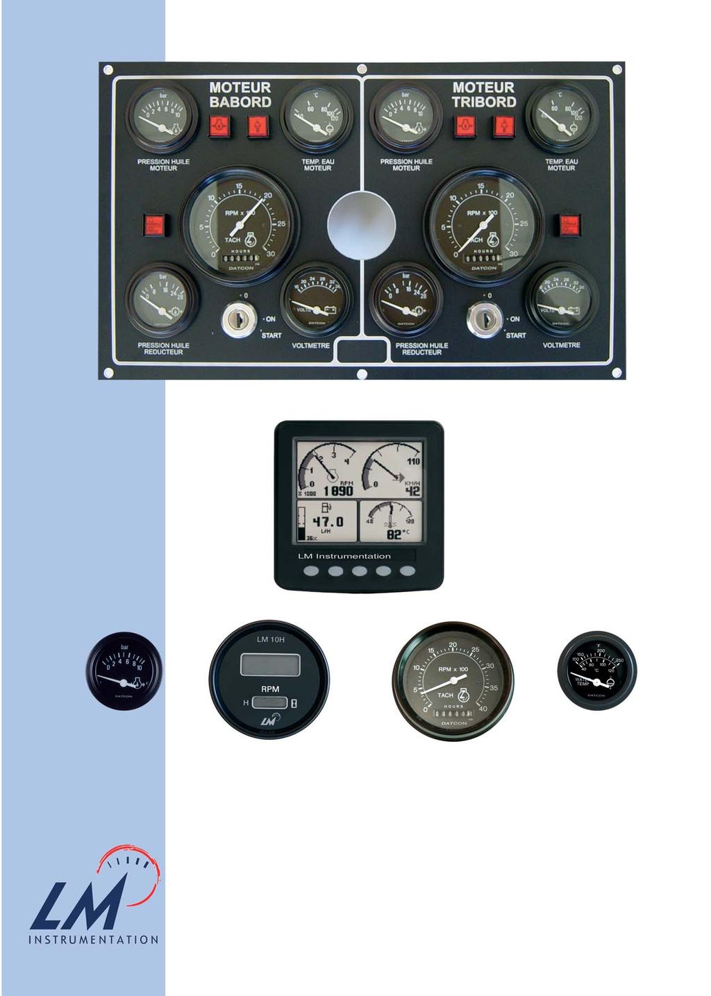
4 DASHBOARDS Dashboards develop and manufacture custom and standard dashboards Standard dashboards To built in 220 x x x CARQUEFOU - FRANCE page 2

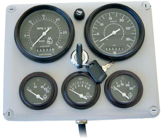
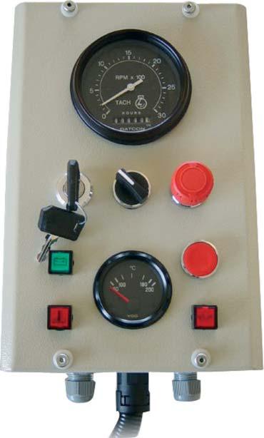
5 Wall mounting page 3
6 Custom dashboards page 4


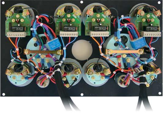
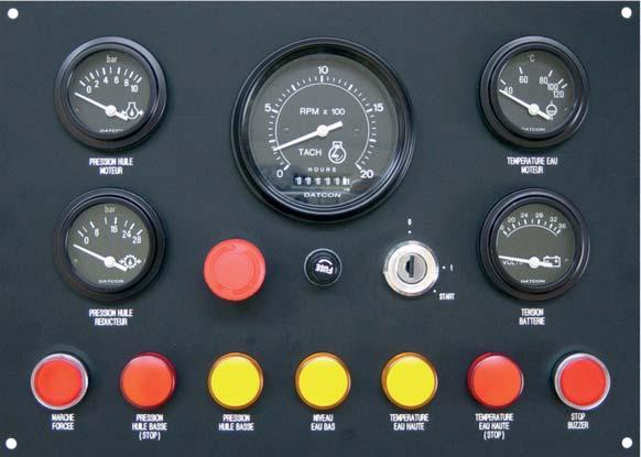
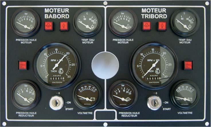
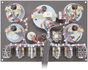
7 Complete panels sets Main control panel Machinery panel Harnesses page 5


8 Complete panels sets page 6


 Compatino Standard (minimum")
9 Maxima Technologies Clusters Maxima Technologies develop and manufacture clusters for OEM s appliances (minimum quantity required). We can supply custom solutions and adjustable standards (limited development and investment) Universal Standard (minimum quantity required) Compatino Standard (minimum quantity required) Custom Cluster (minimum quantity required) page 7

10 ENGINE CONTROL MODULE MC 704 The MC 704 has been designed to suit extreme working conditions of mobile and stationary engines. This compact unit performs two critical cost saving functions: - it automatically shuts down the engine due to failure - it informs the operator what caused the malfunction via one of the four led s Technical data Dimensions: 72x72x110mm Cut for flush mount: 66x66mm Flange mount or panel mount Rugged aluminium housing Operating voltage 8 to 32V Current input 30mA Sealing class IP54 Temperature range 40 to +85 C Electrical connection via one locked multiple plug : Output : (3.5A short circuit protected): solenoid (fuel shut off), alarm (audible, visual). Inputs : oil pressure switch, temperature switch, alternator / D+, auxiliary (air filter, V-belt, water pressure switch ), remote stop. Temporary errors will be ignored and stay accumulated for 10 seconds. If they exceed 3 seconds in total in this time the engine will be shut down automatically and the alarm will be activated. page 8 Hourmeter Preheat P/N 4842 P/N 4843 P/N 4142 P/N 4756

11 CANbus MULTI-FUNCTION DISPLAY CANtrak The CANtrak has established a new standard for intelligent, multi-function displays. The ideal man-machine interface, it is easily configured via the application of user-friendly software, to measure, display, store, process and transmit data. 2 versions available: GEM (for monitoring J1939 and J1587 Engine Data) 2600 OPEN Display features Large FSTN display, 160x128 pixels Adjustable contrast and backlight Soft function push-keys for rapid display selection, fault handling and set-up Audible alarm: 4 Khz internal sounder Communications: Full CAN 2.0B controller/part. RS232 / RS422.RS485 Power input 10 to 32VDC Power consumption: max 300mA at 12VDC Connection: Integral Deutsch 12 way connector (DT04-12PA) Degree of protection: IP67 Operating temperature: -25 C to +75 C Storage temperature: -40 C to +80 C Shock resistance: 30g Vibration resistance: 3g Color: anthracite grey Dimensions: 110mmx110mmx38,5mm deep Mounting: front or rear page 9


 available with relevant message such as too high / too")

12 FOR YOUR ENGINE CANtrak GEM (Generic Engine Monitoring) Plug-and-go solution for the display of J1939 and J1587-transmitted engine and transmission data. The GEM offers user selectable icon based display layouts as well as including a comprehensive multi language text based fault warning and acknowledgement system. Key features Displayed data if received from the engine and transmission ECU s: Electrical Fuel Distance Pressure Temperature Percentage Speed Time Faults: (suspect parameter number) available with relevant message such as too high / too low. Fuel pressure, water in fuel, coolant level, engine speed GEM Software can be fully customised to meet exact requirements. From adding customised logos to adding parameters and screen formats for example. page 10

 which is a programmable sensor module that interfaces between various electronic sensors and J1939 or NMEA 2000")
13 OPEN VERSION CANtrak 2600 CANtrak 2600 OPEN version is an ideal man-machine interface. It is easily configured via the application of user-friendly software, to measure, display, store, process and transmit data. Key features Micro Controller Siemens bit/20Mhz FLASH Memory : 512K bytes RAM : 128K bytes EEPROM: 128 bytes Communications: Full CAN 2.0B controller / port.rs232 / RS422. RS485 If needed we can also supply you a CANtrak Configurable Input Module (CCIM) which is a programmable sensor module that interfaces between various electronic sensors and J1939 or NMEA 2000 Network. Self programming by costumer : Software Development Kit (SDK): All software for CANtrak 2600/2610 is written in C The SDK makes available an extensive library that covers all the aspects required to develop and create a new application. Programming by our team: Do not hesitate to contact us with your project. Our development team can ensure software development and also training. CANtrak GEM (J.1939) P/N : CANtrak OPEN P/N : 6020 Connector kit for CANtrak P/N : 6023 page 11

14 DIRECT DATA-BUS INSTRUMENTS : DDBI DDBI (gauges, tachometers and speedometers) provides a direct connection to the SAE J1939 or J1708/1587 vehicle bus. No instrument controller or gateway required. Units can be individually connected to the bus or run in series. This architecture ensures easy installation and lower installed- system cost. General Features : J1939 x J1708/1587 inputs Reinforced plastic case Integral 6 or 12 pin sealed Deutsch connectors Led black lighting (amber) Lighted pointer Plastic diffuser for standard black dials, white on blackgraphics Stepper motor drivers, 270 sweep Operating voltage 12 VDC (10-16) x 24 VDC (20-32) Operating temperature: -40 C to + 85 C 270 sweep when power on Black anodized SAE step bezel Other specifications according to SAE Ensemble de base/ Spécifications page 12


 Diameter 52 mm Water temperature 12V P/N 14.")
 Diameter 52 mm Accessory : Deutsch 270mm harness P/N")
15 Tachometer RPM 12V P/N with LCD display (shows fault codes and 24V P/N various engine operating parameters, including hourmeter) Diameter 86 mm Oil pressure gauge V P/N Bars with integral led warning light 24V P/N (pre-set at 0.7 Bar) Diameter 52 mm Water temperature 12V P/N gauge C with integral led warning light 24V P/N (pre-set at 105 C) Diameter 52 mm Accessory : Deutsch 270mm harness P/N with 6 pin connector. Consult us for other DDBI instruments : Speedo-odometer km/h Fuel level gauge (bus or analog input) Voltmeter page 13


16 HOURMETERS Electronic Quartz Hourmeter P/N : mm diameter Record to: ,9 hours, operation warning light Operating voltage: 10/32 VDC Mounting ring Water resistant front Operating temperature: -40 C + 85 C Electrical connections: 6.35 TAB Terminals Hourmeter with pointer 52 mm diameter Operating voltage : VDC Record to hours 1 pointer rotation = 1 hour Operating temerature: C Mounting by bracket Water resistant front IP65 Connection: 2 x 6.35 mm Tabs page 14 P/N :


17 LCD Hourmeter 52 mm diameter Record to: ,9 hours Operating voltage: 8/28 VDC Operating temperature: -40 / +85 C 6 digits LCD display Connection: 2 x 6.35mm tabs Mounting by bracket P/N : Engine powered hourmeters Those hourmeters do work with W alternator or battery ignition signal input. 52 mm diameter Record to: ,9 hours Mounting by automatic bracket Waterproof on front Operating temperature 40/ +80 C Connection on 6.35mm tabs Connection on Magneto Ignition P/N Connection on W alternator P/N page 15

18 Vibration hourmeter The hourmeter records the running time of engines, vehicles, machines, which vibrate during operations. 52 mm diameter Record to hours Mounting by bracket Water resistant front IP65 Do not need any power input Supplied with damping ring. Dimensions P/N LCD vibration hourmeter 6 digits LCD display 52 mm diameter Record to ,9 hours Mounting by bracket page 16 Do not need any power input P/N

19 Hourmeter for alternating current 50Hz Features Dimensions on front: 52x52mm Diameter hole 50,2mm or square 45,2mm Record to 99999,99 hours Hourmeter 52x52mm 24VAC 50Hz P/N Hourmeter 52x52mm 48VAC 50Hz P/N Hourmeter 52x52mm 110VAC 50Hz P/N Hourmeter 52x52mm 220VAC 50Hz P/N Hourmeter 52x52mm 380VAC 50Hz P/N Accessorie Gasket for hourmeter 52x52mm P/N Hourmeter self power Type LM25 Diameter: 86mm Record to: ,99 hours Mounting bracket Water-resistant front Operating temperature: 0 C +50 C Autonomy 8 years lithium battery Totals when its terminals are connected Reset Dimensions and connections P/N page 17

20 VOLTAGE, CURRENT, TEMPERATURE, PRESSURE, LEVEL AND ACCESORIES 52 mm diameter gauges. Presentation Outlook Glass fiber plastic housing, shock-resistant Wtareproof front Glass lenses White on black lettering/ symbols SAE anodised aluminium bezel Connection threads Installation hardware: mounting brackets and nuts P/N Features Operating voltage for 12 volts instruments: 10 to 16 VDC also works in 24 Volts with adapter P/N Angular degrees: 90 for pressure and level gauges, 100 for temperture gauges. Operating temperature: -40 C +85 C Typical gauge installation page 18


 Current rating 2A at 12 or 24 Volts Sealing class: IP65 in front In option: empty alarm at 20-25 % residual")
21 Ammeters - Voltmeters Ammeters 20 A P/N A P/N A P/N Beyond 60A, use ammeters with a shunt. Scale P/N Ammeter P/N Shunt 100 A A A A Voltmeters 8-18 Volts P/N Volts P/N Accessories Light kit 12 volts : P/N Light kit 24 Volts : P/N Water resistant gasket for 52 mm diameter gauge : P/N Battery discharge gauges Those gauges do control the battery discharge with or without alarm. Features All type of battery 52 mm diameter gauge Operating voltage for 12, 24 or 36 volts (please consult us for other voltage) Installation hardware: mounting brackets and nuts 4 leds displays state of charge (3 yellow, 1 red) Current rating 2A at 12 or 24 Volts Sealing class: IP65 in front In option: empty alarm at % residual capacity of battery. Normally open alarm Voltage P/N No alarm P/N With alarm 12 Volts Volts Volts page 19


 Dedicated to P/N 14.")
 Insulated temperature senders page 20 1/8 NPTF M14X150 M18X150 1/2")
22 Temperature gauges Water temperature gauge C P/N Oil temperature gauges C P/N C P/N Accessories Light kit 12 volts P/N Light kit 24 volts P/N Water resistant gasket for 52mm diameter gauge P/N Voltage adapter 24 volts (connection page 18) P/N Temperature senders Earth return temperature senders 1/8 NPTF 1/4 NPTF 3/8 NPTF 5/8 NPTF 1/2 NPTF M14X150 M16X150 M18X150 Dedicated to P/N or P/N ( C range) Dedicated to P/N ( C range) Insulated temperature senders page 20 1/8 NPTF M14X150 M18X150 1/2 NPTF Dedicated to P/N or P/N ( C range) Dedicated to P/N ( C range)

: -18 C to +162 C Set point tolerance +/- 2,8 C P/N Set point Circuit form Thread H Dimensions (mm) L Hex 14.4145 30 C NC M14x150 12 23 19 14.")
23 Exhaust gas temperature monitoring sets Self-powered C gauge without auxiliary voltage (features described page 18 are not applicable) P/N Thermocouple type K, 1 / 4 NPT P/N Thermocouple cable, sold by meter P/N Temperature switches Insulated temperature switches standard range (for water, oil, air ) Features Current rating 4A/12VDC 2A/24VDC Electrical connections: 6.35mm TAB Terminals Operating temperature (environment): -18 C to +162 C Set point tolerance +/- 2,8 C P/N Set point Circuit form Thread H Dimensions (mm) L Hex C NC M14x C NC M18x C NC 1/4" NPT C NC 5/8" NPT C NC 1/2" NPT C NC M14x C NC M18x C NC 1/4" NPT C NC 5/8" NPT C NC 1/2" NPT C NO M14x C NO M18x C NO 1/4" NPT C NO 5/8" NPT C NO 1/2" NPT C NO M14x C NO M18x C NO 1/4" NPT C NO 5/8" NPT C NO 1/2" NPT C NO M14x C NO M18x C NO 1/4" NPT C NO 5/8" NPT C NO 1/2" NPT C NO M14x C NO M18x C NO 1/4" NPT C NO 5/8" NPT C NO 1/2" NPT C NO M14x C NO M18x C NO 1/4" NPT C NO 5/8" NPT C NO 1/2" NPT page 21
: -18 C to +162 C Set point tolerance +/- 2,8 C Dimensions (mm) : H : 25 L : 36 Hex : 14 P/N Set point Circuit Form Thread")


24 Insulated temperature switches standard range Thread: 1/8 NPT Electrical connection by wire: 150mm Current rating 4A/12VDC 2A/24VDC Operating temperature (environment): -18 C to +162 C Set point tolerance +/- 2,8 C Dimensions (mm) : H : 25 L : 36 Hex : 14 P/N Set point Circuit Form Thread C NC 1/8"NPTF C NC 1/8"NPTF C NC 1/8"NPTF C NC 1/8"NPTF C NO 1/8"NPTF C NO 1/8"NPTF C NO 1/8"NPTF C NO 1/8"NPTF C NO 1/8"NPTF C NO 1/8"NPTF C NO 1/8"NPTF C NO 1/8"NPTF C NO 1/8"NPTF C NO 1/8"NPTF Thread adapters page 26 Custom temperature switches We can customize any temperature switch to meet specific application requirements. Special media connections, electrical connections, set point and probe length (minimum quantity required). page 22
 : P/N 13.")
25 Pressure gauges Turbo air pressure gauge 0 à 2,8 bars P/N Engine oil pressure gauges 0 à 7 bars : P/N à 10 bars : P/N Air pressure gauge 0 à 10 bars : P/N Transmission oil pressure gauge 0 à 28 bars : See page 41 Accessories Light kit 12 Volts : P/N Light kit 24 Volts : P/N Voltage adapter 24 volts (connection page 18) : P/N Water resistant gasket for 52mm diameter gauge: P/N page 23


26 Pressure senders Earth return pressure senders Thread 1/8 NPTF. Turbo air pressure 0-2,8 bar : P/N Engine oil pressure 0-7 bars : P/N Engine air or oil pressure 0-10 bar : P/N Insulated pressure senders Thread 1/8 NPTF. Electrical connections: 6;35mm TAB terminals. Turbo air pressure 0-2,8 bars : P/N Engine oil pressure 0-7 bars : P/N Engine oil pressure 0-10 bars : P/N Pressure switches Earth return pressure switch Thread 1/8 NPTF Electrical connections: 6,35mm TAB Terminals 0,8 bars, falling P/N Insulated pressure switches Thread 1/8 NPTF Electrical connections: 6,35mm TAB Terminals Maximum operating pressure : 17 bars (expect A: 41 bars) Operating temperature: -40 C to +110 C Current rating: 5A (resistive) Circuit SPDT NO/NC Set point : page 24 0,2Bars 0,7Bars 1,1Bars 2,5Bars 6,9Bars P/N A P/N A P/N A P/N A P/N A
 P/N 15.5399 Circuit SPDT NO/NC adjustable 0,96 to 1,65 Bars (preset 1,1B) P/N 15.")

27 Insulated pressure switches (adjustable) Thread: 1/8 NPTF Electrical connections: 6,35mm TAB terminals Circuit SPDT NO/NC adjustable 0,21 to 0,48 Bars (preset 0,27B) P/N Circuit SPDT NO/NC adjustable 0,55 to 0,89 Bars (preset 0,69B) P/N Circuit SPDT NO/NC adjustable 0,96 to 1,65 Bars (preset 1,1B) P/N Circuit SPDT NO/NC adjustable 1,72 to 3,45 Bars (preset 2,76B) P/N Circuit SPDT NO/NC adjustable 3,5 to 6,2 Bars (preset 4,1B) P/N Thread adaptor See page 26 Custom pressur switches We can customize any pressure switch to meet specific application require ments. Special media connections, set point, thread... (minimum quantity required) page 25


28 Thread adaptors Description P/N Male Female 1/4"-18 NPTF 1/8"-27 NPTF /8"-18 NPTF 1/8"-27 NPTF /8"-18 NPTF 1/8"-27 NPTF M10X1.00 1/8"-27 NPTF M12X1.50 1/8"-27 NPTF M14X1.50 1/8"-27 NPTF M16X1.50 1/8"-27 NPTF M18X1.50 1/8"-27 NPTF /2"-18 NPTF 1/8"-27 NPTF M14X1.50 5/8"-18 NPTF M16X1.50 5/8" 18 NPTF /2"-18 NPTF 5/8" 18 NPTF M18X1.50 5/8" 18 NPTF M20x1.50 M14x M22x1.50 M14x T adaptor kit Function With this adaptor, you can connect two pressure senders or switches on a same engine plug P/N Technical specifications 1 male input 1/8 NPTF 2 female outputs 1/8 NPTF page 26 For any other thread, see thread adapters (above)


29 Mechanical gauges C temperature gauges Gauge C/ F and 1 / 2 NPTF threaded cable 0,9m long cable : P/N ,43m long cable : P/N ,65m long cable : P/N ,48m long cable : P/N Please contact us for any other thread Thread adapters Description Male Female P/N M14X1.50 5/8"-18 NPTF M16X1.50 5/8" 18 NPTF M18X1.50 5/8" 18 NPTF Mechanical pressure gauges 1/8 NPTF thread 0-2 Bars / 0 to 30PSI P/N Bars / 0 to 150PSI P/N Bars / 0 to 400PSI P/N Tube kit 4,9m long tube P/N /8 NPTF M10x100 thread adapter P/N Accessories Light kit 12 volts : Code Light kit 24 volts : Code Water resistant gasket for 52mm diameter gauge : Code page 27
 We can add a warning function with a factory calibrated level switch point using 1 or 2 electronic switch modules. See page 50-51. Code 16.")

30 Fuel level Fuel level gauge 52mm diameter gauges / 12 Vdc (24 Vdc with voltage adaptor P/N ) We can add a warning function with a factory calibrated level switch point using 1 or 2 electronic switch modules. See page Code Features Fuel level senders Supply/ operating voltage 12 or 24 VDC with gauge : P/N Adjustable from 150 to 610mm. Mounting hole: 41,5mm. Include gasket. 5 holes flange sender. Earth return P/N holes flange sender. Type LM S. insulated. P/N holes flange sender. Type LM S3. Earth return. P/N Ask for custom sender (minimum quantity required). page 28
31 page 29


32 Capacitive fuel level senders. Features 5 holes flange no moving parts cut and adjust with 2 potentiometers. mini/maxi insulated work with gauge P/N power consumption : 5mA with sender only, 100mA with gauge 102 to 304 mm : P/N to 609 mm : P/N to 914 mm : P/N A 939 to 1219 mm : P/N to 1524 mm : P/N to 1828 mm : P/N to 2184 mm : P/N page 30


33 Capacitive fuel level senders (Signal 4-20 MA) Same features as classic capacitive fuel sender (see opposite), excepted for the signal: 4-20mA. Length 12V 24V 102 to 304 mm P/N : P/N : to 609 mm P/N : P/N : to 914 mm P/N : P/N : For signal 0-10V or other, please contact us. Fuel level sender with tubes 6 holes flange earth return adjustable 135 to 560mm low level alarm suction pipe diameter: 8mm length: 554mm return pipe diameter: 8mm length: 25mm P/N Work with AST gauges : 12 VDC : P/N VDC : P/N Please contact us for any specific request. page 31

 : P/N 13.")
34 Water level Water level gauge Diameter 52mm / 12 Vdc (24 Vdc with voltage adaptor P/N ) Scale E, 1 / 2, F : P/N Capacitive water level sender No moving parts Cut and adjust with 2 potentiometers 5 holes flange. 102 to 304mm : P/N to 609mm : P/N to 914mm : P/N to 1219mm : P/N to 1524mm : P/N For signal 4-20mA and 0-10V please contact us. Accessories for gauges Light kit 12 V : P/N Light kit 24 V : P/N Voltage adapter 24 V (connection page 18) : P/N Water resistant gasket for 52mm diameter gauge : P/N page 32

35 Level switches water, fuel Horizontal level switch Contact NO or NC Thread: 1 / 2 BSP Material : stainless steel Current rating: 0,5A P/N Dimensions To protect the contact effects of self; a diode type 4007 must be mounted in parallel across the relay coil. page 33


36 Level switches for water, fuel, and oil Horizontal fitting Material : stainless steel Contact NO or NC Operating temperature: 120 C max Thread: 1 / 2 NPT Current rating: 0,5A P/N Material: polyamid Contact NO or NC Thread: 1 / 2 NPT Operating temperature: 80 C max Current rating: 0,5A P/N Material : polyamid Operating temperature: 80 C max Grommet (hole diameter 23mm) Current rating: 0,5A P/N Cap gauges ¼ turn fitting. P/N Length Thread adapter mm 1/4" mm 1/4" mm 1/4" mm 1/4" mm 1/4" page 34 Bayonet adapter 1 / 4 : P/N Minimum quantity required Please ask for any other length.

37 Multi-contact Level Switches Vertical mounting for water, fuel and oil Type LM70 1 to 4 contacts (1 common for 4 contacts), Power maxi : 10 W Current maxi. : 0,5 A Voltage maxi : 200 Vcc Waterproof connector for 1 or 2 contacts, cable output for 3 to 4 contacts. Type of contact: NO or NC (specify with the order) Thread : 1 BSP (NEW additional thread : M18x1.50) Maximum operating temperature: +110 C 1N4007 diode must be parallel mounted on the coil relay to protect the module against the self effects. Contact us for more contacts Please send a drawing with your order (next page) page 35
38 Level switch LM70 How to order : Please specificy: - Total length - Switch contact level - NO or NC switch - Fitting from the top or the bottom of the tank Construction : - Tube and adaptors : brass - Float : buna-n - Strap : stainless steel Connection : - Switch 1 : 1 & 3 - Switch 2 : 2 & (logo masse) page 36
39 page 37
40 Capacitive liquid level switch Water capacitive level switch No moving parts, fully electronic Designed for heavy duty appliances Alarm delay time : 10 seconds to avoid liquid turbulence Easy to install : horizontal or vertical mounting Insulated Operating temperature : -40 C to 130 C Detection lack of liquid (available also with detection «presence of liquid», please contact us) Thread P/N 1/4" NPTF /2" NPTF x A Connector kit: P/N Connection : A : Option B : - C : + (12/24 Vdc) D : Transistor switched to GND page 38
 Earth return Operating temperature : -40 C to 130 C Detection «lack of liquid» (also available : detection «presence of liquid», contact us) Thread P/N 1/4 NPTF 16.")
41 Oil and fuel capacitive level switch No moving parts, fully electronic Designed for heavy duty appliances Alarm delay time : 10 seconds to avoid liquid turbulence Easy to install (horizontal or vertical mounting) Earth return Operating temperature : -40 C to 130 C Detection «lack of liquid» (also available : detection «presence of liquid», contact us) Thread P/N 1/4 NPTF /2" NPTF Connector kit : P/N Connection : A : Option B : - C : + (12/24 Vdc) D : Transistor switched to GND Jauge mécanique page 39


42 Level gauges direct reading Horizontal mechanical level Mounting horizontal side of the tank Size of the tank : 200 to 1000mm P/N Vertical mechanical level Mounting vertical side of the tank Size of the tank : 100mm to 1400mm P/N Dimensions Inclinometers Large : P/N Small : P/N Dimensions page 40


43 VDO match gauges Water temperature gauge Dual scale : C / F P/N Oil temperature gauge Dual scale : C / F P/N Pressure gauges Single scale : 0-5B P/N Dual scale : 0-10B / 0-150PSI P/N Single scale : 0-25B P/N Level gauge P/N Accessories Light kit 12 Volts : P/N Light kit 24 Volts : P/N Water resistant gasket 52mm diameter : P/N Adapter connection VDO : P/N Voltage adapter 24V : P/N (connection page 18) page 41


44 Insultated senders for VDO match gauges Insulated temperature senders 1/8 N PTF C P/N C P/N Earth return temperature sender 1/8 NPTF C P/N Insulated pressure sender 1/8 NPTF 0-5 bars P/N bars P/N bars P/N Thread adaptors page 26 Insulated level sender For tank depths 150 to 600mm : P/N Pressure and temperature senders with alarm VDO match. Please contact us. Electronic switch module for gauge VDO match Mounted at the rear of the gauge (see page 50) Rail DIN mounting (see page 51) page 42
 Earth return Low level alarm P/N 16.")
45 AST JORDA gauges Standard level Fuel level gauge 12V 52mm diameter P/N Fuel level gauge 24V 52mm diameter P/N Fuel level sender Adjustable 250 to 390mm 5 holes flange 12/24V Jaeger match in 12V (exclusively) Earth return Low level alarm P/N Fuel level sender Adjustable 250 to 390mm 6 holes flange 12/24V Jaeger match in 12V (exclusively) Earth return Low level alarm P/N Fuel level sender Adjustable 155 to 560mm 5 holes flange 12/24V Jaeger match in 12V (exclusively) Earth return With pipes Low level alarm P/N page 43


46 Specific level Fuel level sender 340mm 3 holes flange 24V Jaeger match in 24V (exclusively) Do not work with the gauge Earth return Low level alarm P/N Fuel level sender 600mm 3 holes flange 24V Jaeger match in 24V (exclusively) Do not work with the gauge Earth return P/N Temperature Temperature gauge C 52mm diameter 12 Volts P/N Volts P/N Contact temperature sender C, earth return P/N Earth return temperature senders : C 1/2" NPTF M14x150 M16x150 M18x Pressure Pressure gauges 52mm diameter 0-6B 0-8B 0-10B 12V V / page 44 Earth return pressure senders 0-6 Bars 10x100 P/N Bars 10x100 P/N


47 Tacho-hourmeters 80mm diameter Tacho-hourmeter 4000RPM / W alternator 12VDC P/N Tacho-hourmeter 4000RPM / W alternator 24VDC P/N Tacho-hourmeter 3000RPM / W alternator 12VDC P/N Tacho-hourmeter 3000RPM / W alternator 24VDC P/N Square Tacho-hourmeters 100x100mm Tacho-hourmeter 4000RPM / W alternator 12VDC P/N Tacho-hourmeter 3000RPM / W alternator 24VDC P/N We can supply tachometers and tacho-hourmeters with diameters 80mm, 100mm or 100x100mm. Please contact us. Voltmeter AST Classic Serie (52mm diameter) 8-18 Volts P/N Volts P/N 4137 page 45


48 Accessories for 52mm diameter gauges excepting tachometer and range AST Jorda Voltage adapter 24 Volts P/N Water resistant gasket P/N Chrome bezel P/N Mounting kit P/N Light kit 12 Volts : P/N Volts : P/N Plastic washer for insulated mounting P/N Molded socket P/N Plastic adapter for 60mm diameter gauge P/N hole panel kit page 46 P/N Accessories for tachometer 52mm diameter (see page 59)
49 Digital display pressure or temperature gauges Features Mounting hole : 86mm 4-digit LCD, 13mm high, great contrast, retro-light included Water-resistant front Shock and vibration resistant Operating temperature : 0+50 C Digital pressure gauge Type LM40 Pressure range : 0.1 to 600B, on demand Comma point if requested Current consumption 23mA / 12Vdc Current consumption 52mA / 24Vdc Signal input : 0-10Vdc (With power input 12Vdc (+/- 10%) : input signal 0-5Vdc or 0-4Vdc) Power input : +24Vdc +/-10% Retro-light included Pressure gauges type LM40 works with pressure sender 0-10V Measuring range LM40 P/N Sender P/N Switch type 0-5 B RG B RG B RG B RG51 page 47
50 Digital temperature gauge PT100 Type LM26 PT100 Temperature range : -50 C to +400 C 3 measures per second Temperature derive : 0.05 C per C at 25 C Accuracy : +/- 1% of the read out Current consumption : 23mA / 12Vdc Current consumption : 73mA / 24Vdc Power input +12Vdc or +24Vdc +/-10% Retro-light included P/N Temperature sender PT100 : C Type P/N TP Type P/N Protection tube G 1/2 MX2-R Protection tube M18x150 MX2-M Protection tube M20x150 MX2-M C Type P/N TP C Type P/N TP page 48 Type P/N Protection tube G 1/2 MX1-R Protection tube M18x150 MX1-M Protection tube M20x150 MX1-M Protection tube M16x
51 Digital temperature gauge Type LM26 Temperature range : C, C, C Accuracy : 0.5% of the read out Current consumption : 23mA/12Vdc Current consumption : 52mA / 24Vdc Input signal : 0-10Vdc (With power input 12Vdc (+/- 10%) : input signal 0-5Vdc or 0-4Vdc) Power input : +24Vdc +/-10% Retro-light included Digital temperature gauge LM26 works with senders and converters below : Temperature Gauges C Gauge P/N Sender P/N Converter P/N VP51-G1 Switch type RG C VTK58-G1 RG C VTK59-G1 RG51 Thread adaptors for page 48 / for page 82 Connection example : exhaust gas temperature 0 to 600 C page 49


52 ELECTRONIC SWITCH MODULE FOR 52MM DIAMETER GAUGES FOR 52MM DIAMETER PRODUCT RANGE The electronic switch module can be used with 52mm diameter gauges to manage one or several switch set points. Applications : Pre-alarm for pressure, temperature, level Manage a pump for tank automatic filling Information required : Application Number of switches Mounting Direct mounting electronic switch module To be mounted directly at the rear of the gauge. Specifications : Power input : 12 to 24VDC Current : 110mA Switching current : 6A/24Vdc Operating temperature : -10 C to +50 C Mounting on Datcon gauge : Mounting gauge signal Datcon Mounting gauge signal VDO match 1 switch switch adjustable reset differential B 2 switches set : 1st switch nd switch mounting kit A page 50 Required depth : A (1 switch) : 70mm B (2 switches) : 115mm
 20.5485 20.")
 module (2 x NONC) for pressure, temperature")

53 Din Rail switch module Features : Operating voltage : 12 to 24Vdc current : 110mA Switching capacity : 6A / 24Vdc 1 contact close on rise Operating temperature : -10 C to +50 C Dimensions : 90x53x58mm Work with gauge Work without gauge 1 switch Module (Datcon Match) switch Module (Datcon Match) adjustable reset differential * * Module 1 switch (VDO Match ) * Pre-alarm only for pressure and level DIN Rail 2 switches module Electronic 2 switches (adjustable) module (2 x NONC) for pressure, temperature or level. DIN rail mounting. Features : Operating voltage : 12Vdc or 24Vdc Power input : 12Vdc I=95mA 24Vdc I = 110mA Switching capacity : 6A / 24Vdc Operating temperature : -10 C to +50 C Dimensions : 75x89mm Work with gauge Work without gauge 2 switches Module, 12V (Datcon Match) switches Module, 24V (Datcon Match) page 51


54 DIN rail 4 switches module Electronic 4 switches (adjustable) module (2 x NONC) for pressure, temperature or level. DIN rail mounting. Features : Operating voltage : 12Vdc or 24Vdc Power input : 12Vdc I = 220mA 24Vdc I = 142mA Switching capacity : 6A/24Vdc Operating temperature : -10 C to +50 C Dimensions : 75x114mm Work with gauge Work without gauge 4 switches Module, 12V (Datcon Match) switches Module, 24V (Datcon Match) Please contact us for any specific module request. Testing module Type LM18 Replace the sender signal in order to check that the switch modules and the gauges are working properly. P/N page 52


55 TACHOMETERS AND SPEEDOMETERS Tachometers and analogical tacho-hourmeters 86mm diameter General outlook Pointer : as voltage is applied the pointer will snap to zero Mounting hole : 86mm diameter Mounting position : any Glass fiber reinforced plastic housing, shock-resistant Water-resistant front Glass lens White-on-black lettering / symbols SAE anodized aluminium bezel Terminals : 6.32 threads Installation hardware : mounting brackets and nuts Standard scale : 600, 1200, 1500, 2000, 3000, 4000,6000, 8000 RPM. Other silkscreen printings (serigraphy) on demand. Features : Sealing class : IP65 in front Operating voltage from 12 to 32 Vdc 270 pointer sweep Digit : 9999,99 hours Operating temperature : -40 C to +85 C Connection : W terminal of the alternator Coil ignition Magnetic sensor Pulse generator Calibration tachometer : Engine or machine running at a constant speed Read out with a portable tachometer P/N : (page 70) When voltage is applied first use the selector switch on the back of the instrument (ony 4, 6 and 8 position, don t use A and B position) To make final adjusment, use a 2mm hex wrench on «CAL» calibration potentiometer fitting. Pointer fall to zero quickly and after go back at the same position. The calibration has succeeded. (If the pointer doesn t fall to zero quickly, the calibration is a failure, try again.) Sizes and connections page 53
56 Connection on a magnetic sensor Tachometers Tacho-hourmeters Scale RPM RPM RPM RPM RPM 4 to 16 teeth to 30 teeth to 180 teeth to 30 teeth : use just magnetic sensor P/N For any special scale : please contact us Magnetic sensor : see page 61 Connection : Connection on the W terminal of the alternator Tachometers Tacho-hourmeters Scale RPM RPM RPM RPM RPM RPM P/N Palley ratio: 4 poles : 2.7 to poles : 1.6 to 3 6 poles : 1.8 to poles : 1.4 to 2.6 For any special scale : please contact us Connection : page 54
57 Connection on tachogenerator 60 poles Tachometers Tacho-hourmeters Scale 3000 RPM RPM RPM RPM P/N Ratio: 1/2 selector switch on 4 1/1 selector switch on 8 For any special scale : please contact us Connection : Connection on fuel engine with coil ignition device. Tachometers Tacho-hourmeters Scale RPM RPM RPM RPM RPM RPM RPM P/N cycles : 2 cycles : 4 cylinders : selector switch on 4 2 cylinders : selector switch on 4 6 cylinders : selector switch on 6 3 cylinders : selector switch on 6 8 cylinders : selector switch on 8 4 cylinders : selector switch on 8 For any special scale : please contact us Connection : page 55


58 Accessories for 86mm diameter range Water-resistant gasket P/N Chrome bezel P/N Mounting kit P/N Light kits : 12 Volts : P/N Volts : P/N Molded socket P/N Code : page 56

59 Tachometer 52mm diameter Smaller part, 270 pointer sweep, signal input from pick up or W alternator. Features Protection : IP65 in front Operating voltage12vdc or 24VDC Light kit integrated Connection on a magnetic sensor Scale RPM RPM 12VDC 24VDC 12VDC 24VDC 7 to 16 teeth to 30 teeth to 180 teeth Connection : Connection on the W terminal of the alternator Scale RPM RPM RPM 12VDC 24VDC 12VDC 24VDC 12VDC 24VDC P/N Connection : page 57
60 Connection on tachogenerator Scale RPM RPM 12VDC 24VDC 12VDC 24VDC P/N Connection : Connection on fuel engine with coil ignition device Scale RPM RPM RPM RPM 12VDC 24VDC 12VDC 24VDC 12VDC 24VDC 12VDC 24VDC P/N Connection : page 58 For tachometers and tacho-hourmeters 80mm diameter and 100x100mm : see page 45 (AST)

61 Accessories for 52mm diameter tachometer Water resistant gasket P/N Chrome bezel : P/N Plastic adapter for 60mm diameter P/N hole panel kit P/N page 59
 270 pointer sweep Operating voltage : 12 to 32 Vdc Signal source : magnetic or")

62 Analogical speedometers Speedometers with or without odometer Mounting hole : 86mm Sizes : same of tachometer (see page 53) 270 pointer sweep Operating voltage : 12 to 32 Vdc Signal source : magnetic or inductive sensor or tachogenerator Specification of the speedometer according to : Maximum speed Diameter of the wheel Number of pulses read by the sender for 1 revolution Contact us Together we can specify your speedometer. page 60
 produce a varying magnetic field providing a signal through the coil.")
 L1 (Total Length) 30.1487 3/4-16 UNF 1 60 60 30.0808 3/4-16 UNF 1 100 100 30.0820 5/8-18 UNF 1 60 60 30.0821 5/8-18 UNF 1 100 100 30.5023 M16 X 1.")
63 Magnetic sensors How does a sensor work? Sensors consists of a coil and a permanent magnet. Ferrous objects passing within the range of the magnet (teeth, screw heads, drilled holes) produce a varying magnetic field providing a signal through the coil. The frequency of the signal provided is proportional to the number of holes and the revolution speed. Several tachometers and speed limit switches type LM16 HRD may be energized by the same sensor. P/N : P/N Thread Drawing L (Thread length) L1 (Total Length) /4-16 UNF /4-16 UNF /8-18 UNF /8-18 UNF M16 X M16 X M18 X M18 X Dimensions : Sensors include 1 mounting nut. Magnetic sensor for low speed Magnetic sensor 3 / 4 60mm P/N Additional mounting nuts for sensors Thread P/N 3/4" 16 UNF /8" 18 UNF M 16x M 18x page 61

64 Tacho generators Features 30 pulses per revolution units ranging from 20 to 4000RPM Thread torque : 22.6 Newton meter Several tachometers and speed limit switches may be energized by the same generator Different connection and mounting types Generator 60 pulses DI N 22x150 Electrical connections : Faston 6.35mm Mechanical connection DIN22x150 female P/N page 62


65 Generator 60 pulses male female DIN 22x150 Wires output Mechanical connection DIN22x150 male or female P/N Generator 60 pulses for AC drive tang 7 / 8 18 Electrical connections Faston 6.35mm Mechanical connection : AC drive tang P/N Accessories AC drive tang 4mm diameter: P/N : AC drive tang 5mm diameter: P/N : AC drive tang 6mm diameter: P/N : Wide range of generator thread adapters in stock for multiple installations. ` For mechanical cable for tachometer or speedometer made : please contact us. page 63

66 Electronic speed switches without relay The LM16 electronic speed switches are used to control the frequency of a signal from W alternator, tachogenerator or magnetic sensor. Applications overspeed security on turning machines bus rear door locking, etc. Type P/N Frequency LM 16-2HRD Hz-68Hz LM 16-3HRD Hz-357Hz LM 16-4HRD Hz-1330Hz LM 16-5HRD Hz-8000Hz LM 16-51HRD Hz-10000Hz Features Minimum input signal : 0.7 VAC for 22Kohms. Operating voltage : 10 to 30 Vdc Output : 12 volt relay, coil resistance from 14 to 330Ω 24 volt relay, coil resistance from 28 to 1200Ω Switching capacity 1A dc maximum Reset point : 10 to 30% of the switch point frequency Operating temperature : -30 C to +70 C Dimensions : 50 x 125 x 44mm Electrical connection and adjustment Warning : never directly connect terminal 4 with + battery. This would definitely damage the speed switch module. The relay coil must be connected between terminal 4 and the + battery (12 or 24 volts). Moreover a 1N4007 diode must be parallel mounted on the coil relay to protect the module against the self effects. page 64 Relays 12 volt relay 1RT : P/N volt relay 1RT : P/N Terminal 1 and 2 : signal input (terminal 2 and 3 are connected) Terminal 3 : Battery Terminal 4 : Relay coil Turn trimmer «seuil» to set the switch point Turn trimmer «hysteresis» to come back to the initial state of the relay

67 Electronic speed switches with relay 12 VDC Type P/N Frequency LMI16-2 DIN 12 V Hz-68 Hz LMI16-3 DIN 12 V Hz-357 Hz LMI16-4 DIN 12 V Hz-1330 Hz LMI16-5 DIN 12 V Hz-8000 Hz LMI16-51 DIN 12 V Hz Hz 24 VDC Type P/N Frequency LMI16-2 DIN 24 V Hz-68 Hz LMI16-3 DIN 24 V Hz-357 Hz LMI16-4 DIN 24 V Hz-1330 Hz LMI16-5 DIN 24 V Hz-8000 Hz LMI16-51 DIN 24 V Hz Hz Features Integrated relay DIN rail mounting Red led to inform switching relay Minimum input signal : 0.7 Vac for 22KΩ Reset point : 10 to 30% of the switch point frequency Operating temperature : -30 C to +70 C Dimensions : 90x71x58mm page 65

68 Digital speedometer programmable Features Operating voltage : 9 to 28 Vdc Function : tachometer or speedometer with or without odometer (totalizing and trip) Scale factor to Water-resistant : front IP65 Dimensions : 75x39x35 mm Input signal frequency minimum 0.01 Hz Input signal frequency maximum 10 KHz 6 digits LCD Operating temperature 0 C to +60 C (working with inductive sensor NPN or PNP, W alternator or magnetic sensor except for odometer). This digital speedometer is dedicated to low speed appliances. Programming by our team. Information required : maximum speed diameter of the wheel number of pulses read by the sender for 1 revolution type of sensor (NPN or PNP) Black display : P/N Red/green display : P/N Electronic card speed switch : P/N page 66 Inductive sensor 10/65V M18X150 PNP Frequency maximum 550Hz: P/N Other inductive sensors see page 87
69 Digital tachometers and speedometers Indicate with accuracy engine RPM s, or vehicle speed. «Self-powered» means that the digital indicators are energized by either a magnetic sensor or a tachogenerator. Features Mounting hole : 86mm. High vibration and shock resistance. Protected against interference. Front : water-resistant. 4 digit LCD, 13mm high, great contrast. Self-powered (except lighting). Lighting 12 or 24 Vdc. Input signal frequency : 10 Hz F Hz. Minimum speed : 50 RPM. Input signal : between 1.5 and 30 Volts peak to peak, with 15 pulses /rotation minimum Current consumption : 0.20mA under 1.5 Volts. Insulated input terminal and circuits. Gate time are : 0.26s T 5.7s (4 ranges) Operating temperature : -20 C to +60 C page 67

70 Digital tacho-hourmeter Type LM 10H. 12 or 24V Inhibated hourmeter with frequency signal input P/N Digital tachometers Type LM10 P/N Digital speedometers Type LM 10 DE P/N Calibration To calibrate a LM10 in a field it is necessary to select the appropriate gate time range on the 4-position switch and adjust the potentiometer to obtain the precise read-out : Example : sensing a ring gear with a 113-teeth revolution at RPM gives a frequency of : F = 113 x1 800 / 60 = Hz Gate Time T = 60/113 = 0.5 s. The instruments can be calibrated by applying a signal source of precisely Hz setting the gate time range switch to position number 1 and adjusting the potentiometer to obtain a read-out of precisely page 68 Similarly it could be calibrated in the actual application by first selecting the right gate time range on the switch and then adjusting the potentiometer until the read-out matches with another portable tachometer or digital tachometer.


71 Self powered digital counter This counter can totalize : manufactured products, distance in meter or kilometer Reset as option. Use with switch type ILS P/N ou Features Type LM 20. Mounting hole : 86mm Dimensions : see page 67 Water-resistant front Record to pulses Digit LCD, 8mm high 8 years autonomy lithium battery Operating temperature 0 C +50 C P/N Stop rotation switch This switch associated with ILS switch can control a stop rotation and can start an alarm visual or sound. Appliance : detected stuck in conveyor belt Features Type LM11. Operating voltage : 12 or 24 V. current consumption : 6mA / 12V. Maximum load current : 0.5A. Maximum time between each sequence : 3 seconds. P/N I LS Switches Contact when the magnet is detected: P/N Additional magnet : P/N page 69

72 PORTABLE MEASURE AND CONTROL EQUIPMENTS Portable tachometer Hand-held tachometer for non-contact measuring of revolution of engines, shafts etc. Low cost and efficient Hand-held model 5 digit LCD 12mm high. Liquid crystals. Memory. Laser beam. Features Measuring range min-1 P/N Accuracy : ±1 min-1 ±1 digit min-1 ±0.01 % of readings ±1 digit Measuring Unit : min-1 (RPM) Operating temperature : 5-45 C Memory: Stock and memorize during 5 minutes 14 reading (last one, middle, maximum and minimum) Laser class 2 : Maximum distance is 2 meters Battery : 3 x 1.5V type AA During around 35 hours Display: Auto power off : Humidity : Housing : Dimensions : Weight: Liquid crystals 5 digits. 12mm high After 5 minutes in pause 85% RH maximum Plastic (ABS) 116x64x32 Around 170g (390g) page 70 Delivery with carrying case, 3 batteries, calibration certificate (specify with your order), 35 reflective tapes. Model with contact Type PH200LC P/N Accessorie 4 Set of 35 reflective tapes P/N

73 Portable thermometer (contact or immersion) Thermometer Scale 60 C to C Battery 9 Volts P/N Case InPVC P/N Sender for portable thermometer Scale : -60 C to +400 C Contact sender: P/N Immersion sender : P/N Wire sender : P/N Scale : -60 C to C Immersion sender : P/N Contact us for other senders (different length or temperature) page 71


74 IR portable thermometer IR portable thermometer C P/N Thermometer P/N is compact, robust and easy to use. Just aim and press the trigger. Instantly you can read the temperature. Safely you can measure and control surface temperatures of burning objects, dangerous or difficult to access, without contact. Features Circular laser taking aim : 8 points LCD backlight Display maximum temperature Ergonomic and resistant Technical specification Scale: -32 to 545 C Accuracy at 23 C : +/- 1% above 23 C +/- 2 C from 18 C to +23 C +/- 2.5 C from 26 to <-18 C +/-3.0 C from 32 to <-26 C Repeatability : <+/-0.5% measurement with a minimum +/-1 C page 72 Response time : Operating temperature : Battery : Weight : <500msec 0 to 50 C Alkaline 9V 320 g


75 DASHBOARDS COMPONENTS Key switches Key switch without preheating and with re-start inhibit mounting hole : 22,3mm : 22,3mm P/N Key switch without preheating 3 positions mounting hole : 22,3mm P/N Key switch with preheating mounting hole : 22.3mm : P/N Battery switch 100A continuous 500A / 5 seconds P/N page 73


76 Battery switch 250A continuous 2500A / 5 seconds P/N Key Battery switch 250A continous 2500A / 5 secondes P/N page 74
 P/N 18.0222 Mom.On / Off (single pole, double throw) P/N 18.1218 Mom.On / Off / mom.on (single pole, double throw) P/N 18.")
 switches Type LM 513015 Mounting hole :16,2mm Square model 18x18mm Green 1NO-1NC : P/N 18.2391 Blue 1NO-1NC : P/N 18.2578 Red 1NO-1NC : P/N 18.2396 Orange 1NO-1NC : P/N 18.")
 push switches Type LM503015. Mounting hole : 16,2mm Square model : 18x18mm Green 1NO-1NC : P/N 18.2596 Blue1NO-1NC : P/N 18.2599 Red 1NO-1NC : P/N 18.")
77 Toggle switches Mounting hole : 12,5mm Electrical connections : Faston 6,35mm Toggle switch and push-button On / Off (single pole, single throw) P/N On / On (signle pole, double throw) P/N Mom.On / Off (single pole, double throw) P/N Mom.On / Off / mom.on (single pole, double throw) P/N On / Off (double pole, double throw) P/N Push-button P/N Water resistant cap P/N Waterproof (I P67) switches Type LM Mounting hole :16,2mm Square model 18x18mm Green 1NO-1NC : P/N Blue 1NO-1NC : P/N Red 1NO-1NC : P/N Orange 1NO-1NC : P/N The switches do not include lamps. We can add a symbol between the top of the switch and the glass. For additional switches please contact us (maximum of switches 4NO-4NC). Waterproof (I P67) push switches Type LM Mounting hole : 16,2mm Square model : 18x18mm Green 1NO-1NC : P/N Blue1NO-1NC : P/N Red 1NO-1NC : P/N Orange 1NO-1NC : P/N The switches do not include lamps. We can add a symbol between the top of the switch and the glass. For additional switches please contact us (maximum of switches 4NO-4NC). page 75


78 Accessories Lamps 12 Volts : P/N Volts : P/N Silver contact element 1NO + 1NC : P/N NO + 2NC : P/N Colored Green : P/N A Blue : P/N A Red : P/N A Orange : P/N A Indicator body : P/N A Warning lights Waterproof (I P67) warning lights Type LM Mounting hole : 16,2mm Square model 18x18mm Green : P/N Blue : P/N Red : P/N Orange : P/N page 76 The warning lights do not include lamps. We can add a symbol between the top of the switch and the glass. Lamp 12 Volts : P/N Lamp 24 Volts : P/N


79 Warning lights 16mm diameter 16mm diameter (overall) Mounting hole : 12,5mm Maximum panel thickness : 4mm Round shape 12 or 24 Volts lamp 6.35mm TAB terminal Red : P/N Green: P/N Orange : P/N Lamp 12 Volts : P/N Lamp 24 Volts : P/N Lights clusters 52mm diameter water-resistant front symbols : temperature, pressure, fuel, battery 12 Vdc : P/N Vdc : P/N For any other symbols : please contact us Neutral 4 Lights clusters 52mm diameter water-resistant front custom symbols 12 Vdc : please contact us 24 Vdc : P/N : page 77

 12-volt")


80 Relays Relay SPDT (single pole, double throw) 12-volt relay with bracket 30A : P/N volt relay with bracket 20A : P/N Start relay SPST (single pole, single throw) 12-volt relay with bracket 70A : P/N volt relay with bracket 50A : P/N Hole blanks Quick mounting hole blanks 52mm diameter : P/N mm diameter: P/N mm diameter : P/N mm diameter : P/N Hole blank with mounting bracket Type LM63 52mm diameter : P/N page 78


81 Buzzers Buzzers 110 db Sound output at 1 meter : 110db at 2500Hz For outside exposure Intermittent sound : 2500/1000Hz Current consumption ; 200mA maximum Operating temperature : -20 C to +50 C 12 VDC Buzzer : P/N VDC Buzzer : P/N Buzzers 105 db Sound output at 1 meter : 105db at 2500Hz For outside exposure Intermittent sound : 2400/1000Hz Current consumption ; 180mA maximum Operating temperature : -20 C to +50 C 12 VDC Buzzer : P/N VDC Buzzer : P/N Backup alarms Sound output at 1 meter : 110db at 2500Hz For outside exposure Beeper sound Current consumption ; 200mA under 24 Vdc Operating temperature : -20 C to +50 C 12 VDC Buzzer : P/N VDC Buzzer : P/N Electronical buzzers Sound output at 20cm : 85db Frequency : 300Hz to 500Hz Current consumption ; 30mA Operating temperature : -40 C to +65 C 12 VDC wire Buzzer : P/N VDC wire Buzzer : P/N Buzzers 52mm diameter Sound output at 30cm : 65db Frequency : 300Hz to 500Hz Current consumption ; 30mA 12 Vdc : P/N Vdc : P/N page 79

82 NORIS Présentation Founded in 1925, the NORIS company, located in Nurnberg-Germany, is specialized in measure, control and automation for powerful diesel engines. NORIS standard products include a wire range of : senders, converters, indicators for speed, temperature, pressure intelligent systems to supervise shipboard machinery. Most of the NORIS products have marine or railway approvals (GL, ABS, BV ). provide NORIS products sales and support in France for 30 years. Please do not hesitate to contact us for any details. page 80


83 Temperature senders Type TH1 and TP1 Sensors P/N Type Range Resistance element TH12 0/70 C Thermistor TH11 40/120 C Thermistor TP13 0/200 C PT100 Connection : Teflon-insulated Cable 2x0.75mm2, steel-wire braided, 2,30m long. Mounting : by screw nipple and damping screw. Type TH2 and TP2 Sensors P/N Type Range Resistance element TH22 0/70 C Thermistor TH21 40/120 C Thermistor TP23 0/200 C PT100 Protection tubes P/N Type Thread MX1-R12 1 / MX1-M18 M18 X MX1-M20 M20 X 1.50 Connection : Teflon-insulated cable 2 x 0.75mm2, steel-wire braided, 2,30m long. Type TH3 and TP3 Sensors P/N Type Range Resistance element TH32 0/70 C Thermistor TH31 40/120 C Thermistor TP31 0/120 C PT100 Protection tubes P/N Type Thread MX2-R12 1 / MX2-M18 M18 X MX2-M20 M20 X 1.50 TH31 ( ) is homologated BV and GL. TH32 ( ) is homologated BV and LR. Please contact us for any specific request. page 81

84 Thermocouple temperature sensors for engine gaz exhaust measure The thermocouple consists of the sensing probe and the mechanical parts including the sensor sheath, clamping screw, connector and an additional protection tube, if required. Type : K Temperature range : C. P/N Type Immersion depth in mm Total length Construction TWK Selon figure TWK Sans fourreau protecteur TWK Threaded union Thread G 1/2 M18x150 G 3/4 Type R12-12S M18-12S R34-12S P/N Sensors are supplied with 4.00m compensation cable. Please contact us for any other length. Dimensions page 82


85 Pressure transmitters output 4-20mA or 0-10Vdc Pressure transmitter, output 4-20mA, 2 wires Type VD71. Pressure range : from 0-1 bar to bars Power supply : 10 to 30 Vdc Protection class : from IP65 to IP67 Permissible fluid temperature : -40 C to +100 C Connection : DIN43650 or cable outlet. Please contact us for P/N creation. STANDARDS : VD71 P/N 0-10 bars 4-20mA output DIN A connection 1/4 NPT VD71 P/N 0-4 bars 4-20mA output DIN A connection 1/4 NPT Pressure transmitters relative or absolute Output 4-20mA or 0-10Vdc Serie PGE. Relative pressure range : from 0-1 bar to 0-20 bars Absolute pressure range : from 0-10 bars to bars Power input : 10 to 30 Vdc Connection 2,00m cable outlet or connector Please contact us for P/N creation. page 83

86 Tachogenerator Tachogenerators, single-phase AC or two-phase AC, are dedicated to speed measurement and detection. Maximum speed from 1000 to 6000RPM Signal output depending on the type : 1000RPM : 20 VAC 1500RPM : 60 VAC 6000RPM : 60 VAC 6 pairs of poles protection class : IP66 Working temperature : -20 C to 80 C Please contact us for the definition of the part. page 84

87 Inductive speed sensor Présentation Those sensors are designed for speed sensing. The rotation of ferromagnetic toothed wheels is detected by a sensing coil and converted by a signal amplifier into a rectangular-pulse signal. The frequency signal is proportional to speed (from 10 to Hz). Scannable objects can be : ferromagnetic materials in motion : toothed wheels > m1, holes diameter > 4mm / d > 4mm, webs and grooves W>4mm. P/N P/N Thread Length L M18 x 1, M18 x 1, M18 X 1 70 Dimensions Connection Technical data Operating voltage 10 to 32 Vdc Climatic test DIN CE1 68-T2-1/-2/-30 Output current 20 ma Vibrations 10g, 25 at 100Hz DIN CE 1-68-T2-6 Power consumption 15 ma Material Head/aluminium body/brass Frequency range 10 to Hz Protection Level P.L65 Working temperature 25 C to 100 C Approvals CE, GL, BV, LR, ABS, DNV) Storage temperature 45 C to 100 C Output signal Rectangular pulse standard Noris output The Noris standard signal The development of this signal was based on Noris extensive experience with electronic speed measuring systems. This has led to sensors being developed with built-in-pulse-shaping stages («drivers») which provide a strong signal and lend themselves also to use under conditions of high ambient temperatures. This «NORIS standard signal» meets the following requirements : The signal available is immune to electrical interference Different types of sensors generate compatible signal outputs The signal evaluating devices are provided with compatible input stages All devices of the NORIS range can be readily interchanged and combined Multiple operation of indicators, switching devices and transmitters possible (up to 10) Regular wiring material can be used even under severe conditions («high-interference environments»). Under very bad conditions, however, screening is recommended for distances exceeding about 20m. Installation, maintenance and fault finding do not call for special electronic skills or sophisticated equipment Very high degree of electromagnetic compatibility page 85

88 Limit value switches and transducers Applications : Temperature Current DC Voltage Frequency Speed Those are dedicated to monitor and process or convert electric input values. Their main assets are Straight forward applications Suitable for severe conditions Accuracy Compact construction DIN rail mounting Those modules are designed to integrate engine control panels and machinery control unit. page 86
89 Limit value switches Presentation The switches are designed to monitor and process electric measured variables. Working principle When the actual value of the measuring signal supplied reachesthe set point, the built-in relay will operate. The switching status of the relay contact may, for instance, be monitored or individually processed by a machine controller. Relay position and led code Green led lighting : module powered / no failure detected Red led lighting : failure detected As option : Green led flashing : wire break or short circuit detected Volt-free relay contact, closed-circuit or open-circuit version A volt-free relay contact is provided as a make-and-break contact for outputting and further processing. In addition, there is a choice between closed-circuit and open-circuit devices. In the case of closed-circuit devices, the output relay is pulled up in the normal state of operation with the operating voltage applied. It drops off upon the limit-value being exceeded or if the operating voltage fails. In the open-circuit variant, the output relay pulls up when the limit-value is exceeded with the operating voltage applied. Failure of the voltage will not result in any switching function below the switching point. Sonser monitoring Green LED blinking Relay powered Failure Thermistor X short circuit X X wire break Pt100/Pt1000 X X short circuit X wire break Current 4/20mA X X short circuit X X wire break Voltage 2/10V X X short circuit X X wire break Current 0/20mA No signalisation Voltage 0/10V No signalisation Frequency No signalisation page 87
90 Electric isolation The operating voltage and sensor input are electrically isolated from the output signal. Therefore, multiple operation of amplifiers and evaluation devices is possible at the same operating voltage and from only one sensor. Technical datas Operating voltage :...10/32 V.d.c RH./RP. 18/32 Vd.c. RFW./VFW. 18/32 V.d.C. Output contact :... volt-free make-and-break contact, closed circuit or open circuit. Maximal switching capacity :... 30W (1A 30V/ 0.5A 60V DC) 40W (0.2A/ 220V AC) Switching point :... adjustable with tamper-proof drum Reproducibility :... +/- 0.2% Hysteresis :... Approx. 1.5% Power consumption :...approx 40mA (24Vdc) Operating temperature :...20 C/+70 C Storage temperature : C/+85 C Connection :...DIN flat connector gold plated A6.3x0.8 Mounting:...snap-fit on top-hat channel or G-channel Protection class :...IP20 Electromagnetic :...complied with CE requirements Approvals :...GL, LR, ABS, DNV, BV. Limit value switches for temperature page 88 Type Input signal Temp rage Output Volt-free relay RP51 RP51A RP52 PT100 RTD* RP52A RP53 RP53A RH51 RH51A Thermistor CTN RH52 RH52A RTK58 RTK58A RTK59 Thermocouple Type K* RTK59A *Line compensation 0 / 120 C 0 / 150 C 0 / 200 C 40 / 120 C 5 / 70 C 0 / 600 C 0 / 800 C NONC NONC NONC Closed circuit Open circuit Closed circuit Open circuit Closed circuit Open circuit Closed circuit Open circuit Closed circuit Open circuit Closed circuit Open circuit Closed circuit Open circuit Access is provided to a trimming potentiometer to permit a line compensation to be applied for PT100 RTD limit-value switches. For satisfactory working of RTK5 serie, it is necessary that the compensating line be extended to the limit-value switch.
91 Limit value switches input direct current Type Input signal Output Volt free relay RI51 0 / 20mA Closed cicuit RI51A NONC Open circuit RI52 4/20 ma Closed cicuit RI52A Open circuit Limit value switches input DC voltage Type Input signal Output Volt free relay RG51 NONC Closed cicuit RG51A 0 /10V NONC Open circuit RG51S* NO with self-holding Open circuit RG52 NONC Closed cicuit 2 / 10V RG52A NONC Open circuit *Special Testing and self-holding function of RG51-S The Type RG51-S has the integrated special functions testing and self-holding. The testing function offers while the contacts 2 and 5 are connected, the limitvalue signal selected on the drum scale is lowered by about 15%. In a speed monitoring application, this means that an overspeed condition can be simulated within the normal range without it being necessary to run the machine in the critical range. The self-holding function of the RW5..-S devices hold the output relay to be kept latched after the switching operation until the relay is unlatched. The unlatching function is activated when the operating voltage as been interrupted for at least 500 ms. After activation of the unlatching function, the limit-value switch will return to its normal operating condition and will be fully operational after approximately 3 seconds. Limit value switches for speed Type Input signal Input range Output Volt free relay RW53 NONC Closed circuit RW53A 2 / 20V NONC Open circuit RW53S* No with self-holding Closed circuit RW54 NONC Closed circuit RW54A AC 2 / 60V NONC Open circuit RW54S* Voltage No with self-holding Open circuit RW55 NONC Closed circuit RW55A 2 / 90V NONC Open circuit RW55S* No with self-holding Closed circuit RF Hz (RF500) Closed circuit NF RF50-A1 Frequency Hz (RF501) Open circuit RF50-2 (NORIS sensor) Hz (RF502) Closed circuit NO RF50-A2 Open circuit RFW50-1 Closed circuit NF RFW50-A1 W Hz (RFW500) Open circuit RFW50-2 alternator Hz (RFW501) Closed circuit NO RFW50-A2 Open circuit RFS50-R Hz (RFS500) Closed circuit NF RFS50-A1 Frequency Hz (RFS501) Open circuit RFS50-R2 (magnetic sensor) Hz (RFS502) NO Closed circuit RFS50-A2 Open circuit page 89

92 *Specific testing and self-holding function of RW5..-S and RW5..-A2 The Types RW5..-S have the integrated special functions testing and self-holding. The Types RW5..-A2 have only the special function testing. The testing function offers while the contacts 2 and 5 are connected, the limit-value signal selected on the drum scale is lowered by about 15%. In a speed monitoring application, this means that an overspeed condition can be simulated within the normal range without it being necessary to run the machine in the critical range. The self-holding function of the RW5..-S devices hold the output relay to be kept latched after the switching operation until the relay is unlatched. The unlatching function is activated when the operating voltage has been interrupted for at least 500 ms. After activation of the unlatching function, the limit-value switch will return to its normal operating condition and will be fully operational after approximately 3 seconds Specificity for RF serie Factory-set maximum range frequency adjustment between 50 Hz and 10 khz (maximum range frequency corresponds to 100 % of drum scale) Trimming potentiometer for re-adjustment of measuring range Switching point setpoint adjustable by means of drum scale from % Lowest switching point: 50 Hz (RF500..), 100 Hz (RF501..),1,000 Hz (RF502..) Transducers Presentation Application Measuring transducers are designed to convert electric input values (PT100,thermocouple, speed sensor, W alternator...) into standardised outputsignals (0/20mA, 4/20mA, 0/10V or 2/10V). The output signal is proportional to the input. Final adjustment Switching point freely adjustable by drum scale Operating status display by LED The green LED will be lit when the operating voltage is applied and the device is working normally. page 90 Monitoring for integrity The devices come equipped with sensor monitoring for sensorlead breakage. In the event of any fault, the output signal setting is 22 ma or, respectively 11.5 V. Electric isolation Sensor input and output signals are electrically isolated from the operating voltage. Multiple operation of amplifi ers and evaluation devices is therefore possible at the same operating voltage. The sensor only supplies one amplifier device.
93 Technical datas Operating voltage :...10/32Vdc ( except RP/RH/RFW/VFW : 18/32Vdc) Output variants :... 0/20mA, 4/20mA, 0/10V or 2/10V Reproducibility:... < +/- 0.1% Linearity :... < +/- 0.3% Noise voltage :... approx 20mV Power consumption :... approx 30mA (24Vdc) Operating temperature : C/+70 C Storage temperature : C/+85 C Connection:... DIN float connector gold plated A6.3x0.8 Mounting :... snap-fit on top-hat channel or G-channel Protection class :... IP20 Electromagnetic :... complied with CE requirements Approvals :... GL, LR, ABS, DNV. Measuring transducer for speed Type Input Signal Input range Output VF50-I1 0 / 20 ma VF50-I2 Frequency 4 /20 ma VF50-G1 (NORIS sensor) 0 / 10V VF50-G2 2 / 10V VFS50-I1 0 / 20 ma VFS50-I2 1 / 20 Vpp 4 /20 ma VFS50-G1 (magnetic sensor) Hz (VFX500) 0 / 10V VFS50-G Hz (VFX501) 2 / 10V VFG50-I Hz (VFX502) 0 / 20 ma VFG50-I2 6 / 200 Vpp 4 /20 ma VFG50-G1 0 / 10V VFG50-G2 2 / 10V VFW50-I1 0 / 20 ma VFW50-I2 W alternator 4 /20 ma VFW50-G1 0 / 10V VFW50-G2 2 / 10V Notes For Noris speed sensors, see page 84 and 85. Factory set adjustment. page 91
94 Measuring transducers for temperature, direct current, or DC voltage input Types Signal input Temp range Output VP51-I1 0 / 20 ma VP51-I2 4 / 20 ma 0 / 120 C VP51-G1 0 / 10V VP51-G2 2 / 10V VP511-I2 0 / 20 ma VP511-4 / 20 ma PT100 RTD -30 / 120 C VP511-G1 0 / 10V VP511-G2 2 / 10V VP52-I1 0 / 20 ma VP52-I2 0 / 150 C 4 / 20 ma VP52-G1 0 / 10V VP52-G2 2 / 10V VTK58-I1 0 / 20 ma VTK58-I2 0 / 600 C 4 / 20 ma VTK58-G1 Thermocouple 0 / 10V VTK58-G2 Type K 2 / 10V VTK59-I1 0 / 20 ma VTK59-I2 4 / 20 ma 0 / 800 C VTK59-G1 0 / 10V VTK59-G2 2 / 10V Compensating line Necessary for PT100 transducers. Adjustable by potentiometer Thermocouple transducers have integrated compensation line. For satisfactory working of the device, it is necessary that the compensating line be extended to the transducer. page 92
95 Connection for limit value switches and transducers Détecteur Pt100/ Pt1000/thermocouplé ; thermistances, courant ; tension, tension alternative : page 93
96 Analog indicators Measure feature : High accuracy and reliability. Stepping motor technology (except R60 and RQ72) Full scale deflection: 250 Performance is independent of the position in which they are installed (except R60 and RQ72, permissible deviation: +/-30 ). Dials : Standard: black lettering on white dials Specific: please contact us Construction : Anodized aluminium Chrome plated bezel for R60, NR80, NR100, NR130 and NR160. Black bezel for RQ72, NQ96 and NQ144 Option : Hourmeter, event counter for NR80 and NR100 2 versions Signal input: Indicator with built in convertor NORIS Signal Maxi range: from 30 Hz to 20KHz Indicator with separate convertor 0,20 ma, 4/20 ma 0/10, 2/10V -20/0/+20mA, -10/0/+10 V` Error class: 1,0% CE1 51 (R60 & RQ72, 2%) 0,5% (R60 & RQ72, 1,5%) Error due to: Temperature 0,2% per 10 K Linearity < 0,5% per 10 K +/-0,15% per 10 K +/-0,15% of max. value Power input: Storage temperature: Working Temperature: 10 to 32 VDC -40 to + 85 C -40 to + 85 C same same same Humidity: 96% Vibrations: 4 g DIN CEI 68 Curve 2-6 (10 to 10OHz) same same EMC: CE same page 94


97 Analog indicator for speed (R PM) Standard scale : / / / / / RPM Special scales : please contact us. For ordering please provide : Type Scale Signal input Example : PRQ RPM 50Vac Analog indicator for temperature Standard scale : 0-70 C / C / C / C C / C / C Special scales : please contact us. For ordering please provide : Option : H=built-in amplifier Type Scale Signal input Option Example : R C 0-10Vdc Analog indicator for pressure Standard scale : 0-2 bars / 0-10 bars / 0-30 bars 0-40 bars / bars Special scales : please contact us. For ordering please provide : Type Scale Signal input Example : RQ bars 4-20mA page 95
98 Shaft rotation speed measure Speed measure with pulse-generating band and speed sensor with or without direction detection. For speed measuring applications without direction detection, a speed sensor is installed close to the pulse-generating band on a mounting angle WI31 and a bracket HA8-, for speed-measuring applications with direction detection, a second sensor is fitted. In order to detect the direction of rotation, it is necessary that the second sensor be offset against the first one by 1 / 4 tooth pitch t (offset d). Example: tooth pitch t = 20mm, 1 / 4t ~d = 5mm. The distance a between the sensor and the pulse band should be approx 1-2mm. The bracket HA8-, is available in two sizes. HA8-1 height of axis 63mm HA8-2 height of axis 125mm page 96

 : 230V Other voltage : contact us.")
99 BATTERY CHARGER The battery charger (type SENTRY or MONITOR) provides automatic, current limited and thyristor controlled charging of vented lead acid or NiCd batteries. The units may be used in a wide range of industrial charging applications, including standby engines, pumps and generators. Specification Float charging Current control Open frame construction Options : Charge fail indication Boost voltage Type Sentry Nominal Nominal P/N current voltage 5 A 12 V A 24 V 3266 Input voltage (VAC) : 230V Other voltage : contact us. Type Monitor Courant Nominal Nominal P/N current voltage 16 A 12 V A 12 V A 24 V A 24 V 4555 Input voltage (VAC) : 230V Other voltage : contact us. Other battery chargers. Contact us for more information. page 97

100 Conception et impression : KelCom.fr
High-impact moisture-resistant polyester (PBT)
") INSTRUMENTS Rugged products for demanding O.E.M. applications DESCRIPTION: Full line of heavy-duty gauges, tachometers & speedometers ideally suited for rugged O.E.M. off-highway, industrial & specialty
INSTRUMENTS Rugged products for demanding O.E.M. applications DESCRIPTION: Full line of heavy-duty gauges, tachometers & speedometers ideally suited for rugged O.E.M. off-highway, industrial & specialty
2 diameter gauges (nominal), panel cut-out /-.02 ; 3-3/8 diameter tachometer/speedometer (nominal), panel cut-out /-.
, panel cut-out /-.02 ; 3-3/8 diameter tachometer/speedometer (nominal), panel cut-out /-.") INSTRUMENTS Specially designed products for O.E.M. automotive styling DESCRIPTION: Full line of purpose-built gauges, tachometers & speedometers are ideally suited for O.E.M. applications requiring high-performance
INSTRUMENTS Specially designed products for O.E.M. automotive styling DESCRIPTION: Full line of purpose-built gauges, tachometers & speedometers are ideally suited for O.E.M. applications requiring high-performance
Switch select of sender types:
 Full sweep minor gauges wiring: B -------------------------------------------------- battery or +12V input. L -------------------------------------------------- LED illumination, for back lighting, dimmable.
2011 Special OEM Instrumentation Catalog
 www.vdo.com/usa 2011 Special OEM Instrumentation Catalog Part #VSOC0510 (Supersedes Part #VSOC0908) Instrumentation Sensors A heritage of engineering quality and innovation We re focused on providing our
PowerView PV380-R2 Mechanical Configuration
 PowerView PV380-R2 Mechanical Configuration Operations Manual *Products covered in this document comply with European Council electromagnetic compatibility directive 2004/108/EC and electrical safety directive
6 Gauge Box Set with Programmable Speedometer. Made in the USA. Caution. Speedometer Parts. Tachometer Parts. Fuel Level Gauge Parts.
 6 Gauge Box Set with Programmable Speedometer Caution Disconnect the battery during installation. Tighten nuts on the backclamp only slightly more than you can tighten with your fingers. Six inch-pounds
6 Gauge Box Set IS0333
 Caution 6 Gauge Box Set IS0 Rev. B ecr 882 9/202 Disconnect the battery during installation. Tighten nuts on the back clamp only slightly more than you can tighten with your fingers. Six inch-pounds of
CS 420RC. Solid De-icer Controller Configuration and Set-up Manual
 CS 420RC Solid De-icer Controller Configuration and Set-up Manual 2/15 Table of Contents 1 Systems Modes of Operation 3 2 System Features 4 3 System Description 5 4 System Specifications 6 4.1 CS-420RC
5 Gauge Box Set IS0342
 Caution 5 Gauge Box Set IS0342 Rev. B ecr 8832 9/202 Disconnect the battery during installation. Tighten nuts on the back clamp only slightly more than you can tighten with your fingers. Six inch-pounds
HGM1780. Automatic Genset Controller USER MANUAL. Smartgen Technology
 HGM1780 Automatic Genset Controller USER MANUAL Smartgen Technology Smartgen Technology Co., Ltd No. 28 Jinsuo Road Zhengzhou Henan Province P. R. China Tel: 0086-371-67988888/67981888 0086-371-67991553/67992951
Induction Power Supplies
 Induction Power Supplies 7.5kW; 135 400kHz 480V version (Integral Heat Station) User s Guide Model 7.5-135/400-3-480 SMD Control Brds Rev. D 5/08 Table of Contents 1. Specifications and features...3 2.
CONTROLLERS & SPECIAL VALVES
 CONTROLLERS & SPECIAL VALVES G75-C 1, 2 & 4 Valve Controllers.... 70 G75-C-1W & 1W+ Window Controller... 72 G75-DP Differential Pressure Switch.....................................................................
Full Sweep Minor Gauge Wiring:
 Full Sweep Minor Gauge Wiring: Notes on Senders: Temp Hi match/vdo 150C: Normally used in Oil temp, 140 280F. Temp Low match/vdo120c: Normally used in water temp, 100 240F. To test the gauges work (oil,
INSTRUMENTATION & CONTROL
 Irrigation Controller.................... 172 Window Controller.................... 174 Water Meter Controller.................. 176 Digital Level Switch.................... 177 Filtration Controller Set..................
System III Wiring Information 54-12
 System III Wiring Information 54-12 System Operation General Information Initial Power On Description of Revisions: This service bulletin is updated and replaces the version dated September 2002. This
CS 430RC. Solid De-icer Controller Configuration and Set-up Manual
 CS 430RC Solid De-icer Controller Configuration and Set-up Manual 2/17 Table of Contents 1 Systems Modes of Operation 3 2 System Features 4 3 System Description 5 4 System Specifications 6 4.1 CS-430RC
DISPLAYS: Revolution counters and Speedometers
 DISPLAYS: Revolution counters Revolution counters MOTOMETER revolution counters are equipped with a moving coil measuring unit that shows the exact engine speed. The use of revolution counters is either
Cockpit White. Cockpit Vision. Cockpit Digital. Cockpit International. CANcockpit. Performance Gauges. Cockpit Titanium. Kimax
 CONTENTS Cockpit Vision 4-14 Cockpit International 15-25 Cockpit Titanium 26-32 Cockpit White 33-38 Cockpit Digital 39-40 CanCockpit Gauges 41-43 Performance Gauges 44 Kimax 45-46 Alarm & Central Locking
HGM1750 Genset Security Module USER MANUAL Smartgen Technology
 HGM1750 Genset Security Module USER MANUAL Smartgen Technology CONTENT 1. SUMMARY... 4 2. PERFORMANCE AND CHARACTERISTICS... 5 3. SPECIFICATION... 7 4. OPERATION... 8 5. PROTECTION... 9 6. PARAMETER RANGE
The company 4. CM Series Engine Control Panel 6 CM 40 Series CM 20/30 Series CM 2A/3A Series CM 02 Series CM 60 Series
 ISO 9001:2008 V05EN Index The company 4 CM Series Engine Control Panel 6 CM 40 Series CM 20/30 Series CM 2A/3A Series CM 02 Series CM 60 Series RA Series DIgital Instruments 19 RA10 Thermocouples reader
SSI Technologies Application Note PS-AN7 MediaGauge (Model MG-MD) Digital Pressure Gauge Product Overview
 Digital Pressure Gauge Product Overview") Product Description The MediaGauge MG-MD is a multi-functional digital pressure gauge consisting of a media isolated piezoresistive pressure sensing element, signal conditioning circuitry for temperature
Product Description The MediaGauge MG-MD is a multi-functional digital pressure gauge consisting of a media isolated piezoresistive pressure sensing element, signal conditioning circuitry for temperature
XC Instrumentation System Owner s Manual Revision /05/06
 XC Instrumentation System Owner s Manual Revision 3.0 07/05/06 XC INSTRUMENTATION SYSTEM OWNER S MANUAL 1 Revision History Date New Revision Level Revision Description 11/08/05 1.0 Initial release 05/24/06
Scroll down to browse the DATCON Catalog, then shop at the Vehicle Controls online store [click here]
![Scroll down to browse the DATCON Catalog, then shop at the Vehicle Controls online store [click here]](/thumbs/90/102853437.jpg "Scroll down to browse the DATCON Catalog, then shop at the Vehicle Controls online store [click here]") Scroll down to browse the DATCON Catalog, then shop at the Vehicle Controls online store [click here] Instruments, Senders & Accessories Rugged & Proven in the Real World Datcon Hourmeters, DDBI Speedometer,
Scroll down to browse the DATCON Catalog, then shop at the Vehicle Controls online store [click here] Instruments, Senders & Accessories Rugged & Proven in the Real World Datcon Hourmeters, DDBI Speedometer,
HGM1770 Automatic Generator Control Module OPERATING MANUAL Smartgen Electronic
 HGM1770 Automatic Generator Control Module OPERATING MANUAL Smartgen Electronic CONTENT 1. SUMMARY... 4 2. PERFORMANCE AND CHARACTERISTICS... 4 3. SPECIFICATIONS... 5 4. OPERATION... 6 5. PROTECTION...
Innovative Controls Inc. SL Series Tank Level Monitor
 WATR OAM Innovative Controls Inc. SL Series Tank Level Monitor The decorative mounting bezel is chrome plated to the most stringent SA standards. Both 14 LD and 10 LD master and slave display modules feature
SECTION INDEX. Whether the need is for a simple voltmeter or a complex monitoring system, look to Blue Sea Systems for a solution.
 88 Metering Solution-Oriented Metering Keeping track of onboard systems is critical to safety and peace of mind. Running low on fuel or not knowing about a failing battery can lead to dangerous situations.
OMEGA KUSTOM INSTRUMENTS
 4O5O 6O 7O 8O 9O 1OO MPH 3O 1OO 2O Gauge Installation Manual 1O O OMEGA KUSTOM INSTRUMENTS 14O 12O 13O Operations Omega Kustom Gauges Speedometer: The speedometer can be set up to display MPH or KPH. There
Catalogue
 Catalogue 2015 www.vdo.net.au We re focused on providing our customers with the best possible instrumentation a goal that we ve pursued since 1920. We continue to work to deliver the functionality, durability,
Catalogue
 Catalogue 2016 www.vdo.net.au We re focused on providing our customers with the best possible instrumentation a goal that we ve pursued since 1920. We continue to work to deliver the functionality, durability,
INSTRUMENTATION & ENGINE MONITORING SYSTEMS
 INSTRUMENTATION & ENGINE MONITORING SYSTEMS 2018 2019 INDEX How to use the Catalogue 2 COCKPIT INTERNATIONAL Overview 3 Parts Listing 4 Installations instructions 26 VIEWLINE ALL-WEATHER ACCESSORIES Overview
4 x 0-10Vdc Channels Fused 24V o/p terminals for actuator power Direct or buffered output signals
 IO Input/Output Modules IO-ABM4 Analogue Override Module Description IO-ABM4 Analogue Override Module Intended for applications which require independent manual override of analogue output channels from
Marine Catalogue 2014/2015
 Marine Catalogue 2014/2015 www.vdo.at Table of contents / Introducing VDO Viewline Table of contents Viewline Introducing VDO Viewline 01 GPS Speedometer / Sumlog 04 Depth / Triducer / Pitot-Tube Speedometer
HGM1780 AUTOMATIC GENERATOR MODULE CONTENT 1. SUMMARY PERFORMANCE AND CHARACTERISTICS SPECIFICATION OPERATION...
 CONTENT 1. SUMMARY...4 2. PERFORMANCE AND CHARACTERISTICS...4 3. SPECIFICATION...5 4. OPERATION...6 4.1. DISPLAY PANEL...6 4.2. LCD ICON INSTRUCTION...7 4.3. DISPLAY INSTRUCTIONS...7 4.4. DISPLAY DESCRIPTION...8
Table of contents. Viewline
 Table of contents Table of contents Viewline Introducing VDO Viewline 01 Sumlog 05 Depth / Triducer / Pitot-Tube Speedometer 06 Wind 07 Tachometer 08 Synchronizer 09 Speed and Revolution Sensors 09 Rudder
INSTRUCTION AND USE MANUAL
 CONTROL UNITS FOR ENGINE CONTROL AND PROTECTION TYPE CEP-090 INSTRUCTION AND USE MANUAL It is equipped with display to show the INSTRUMENTS: - hour-meter - fuel level indicator - tachometer - battery voltmeter
Tachometers and Tach/Hourmeters AT and ATH Series
 Tachometers and Tach/Hourmeters AT and ATH Series Installation Instructions 00-02-0986 Section 70 IMPORTANT! These instructions are specific to tachometer models with a single calibration push button.
Cascade CD101 Auto-Start Controller. Installation and Operations Manual Sections 40 & 75
 Cascade CD101 Auto-Start Controller Installation and Operations Manual 00-02-0594 2018-02-15 Sections 40 & 75 In order to consistently bring you the highest quality, full featured products, we reserve
SPA MICROPROCESSOR COMBINED TACHO&SPEEDO/GAUGE INSTALLATION AND OPERATING MANUAL PAGE 2...INSTRUMENT FEATURES PAGE 3...OPERATING INSTRUCTIONS
 SPA MICROPROCESSOR COMBINED TACHO&SPEEDO/GAUGE INSTALLATION AND OPERATING MANUAL PAGE 2...INSTRUMENT FEATURES PAGE 3...OPERATING INSTRUCTIONS PAGE 3...MENU SYSTEM PAGE 9...INSTALLATION DIAGRAMS PAGE 13...INSTALLATION
EMS-2. Introduction. Features. Engine Management System. Operating Manual English 1.07
 EMS-2 Engine Management System Operating Manual English 1.07 Introduction The EMS-2 is a multifunction engine information display and early warning engine monitoring system. It has been specifically designed
SPREADER SYSTEM. Proportional three function. 1. Features and Specifications. User Manual 12 INPUTS 12 OUTPUTS CONNECTIVITY MAIN FEATURES
 User Manual SPREADER SYSTEM Proportional three function 12 INPUTS 3 interrupt digital inputs. 3 digital inputs for engine control (alternator, accelerator, oil alarm). 1 digital input for tachometer (squared,
Operating Instructions Vaccon VDS-1000 Solid State Combination Vacuum Switch/Sensor w/ Digital Display
 Operating Instructions Vaccon VDS-1000 Solid State Combination Vacuum Switch/Sensor w/ Digital Display Installation The VDS-1000 combines either two (2) low voltage, high side or low side, switched outputs
TECHNICAL MANUAL FOR ELECTRONIC SPEEDOMETER STR-RIEJU MATRIX 2
 FOR ELECTRONIC SPEEDOMETER STR-RIEJU MATRIX 2 Rel. 4.0 3.0 2.0 1.0 0.0 Release Disposal Aim Modifications on chapter 8 and 13 Deleted automatic and manual test procedure General modifications Added par.
InstrumentatIon & engine monitoring systems
 InstrumentatIon & 2012 engine monitoring systems INDEX Content Page How to use the Catalogue 2-3 Cockpit International Overview 5 Parts Listing 6-22 Technical Information 23 Installation instructions
DPS280 / DVS280 Series
 1 2 3 4 5 6 7 8 Do not use corrosive or flammable gases or liquid with this product. Please use within the rated pressure range. Do not apply pressure beyond recommended maximum pressure, permanent damage
AURORA SERIES GAUGES FUEL GAUGE SUGGESTED TOOLS AND MATERIALS. 3 3 /8 in (85.7 mm) PARTS LIST
 PARTS LIST") GAUGE INSTALLATION. Select mounting locations for the fuel gauge. 2. Cut a 2 /6 (52 mm) diameter hole for the gauge and test for proper fitmate. 3. Tighten the gauge with the enclosed Aurora Mounting Clamp
GAUGE INSTALLATION. Select mounting locations for the fuel gauge. 2. Cut a 2 /6 (52 mm) diameter hole for the gauge and test for proper fitmate. 3. Tighten the gauge with the enclosed Aurora Mounting Clamp
11. CLUSTER Electrical Wiring Diagrams 1) GAUGE (SPEED, RPM, FUEL, TEMP), WARNING LAMP (FUEL, FUEL FILTER, ABS/ESP, BRAKE, HDC, 4WD)
 GAUGE (SPEED, RPM, FUEL, TEMP), WARNING LAMP (FUEL, FUEL FILTER, ABS/ESP, BRAKE, HDC, 4WD)") 548 s 11. CLUSTER 1) GAUGE (SPEED, RPM, FUEL, TEMP), WARNING LAMP (FUEL, FUEL FILTER, ABS/ESP, BRAKE, HDC, 4WD) s 549 A. CONNECTOR INFORMATION Connector Number (Pin Number, Color) Connecting Wiring Harness
548 s 11. CLUSTER 1) GAUGE (SPEED, RPM, FUEL, TEMP), WARNING LAMP (FUEL, FUEL FILTER, ABS/ESP, BRAKE, HDC, 4WD) s 549 A. CONNECTOR INFORMATION Connector Number (Pin Number, Color) Connecting Wiring Harness
Classic style with a name you can trust
 Classic style with a name you can trust Bosch is known for precision, engineering, and innovation. Add style and you have the first-ever line of Bosch gauges, including replacement tachometers, speedometers,
Flow Transmitter / Switch OMNI-RR..32
 Flow Transmitter / Switch OMNI-RR..32 OPTION C: Preset Counter with external reset option, complementary switching outputs and actual value display. OPTION C1: Instantaneous value display with analogue
2-PHASE STEPPING MOTOR DRIVER FE Z5 DISPENSE
 2-PHASE STEPPING MOTOR DRIVER FE Z5 DISPENSE For Diaphragm Dosing Pumps FEM 1.02_.55 / FEM 1.09_.55 Controller board package, without pump: ID 160536 Operating and Installation Manual It is important to
Viewline Instrument Kit Installation Instructions. Rev E. Important Installation Notes:
 Read these instructions thoroughly before installation. Do not deviate from assembly or wiring diagram. Always disconnect battery ground before making any electrical connections. IMPORTANT: Mounting dimensions
Solid State Electronic Pressure Switch with Integral LED Display Model PSD-10
 Solid State Electronic Pressure Switch with Integral LED Display Model PSD-10 Electronic Pressure Measurement WIKA Datasheet PSD-10 Applications Hydraulics and pneumatics Filter monitoring Pump control
fluid technology temperature sensors 1600 intelligent temperature sensor membrane keyboard, USB opto interface
 fluid technology temperature sensors 1600 1 dimensions Ø38 x 118mm temperature operating range -40 to +300 C temperature measuring range from -40 to +300 C M12 socket for PT100 resistance thermometer analog
HIGH POWER SOLENOID DRIVER 1
 Elactis SA Switzerland Phone : Fax : E-mail : Web : +41 22 364 65 85 +41 22 364 65 87 info@elactis.com http://www.elactis.com HIGH POWER SOLENOID DRIVER 1 ADRV1012K 1 This datasheet is a preliminary description.
COMBINATION METER. To increase the product s desirability and visibility, a red luminescent meter is used on the STi models.
 W1860BE.book Page 2 Tuesday, January 28, 2003 11:01 PM 1. Combination Meter A: RED LUMINESCENT METER To increase the product s desirability and visibility, a red luminescent meter is used on the STi models.
System 350 P352AB Electronic Pressure Control Series
 System 350 P352AB Electronic Pressure Control Series System 350 Product Guide 930 Basic Controls Section Product/Technical Bulletin P352AB Issue Date 0200 The P352AB controls are On/Off electronic pressure
Flow Transmitter / Switch OMNI-RR..32
 Flow Transmitter / Switch OMNI-RR..32 OPTION C: Preset Counter with external reset option, complementary switching outputs and actual value display. OPTION C: Instantaneous value display with analogue
CAN Instruments CANcockpit* Ocean Link Accessories. * Only for trained partners
 CAN Instruments * Only for trained partners 1.3.1 CANcockpit* 1.3.2 Ocean Link 1.3.3 Accessories CANcockpit* Handle complex requirements with ease. The VDO brand is synonymous with customised solutions
The full WeatherTRAK Flow3 Installation and Maintenance Manual is available online at
 Installation Manual INTRODUCTION The full WeatherTRAK Flow Installation and Maintenance Manual is available online at www.weathertrak.com General Description A WeatherTRAK Flow combines a hydraulic master
ELECTRICAL PANELS. Chap.
 ELECTRICAL PANELS 360 Panel System Electrical Panels 360 Panel System Modular Panels DC Electric Panels AC Electric Panels AC/DC Electric Panels Aber Marine Panels IP 67 Watertight Panels Rotary Switch
PRESSURE GOVERNOR, ENGINE MONITORING, AND MASTER PRESSURE DISPLAY MODEL TCA200
 Document Number: XE-TCA2PM-R0A TCA200 Rev171031 PRESSURE GOVERNOR, ENGINE MONITORING, AND MASTER PRESSURE DISPLAY MODEL TCA200 FIRE RESEARCH CORPORATION www.fireresearch.com 26 Southern Blvd., Nesconset,
CONTROL BOX. Wiring the control box into the vehicle. +12V
 CONTROL BOX Once the display panel is in place, mount the control box within the connecting cable's distance (approximately 3 feet) and secure to the underside of the dashboard. This case does not have
Electronic Ballast EVG 2000-T
 Electronic Ballast EVG 2000-T Operating Manual Table of contents 1 Description 1.1 Advantages of this ballast... 3 1.2 Functional principle... 3 1.3 Energization... 4 1.4 Visualization... 5 1.5 Indications
TG350 User Manual. Manual Revision: Min. FW Revision: Date Released: 09/01/ DYNAGEN Technologies Inc
 TG350 User Manual Manual Revision: 1.4.0 Min. FW Revision: 1.42.01 Date Released: 09/01/2014 Table of Contents 1 Introduction 1.1 Specifications... 3 2 Installation 2.1 Terminal s... 6 2.2 Typical Wiring...
FULL SWEEP STEPPER MOTOR INSTRUMENT KIT INSTRUCTION MANUAL 1969,REDLINE, 2020 SERIES
 FULL SWEEP STEPPER MOTOR INSTRUMENT KIT INSTRUCTION MANUAL 1969,REDLINE, 2020 SERIES REVB071211 INDEX 3-3/8 PROGRAMMABLE SPEEDOMETER 3-3/8 TACHOMETER 2-1/16 GAUGES TEMPERATRURE SENDER PRESSURE SENDER PROGRAMMABLE
MODEL PC-252 Transformer Temperature Indicator Oil & Winding Temperature Indicator (with Micro Switches)
") 1. Description: PC 252 is a Liquid-in-Metal expansion type Self powered Oil/ Winding Temperature Indicator for Power & Distribution transformers. PC 252 is Approved & Used by all reputed customers in India
1. Description: PC 252 is a Liquid-in-Metal expansion type Self powered Oil/ Winding Temperature Indicator for Power & Distribution transformers. PC 252 is Approved & Used by all reputed customers in India
Marine Catalogue Viewline the new generation in instrumentation
 Marine Catalogue 2011-2012 Viewline the new generation in instrumentation www.vdo.net.au Navigation Instruments Tachometer & Tachourmeter Gauges for engine monitoring 1 Flavio Alessio 6 January 2011 2
Commander IS0128 ISO128E ECR# /04. Tachometer/ Engine Hourmeter
 Commander Tachometer/ Engine Hourmeter Analog Tachometer Digitally displays Hours Engine Has Been Run Fuel Level Other Features if Available: Fuel anagement Fuel Flow in GPH or LPH Total or Trip Fuel Used
Deep Sea Electronics Plc
 Deep Sea Electronics Plc 5120 AUTOMATIC MAINS FAILURE MODULE OPERATING MANUAL Author: Anthony Manton Deep Sea Electronics Plc Highfield House Hunmanby North Yorkshire YO14 0PH England Tel: +44 (0) 1723
Installation and Maintenance Instructions. World Leader in Modular Torque Limiters. PTM-4 Load Monitor
 World Leader in Modular Torque Limiters Installation and Maintenance Instructions PTM-4 Load Monitor 1304 Twin Oaks Street Wichita Falls, Texas 76302 (940) 723-7800 Fax: (940) 723-7888 E-mail: sales@brunelcorp.com
Universal Wireless Dashboard Y-Dash + Android App Y-Dash GT. User Manual Firmware version 1.6 Software version 2.28 Hardware version 1.
 Universal Wireless Dashboard + Android App GT User Manual Firmware version 1.6 Software version 2.28 Hardware version 1.3 Page 2 is an electronic microprocessor based device that collects analog and digital
DEEP SEA ELECTRONICS PLC
 COMPLEX SOLUTIONS MADE SIMPLE. DEEP SEA ELECTRONICS PLC DSE5110 AUTOSTART CONTROL MODULE OPERATING MANUAL Deep Sea Electronics Plc Highfield House Hunmanby North Yorkshire YO14 0PH ENGLAND Sales Tel: +44
Paddle-wheel flow controller for On/Off control
 Paddle-wheel flow controller for On/Off control Type 8032 can be combined with... Indication, monitoring, transmitting and On/Off control in one device Programmable outputs (transistor or relay) Automatic-calibration:
6 Gauge Box Set IS0332
 Caution 6 Gauge Box Set IS0 Rev. A ecr 878 /0 Disconnect the battery during installation. Tighten nuts on the back clamp only slightly more than you can tighten with your fingers. Six inch-pounds of torque
0.5 s to 30 h (30 s, 3 min, 30 min, 3 h, 30 h)
") Mechatronic Analog Timer H3AM Please read and understand this catalog before purchasing the products. Please consult your OMRON representative if you have any questions or comments. Refer to Warranty and
Mechatronic Analog Timer H3AM Please read and understand this catalog before purchasing the products. Please consult your OMRON representative if you have any questions or comments. Refer to Warranty and
Differential pressure gauges with Bourdon tube
 Differential pressure gauges with Bourdon tube Nominal dia. and with movement of Brass or stainless steel measuring monitoring analysing Description These pressure gauges are suitable for measuring of
J1 Plug Pin Identification
 D D8 D D D D ART_8 J 8 D D0 R R R R TB 80 D D D D D D J Plug Pin Identification PIN # WIRE # SIGNAL FUNCTION 0 INPUT Drive Reverse INPUT Drive Forward OUTPUT Brake, Decel Valve signal 8 INPUT Steer Left
MAXIMA TECHNOLOGIES. Copyright Maxima Technologies Printed in USA
 DATCON IS A HIGH-QUALITY BRAND PRODUCED BY. OGIES. Maxima is a global manufacturer and full-service supplier of electronic controls, monitoring systems and vehicle accessories. Maxima s products are preferred
GENSET PRODUCTS 013 2
 GENSET PRODUCTS 2013 TECHNOLOGY IS NOW FOR EVERYONE D 700 COMMUNICATION CAPABILITIES AUTOMATIC MAINS FAILURE UNITS DKG 107 DKG 107 The lowest cost AMF module Factory set timers Adjustable AC low voltage
Model H30 Operation Manual
 Model H30 Operation Manual Model H30 Version 1.0 August 1, 2007 2 135 West Davenport Street Rhinelander WI 54501 Phone: 866.441.7997 Fax: 866.278.0036 info@houstonst.com www.houstonst.com 3 Table of Contents
Special OEM Solutions Catalog Sensors
 www.vdo-instruments.com Special OEM Solutions Catalog Instruments Senders Sensors Accessories Camera Systems VDO engineering: quality, reliability and innovation We re focused on providing our customers
MODEL 520 REMOTE START ENGINE MANAGEMENT SYSTEM
 MODEL 520 REMOTE START ENGINE MANAGEMENT SYSTEM DSE 520 ISSUE 4 4/4/02 MR 1 TABLE OF CONTENTS Section Page INTRODUCTION... 4 CLARIFICATION OF NOTATION USED WITHIN THIS PUBLICATION.... 4 1. OPERATION...
Parts Manual. Transfer Switch. OTPCC (Spec A) 300/400/600 Amps. English Original Instructions (Issue 4)
 300/400/600 Amps. English Original Instructions (Issue 4)") Parts Manual Transfer Switch 00/00/600 Amps OTPCC (Spec A) English Original Instructions -20 962 0229 (Issue ) This catalog covers models produced under the Cummins /Onan and Cummins Power Generation brand
Parts Manual Transfer Switch 00/00/600 Amps OTPCC (Spec A) English Original Instructions -20 962 0229 (Issue ) This catalog covers models produced under the Cummins /Onan and Cummins Power Generation brand
AutoControl Pressure Governor
 AutoControl Governor OPERATION and INSTALLATION MANUAL MODEL WSD-100: Cummins Electronics Engines-ISB, ISC, ISL, ISM WSD-200: DDEC electronics engines-series 50 and Series 60 WSD-240: DDEC Series 40 engines
MX-SERIES OVAL GEAR FLOW METERS
 Data Sheet MX-SERIES OVAL GEAR FLOW METERS Supplied by.com Call us on +44 (0)118 916 9420 Email info@247able.com MX-Series Oval Gear Flow Meters Features and Advantages P From ¼ DN8 at 0.5LPH to 4 DN100
Dispensing. Monitoring Systems. Loctite Fluorescence Detector, Item 98083
 MONITORING LIGHT SYSTEMS METERS DISPENSING Loctite Fluorescence Detector, Item 98083 Designed for the detection of fluorescent adhesives on automated assembly lines, the Loctite Fluorescence Detector connects
Quality touch! Pushbuttons and selector switches. Ø22mm QUICK AND EASY ACTUATOR INSTALLATION. Click! Click!
 Pushbuttons and selector switches Ø22mm Quality touch! QUICK AND EASY ACTUATOR INSTALLATION Click! Click! - Actuator fixing on the mounting surface, through a Ø22mm drilled hole, is obtained using its
SERVICE MANUAL. Kysor Instrumentation Troubleshooting Guide
 Kysor Instrumentation Troubleshooting Guide Troubleshooting Emergency One Commercial System The Medallion II instrumentation system is a Microprocessor based system utilizing both Sensor and Data bus information
Application Engineering
 Application Engineering February, 2009 Copeland Digital Compressor Controller Introduction The Digital Compressor Controller is the electronics interface between the Copeland Scroll Digital Compressor
ECONOMISER SERIES E2T USER MANUAL
 TURBO S.R.L. Electronic Control Systems for Dust Collectors e-mail: info@turbocontrols.it web: www.turbocontrols.it TEL. ++39 (0)362 574024 FAX ++39 (0)362 574092 ECONOMISER SERIES E2T USER MANUAL 24/06/2014
Starting System DS-102 Series 200. Elmatik AS P.O.Box 309 NO-3471, Slemmestad T F
 Starting System DS-102 Series 200 Elmatik AS P.O.Box 309 NO-3471, Slemmestad T - +47 31 28 37 83 F - +47 31 28 37 93 www.elmatik.no post@elmatik.no CONTENT 1. INTRODUCTION 3 2. TECHNICAL SPECIFICATIONS
ENGINE PROTECTION BOARD PDM1
 ENGINE PROTECTION BOARD REFERENCE MANUAL. Standard of reference: IEC/EN 60255-6 IEC/EN 61000-4-2 IEC/EN 61000-4-3 IEC/EN 61000-4-4, IEC/EN 61000-4-5 IEC/EN 61000-4-6 IEC/EN 55011 IEC/EN 60028-2-61 IEC/EN
CONTENTS ESC CONTENTS... 1 FEATURES... 2 LAYOUT... 3 DISPLAYS... 4 CONNECTIONS... 5 MENU... 6 MESSAGES... 7 SYSTEM OPERATION... 8
 CONTENTS ESC CONTENTS... 1 FEATURES... 2 LAYOUT... 3 DISPLAYS... 4 CONNECTIONS... 5 MENU... 6 MESSAGES... 7 SYSTEM OPERATION... 8 1 F EATURES s Engine Status Center (ESC - p/n 105536) provides the pump
Fire Fighting Diesel Pump Control Panel in Compliance with EN Standard User Manual
 Fire Fighting Diesel Pump Control Panel in Compliance with EN 12845 Standard User Manual Electronic Control Panel Display Panel door-lock Control Buttons Siren Figure 1. Diesel Control Panel - External
Ultrasonic filling level sensor UFM 200 / 600 C2 / C4 / R / MD
 Ultrasonic filling level sensor UFM 200 / 600 C2 / C4 / R / MD Features UFM 600 up to 6 metres UFM 200 up to 2 metres for distance, volume and filling level measurement for containers, open basins or channels
MODEL MVX-2011 TANK MOUNT SPEEDOMETER/TACHOMETER
 MODEL MVX-2011 TANK MOUNT SPEEDOMETER/TACHOMETER Wiring Diagram The MVX-2011 gauges will work on 2011-up Softail models with 5 gauges or 2012-up Dyna models with 5 gauges. It is a direct plug in on these
Paddle-wheel flow controller for On/Off control
 Paddle-wheel flow controller for On/Off control Type 803 can be combined with... Indication, monitoring, transmitting and On/Off control in one device Programmable s (transistor or relay) Automatic-calibration:
Bayliner Model Year 2001
 Bayliner Marine Cluster Electrical & Functional Specification Page 1 of 49 Bayliner Model Year 2001 Electrical & Functional Specification Approvals: Sam Reaves Date: Don Hopkins Date: Wilt Rogers Date:
AA4006 Speed Sensitive Trip Unit. User Manual
 AA4006 Speed Sensitive Trip Unit User Manual Software Version 2.00 Issued 01/2005 Don Controls Limited Westfield Industrial Estate Kirk Lane, Yeadon Leeds, LS19 7LX Telephone: +44 (0)845 1304946 Fax: +44
World Class Power Solutions. Rectifiers. For Stationary Battery Systems in Nuclear Power Plants
 World Class Power Solutions Rectifiers For Stationary Battery Systems in Nuclear Power Plants General 2 1.1 Application Electronically controlled rectifier assemblies are used in conjunction with suitable
Camaro Camaro
 Important facts about this kit. 1. The dash panel used in this picture is used by permission of Covan's Classic. We Make Wiring Easy! 2. This kit requires some modification to your original under dash