LÜTZE Machine and System Installation Technology
|
|
|
- Joshua Melton
- 6 years ago
- Views:
Transcription

1 Cable + Connectivity Solutions LÜTZE Machine and System Installation Technology Industrial cables Cable assemblies Installation accessories Actuator sensor interface Suppression Technology
2 Efficiency in Automation Cable Connectivity Cabinet Control


3 Welcome to LÜTZE Cable Solutions Efficiency in Automation - A reflection of our company philosophy As an experienced specialist in automation technology, with solutions for flexible and high flexing cables, cable assemblies, interfaces, current control and cabinet wiring, we have had a focus on efficiency for many years. Connectivity Solutions LÜTZE defines Efficiency in Automation field as the use of sustainable products and solutions to further increase the performance of our products in our customers applications. We realise this by using components for highly efficient control systems, products with above average life cycles and raising energy efficiency in control cabinets by means of the LSC wiring system. Cabinet Solutions Control Solutions Efficiency in Automation reflects our efforts in striving for efficient working relationships with our customers: in a medium sized family owned company we have short communcation channels and a high level of manufacturing competence. The value of a product or a solution from LÜTZE is determined by its sustainable qualities. Every innovation will only be successful in the future if it has a long term positive effect. Therefore, we provide long lasting as well as highly efficient components. Thus LÜTZE creates value through efficiency. LÜTZE provides answers and demonstrates how to handle resources responsibly, with our environment and our future in mind. LÜTZE - Efficiency in Automation Transportation Solutions For more information on our solutions, please visit or


4 Business Management: Sustainable and forw The future is blue Sustainable enterprise means thinking and planning ahead, understanding and embedding the belief that long lasting success is more important than short-term profit maximisation. This is an attitude that has existed within LÜTZE for quite some time. Economic and environmental responsibilities complement each other well and are reflected in the sustainable management and product policy - and from now in the SkyBLUE campaign. We manufacture our products in a resourceful and energy-conscious manner. We use long lasting, environmentally-friendly materials. And our products, in turn, help our customers save energy and resources. Good for everyone: for us, for the environment, for our customers a win-win-win situation.

5 ard-looking The competitiveness of our industry and of its suppliers depends quite substantially on how we succeed in developing practical results. The results that we produce together today, are our competitive advantages in the future. Udo LÜTZE, Member of the Executive Committee of the Green Carbody Innovation Alliance Goods with real value The value of a product or a solution from LÜTZE is determined by its sustainable qualities as well. Every innovation is only as successful in the future if it has a long-term positive effect. Therefore, we provide long lasting as well as highly efficient components. We are incorporating the necessary knowledge and manufacturing competence in numerous joint projects with the objective of improving energy efficiency and sustainable technologies and industries. Thus, LÜTZE provides answers and and demonstrates how to handle resources responsibly, with our environment and our future in mind.


6 What moves us: Quality, innovation, eff The people at LÜTZE Quality, innovation and efficiency begin with people. We would not be where we are today without our highly qualified and motivated employees. An uncompromising focus on quality, nearly 60 years of experience in automation technology and of course a common desire for greater innovation and efficiency that s what makes LÜTZE so successful. The people at LÜTZE are familiar with automation applications and technologies across all disciplines, as they themselves are a part of it with the LÜTZE product segments Cable, Connectivity, Cabinet and Control.


7 iciency A prime example of competence in cables: In addition to manufacturing expertise, our cable assembly specialists are familiar with all cable types and offer genuine added value. The decisive advantage: We re cable experts since 1958.


8 Contents Chapter 1: Control cables 1.1 For Stationary and Flexible Applications within Machine- and Plant Wiring International approvals For Stationary and Flexible Applications within Machine- and Plant Wiring For extremely harsh operating conditions High oil resistance Continuous Moving in Drag Chains For medium to high requirements For high requirements For highest requirements and extremely harsh operating conditions Chapter 2: Electronic cables 2.1 For Stationary and Flexible Applications within Machine- and Plant Wiring International approvals Continuous Moving in Drag Chains For highest requirements For extremely harsh operating conditions Chapter 3: Actuator sensor cables 3.1 Actuator sensor wiring Continuous Moving in Drag Chains Chapter 4: Bus and network cables 4.1 ASI BUS standard For Stationary and Flexible Applications within Machine- and Plant Wiring 4.3 Profibus standard For Stationary and Flexible Applications within Machine- and Plant Wiring Continuous Moving in Drag Chains 4.6 CAN-BUS standard For Stationary and Flexible Applications within Machine- and Plant Wiring 4.7 For highest requirements and extremely harsh operating conditions 4.8 INTERBUS standard For Stationary and Flexible Applications within Machine- and Plant Wiring 4.9 For highest requirements and extremely harsh operating conditions 4.10 DeviceNet standard For Stationary and Flexible Applications within Machine- and Plant Wiring 4.11 For highest requirements and extremely harsh operating conditions 4.12 Industrial Ethernet/Profinet/EtherCat, Industrial Ethernet/Ethernet IP, Cat 5e, Cat 6a, Cat 7 For Stationary and Flexible Applications within Machine- and Plant Wiring 4.13 Industrial Ethernet/Profinet/EtherCat, Industrial Ethernet/Ethernet IP, Cat 5e, Cat 6 Continuous Moving in Drag Chains For highest requirements and extremely harsh operating conditions 4.14 Download the latest technical information from Our General Terms of Business and Terms of Payment shall apply for all contracts and orders (AGBs). You can find these on our homepage at * Registered trademarks


9 Chapter 5: Motor, Servo and Feedback cables 5.1 PVC Motor, Connection-, Power Supply Cable Motor Cable for Frequency Converter 5.5 Connection-, Power Supply Cable for Siemens* and other Systems 5.6 Feedback cable for Siemens DRIVE-CLIQ 6FX5008 Standard* 5.7 PUR Motor and Servo cables, c-track compatible Continuous Moving in Drag Chains Acc. to standards: Siemens*, Bosch Rexroth*, Lenze*, SEW*, Hiperface DSL, Single Conductor for Motor wiring Feedbackleitungen, c-track compatible Continuous Moving in Drag Chains Acc. to standards: Siemens*, Bosch Rexroth*, Lenze*, SEW*, Allen-Bradley* Heidenhain* and various Systems Chapter 6: Cable assemblies 6.1 Customer specific solutions with LÜTZE Tamper-proof connector Assemblies for servo drive systems Allen-Bradley* Bosch Rexroth* Lenze* SEW* SIEMENS* Pre-assembled cables SIEMENS Simatic*, Patch cable Cat.5E/Cat.6 USB 3.0 connection cables, Coil cables Chapter 7: Actuator sensor interface 7.1 Actuator sensor cables / Actuator sensor valve suppressors Connectors, assembled freely Panel connectors Accessories Classification Ethernet Cable and - connector 7.73 Chapter 8: Suppression technology 8.1 Suppressor for Switching Gear Valve connectors Motor suppression Components with special function 8.47 Chapter 9: Installation Accessories 9.1 Chapter 10: EMC accessories 10.1 Chapter 11: Technical information 11.1 Download the latest technical information from NEW! The LÜTZE Online Catalogue:
10 Contents 1 Control cables LÜTZE SILFLEX B PVC 1.3 LÜTZE SILFLEX N PVC 1.4 LÜTZE SILFLEX N (C) PVC 1.5 LÜTZE SILFLEX N PVC MULTINORM With approvals for Europe and North America 1.6 LÜTZE SILFLEX N (C) PVC MULTINORM With approvals for Europe and North America 1.7 LÜTZE SILFLEX N PUR 1.8 LÜTZE SILFLEX N (C) PUR 1.9 LÜTZE SUPERFLEX N PVC For medium to high requirements 1.11 LÜTZE SUPERFLEX N (C) PVC For medium to high requirements 1.12 LÜTZE SUPERFLEX N PVC For high requirements 1.13 LÜTZE SUPERFLEX N (C) PVC For high requirements 1.14 LÜTZE SUPERFLEX PLUS N PUR 300 V For highest requirements 1.15 LÜTZE SUPERFLEX PLUS N PUR 600 V For highest requirements 1.16 LÜTZE SUPERFLEX PLUS N (C) PUR 300 V For highest requirements 1.17 LÜTZE SUPERFLEX PLUS N (C) PUR 600 V For highest requirements Electronic cables LÜTZE ELECTRONIC LiYY unshielded Electronic cable 2.3 LÜTZE ELECTRONIC LiY (C) Y shielded Electronic cable 2.4 LÜTZE ELECTRONIC LiY (C) Y TP Shielded electronic cable, paired 2.5 LÜTZE ELECTRONIC LiYY Unshielded electronic cable UL recognized 2.6 LÜTZE ELECTRONIC LiY (C) Y Shielded electronic cable UL recognized 2.7 LÜTZE ELECTRONIC LiY (C) Y TP Shielded electronic cable UL recognized, paired 2.8 LÜTZE SUPERFLEX TRONIC PUR Unshielded electronic cable UL recognized For highest requirements 2.10 LÜTZE SUPERFLEX TRONIC (C) PUR Shielded electronic cable UL recognized For highest requirements 2.11 LÜTZE SUPERFLEX TRONIC (C) PUR TP Shielded electronic cable UL recognized, paired For highest requirements Actuator sensor cables LÜTZE SUPERFLEX TRONIC AS PUR, unshielded For highest requirements 3.3 LÜTZE SUPERFLEX TRONIC AS (C) PUR, shielded For highest requirements Bus and network cables LÜTZE ELECTRONIC ASI BUS TPE 4.3 LÜTZE ELECTRONIC Profibus (C) PVC 4.4 LÜTZE ELECTRONIC Profibus (C) PVC 4.5 LÜTZE SUPERFLEX Profibus (C) PUR For highest requirements 4.6 LÜTZE ELECTRONIC CAN-BUS (C) PVC 4.7 LÜTZE SUPERFLEX CAN-BUS (C) PUR For highest requirements 4.8 LÜTZE ELECTRONIC INTERBUS (C) PVC 4.9 LÜTZE SUPERFLEX INTERBUS (C) PUR 4.10 LÜTZE ELECTRONIC DeviceNetTM (C) PVC 4.11 LÜTZE SUPERFLEX DeviceNetTM (C) PUR For highest requirements 4.12 LÜTZE ELECTRONIC ETHERNET (C) PVC 4.13 LÜTZE SUPERFLEX ETHERNET (C) PUR For highest requirements Motor, servo and feedback cables LÜTZE SILFLEX M PVC 0,6/1 kv Motor/connecting/power supply cable 5.3 LÜTZE SILFLEX M (C) PVC 0,6/1 kv Shielded motor/connecting/power supply cable 5.4 LÜTZE SILFLEX M XLPE 3 (C) PVC 0,6/1 kv 2XSL(ST)CY-JB motor connecting cable for frequency converter 5.5 LÜTZE SILFLEX M (C) PVC SERVO 0.6/1 kv Motor/energy supply cable for Siemens and other systems 5.6 LÜTZE SILFLEX (C) PVC FEEDBACK Feedback cable for Siemens DRIVE-CLIQ 6FX5008 standard system 5.7 LÜTZE SUPERFLEX PLUS M PUR 0.6/1 kv Motor/energy supply cable For highest requirements 5.9 LÜTZE SUPERFLEX PLUS M (C) PUR SERVO 0.6/1 kv Supply line for Siemens and other systems For highest requirements 5.10 LÜTZE SUPERFLEX PLUS M (C) PUR SERVO 0.6/1 kv Supply line for Bosch-Rexroth and other systems For highest requirements 5.11 LÜTZE SUPERFLEX PLUS M (C) PUR SERVO 0.6/1 kv Supply line for Lenze and other systems For highest requirements 5.12 LÜTZE SUPERFLEX PLUS M (C) PUR SERVO 0.6/1 kv Supply line for SEW and other systems For highest standards 5.13 LÜTZE SUPERFLEX PLUS M (C) PUR HYBRID SERVO 0,6/1 kv combined power supply cable for servo motors with Hiperface DSL interface For the highest of standards 5.14 LÜTZE SUPERFLEX PLUS PUR 0.6/1 kv Motor/energy supply cable For highest requirements 5.15 LÜTZE SUPERFLEX PLUS (C) PUR 0.6/1 kv Motor/energy supply cable, for highest requirements 5.16 LÜTZE SUPERFLEX PLUS (C) PUR FEEDBACK Encoder cables for Siemens and other systems For highest requirements in drive technology 5.17 LÜTZE SUPERFLEX PLUS (C) PUR FEEDBACK Feedback cables for Bosch-Rexroth and other systems For highest requirements in drive technology 5.18 LÜTZE SUPERFLEX PLUS (C) PUR FEEDBACK Feedback cables for Lenze and other systems For highest requirements in drive technology 5.19 LÜTZE SUPERFLEX PLUS (C) PUR FEEDBACK Feedback cables for SEW and other systems For highest requirements in drive technology 5.20 LÜTZE SUPERFLEX PLUS (C) PUR FEEDBACK Feedback cables for Allen-Bradley and other systems For highest requirements in drive technology 5.21 LÜTZE SUPERFLEX PLUS (C) PUR FEEDBACK Feedback cables for Heidenhain and other systems For highest requirements in drive technology 5.22 LÜTZE SUPERFLEX PLUS (C) PUR FEEDBACK Feedback cables for various systems For highest requirements in drive technology Cable assemblies According to Allen-Bradley 2090 standard 6.6 According to Allen-Bradley 2090 standard 6.7 According to Allen-Bradley 2090 standard 6.8 According to Allen-Bradley 2090 standard 6.9
11 Contents According to Allen-Bradley 2090 standard 6.10 According to Bosch Rexroth IKG standard 6.11 According to Bosch Rexroth RKL standard 6.12 According to Bosch Rexroth IKS standard 6.13 According to LENZE-Standard 6.14 According to LENZE-Standard 6.15 According to SEW standard base and extension cables 6.16 According to SEW standard base and extension cables 6.17 According to SEW standard 6.18 Acc. to SIEMENS-6FX5002 standard Base cable 6.19 Acc. to SIEMENS-6FX5002 standard Base cable 6.20 Acc. to SIEMENS-6FX5002 standard Base cable 6.21 Acc. to SIEMENS-6FX5002 standard Base cable 6.22 Acc. to SIEMENS-6FX5002 standard Extension 6.23 Acc. to SIEMENS-6FX5002 standard Extension 6.24 According to SIEMENS-6FX5002 standard Base cable DRIVE-CLIQ 6.25 Acc. to SIEMENS-6FX8002 standard Base cable 6.26 Acc. to SIEMENS-6FX8002 standard Base cable 6.27 Acc. to SIEMENS-6FX8002 standard Base cable 6.28 Acc. to SIEMENS-6FX8002 standard Base cable 6.29 Acc. to SIEMENS-6FX8002 standard Extension 6.30 Acc. to SIEMENS-6FX8002 standard Extension 6.31 Acc. to SIEMENS-6FX8002 standard Base cable DRIVE-CLIQ 6.32 S7 Plug For Siemens Simatic PLC/S Patch cable Cat 5E / Cat USB 3.0 connection cables 6.36 LÜTZE PURFLEX Actuator sensor interface Male M12 straight with PUR cable, shielded 360, open end 7.4 self-locking screwed connection 7.4 c-track compatible, halogen free 7.4 Female M12 straight with PUR cable, shielded 360, open end 7.5 self-locking screwed connection 7.5 c-track compatible, halogen free 7.5 Male-female M12 straight with PUR cable, shielded self-locking screwed connection 7.6 c-track compatible, halogen free 7.6 Male M12 straight with PUR cable, shielded 360, open end 7.7 self-locking screwed connection 7.7 c-track compatible, halogen free 7.7 Female M12 straight with PUR cable, shielded 360, open end 7.8 self-locking screwed connection 7.8 c-track compatible, halogen free 7.8 Male-female M12 straight with PUR cable, shielded self-locking screwed connection 7.9 c-track compatible, halogen free 7.9 Male M12 straight with PUR cable, shielded 360, end open 7.10 self-locking screwed connection 7.10 c-track compatible, halogen free 7.10 Female M12 straight with PUR cable, shielded 360, end open 7.11 self-locking screwed connection 7.11 c-track compatible, halogen free 7.11 Male-female M12 straight with PUR cable, shielded self-locking screwed connection 7.12 c-track compatible, halogen free 7.12 Male M12 straight with PUR cable, shielded 360, open end 7.13 self-locking screwed connection 7.13 c-track compatible, halogen free 7.13 Male M12 straight on male M12 straight with PUR cable, shielded self-locking screwed connection 7.14 c-track compatible, halogen free 7.14 Male M8 straight with PUR cable, open end 7.15 self-locking screwed connection 7.15 c-track compatible, halogen free 7.15 Male M8 straight with PUR cable, shielded 360, open end 7.16 self-locking screwed connection 7.16 c-track compatible, halogen free 7.16 Female M8 straight with PUR cable, open end 7.17 self-locking screwed connection 7.17 c-track compatible, halogen free 7.17 Female M8 straight with PUR cable, shielded 360, open end 7.18 self-locking screwed connection 7.18 c-track compatible, halogen free 7.18 Female M8 angled with PUR cable, open end 7.19 self-locking screwed connection 7.19 c-track compatible, halogen free 7.19 Female M8 angled with PUR cable, shielded 360, open end 7.20 self-locking screwed connection 7.20 c-track compatible, halogen free 7.20 Female M8 angled with 2 LED s and PUR cable, open end 7.21 self-locking screwed connection 7.21 c-track compatible, halogen free 7.21 Male M8 straight to female M8 straight with PUR cable 7.22 self-locking screwed connection 7.22 c-track compatible, halogen free 7.22 Male M8 straight to female M8 angled with PUR cable 7.23 self-locking screwed connection 7.23 c-track compatible, halogen free 7.23 Male M12 straight with PUR cable, open end 7.24 self-locking screwed connection 7.24 c-track compatible, halogen free 7.24 Male M12 straight with PUR cable, open end 7.25 self-locking screwed connection 7.25 c-track compatible, halogen free 7.25 Male M12 straight with PUR cable, shielded 360, open end 7.26 self-locking screwed connection 7.26 c-track compatible, halogen free 7.26 Male M12 straight with PUR cable, shielded 360, open end 7.27 self-locking screwed connection 7.27 c-track compatible, halogen free 7.27 Female M12 straight with PUR cable, open end 7.28 self-locking screwed connection 7.28 c-track compatible, halogen free 7.28 Female M12 straight with PUR cable, open end 7.29 self-locking screwed connection 7.29 c-track compatible, halogen free 7.29 Female M12 straight with PUR cable, shielded 360, open end 7.30 self-locking screwed connection 7.30 c-track compatible, halogen free 7.30 Female M12 straight with PUR cable, shielded 360, open end 7.31 self-locking screwed connection 7.31 c-track compatible, halogen free 7.31 Female M12 angled with PUR cable, open end 7.32 self-locking screwed connection 7.32 c-track compatible, halogen free 7.32 Female M12 angled with PUR cable, open end 7.33 self-locking screwed connection 7.33 c-track compatible, halogen free 7.33
12 Contents Female M12 angled with PUR cable, shielded 360, open end 7.34 self-locking screwed connection 7.34 c-track compatible, halogen free 7.34 Female M12 angled with PUR cable, shielded 360, open end 7.35 self-locking screwed connection 7.35 c-track compatible, halogen free 7.35 Female M12 angled, with LEDs and PUR cable, open end 7.36 self-locking screwed connection 7.36 c-track compatible, halogen free 7.36 Male M12 straight to female M8 straight with PUR cable 7.37 self-locking screwed connection 7.37 c-track compatible, halogen free 7.37 Male M12 straight to female M12, straight with PUR cable 7.38 self-locking screwed connection 7.38 c-track compatible, halogen free 7.38 Male M12 straight to female M12 straight with PUR cable 7.39 self-locking screwed connection 7.39 c-track compatible, halogen free 7.39 Male M12 straight to female M12 angled with PUR cable 7.40 self-locking screwed connection 7.40 c-track compatible, halogen free 7.40 Male M12 straight to female M12 angled with PUR cable 7.41 self-locking screwed connection 7.41 c-track compatible, halogen free 7.41 Male M12 straight to female M12 angled with PUR cable and 360 shielding 7.42 self-locking screwed connection 7.42 c-track compatible, halogen free 7.42 Male M12 straight to female M12 angled with LEDs and PUR cable 7.43 self-locking screwed connection 7.43 c-track compatible, halogen free 7.43 Male M12 straight to valve connector form A 7.44 with protection device and LED status indication 7.44 c-track compatible, halogen free 7.44 Male M12 straight to valve connector form A for pressure switch 7.45 with LED status indication 7.45 c-track compatible, halogen free 7.45 Male M12 straight to valve suppressor form B / form BI 7.46 with protection device and LED status indication 7.46 c-track compatible, halogen free 7.46 Male M12 straight to valve suppressor form C / form CI 7.47 with protection device and LED status indication 7.47 c-track compatible, halogen free 7.47 field wireable connector, M8 straight 7.48 Male / female 7.48 Screw terminal 7.48 field wireable connector, M8 straight 7.49 Male / female 7.49 IDC quick-connect technology 7.49 field wireable connector, M12 straight 7.50 Male - A coded 7.50 Screw terminal 7.50 field wireable connector, M12 straight 7.51 Female - A coded 7.51 Screw terminal 7.51 field wireable connector, M12 angled 7.52 Male - A coded 7.52 Screw terminal 7.52 Field wireable connector, M12 angled 7.53 Female - A coded 7.53 Screw terminal 7.53 Field wireable connector, M12 straight 7.54 Male / female - A coded 7.54 Fast connection method, IDC method of termination 7.54 T piece 7.55 Male M12 to 2 female M12, 5pin PIN 2+4 bridged + PE 7.55 Male M12 4pin to 2 female M8, 3pin 7.55 Field wireable connector, M12 straight shielded 7.56 Male / female - A coded (CAN) 7.56 Screw terminal 7.56 Field wireable connector, M12 shielded 7.57 Female angle connector - A coded Cat 5e 7.57 IDC quick-connect technology 7.57 Field wireable connector, M12 straight shielded 7.58 Male / female - B coded (Profibus, Interbus) 7.58 Screw terminal 7.58 Field wireable connector, M12 straight shielded 7.59 Male - D coded Cat 5e (Ethernet, Profinet) 7.59 Screw terminal 7.59 Field wireable connector, M12 straight shielded 7.60 Male - X coded Cat 6A (Ethernet, Profinet) 7.60 IDC quick-connect technology 7.60 Field wireable connector, M12 straight shielded 7.61 Female - D coded Cat 5e (Ethernet, Profinet) 7.61 Shield termination via iris spring, cage clamp 7.61 Industrial connector RJ solid metal housing, quick-connect technology AWG Cat 6A 7.62 Industrial connector RJ45, angled 7.63 solid metal housing, quick-connect technology AWG Cat 6A 7.63 Module holder, RJ45, female / IDC 7.64 For TS35 DIN rail 7.64 Cat M8 panel connectors using M8 thread 7.65 Male / female m TPE wire 7.65 M12 connectors panel mounted using M16 thread 7.66 Male / female - A coded m TPE wire 7.66 USB 3.0 panel connector with M22 thread for front installation 7.67 USB connector Type A on straight USB plug Type A with PVC cable 7.67 Type: USB-3.0 A/A 7.67 USB 3.0 panel connector with M22 thread for front installation 7.68 USB 3.0 Female / Female Type A/A 7.68 Typ: UBS-3.0 A/A F/F 7.68 RJ45 panel connector for front installation 22.5 mm 7.69 female/female 1: Cat 5e/ Control cabinet bushing M12 - RJ female/female 1: Cat 5e (Ethernet, Profinet) 7.70 Protective coverage 7.71 M8, M Color: black 7.71 Designation unit for M8, M12 cables 7.72 Designation plate, designation sleeve 7.72 Color: white, transparent Suppression Technology Universal Suppressor Module 8.3 Enclosure type: S7A 8.3 Protection device: RC combination 8.3 Universal Suppressor Module 8.4 Enclosure type: S1, S2 8.4 Protection device: Diode / Varistor / RC module 8.4 Universal Suppressor Module 8.5 Enclosure type: V1 8.5 Protection device: Diode / Varistor / RC module 8.5 Universal Suppressor Module 8.6 Enclosure type: VM1, V2 8.6 Protection device: RC module 8.6 Universal suppressor module - for Siemens-, AEG-, EATON contactors 8.7 Enclosure type S6 8.7 Protection device: Diode / Varistor / RC module 8.7
13 Contents Universal suppressor module - switch size S00 - for Siemens switches 8.8 3RT1015-/3RT1016-/3RT1017-/3RH1122-/3RH1131-/3RH Protection device: Diode / Varistor / RC module 8.8 Universal suppressor module - switch size S00 - for Siemens switches 8.9 3RT1015-/3RT1016-/3RT1017-/3RH1122-/3RH1131-/3RH Protection device: Diode + LED / Varistor + LED 8.9 Universal suppressor module for Siemens switches 3RT102 (S0), 3RT103 (S2), 3RT 104 (S3) 8.10 Enclosure type: S12, S Protection device: Varistor / RC module 8.10 with integrated protection device + LED pin version, protected against reverse polarity, moulded PUR connecting cable mm on cable outlet can be directly mounted to a protective hose 8.11 with integrated protection device + LED 8.12 protection against reverse polarity, moulded single conductor PVC FLRY mm on cable outlet can be directly mounted to a protective hose 8.12 with integrated protection device + LED pin style, protection against reverse polarity 8.13 Moulded PUR connecting cable mm pole straight 8.14 Protection device suppressor diode + status indication LED 8.14 with moulded vehicle cable Type FLRY as single conductor 0.75 mm² 8.14 Construction A (18 mm) pin version, protected against reverse polarity, moulded PUR connecting cable mm Protection device: suppressor diode + LED 8.15 Design A (18 mm), 2-pin without PE 8.16 Protection device suppressor diode + LED, with stainless steel screw 8.16 Moulded vehicle cable Type FLRY as single conductor 2x0.75mm² 8.16 Design A (18mm), 3-pin without PE, Without circuit, with stainless steel screw 8.17 with moulded vehicle cable Type FLRY as single conductor 3x0.75mm² 8.17 Construction A (18 mm) 8.18 PVC connecting lead 8.18 with bridged ground conductor (PE) 8.18 Construction A (18 mm) 8.19 PUR connecting lead 8.19 with bridged ground conductor (PE) 8.19 Energy reducer, construction A (18 mm), PUR cable 8.20 Energy reduction approx. 50 %, protection device, LED status indication field installation, open cable end 8.20 Construction A (18 mm) 8.21 PUR connecting lead 8.21 Pressure switch / fill level monitor 8.21 Construction A (18 mm) 8.22 PUR connecting lead 8.22 Switching amplifier, short-circuit-proof, installation 8.22 Construction B (10 mm) 8.23 PUR/PVC cable 8.23 Protection device: suppressor diode + LED 8.23 Construction BI (11 mm) 8.24 PUR/PVC cable 8.24 Protection device: suppressor diode + LED 8.24 Construction C (8 mm) 8.25 PUR/PVC cable 8.25 with bridged ground conductor (PE) 8.25 Construction CI (9.4 mm) 8.26 PUR/PVC cable 8.26 with bridged ground conductor (PE) 8.26 Adjustable male, design A (18 mm) 8.27 Ground wire terminator (PE) adjustable in 90 steps by turning the coding disk 8.27 Protection device: without circuit / Z-Diode+LED / Varistor+LED 8.27 Adjustable plug 8.28 Construction A (18 mm) 8.28 Ground wire terminator (PE) adjustable in 180 steps 8.28 Construction A (18 mm) 8.29 adjustable plug 8.29 Pressure switch / fill level monitor 8.29 Adjustable male, form A (18 mm) 8.30 Switching amplifier with and without galvanic insulation 8.30 Ground wire terminator, short-circuit-proof, installation 8.30 Adjustable male, form A (18 mm) Double valves Energy reducer 8.31 Adjustable plug; Construction A (18 mm) two cable entry points 8.32 Ground wire terminator (PE) adjustable in 180 steps 8.32 Adjustable male, form B DIN (10 mm) and BI (11 mm) 8.33 Ground wire terminator (PE) adjustable in 180 steps by turning the coding disk 8.33 Protection device: without circuit / Z-Diode+LED / Varistor+LED 8.33 Adjustable plug 8.34 Construction B (10 mm) and BI (11 mm) 8.34 Ground wire terminator (PE) adjustable in 180 steps 8.34 Adjustable connector, Construction B (10 mm), Construction BI (11 mm) 8.35 Switching amplifier without galvanic insulation short circuit protection 8.35 Ground wire terminator (PE) adjustable in 180 steps 8.35 Adjustable male, form C DIN (8 mm) and CI (9.4 mm) 8.36 Ground wire terminator (PE) adjustable in 90 steps by turning the coding disk 8.36 Protection device: without circuit / Z-Diode+LED / Varistor+LED 8.36 Plug adaptor for valve suppressors type A 8.37 Contact clearance 18 mm 8.37 EN (DIN ) 8.37 Plug adaptor for valve suppressors type BI (11 mm) 8.38 Contact arrangement in 0 and 180 construction 8.38 Motor suppression for the direct installation in the motor junction plate kw to 7.5 kw, 3 AC x 500 V 8.39 Protection device: Varistor 8.39 Motor suppression for the screwing in in the motor terminal box 8.40 also suitable for frequency converters up to 7.5 kw, 3 AC x 575 V 8.40 Protection device: Varistor 8.40 Motor suppression for the direct installation in the motor junction plate kw, 3 AC x 500 V 8.41 Protection device: RC module 8.41 Motor suppression for the screwing in in the motor terminal box 8.42 up to 7.5 kw, 3 AC x 575 V 8.42 Protection device: RC module 8.42 Motor suppression in the M1, M2 and M3 enclosure 8.43 for AC motors up to 30 kw, 3 AC x 500 V 8.43 Protection device: RC module 8.43 Universal motor suppression: direct attachment to the switch (e.g. Siemens SIRIUS 3RT 10) 8.44 Protection device: Varistor 8.44 As substructure for protection types up to 45 mm wide kw, 3 AC x 400 V 8.45 Protection device: Varistor 8.45 As substructure for protection types up to 45 mm wide 8.46 up to 15 kw, 3 AC x 575 V 8.46 Protection device: RC module 8.46 Adjustable switch-on delays, time range 0.5 s - 20 s 8.47 Enclosure type: S2, V for AC and DC operation Installation accessories Cablefix Vario Feed-through for all prefabricated cables and wires with connectors 9.3 Cablefix Vario Feed-through for all prefabricated cables and wires with connectors 9.4 Cablefix flanges 9.5 Plastic fittings TOP-T-P, metric version 9.6
14 Contents Plastic fittings TOP-T-P, PG version 9.7 Plastic fitting TOP-TR-P 9.8 Plastic accessory locknut GK, metric version 9.9 Plastic accessory locknut GK, PG version 9.10 Plastic accessory reducing ring RR, metric 9.11 Plastic accessory Blank plug BL 9.12 Metal fitting TOP-T 9.13 Metal fitting TOP-TR 9.14 Metal fitting with shield termination TOP-T-S-EMV Metal fitting with shield termination TOP-T-S-EMV Metal accessory Locknut GMS 9.17 Metal accessory Locknut GMS EMC 9.18 Metal accessory reducing ring RR 9.19 Metal accessory expansion EW 9.20 Metal accessory blank plug BLMS 9.21 Plastic and metal accessory multiple sealing insert MFDE 9.22 Plastic and metal accessory sealing insert ASI DE 9.23 Control panel installation 9.24 Cable tie 9.25 Identification of hook-up wires and cables 9.26 Laser labels 9.27 Marker strips EMC accessories EMC shield rail 10.3 EMC shield rail with cable clamping options for a wide variety of shield clamps 10.3 Mounting bracket 10.4 Mounting bracket for fastening the EMC rail in the control cabinet 10.4 EMC shield rail 10.5 EMC shield rail with cable clamping options for a wide variety of shield clamps 10.5 Bracket 10.6 Retaining bracket for fastening the EMC rail 10.6 Shield clamp 10.7 Spring shield clamp 10.8 Shield connection for large-diameter cables 10.8 Snap-on element for snapping onto hat rail 10.9 for attaching a screening clamp 10.9 Snap-on element can be snapped onto LSC profiles Earthing strip, copper braiding, tin-plated Single wire Cu ETP UNI , similar to DIN Earthing strip, copper braiding, tin-plated Single wire Cu ETP UNI , similar to DIN Cable clip Technical information 12 Article Number index Our General Terms of Business and Terms of Payment shall apply for all contracts and orders (AGBs). You can find these on our homepage at

15 1. Control cables
16 1. Control cables Jacket Shielding Approval Application LÜTZE SILFLEX PVC CE For Stationary and Flexible Applications within 1.3 B PVC Machine- and Plant Wiring LÜTZE SILFLEX PVC CE For Stationary and Flexible Applications within 1.4 N PVC Machine- and Plant Wiring LÜTZE SILFLEX PVC CE For Stationary and Flexible Applications within 1.5 N (C) PVC Machine- and Plant Wiring LÜTZE SILFLEX PVC CE, UL, VDE For Stationary and Flexible Applications within 1.6 N PVC MULTINORM Machine- and Plant Wiring International approvals LÜTZE SILFLEX PVC CE, UL, VDE For Stationary and Flexible Applications within 1.7 N (C) PVC MULTINORM Machine- and Plant Wiring International approvals LÜTZE SILFLEX N PUR PUR CE For Stationary and Flexible Applications within 1.8 Machine- and Plant Wiring For extremely harsh operating conditions High oil resistance LÜTZE SILFLEX PUR CE For Stationary and Flexible Applications within 1.9 N (C) PUR Machine- and Plant Wiring For extremely harsh operating conditions High oil resistance LÜTZE SUPERFLEX PVC CE Continuous Moving in Drag Chains 1.11 N PVC For medium to high requirements LÜTZE SUPERFLEX PVC CE Continuous Moving in Drag Chains 1.12 N (C) PVC For medium to high requirements LÜTZE SUPERFLEX PVC CE, UL Continuous Moving in Drag Chains 1.13 N PVC For high requirements LÜTZE SUPERFLEX PVC CE, UL Continuous Moving in Drag Chains 1.14 N (C) PVC For high requirements LÜTZE SUPERFLEX PUR CE, UL Continuous Moving in Drag Chains 1.15 PLUS N PUR 300 V For highest requirements and extremely harsh operating conditions LÜTZE SUPERFLEX PUR CE, UL Continuous Moving in Drag Chains 1.16 PLUS N PUR 600 V For highest requirements and extremely harsh operating conditions LÜTZE SUPERFLEX PUR CE, UL Continuous Moving in Drag Chains 1.17 PLUS N (C) PUR 300 V For highest requirements and extremely harsh operating conditions LÜTZE SUPERFLEX PUR CE, UL Continuous Moving in Drag Chains 1.18 PLUS N (C) PUR 600 V For highest requirements and extremely harsh operating conditions 1.2
17 PVC control cables unshielded LÜTZE SILFLEX B PVC Application Machine and device construction, transport and conveyor technology, HVAC technology In dry and damp rooms As a monitoring, measurement and control cable for industrial applications For flexible application without continuous flexing Properties PVC Flame-retardant, self-extinguishing Resistant to most oils, greases, acids and alkalis Silicone free RoHS-compliant Technical data Voltage U 0 /U 300/500 V Test voltage 4000 V Insulation resistance min. 20 M km Temperature range moving -15 C to +70 C fixed -40 C to +80 C Minimum bending radius moving D 10 fixed D 4 Burning behavior Flame-retardant according to VDE 0482 Part 265-2, DIN EN , IEC Construction Bare copper wire, finely stranded according to DIN VDE 0295 class 5, IEC class 5 Conductor insulation Special PVC TI2 according to VDE Colored according to DIN VDE wire: brown, blue 3-wire: greenyellow, brown, blue 4-wire: greenyellow, brown, black, grey 5-wire: greenyellow, brown, blue, black, grey Ground conductor green/yellow according to DIN EN in the top layer G = with green/yellow ground conductor, = without ground conductor Conductors cabled in layers Jacket special PVC TM2 according to VDE , matte, adhesion-free surface Jacket color grey RAL 7001 Part-No. Number of conductors/cross-section Outer ca. mm Weight kg/100 m Cu-Index kg/100 m 0.5 mm G G mm G G G mm G G G mm G G G mm G G G mm G G mm G G CE These products are in conformity with the EU Low Voltage Directive 2006/95/EC 1.3
18 PVC control cables unshielded LÜTZE SILFLEX N PVC Application Machine and device construction, transport and conveyor technology, HVAC technology In dry and damp rooms As a monitoring, measurement and control cable for industrial applications For flexible application without continuous flexing Properties PVC Flame-retardant, self-extinguishing Resistant to most oils, greases, acids and alkalis Silicone free RoHS-compliant Technical data Voltage U 0 /U 300/500 V Test voltage 3000 V Insulation resistance min. 20 M km Temperature range moving -15 C to +70 C fixed -40 C to +80 C Minimum bending radius moving D 10 fixed D 4 Burning behavior Flame-retardant according to VDE 0482 part 265-2, DIN EN , IEC Construction Bare copper wire, finely stranded according to DIN VDE 0295 class 5, IEC class 5 Conductor insulation Special PVC TI2 according to VDE Conductors black with white number print according to DIN EN Ground conductor green/yellow according to DIN EN in the top layer G = with green/yellow ground conductor, = without ground conductor Conductors cabled in layers Jacket special PVC TM2 according to VDE , matte, adhesion-free surface Jacket color grey RAL 7001 CE These products are in conformity with the EU Low Voltage Directive 2006/95/EC Part-No. Number of conductors/cross-section Outer ca. mm Weight kg/100 m Cu-Index kg/100 m 0.5 mm G G G G G G G G mm G G G G G G G G mm G G G G G G G G G G G mm G G G G G G G mm G G G G G mm G G G mm G G
19 PVC control cables shielded LÜTZE SILFLEX N (C) PVC Application Machine and device construction, transport and conveyor technology, HVAC technology In dry and damp rooms As a monitoring, measurement and control cable for industrial applications For flexible application without continuous flexing Anywhere where electrical interference fields can influence the signal transmission Properties The overall braided copper shield prevents both the interference of signals and measured values as well as the emission of interfering signals PVC Flame-retardant, self-extinguishing Resistant to most oils, greases, acids and alkalis Silicone free RoHS-compliant Technical data Voltage U 0 /U 300/500 V Test voltage 3000 V Insulation resistance min. 20 M km Temperature range moving -5 C to +70 C fixed -40 C to +80 C Minimum bending radius moving D 15 fixed D 6 Burning behavior Flame-retardant according to VDE 0482 part 265-2, DIN EN , IEC Construction Bare copper wire, finely stranded according to DIN VDE 0295 class 5, IEC class 5 Conductor insulation Special PVC TI2 according to VDE Conductors black with white number print according to DIN EN Ground conductor green/yellow according to DIN EN in the top layer G = with green/yellow ground conductor, = without ground conductor Conductors cabled in layers Braid from tinned copper wire, optical coverage 85 % Jacket special PVC TM2 according to VDE , matte, adhesion-free surface Jacket color grey RAL 7001 Part-No. Number of conductors/cross-section Outer ca. mm Weight kg/100 m Cu-Index kg/100 m 0.5 mm (2 0.5) (3G0.5) (4G0.5) (5G0.5) (7G0.5) (12G0.5) (18G0.5) (25G0.5) mm (2 0.75) (3G0.75) (4G0.75) (5G0.75) (7G0.75) (12G0.75) (18G0.75) (25G0.75) mm (2 1.0) (3G1.0) (4G1.0) (5G1.0) (7G1.0) (12G1.0) (18G1.0) (25G1.0) mm (3G1.5) (4G1.5) (5G1.5) (7G1.5) (12G1.5) (18G1.5) (25G1.5) mm (3G2.5) (4G2.5) (5G2.5) (7G2.5) mm (4G4) mm (4G6) CE These products are in conformity with the EU Low Voltage Directive 2006/95/EC 1.5
20 PVC control cables unshielded LÜTZE SILFLEX N PVC MULTINORM With approvals for Europe and North America Application Machine and device construction, transport and conveyor technology, HVAC technology In dry and damp rooms As a monitoring, measurement and control cable for industrial applications For flexible application without continuous flexing Properties Certified as component cable for use in North America Easy stripping and fast installation High flexibility for complex installation distances and small bending radii Improved oil resistance due to specifically developed PVC jacket Resistant to many oils, coolants and solvents Hydrolysis and microbe resistant Silicone free RoHS-compliant Technical data UL approval AWM 2587 Voltage according to UL 600 V 90 C according to VDE 300/500 V 70 C Test voltage 6000 V Insulation resistance min. 20 M km Temperature range moving according to UL -5 C to +90 C fixed according to UL -40 C to +90 C moving according to VDE -5 C to +70 C fixed according to VDE -25 C to +70 C Minimum bending radius moving D 10 fixed D 4 Approvals culus AWM Style 2587 CSA AWM I/II A/B FT1 CE Oil Res II RoHS Burning behavior IEC , IEC , CSA FT1, UL-VW-1 Construction Bare copper wire, finely stranded according to DIN VDE 0295 class 5, IEC class 5 Conductor insulation Special PVC according to TI2 and UL 1581 Conductors black with white number print according to DIN EN Ground conductor green/yellow according to DIN EN in the top layer G = with green/yellow ground conductor, = without ground conductor Conductors cabled in layers Jacket special PVC according to VDE 0289 TM2 and UL 1581 Jacket color grey RAL 7001 CE These products are in conformity with the EU Low Voltage Directive 2006/95/EC Part-No. Number of conductors/cross-section Outer ca. mm Weight kg/100 m Cu-Index kg/100 m 0.5 mm G G G G G G G mm G G G G G G G mm G G G G G G G G mm G G G G G G G mm G G G G G mm G G G G mm G G mm G mm G mm G mm G mm G
21 PVC control cables shielded LÜTZE SILFLEX N (C) PVC MULTINORM With approvals for Europe and North America Application Machine and device construction, transport and conveyor technology, HVAC technology In dry and damp rooms As a monitoring, measurement and control cable for industrial applications For flexible application without continuous flexing Anywhere where electrical interference fields can influence the signal transmission Properties Certified as component cable for use in North America Easy stripping and fast installation High flexibility for complex installation distances and small bending radii Improved oil resistance due to specifically developed PVC jacket Resistant to many oils, coolants and solvents Hydrolysis and microbe resistant Silicone free RoHS-compliant Technical data UL approval AWM 2587 Voltage according to UL 600 V 90 C according to VDE 300/500 V 70 C Test voltage 4000 V Insulation resistance min. 20 M km Temperature range moving according to UL -5 C to +90 C fixed according to UL -40 C to +90 C moving according to VDE -5 C to +70 C fixed according to VDE -25 C to +70 C Minimum bending radius moving D 15 fixed D 6 Burning behavior IEC , IEC , CSA FT1 Approvals culus AWM Style 2587 UL-VW-1 CSA AWM I/II A/B FT1 CE Oil Res II RoHS Construction Bare copper wire, finely stranded according to DIN VDE 0295 class 5, IEC class 5 Conductor insulation Special PVC according to TI2 and UL 1581 Conductors black with white number print according to DIN EN Ground conductor green/yellow according to DIN EN in the top layer G = with green/yellow ground conductor, = without ground conductor Conductors cabled in layers Fleece wrap Braid from tinned copper wire, optical coverage 85 % Jacket special PVC according to VDE 0289 TM2 and UL 1581 Jacket color grey RAL 7001 Part-No. Number of conductors/cross-section Outer ca. mm Weight kg/100 m Cu-Index kg/100 m 0.5 mm (2 0.5) (3G0.5) (4G0.5) (5G0.5) (7G0.5) (12G0.5) (18G0.5) (25G0.5) mm (3G0.75) (4G0.75) (5G0.75) (7G0.75) (12G0.75) (18G0.75) (25G0.75) mm (3G1.0) (4G1.0) (5G1.0) (7G1.0) (12G1.0) (18G1.0) (25G1.0) mm (3G1.5) (4G1.5) (5G1.5) (7G1.5) (12G1.5) (18G1.5) (25G1.5) mm (3G2.5) (4G2.5) (5G2.5) (7G2.5) (12G2.5) mm (4G4) mm (4G6) CE These products are in conformity with the EU Low Voltage Directive 2006/95/EC 1.7
22 PUR control cables unshielded LÜTZE SILFLEX N PUR Application Machine and device construction, transport and conveyor technology, HVAC technology In areas with high concentrations of people or material assets, where corrosive gases need to be avoided in the event of fire As a monitoring, measurement and control cable for industrial applications Especially for rough environments For flexible applications without continuous flexing Properties Low capacitance, very good electrical properties Flexible in cold environments Halogen-free, no corrosive gases Low adhesion, Abrasion-resistant, Tear resistant Hydrolysis-resistant, microbe-resistant, and rot-resistant Weatherproof, ozone and UV resistant (normal lighting conditions) Good ruggedness and salt water resistance Excellent coolant and lubricant resistance Resistant to most oils, greases, alcohol-free benzines and kerosene Silicone free RoHS-compliant Technical data Voltage U 0 /U 300/500 V Test voltage 3000 V Insulation resistance min. 100 M km Temperature range moving -25 C to +80 C fixed -40 C to +80 C Minimum bending radius moving D 10 fixed D 4 Halogen free according DIN EN Construction Bare copper wire, finely stranded according to DIN VDE 0295 class 5, IEC class 5 Conductor insulation Special-TPE based on VDE 0207 Conductors black with white number print according to DIN EN Ground conductor green/yellow according to DIN EN in the top layer G = with green/yellow ground conductor, = without ground conductor Conductors cabled in layers Jacket special-pur, matte, adhesion-free surface Jacket color grey RAL 7001 Part-No. Number of conductors/cross-section Outer ca. mm Weight kg/100 m Cu-Index kg/100 m 0.5 mm G G G G G G G mm G G G G G G G mm G G G G G G G mm G G G G G G G mm G G G G mm G mm G CE These products are in conformity with the EU Low Voltage Directive 2006/95/EC 1.8
23 PUR control cables shielded LÜTZE SILFLEX N (C) PUR Application Machine and device construction, transport and conveyor technology, HVAC technology In areas with high concentrations of people or material assets, where corrosive gases need to be avoided in the event of fire As a monitoring, measurement and control cable for industrial applications Especially for rough environments For flexible applications without continuous flexing Anywhere where electrical interference fields can influence the signal transmission Properties The overall shield of braided copper wires prevents both the interference of signals and measured values as well as the radiation of interfering signals High active and passive interference resistance (EMC) Low capacitance, very good electrical properties Flexible in cold environments Halogen-free, no corrosive gases Low adhesion, abrasion-resistant, nick-resistant, tear resistant Hydrolysis-resistant, microbe-resistant, and rot-resistant Weatherproof, ozone and UV resistant (normal lighting conditions) Good ruggedness and salt water resistance Excellent coolant and lubricant resistance Resistant to most oils, greases, alcohol-free benzines and kerosene Silicone free RoHS-compliant Technical data Voltage U 0 /U 300/500 V Test voltage 3000 V Insulation resistance min. 100 M km Temperature range moving -25 C to +80 C fixed -40 C to +80 C Minimum bending radius moving D 15 fixed D 6 Halogen free according DIN EN Construction Bare copper wire, finely stranded according to DIN VDE 0295 class 5, IEC class 5 Conductor insulation Special-TPE based on VDE 0207 Conductors black with white number print according to DIN EN Ground conductor green/yellow according to DIN EN in the top layer G = with green/yellow ground conductor, = without ground conductor Conductors cabled in layers Braid from tinned copper wire, optical coverage 85 % Jacket special-pur, matte, adhesion-free surface Jacket color grey RAL 7001 Part-No. Number of conductors/cross-section Outer ca. mm Weight kg/100 m Cu-Index kg/100 m 0.5 mm (2 0.5) (3G0.5) (4G0.5) (5G0.5) (7G0.5) (12G0.5) (18G0.5) (25G0.5) mm (2 0.75) (3G0.75) (4G0.75) (5G0.75) (7G0.75) (12G0.75) (18G0.75) (25G0.75) mm (2 1.0) (3G1.0) (4G1.0) (5G1.0) (7G1.0) (12G1.0) (18G1.0) (25G1.0) mm (2 1.5) (3G1.5) (4G1.5) (5G1.5) (7G1.5) (12G1.5) (18G1.5) m (3G2.5) (4G2.5) (5G2.5) (7G2.5) mm (4G4) mm (4G6) CE These products are in conformity with the EU Low Voltage Directive 2006/95/EC 1.9
24 LÜTZE SUPERFLEX and LÜTZE SUPERFLEX PLUS LÜTZE SUPERFLEX sets Industry Standards: longevity, reliability, flexibility LÜTZE SUPERFLEX flexing cables are specifically designed for use in continuous motion applications such as drag chains. Find here more informations about LÜTZE SUPERFLEX
25 PVC control cables C-track compatible unshielded LÜTZE SUPERFLEX N PVC For medium to high requirements Application Machine and device construction, transport and conveyor technology, HVAC technology In dry and damp rooms As a monitoring, measurement and control cable in continuously moving applications For installation in energy chains with constant linear movement Properties Construction and material suitable for continuous movement application. PVC Flame-retardant, self-extinguishing Resistant to most oils, greases, acids and alkalis (see tech. information) Silicone free RoHS-compliant Technical data Voltage U 0 /U 300/500 V Test voltage 3000 V Insulation resistance min. 20 M km Temperature range moving -15 C to +80 C fixed -30 C to +80 C Minimum bending radius moving D 10 fixed D 4 Radiation-resistance cj/kg Burning behavior Flame-retardant according to VDE 0482 part DIN EN IEC Construction Bare copper wire, super finely stranded according to DIN VDE 0295 class 6, IEC class 6 Conductor insulation Special PVC TI2 according to VDE Conductors black with white number print according to DIN EN Ground conductor green/yellow according to DIN EN in the top layer G = with green/yellow ground conductor, = without ground conductor Conductors cabled in layers without mechanical stress, layer pitch optimised Fleece wrap over cable core Jacket special-pvc TM2 and TM4 according to VDE 0281 Jacket color grey RAL 7001 Part-No. Number of conductors/cross-section Outer ca. mm Weight kg/100 m Cu-Index kg/100 m 0.5 mm G G G G G G G mm G G G G G G G mm G G G G G G G mm G G G G G G G mm G G G G G G mm G CE These products are in conformity with the EU Low Voltage Directive 2006/95/EC 1.11
26 PVC control cables C-track compatible shielded LÜTZE SUPERFLEX N (C) PVC For medium to high requirements Application Machine and device construction, transport and conveyor technology, HVAC technology In dry and damp rooms As a monitoring, measurement and control cable in continuously moving applications For installation in energy chains with constant linear movement Anywhere where electrical interference fields can influence the signal transmission Properties Construction and material suitable for continuous movement application. High active and passive interference resistance PVC Flame-retardant, self-extinguishing Resistant to most oils, greases, acids and alkalis (see tech. information) Silicone free RoHS-compliant Technical data Voltage U 0 /U 300/500 V Test voltage 3000 V Insulation resistance min. 20 M km Temperature range moving -15 C to +80 C fixed -30 C to +80 C Minimum bending radius moving D 12 fixed D 6 Radiation-resistance cj/kg Burning behavior Flame-retardant according to VDE 0482 part DIN EN IEC Construction Bare copper wire, super finely stranded according to DIN VDE 0295 class 6, IEC class 6 Conductor insulation Special PVC TI2 according to VDE Conductors black with white number print according to DIN EN Ground conductor green/yellow according to DIN EN in the top layer G = with green/yellow ground conductor, = without ground conductor Conductors cabled in layers without mechanical stress, layer pitch optimised Sub jacket PVC Braid from tinned copper wire, optical coverage 85 % Fleece wrap over cable core Jacket special-pvc TM2 and TM4 according to VDE 0281 Jacket color grey RAL 7001 Part-No. Number of conductors/cross-section Outer ca. mm Weight kg/100 m Cu-Index kg/100 m 0.5 mm (2 0.5) (3G0.5) (4G0.5) (5G0.5) (7G0.5) (12G0.5) mm (2 0.75) (3G0.75) (4G0.75) (5G0.75) (7G0.75) (12G0.75) (18G0.75) (25G0.75) mm (2 1.0) (3G1.0) (4G1.0) (5G1.0) (7G1.0) (12G1.0) (18G1.0) (25G1.0) mm (2 1.5) (3G1.5) (4G1.5) (5G1.5) (7G1.5) (12G1.5) (18G1.5) (25G1.5) mm (3G2.5) (4G2.5) (5G2.5) (7G2.5) CE These products are in conformity with the EU Low Voltage Directive 2006/95/EC 1.12
27 PVC control cables C-track compatible unshielded LÜTZE SUPERFLEX N PVC For high requirements Application Machine and device construction, transport and conveyor technology, HVAC technology In dry and damp rooms As a monitoring, measurement and control cable for industrial applications For installation in energy chains with constant linear movement Properties Very small cable diameters due to special TPE conductor insulation (HGI) according to UL standard Reduced friction due to high glide conductor insulation (HGI) for high mechanical loads Flexibility due to super finely stranded wire construction Low capacitance, very good electrical properties Especially developed PVC jacket according to UL class 43 Filler without wicking Low adhesion, abrasion-resistant, nick-resistant, tear resistant Hydrolysis-resistant, microbe-resistant, and rot-resistant Use in dry or damp environment Silicone free RoHS-compliant Technical data UL approval AWM Nominal voltage 600 V 80 C Test voltage 3000 V Insulation resistance min. 100 M km Temperature range moving -5 C to +80 C fixed -40 C to +80 C Minimum bending radius moving D 7.5 fixed D 4 Burning behavior Flame-retardant according to UL VW-1; DIN EN Approvals curus AWM Style IEC , FT1 Construction Bare copper wire, super finely stranded according to DIN VDE 0295 class 6, IEC class 6 Conductor insulation Special TPE, high glide Conductors black with white number print according to DIN EN Ground conductor green/yellow according to DIN EN in the top layer G = with green/yellow ground conductor, = without ground conductor Conductors cabled in layers without mechanical stress, pitch layer optimised Fleece wrap over cable core Jacket special PVC according VDE 0207 TM5 and UL class 43 Jacket color grey RAL 7001 Part-No. Number of conductors/cross-section Outer ca. mm Weight kg/100 m Cu-Index kg/100 m 0.5 mm 2 A G A G A G A G A G A G A G mm 2 A G A G A G A G A G A G A G A G A G mm 2 A G A G A G A G A G A G A G mm 2 A G A G A G mm 2 A G A G CE These products are in conformity with the EU Low Voltage Directive 2006/95/EC 1.13
28 PVC control cables C-track compatible shielded LÜTZE SUPERFLEX N (C) PVC For high requirements Application Machine and device construction, transport and conveyor technology, HVAC technology In dry and damp rooms As a monitoring, measurement and control cable for industrial applications For installation in energy chains with constant linear movement Anywhere where electrical interference fields can influence the signal transmission Properties Very small cable diameters due to special TPE conductor insulation (HGI) according to UL standard Reduced friction due to high glide conductor insulation (HGI) for high mechanical loads Low capacitance, very good electrical properties Especially developed PVC jacket according to UL class 43 Filler without wick effect Low adhesion, abrasion-resistant, nick-resistant, tear resistant Hydrolysis-resistant, microbe-resistant, and rot-resistant Use in dry or damp environment Silicone free RoHS-compliant Technical data UL approval AWM 2570 Nominal voltage 600 V 80 C Test voltage 3000 V Insulation resistance min. 100 M km Temperature range moving -5 C to +80 C fixed -40 C to +80 C Minimum bending radius moving D 10 fixed D 6 Burning behavior Flame-retardant according to UL Cable Flame, DIN EN , FT1 Approvals curus AWM Style 2570 IEC , FT1 Part-No. Number of conductors/cross-section Outer ca. mm Weight kg/100 m Cu-Index kg/100 m 0.5 mm 2 A (3G0.5) A (4G0.5) A (5G0.5) A (7G0.5) A (12G0.5) A (18G0.5) A (25G0.5) mm 2 A (3G1.0) A (4G1.0) A (5G1.0) A (7G1.0) A (12G1.0) A (18G1.0) A (25G1.0) mm 2 A (3G1.5) A (4G1.5) A (5G1.5) A (7G1.5) A (12G1.5) A (18G1.5) A (25G1.5) mm 2 A (4G2.5) A (5G2.5) A (7G2.5) mm 2 A (4G4) A (7G4) Construction Bare copper wire, super finely stranded according to DIN VDE 0295 class 6, IEC class 6 Conductor insulation Special TPE, high glide Conductors black with white number print according to DIN EN Ground conductor green/yellow according to DIN EN in the top layer G = with green/yellow ground conductor, = without ground conductor Conductors cabled in layers without mechanical stress, pitch layer optimised Fleece wrap over cable core Sub jacket PVC Braid from tinned copper wire, optical coverage 85 % Jacket special PVC according VDE 0207 TM5 and UL class 43 Jacket color grey RAL 7001 CE These products are in conformity with the EU Low Voltage Directive 2006/95/EC 1.14
29 PUR control cables C-track compatible unshielded LÜTZE SUPERFLEX PLUS N PUR 300 V For highest requirements Application Machine and device construction, transport and conveyor technology, HVAC technology In areas with high concentrations of people or material assets, where corrosive gases need to be avoided in the event of fire As a monitoring, measurement and control cable for industrial applications Especially for rough environments For installation in energy chains with constant linear movement Properties Reduced friction due to high glide conductor insulation (HGI) for high mechanical loads Low capacitance, very good electrical properties Flame-retardant, self-extinguishing Halogen-free, no corrosive gases Very good flexing strength Low adhesion, abrasion-resistant, nick-resistant, tear resistant Hydrolysis-resistant, microbe-resistant, and rot-resistant Weatherproof, ozone and UV resistant (normal lighting conditions) Good ruggedness and salt water resistance Excellent coolant and lubricant resistance Resistant to most oils, greases, alcohol-free benzines and kerosene Silicone free RoHS-compliant Technical data UL approval AWM Nominal voltage 300 V 80 C Voltage U 0 /U 300/500 V Test voltage 3000 V Insulation resistance min M km Temperature range moving -25 C to +80 C fixed -40 C to +80 C Minimum bending radius moving D 7.5 fixed D 4 Radiation-resistance cj/kg Burning behavior Flame-retardant according to VDE 0482 part 265-2; DIN EN , IEC , UL 1581 section Cable Flame-Test, CSA FT 1 Halogen free according to EN Part-No. Number of conductors/cross-section Outer ca. mm Weight kg/100 m Cu-Index kg/100 m 0.5 mm G G G G G G G mm G G G G G G G mm G G G G G G G Construction Bare copper wire, super finely stranded according to DIN VDE 0295 class 6, IEC class 6 Conductor insulation Special TPE, high glide Conductors black with white number print according to DIN EN Ground conductor green/yellow according to DIN EN in the top layer G = with green/yellow ground conductor, = without ground conductor Conductors cabled in layers without mechanical stress, layer pitch optimised Fleece wrap over cable core Jacket full PUR Jacket color grey RAL 7001 CE These products are in conformity with the EC Low Voltage Directive73/23/EWG or 93/68/EWG respectively 1.15
30 PUR control cables C-track compatible unshielded LÜTZE SUPERFLEX PLUS N PUR 600 V For highest requirements Application Machine and device construction, transport and conveyor technology, HVAC technology In areas with high concentrations of people or material assets, where corrosive gases need to be avoided in the event of fire As a monitoring, measurement and control cable for industrial applications Especially for rough environments For installation in energy chains with constant linear movement Properties Reduced friction due to high glide conductor insulation (HGI) for high mechanical loads Low capacitance, very good electrical properties Flame-retardant, self-extinguishing Halogen-free, no corrosive gases Very good flexing strength Low adhesion, abrasion-resistant, nick-resistant, tear resistant Hydrolysis-resistant, microbe-resistant, and rot-resistant Weatherproof, ozone and UV resistant (normal lighting conditions) Good ruggedness and salt water resistance Excellent coolant and lubricant resistance Resistant to most oils, greases, alcohol-free benzines and kerosene Silicone free RoHS-compliant Technical data UL approval AWM Nominal voltage 600 V 80 C Voltage U 0 /U 300/500 V Test voltage 6000 V Insulation resistance min M km Temperature range moving -25 C to +80 C fixed -40 C to +80 C Minimum bending radius moving D 7.5 fixed D 4 Radiation-resistance cj/kg Burning behavior Flame-retardant according to VDE 0482 part 265-2; DIN EN , IEC , UL 1581 section Cable Flame-Test, CSA FT 1 Halogen free according to EN Part-No. Number of conductors/cross-section Outer ca. mm Weight kg/100 m Cu-Index kg/100 m 1.0 mm G G G G G G G mm G G G G G G G mm G G G G G G Construction Bare copper wire, super finely stranded according to DIN VDE 0295 class 6, IEC class 6 Conductor insulation Special TPE, high glide Conductors black with white number print according to DIN EN Ground conductor green/yellow according to DIN EN in the top layer G = with green/yellow ground conductor, = without ground conductor Conductors cabled in layers without mechanical stress, layer pitch optimised Fleece wrap over cable core Jacket full PUR Jacket color grey RAL 7001 CE These products are in conformity with the EC Low Voltage Directive73/23/EWG or 93/68/EWG respectively 1.16
31 PUR control cables C-track compatible shielded LÜTZE SUPERFLEX PLUS N (C) PUR 300 V For highest requirements Application Machine and device construction, transport and conveyor technology, HVAC technology In areas with high concentrations of people or material assets, where corrosive gases need to be avoided in the event of fire As a monitoring, measurement and control cable for industrial applications Especially for rough environments For installation in energy chains with constant linear movement Anywhere where electrical interference fields can influence the signal transmission Properties Reduced friction due to high glide conductor insulation (HGI) for high mechanical loads High active and passive interference resistance (EMC) Braided shield optimised for continuous flexing applications Low capacitance, very good electrical properties Flame-retardant, self-extinguishing Halogen-free, no corrosive gases Very good alternating bending strength Low adhesion, abrasion-resistant, nick-resistant, tear resistant Hydrolysis-resistant, microbe-resistant, and rot-resistant Weatherproof, ozone and UV resistant (normal lighting conditions) Good ruggedness and salt water resistance Excellent coolant and lubricant resistance Resistant to most oils, greases, alcohol-free benzines and kerosene Silicone free RoHS-compliant Technical data UL approval AWM Nominal voltage 300 V 80 C Voltage U 0 /U 300/500 V Test voltage 3000 V Insulation resistance min M km Temperature range moving -25 C to +80 C fixed -40 C to +80 C Minimum bending radius moving D 10 fixed D 6 Radiation-resistance cj/kg Burning behavior Flame retardant according to VDE 0482 Teil 265-2; DIN EN , IEC , UL 1581 section VW- 1 Cable Flame-Test, CSA FT 1 Halogen free according to EN Part-No. Number of conductors/cross-section Outer ca. mm Weight kg/100 m Cu-Index kg/100 m 0.5 mm (3G0.5) (4G0.5) (5G0.5) (7G0.5) (12G0.5) (18G0.5) (25G0.5) mm (2 0.75) (3G0.75) (3 0.75) (4G0.75) (4 0.75) (5G0.75) (7G0.75) (12G0.75) (18G0.75) (25G0.75) mm (3G1.0) (4G1.0) (5G1.0) (7G1.0) (12G1.0) (18G1.0) (25G1.0) Construction Bare copper wire, super finely stranded according to DIN VDE 0295 class 6, IEC class 6 Conductor insulation Special TPE, high glide Conductors black with white number print according to DIN EN Ground conductor green/yellow according to DIN EN in the top layer G = with green/yellow ground conductor, = without ground conductor Conductors cabled in layers without mechanical stress, layer pitch optimised Fleece wrap over cable core Sub jacket TPE Braid from tinned copper wire, optical coverage 85 % Jacket full PUR Jacket color grey RAL 7001 CE These products are in conformity with the EU Low Voltage Directive 2006/95/EC 1.17
32 PUR control cables C-track compatible shielded LÜTZE SUPERFLEX PLUS N (C) PUR 600 V For highest requirements Application Machine and device construction, transport and conveyor technology, HVAC technology In areas with high concentrations of people or material assets, where corrosive gases need to be avoided in the event of fire As a monitoring, measurement and control cable for industrial applications Especially for rough environments For installation in energy chains with constant linear movement Anywhere where electrical interference fields can influence the signal transmission Properties Reduced friction due to high glide conductor insulation (HGI) for high mechanical loads High active and passive interference resistance (EMC) Braided shield optimised for continuous flexing applications Low capacitance, very good electrical properties Flame-retardant, self-extinguishing Halogen-free, no corrosive gases Very good alternating bending strength Low adhesion, abrasion-resistant, nick-resistant, tear resistant Hydrolysis-resistant, microbe-resistant, and rot-resistant Weatherproof, ozone and UV resistant (normal lighting conditions) Good ruggedness and salt water resistance Excellent coolant and lubricant resistance Resistant to most oils, greases, alcohol-free benzines and kerosene Silicone free RoHS-compliant Technical data UL approval AWM Nominal voltage 600 V 80 C Voltage U 0 /U 300/500 V Test voltage 6000 V Insulation resistance min M km Temperature range moving -25 C to +80 C fixed -40 C to +80 C Minimum bending radius moving D 10 fixed D 6 Radiation-resistance cj/kg Burning behavior Flame-retardant according to VDE 0482 part 265-2; DIN EN , IEC , UL 1581 section Cable Flame-Test, CSA FT 1 Halogen free according to EN Part-No. Number of conductors/cross-section Outer ca. mm Weight kg/100 m Cu-Index kg/100 m 1.0 mm (3G1.0) (4G1.0) (5G1.0) (7G1.0) (12G1.0) (18G1.0) (25G1.0) mm (2 1.5) (3G1.5) (4G1.5) (5G1.5) (7G1.5) (12G1.5) (18G1.5) (25G1.5) mm (3G2.5) (4G2.5) (5G2.5) (7G2.5) (12G2.5) (18G2.5) Construction Bare copper wire, super finely stranded according to DIN VDE 0295 class 6, IEC class 6 Conductor insulation Special TPE, high glide Conductors black with white number print according to DIN EN Ground conductor green/yellow according to DIN EN in the top layer G = with green/yellow ground conductor, = without ground conductor Conductors cabled in layers without mechanical stress, layer pitch optimised Fleece wrap over cable core Sub jacket TPE Braid from tinned copper wire, optical coverage 85 % Jacket full PUR Jacket color grey RAL 7001 CE These products are in conformity with the EU Low Voltage Directive 2006/95/EC 1.18
33 2. Electronic cables
34 2. Electronic cables Jacket Shielding Approval Application LÜTZE ELECTRONIC PVC CE For Stationary and Flexible Applications within 2.3 LiYY Machine- and Plant Wiring LÜTZE ELECTRONIC PVC CE For Stationary and Flexible Applications within 2.4 LiY (C) Y Machine- and Plant Wiring LÜTZE ELECTRONIC PVC CE For Stationary and Flexible Applications within 2.5 LiY (C) Y TP Machine- and Plant Wiring LÜTZE ELECTRONIC PVC CE, UL For Stationary and Flexible Applications within 2.6 LiYY Machine- and Plant Wiring International approvals LÜTZE ELECTRONIC PVC CE, UL For Stationary and Flexible Applications within 2.7 LiY (C) Y Machine- and Plant Wiring International approvals LÜTZE ELECTRONIC PVC CE, UL For Stationary and Flexible Applications within 2.8 LiY (C) Y TP Machine- and Plant Wiring International approvals LÜTZE SUPERFLEX PUR CE, UL Continuous Moving in Drag Chains 2.10 TRONIC PUR For highest requirements and extremely harsh operating conditions LÜTZE SUPERFLEX PUR CE, UL Continuous Moving in Drag Chains 2.11 TRONIC (C) PUR For highest requirements and extremely harsh operating conditions LÜTZE SUPERFLEX PUR CE, UL Continuous Moving in Drag Chains 2.12 TRONIC (C) PUR TP For highest requirements and extremely harsh operating conditions 2.2
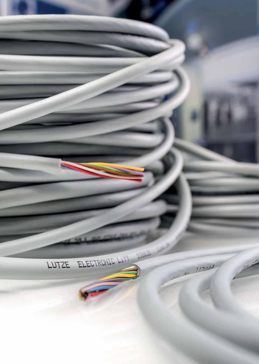
35 PVC electronic cables unshielded LÜTZE ELECTRONIC LiYY Unshielded electronic cable Application In all areas of electronics, measuring, control and regulation technologies In low voltage switchgears, communications engineering In dry and damp rooms For flexible application for free movement and without tensile loading Properties PVC Flame-retardant, self-extinguishing Resistant to most oils, greases, acids and alkalis Silicone free RoHS-compliant Technical data Voltage up to 0.34 mm V from 1,5 mm V Test voltage up to 0.34 mm V after 0.5 mm V Insulation resistance min. 20 M km Operating capacitance approx pf/m Temperature range moving -5 C to +70 C fixed -30 C to +70 C Minimum bending radius moving D 12 fixed D 4 Burning behavior Flame-retardant according to VDE 0482 part 265-2, DIN EN , IEC Construction Bare copper wire, finely stranded according to DIN VDE 0295 class 5, IEC class 5 (*exception: 0.34 mm 2 = ) Conductor insulation Special PVC Conductors color-coded according to DIN Conductors cabled in layers Jacket special PVC TM2 according to VDE , matte, adhesion-free surface Jacket color grey RAL 7001 Part-No. Number of conductors/cross-section Outer ca. mm Weight kg/100 m Cu-Index kg/100 m 0.14 mm mm mm 2 * mm CE These products are in conformity with the EU Low Voltage Directive 2006/95/EC 2.3
36 PVC electronic cables shielded LÜTZE ELECTRONIC LiY (C) Y Shielded electronic cable Application For interference-free transmission in all areas of electronics, measuring, control and regulation technology In low voltage switchgears and communications engineering In dry and damp rooms For flexible application for free movement and without tensile loading Properties PVC Flame-retardant, self-extinguishing High active and passive interference resistance (EMC) Resistant to most acids and alkalis Silicone free RoHS-compliant Technical data Voltage up to 0.34 mm V from 1,5 mm V Test voltage up to 0.34 mm V after 0.5 mm V Insulation resistance min. 20 M km Operating capacitance approx pf/m Temperature range moving -5 C to +70 C fixed -30 C to +70 C Minimum bending radius moving D 15 fixed D 6 Burning behavior Flame-retardant according to VDE 0482 part 265-2, DIN EN , IEC Construction Bare copper wire, finely stranded according to DIN VDE 0295 class 5, IEC class 5 (*exception: 0.34 mm 2 = ) Conductor insulation Special PVC Conductors color-coded according to DIN Conductors cabled in layers, foil tape Braid from tinned copper wire, optical coverage 80 % Jacket special PVC TM2 according to VDE , matte, adhesion-free surface Jacket color grey RAL 7001 Part-No. Number of conductors/cross-section Outer ca. mm Weight kg/100 m Cu-Index kg/100 m 0.14 mm (2 0.14) (3 0.14) (4 0.14) (5 0.14) (6 0.14) (7 0.14) (8 0.14) ( ) ( ) ( ) ( ) ( ) ( ) mm (2 0.25) (3 0.25) (4 0.25) (5 0.25) (6 0.25) (7 0.25) (8 0.25) ( ) ( ) ( ) ( ) ( ) ( ) ( ) mm 2 * (2 0.34) (3 0.34) (4 0.34) (5 0.34) (6 0.34) (7 0.34) (8 0.34) ( ) ( ) ( ) ( ) ( ) ( ) mm (2 0.5) (3 0.5) (4 0.5) (5 0.5) (7 0.5) (8 0.5) (10 0.5) (12 0.5) (18 0.5) (25 0.5) CE These products are in conformity with the EU Low Voltage Directive 2006/95/EC 2.4
37 PVC electronic cables shielded LÜTZE ELECTRONIC LiY (C) Y TP Shielded electronic cable, paired Application For interference-free transmission in all areas of electronics, measuring, monitoring and control technology In low voltage switchgear, communications engineering In dry and damp rooms For flexible use with free movement without tensile load Properties PVC Flame-retardant, self-extinguishing High active and passive interference resistance (EMC) High crosstalk attenuation due to twisted pairs Resistant to most oils, greases, acids and alkalis Silicone free RoHS-compliant Technical data Voltage up to 0.34 mm V from 1,5 mm V Test voltage up to 0.34 mm V after 0.5 mm V Insulation resistance min. 20 M km Operating capacitance approx pf/m Temperature range moving -5 C to +70 C fixed -30 C to +70 C Minimum bending radius moving D 15 fixed D 6 Burning behavior Flame-retardant according to VDE 0482 part 265-2;DIN EN ; IEC Construction Bare copper wire, finely stranded according to DIN VDE 0295 class 5, IEC class 5 (*exception: 0.34 mm 2 = ) Conductor insulation Special PVC Conductors color-coded according to DIN Conductors stranded pairs, foil tape Braid from tinned copper wire, optical coverage 80 % Jacket special PVC TM2 according to VDE , matte, adhesion-free surface Jacket color grey RAL 7032 Part-No. Number of conductors/cross-section Outer ca. mm Weight kg/100 m Cu-Index kg/100 m 0.14 mm ( ) ( ) ( ) ( ) ( ) ( ) ( ) ( ) ( ) mm ( ) ( ) ( ) ( ) ( ) ( ) ( ) ( ) ( ) mm 2 * ( ) ( ) ( ) ( ) ( ) ( ) ( ) mm ( ) ( ) ( ) ( ) ( ) ( ) ( ) ( ) ( ) CE These products are in conformity with the EU Low Voltage Directive 2006/95/EC 2.5
38 PVC electronic cables unshielded LÜTZE ELECTRONIC LiYY Unshielded electronic cable UL recognized Application In all areas of electronics, measuring, monitoring and regulation technologies In low voltage switchgears, communications engineering In dry and damp rooms For flexible application for free movement and without tensile loading Properties Minimal cable diameter due to thin-walled PVC conductor insulation according to UL Outer jacket special-pvc Class 43 according to UL Very good oil resistance Resistant to most acids and alkalis (see tech. information) Silicone free RoHS-compliant Technical data UL approval AWM 2464 Nominal voltage 300 V 80 C Test voltage 2000 V Insulation resistance min. 20 M km Temperature range moving -10 C to +70 C fixed -40 C to +80 C Minimum bending radius moving D 12 fixed D 4 Burning behavior Flame-retardant according to VDE 0482 part 265-2, DIN EN , IEC , UL 1581 section VW-1 Flame-Test, CSA FT 1 Construction Bare copper wire, finely stranded according to DIN VDE 0295 class 5, IEC class 5 (*exception: 0.34 mm 2 = ) Conductor insulation Special PVC Conductors color-coded according to DIN Conductors cabled in layers Jacket special-pvc Jacket color grey RAL 7001 CE These products are in conformity with the EU Low Voltage Directive 2006/95/EC Part-No. Number of conductors/cross-section Outer ca. mm Weight kg/100 m Cu-Index kg/100 m 0.14 mm mm mm 2 * mm mm
39 PVC electronic cables shielded LÜTZE ELECTRONIC LiY (C) Y Shielded electronic cable UL recognized Application For interference-free transmission in all areas of electronics, measuring, monitoring and regulation technology In low voltage switchgears, communications engineering In dry and damp rooms For flexible application for free movement and without tensile loading Especially for industrial environments with high interference potential in machine, plant and device construction Properties Minimal cable diameter due to thin-walled PVC conductor insulation according to UL High active and passive interference resistance Outer jacket special-pvc Class 43 according to UL Very good oil resistance Resistant to most acids and alkalis (see tech. information) Silicone free RoHS-compliant Technical data UL approval AWM 2464 Nominal voltage 300 V 80 C Test voltage 2000 V Insulation resistance min. 20 M km Operating capacitance approx pf/m Temperature range moving -10 C to +70 C fixed -40 C to +80 C Minimum bending radius moving D 15 fixed D 6 Burning behavior Flame-retardant according to VDE 0482 part 265-2, DIN EN , IEC , UL 1581 section VW-1 Flame-Test, CSA FT 1 Construction Bare copper wire, finely stranded according to DIN VDE 0295 class 5, IEC class 5 (*exception: 0.34 mm 2 = ) Conductor insulation Special PVC Conductors color-coded according to DIN Conductors cabled in layers Braid from tinned copper wire, optical coverage 85 % Jacket special-pvc Jacket color grey RAL 7001 CE These products are in conformity with the EU Low Voltage Directive 2006/95/EC Part-No. Number of conductors/cross-section Outer ca. mm Weight kg/100 m Cu-Index kg/100 m 0.14 mm (2 0.14) (3 0.14) (4 0.14) (5 0.14) (6 0.14) (8 0.14) ( ) ( ) ( ) ( ) ( ) mm (2 0.25) (3 0.25) (4 0.25) (5 0.25) (6 0.25) (8 0.25) ( ) ( ) ( ) ( ) ( ) mm 2 * (2 0.34) (3 0.34) (4 0.34) (5 0.34) (6 0.34) (8 0.34) ( ) ( ) ( ) ( ) ( ) mm (2 0.5) (3 0.5) (4 0.5) (5 0.5) (6 0.5) (8 0.5) (10 0.5) (12 0.5) (16 0.5) (18 0.5) (25 0.5) mm (2 0.75) (3 0.75) (4 0.75) (5 0.75) (6 0.75) (8 0.75) ( ) ( ) ( ) ( ) ( )
40 PVC electronic cables shielded LÜTZE ELECTRONIC LiY (C) Y TP Shielded electronic cable UL recognized, paired Application For interference-free transmission in all areas of electronics, measuring, monitoring and regulation technology In low voltage switchgears, communications engineering In dry and damp rooms For flexible application for free movement and without tensile loading Especially for industrial environments with high interference potential in machine, plant and device construction Properties Minimal cable diameter due to thin-walled PVC conductor insulation according to UL High active and passive interference resistance Outer jacket special-pvc Class 43 according to UL Very good oil resistance Resistant to most acids and alkalis (see tech. information) Silicone free RoHS-compliant Technical data UL approval AWM 2464 Nominal voltage 300 V 80 C Test voltage 2000 V Insulation resistance min. 20 M km Operating capacitance approx pf/m Temperature range moving -10 C to +70 C fixed -40 C to +80 C Minimum bending radius moving D 15 fixed D 6 Burning behavior Flame-retardant according to VDE 0482 part 265-2, DIN EN , IEC , UL 1581 section VW-1 Flame-Test, CSA FT 1 Part-No. Number of conductors/cross-section Outer ca. mm Weight kg/100 m Cu-Index kg/100 m 0.25 mm (2x2 0.25) (4x2 0.25) (5x2 0.25) (6x2 0.25) (8x2 0.25) mm 2 * (2x2 0.34) (4x2 0.34) (5x2 0.34) (6x2 0.34) (8x2 0.34) mm (2x2 0.5) (4x2 0.5) (5x2 0.5) (6x2 0.5) (8x2 0.5) mm ( ) ( ) ( ) ( ) ( ) Construction Bare copper wire, finely stranded according to DIN VDE 0295 class 5, IEC class 5 (*exception: 0.34 mm 2 = ) Conductor insulation Special PVC Conductors color-coded according to DIN Conductors paired, pairs cabled in layers Braid from tinned copper wire, optical coverage 85 % Jacket special-pvc Jacket color grey RAL 7001 CE These products are in conformity with the EU Low Voltage Directive 2006/95/EC 2.8
41 LÜTZE SUPERFLEX and LÜTZE SUPERFLEX PLUS LÜTZE SUPERFLEX sets Industry Standards: longevity, reliability, flexibility LÜTZE SUPERFLEX flexing cables are specifically designed for use in continuous motion applications such as drag chains. Find here more informations about LÜTZE SUPERFLEX
42 PUR electronic cables C-track compatible Unshielded LÜTZE SUPERFLEX TRONIC PUR Unshielded electronic cable UL recognized For highest requirements Application Robots, drag chains as well as everywhere where signals are transmitted to continuously moving system or machine parts Machine and device construction, transport and conveyor technology, heating, climate technology In dry and damp rooms As monitoring, measurement and control cable for continuous flexing applications Properties Low capacitance, very good electrical properties Flame-retardant, self-extinguishing Halogen-free, no corrosive gases Very good alternating bending strength Low adhesion, abrasion-resistant, nick-resistant, tear resistant Hydrolysis-resistant, microbe-resistant, and rot-resistant Good ruggedness and salt water resistance Excellent coolant and lubricant resistance Resistant to most oils, greases, alcohol-free benzines and kerosene Silicone free RoHS-compliant Technical data UL approval AWM Nominal voltage 300 V 80 C Test voltage 3000 V Insulation resistance min M km Temperature range moving -25 C to +80 C fixed -40 C to +80 C Minimum bending radius moving D 10 fixed D 4 Burning behavior Flame-retardant according to DIN EN , UL Horizontal Flame Test Halogen free according to EN Construction Bare copper wire, super finely stranded according to DIN VDE 0295 class 6, IEC class 6 Conductor insulation Special TPE, high glide Conductors color-coded according to DIN Conductors cabled in layers without mechanical stress, layer pitch optimised Fleece wrap over cable core Jacket special-pur, matte, adhesion-free surface Jacket color grey RAL 7001 Part-No. Number of conductors/cross-section Outer ca. mm Weight kg/100 m Cu-Index kg/100 m AWG 26 / 0,14 mm AWG 24 / 0,25 mm AWG 22 / 0,34 mm CE These products are in conformity with the EU Low Voltage Directive 2006/95/EC 2.10
43 PVC electronic cables C-track compatible Shielded LÜTZE SUPERFLEX TRONIC (C) PUR Shielded electronic cable UL recognized For highest requirements Application Robots, drag chains as well as everywhere where signals are transmitted to continuously moving system or machine parts Machine and device construction, transport and conveyor technology, heating, climate technology In dry and damp rooms As monitoring, measurement and control cable for continuous flexing applications Especially for industrial environments with high EMI potential in machine, plant and device construction Properties High active and passive interference resistance (EMC) Braided shield optimised for continuous flexing applications Low capacitance, very good electrical properties Flame-retardant, self-extinguishing Halogen-free, no corrosive gases Very good alternating bending strength Low adhesion, abrasion-resistant, nick-resistant, tear resistant Hydrolysis-resistant, microbe-resistant, and rot-resistant Good ruggedness and salt water resistance Excellent coolant and lubricant resistance Resistant to most oils, greases, alcohol-free benzines and kerosene Silicone free RoHS-compliant Technical data UL approval AWM Nominal voltage 300 V 80 C Test voltage 3000 V Insulation resistance min M km Temperature range moving -25 C to +80 C fixed -40 C to +80 C Minimum bending radius moving D 12 fixed D 6 Burning behavior Flame-retardant according to DIN EN , UL Horizontal Flame Test Halogen free according to EN Part-No. Number of conductors/cross-section Outer ca. mm Weight kg/100 m Cu-Index kg/100 m 0.14 mm (2 0.14) (3 0.14) (4 0.14) (5 0.14) (7 0.14) ( ) ( ) ( ) ( ) mm (2 0.25) (3 0.25) (4 0.25) (5 0.25) (7 0.25) ( ) ( ) ( ) ( ) mm (2 0.34) (3 0.34) (4 0.34) (5 0.34) (7 0.34) ( ) ( ) ( ) ( ) Construction Bare copper wire, super finely stranded according to DIN VDE 0295 class 6, IEC class 6 Conductor insulation Special-TPE Conductors color-coded according to DIN Conductors cabled in layers without mechanical stress, layer pitch optimised Fleece wrap over cable core Braid from tinned copper wire, optical coverage 85 % Jacket special-pur, matte, adhesion-free surface Jacket color grey RAL 7001 CE These products are in conformity with the EU Low Voltage Directive 2006/95/EC 2.11
44 PVC electronic cables C-track compatible Shielded LÜTZE SUPERFLEX TRONIC (C) PUR TP Shielded electronic cable UL recognized, paired For highest requirements Application Robots, drag chains as well as everywhere where signals are transmitted to continuously moving system or machine parts Machine and device construction, transport and conveyor technology, heating, climate technology In dry and damp rooms As monitoring, measurement and control cable for continuous flexing applications Especially for industrial environments with high EMI potential in machine, plant and device construction Properties High active and passive interference resistance (EMC) High crosstalk attenuation due to twisted pairs Braided shield optimised for continuous flexing applications Low capacitance, very good electrical properties Flame-retardant, self-extinguishing Halogen-free, no corrosive gases Very good alternating bending strength Low adhesion, abrasion-resistant, nick-resistant, tear resistant Hydrolysis-resistant, microbe-resistant, and rot-resistant Good ruggedness and salt water resistance Excellent coolant and lubricant resistance Resistant to most oils, greases, alcohol-free benzines and kerosene Silicone free RoHS-compliant Technical data UL approval AWM Nominal voltage 300 V 80 C Test voltage 3000 V Insulation resistance min M km Temperature range moving -25 C to +80 C fixed -40 C to +80 C Minimum bending radius moving D 12 fixed D 6 Burning behavior Flame-retardant according to VDE 0482 Part DIN EN , IEC , UL 1581 Cable Flame, FT1 Halogen free according to EN Part-No. Number of conductors/cross-section Outer ca. mm Weight kg/100 m Cu-Index kg/100 m 0.25 mm ( ) ( ) ( ) ( ) ( ) ( ) ( ) ( ) mm ( ) ( ) ( ) ( ) ( ) ( ) ( ) ( ) mm ( ) ( ) ( ) ( ) ( ) ( ) ( ) ( ) mm ( ) ( ) ( ) ( ) ( ) ( ) Construction Bare copper wire, super finely stranded according to DIN VDE 0295 class 6, IEC class 6 Conductor insulation Special-TPE Conductors color-coded according to DIN Zero-potential paired stranding, layer pitch optimised Fleece wrap over cable core Braid from tinned copper wire, optical coverage 85 % Jacket special-pur, matte, adhesion-free surface Jacket color grey RAL 7001 CE These products are in conformity with the EU Low Voltage Directive 2006/95/EC 2.12

45 3. Actuator sensor cables
46 3. Actuator sensor cables Jacket Shielding Approval Application LÜTZE SUPERFLEX PUR CE, UL Actuator sensor wiring 3.3 TRONIC AS PUR Continuous flexing applications such as c-tracks LÜTZE SUPERFLEX PUR CE UL Actuator sensor wiring 3.4 TRONIC AS (C) PUR Continuous flexing applications such as c-tracks 3.2
47 PUR actuator-sensor cables c-track suitable LÜTZE SUPERFLEX TRONIC AS PUR, unshielded For highest requirements Application Connecting cable for the actuator-sensor technology For continuous flexible use e.g. in c-tracks or free movement in the automation technology, transport and conveyor technology, machine tool manufacture PUR jacket optimally suited for rough operating conditions and aggressive coolants and lubricants Properties Very good alternating bending strength Good pressure and roll-over resistance Low adhesion, abrasion-resistant, nick-resistant, tear resistant Hydrolysis-resistant, microbe-resistant, and rot-resistant Weatherproof, ozone and UV resistant (normal lighting conditions) Good ruggedness and salt water resistance Excellent coolant and lubricant resistance Resistant to most oils, greases, alcohol-free benzines and kerosene Silicone free Halogen free RoHS-compliant Technical data UL approval AWM Nominal voltage 300 V 80 C Test voltage 3000 V Insulation resistance min. 100 M km Temperature range moving -20 C to +80 C fixed -40 C to +80 C Minimum bending radius moving D 8 fixed D 4 Burning behavior Flame retardant according to DIN EN , UL Horizontal Flame-Test, CSA FT 2 Halogen free according to EN Part-No. Number of strands/cross-section/ strand colors 0.25 mm brown, blue, black white, brown, blue, black Outer ca. mm Weight kg/100 m white, brown, green, yellow, grey, pink, blue, red 0.34 mm brown, blue, black white, brown, blue, black brown, white, blue, black, grey brown, white, blue, black, greenyellow Actuator-sensor connecting cables G : brown, blue, greenyellow 0.34: white, black, green, yellow, grey, pink, violet, red G : brown, blue, greenyellow 0.34: white, green, yellow, grey, pink, red, black, violet, greypink, redblue, whitegreen, browngreen, whiteyellow, yellowbrown, whitegrey, greybrown Cu-Index kg/100 m Construction Bare copper wire, super finely stranded according to DIN VDE 0295 class 6, IEC class 6 Conductor insulation Special-TPE Conductors color-coded based on EN Conductors cabled in layers without mechanical stress, layer pitch optimised Jacket special-pur, matte, adhesion-free surface Jacket color black RAL 9005 CE These products are in conformity with the EU Low Voltage Directive 2006/95/EC 3.3
48 PUR actuator-sensor cables C-track suitable LÜTZE SUPERFLEX TRONIC AS (C) PUR, shielded For highest requirements Application Connecting cable for the actuator-sensor technology For continuous flexible use e.g. in c-tracks or free movement in the automation technology, transport and conveyor technology, machine tool manufacture PUR jacket optimally suited for rough operating conditions and aggressive coolants and lubricants Properties Very good alternating bending strength High active and passive interference resistance (EMC) Good pressure and roll-over resistance Low adhesion, abrasion-resistant, nick-resistant, tear-propagation-resistant Hydrolysis-resistant, microbe-resistant, and rot-resistant Weatherproof, ozone and UV resistant (normal lighting conditions) Good resistance to use and salt water Excellent coolant and lubricant resistance Resistant to most oils, greases, alcohol-free benzines and kerosene Silicone free Halogen free RoHS compliant Technical data UL approval AWM Nominal voltage 300 V 80 C Test voltage 3000 V Insulation resistance min. 100 M km Temperature range moving -20 C to +80 C fixed -40 C to +80 C Minimum bending radius moving D 12 fixed D 6 Burning behavior Flame retardant according to DIN EN , UL Horizontal Flame-Test, CSA FT 2 Halogen free according to EN Part-No. Number of strands/cross-section/ strand colors 0.25 mm (3 0.25) brown, blue, black (4 0.25) white, brown, blue, black Outer ca. mm Weight kg/100 m (8 0.25) white, brown, green, yellow, grey, pink, blue, red 0.34 mm (3 0.34) brown, blue, black (4 0.34) white, brown, blue, black (5 0.34) brown, white, blue, black, grey Cu-Index kg/100 m Construction Bare copper wire, super finely stranded according to DIN VDE 0295 class 6, IEC class 6 Conductor insulation Special-TPE Conductors color-coded based on EN Conductors cabled in layers without mechanical stress, layer pitch optimised Fleece wrap over cable core Braid from tinned copper wire, optical coverage 85 % Jacket special-pur, matte, adhesion-free surface Jacket color black RAL 9005 CE These products are in conformity with the EU Low Voltage Directive 2006/95/EC 3.4

49 4. Bus and network cables
50 4. Bus and network cables Jacket Shielding Approval Application LÜTZE ELECTRONIC TPE CE For Stationary and Flexible Applications within 4.3 ASI BUS TPE Machine- and Plant Wiring According to ASI BUS standard LÜTZE ELECTRONIC PVC CE For Stationary and Flexible Applications within 4.4 Profibus (C) PVC Machine- and Plant Wiring According to Profibus standard LÜTZE ELECTRONIC PVC CE For Stationary and Flexible Applications within 4.5 Profibus (C) PVC Machine- and Plant Wiring According to Profibus standard LÜTZE SUPERFLEX PUR CE, UL Continuous Moving in Drag Chains 4.6 Profibus (C) PUR According to Profibus standard with international approvals For highest requirements LÜTZE ELECTRONIC PVC CE, UL For Stationary and Flexible Applications within 4.7 CAN-BUS (C) PVC Machine- and Plant Wiring According to CAN-BUS standard with international approvals LÜTZE SUPERFLEX PUR CE, UL Continuous Moving in Drag Chains 4.8 CAN-BUS (C) PUR According to CAN-BUS standard with international approvals For extremely harsh operating conditions LÜTZE ELECTRONIC PVC CE, UL For Stationary and Flexible Applications within 4.9 INTERBUS (C) PVC Machine- and Plant Wiring According to INTERBUS standard with International approvals LÜTZE SUPERFLEX PUR CE, UL Continuous Moving in Drag Chains 4.10 INTERBUS (C) PUR According to INTERBUS standard with international approvals For extremely harsh operating conditions LÜTZE ELECTRONIC PVC CE, UL For Stationary and Flexible Applications within 4.11 DeviceNet TM (C) PVC Machine- and Plant Wiring According to DeviceNet TM standard with International approvals LÜTZE SUPERFLEX PUR CE, UL Continuous Moving in Drag Chains 4.12 DeviceNet TM (C) PUR According to DeviceNet TM standard with international approvals For extremely harsh operating conditions LÜTZE ELECTRONIC PVC CE, UL, AWM For Stationary and Flexible Applications within 4.13 ETHERNET (C) PVC Machine- and Plant Wiring Industrial Ethernet/Profinet/EtherCat Industrial Ethernet/Ethernet IP Cat 5e, Cat 6a, Cat 7 LÜTZE SUPERFLEX PUR CE, UL, AWM Continuous Moving in Drag Chains 4.14 ETHERNET (C) PUR Industrial Ethernet/Profinet/EtherCat Industrial Ethernet/Ethernet IP Cat 5e, Cat 6 For extremely harsh operating conditions * Registered Trade Marks 4.2
51 Bus cables ASI BUS LÜTZE ELECTRONIC ASI BUS TPE Application System cables for connection of actuator interface components Application in the automation technology, in tool and machine construction, plants and device construction, transport and conveyor technology Properties Inverse polarity-proof flat cable Fast contacting due to penetration technology TPE construction especially suitable in areas in which oils, greases and cooling lubricants occur Silicone free RoHS-compliant Technical data Rated voltage 300 V Test voltage 2000 V Temperature range moving -15 C to +80 C fixed -30 C to +80 C Minimum bending radius moving D 12 fixed D 6 Loop resistance 27.4 m /m Part-No. Number of strands/cross-section/ strand colors 1.5 mm blue, brown blue, brown Weight kg/100 m Cu-Index kg/100 m Jacket yellow black Construction Tinned copper wire Braid 1.5 mm 2 according to VDE 0295 Class 6 Conductor insulation PVC Jacket TPE profiled Jacket color black RAL 9005: for auxiliary energy 30 V DC yellow RAL 1021: data and energy transfer CE These products are in conformity with the EU Low Voltage Directive 2006/95/EC 4.3
52 Bus cables Profibus LÜTZE ELECTRONIC Profibus (C) PVC Application For the cabling of industrial field bus systems like PROFIBUS DP, F.I.P. With solid conductor AWG22/1 for fixed wiring or with stranded conductor for moving applications without continuous flexing in the automation technology, transport and conveyor technology, machine tool manufacture Properties High active and passive interference resistance (EMC) Silicone free RoHS-compliant Technical data Rated voltage 250 V Test voltage 1500 V Impedance AWG 22: nom mm 2 : nom. 100 Loop resistance AWG 22: <110 /km 1.0 mm 2 : 39 /km Operating capacitance AWG 22: nom. 30 pf/m 1.0 mm 2 : nom. 52 pf/m Temperature range moving -5 C to +70 C fixed -30 C to +80 C Minimum bending radius moving D 12 fixed D 6 Burning behavior Flame-retardant according to VDE 0482 part 265-2, HM version: halogen free, low smoke Part-No. Number of strands/cross-section/ strand colors Profibus DP/FMS/FIP (1 2 AWG22/7)StC red/green Jacket color violet RAL 4001 Outer ca. mm Weight Cu-Index kg/100 m kg/100 m Profibus DP/FMS/FIP with inner jacket, halogen-free jacket (HM) (1 2 AWG22/1)StC FC red/green violet RAL Profibus PA (1 2 AWG18/1) red/green blue RAL (1 2 AWG18/1) red/green black RAL Construction Bare copper wire Wire according to AWG or DIN Conductor insulation special polyolefin ST Static foil shield Braid from tinned copper wire, optical coverage 70 % PVC jacket or HM version with special thermoplastic Jacket color violet RAL 4001, blue RAL 5015, black RAL 9005 (see item description) CE These products are in conformity with the EU Low Voltage Directive 2006/95/EC 4.4
53 PVC Bus cables Profibus LÜTZE ELECTRONIC Profibus (C) PVC Application For the cabling of industrial field bus systems like PROFIBUS DP, F.I.P. With solid conductor AWG22/1 for hard wiring or with 7-wire stranded conductor for moving use without continuous flexing in the automation technology, transport and conveyor technology, machine tool manufacture Properties High active and passive interference resistance (EMC) Silicone free RoHS-compliant Technical data Rated voltage 300 V Test voltage 1500 V Impedance nom. 150 Loop resistance Solid 22/1 <110 /km Flexible 24/7 <165 /km Operating capacitance nom. 30 pf/m Temperature range moving -10 C to +70 C fixed -40 C to +80 C Minimum bending radius moving D 15 fixed D 7.5 Burning behavior CMX: FT1 UL 1581, IEC CMG: FT4 UL 1685, CSA UL, IEC Approvals culus Part-No. Number of strands/cross-section/ strand colors Outer ca. mm Weight kg/100 m Cu-Index kg/100 m Profibus DP/FMS/FIP, single wire UL/CMX, AWM V (1 2 AWG22/1) red/green Profibus DP/FMS/FIP, Flexible UL/CMG 75 C, AWM V (1 2 AWG24/7) red/green Profibus DP/FMS/FIP, Fast Connection FC UL/CMG, AWM V (1 2 AWG22/1) red/green Construction Bare copper wire Wire according to AWG Conductor insulation Special polyolefin Inner jacket for versions with fast assembly FC ST static shield Braid shield from tinned copper, optical coverage ca. 70 %. Jacket special-pvc Jacket color violet RAL 4001 CE These products are in conformity with the EU Low Voltage Directive 2006/95/EC 4.5
54 PUR Bus cables Profibus C-track compatible LÜTZE SUPERFLEX Profibus (C) PUR For highest requirements Application For the cabling of industrial field bus systems like PROFIBUS DP, SINEC L2, F.I.P. For continuous flexible use e.g. in c-tracks or free movement in automation technology, transport and conveyor technology, machine tool manufacture Properties High active and passive interference resistance (EMC) Silicone free Halogen free RoHS-compliant Technical data Rated voltage 300 V Test voltage 1500 V Impedance nom. 150 Loop resistance <165 /km Operating capacitance <30 pf/m Temperature range moving -30 C to +70 C fixed -40 C to +80 C Minimum bending radius moving D 7.5 fixed D 5 moves quick assembly FC D 15 fixed D 7.5 Burning behavior VW-1, FT 1 UL 1581, IEC Halogen free according to EN Approvals culus CMX, UL AWM V 80 C Part-No. Number of strands/cross-section/ strand colors Profibus, high flexing UL/CMX (1 2 AWG24/19) red/green Profibus Fast Connection FC UL/CMX (1 2 AWG24/19) red/green Profibus ET200 UL AWM ((1 2 AWG24/19)St+3G0.75)C red/green, blue/black/greenyellow Outer ca. mm Weight kg/100 m Cu-Index kg/100 m Construction Bare copper wire Wire according to AWG Wire AWG 24/19 = 0.64 mm Conductor insulation special polyolefin Inner jacket versions with fast assembly FC ST foil shield Braid shield from tinned copper, optical coverage approx. 85 %, at FC 70 % Jacket special-pur, matte, adhesion-free surface Jacket color violet, RAL 4001 CE These products are in conformity with the EU Low Voltage Directive 2006/95/EC 4.6
55 PVC Bus cables CAN-BUS LÜTZE ELECTRONIC CAN-BUS (C) PVC Application For wiring of industrial field bus systems like CAN-BUS For fixed wiring or moving applications without continuous flexing in the automation technology, transport and conveyor technology, machine tool manufacture Properties High active and passive interference resistance (EMC) Silicone free RoHS-compliant Technical data Rated voltage 300 V Test voltage 1500 V Impedance nom. 120 Loop resistance AWG 24/7 <175.2 /km AWG 22/7 <110.8 /km Operating capacitance <60 pf/m Temperature range moving -10 C to +70 C fixed -40 C to +75 C Minimum bending radius moving D 15 fixed D 7.5 Burning behavior Flame-retardant according to VDE 0482 part 265-2; IEC Approvals culus CMX Part-No. Number of strands/cross-section/ strand colors CAN-BUS UL/CMX, 40 m max (1 2 AWG24/7) white/brown (2 2 AWG24/7) white/brown, green/yellow CAN-BUS UL/CMX, 200 m max (1 2 AWG22/7) white/brown (2 2 AWG22/7) white/brown, green/yellow Outer ca. mm Weight kg/100 m Cu-Index kg/100 m Construction Bare copper wire Wire according to AWG or DIN Conductor insulation Special polyolefin Conductors stranded pairs, foil tape Braid from tinned copper wire, optical coverage 85 % Jacket special PVC TM2 according to VDE , matte, adhesion-free surface Jacket color violet, RAL 4001 CE These products are in conformity with the EU Low Voltage Directive 2006/95/EC 4.7
56 PUR Bus cables CAN-BUS C-track compatible LÜTZE SUPERFLEX CAN-BUS (C) PUR For highest requirements Application For wiring of industrial field bus systems like CAN-BUS for continuous flexible use e.g. in c-tracks or free movement in the automation technology, transport and conveyor technology, machine tool manufacture Properties High active and passive interference resistance (EMC) Silicone free Halogen free RoHS-compliant Technical data Rated voltage 300 V Test voltage 3000 V Impedance nom. 120 Operating capacitance <60 pf/m Temperature range moving -30 C to +70 C fixed -40 C to +75 C Minimum bending radius moving D 15 fixed D 7.5 Burning behavior Flame-retardant according to VDE 0482 part 265-2; IEC UL 1581 section VW-1 Flame-Test, CSA FT 1 Halogen free according to EN Approvals culus CMX Part-No. Number of strands/cross-section/ strand colors CAN-BUS UL/CMX, 40 m max (1 2 AWG24) white/brown (2 2 AWG24) white/brown, green/yellow Outer ca. mm Weight kg/100 m Cu-Index kg/100 m Construction Bare copper wire Conductor insulation Special polyolefin Stranded pair conductors or star quad, foil tape Braid from tinned copper wire, optical coverage 85 % Jacket special-pur, matte, adhesion-free surface Jacket color violet RAL 4001 CE These products are in conformity with the EU Low Voltage Directive 2006/95/EC 4.8
57 PVC Bus cables INTERBUS LÜTZE ELECTRONIC INTERBUS (C) PVC Application For wiring of industrial field bus systems such as Interbus For fixed installation or moving use without continuous flexing in the automation technology, transport and conveyor technology, machine tool manufacture Properties High active and passive interference resistance (EMC) Silicone free RoHS-compliant Technical data UL approval AWM Nominal voltage 300 V 60 C Test voltage 1500 V Impedance nom. 100 Loop resistance <165 /km Operating capacitance <60 pf/m Temperature range moving -10 C to +70 C fixed -40 C to +80 C Minimum bending radius moving D 15 fixed D 7.5 Burning behavior Flame-retardant according to VDE 0482 part 265-2; IEC UL Horizontal Flame Part-No. Number of strands/cross-section/ strand colors ( ) white/brown, green/yellow, grey/pink Outer ca. mm Weight kg/100 m Cu-Index kg/100 m Construction Bare copper wire Wire according to AWG or DIN Conductor insulation Special polyolefin Conductors stranded pairs, foil tape Braid from tinned copper wire, optical coverage 85 % Jacket special PVC TM2 according to VDE , matte, adhesion-free surface Jacket color violet RAL 4001 CE These products are in conformity with the EU Low Voltage Directive 2006/95/EC 4.9
58 PUR bus cables INTERBUS C-track compatible LÜTZE SUPERFLEX INTERBUS (C) PUR Application For wiring of industrial field bus systems such as Interbus For continuous flexible use e.g. in c-tracks or free movement in the automation technology, transport and conveyor technology, machine tool manufacture Properties High active and passive interference resistance (EMC) Silicone free Halogen free RoHS-compliant Technical data UL approval AWM Nominal voltage 300 V 80 C Test voltage 3000 V Impedance nom. 100 Loop resistance <155 /km Operating capacitance <60 pf/m Temperature range moving -20 C to +80 C fixed -40 C to +80 C Minimum bending radius moving D 12 fixed D 6 Burning behavior Flame-retardant according to VDE 0482 part 265-2; IEC UL 1581 section VW-1 Flame-Test, CSA FT 1 Halogen free according to EN Part-No. Number of strands/cross-section/ strand colors ( ) white/brown; green/yellow; grey/pink (3G ) white/brown; green/yellow; grey/pink Outer ca. mm Weight kg/100 m Cu-Index kg/100 m Construction Bare copper wire Wire according to AWG or DIN Conductor insulation Special polyolefin Conductors stranded pairs, foil tape Braid from tinned copper wire, optical coverage 85 % Jacket special-pur, matte, adhesion-free surface Jacket color violet RAL 4001 CE These products are in conformity with the EU Low Voltage Directive 2006/95/EC 4.10
59 PVC bus cables DeviceNet TM LÜTZE ELECTRONIC DeviceNet TM (C) PVC Application For the wiring of industrial devices, sensors, control devices (SPS), valves DeviceNet TM is the leading BUS system for industry automation in the USA For fixed wiring or moving applications without continuous flexing in the automation technology, transport and conveyor technology, machine tool manufacture Properties High active and passive interference resistance (EMC) Silicone free RoHS compliant Technical data Rated voltage 300 V Test voltage 2000 V Impedance nom. 120 Loop resistance AWG 16 <22.6 /km AWG 18 <54.4 /km AWG 22 <114.8 /km AWG 24 <181.8 /km Operating capacitance <40 pf/m Temperature range moving -10 C to +75 C fixed -40 C to +75 C Minimum bending radius moving D 10 fixed D 5 Burning behavior Flame-retardant according to VDE 0482 part 265-2, IEC UL 1581 section VW-1 Flame-Test, CSA FT 4 Approvals culus CMG UL AWM V 60 C Part-No. Number of strands/cross-section/ strand colors DeviceNet TM Thick UL/CMG, PLTC ((2xAWG18)+(2xAWG16)) white/blue, red/black DeviceNet TM Thin UL/CMG/CL ((2xAWG24)+(2xAWG22)) white/blue, red/black Outer ca. mm Weight kg/100 m Cu-Index kg/100 m Construction Tinned copper wire Conductor insulation Special polyolefin (BUS element) Overall shield: Braid from galvanised Cu wire, optical coverage 70 % Jacket special-pvc, matte, adhesion-free surface Jacket color violet RAL 4001 CE These products are in conformity with the EU Low Voltage Directive 2006/95/EC 4.11
60 PUR Bus cables DeviceNet TM C-track compatible LÜTZE SUPERFLEX DeviceNet TM (C) PUR For highest requirements Application For the wiring of industrial devices, sensors, control devices (SPS), valves DeviceNet TM is the leading BUS system for industry automation in the USA For continuous flexible use e.g. in c-tracks or free movement in the automation technology, transport and conveyor technology, machine tool manufacture Properties High active and passive interference resistance (EMC) Silicone free RoHS compliant Technical data Impedance nom. 120 Operating capacitance <40 pf/m Rated voltage 300 V Test voltage 3000 V Temperature range moving -20 C to +80 C fixed -40 C to +75 C Minimum bending radius moving D 10 fixed D 5 Burning behavior Flame-retardant according to VDE 0482 part 265-2; IEC ; UL 1581 section VW-1 Flame-Test; CSA FT 1 Halogen free according to EN , EN Approvals culus CMX Part-No. Number of strands/cross-section/ strand colors DeviceNet TM Thick UL/CMX ((2 AWG18)+(2 AWG16)) white/blue, red/black DeviceNet TM Thin UL/CMX ((2 AWG24)+(2 AWG22)) white/blue, red/black Outer ca. mm Weight kg/100 m Cu-Index kg/100 m Construction Tinned copper wire Special polyolefin (BUS element) BUS element statically shielded Total shield: Braid from galvanised Cu wire, optical coverage 85 % Jacket special-pur, matte, adhesion-free surface Jacket color violet RAL 4001 CE These products are in conformity with the EU Low Voltage Directive 2006/95/EC 4.12
61 PVC Bus cables ETHERNET LÜTZE ELECTRONIC ETHERNET (C) PVC Application For the cabling of industrial field bus systems with the globally accepted TCP/IP protocol For fixed installation or mobile use without continuous flexing in automation technology, transport, conveyor technology and machine tools Properties High active and passive interference resistance (EMC) Silicone free RoHS-compliant Technical data Rated voltage 300 V Test voltage 1500 V Impedance nom. 100 Loop resistance Wire AWG 22/1= Wire AWG 24/7= Wire AWG 26/7= Operating capacitance <110 /km <165 /km <273 /km <50 pf/m Temperature range moving -5 C to +70 C run -30 C to +80 C Minimum bending radius moving D 12 fixed D 6 Burning behavior Flame-retardant according to VDE 0482 part 265-2; IEC UL 1581 section VW-1 Flame-Test, CSA FT 4 Approvals culus CMG culus PLTC curus AWM Construction Bare copper wire Wire according to AWG Conductor insulation Special polyolefin ST static shield Braid from tinned copper wire, optical coverage 85 % Jacket PVC, matte, adhesion-free surface Jacket color green RAL 6018 Part-No. Number of strands/cross-section/ strand colors Outer ca. mm Weight kg/100 m Cu-Index kg/100 m ELECTRONIC Industrial Ethernet/Profinet/EtherCat (2x2 AWG22/1)StC CMG, PLTC, AWM V Cat5 100 MHz, SF/UTQ Star quad, FC, ProfiNet type A Transmission pair white/blue, yellow/ orange (2x2xAWG22/7)StC CMG, PLTC, AWM V Cat5 100 MHz, SF/UTQ Star quad, FC, ProfiNet type B Transmission pair white/blue, yellow/ orange (4 (2 AWG22/1)St)C CMG, PLTC, AWM V Cat6a 600 MHz, S/FTP whiteblue/blue, whiteorange/orange, whitegreen/green, whitebrown/brown ELECTRONIC Industrial Ethernet/Ethernet IP (4x2xAWG26/7 StC) CMG Cat5e 100 MHZ, SF/UTP whiteblue/blue, whiteorange/orange, whitegreen/green, whitebrown/brown (4x2xAWG24/7 StC) CMG Cat5e 100 MHZ, SF/UTP whiteblue/blue, whiteorange/orange, whitegreen/green, whitebrown/brown (4x(2xAWG26/7)St)C CMG Cat6a 500 MHZ, S/FTP whiteblue/blue, whiteorange/orange, whitegreen/green, whitebrown/brown (4x(2xAWG26/7)St)C CMG Cat7 600 MHZ, S/FTP whiteblue/blue, whiteorange/orange, whitegreen/green, whitebrown/brown CE These products are in conformity with the EU Low Voltage Directive 2006/95/EC 4.13
62 PUR Bus cables ETHERNET C-track compatible LÜTZE SUPERFLEX ETHERNET (C) PUR For highest requirements Application For the cabling of industrial field bus systems with the globally accepted TCP/IP protocol For fixed installation or mobile use without continuous flexing in automation technology, transport, conveyor technology and machine tools Properties High active and passive interference resistance (EMC) Silicone free Halogen free RoHS-compliant Technical data Rated voltage 250 V Test voltage 1500 V Impedance nom. 100 Loop resistance AWG 22/7= AWG 22/19= AWG 24/19= AWG 26/19= Operating capacitance <110 /km <110 /km <159,5 /km <280 /km <50 pf/m Temperature range moving -30 C to +70 C fixed -40 C to +80 C Minimum bending radius moving D 12 fixed D 6 Burning behavior Flame-retardant according to VDE 0482 part 265-2; IEC , UL 1581 section VW-1 Flame-Test, CSA FT 1 Halogen free according to EN Approvals culus CMX curus AWM Part-No. Number of strands/cross-section/ strand colors Outer ca. mm Weight kg/100 m Cu-Index kg/100 m SUPERFLEX Industrial Ethernet/ProfiNet/Ethercat (2 2 AWG22/19)StC CMX Cat5 100 MHZ, SF/UTQ Star quad Transmission pair white/blue, yellow/ orange (2 2 AWG22/7)StC CMX Cat5 100 MHZ, SF/UTQ Star quad, Profinet type C Transmission pair white/blue, yellow/ orange SUPERFLEX Industrial Ethernet/Ethernet IP (2 2 AWG26/19) AWM Cat5e 100 MHz, SF/UTQ white, blue, yellow, orange (4 2 AWG24/19) AWM Cat5e 100 MHz, S/UTP whiteblue/blue, whiteorange/orange, whitegreen/green, whitebrown/brown (4 2 AWG26/19) AWM Cat5e 100 MHz, SF/UTP whiteblue/blue, whiteorange/orange, whitegreen/green, whitebrown/brown (4 2 AWG26/19) CMX Cat6 350 MHZ, SF/UTP whiteblue/blue, whiteorange/orange, whitegreen/green, whitebrown/brown Construction Bare copper wire Wire according to AWG Conductor insulation Special polyolefin ST static shield Halogen-free sub jacket Braid from tinned copper wire, optical coverage 85 % Jacket special-pur, matte, adhesion-free surface Jacket color green RAL 6018 CE These products are in conformity with the EU Low Voltage Directive 2006/95/EC 4.14

63 5. Motor, Servo and Feedback cables
64 5. Motor, Servo and Feedback cables Jacket Shielding Approval Application LÜTZE SILFLEX PVC CE For Stationary and Flexible Applications within 5.3 M PVC 0,6/1 kv Machine- and Plant Wiring LÜTZE SILFLEX PVC CE For Stationary and Flexible Applications within 5.4 M (C) PVC 0,6/1 kv Machine- and Plant Wiring LÜTZE SILFLEX PVC CE For Stationary and Flexible Applications within 5.5 M XLPE 3 (C) PVC 0,6/1 kv Machine- and Plant Wiring LÜTZE-SILFLEX PVC CE, UL For Stationary and Flexible Applications within 5.6 M (C) PVC UL SERVO 0,6/1 kv Machine- and Plant Wiring with international Approval LÜTZE-SILFLEX PVC CE, UL For Stationary and Flexible Applications within 5.7 (C) PVC FEEDBACK Machine- and Plant Wiring with international Approval LÜTZE SUPERFLEX PUR CE, UL Continuous Moving in Drag Chains 5.9 PLUS M PUR UL 0,6/1 kv Motor- / Power Supply Cable For highest requirements LÜTZE SUPERFLEX PUR CE, UL Continuous Moving in Drag Chains 5.10 PLUS M (C) PUR UL SERVO 0,6/1 kv Supply line for Siemens* and other systems For highest requirements LÜTZE SUPERFLEX PUR CE, UL Continuous Moving in Drag Chains 5.11 PLUS M (C) PUR SERVO 0,6/1 kv Supply line for Bosch-Rexroth* and other systems For highest requirements LÜTZE SUPERFLEX PUR CE, UL Continuous Moving in Drag Chains 5.12 PLUS M (C) PUR SERVO 0,6/1 kv Supply line for Lenze* and other systems For highest requirements LÜTZE SUPERFLEX PUR CE, UL Continuous Moving in Drag Chains 5.13 PLUS M (C) PUR SERVO 0,6/1 kv Supply line for SEW* and other systems For highest requirements LÜTZE SUPERFLEX PUR CE, UL Continuous Moving in Drag Chains 5.14 PLUS (C) PUR HYBRID SERVO 0,6/1kV Composite Supply Cable for Servo Motors with Hiperface DSL interface For highest requirements LÜTZE SUPERFLEX PUR CE, UL Continuous Moving in Drag Chains 5.15 PLUS PUR 0,6/1kV Motor- / Power Supply Cable For highest requirements LÜTZE SUPERFLEX PUR CE, UL Continuous Moving in Drag Chains 5.16 PLUS (C) PUR 0,6/1kV Motor- / Power Supply Cable For highest requirements LÜTZE SUPERFLEX PUR CE, UL Continuous Moving in Drag Chains 5.17 PLUS (C) PUR FEEDBACK Feedback cables for Siemens* and other systems For highest requirements in Drive Technology LÜTZE SUPERFLEX PUR CE, UL Continuous Moving in Drag Chains 5.18 PLUS (C) PUR FEEDBACK Feedback cables for Bosch-Rexroth* and other systems For highest requirements in Drive Technology LÜTZE SUPERFLEX PUR CE, UL Continuous Moving in Drag Chains 5.19 PLUS (C) PUR FEEDBACK Feedback cables for Lenze* and other systems For highest requirements in Drive Technology LÜTZE SUPERFLEX PUR CE, UL Continuous Moving in Drag Chains 5.20 PLUS (C) PUR FEEDBACK Feedback cables for SEW* and other systems For highest requirements in Drive Technology LÜTZE SUPERFLEX PUR CE, UL Continuous Moving in Drag Chains 5.21 PLUS (C) PUR FEEDBACK Feedback cables for Allen Bradley* and other systems For highest requirements in Drive Technology LÜTZE SUPERFLEX PUR CE, UL Continuous Moving in Drag Chains 5.22 PLUS (C) PUR FEEDBACK Feedback cables for Heidenhain* and other systems For highest requirements in Drive Technology LÜTZE SUPERFLEX PUR CE, UL Continuous Moving in Drag Chains 5.23 PLUS (C) PUR FEEDBACK Feedback Cables for Various Systems For highest requirements in Drive Technology * Registered Trade Marks 5.2
65 PVC motor cables unshielded LÜTZE SILFLEX M PVC 0,6/1 kv Motor/connecting/power supply cable Application Motor/connecting and power supply cable in machine engineering, transport and conveyor technology, HVAC technology In dry and damp rooms For flexible application without continuous flexing Properties PVC Flame-retardant, self-extinguishing Resistant to most oils, greases, acids and bases Silicone free RoHS compliant Technical data Voltage U 0 /U 0.6/1 kv Test voltage 4000 V Insulation resistance min. 20 M km Temperature range moving -5 C to +70 C fixed -25 C to +70 C Minimum bending radius moving D 10 fixed D 4 Burning behavior Flame-retardant according to VDE 0482 part 265-2, DIN EN IEC Part-No. Number of conductors/cross-section Outer ca. mm Weight kg/100 m Cu-Index kg/100 m G G G G G G G G G G G G G Construction Bare copper wire, super finely stranded according to DIN VDE 0295 Kl. 5 or IEC cl. 5 Conductor insulation Special PVC Conductors black with white number print according to DIN EN Ground conductor green/yellow according to DIN EN Jacket special PVC TM5 according to VDE , matte, adhesion-free surface Jacket color black RAL 9005 CE These products are in conformity with the EU Low Voltage Directive 2006/95/EC 5.3
66 PVC motor cables shielded LÜTZE SILFLEX M (C) PVC 0,6/1 kv Shielded motor/connecting/power supply cable Application Motor/connecting and power supply cable in machine engineering, transport and conveyor technology, HVAC technology In dry and damp rooms Cables with integrated, shielded measurement circuit cable for motor protector devices For flexible application without continuous flexing Properties High active and passive interference resistance (EMC) PVC Flame-retardant, self-extinguishing Resistant to most oils, greases, acids and bases Silicone free RoHS compliant Technical data Voltage U 0 /U 0.6/1 kv Test voltage 4000 V Insulation resistance min. 20 M km Temperature range moving -5 C to +70 C fixed -40 C to +80 C Minimum bending radius moving D 15 fixed D 4 Burning behavior Flame-retardant according to VDE 0482 part 265-2, DIN EN , IEC Part-No. Number of conductors/cross-section Outer ca. mm Weight kg/100 m Cu-Index kg/100 m (4G1.5) (4G2.5) (4G4) (4G6) (4G10) (4G16) (4G25) (4G35) Construction Bare copper wire, super finely stranded according to DIN VDE 0295 Kl. 5 or IEC cl. 5 Special PVC Conductors black with white number print according to DIN EN Ground conductor green/yellow according to DIN EN Inner jacket special PVC Braid from tinned copper wire, optical coverage 85 % Jacket special PVC according to VDE , matte, adhesionfree surface Jacket color black RAL 9005 CE These products are in conformity with the EU Low Voltage Directive 2006/95/EC 5.4
67 PVC motor and frequency converter cables shielded LÜTZE SILFLEX M XLPE 3 (C) PVC 0,6/1 kv 2XSL(ST)CY-JB motor connecting cable for frequency converter Application Flexible motor supply cable in machine and device construction, transport and conveyor technology, HVAC technology In dry and damp rooms For flexible applications without continuous flexing Easy installation and cable routing Low capacitance for long cable guide Low-loss power transmission Properties Protective conductor divided by three for improved symmetry and reduced induction Special XLPE insulation with low capacitance Increased temperature resistance (90 C) for the conductor and jacket material High dielectric strength High current carrying capacity Specially suited to usage with frequency converters High active and passive interference resistance (EMC) PVC Flame-retardant, self-extinguishing Resistant to most oils, greases, acids and bases Silicone free RoHS compliant Technical data Voltage U 0 /U 0.6/1 kv Test voltage 4000 V Insulation resistance min. 500 M km Temperature range moving -5 C to +70 C fixed -30 C to +90 C Minimum bending radius moving fixed Burning behavior D mm D mm D 20 > 20 mm D 5 12 mm D 7,5 20 mm D 10 > 20 mm Flame-retardant and self-extinguishing according to DIN EN Part-No. Number of conductors/cross-section Outer ca. mm Weight kg/100 m Cu-Index kg/100 m ( G0.25) ( G0.5) (3 4+3G0.75) (3 6+3G1.0) (3 10+3G1.5) (3 16+3G2.5) (3 25+3G4) (3 35+3G6) (3 50+3G10) (3 70+3G10) (3 95+3G16) (3x120+3G16) Construction Bare copper wire, super finely stranded according to DIN VDE 0295 Kl. 5 or IEC cl. 5 Conductor insulation Special XLPE Conductors color-coded according to Cenelec HD 308 Ground conductor green/yellow according to DIN EN Aluminium concealed foil shield Braid from tinned copper wire, optical coverage 85 % Jacket special-pvc Jacket color black RAL 9005 CE These products are in conformity with the EU Low Voltage Directive 2006/95/EC 5.5
68 PVC servo cables shielded LÜTZE SILFLEX M (C) PVC SERVO 0.6/1 kv Motor/energy supply cable for Siemens and other systems Application For Siemens 6FX5008* standard system (and similar) Connection cable motor or motor/brake especially for frequency converters and SERVO drives in machine and plant construction, transport and conveyor technology Flexible construction for easy installation Suitable for static laying and slight movement of machine components (not C-track) Low capacitance for high dielectric strength for long cable guide from inverter to motor In dry and damp rooms Especially for industrial environments in mechanical and system engineering Properties Low capacitance for high dielectric strength High active and passive interference resistance (EMC) PVC, flame-retardant and self-extinguishing Orange RAL 2003 per DESINA Resistant to most oils, greases, alcohol-free benzines and kerosene Silicone free RoHS compliant Technical data UL approval AWM 2570 Nominal voltage 1000 V 80 C Voltage U 0 /U 0.6/1 kv Test voltage 4000 V Insulation resistance min. 500 M km Temperature range moving -5 C to +80 C fixed -25 C to +80 C Minimum bending radius moving D 10 fixed D 6 Burning behavior Flame-retardant according to VDE 0482 part 265-2, DIN EN , IEC , UL 1581 section 1080 VW-1, CSA FT 1 Part-No. Number of conductors/cross-section SIE- MENS designation Outer ca. mm Weight Cu-Index kg/100 m kg/100 m Construction without signal strands (4G1.5) 1BB11* (4G2.5) 1BB21* (4G4) 1BB31* (4G6) 1BB41* (4G10) 1BB51* (4G16) 1BB61* (4G25) 1BB25* (4G35) 1BB35* Construction with 1 signal pair (4G1.5+(2 1.5)) 1BA11* (4G2.5+(2 1.5)) 1BA21* (4G4+(2 1.5)) 1BA31* (4G6+(2 1.5)) 1BA41* (4G10+(2 1.5)) 1BA51* (4G16+(2 1.5)) 1BA61* (4G25+(2 1.5)) 1BA25* Construction Bare copper wire, super finely stranded according to DIN VDE 0295 Kl. 5 or IEC cl. 5 Conductor insulation Special TPM/PP Conductor marking Power conductors black with number print U/ L1/C/L+, V/L2, W/L3/D/L- Ground conductor green/yellow according to DIN EN in the top layer G = with green/yellow ground conductor, = without ground conductor Signal strands: white/black (1 pair) Fleece wrap over cable core Braid from tinned copper wire, optical coverage 85 % Jacket special-pvc, matte, adhesion-free surface Jacket color orange RAL 2003 CE These products are in conformity with the EU Low Voltage Directive 2006/95/EC *Siemens article designations are registered trademarks of Siemens AG 5.6
69 PVC feedback cables shielded LÜTZE SILFLEX (C) PVC FEEDBACK Feedback cable for Siemens DRIVE-CLIQ 6FX5008 standard system Application Digital feedback cable compatible with Siemens DRIVE-CLIQ standard stystem In dry and damp rooms For flexible applications without continuous flexing Properties High active and passive interference resistance (EMC) PVC Flame-retardant, self-extinguishing Resistant to most oils, greases, acids and bases Silicone free RoHS compliant Technical data UL approval AWM 2502 Nominal voltage 30 V 80 C Test voltage 500 V Insulation resistance min. 20 M km Temperature range moving -5 C to +80 C fixed -25 C to +80 C Minimum bending radius moving D 15 fixed D 7.5 Burning behavior Flame-retardant according to VDE 0482 part 265-2, DIN EN , IEC , Part-No. Number of strands/cross-section/ strand colors For Siemens system DRIVE-CLIQ 2DC (2 2 AWG26) green/yellow/blue/pink (2 2 AWG26+2 AWG22) AWG26: green/yellow/blue/pink AWG22: red/black Outer ca. mm Weight kg/100 m Cu-Index kg/100 m Construction Bare copper wire, super finely stranded according to DIN VDE 0295 Kl. 5 or IEC cl. 5 Conductor insulation Special thermoplast Conductors color-coded Braid from tinned copper wire, optical coverage 85 % Jacket special PVC TM2 according to VDE , matte, adhesion-free surface Jacket color green RAL 6018 CE These products are in conformity with the EU Low Voltage Directive 2006/95/EC *Siemens article designations are registered trademarks of Siemens AG 5.7
70 LÜTZE SUPERFLEX and LÜTZE SUPERFLEX PLUS LÜTZE SUPERFLEX sets Industry Standards: longevity, reliability, flexibility LÜTZE SUPERFLEX flexing cables are specifically designed for use in continuous motion applications such as drag chains. Find here more informations about LÜTZE SUPERFLEX
71 PUR motor cables C-track compatible unshielded LÜTZE SUPERFLEX PLUS M PUR 0.6/1 kv Motor/energy supply cable For highest requirements Application Motor connection cable, specifically for machine and device construction, transport and conveyor technology Due tofull PUR jacket and TPE / HGI conductor insulation optimally suited for c-tracks, extremely rough operating conditions and aggressive coolants and lubricants Especially for industrial environments, machines and plants Properties Very good alternating bending strength Low adhesion, abrasion-resistant, nick-resistant, tear-propagation-resistant Hydrolysis-resistant, microbe-resistant, and rot-resistant Weatherproof, ozone and UV resistant (normal lighting conditions) Good ruggedness and salt water resistance Excellent coolant and lubricant resistance Resistant to most oils, greases, alcohol-free benzines and kerosene Silicone free RoHS compliant Technical data UL approval AWM Nominal voltage 1000 V 80 C Voltage U 0 /U 0.6/1 kv Test voltage 4000 V Insulation resistance min. 500 M km Temperature range moving -25 C to +80 C fixed -40 C to +80 C Minimum bending radius moving D 7.5 fixed D 4 Burning behavior Flame-retardant according to VDE 0482 part 265-2, DIN EN , IEC UL 1581 section 1080 VW-1, CSA FT 1 Halogen free according to EN Part-No. Number of conductors/cross-section Outer ca. mm Weight kg/100 m Cu-Index kg/100 m G G G G G G G G G G G G G Construction Bare copper wire, super finely stranded according to DIN VDE 0295 class 6, IEC class 6 Conductor insulation Special TPE/HGI, UL certified Conductors black with white print according to DIN EN Ground conductor green/yellow according to DIN EN Conductors cabled in layers without mechanical stress, layer pitch optimised Fleece wrap over cable core Jacket special-pur, matte, adhesion-free surface Jacket color black RAL 9005 CE These products are in conformity to the EC Low Voltage Directive73/23/EWG or 93/68/EWG respectively 5.9
72 PUR servo cables C-track compatible shielded LÜTZE SUPERFLEX PLUS M (C) PUR SERVO 0.6/1 kv Supply line for Siemens and other systems For highest requirements Application Connection cable motor or motor/brake especially for frequency converters and SERVO drives in machine and plant construction, transport and conveyor technology Due to optimized cable construction optimally suited for continuous flexing applications in C-tracks Very good resitance against aggressive coolants and lubricants Especially for industrial environments in mechanical and system engineering Properties High active and passive interference resistance (EMC) Braided shield optimised for continuous flexible use Very good alternating bending strength Low adhesion, abrasion-resistant, nick-resistant, tear-propagation-resistant Hydrolysis-resistant, microbe-resistant, and rot-resistant Weatherproof, ozone and UV resistant (normal lighting conditions) Good ruggedness and salt water resistance Excellent coolant and lubricant resistance Resistant to most oils, greases, alcohol-free benzines and kerosene Silicone free RoHS compliant Technical data UL approval AWM Nominal voltage 1000 V 80 C Voltage U 0 /U 0.6/1 kv Test voltage 4000 V Insulation resistance min. 500 M km Temperature range moving -25 C to +80 C fixed -40 C to +80 C Minimum bending radius moving D 10 fixed D 6 Burning behavior Flame-retardant according to VDE 0482 part DIN EN , IEC , UL 1581 section 1080 VW-1, CSA FT 1 Halogen free according to EN Part-No. Number of conductors/cross-section SIE- MENS designation Outer ca. mm Weight Cu-Index kg/100 m kg/100 m Construction without signal strands (4G1.0) * (4G1.5) 1BB11* (4G2.5) 1BB21* (4G4) 1BB31* (4G6) 1BB41* (4G10) 1BB51* (4G16) 1BB61* (4G25) 1BB25* (4G35) 1BB35* (4G50) 1BB50* Assembly with 1 signal pair (4G1.5+(2 1.5)) 1BA11* (4G2.5+(2 1.5)) 1BA21* (4G4+(2 1.5)) 1BA31* (4G6+(2 1.5)) 1BA41* (4G10+(2 1.5)) 1BA51* (4G16+(2 1.5)) 1BA61* (4G25+(2 1.5)) 1BA25* (4G35+(2 1.5)) 1BA35* (4G50+(2 1.5)) 1BA50* Construction Bare copper wire, super finely stranded according to DIN VDE 0295 class 6, IEC class 6 Conductor insulation Special TPE, high glide Power conductors black with numbered print U/L1/C/L+, V/L2, W/ L3/D/L- Ground conductor green/yellow according to DIN EN G = with green/yellow ground conductor, = without ground conductor Control pair color-coded (bk, wh) Control pair with braided shield and foil tape Conductors cabled in layers without mechanical stress, layer pitch optimised Fleece wrap over cable core Braid from tinned copper wire, optical coverage 85 % Jacket special-pur, matte, adhesion-free surface Jacket color orange RAL 2003 CE These products are in conformity with the EU Low Voltage Directive 2006/95/EC *Siemens article designations are registered trademarks of Siemens AG see current catalogue 5.10
73 PVC servo cables C-track compatible shielded LÜTZE SUPERFLEX PLUS M (C) PUR SERVO 0.6/1 kv Supply line for Bosch Rexroth and other systems For highest requirements Application For Indramat* system (and similar) Connection cable motor/brake especially for frequency converters and SERVO drives in machine and plant construction, transport and conveyor technology Due to Full PUR jacket and TPE / HGI conductor insulation optimally suited for c-tracks, extremely rough operating conditions and aggressive coolants and lubricants Especially for industrial environments in mechanical and system engineering Properties High active and passive interference resistance (EMC) Braided shield optimised for continuous flexible use Very good alternating bending strength Low adhesion, abrasion-resistant, nick-resistant, tear-propagation-resistant Hydrolysis-resistant, microbe-resistant, and rot-resistant Weatherproof, ozone and UV resistant (normal lighting conditions) Good ruggedness and salt water resistance Excellent coolant and lubricant resistance Resistant to most oils, greases, alcohol-free benzines and kerosene Silicone free RoHS compliant Technical data UL approval AWM Nominal voltage 1000 V 80 C Voltage U 0 /U 0.6/1 kv Test voltage 4000 V Insulation resistance min. 500 M km Temperature range moving -25 C to +80 C fixed -40 C to +80 C Minimum bending radius moving D 10 fixed D 6 Burning behavior Flame-retardant according to IEC , EN , UL 1581, CSA C22.2 No Flame Rating FT1 Halogen free according IEC , EN Part-No. Number of conductors/cross-section INK* Description Outer ca. mm Weight kg/100 m Cu-Index kg/100 m Construction with two control pairs (4G0,75+2 (2 0,34)) (4G1.0+2 (2 0.75)) INK (4G1.5+2 (2 0.75)) INK (4G2.5+2 (2 1.0)) INK (4G4+(2 1.0)+(2 1.5)) INK (4G6+(2 1.0)+(2 1.5)) INK (4G10+(2 1.0)+(2 1.5)) INK (4G16+2 (2 1.5)) INK (4G25+2 (2 1.5)) INK (4G35+2 (2 1.5)) INK Construction Bare copper wire, super finely stranded according to DIN VDE 0295 class 6, IEC class 6 Conductor insulation Special TPE, high glide Power conductors black with number print (1, 2, 3) Ground conductor green/yellow according to DIN EN G = with green/yellow ground conductor, = without ground conductor Control pairs digits printing (5, 6) (7, 8) Control pair with braided shield and foil tape Conductors cabled in layers without mechanical stress, layer pitch optimised Fleece wrap over cable core Braid from tinned copper wire, optical coverage 85 % Jacket special-pur, matte, adhesion-free surface Jacket color orange RAL 2003 CE These products are in conformity with the EU Low Voltage Directive 2006/95/EC *Indramat article designations are registered trademarks 5.11
74 PVC servo cables C-track compatible shielded LÜTZE SUPERFLEX PLUS M (C) PUR SERVO 0.6/1 kv Supply line for Lenze and other systems For highest requirements Application Connection cable motor/brake especially for frequency converters and SERVO drives in machine and plant construction, transport and conveyor technology Due to Full PUR jacket and TPE / HGI conductor insulation optimally suited for c-tracks, extremely rough operating conditions and aggressive coolants and lubricants Especially for industrial environments in mechanical and system engineering Properties High active and passive interference resistance (EMC) Braided shield optimised for flexible use Very good alternating bending strength Low adhesion, abrasion-resistant, nick-resistant, tear-propagation-resistant Hydrolysis-resistant, microbe-resistant, and rot-resistant Weatherproof, ozone and UV resistant (normal lighting conditions) Good ruggedness and salt water resistance Excellent coolant and lubricant resistance Resistant to most oils, greases, alcohol-free benzines and kerosene Silicone free RoHS compliant Technical data UL approval AWM Nominal voltage 1000 V 80 C Voltage U 0 /U 0.6/1 kv Test voltage 4000 V Insulation resistance min. 500 M km Temperature range moving -25 C to +80 C fixed -40 C to +80 C Minimum bending radius moving D 10 fixed D 6 Burning behavior Flame-retardant according to VDE 0482 part DIN EN , IEC , UL 1581 section 1080 VW-1, CSA FT 1 Halogen free according to EN Part-No. Number of conductors/cross-section Outer ca. mm Weight kg/100 m Cu-Index kg/100 m For Lenze system (and similar) (4G1.0 + (2 0.5)) (4G1.5+(2 0.5)) (4G2.5+(2 0.5)) (4G4+(2 1.0)) (4G6+(2 1.0)) (4G10+(2 1.0)) Construction Bare copper wire, super finely stranded according to DIN VDE 0295 class 6, IEC class 6 Conductor insulation Special TPE, high glide Power conductors black with numbered print U/L1/C/L+, V/L2, W/ L3/D/L- Ground conductor green/yellow according to DIN EN G = with green/yellow ground conductor, = without ground conductor Control pair (black, white) Control pair with braided shield and foil tape Conductors cabled in layers without mechanical stress, layer pitch optimised Fleece wrap over cable core Braid from tinned copper wire, optical coverage 85 % Jacket special-pur, matte, adhesion-free surface Jacket color orange RAL 2003 CE These products are in conformity to the EC Low Voltage Directive73/23/EWG or 93/68/EWG respectively 5.12
75 PVC servo cables C-track compatible shielded LÜTZE SUPERFLEX PLUS M (C) PUR SERVO 0.6/1 kv Supply line for SEW and other systems For highest standards Application Connection cable motor/brake especially for frequency converters and SERVO drives in machine and plant construction, transport and conveyor technology Due to Full PUR jacket and TPE / HGI conductor insulation optimally suited for c-tracks, extremely rough operating conditions and aggressive coolants and lubricants Especially for industrial environments in mechanical and system engineering Properties High active and passive interference resistance (EMC) Braided shield optimised for continuous flexible use Very good alternating bending strength Low adhesion, abrasion-resistant, nick-resistant, tear-propagation-resistant Hydrolysis-resistant, microbe-resistant, and rot-resistant Weatherproof, ozone and UV resistant (normal lighting conditions) Good ruggedness and salt water resistance Excellent coolant and lubricant resistance Resistant to most oils, greases, alcohol-free benzines and kerosene Silicone free RoHS compliant Technical data UL approval AWM Nominal voltage 1000 V 80 C Voltage U 0 /U 0.6/1 kv Test voltage 4000 V Insulation resistance min M km Temperature range moving -25 C to +80 C fixed -40 C to +80 C Minimum bending radius moving D 10 fixed D 6 Burning behavior Flame-retardant according to VDE 0482 part DIN EN , IEC , UL 1581 section 1080 VW-1, CSA FT 1 Halogen free according to EN Part-No. Number of conductors/cross-section Outer ca. mm Weight kg/100 m Cu-Index kg/100 m For SEW system (and similar), with inner jacket and three elements (4G1.5+(3 1.0)) (4G2.5+(3 1.0)) (4G4+(3 1.0)) (4G6+(3 1.5)) (4G10+(3 1.5)) Construction Bare copper wire, super finely stranded according to DIN VDE 0295 class 6, IEC class 6 Conductor insulation Special TPE, high glide Power conductors black with numbered print U/L1/C/L+, V/L2, W/ L3/D/L- Ground conductor green/yellow according to DIN EN G = with green/yellow ground conductor, = without ground conductor Three elements: number printing (1, 2, 3) Three elements with control pair with braided shield and foil tape Conductors cabled in layers without mechanical stress, layer pitch optimised Fleece wrap over cable core Braid from tinned copper wire, optical coverage 85 % Jacket special-pur Jacket color orange RAL 2003 CE These products are in conformity to the EC Low Voltage Directive73/23/EWG or 93/68/EWG respectively 5.13
76 PUR servo cables C-track compatible shielded LÜTZE SUPERFLEX PLUS M (C) PUR HYBRID SERVO 0,6/1 kv combined power supply cable for servo motors with Hiperface DSL interface For the highest of standards Application Combined power supply cable with motor supply, brake and digital feedback especially for SERVO drives in machine and plant construction, transport and conveyor technology Due to Full PUR jacket and TPE / HGI conductor insulation optimally suited for c-tracks, extremely rough operating conditions and aggressive coolants and lubricants Especially for industrial environments in mechanical and system engineering Properties High active and passive interference resistance (EMC) Braided shield optimised for continuous flexible use Very good alternating bending strength Low adhesion, abrasion-resistant, nick-resistant, tear-propagation-resistant Hydrolysis-resistant, microbe-resistant, and rot-resistant Weatherproof, ozone and UV resistant (normal lighting conditions) Good ruggedness and salt water resistance Excellent coolant and lubricant resistance Resistant to most oils, greases, alcohol-free benzines and kerosene Silicone free RoHS compliant Technical data UL approval AWM Nominal voltage 1000 V 80 C Voltage U 0 /U 0.6/1 kv Test voltage 3000 V Insulation resistance min. 500 M km Temperature range moving -25 C to +80 C fixed -40 C to +80 C Minimum bending radius moving D 7.5 fixed D 5 Burning behavior Flame-retardant according to VDE 0482 part DIN EN , IEC , UL 1581 section 1080 VW-1, CSA FT 1 Halogen free according to EN Part-No. Number of conductors/cross-section Outer ca. mm Weight kg/100 m Cu-Index kg/100 m (4G0.75+(2 0.34)+(2 AWG22)) (4G1,0+(2 0,75)+(2 AWG22)) (4G1,5+(2 0,75)+(2 AWG22)) (4G2,5+(2 1,0)+(2 AWG22)) (4G4+(2 1.0)+(2 AWG22)) (4G6+(2 1.0)+(2 AWG22)) (4G10+(2 1.5)+(2 AWG22)) (4G16+(2 1.5)+(2 AWG22)) Construction Bare copper wire im compliance with IEC Cl. 6 in Bare copper wire im compliance with IEC Cl. 6 in Bare copper wire im compliance with IEC Cl. 6 Conductor insulation Special polyolefin mix Power conductors black with number print U/L1/C/L+, V/L2, W/L3/ D/L- Ground conductor green/yellow according to DIN EN G = with green/yellow ground conductor, = without ground conductor Control pair color-coded (bw, wb), BUS element color-coded (bw, wb) Control pair and BUS element each with braided shield and foil tape Strands for the power supply, element brake and element BUS braided together Fleece wrap over cable core Braid from tinned copper wire, optical coverage 85 % PUR halogen free jacket Jacket color orange RAL 2003 CE These products are in conformity with the EU Low Voltage Directive 2006/95/EC 5.14
77 PUR motor cables C-track compatible LÜTZE SUPERFLEX PLUS PUR 0.6/1 kv Motor/energy supply cable For highest requirements Application Performance conductor, specifically for machine and device engineering, transport and conveyor technology As motor supply or grounding cable Due to full PUR jacket and TPE conductor insulation optimally suited for c-tracks, extremely rough operating conditions and aggressive coolants and lubricants Especially for industrial environments, machines and plants Properties Halogen-free, no corrosive gases Very good alternating bending strength Low adhesion, abrasion-resistant, nick-resistant, tear-propagation-resistant Hydrolysis-resistant, microbe-resistant, and rot-resistant Weatherproof, ozone and UV resistant (normal lighting conditions) Good ruggedness and salt water resistance Excellent coolant and lubricant resistance Resistant to most oils, greases, alcohol-free benzines and kerosene Silicone free RoHS compliant Technical data UL approval AWM AWM Nominal voltage 1000 V 80 C Test voltage 4000 V Temperature range moving -25 C to +80 C fixed -40 C to +80 C Minimum bending radius moving D 7.5 fixed D 6 Burning behavior Flame-retardant according to VDE 0482 part DIN EN , IEC UL 1581 section 1080 VW-1 CSA FT 1 Halogen free according to EN Part-No. Number of strands/cross-section/ strand colors Outer ca. mm Weight kg/100 m Cu-Index kg/100 m Without shield, black Without screen, insulation and jacket greenyellow G G G G G Construction Bare copper wire, super finely stranded according to DIN VDE 0295 class 6, IEC class 6 Conductor insulation Special TPE, high glide Braid shield (optional) from galvanised Cu wire, optical coverage 85 %. Full polyurethane jacket, matte, adhesion-free surface Jacket color Black RAL 9005, GreenYellow available on request CE These products are in conformity with the EU Low Voltage Directive 2006/95/EC 5.15
78 PUR motor cables C-track compatible LÜTZE SUPERFLEX PLUS (C) PUR 0.6/1 kv Motor/energy supply cable, for highest requirements Application Performance conductor, specifically for machine and device engineering, transport and conveyor technology As motor supply or grounding cable Due to full PUR jacket and TPE conductor insulation optimally suited for c-tracks, extremely rough operating conditions and aggressive coolants and lubricants Especially for industrial environments, machines and plants Properties Halogen-free, no corrosive gases Very good alternating bending strength Low adhesion, abrasion-resistant, nick-resistant, tear-propagation-resistant Hydrolysis-resistant, microbe-resistant, and rot-resistant Weatherproof, ozone and UV resistant (normal lighting conditions) Good ruggedness and salt water resistance Excellent coolant and lubricant resistance Resistant to most oils, greases, alcohol-free benzines and kerosene Silicone free RoHS compliant Technical data UL approval AWM AWM Nominal voltage 1000 V 80 C Test voltage 4000 V Temperature range moving -25 C to +80 C fixed -40 C to +80 C Minimum bending radius moving D 7.5 fixed D 6 Burning behavior Flame-retardant according to VDE 0482 part DIN EN , IEC UL 1581 section 1080 VW-1 CSA FT 1 Halogen free according to EN Part-No. Number of strands/cross-section/ strand colors Outer ca. mm Weight kg/100 m Cu-Index kg/100 m With CU shield, black (1 6) (1 10) (1 16) (1 25) (1 35) (1 50) (1 70) (1 95) (1 120) Construction Bare copper wire, super finely stranded according to DIN VDE 0295 class 6, IEC class 6 Conductor insulation Special TPE, high glide Braid shield (optional) from galvanised Cu wire, optical coverage 85 %. Full polyurethane jacket, matte, adhesion-free surface Jacket color Black RAL 9005, GreenYellow available on request CE These products are in conformity with the EU Low Voltage Directive 2006/95/EC 5.16
79 PUR feedback cables C-track compatible LÜTZE SUPERFLEX PLUS (C) PUR FEEDBACK Encoder cables for Siemens and other systems For highest requirements in drive technology Application Incremental encoder cable, connection cable for tacho sensor, brake sensor, speed sensor Due tofull PUR jacket and TPE conductor insulation optimally suited for c-tracks, extremely rough operating conditions and aggressive coolants and lubricants Especially for industrial environments in mechanical and system engineering Properties High active and passive interference resistance (EMC) Braided shield optimised for continuous flexible use Very good alternating bending strength Low adhesion, abrasion-resistant, nick-resistant, tear-propagation-resistant Hydrolysis-resistant, microbe-resistant, and rot-resistant Weatherproof, ozone and UV resistant (normal lighting conditions) Good ruggedness and salt water resistance Excellent coolant and lubricant resistance Resistant to most oils, greases, alcohol-free benzines and kerosene Silicone free RoHS compliant Technical data UL approval AWM Nominal voltage 30 V 80 C Test voltage 500 V Insulation resistance min. 200 M km Temperature range moving -25 C to +80 C fixed -40 C to +80 C Minimum bending radius moving D 12 fixed D 6 Burning behavior Flame-retardant according to VDE 0482 part DIN EN , IEC , UL 1581 section 1080 VW-1, CSA FT 1 Halogen free according to EN Construction Bare copper wire, super finely stranded according to DIN VDE 0295 class 6, IEC class 6 Conductor insulation Special-TPE Conductors color-coded for specific system Conductors cabled in layers without mechanical stress, layer pitch optimised Fleece wrap over cable core Braid from tinned copper wire, optical coverage 85 % Full polyurethane jacket, matte, adhesion-free surface Jacket color green RAL 6018 Part-No. Number of strands/cross-section/ strand colors SIE- Outer MENS ca. mm designation Weight Cu-Index kg/100 m kg/100 m For Siemens 6FX8000* standard system (and similar) ( ) 1BD11* black/brown, red/orange, yellow/green, blue/violet, grey/white, whiteblack/whitebrown, whitered/whiteorange, whitegreen/whiteyellow ( ) 1BD21* : whiteblue, whiteblack, whitered, whiteyellow 0.38: black/brown, red/orange, green/ yellow, blue/violet (2 (0.5)+3 (2 0.14)) 1BD31* : black, red 0.14: black/brown, red/orange, green/ yellow ( (2 0.14) ) 1BD41* : brownblue, brownred (0.14) black/brown, red/orange, green/ yellow 0.14: blue, grey, whiteblack, whiteyellow ( (2 0.14) ) 1BD51* : brownblue, brownred 0.23: greenblack, greenred, brownyellow, browngrey (0.14) black/brown, red/orange, yellow/ green 0.14: blue, grey, whiteblack, whiteyellow ( ) 1BD61* black/brown, red/orange, green/yellow, blue/violet ( ) 1BD71* Star quad, black, red, orange, brown ( ) black, brown, red, orange, green, yellow, blue, violet, grey, white, whiteblack, whitebrown 1BD81* For Siemens-System Drive Cliq standard system (and similar) ( ) 0.34: red/black 0.15: pink/blue, yellow/green 2DC00* CE These products are in conformity to the EC Low Voltage Directive 73/23/EWG or 93/68/EWG respectively *Siemens and DRIVE CliQ are registered trademarks 5.17
80 PUR feedback cables C-track compatible LÜTZE SUPERFLEX PLUS (C) PUR FEEDBACK Feedback cables for Bosch-Rexroth and other systems For highest requirements in drive technology Application Incremental encoder cable, connection cable for tacho sensor, brake sensor, speed sensor Due to Full PUR jacket and TPE conductor insulation optimally suited for c-tracks, extremely rough operating conditions and aggressive coolants and lubricants Especially for industrial environments in mechanical and system engineering Properties High active and passive interference resistance (EMC) Braided shield optimised for continuous flexible use Very good alternating bending strength Low adhesion, abrasion-resistant, nick-resistant, tear-propagation-resistant Hydrolysis-resistant, microbe-resistant, and rot-resistant Weatherproof, ozone and UV resistant (normal lighting conditions) Good ruggedness and salt water resistance Excellent coolant and lubricant resistance Resistant to most oils, greases, alcohol-free benzines and kerosene Silicone free RoHS compliant Technical data UL approval AWM Nominal voltage 300 V 80 C Test voltage 2000 V Insulation resistance min. 200 M km Temperature range moving -25 C to +80 C fixed -40 C to +80 C Minimum bending radius moving D 12 fixed D 6 Burning behavior Flame-retardant according to VDE 0482 part DIN EN , IEC , UL 1581 section 1080 VW-1, CSA FT 1 Halogen free according to EN Part-No. Number of strands/cross-section/ strand colors For Bosch-Rexroth system (and similar) ( ) 1.0: white, brown 0.25: brown/green, grey/pink, blue/violet, red/black INK* Description INK- 0209* ( ) 0.5: white, brown 0.25: brown/green, grey/pink, blue/violet, red/black INK- 0448* (9 0.5) INK- Strand color according to DIN * ( (4x0.14)) 1.0: blue, whitegreen, browngreen, white 0.14: grey/pink, yellow/violet, green/ brown, red/black (0.14): greenblack, blueblack, yellowblack, redblack ( ) 0.5: white, brown 0.25: red/black, gray, pink INK- 0532* INK- 0750* Outer ca. mm Weight Cu-Index kg/100 m kg/100 m Construction Bare copper wire, super finely stranded according to DIN VDE 0295 class 6, IEC class 6 Conductor insulation Special-TPE Conductors color-coded for specific system Conductors cabled in layers without mechanical stress, layer pitch optimised Fleece wrap over cable core Braid from tinned copper wire, optical coverage 85 % Jacket special-pur, matte, adhesion-free surface Jacket color orange RAL 2003 CE These products are in conformity with the EU Low Voltage Directive 2006/95/EC *Indramat article designations are registered trademarks 5.18
81 PUR feedback cables C-track compatible LÜTZE SUPERFLEX PLUS (C) PUR FEEDBACK Feedback cables for Lenze and other systems For highest requirements in drive technology Application Incremental encoder cable, connection cable for tacho sensor, brake sensor, speed sensor Due tofull PUR jacket and TPE conductor insulation optimally suited for c-tracks, extremely rough operating conditions and aggressive coolants and lubricants Especially for industrial environments in mechanical and system engineering Properties High active and passive interference resistance (EMC) Braided shield optimised for continuous flexible use Very good alternating bending strength Low adhesion, abrasion-resistant, nick-resistant, tear-propagation-resistant Hydrolysis-resistant, microbe-resistant, and rot-resistant Weatherproof, ozone and UV resistant (normal lighting conditions) Good ruggedness and salt water resistance Excellent coolant and lubricant resistance Resistant to most oils, greases, alcohol-free benzines and kerosene Silicone free RoHS compliant Technical data UL approval AWM Nominal voltage 300 V 80 C Test voltage 2000 V Insulation resistance min. 200 M km Temperature range moving -25 C to +80 C fixed -40 C to +80 C Minimum bending radius moving D 12 fixed D 6 Burning behavior Flame-retardant according to VDE 0482 part DIN EN , IEC , UL 1581 section 1080 VW-1, CSA FT 1 Halogen free according to EN Part-No. Number of strands/cross-section/ strand colors For Lenze system (and similar) (2 0.14)+(2 0.5) (0.5): white/brown (0.14): green/yellow, blue/red, grey/ pink (2 0.14)+2 (1.0) (1.0): brown/white (0.14): green/yellow, blue/red, green/ pink, black/violet LENZE description* Outer ca. mm Weight Cu-Index kg/100 m kg/100 m EWLR EWLE Construction Bare copper wire, super finely stranded according to DIN VDE 0295 class 6, IEC class 6 Conductor insulation Special-TPE Conductors color-coded for specific system Conductors cabled in layers without mechanical stress, layer pitch optimised Fleece wrap over cable core Jacket special-pur, matte, adhesion-free surface Jacket color green RAL 6018 CE These products are in conformity to the EC Low Voltage Directive 73/23/EWG or 93/68/EWG respectively *Lenze article designations are registered trademarks 5.19
82 PUR feedback cables C-track compatible LÜTZE SUPERFLEX PLUS (C) PUR FEEDBACK Feedback cables for SEW and other systems For highest requirements in drive technology Application Incremental encoder cable, connection cable for tacho sensor, brake sensor, speed sensor Due to Full PUR jacket and TPE conductor insulation optimally suited for c-tracks, extremely rough operating conditions and aggressive coolants and lubricants Especially for industrial environments in mechanical and system engineering Properties High active and passive interference resistance (EMC) Braided shield optimised for continuous flexible use Very good alternating bending strength Low adhesion, abrasion-resistant, nick-resistant, tear-propagation-resistant Hydrolysis-resistant, microbe-resistant, and rot-resistant Weatherproof, ozone and UV resistant (normal lighting conditions) Good ruggedness and salt water resistance Excellent coolant and lubricant resistance Resistant to most oils, greases, alcohol-free benzines and kerosene Silicone free RoHS compliant Technical data UL approval AWM Nominal voltage 300 V 80 C Test voltage 2000 V Insulation resistance min. 200 M km Temperature range moving -25 C to +80 C fixed -50 C to +80 C Minimum bending radius moving D 12 fixed D 6 Burning behavior Flame-retardant according to VDE 0482 part DIN EN , IEC , UL 1581 section 1080 VW-1, CSA FT 1 Halogen free according to EN Part-No. Number of strands/cross-section/ strand colors For SEW system (and similar) ( ) white/brown, green/yellow, grey/pink, blue/red, black/violet ( ) white/brown, green/yellow, grey/pink, blue/red, black/violet, greypink/redblue Outer ca. mm Weight kg/100 m Cu-Index kg/100 m Construction Bare copper wire, super finely stranded according to DIN VDE 0295 class 6, IEC class 6 Conductor insulation Special-TPE Conductors color-coded for specific system Conductors cabled in layers without mechanical stress, layer pitch optimised Fleece wrap over cable core Braid from tinned copper wire, optical coverage 85 % Jacket special-pur, matte, adhesion-free surface Jacket color green RAL 6018 CE These products are in conformity to the EC Low Voltage Directive73/23/EWG or 93/68/EWG respectively 5.20
83 PUR feedback cables C-track compatible LÜTZE SUPERFLEX PLUS (C) PUR FEEDBACK Feedback cables for Allen-Bradley and other systems For highest requirements in drive technology Application Incremental encoder cable, connection cable for tacho sensor, brake sensor, speed sensor Due to optimized cable construction optimally suited for continuous flexing applications in C-tracks Very good resitance against aggressive coolants and lubricants Especially for industrial environments in mechanical and system engineering Properties High active and passive interference resistance (EMC) Braided shield optimised for continuous flexible use Very good alternating bending strength Low adhesion, abrasion-resistant, nick-resistant, tear-propagation-resistant Hydrolysis-resistant, microbe-resistant, and rot-resistant Weatherproof, ozone and UV resistant (normal lighting conditions) Good ruggedness and salt water resistance Excellent coolant and lubricant resistance Resistant to most oils, greases, alcohol-free benzines and kerosene Silicone free RoHS compliant Technical data UL approval AWM Nominal voltage 1000 V 80 C Test voltage 2000 V Insulation resistance min. 200 M km Temperature range moving -25 C to +80 C fixed -40 C to +80 C Minimum bending radius moving D 10 fixed D 6 Burning behavior Flame-retardant according to VDE 0482 part DIN EN , IEC , UL 1581 section 1080 VW-1, CSA FT 1 Halogen free according to EN Part-No. Number of strands/cross-section/ strand colors For Allen Bradley system (and similar) (2 AWG16+2 AWG AWG26) AWG 16: grey, white/grey AWG 22: orange, white/orange AWG 26: blackwhite/black, redwhite/ red, greenwhite/green, bluewhite/blue, brownwhite/brown, greywhite/grey (5x2xAWG22) blackwhite/black, redwhite/red greenwhite/green, greywhite/grey, organgewhite/orange Outer ca. mm Weight kg/100 m Cu-Index kg/100 m Construction Bare copper wire, super finely stranded according to DIN VDE 0295 class 6, IEC class 6 Conductor insulation Special-TPE Conductors color-coded for specific system Conductors cabled in layers without mechanical stress, layer pitch optimised Fleece wrap over cable core Braid from tinned copper wire, optical coverage 85 % Jacket special-pur, matte, adhesion-free surface Jacket color green RAL 6018 CE These products are in conformity to the EC Low Voltage Directive73/23/EWG or 93/68/EWG respectively 5.21
84 PUR feedback cables C-track compatible LÜTZE SUPERFLEX PLUS (C) PUR FEEDBACK Feedback cables for Heidenhain and other systems For highest requirements in drive technology Application Incremental encoder cable, connection cable for tacho sensor, brake sensor, speed sensor Due to Full PUR jacket and TPE conductor insulation optimally suited for c-tracks, extremely rough operating conditions and aggressive coolants and lubricants Especially for industrial environments in mechanical and system engineering Properties High active and passive interference resistance (EMC) Braided shield optimised for continuous flexible use Very good alternating bending strength Low adhesion, abrasion-resistant, nick-resistant, tear-propagation-resistant Hydrolysis-resistant, microbe-resistant, and rot-resistant Weatherproof, ozone and UV resistant (normal lighting conditions) Good ruggedness and salt water resistance Excellent coolant and lubricant resistance Resistant to most oils, greases, alcohol-free benzines and kerosene Silicone free RoHS compliant Technical data UL approval AWM Nominal voltage 300 V 80 C Test voltage 2000 V Insulation resistance min. 200 M km Temperature range moving -25 C to +80 C fixed -40 C to +80 C Minimum bending radius moving D 12 fixed D 6 Burning behavior Flame-retardant according to VDE 0482 part DIN EN , IEC , UL 1581 section 1080 VW-1, CSA FT 1 Halogen free according to EN Part-No. Number of strands/cross-section/ strand colors For Heidenhain system (and similar) (2 (0.5)+3 (2 0.14)) (0.5): white, brown (0.14): green/yellow, grey/pink, blue/ red (2 (1.0)+3 (2 0.14)) (1.0): white, brown (0.14): green/yellow, grey/pink, blue/ red ( (4 0.14)) 0.5: white, blue, browngreen, whitegreen 0.14: yellow/violet, grey/pink, brown/ green, red/black (0.14): greenblack, blueblack, yellowblack, redblack ( ) 0.5: white, blue, browngreen, whitegreen 0.14: yellow/violet, grey/pink, brown/ green, red/black Outer ca. mm Weight kg/100 m Cu-Index kg/100 m Construction Bare copper wire, super finely stranded according to DIN VDE 0295 class 6, IEC class 6 Conductor insulation Special-TPE Conductors color-coded for specific system Conductors cabled in layers without mechanical stress, layer pitch optimised Fleece wrap over cable core Braid from tinned copper wire, optical coverage 85 % Jacket special-pur, matte, adhesion-free surface Jacket color black RAL 9005 CE These products are in conformity to the EC Low Voltage Directive73/23/EWG or 93/68/EWG respectively 5.22
85 PUR feedback cables C-track compatible LÜTZE SUPERFLEX PLUS (C) PUR FEEDBACK Feedback cables for various systems For highest requirements in drive technology Application Incremental encoder cable, connection cable for tacho sensor, brake sensor, speed sensor Due to Full PUR jacket and TPE conductor insulation optimally suited for c-tracks, extremely rough operating conditions and aggressive coolants and lubricants Especially for industrial environments in mechanical and system engineering Properties High active and passive interference resistance (EMC) Braided shield optimised for continuous flexible use Very good alternating bending strength Low adhesion, abrasion-resistant, nick-resistant, tear-propagation-resistant Hydrolysis-resistant, microbe-resistant, and rot-resistant Weatherproof, ozone and UV resistant (normal lighting conditions) Good ruggedness and salt water resistance Excellent coolant and lubricant resistance Resistant to most oils, greases, alcohol-free benzines and kerosene Silicone free RoHS compliant Technical data UL approval AWM Nominal voltage 300 V 80 C Test voltage 2000 V Insulation resistance min. 200 M km Temperature range moving -25 C to +80 C fixed -40 C to +80 C Minimum bending radius moving D 12 fixed D 6 Burning behavior Flame-retardant according to VDE 0482 part DIN EN , IEC , UL 1581 section 1080 VW-1, CSA FT 1 Halogen free according to EN Part-No. Number of strands/cross-section/ strand colors Outer ca. mm Weight kg/100 m Cu-Index kg/100 m For System Fanuc (with drain wire) ( )vz : green, yellow, grey, pink, blue 0.18: white/brown ( )vz : green, yellow, grey, pink, blue 0.18: white/brown, black/violet ( )vz 0.5: black 1-3, red : black/red, white/red, black/white For NUM system (2 AWG22) black/withe, black/green, black/blue, black/red (4x(2x0,22)+2x(2x0,5)) (0.5): black/orange, black/green (AWG24): black/white, black/pink, black/blue, black/red For Berger Lahr system ( ) 0,5: blue, red 0.25: white/brown, green/yellow, grey/ pink, black/violet, greypink/redblue For B+R system (3 2 AWG24/19) white/brown, green/yellow, grey/pink ( ) 0,5: blue, red 0.14: white/brown, green/yellow, grey/ pink, black/violet, greypink/redblue Individual pair shields for various resolver systems (3 (2 0.25)) DIN TP (4 (2 0.25)) DIN TP Construction Bare or tin-plated copper wire (vz), super finely stranded according to DIN VDE 0295 class 6, IEC class 6 Special-TPE Conductors color-coded for specific system Conductors cabled in layers without mechanical stress, layer pitch optimised Fleece wrap over cable core Braid from tinned copper wire, optical coverage 85 % Jacket special-pur, matte, adhesion-free surface Jacket color green RAL 6018 CE These products are in conformity to the EC Low Voltage Directive73/23/EWG or 93/68/EWG respectively 5.23
86 Notes 5.24
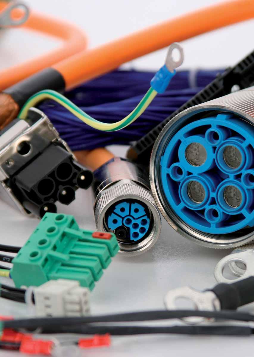
87 6. Cable assemblies


88 6. Cable assemblies Customer specific solutions with LÜTZE Tamper-proof connector Plastic-coated pin connector for industrial applications Allen-Bradley according to 2090 Standard for fixed wiring Servo motor cable 6.6 Feedback cable 6.7 for c-tracks Servo motor cable 6.8 Feedback cable 6.9 Hybrid cables 6.10 Bosch Rexroth Standard for c-tracks Servo motor cable according to IKG Standard 6.11 Servo motor cable according to RKL Standard 6.12 Feedback cable according to IKS Standard 6.13 Lenze Standard Servo motor cables 6.14 Feedback cable 6.15 SEW Standard Servo motor cables 6.16 Feedback cable 6.18 SIEMENS according to 6FX5002 for fixed wiring Servo cable assemblies without brake, Base cable 6.19 Servo cable assemblies with brake, Base cable 6.21 Servo cable assemblies without brake, Extension 6.23 Servo cable assemblies with brake, Extension 6.24 Feedback cable DRIVE-CLIQ, Base cable 6.25 SIEMENS according to 6FX8002 for c-tracks Servo cable assemblies without brake, Base cable 6.26 Servo cable assemblies with brake, Base cable 6.28 Servo cable assemblies without brake, Extension 6.30 Servo cable assemblies with brake, Extension 6.31 Feedback cable DRIVE-CLIQ, Base cable 6.32 Feedback cable, Base cable or Extension


89 6. Cable assemblies Pre-assembled cables for different applications Siemens Simatic SPS / S7 connector 6.34 Ethernet- Patch cable Cat.5E / Cat USB 3.0 connection cables 6.36 Prefabricated coil cables 6.37 Questionnaire Questionnaire for coil cables 6.38 Questionnaire for LÜTZE Tamper-proof connector 6.39 Ordering instructions: The LÜTZE Art.no. consists of two blocks that are separated by a dot: 6 digits before the dot: technical design 4-digits after the dot: lenght code in cm Special features: No minimum order quantity All intermediate lenghts in steps of 0.5 m are available within a short time When ordering, please specify serial number and lenght key Additional types on request Customer-specific solutions on request Our project planning sheet for cable assemblies can be found in the download area under 6.3


90 Always the right conne LÜTZE cable assemb Sealed as if potted! LÜTZE Tamper-proof plastic moulded round connectors M23 for industrial use offer the user an economical and, at the same time, safe solution for the electrical connection of machines and systems. The LÜTZE range offers varying numbers of terminations and cable lengths. That is numbers of terminations from 6 to 28 and ratings of up to 30 A at 630 V. Therefore robust, safe cabling is available for numerous signal and power applications. The integrated protection against kinking and the inner metal housing with 360 EMC shielding ensure the cable assemblies meet the requirements for the industrial sector - they really are sealed as if potted! Further advantages: Tamper-proof: unauthorised opening of the connector housing and incorrect connection in the connector are therefore excluded 100 % compatible with SIEMENS, BOSCH REXROTH, LENZE, SEW... Manufacture from a batch size of 1 Available at short notice Protection class IP66/67


91 ction: lies Coil cables for the highest mechanical stresses - manufactured according to your specifications, e.g. high-performance machines, lifting platforms and many other moving applications. Also suitable for outdoor use ideal for millions of cycles without failure! Customised solutions Every system is different. Take advantage of our experience in cable assembly! Our experts can document and provide solutions to your applications as they have access to more than cables, plugs, strain reliefs and cable conduits.
92 Servomotor cables for fixed installation According to Allen-Bradley 2090 standard Application For Allen-Bradley standard Connecting lead especially for frequency converters and SERVO drives in machine and plant construction, transport and conveyor technology Conform with NFPA79 for tool machine wiring Very suitable for extreme operating conditions and high interference signals In dry, damp and wet rooms Especially for industrial environments in mechanical and system engineering Properties High active and passive interference resistance (EMC) Easy installation Resistant to most mineral and vegetable-based cutting oils UV-resistant Silicone and talcum free RoHS compliant Technical data UL approval culus Nominal voltage 600 V UL TC 600 V UL MTW 600 V UL AWM 105 C 1000 V WTTC Voltage U 0 /U 0.6/1 kv Test voltage 4000 V Insulation resistance min. 500 M km Temperature range fixed -40 C to +90 C Minimum bending radius fixed D 6 Approvals UL TC-ER, UL/AWM/CE, UL MTW, WTTC UL AWM Style 20328, Class 1, Div. 2 per NEC Art. 336, 392, 501 C(UL) TC, CIC FT4, UL 1277 Oil Res I and II, RoHS Part-No. Allen-Bradley designation Length m Number of conductors/ cross-section Outer ca. mm Base cable SpeedTec CPWM7DF-16AAxx* 10.0 (4GAWG16) CPWM7DF-14AAxx* 10.0 (4GAWG14) CPWM7DF-12AAxx* 10.0 (4GAWG12) CPWM7DF-10AAxx* 10.0 (4GAWG10) CPWM7DF-08AAxx* 10.0 (4GAWG8) CPBM7DF-16AAxx* 10.0 (4GAWG16+(2 AWG18)) CPBM7DF-14AAxx* 10.0 (4GAWG14+(2 AWG18)) CPBM7DF-12AAxx* 10.0 (4GAWG12+(2 AWG18)) CPBM7DF-10AAxx* 10.0 (4GAWG10+(2 AWG18)) CPBM7DF-08AAxx* 10.0 (4GAWG8+(2 AWG18)) CPBM7DF-06AAxx* 10.0 (4GAWG6+(2 AWG18)) CPBM7DF-04AAxx* 10.0 (4GAWG4+(2 AWG18)) CPBM7DF-02AAxx* 10.0 (4GAWG2+(2 AWG18)) 34.1 Construction AWG conductor Conductor insulation Special PVC/nylon Conductor marking power conductor: brown, black, blue Ground conductor green/yellow according to DIN EN Control pair color-coded black, white Control pair with foil tape and braided shield. Conductors cabled in layers without mechanical stress, layer pitch optimised Braid from tinned copper wire, optical coverage 85 % Jacket special-tpe, matte, adhesion-free surface Jacket color orange RAL 2003 * Allen-Bradley article designations are registered trademarks of Rockwell Allen Bradley, and are for reference purposes only The product photos are not to scale and do not represent detailed images of the respective products. 6.6
93 Signal cables for fixed installation According to Allen-Bradley 2090 standard Application Feedback cables for Allen Bradley drives Conform with NFPA79 for tool machine wiring Very suitable for extreme operating conditions and high interference signals In dry, damp and wet rooms Especially for industrial environments in mechanical and system engineering Properties High active and passive interference resistance (EMC) Easy installation Specially developed TPE jacket for superior oil-resistance according to UL 1581 Resistant to most mineral and vegetable-based cutting oils UV-resistant Silicone and talcum-free RoHS compliant Technical data Nominal voltage 300 V UL PLTC-ER 300 V UL CM 600 V UL AWM 90 C Test Voltage 1.5 kv Temperature range -30 C to +105 C (static -40 C) Minimum bending radius min. D 6, static Burning behavior Flame retardant per UL Vertical-Tray UL VW-1 Oil resistance UL days in Oil at 100 C 60 days in Oil at 75 C Approvals A : UL PLTC-ER, meets NEC 725 and Class I Div. 2 A : UL CM, meets NEC 800 Both: UL AWM Style CE RoHS REACH Part-No. Allen-Bradley designation Length m Number of conductors/ cross-section Outer ca. mm Base cable SpeedTec CFBM7DF-CEAAxx* 10.0 (5 2 AWG22) CFBM7DD-CEAAxx* 10.0 (5 2 AWG22) 9.9 DIN thread XXNFMF-Sxx* 10.0 (2 AWG16+2 AWG A WG26) 13.6 Construction AWG conductor Flexible finely stranded bare copper conductors Conductor insulation Special PVC Conductor marking Conductors color-coded for specific system Aluminium laminated film shield, braid made of tinned copper wires, optical coverage approx. 85 %, drain wire Outer jacket Extreme oil-resistant TPE jacket Jacket color green RAL 6018 * Allen-Bradley article designations are registered trademarks of Rockwell Allen Bradley, and are for reference purposes only The product photos are not to scale and do not represent detailed images of the respective products. 6.7
94 Servomotor cables for C-tracks According to Allen-Bradley 2090 standard Application Servo cables for Allen Bradley drives Due to optimized cable construction optimally suited for continuous flexing applications in C-tracks Very good resitance against aggressive coolants and lubricants Especially for industrial environments in machines and plants Properties High active and passive interference resistance (EMC) Silicone free RoHS compliant Technical data UL approval AWM Nominal voltage 1000 V 80 C Test voltage 4000 V Temperature range moving -25 C to +80 C fixed -40 C to +80 C Minimum bending radius moving D 10 fixed D 6 Burning behavior Flame-retardant according to VDE 0482 T 265-2, IEC , UL 1581 section 1080 VW-1, CSA FT 1 Halogen free according to DIN EN Part-No. Allen-Bradley designation Length m Number of conductors/ cross-section Outer ca. mm Base cable SpeedTec CPWM7DF-16AFxx* 10.0 (4G1.5) CPWM7DF-10AFxx* 10.0 (4G6.0) CPBM7DF-10AFxx* 10.0 (4G6.0+(2 1.5)) CPBM7DF-16AFxx* 10.0 (4G1.5+(2 1.5)) CPWM7DF-14AFxx* 10.0 (4G2.5) CPBM7DF-14AFxx* 10.0 (4G2.5+(2 1.5)) CPWM7DF-08AFxx* 10.0 (4G10) CPBM7DF-08AFxx* 10.0 (4G10+(2 1.5)) 19.5 DIN thread CPBM4DF-16AFxx* 10.0 (4G1.5+(2 1.5)) CPWM4DF-16AFxx* 10.0 (4G1.5) CPBM4DF-14AFxx* 10.0 (4G2.5+(2 1.5)) CPWM4DF-14AFxx* 10.0 (4G2.5) 10.8 Extension SpeedTec CPBM7E7-16AFxx* 10.0 (4G1.5+(2 1.5)) CPBM7E7-10AFxx* 10.0 (4G6.0+(2 1.5)) CPBM7E7-14AFxx* 10.0 (4G2.5+(2 1.5)) CPBM7E7-08AFxx* 10.0 (4G10+(2 1.5)) 19.5 Construction Bare copper wire, super finely stranded according to DIN VDE 0295 class 6, IEC class 6 Special TPE/HGI conductor insulation, UL qualified Conductor marking Power conductors black with numbered print U/L1/C/L+, V/L2, W/L3/D/L- Ground conductor green/yellow according to DIN EN Control pair color-coded (bw, wb) or numbered (5/6/7/8) Control pair with braided shield and foil tape Conductors cabled in layers without mechanical stress, layer pitch optimised Fleece wrap over cable core Braid from tinned copper wire, optical coverage 85 % Outer jacket Full polyurethane jacket, matte, adhesion-free surface Jacket color orange RAL 2003 * Allen-Bradley article designations are registered trademarks of Rockwell Allen Bradley, and are for reference purposes only The product photos are not to scale and do not represent detailed images of the respective products. 6.8
95 Signal cables for C-tracks According to Allen-Bradley 2090 standard Application Servo feedback cables for Allen Bradley drives Due to optimized cable construction optimally suited for continuous flexing applications in C-tracks Very good resitance against aggressive coolants and lubricants Especially for industrial environments in machines and plants Properties High active and passive interference resistance (EMC) Silicone free RoHS compliant Technical data UL approval AWM Nominal voltage 1000 V 80 C Temperature range moving -25 C to +80 C fixed -40 C to +80 C Minimum bending radius moving D 12 fixed D 6 Burning behavior Flame-retardant according to VDE 0482 T 265-2, IEC , UL 1581 section 1080 VW-1, CSA FT 1 Halogen free according to DIN EN Part-No. Allen-Bradley designation Length m Number of conductors/cross-section Outer ca. mm Base cable SpeedTec CFBM7DF-CEAFxx* 10.0 (5 2 AWG22) CFBM7DF-CDAFxx* 10.0 (2 AWG AWG AWG26) CFBM7DD-CEAFxx* 10.0 (5 2 AWG22) 9.2 DIN thread CFBM4DF-CDAFxx* 10.0 (2 AWG16+2 AWG AWG26) 10.8 Extension SpeedTec CFBM7E7-CEAFxx* 10.0 (5 2 AWG22) CFBM7E7-CDAFxx* 10.0 (2 AWG16+2 AWG AWG26) 10.8 Construction Bare copper wire, super finely stranded according to DIN VDE 0295 class 6, IEC class 6 Special TPE, UL certified Conductor marking Conductors color-coded for specific system Ground conductor green/yellow according to DIN EN G = with green/yellow ground conductor, = without ground conductor Conductors cabled in layers without mechanical stress, layer pitch optimised Fleece wrap over cable core Braid from tinned copper wire, optical coverage 85 % Outer jacket Full polyurethane jacket, matte, adhesion-free surface Jacket color green RAL 6018 * Allen-Bradley article designations are registered trademarks of Rockwell Allen Bradley, and are for reference purposes only The product photos are not to scale and do not represent detailed images of the respective products. 6.9
96 Hybrid cables for C-tracks According to Allen-Bradley 2090 standard Application Combined power supply cable with motor supply, brake and digital feedback especially for SERVO drives in machine and plant construction, transport and conveyor technology Due to Full PUR jacket and TPE / HGI conductor insulation optimally suited for c-tracks, extremely rough operating conditions and aggressive coolants and lubricants Especially for industrial environments in mechanical and system engineering Properties High active and passive interference resistance (EMC) Braided shield optimised for continuous flexible use Very good alternating bending strength Low adhesion, abrasion-resistant, nick-resistant, tear-propagation-resistant Hydrolysis-resistant, microbe-resistant, and rot-resistant Weatherproof, ozone and UV resistant (normal lighting conditions) Good ruggedness and salt water resistance Excellent coolant and lubricant resistance Resistant to most oils, greases, alcohol-free benzines and kerosene Halogen free Silicone and talcum free RoHS compliant Technical data UL approval AWM Nominal voltage 1000 V 80 C Test voltage 3000 V Insulation resistance min. 500 M km Temperature range moving -25 C to +80 C fixed -40 C to +80 C Minimum bending radius moving D 7.5 fixed D 5 Burning behavior Flame-retardant according to VDE 0482 T 265-2, DIN EN , IEC , UL 1581 section 1080 VW-1, CSA FT 1 Halogen free according to DIN EN Part-No. Allen-Bradley designation Length m Number of conductors/cross-section Outer ca. mm Base cable SpeedTec CSWM1DF-18AFxx* 10.0 (4G1.0+(2 AWG22)) CSWM1DF-14AFxx* 10.0 (4G2.5+(2 AWG22)) CSWM1DF-10AFxx* 10.0 (4G6+(2 AWG22)) CSBM1DF-18AFxx* 10.0 (4G1,0+(2 0,75) (2 AWG22)) CSBM1DF-14AFxx* 10.0 (4G2,5+(2 1,0)+( AWG22)) CSBM1DF-10AFxx* 10.0 (4G6+(2 1.0)+ (2 AWG22)) 17.8 Extension SpeedTec CSBM1E1-18AFxx* 10.0 (4G1,0+(2 0,75)+( AWG22)) CSBM1E1-14AFxx* 10.0 (4G2,5+(2 1,0)+ (2 AWG22)) 14.0 Construction Bare copper wire, finely stranded according to DIN VDE 0295 class 6, IEC class 6 Conductor insulation Polyolefin Conductor marking Power conductors black with numbered print U/L1/C/L+, V/L2, W/L3/D/L- Ground conductor green/yellow according to DIN EN G = with green/yellow ground conductor, = without ground conductor Control pair color-coded (bw, wb), BUS element color-coded (bw, wb) Control pair and BUS element each with braided shield and foil tape Conductor for the power supply, element brake and element BUS braided together Fleece wrap over cable core Braid from tinned copper wire, optical coverage 85 % Jacket special-pur, matte, adhesion-free surface Jacket color orange RAL 2003 * Allen-Bradley article designations are registered trademarks of Rockwell Allen Bradley, and are for reference purposes only The product photos are not to scale and do not represent detailed images of the respective products. 6.10
97 Servomotor cables for C-tracks According to Bosch Rexroth IKG standard Application Motor cable for Bosch Rexroth SERVO drives Full PUR jacket and TPE conductor insulation optimally suited for c-tracks, extremely rough operating conditions, aggressive coolants and lubricants Properties Silicone free RoHS-compliant Technical data UL approval curus Nominal voltage 1000 V 80 C Voltage U 0 /U 0.6/1 kv Insulation resistance min. 500 M km Temperature range moving -25 C to +80 C fixed -40 C to +80 C Minimum bending radius moving D 10 fixed D 6 Burning behavior Flame-retardant according to VDE 0482 T 265-2, DIN EN 50265/2, IEC , UL 1581 section 1080 VW-1 CSA FT 1 Halogen free according to DIN EN Product photo The product photos are not to scale and do not represent detailed images of the respective products. Construction Jacket color orange RAL 2003 Part-No. INDRAMAT designation Length m Number of conductors/ cross-section Outer ca. mm IKG 0006/10.0* 10.0 (4G1.5+2 (2 0.75)) IKG 0050/10.0* 10.0 (4G2.5+2 (2 0.75)) IKG 0081/10.0* 10.0 (4G6+2 (2 1.5)) IKG 0143/10.0* 10.0 (4G16+2 (2 1.5)) IKG 0314/10.0* 10.0 (4G2.5+2 (2 0.75)) IKG 0331/10.0* 10.0 (4G (2 0.5)) IKG 0332/10.0* 10.0 (4G (2 0.5)) IKG 4009/10.0* 10.0 (4G1.5+2 (2 0.75)) IKG 4016/10.0* 10.0 (4G1.5+2 (2 0.75)) IKG 4017/10.0* 10.0 (4G1.5+2 (2 0.75)) IKG 4018/10.0* 10.0 (4G1.5+2 (2 0.75)) IKG 4020/10.0* 10.0 (4G1.5+2 (2 0.75)) IKG 4047/10.0* 10.0 (4G1.5+2 (2 0.75)) IKG 4050/10.0* 10.0 (4G1.5+2 (2 0.75)) IKG 4055/10.0* 10.0 (4G1.5+2 (2 0.75)) IKG 4060/10.0* 10.0 (4G1.5+2 (2 0.75)) IKG 4067/10.0* 10.0 (4G2.5+2 (2 0.75)) IKG 4070/10.0* 10.0 (4G2.5+2 (2 0.75)) IKG 4087/10.0* 10.0 (4G4+2 (2 1.5)) IKG 4090/10.0* 10.0 (4G4+2 (2 1.5)) IKG 4107/10.0* 10.0 (4G6+2 (2 1.5)) IKG 4117/10.0* 10.0 (4G4+2 (2 1.5)) IKG 4118/10.0* 10.0 (4G6+2 (2 0.75)) IKG 4119/10.0* 10.0 (4G1.0+2 (2 0.75)) IKG 4122/10.0* 10.0 (4G10+2 (2 1.5)) IKG 4127/10.0* 10.0 (4G10+2 (2 1.5)) IKG 4138/10.0* 10.0 (4G1.0+2 (2 0.75)) IKG 4139/10.0* 10.0 (4G2.5+2 (2 0.75)) IKG 4150/10.0* 10.0 (4G6+2 (2 1.5)) IKG 4172/10.0* 10.0 (4G16+2 (2 1.5)) IKG 4176/10.0* 10.0 (4G10+2 (2 1.5)) IKG 4186/10.0* 10.0 (4G16+2 (2 1.5)) IKG 4193/10.0* 10.0 (4G16+2 (2 1.5)) IKG 4204/10.0* 10.0 (4G25+2 (2 1.5)) IKG 4224/10.0* 10.0 (4G35+2 (2 1.5)) 31.4 * Bosch Rexroth article designations are registered trademarks of Bosch Rexroth, and are for reference purposes only 6.11
98 Servomotor cables for C-tracks According to Bosch Rexroth RKL standard Application Motor cable for Bosch Rexroth SERVO drives Full PUR jacket and TPE conductor insulation optimally suited for c-tracks, extremely rough operating conditions, aggressive coolants and lubricants Properties Silicone free RoHS-compliant Technical data UL approval curus Nominal voltage 1000 V 80 C Voltage U 0 /U 0.6/1 kv Insulation resistance min. 500 M km Temperature range moving -25 C to +80 C fixed -40 C to +80 C Minimum bending radius moving D 10 fixed D 6 Burning behavior Flame-retardant according to VDE 0482 T 265-2, DIN EN 50265/2, IEC , UL 1581 section 1080 VW-1 CSA FT 1 Halogen free according to DIN EN Product photo The product photos are not to scale and do not represent detailed images of the respective products. Construction Jacket color orange RAL 2003 Part-No. INDRAMAT designation Length m Number of conductors/cross-section Outer ca. mm RKL 4302/10.0* 10.0 (4G1.0+2 (2 0.75)) RKL 4303/10.0* 10.0 (4G1.0+2 (2 0.75)) RKL 4306/10.0* 10.0 (4G1.5+2 (2 0.75)) RKL 4308/10.0* 10.0 (4G2.5+2 (2 0.75)) RKL 4309/10.0* 10.0 (4G2.5+2 (2 0.75)) RKL 4310/10.0* 10.0 (4G2.5+2 (2 0.75)) RKL 4311/10.0* 10.0 (4G1.5+2 (2 0.75)) RKL 4312/10.0* 10.0 (4G2.5+2 (2 0.75)) RKL 4314/10.0* 10.0 (4G4+2 (2 1.5)) RKL 4317/10.0* 10.0 (4G6+2 (2 1.5)) RKL 4318/10.0* 10.0 (4G6+2 (2 1.5)) RKL 4320/10.0* 10.0 (4G1.5+2 (2 0.75)) RKL 4321/10.0* 10.0 (4G2.5+2 (2 0.75)) RKL 4323/10.0* 10.0 (4G6+2 (2 1.5)) RKL 4324/10.0* 10.0 (4G10+2 (2 1.5)) RKL 4328/10.0* 10.0 (4G6+2 (2 1.5)) RKL 4329/10.0* 10.0 (4G10+2 (2 1.5)) RKL 4330/10.0* 10.0 (4G16+2 (2 1.5)) RKL 4331/10.0* 10.0 (4G25+2 (2 1.5)) RKL 4337/10.0* 10.0 (4G4+2 (2 1.5)) RKL 4338/10.0* 10.0 (4G6+2 (2 1.5)) RKL 4339/10.0* 10.0 (4G10+2 (2 1.5)) RKL 4340/10.0* 10.0 (4G16+2 (2 1.5)) RKL 4341/10.0* 10.0 (4G25+2 (2 1.5)) RKL 4343/10.0* 10.0 (4G2.5+2 (2 0.75)) RKL 4518/10.0* 10.0 (4G25+2 (2 1.5)) RKL 4519/10.0* 10.0 (4G35+2 (2 1.5)) RKL 4603/10.0* 10.0 (4G2.5+2 (2 0.75)) RKL 4606/10.0* 10.0 (4G6+2 (2 1.5)) RKL 4612/10.0* 10.0 (4G25+2 (2 1.5)) RKL 0013/10.0* 10.0 (4G (2 0.5)) RKL 0014/10.0* 10.0 (4G1.0+2 (2 0.75)) 11.1 * Bosch Rexroth article designations are registered trademarks of Bosch Rexroth, and are for reference purposes only 6.12
99 Signal cables for C-tracks According to Bosch Rexroth IKS standard Application Signal cables Due to full PUR jacket and TPE conductor insulation optimally suited for c-track, extremely rough operating conditions, aggressive coolants and lubricants Properties Silicone free RoHS-compliant Technical data UL approval curus Nominal voltage 300 V 80 C Voltage U 0 /U 0.6/1 kv Insulation resistance min. 200 M km Temperature range moving -25 C to +80 C fixed -40 C to +80 C Minimum bending radius moving D 12 fixed D 6 Burning behavior Flame-retardant according to VDE 0482 T 265-2, DIN EN 50265/2, IEC , UL 1581 section 1080 VW-1 CSA FT 1 Halogen free according to DIN EN Product photo The product photos are not to scale and do not represent detailed images of the respective products. Part-No. INDRAMAT designation Length m IKS 0230/10.0* IKS 0232/10.0* IKS 0253/10.0* IKS 0257/10.0* IKS 4001/10.0* IKS 4038/10.0* IKS 4042/10.0* IKS 4043/10.0* IKS 4103/10.0* IKS 4151/10.0* IKS 4153/10.0* IKS 4374/10.0* IKS 4389/10.0* IKS 0251/10.0* IKS 0301/10.0* IKS 0321/10.0* IKS 0374/10.0* IKS 0252/10.0* RKG 0002/10.0* RKG 4200/10.0* RKG 4201/10.0* RKG 0033/10.0* Outer ca. mm Construction Jacket color orange RAL 2003 * Bosch Rexroth article designations are registered trademarks of Bosch Rexroth, and are for reference purposes only 6.13
100 Servomotor cables According to LENZE-Standard Application Servo cables for LENZE SERVO drives Especially for industrial environments, machines and plants For fixed installation PVC outer jacket, PVC conductor insulation, flame-retardant, suitable for fixed installation For use as C-track chains Due to full PUR jacket and TPE conductor insulation optimally suited for c-tracks, extremely rough operating conditions, aggressive coolants and lubricants Properties Silicone free RoHS-compliant Technical data UL approval curus Nominal voltage 1000 V 80 C Voltage U 0 /U 0.6/1 kv Insulation resistance min. 500 M km Temperature range PVC cable moving -5 C to +80 C fixed -25 C to +80 C PUR cable moving -25 C to +80 C fixed -40 C to +80 C Minimum bending radius moving D 10 fixed D 6 Burning behavior Flame-retardant according to VDE 0482 T 265-2, DIN EN 50265/2, IEC , UL 1581 section 1080 VW-1 CSA FT 1 Halogen free according to DIN EN Product photo The product photos are not to scale and do not represent detailed images of the respective products. Part-No. LENZE description* Length m Number of conductors/cross-section Outer ca. mm For fixed installation EWLM-010GM-015* 10.0 (4G1.5+(2 1.5)) EWLM-010GM-025* 10.0 (4G2.5+(2 1.5)) EWLM-010GM-040* 10.0 (4G4+(2 1.5)) EYP-0003-A-0100-M01-A00* 10.0 (4G1.5) 9.5 For use as C-track chains EWLM-010GMS-015* 10.0 (4G1.5+(2 1.5)) EWLM-010GMS-025* 10.0 (4G2.5+(2 1.5)) EWLM-010GMS-040* 10.0 (4G4+(2 1.5)) 14.9 Construction Jacket color orange RAL 2003 * LENZE article designations are registered trademarks of LENZE AG, and are for reference purposes only 6.14
101 Signal cables According to LENZE-Standard Application LENZE encoder cables For fixed installation PVC outer jacket, PVC conductor insulation, flame-retardant, suitable for fixed installation For use as C-track chains Due to full PUR jacket and TPE conductor insulation optimally suited for c-tracks, extremely rough operating conditions, aggressive coolants and lubricants Properties Silicone free RoHS-compliant Technical data UL approval curus Nominal voltage 300 V 80 C Voltage U 0 /U 0.6/1 kv Insulation resistance min. 200 M km Temperature range PVC cable moving -5 C to +80 C fixed -25 C to +80 C PUR cable moving -25 C to +80 C fixed -40 C to +80 C Minimum bending radius moving D 12 fixed D 7.5 Burning behavior Flame-retardant according to VDE 0482 T 265-2, DIN EN 50265/2, IEC , UL 1581 section 1080 VW-1 CSA FT 1 Halogen free according to DIN EN Product photo The product photos are not to scale and do not represent detailed images of the respective products. Part-No. LENZE description* Length m Outer ca. mm Encoder cables for fixed installation EWLE-010GM-T* Encoder cables for C-track chains EWLE-010GMS-T* Resolver cables for hard wiring EWLR-010GM-T* Resolver cables for C-track chains EWLR-010GMS-T* EWLR-010ZMS-T* EYF-0020-A-0100-F01-S04* Construction Jacket color green RAL 6018 * LENZE article designations are registered trademarks of LENZE AG, and are for reference purposes only 6.15
102 Servomotor cables According to SEW standard base and extension cables Application Servo cables for SEW drives Especially for industrial environments, machines and plants For fixed installation PVC outer jacket, PVC conductor insulation, flame-retardant, suitable for fixed installation For use as C-track chains Due to full PUR jacket and TPE conductor insulation optimally suited for C-tracks, extremely rough operating conditions, aggressive coolants and lubricants Properties Silicone free RoHS-compliant Technical data UL approval curus Nominal voltage 1000 V 80 C Voltage U 0 /U 0.6/1 kv Insulation resistance min. 500 M km Temperature range PVC cable moving -5 C to +80 C fixed -25 C to +80 C PUR cable moving -25 C to +80 C fixed -40 C to +80 C Minimum bending radius moving D 10 fixed D 7.5 Burning behavior Flame-retardant according to VDE 0482 T , IEC , UL 1581 section 1080 VW-1 CSA FT 1 Halogen free according to DIN EN Product photo The product photos are not to scale and do not represent detailed images of the respective products. Part-No. SEW description Length m Number of conductors/cross-section Outer ca. mm Base cables for fixed installation * 10.0 (4G1.5) * 10.0 (4G1.5+(3 1.0)) * 10.0 (4G1.5+(3 1.0)) 12.3 Base cables for C-track chains * 10.0 (4G1.5) * 10.0 (4G1.5+(3 1.0)) * 10.0 (4G1.5+(3 1.0)) * 10.0 (4G2.5+(3 1.0)) * 10.0 (4G4+(3 1.0)) * 10.0 (4G6+(3 1.5)) * 10.0 (4G10+(3 1.5)) 20.5 Extensions for C-track chains * 10.0 (4G1.5) * 10.0 (4G2.5) * 10.0 (4G4) * 10.0 (4G1.5+(3 1.0)) * 10.0 (4G2.5+(3 1.0)) * 10.0 (4G4+(3 1.0)) 15.3 Construction Jacket color orange RAL 2003 * SEW article designations are registered trademarks of SEW- Eurodrive GmbH & Co KG, and are for reference purposes only 6.16
103 Servomotor cables According to SEW standard base and extension cables Application Servomotor cables for SEW drives Especially for industrial environments, machines and plants For fixed installation PVC outer jacket, PVC conductor insulation, flame-retardant, suitable for fixed installation For use as C-track chains Due to full PUR jacket and TPE conductor insulation optimally suited for c-track, extremely rough operating conditions, aggressive coolants and lubricants Properties Silicone free RoHS-compliant Technical data UL approval curus Nominal voltage 1000 V 80 C Voltage U 0 /U 0.6/1 kv Insulation resistance min. 500 M km Temperature range PVC cable moving -5 C to +80 C fixed -25 C to +80 C PUR cable moving -25 C to +80 C fixed -40 C to +80 C Minimum bending radius moving D 10 fixed D 7.5 Burning behavior Flame-retardant according to VDE 0482 T , IEC , UL 1581 section 1080 VW-1 CSA FT 1 Halogen free according to DIN EN Product photo The product photos are not to scale and do not represent detailed images of the respective products. Construction Jacket color orange RAL 2003 Part-No. SEW description Length m Number of conductors/crosssection Outer ca. mm Motor base cables for fixed installation * 10.0 (4G1.5) * 10.0 (4G2.5) * 10.0 (4G4) X* 10.0 (4G6) * 10.0 (4G10) 17.8 Brake motor base cables for fixed installation * 10.0 (4G1.5+(3 1.0)) * 10.0 (4G2.5+(3 1.0)) * 10.0 (4G4+(3 1.0)) * 10.0 (4G6+(3 1.5)) * 10.0 (4G10+(3 1.5)) 20.0 Moro extensions for fixed installation * 10.0 (4G2.5) * 10.0 (4G4) * 10.0 (4G6) X* 10.0 (4G10) 17.8 Brake motor extensions for fixed installation X* 10.0 (4G1.5+(3 1.0)) * 10.0 (4G2.5+(3 1.0)) * 10.0 (4G4+(3 1.0)) * 10.0 (4G6+(3 1.5)) * 10.0 (4G10+(3 1.5)) 20.0 Motor base cables for C-tracks * 10.0 (4G1.5) * 10.0 (4G2.5) * 10.0 (4G4) * 10.0 (4G6) * 10.0 (4G10) 17.8 Brake motor extensions for C-tracks * 10.0 (4G1.5+(3 1.0)) * 10.0 (4G2.5+(3 1.0)) * 10.0 (4G4+(3 1.0)) * 10.0 (4G6+(3 1.5)) * 10.0 (4G10+(3 1.5)) 20.0 Motor extensions for C-tracks * 10.0 (4G1.5) * 10.0 (4G2.5) * 10.0 (4G4) * 10.0 (4G6) * 10.0 (4G10) 17.8 Brake motor extensions for C-tracks * 10.0 (4G1.5+(3 1.0)) * 10.0 (4G2.5+(3 1.0)) X* 10.0 (4G4+(3 1.0)) * 10.0 (4G6+(3 1.5)) * 10.0 (4G10+(3 1.5)) 20.0 * SEW article designations are registered trademarks of SEW- Eurodrive GmbH & Co KG, and are for reference purposes only 6.17
104 Signal cables According to SEW standard Application SEW resolver and encoder cables Especially for industrial environments, machines and plants For fixed installation PVC outer jacket, PVC conductor insulation, flame-retardant, suitable for fixed installation For use as C-track chains Due to full PUR jacket and TPE conductor insulation optimally suited for c-tracks, extremely rough operating conditions, aggressive coolants and lubricants Properties Silicone free RoHS-compliant Technical data UL approval curus Nominal voltage 300 V 80 C Voltage U 0 /U 0.6/1 kv Insulation resistance min. 200 M km Temperature range PVC cable moving -5 C to +80 C fixed -25 C to +80 C PUR cable moving -25 C to +80 C fixed -40 C to +80 C Minimum bending radius moving D 12 fixed D 7.5 Burning behavior Flame-retardant according to VDE 0482 T 265-2, DIN EN 50265/2, IEC , UL 1581 section 1080 VW-1 CSA FT 1 Halogen free according to DIN EN Product photo The product photos are not to scale and do not represent detailed images of the respective products. Part-No. SEW description Length m Outer ca. mm For fixed installation * * * * * * For use as C-track chains * * * * * * Construction Jacket color green RAL 6018 * SEW article designations are registered trademarks of SEW- Eurodrive GmbH & Co KG, and are for reference purposes only 6.18
105 Servo cable assemblies without brake cores for fixed installation Acc. to SIEMENS-6FX5002 standard Base cable Application Base cable for Siemens servo drives For flexible applications without continuous flexing More cost-effective alternative to the cable chain version 6FX8002 Properties PVC Flame-retardant, self-extinguishing Silicone free RoHS-compliant Technical data UL approval curus Nominal voltage 1000 V 80 C Voltage U 0 /U 0.6/1 kv Test voltage 4000 V Insulation resistance min. 500 M km Temperature range moving -5 C to +80 C fixed -25 C to +80 C Minimum bending radius moving D 10 fixed D 6 Burning behavior Flame-retardant according to VDE 0482 T 265-2, DIN EN , IEC , UL 1581 section 1080 VW-1, CSA FT 1 Product photo The product photos are not to scale and do not represent detailed images of the respective products. Part-No. SIEMENS designation Length m Number of conductors/ cross-section Outer ca. mm SINAMICS, speed-connect/booksize FX5002-5CN01-1BA0* 10.0 (4G1.5) FX5002-5CN11-1BA0* 10.0 (4G2.5) FX5002-5CN21-1BA0* 10.0 (4G1.5) FX5002-5CN31-1BA0* 10.0 (4G2.5) FX5002-5CN41-1BA0* 10.0 (4G4) FX5002-5CN51-1BA0* 10.0 (4G6) FX5002-5CN61-1BA0* 10.0 (4G10) 16.5 SINAMICS, full thread/booksize FX5002-5CS01-1BA0* 10.0 (4G1.5) FX5002-5CS11-1BA0* 10.0 (4G2.5) FX5002-5CS13-1BA0* 10.0 (4G10) FX5002-5CS21-1BA0* 10.0 (4G1.5) FX5002-5CS31-1BA0* 10.0 (4G2.5) FX5002-5CS41-1BA0* 10.0 (4G4) FX5002-5CS51-1BA0* 10.0 (4G6) FX5002-5CS61-1BA0* 10.0 (4G10) 16.5 SINAMICS, open end/booksize FX5002-5CS02-1BA0* 10.0 (4G1.5) FX5002-5CS12-1BA0* 10.0 (4G2.5) FX5002-5CS42-1BA0* 10.0 (4G4) FX5002-5CS52-1BA0* 10.0 (4G6) FX5002-5CS62-1BA0* 10.0 (4G10) 16.5 Construction Bare copper wire, multi-strand according to DIN VDE 0295 class 5, IEC class 5 Special TPM/PP-conductor insulation, UL certified Conductor marking Power conductors black with numbered print U/L1/C/L+, V/L2, W/L3/D/L- Ground conductor green/yellow according to DIN EN Fleece wrap over cable core Braid from tinned copper wire, optical coverage 85 % Jacket color orange RAL 2003 * Siemens article designations are registered trademarks of Siemens AG, and are for reference purposes only 6.19
106 Servo cable assemblies without brake cores for fixed installation Acc. to SIEMENS-6FX5002 standard Base cable Application Base cable for Siemens servo drives For flexible applications without continuous flexing More cost-effective alternative to the cable chain version 6FX8002 Properties PVC Flame-retardant, self-extinguishing Silicone free RoHS-compliant Technical data UL approval curus Nominal voltage 1000 V 80 C Voltage U 0 /U 0.6/1 kv Test voltage 4000 V Insulation resistance min. 500 M km Temperature range moving -5 C to +80 C fixed -25 C to +80 C Minimum bending radius moving D 10 fixed D 6 Burning behavior Flame-retardant according to VDE 0482 T 265-2, DIN EN , IEC , UL 1581 section 1080 VW-1, CSA FT 1 Product photo The product photos are not to scale and do not represent detailed images of the respective products. Part-No. SIEMENS designation Length m Number of conductors/ cross-section Outer ca. mm SIMODRIVE, full thread/open end FX5002-5CA01-1BA0* 10.0 (4G1.5) FX5002-5CA11-1BA0* 10.0 (4G2.5) FX5002-5CA13-1BA0* 10.0 (4G10) FX5002-5CA21-1BA0* 10.0 (4G1.5) FX5002-5CA23-1BA0* 10.0 (4G16) FX5002-5CA31-1BA0* 10.0 (4G2.5) FX5002-5CA41-1BA0* 10.0 (4G4) FX5002-5CA51-1BA0* 10.0 (4G6) FX5002-5CA61-1BA0* 10.0 (4G10) 16.5 SINAMICS, full thread/open end FX5002-5CG01-1BA0* 10.0 (4G1.5) FX5002-5CG11-1BA0* 10.0 (4G2.5) FX5002-5CG13-1BA0* 10.0 (4G10) FX5002-5CG21-1BA0* 10.0 (4G1.5) FX5002-5CG23-1BA0* 10.0 (4G16) FX5002-5CG31-1BA0* 10.0 (4G2.5) FX5002-5CG41-1BA0* 10.0 (4G4) FX5002-5CG51-1BA0* 10.0 (4G6) FX5002-5CG61-1BA0* 10.0 (4G10) FX5002-5CS14-1BA0* 10.0 (4G10) FX5002-5CS23-1BA0* 10.0 (4G16) FX5002-5CS54-1BA0* 10.0 (4G6) FX5002-5CS64-1BA0* 10.0 (4G10) FX5002-5CG32-1BA0* 10.0 (4G2.5) 10.6 Construction Bare copper wire, multi-strand according to DIN VDE 0295 class 5, IEC class 5 Special TPM/PP-conductor insulation, UL certified Conductor marking Power conductors black with numbered print U/L1/C/L+, V/L2, W/L3/D/L- Ground conductor green/yellow according to DIN EN Fleece wrap over cable core Braid from tinned copper wire, optical coverage 85 % Jacket color orange RAL 2003 * Siemens article designations are registered trademarks of Siemens AG, and are for reference purposes only 6.20
107 Servo cable assemblies with brake cores for fixed installation Acc. to SIEMENS-6FX5002 standard Base cable Application Base cable for Siemens servo drives For flexible applications without continuous flexing More cost-effective alternative to the cable chain version 6FX8002 Properties PVC Flame-retardant, self-extinguishing Silicone free RoHS-compliant Technical data UL approval curus Nominal voltage 1000 V 80 C Voltage U 0 /U 0.6/1 kv Test voltage 4000 V Insulation resistance min. 500 M km Temperature range moving -5 C to +80 C fixed -25 C to +80 C Minimum bending radius moving D 10 fixed D 6 Burning behavior Flame-retardant according to VDE 0482 T 265-2, DIN EN , IEC , UL 1581 section 1080 VW-1, CSA FT 1 Product photo The product photos are not to scale and do not represent detailed images of the respective products. Part-No. SIEMENS designation Length m Number of conductors/cross-section Outer ca. mm SINAMICS, speed-connect/booksize FX5002-5DN01-1BA0* 10.0 (4G1.5+(2 1.5)) FX5002-5DN11-1BA0* 10.0 (4G2.5+(2 1.5)) FX5002-5DN21-1BA0* 10.0 (4G1.5+(2 1.5)) FX5002-5DN31-1BA0* 10.0 (4G2.5+(2 1.5)) FX5002-5DN41-1BA0* 10.0 (4G4+(2 1.5)) FX5002-5DN51-1BA0* 10.0 (4G6+(2 1.5)) FX5002-5DN61-1BA0* 10.0 (4G10+(2 1.5)) 18.5 SINAMICS, full thread/booksize FX5002-5DS01-1BA0* 10.0 (4G1.5+(2 1.5)) FX5002-5DS11-1BA0* 10.0 (4G2.5+(2 1.5)) FX5002-5DS13-1BA0* 10.0 (4G10+(2 1.5)) FX5002-5DS21-1BA0* 10.0 (4G1.5+(2 1.5)) FX5002-5DS31-1BA0* 10.0 (4G2.5+(2 1.5)) FX5002-5DS41-1BA0* 10.0 (4G4+(2 1.5)) FX5002-5DS51-1BA0* 10.0 (4G6+(2 1.5)) FX5002-5DS61-1BA0* 10.0 (4G10+(2 1.5)) 18.5 Construction Bare copper wire, multi-strand according to DIN VDE 0295 class 5, IEC class 5 Special TPM/PP-conductor insulation, UL certified Conductor marking Power conductors black with numbered print U/L1/C/L+, V/L2, W/L3/D/L- Ground conductor green/yellow according to DIN EN Signal conductor: white/black (1 pair) Fleece wrap over cable core Braid from tinned copper wire, optical coverage 85 % Jacket color orange RAL 2003 * Siemens article designations are registered trademarks of Siemens AG, and are for reference purposes only 6.21
108 Servo cable assemblies with brake cores for fixed installation Acc. to SIEMENS-6FX5002 standard Base cable Application Base cable for Siemens servo drives For flexible applications without continuous flexing More cost-effective alternative to the cable chain version 6FX8002 Properties PVC Flame-retardant, self-extinguishing Silicone free RoHS-compliant Technical data UL approval curus Nominal voltage 1000 V 80 C Voltage U 0 /U 0.6/1 kv Test voltage 4000 V Insulation resistance min. 500 M km Temperature range moving -5 C to +70 C fixed -25 C to +70 C Minimum bending radius moving D 10 fixed D 6 Burning behavior Flame-retardant according to VDE 0482 T 265-2, DIN EN , IEC , UL 1581 section 1080 VW-1, CSA FT 1 Product photo The product photos are not to scale and do not represent detailed images of the respective products. Construction Bare copper wire, multi-strand according to DIN VDE 0295 class 5, IEC class 5 Special TPM/PP-conductor insulation, UL certified Conductor marking Power conductors black with numbered print U/L1/C/L+, V/L2, W/L3/D/L- Ground conductor green/yellow according to DIN EN Control pair color-coded (bk, wh) Control pair with braided shield and foil tape Fleece wrap over cable core Braid from tinned copper wire, optical coverage 85 % Jacket color orange RAL 2003 Part-No. SIEMENS designation Length m Number of conductors/crosssection Outer ca. mm SIMODRIVE, full thread/open end FX5002-5DA01-1BA0* 10.0 (4G1.5+(2 1.5)) FX5002-5DA11-1BA0* 10.0 (4G2.5+(2 1.5)) FX5002-5DA13-1BA0* 10.0 (4G10+(2 1.5)) FX5002-5DA21-1BA0* 10.0 (4G1.5+(2 1.5)) FX5002-5DA23-1BA0* 10.0 (4G16+(2 1.5)) FX5002-5DA31-1BA0* 10.0 (4G2.5+(2 1.5)) FX5002-5DA33-1BA0* 10.0 (4G25+(2 1.5)) FX5002-5DA41-1BA0* 10.0 (4G4+(2 1.5)) FX5002-5DA51-1BA0* 10.0 (4G6+(2 1.5)) FX5002-5DA61-1BA0* 10.0 (4G10+(2 1.5)) 18.5 SINAMICS, full thread/open end FX5002-5DG01-1BA0* 10.0 (4G1.5+(2 1.5)) FX5002-5DG11-1BA0* 10.0 (4G2.5+(2 1.5)) FX5002-5DG13-1BA0* 10.0 (4G10+(2 1.5)) FX5002-5DG21-1BA0* 10.0 (4G1.5+(2 1.5)) FX5002-5DG23-1BA0* 10.0 (4G16+(2 1.5)) FX5002-5DG31-1BA0* 10.0 (4G2.5+(2 1.5)) FX5002-5DG33-1BA0* 10.0 (4G25+(2 1.5)) FX5002-5DG41-1BA0* 10.0 (4G4+(2 1.5)) FX5002-5DG51-1BA0* 10.0 (4G6+(2 1.5)) FX5002-5DG61-1BA0* 10.0 (4G10+(2 1.5)) FX5002-5DS14-1BA0* 10.0 (4G10+(2 1.5)) FX5002-5DS23-1BA0* 10.0 (4G16+(2 1.5)) FX5002-5DS54-1BA0* 10.0 (4G6+(2 1.5)) FX5002-5DS64-1BA0* 10.0 (4G10+(2 1.5)) 18.5 * Siemens article designations are registered trademarks of Siemens AG, and are for reference purposes only 6.22
109 Servo cable assemblies without brake cores for fixed installation Acc. to SIEMENS-6FX5002 standard Extension Application Base cable for Siemens servo drives For flexible applications without continuous flexing More cost-effective alternative to the cable chain version 6FX8002 Properties PVC Flame-retardant, self-extinguishing Silicone free RoHS-compliant Notes: The extension can also be used for SPEED-CONNECT plug connection, for this the O-ring must be removed on the outer thread. This does not affect the tightness of the plug connection. Technical data UL approval curus Nominal voltage 1000 V 80 C Voltage U 0 /U 0.6/1 kv Test voltage 4000 V Insulation resistance min. 500 M km Temperature range moving -5 C to +80 C fixed -25 C to +80 C Minimum bending radius moving D 10 fixed D 6 Burning behavior Flame-retardant according to VDE 0482 T 265-2, DIN EN , IEC , UL 1581 section 1080 VW-1, CSA FT 1 Product photo The product photos are not to scale and do not represent detailed images of the respective products. Part-No. SIEMENS designation Length m Number of conductors/ cross-section Outer ca. mm SINAMICS/SIMODRIVE, full thread FX5002-5CA05-1BA0* 10.0 (4G1.5) FX5002-5CA15-1BA0* 10.0 (4G2.5) FX5002-5CA28-1BA0* 10.0 (4G1.5) FX5002-5CA38-1BA0* 10.0 (4G2.5) FX5002-5CA48-1BA0* 10.0 (4G4) FX5002-5CA58-1BA0* 10.0 (4G6) FX5002-5CA68-1BA0* 10.0 (4G10) FX5002-5CX18-1BA0* 10.0 (4G10) FX5002-5CX28-1BA0* 10.0 (4G16) 21.2 Construction Bare copper wire, multi-strand according to DIN VDE 0295 class 5, IEC class 5 Special TPM/PP-conductor insulation, UL certified Conductor marking Power conductors black with numbered print U/L1/C/L+, V/L2, W/L3/D/L- Ground conductor green/yellow according to DIN EN Fleece wrap over cable core Braid from tinned copper wire, optical coverage 85 % Jacket color orange RAL 2003 * Siemens article designations are registered trademarks of Siemens AG, and are for reference purposes only 6.23
110 Servo cable assemblies with brake cores for fixed installation Acc. to SIEMENS-6FX5002 standard Extension Application Extension, for Siemens servo drives For flexible application without continuous flexing Cost-effective alternative to the c-tracks suitable 6FX8002 version Properties PVC Flame-retardant, self-extinguishing Silicone free RoHS-compliant Notes: The extension can also be used for SPEED-CONNECT plug connection, for this the O-ring must be removed on the outer thread. This does not affect the tightness of the plug connection. Technical data UL approval curus Nominal voltage 1000 V 80 C Voltage U 0 /U 0.6/1 kv Test voltage 4000 V Insulation resistance min. 500 M km Temperature range moving -5 C to +80 C fixed -25 C to +80 C Minimum bending radius moving D 10 fixed D 6 Burning behavior Flame-retardant according to VDE 0482 T 265-2, DIN EN , IEC , UL 1581 section 1080 VW-1, CSA FT 1 Product photo The product photos are not to scale and do not represent detailed images of the respective products. Part-No. SIEMENS designation Length m Number of con- Outer ductors/cross-sec- tion ca. mm SINAMICS/SIMODRIVE, full thread FX5002-5DA05-1BA0* 10.0 (4G1.5+(2 1.5)) FX5002-5DA15-1BA0* 10.0 (4G2.5+(2 1.5)) FX5002-5DA28-1BA0* 10.0 (4G1.5+(2 1.5)) FX5002-5DA38-1BA0* 10.0 (4G2.5+(2 1.5)) FX5002-5DA48-1BA0* 10.0 (4G4+(2 1.5)) FX5002-5DA58-1BA0* 10.0 (4G6+(2 1.5)) FX5002-5DA68-1BA0* 10.0 (4G10+(2 1.5)) FX5002-5DX18-1BA0* 10.0 (4G10+(2 1.5)) FX5002-5DX28-1BA0* 10.0 (4G16+(2 1.5)) FX5002-5DX38-1BA0* 10.0 (4G25+(2 1.5)) 28.5 Construction Bare copper wire, multi-strand according to DIN VDE 0295 class 5, IEC class 5 Special TPM/PP-conductor insulation, UL certified Conductor marking Power conductors black with numbered print U/L1/C/L+, V/L2, W/L3/D/L- Ground conductor green/yellow according to DIN EN Control pair color-coded (bk, wh) Control pair with braided shield and foil tape Fleece wrap over cable core Braid from tinned copper wire, optical coverage 85 % Jacket color orange RAL 2003 * Siemens article designations are registered trademarks of Siemens AG, and are for reference purposes only 6.24
111 Signal cables for fixed installation According to SIEMENS-6FX5002 standard Base cable DRIVE-CLIQ Application Resolver cable For flexible application without continuous flexing Cost-effective alternative to the c-tracks suitable 6FX8002 version Properties Silicone free RoHS-compliant Technical data UL approval curus Nominal voltage 30 V 80 C Test voltage 500 V Insulation resistance min. 20 M km Temperature range moving -5 C to +80 C fixed -25 C to +80 C Minimum bending radius moving D 15 fixed D 7.5 Burning behavior Flame-retardant according to VDE 0482 T 265-2, DIN EN , IEC Product photo The product photos are not to scale and do not represent detailed images of the respective products. Part-No. SIEMENS designation Length m Outer ca. mm SINAMICS FX5002-2DC00-1BA0* FX5002-2DC10-1BA0* FX5002-2DC20-1BA0* Construction Bare copper wire, multi-strand according to DIN VDE 0295 class 5, IEC class 5 Special thermoplastic conductor insulation Color coded conductor Ground conductor green/yellow according to DIN EN Braid from tinned copper wire, optical coverage 85 % Jacket special PVC TM2 according to HD21.1, matte, adhesionfree surface Jacket color green RAL 6018 * Siemens article designations are registered trademarks of Siemens AG, and are for reference purposes only 6.25
112 Servo cable assemblies without brake cores for C-tracks Acc. to SIEMENS-6FX8002 standard Base cable Application Base cable DRIVE-CLIQ, for SIEMENS SERVO drives Due to full PUR jacket and TPE conductor insulation optimally suited for c-tracks, extremely rough operating conditions, aggressive coolants and lubricants Especially for industrial environments, machines and plants Properties Silicone free RoHS-compliant Technical data UL approval curus Nominal voltage 1000 V 80 C Voltage U 0 /U 0.6/1 kv Test voltage 4000 V Insulation resistance min. 500 M km Temperature range moving -25 C to +80 C fixed -40 C to +80 C Minimum bending radius moving D 10 fixed D 6 Burning behavior Flame-retardant according to VDE 0482 T 265-2, DIN EN , IEC , UL 1581 section 1080 VW-1, CSA FT 1 Halogen free according to DIN EN Product photo The product photos are not to scale and do not represent detailed images of the respective products. Part-No. SIEMENS designation Length m Number of conductors/ cross-section Outer ca. mm SINAMICS, speed-connect/booksize FX8002-5CN01-1BA0* 10.0 (4G1.5) FX8002-5CN11-1BA0* 10.0 (4G2.5) FX8002-5CN21-1BA0* 10.0 (4G1.5) FX8002-5CN31-1BA0* 10.0 (4G2.5) FX8002-5CN41-1BA0* 10.0 (4G4) FX8002-5CN51-1BA0* 10.0 (4G6) FX8002-5CN61-1BA0* 10.0 (4G10) 17.6 SINAMICS, full thread/booksize FX8002-5CS01-1BA0* 10.0 (4G1.5) FX8002-5CS11-1BA0* 10.0 (4G2.5) FX8002-5CS13-1BA0* 10.0 (4G10) FX8002-5CS21-1BA0* 10.0 (4G1.5) FX8002-5CS31-1BA0* 10.0 (4G2.5) FX8002-5CS41-1BA0* 10.0 (4G4) FX8002-5CS51-1BA0* 10.0 (4G6) FX8002-5CS61-1BA0* 10.0 (4G10) 17.6 SINAMICS, open end/booksize FX8002-5CS02-1BA0* 10.0 (4G1.5) FX8002-5CS12-1BA0* 10.0 (4G2.5) FX8002-5CS42-1BA0* 10.0 (4G4) FX8002-5CS52-1BA0* 10.0 (4G6) FX8002-5CS62-1BA0* 10.0 (4G10) 17.6 Construction Bare copper wire, finely stranded according to DIN VDE 0295 class 6, IEC class 6 Special TPE/HGI conductor insulation, UL qualified Conductor marking Power conductors black with numbered print U/L1/C/L+, V/L2, W/L3/D/L- Ground conductor green/yellow according to DIN EN Conductors cabled in layers without mechanical stress, layer pitch optimised Fleece wrap over cable core Braid from tinned copper wire, optical coverage 85 % Full polyurethane jacket, matte, adhesion-free surface Jacket color orange RAL 2003 * Siemens article designations are registered trademarks of Siemens AG, and are for reference purposes only 6.26
113 Servo cable assemblies without brake cores for C-tracks Acc. to SIEMENS-6FX8002 standard Base cable Application Base cable, for Siemens servo drives Due to full PUR jacket and TPE conductor insulation optimally suited for c-tracks, extremely rough operating conditions, aggressive coolants and lubricants Properties Silicone free RoHS-compliant Technical data UL approval curus Nominal voltage 1000 V 80 C Voltage U 0 /U 0.6/1 kv Test voltage 4000 V Insulation resistance min. 500 M km Temperature range moving -25 C to +80 C fixed -40 C to +80 C Minimum bending radius moving D 10 fixed D 6 Burning behavior Flame-retardant according to VDE 0482 T 265-2, DIN EN , IEC , UL 1581 section 1080 VW-1, CSA FT 1 Halogen free according to DIN EN Product photo The product photos are not to scale and do not represent detailed images of the respective products. Part-No. SIEMENS designation Length m Number of conductors/ cross-section Outer ca. mm SIMODRIVE, full thread/open end FX8002-5CA01-1BA0* 10.0 (4G1.5) FX8002-5CA11-1BA0* 10.0 (4G2.5) FX8002-5CA13-1BA0* 10.0 (4G10) FX8002-5CA21-1BA0* 10.0 (4G1.5) FX8002-5CA23-1BA0* 10.0 (4G16) FX8002-5CA31-1BA0* 10.0 (4G2.5) FX8002-5CA41-1BA0* 10.0 (4G4) FX8002-5CA51-1BA0* 10.0 (4G6) FX8002-5CA61-1BA0* 10.0 (4G10) 17.6 SINAMICS, full thread/open end FX8002-5CG01-1BA0* 10.0 (4G1.5) FX8002-5CG11-1BA0* 10.0 (4G2.5) FX8002-5CG13-1BA0* 10.0 (4G10) FX8002-5CG21-1BA0* 10.0 (4G1.5) FX8002-5CG23-1BA0* 10.0 (4G16) FX8002-5CG31-1BA0* 10.0 (4G2.5) FX8002-5CG41-1BA0* 10.0 (4G4) FX8002-5CG51-1BA0* 10.0 (4G6) FX8002-5CG61-1BA0* 10.0 (4G10) FX8002-5CS14-1BA0* 10.0 (4G10) FX8002-5CS23-1BA0* 10.0 (4G16) FX8002-5CS54-1BA0* 10.0 (4G6) FX8002-5CS64-1BA0* 10.0 (4G10) FX8002-5CG32-1BA0* 10.0 (4G2.5) 10.8 Construction Bare copper wire, finely stranded according to DIN VDE 0295 class 6, IEC class 6 Special TPE/HGI conductor insulation, UL qualified Conductor marking Power conductors black with numbered print U/L1/C/L+, V/L2, W/L3/D/L- Ground conductor green/yellow according to DIN EN Conductors cabled in layers without mechanical stress, layer pitch optimised Braid from tinned copper wire, optical coverage 85 % Full polyurethane jacket, matte, adhesion-free surface Jacket color orange RAL 2003 * Siemens article designations are registered trademarks of Siemens AG, and are for reference purposes only 6.27
114 Servo cable assemblies with brake cores for C-tracks Acc. to SIEMENS-6FX8002 standard Base cable Application Base cable for Siemens servo drives Full PUR jacket and TPE conductor insulation optimally suited for c-tracks, extremely rough operating conditions, aggressive coolants and lubricants Especially for industrial environments, machines and plants Properties Silicone free RoHS-compliant Technical data UL approval curus Nominal voltage 1000 V 80 C Voltage U 0 /U 0.6/1 kv Test voltage 4000 V Insulation resistance min. 500 M km Temperature range moving -25 C to +80 C fixed -40 C to +80 C Minimum bending radius moving D 10 fixed D 6 Burning behavior Flame-retardant according to VDE 0482 T 265-2, DIN EN , IEC , UL 1581 section 1080 VW-1, CSA FT 1 Halogen free according to DIN EN , EN Product photo The product photos are not to scale and do not represent detailed images of the respective products. Part-No. SIEMENS designation Length m Number of conductors/cross-section Outer ca. mm SINAMICS, speed-connect/booksize FX8002-5DN01-1BA0* 10.0 (4G1.5+(2 1.5)) FX8002-5DN11-1BA0* 10.0 (4G2.5+(2 1.5)) FX8002-5DN21-1BA0* 10.0 (4G1.5+(2 1.5)) FX8002-5DN31-1BA0* 10.0 (4G2.5+(2 1.5)) FX8002-5DN41-1BA0* 10.0 (4G4+(2 1.5)) FX8002-5DN51-1BA0* 10.0 (4G6+(2 1.5)) FX8002-5DN61-1BA0* 10.0 (4G10+(2 1.5)) 19.5 SINAMICS, full thread/booksize FX8002-5DS01-1BA0* 10.0 (4G1.5+(2 1.5)) FX8002-5DS11-1BA0* 10.0 (4G2.5+(2 1.5)) FX8002-5DS21-1BA0* 10.0 (4G1.5+(2 1.5)) FX8002-5DS31-1BA0* 10.0 (4G2.5+(2 1.5)) FX8002-5DS41-1BA0* 10.0 (4G4+(2 1.5)) FX8002-5DS51-1BA0* 10.0 (4G6+(2 1.5)) FX8002-5DS61-1BA0* 10.0 (4G10+(2 1.5)) FX8002-5DS13-1BA0* 10.0 (4G10+(2 1.5)) 19.5 Construction Bare copper wire, finely stranded according to DIN VDE 0295 class 6, IEC class 6 Special TPE/HGI conductor insulation, UL certified Conductor marking Power conductors black with numbered print U/L1/C/L+, V/L2, W/L3/D/L- Ground conductor green/yellow according to DIN EN Control pair color-coded (bk, wh) Control pair with braided shield and foil tape Conductors cabled in layers without mechanical stress, layer pitch optimised Fleece wrap over cable core Braid from tinned copper wire, optical coverage 85 % Outer jacket Full polyurethane jacket, matte, adhesion-free surface Jacket color orange RAL 2003 * Siemens article designations are registered trademarks of Siemens AG, and are for reference purposes only 6.28
115 Servo cable assemblies with brake cores for C-tracks Acc. to SIEMENS-6FX8002 standard Base cable Application Base cable, for Siemens servo drives Due to full PUR jacket and TPE conductor insulation optimally suited for c-tracks, extremely rough operating conditions, aggressive coolants and lubricants Especially for industrial environments, machines and plants Properties Silicone free RoHS-compliant Technical data UL approval curus Nominal voltage 1000 V 80 C Voltage U 0 /U 0.6/1 kv Test voltage 4000 V Insulation resistance min. 500 M km Temperature range moving -25 C to +80 C fixed -40 C to +80 C Minimum bending radius moving D 10 fixed D 6 Burning behavior Flame-retardant according to VDE 0482 T 265-2, DIN EN , IEC , UL 1581 section 1080 VW-1, CSA FT 1 Halogen free according to DIN EN , EN Product photo The product photos are not to scale and do not represent detailed images of the respective products. Construction Bare copper wire, finely stranded according to DIN VDE 0295 class 6, IEC class 6 Special TPE/HGI conductor insulation, UL certified Conductor marking Power conductors black with numbered print U/L1/C/L+, V/L2, W/L3/D/L- Ground conductor green/yellow according to DIN EN Control pair color-coded (bk, wh) Control pair with braided shield and foil tape Conductors cabled in layers without mechanical stress, layer pitch optimised Fleece wrap over cable core Braid from tinned copper wire, optical coverage 85 % Outer jacket Full polyurethane jacket, matte, adhesion-free surface Jacket color orange RAL 2003 Part-No. SIEMENS designation Length m Number of conductors/crosssection Outer ca. mm SIMODRIVE, full thread/open end FX8002-5DA01-1BA0* 10.0 (4G1.5+(2 1.5)) FX8002-5DA11-1BA0* 10.0 (4G2.5+(2 1.5)) FX8002-5DA13-1BA0* 10.0 (4G10+(2 1.5)) FX8002-5DA21-1BA0* 10.0 (4G1.5+(2 1.5)) FX8002-5DA23-1BA0* 10.0 (4G16+(2 1.5)) FX8002-5DA31-1BA0* 10.0 (4G2.5+(2 1.5)) FX8002-5DA33-1BA0* 10.0 (4G25+(2 1.5)) FX8002-5DA41-1BA0* 10.0 (4G4+(2 1.5)) FX8002-5DA43-1BA0* 10.0 (4G35+(2 1.5)) FX8002-5DA51-1BA0* 10.0 (4G6+(2 1.5)) FX8002-5DA61-1BA0* 10.0 (4G10+(2 1.5)) 19.5 SINAMICS, full thread/open end FX8002-5DG01-1BA0* 10.0 (4G1.5+(2 1.5)) FX8002-5DG11-1BA0* 10.0 (4G2.5+(2 1.5)) FX8002-5DG13-1BA0* 10.0 (4G10+(2 1.5)) FX8002-5DG21-1BA0* 10.0 (4G1.5+(2 1.5)) FX8002-5DG23-1BA0* 10.0 (4G16+(2 1.5)) FX8002-5DG31-1BA0* 10.0 (4G2.5+(2 1.5)) FX8002-5DG33-1BA0* 10.0 (4G25+(2 1.5)) FX8002-5DG41-1BA0* 10.0 (4G4+(2 1.5)) FX8002-5DG43-1BA0* 10.0 (4G35+(2 1.5)) FX8002-5DG51-1BA0* 10.0 (4G6+(2 1.5)) FX8002-5DG53-1BA0* 10.0 (4G50+(2 1.5)) FX8002-5DG61-1BA0* 10.0 (4G10+(2 1.5)) FX8002-5DS14-1BA0* 10.0 (4G10+(2 1.5)) FX8002-5DS23-1BA0* 10.0 (4G16+(2 1.5)) FX8002-5DS54-1BA0* 10.0 (4G6+(2 1.5)) FX8002-5DS64-1BA0* 10.0 (4G10+(2 1.5)) 19.5 * Siemens article designations are registered trademarks of Siemens AG, and are for reference purposes only 6.29
116 Servo cable assemblies without brake cores for C-tracks Acc. to SIEMENS-6FX8002 standard Extension Application Extension, for Siemens servo drives Due to full PUR jacket and TPE conductor insulation optimally suited for c-tracks, extremely rough operating conditions, aggressive coolants and lubricants Properties Silicone free RoHS-compliant Notes: The extension can also be used for SPEED-CONNECT plug connection, for this the O-ring must be removed on the outer thread. This does not affect the tightness of the plug connection. Technical data UL approval curus Nominal voltage 1000 V 80 C Voltage U 0 /U 0.6/1 kv Test voltage 4000 V Insulation resistance min. 500 M km Temperature range moving -25 C to +80 C fixed -40 C to +80 C Minimum bending radius moving D 10 fixed D 6 Burning behavior Flame-retardant according to VDE 0482 T 265-2, DIN EN , IEC , UL 1581 section 1080 VW-1, CSA FT 1 Halogen free according to DIN EN , EN Product photo The product photos are not to scale and do not represent detailed images of the respective products. Part-No. SIEMENS designation Length m Number of conductors/ cross-section Outer ca. mm SINAMICS/SIMODRIVE, full thread FX8002-5CA05-1BA0* 10.0 (4G1.5) FX8002-5CA15-1BA0* 10.0 (4G2.5) FX8002-5CA28-1BA0* 10.0 (4G1.5) FX8002-5CA38-1BA0* 10.0 (4G2.5) FX8002-5CA48-1BA0* 10.0 (4G4) FX8002-5CA58-1BA0* 10.0 (4G6) FX8002-5CA68-1BA0* 10.0 (4G10) FX8002-5CX18-1BA0* 10.0 (4G10) FX8002-5CX28-1BA0* 10.0 (4G16) 21.2 SINAMICS, speed-connect FX8002-5CN05-1BA0* (4G1.5) 8.6 Construction Bare copper wire, finely stranded according to DIN VDE 0295 class 6, IEC class 6 Special TPE/HGI conductor insulation, UL certified Conductor marking Power conductors black with numbered print U/L1/C/L+, V/L2, W/L3/D/L- Ground conductor green/yellow according to DIN EN Conductors cabled in layers without mechanical stress, optimised lay pitch Fleece wrap over cable core Braid from tinned copper wire, optical coverage 85 % Outer jacket Full polyurethane jacket, matte, adhesion-free surface Jacket color orange RAL 2003 * Siemens article designations are registered trademarks of Siemens AG, and are for reference purposes only 6.30
117 Servo cable assemblies with brake cores for C-tracks Acc. to SIEMENS-6FX8002 standard Extension Application Extension, for Siemens servo drives Due to full PUR jacket and TPE conductor insulation optimally suited for c-tracks, extremely rough operating conditions, aggressive coolants and lubricants Especially for industrial environments, machines and plants Properties Silicone free RoHS-compliant The extension can also be used for SPEED-CONNECT plug connection, for this the O-ring must be removed on the outer thread. This does not affect the tightness of the plug connection. Technical data UL approval curus Nominal voltage 1000 V 80 C Voltage U 0 /U 0.6/1 kv Test voltage 4000 V Insulation resistance min. 500 M km Temperature range moving -25 C to +80 C fixed -40 C to +80 C Minimum bending radius moving D 10 fixed D 6 Burning behavior Flame-retardant according to VDE 0482 T 265-2, DIN EN , IEC , UL 1581 section 1080 VW-1, CSA FT 1 Halogen free according to DIN EN Product photo The product photos are not to scale and do not represent detailed images of the respective products. Part-No. SIEMENS designation Length Number of conductors/cross-section Outer m ca. mm SINAMICS/SIMODRIVE, full thread FX8002-5DA05-1BA0* 10.0 (4G1.5+(2 1.5)) FX8002-5DA15-1BA0* 10.0 (4G2.5+(2 1.5)) FX8002-5DA28-1BA0* 10.0 (4G1.5+(2 1.5)) FX8002-5DA38-1BA0* 10.0 (4G2.5+(2 1.5)) FX8002-5DA48-1BA0* 10.0 (4G4+(2 1.5)) FX8002-5DA58-1BA0* 10.0 (4G6+(2 1.5)) FX8002-5DA68-1BA0* 10.0 (4G10+(2 1.5)) FX8002-5DX18-1BA0* 10.0 (4G10+(2 1.5)) FX8002-5DX28-1BA0* 10.0 (4G16+(2 1.5)) FX8002-5DX38-1BA0* 10.0 (4G25+(2 1.5)) FX8002-5DX48-1BA0* 10.0 (4G35+(2 1.5)) FX8002-5DX58-1BA0* 10.0 (4G50+(2 1.5)) 37.3 SINAMICS, speed-connect FX8002-5DN05-1BA0* (4G1.5+(2 1.5)) 11.4 Construction Bare copper wire, finely stranded according to DIN VDE 0295 class 6, IEC class 6 Special TPE/HGI conductor insulation, UL certified Conductor marking Power conductors black with numbered print U/L1/C/L+, V/L2, W/L3/D/L- Ground conductor green/yellow according to DIN EN Control pair color-coded (bk, wh) Control pair with braided shield and foil tape Conductors cabled in layers without mechanical stress, optimised lay pitch Fleece wrap over cable core Braid from tinned copper wire, optical coverage 85 % Outer jacket Full polyurethane jacket, matte, adhesion-free surface Jacket color orange RAL 2003 * Siemens article designations are registered trademarks of Siemens AG, and are for reference purposes only 6.31
118 Signal cables for C-tracks Acc. to SIEMENS-6FX8002 standard Base cable DRIVE-CLIQ Application Resolver cable Due to full PUR jacket and TPE conductor insulation optimally suited for c-tracks, extremely rough operating conditions, aggressive coolants and lubricants Properties Silicone free RoHS-compliant Technical data UL approval curus Nominal voltage 30 V 80 C Test voltage 500 V Insulation resistance min M km Temperature range moving -25 C to +80 C fixed -40 C to +80 C Minimum bending radius moving D 12 fixed D 6 Burning behavior Flame-retardant according to VDE 0482 T 265-2, DIN EN 50265/2, IEC , UL 1581 section 1080 VW-1 CSA FT 1 Halogen free according to DIN EN Product photo The product photos are not to scale and do not represent detailed images of the respective products. Part-No. SIEMENS designation Length m Outer ca. mm SINAMICS FX8002-2DC00-1BA0* FX8002-2DC10-1BA0* FX8002-2DC20-1BA0* Construction Bare copper wire, finely stranded according to DIN VDE 0295 class 6, IEC class 6 Special TPE conductor insulation, UL qualified Conductors color-coded for specific system Conductors cabled in layers without mechanical stress, layer pitch optimised Fleece wrap over cable core Braid from tinned copper wire, optical coverage 85 % Full polyurethane jacket, matte adhesion-free surface Jacket color green RAL 6018 * Siemens article designations are registered trademarks of Siemens AG, and are for reference purposes only 6.32
119 Signal cables for C-tracks Acc. to SIEMENS-6FX8002 standard base cable and extension Application Resolver cable Due to full PUR jacket and TPE conductor insulation optimally suited for c-tracks, extremely rough operating conditions, aggressive coolants and lubricants Properties Silicone free RoHS-compliant Technical data UL approval curus Nominal voltage 30 V 80 C Test voltage 500 V Insulation resistance min M km Temperature range moving -25 C to +80 C fixed -40 C to +80 C Minimum bending radius moving D 12 fixed D 6 Burning behavior Flame-retardant according to VDE 0482 T 265-2, DIN EN 50265/2, IEC , UL 1581 section 1080 VW-1 CSA FT 1 Halogen free according to DIN EN Product photo The product photos are not to scale and do not represent detailed images of the respective products. Part-No. SIEMENS designation Length m Outer ca. mm SIMODRIVE base cable FX8002-2AD00-1BA0* FX8002-2AH00-1BA0* FX8002-2CA11-1BA0* FX8002-2CA15-1BA0* FX8002-2CA31-1BA0* FX8002-2CA51-1BA0* FX8002-2CA61-1BA0* FX8002-2CB51-1BA0* FX8002-2CC11-1BA0* FX8002-2CD01-1BA0* FX8002-2CF02-1BA0* FX8002-2CG00-1BA0* FX8002-2CH00-1BA0* FX8002-2EQ10-1BA0* FX8002-2CA21-1BA0* FX8002-2CE07-1BA0* SIMODRIVE extension FX8002-2CA34-1BA0* FX8002-2CF04-1BA0* FX8002-2EQ14-1BA0* FX8002-2AD04-1BA0* FX8002-2CB54-1BA0* Construction Bare copper wire, finely stranded according to DIN VDE 0295 class 6, IEC class 6 Special TPE conductor insulation, UL qualified Conductors color-coded for specific system Conductors cabled in layers without mechanical stress, layer pitch optimised Fleece wrap over cable core Braid from tinned copper wire, optical coverage 85 % Full polyurethane jacket, matte adhesion-free surface Jacket color green RAL 6018 * Siemens article designations are registered trademarks of Siemens AG, and are for reference purposes only 6.33
120 Pre-fabricated front-end plug S7 S7 Plug For Siemens Simatic PLC/S7 Application Wiring from Siemens Simatic PLC/S7 Properties Cable core with S7 connector Completely wired, 2. cables run at 90 to connector Technical data Conductor marking Packaging Construction Fully compatible to Siemens Color of conductor dark blue RAL5010 white number imprint, corresponding to the terminal location on the plug 3 m or 5 m Other lengths are available upon request Part-No. Type Cable core Cable construction Length m S7 Plug with screw termination AJ 20-pole AJ 20-pole AJ 20-pole AJ 20-pole AJ 20-pole AJ 20-pole AL 48-pole AL 48-pole AL 48-pole AL 48-pole AL 48-pole AL 48-pole S7 Plug with Easy-Connect Compatible to 392 1AM 40-pole Compatible to 392 1AM 40-pole Compatible to 392 1AM 40-pole Compatible to 392 1AM 40-pole Compatible to 392 1AM 40-pole Compatible to 392 1AM 40-pole
121 Patch cable, shielded Patch cable Cat 5E / Cat 6 Application Ethernet network wiring Properties Straight connector Assignment according to EIA/TIA 568B Moulded sleeve with length imprint (not for c-tracks suitable and industrial construction) Various colors available (not for c-tracks suitable and industrial construction) Technical data Connector Shielded RJ45, 3μ 50μ AU Wiring according to EIA/TIA 568B 1:1 or crossover Construction Fully plug compatible to IEC Cable Cat.5E: (4 2 AWG26) SFTP Cat.5E c-tracks suitable: PUR yellow (4 2 AWG26/19) SUTP Oil-resistant according to EN Alternating bending test (with load) according to VDE0472 T603 Cat.6: (4 2 AWG27) SSTP Cat.6 industrial version: PUR red (4 2 AWG27/7) SSTP Resistant to mineral oil, ASTM oil and UV radiation, highly abrasion-resistant Suitable for outdoor areas, but not for laying directly in earth Halogen free 1:1 wiring: cables and protective sleeves in same color The following colors can be supplied: grey, green, blue, yellow, red, black Crossover wiring: Cable in grey, protective sleeves in red C-track compatible PUR: Cable and protective sleeves yellow Part-No. Color Wiring Length m Cat.5E grey 1: blue 1: green 1: grey/ul 1:1 1.0 Cat.5E grey Crossover 1.0 Cat.5E C-track compatible PUR yellow 1:1 1.0 Cat grey 1: yellow 1: green 1:1 1.0 Cat.6 industrial version PUR red 1:
122 USB 3.0 (Super-Speed USB) USB 3.0 connection cables Application Connection technology for serial bus system Properties With the new standard USB 3.0, also called Super-Speed USB, transmission rates of up to 5Gbit/s are possible. This is equivalent to ten times the USB 2.0 standard. USB 3.0 remains downward compatible with the existing USB 2.0 devices. Technical data Operating voltage 30 V Temperature range to + 80 C Outer 5,5 ± 0,2 mm Part-No. Description Length m Color USB 3.0 cable A/A 1.0 blue USB 3.0 cable A/A 1:1 1.0 blue USB 3.0 cable A/B 1.0 blue USB 3.0 cable B/B 1.0 blue USB 3.0 Micro B/A male 1.0 black USB 3.0 cable A/A female 1.0 blue Construction Jacket color black, blue cables and sleeves in the same color RoHS compliant 6.36
123 PUR Coil cables unshielded LÜTZE PURFLEX Application Machine and device construction, transport and conveyor technology Especially for industrial environments, machines and plants Lifting platforms, test benches and measuring systems as well as door drives Properties Very good restoring force Low adhesion, abrasion-proof, nick-resistant, tear-propagationresistant Hydrolisis-resistant, microbe-resistant, and rot-resistant Weatherproof, ozone and UV resistant (normal lighting conditions) Good industrial- and salt water resistance Resistant to most oils, greases, alcohol-free benzines and kerosene Free from paint wetting disruptive substances (LABS-free), RoHS-compliant Technical data Voltage U 0 /U 300/500 V Test voltage 3000 V Insulation resistance min. 20 M km Temperature range moving -20 C to +80 C unmoving -40 C to +80 C Part-No. Number of conductors/cross-section Coil- mm Spiral length L0 mm Max. extension length L mm Connection end L1/L2 mm PURFLEX G G G G G G G G G G G G G G G G G G G Construction Bare copper wire, multi-strand according to DIN VDE 0295 class 5, IEC class 5 Special PVC conductor insulation Conductors colored according to DIN VDE (new) 2-wire: brown, blue 3-wire: greenyellow, brown, blue 4-wire: greenyellow, brown, black, grey 5-wire: greenyellow, blue, brown, black, grey starting with 6 conductors black with white number print according to DINEN50334 Ground conductor green/yellow according to DIN EN in the top layer Polyurethane jacket, matte, adhesion-free surface Jacket color up to 7-wires orange RAL 2003 starting with 12-wires black RAL 9005 Cable outlet radial CE These products are in conformity with the EU Low Voltage Directive 2006/95/EC 6.37
124 Design questionnaire for Coil cables Company: Contact person: Department: Street address: Postal code, city/town: Telephone: Fax: Germany Friedrich Lütze GmbH Tel.: Fax: (-288) Great Britain LUTZE Ltd. Tel.: Fax: USA LUTZE INC. Tel.: Fax: Please let us know your requirements using this design questionnaire for coil cables: L: mm L0: mm Ø AD: mm Ø WD: mm L1: mm L2: mm L3: mm L4: mm L5: mm L6: mm Quantity: pcs. Cable outlets, radial Purpose Installation situation: Winding direction: Standard cable art. no.: Jacket insulation material: Number of strands: Strand cross-section: mm 2 Shielding: yes no Please fill out this questionnaire and fax it back to us. We will be happy to give you a quotation. Thank you! Comments Cable outlets, radial and axial Cable outlets, axial 6.38
125 Construction questionnaire for LÜTZE Tamper-proof connector Company: Contact person: Department: Street address: Postal code, city/town: Telephone: Fax: Germany Friedrich Lütze GmbH Tel.: Fax: (-288) Great Britain LUTZE Ltd. Tel.: Fax: USA LUTZE INC. Tel.: Fax: Please tell us your requirements by filling in this construction questionnaire: Batch size: pieces Page 1 Page 2 Page 1 / View X Signal Pin layouts (more on request) Power clockwise counterclockwise 6-pin 7-pin 8+1-pin 9-pin 12-pin 17-pin 16+3-pin 6-pin 8-pin 9-pin Options Connector inner thread M23 x 1 Connector speedtec quick release fastener Coupling outer thread M23 x 1 Coupling speedtec quick release fastener Socket contacts pin contacts Signal coding: Cable Assembly length L: mm LÜTZE cable part number: Description / Requirement / Purpose / Specification: Page 2 / View Y Signal Pin layouts (more on request) Power clockwise counterclockwise 6-pin 7-pin 8+1-pin 9-pin 12-pin 17-pin 16+3-pin 6-pin 8-pin 9-pin Options Connector inner thread M23 x 1 Connector speedtec quick release fastener Coupling outer thread M23 x 1 Coupling speedtec quick release fastener Socket contacts pin contacts Signal coding: Other connectors Type/Version: Manufacturer: Manufacturer part number: Manipulation cable end (strip, remove insulation, change screen, shrink tubing, copper tape etc.) Description: Cable end cut smoothly Labelling Wrap-round label printing text distance to connector: Cable printing text distance to connector: Other labelling Description: No labelling Note: Please indicate pin assignment! 6.39
126 Notes 6.40

127 7. Actuator sensor interface
 7.13-7.14 M8 / open End - Cables 7.15-7.21 M8 / M8 - Cables 7.22-7.23 M12 / open End - Cables 7.24-7.")


128 7. Actuator sensor interface Actuator sensor cables M12 - Fieldbus cables (CANopen, DeviceNet and PROFIBUS) M12 - Network cables (PROFINET) M8 / open End - Cables M8 / M8 - Cables M12 / open End - Cables M12 / M8 - Cables 7.37 M12 / M12 - Cables M12 - Valve connector Connector, assembled freely M8 - Connector M12 - Connector M12, M12 / M8 - Connector T piece 7.55 M12 - Connector for Field and netsystems RJ45 Connector RJ45 Module holder 7.64 Panel connectors M8 and M12 Panel connectors USB - Panel connectors RJ45 - Panel connectors 7.69 M12 - RJ45 Control cabinet bushing 7.70 Accessories M8, M12 Protective cover 7.71 M8, M12 Designation plate, designation sleeve 7.72 Classification Ethernet Cable and -connector

129 LÜTZE SUPERFLEX and LÜTZE SUPERFLEX PLUS LÜTZE SUPERFLEX sets Industry Standards: longevity, reliability, flexibility LÜTZE SUPERFLEX flexing cables are specifically designed for use in continuous motion applications such as drag chains. Find here more informations about LÜTZE SUPERFLEX
130 Actuator sensor interface CANopen field bus cables Male M12 straight with PUR cable, shielded 360, open end self-locking screwed connection c-track compatible, halogen free Description Part-No. Type PU Cable length (m) STG5-M12/CAN 2M-PUR STG5-M12/CAN 5M-PUR STG5-M12/CAN 10M-PUR 1 Dimensions PIN assignment Circuit diagram SH Technical data Nominal voltage AC/DC 24 V Nominal voltage range max. 30 V Rated current 4 A Pol number 5 Cable length (m) Status Indication Current Consumption per LED Coding A Shielding 360 General Form M12 1, male straight Rated insulation voltage (EN 50178) 60 V Test voltage 1.5 kv Pollution degree 3 Insulation resistance >10 9 Contact resistance < 5 m Class of flammability according to UL 94 V0 Protection class IP65/IP67 Housing material TPU black Contact material CuSn, gold plated nickel Thread material Zinc die-casting, nickel-plated Gasket Cable construction 2 AWG 22/ AWG 24/19 + Drainwire AWG 22/19 Cable jacket PUR, RAL 4001 violet Conductor insulation PE Cable diameter 6.7 mm Bending radius 15 x cable diameter Storage temperature range -40 C 90 C Temperature range connector -25 C 90 C Temperature range cable fixed -40 C 80 C Temperature range cable moving -20 C 75 C Mechanical service life Weight (kg/piece) Approvals the cable is UL, CSA certified V Accessories Article number Type PU Cable markers 4 23mm LB M8/M12 5 Torque setting tool M DM-SET M12 1 Comments Angled onstruction item no xxxx 7.4
131 Actuator sensor interface CANopen field bus cables Female M12 straight with PUR cable, shielded 360, open end self-locking screwed connection c-track compatible, halogen free Description Part-No. Type PU Cable length (m) KUG5-M12/CAN 2M-PUR KUG5-M12/CAN 5M-PUR KUG5-M12/CAN 10M-PUR 1 Dimensions PIN assignment Circuit diagram Technical data Nominal voltage AC/DC 24 V Nominal voltage range max. 30 V Rated current 4 A Pol number 5 Cable length (m) Status Indication Current Consumption per LED Coding A Shielding 360 General Form M12 1, female straight Rated insulation voltage (EN 50178) 60 V Test voltage 1.5 kv Pollution degree 3 Insulation resistance >10 9 Contact resistance < 5 m Class of flammability according to UL 94 V0 Protection class IP65/IP67 Housing material TPU black Contact material CuSn, gold plated nickel Thread material Zinc die-casting, nickel-plated Gasket NBR Cable construction 2 AWG 22/ AWG 24/19 + Drainwire AWG 22/19 Cable jacket PUR, RAL 4001 violet Conductor insulation PE Cable diameter 6.7 mm Bending radius 15 x cable diameter Storage temperature range -40 C 90 C Temperature range connector -25 C 90 C Temperature range cable fixed -40 C 80 C Temperature range cable moving -20 C 75 C Mechanical service life Weight (kg/piece) Approvals the cable is UL, CSA certified V Accessories Article number Type PU Cable markers 4 23mm LB M8/M12 5 Torque setting tool M DM-SET M12 1 Comments Angled construction item no xxxx 7.5
132 Actuator sensor interface CANopen field bus cables Male-female M12 straight with PUR cable, shielded 360 self-locking screwed connection c-track compatible, halogen free Description Part-No. Type PU Cable length (m) STG5-M12/KUG5-M12/CAN 0,3M-PUR STG5-M12/KUG5-M12/CAN 0,5M-PUR STG5-M12/KUG5-M12/CAN 1,0M-PUR STG5-M12/KUG5-M12/CAN 1,5M-PUR STG5-M12/KUG5-M12/CAN 2,0M-PUR STG5-M12/KUG5-M12/CAN 3,5M-PUR STG5-M12/KUG5-M12/CAN 5,0M-PUR 1 Dimensions PIN assignment Circuit diagram Technical data Nominal voltage AC/DC 24 V Nominal voltage range max. 30 V Rated current 4 A Pol number 5 Cable length (m) Status Indication Current Consumption per LED Coding A Shielding 360 General Form M12 1, male - female straight Rated insulation voltage (EN 50178) 60 V Test voltage 1.5 kv Pollution degree 3 Insulation resistance >10 9 Contact resistance < 5 m Class of flammability according to UL 94 V0 Protection class IP65/IP67 Housing material TPU black Contact material CuSn, gold plated nickel Thread material Zinc die-casting, nickel-plated Gasket NBR (female) Cable construction 2 AWG 22/ AWG 24/19 + Drainwire AWG 22/19 Cable jacket PUR, RAL 4001 violet Conductor insulation PE Cable diameter 6.7 mm Bending radius 15 x cable diameter Storage temperature range -40 C 90 C Temperature range connector -25 C 90 C Temperature range cable fixed -40 C 80 C Temperature range cable moving -20 C 75 C Mechanical service life Weight (kg/piece) Approvals the cable is UL, CSA certified V Accessories Article number Type PU Cable markers 4 23mm LB M8/M12 5 Torque setting tool M DM-SET M
133 Actuator sensor interface DeviceNet field bus cables Male M12 straight with PUR cable, shielded 360, open end self-locking screwed connection c-track compatible, halogen free Description Part-No. Type PU Cable length (m) STG5-M12/DN 2M-PUR STG5-M12/DN 5M-PUR STG5-M12/DN 10M-PUR 1 Dimensions PIN assignment Circuit diagram Technical data Nominal voltage AC/DC 24 V Nominal voltage range max. 30 V Rated current 4 A Pol number 5 Cable length (m) Status Indication Current Consumption per LED Coding A Shielding 360 General Form M12 1, male straight Rated insulation voltage (EN 50178) 60 V Test voltage 1.5 kv Pollution degree 3 Insulation resistance >10 9 Contact resistance < 5 m Class of flammability according to UL 94 V0 Protection class IP65/IP67 Housing material TPU black Contact material CuSn, gold plated nickel Thread material Zinc die-casting, nickel-plated Gasket Cable construction 2 AWG 22/ AWG 24/19 + Drainwire AWG 22/19 Cable jacket PUR, RAL 4001 violet Conductor insulation PE Cable diameter 6.7 mm Bending radius 15 x cable diameter Storage temperature range -40 C 90 C Temperature range connector -25 C 90 C Temperature range cable fixed -40 C 80 C Temperature range cable moving -20 C 75 C Mechanical service life Weight (kg/piece) Approvals the cable is UL, CSA certified V Accessories Article number Type PU Cable markers 4 23mm LB M8/M12 5 Torque setting tool M DM-SET M
 2.0 496802 KUG5-M12/DN 2M-PUR 1 5.0 496805 KUG5-M12/DN 5M-PUR 1 10.")
134 Actuator sensor interface DeviceNet field bus cables Female M12 straight with PUR cable, shielded 360, open end self-locking screwed connection c-track compatible, halogen free Description Part-No. Type PU Cable length (m) KUG5-M12/DN 2M-PUR KUG5-M12/DN 5M-PUR KUG5-M12/DN 10M-PUR 1 Dimensions PIN assignment Circuit diagram Technical data Nominal voltage AC/DC 24 V Nominal voltage range max. 30 V Rated current 4 A Pol number 5 Cable length (m) Status Indication Current Consumption per LED Coding A Shielding 360 General Form M12 1, female straight Rated insulation voltage (EN 50178) 60 V Test voltage 1.5 kv Pollution degree 3 Insulation resistance >10 9 Contact resistance < 5 m Class of flammability according to UL 94 V0 Protection class IP65/IP67 Housing material TPU black Contact material CuSn, gold plated nickel Thread material Zinc die-casting, nickel-plated Gasket NBR Cable construction 2 AWG 22/ AWG 24/19 + Drainwire AWG 22/19 Cable jacket PUR, RAL 4001 violet Conductor insulation PE Cable diameter 6.7 mm Bending radius 15 x cable diameter Storage temperature range -40 C 90 C Temperature range connector -25 C 90 C Temperature range cable fixed -40 C 80 C Temperature range cable moving -20 C 75 C Mechanical service life Weight (kg/piece) Approvals the cable is UL, CSA certified V Accessories Article number Type PU Cable markers 4 23mm LB M8/M12 5 Torque setting tool M DM-SET M
135 Actuator sensor interface DeviceNet field bus cables Male-female M12 straight with PUR cable, shielded 360 self-locking screwed connection c-track compatible, halogen free Description Part-No. Type PU Cable length (m) STG5-M12/KUG5-M12/DN 0,3M-PUR STG5-M12/KUG5-M12/DN 0,5M-PUR STG5-M12/KUG5-M12/DN 0,6M-PUR STG5-M12/KUG5-M12/DN 0,7M-PUR STG5-M12/KUG5-M12/DN 0,8M-PUR STG5-M12/KUG5-M12/DN 1,0M-PUR STG5-M12/KUG5-M12/DN 1,5M-PUR STG5-M12/KUG5-M12/DN 2,0M-PUR STG5-M12/KUG5-M12/DN 3,5M-PUR STG5-M12/KUG5-M12/DN 5,0M-PUR 1 Dimensions PIN assignment Circuit diagram Technical data Nominal voltage AC/DC 24 V Nominal voltage range max. 30 V Rated current 4 A Pol number 5 Cable length (m) Status Indication Current Consumption per LED Coding A Shielding 360 General Form M12 1, male - female straight Rated insulation voltage (EN 50178) 60 V Test voltage 1.5 kv Pollution degree 3 Insulation resistance >10 9 Contact resistance < 5 m Class of flammability according to UL 94 V0 Protection class IP65/IP67 Housing material TPU black Contact material CuSn, gold plated nickel Thread material Zinc die-casting, nickel-plated Gasket NBR (female) Cable construction 2 AWG 22/ AWG 24/19 + Drainwire AWG 22/19 Cable jacket PUR, RAL 4001 violet Conductor insulation PE Cable diameter 6.7 mm Bending radius 15 x cable diameter Storage temperature range -40 C 90 C Temperature range connector -25 C 90 C Temperature range cable fixed -40 C 80 C Temperature range cable moving -20 C 75 C Mechanical service life Weight (kg/piece) Approvals the cable is UL, CSA certified V Accessories Article number Type PU Cable markers 4 23mm LB M8/M12 5 Torque setting tool M DM-SET M
136 Actuator sensor interface CORD SET PROFIBUS Male M12 straight with PUR cable, shielded 360, end open self-locking screwed connection c-track compatible, halogen free Description Part-No. Type PU Cable length (m) STG2-M12/PB 2M-PUR STG2-M12/PB 5M-PUR STG2-M12/PB 10M-PUR 1 Dimensions PIN assignment Circuit diagram Technical data Nominal voltage AC/DC 24 V Nominal voltage range max. 30 V Rated current 4 A Pol number 2 Cable length (m) Status Indication Current Consumption per LED Coding B - invers Shielding 360 General Form M12 1, male straight Rated insulation voltage (EN 50178) 60 V Test voltage 1.5 kv Pollution degree 3 Insulation resistance >10 9 Contact resistance < 5 m Class of flammability according to UL 94 V0 Protection class IP65/IP67 Housing material TPU black Contact material CuSn, gold plated nickel Thread material Zinc die-casting, nickel-plated Gasket Cable construction mm / AWG 24/19 Cable jacket PUR, RAL 4001 violet Conductor insulation Shield, red, green Cable diameter 7.8 mm Bending radius cable diameter Storage temperature range -40 C 90 C Temperature range connector -25 C 90 C Temperature range cable fixed -40 C 80 C Temperature range cable moving -20 C 80 C Mechanical service life Weight (kg/piece) Approvals the cable is UL, CSA certified V Accessories Article number Type PU Cable markers 4 23mm LB M8/M12 5 Torque setting tool M DM-SET M
137 Actuator sensor interface CORD SET PROFIBUS Female M12 straight with PUR cable, shielded 360, end open self-locking screwed connection c-track compatible, halogen free Description Part-No. Type PU Cable length (m) KUG2-M12/PB 2M-PUR KUG2-M12/PB 5M-PUR KUG2-M12/PB 10M-PUR 1 Dimensions PIN assignment Circuit diagram Technical data Nominal voltage AC/DC 24 V Nominal voltage range max. 30 V Rated current 4 A Pol number 2 Cable length (m) Status Indication Current Consumption per LED Coding B - invers Shielding 360 General Form M12 1, female straight Rated insulation voltage (EN 50178) 60 V Test voltage 1.5 kv Pollution degree 3 Insulation resistance >10 9 Contact resistance < 5 m Class of flammability according to UL 94 V0 Protection class IP65/IP67 Housing material TPU black Contact material CuSn, gold plated nickel Thread material Zinc die-casting, nickel-plated Gasket Cable construction mm / AWG 24/19 Cable jacket PUR, RAL 4001 violet Conductor insulation Shield, red, green Cable diameter 7.8 mm Bending radius 10 x cable diameter Storage temperature range -40 C 90 C Temperature range connector -25 C 90 C Temperature range cable fixed -40 C 80 C Temperature range cable moving -20 C 80 C Mechanical service life Weight (kg/piece) Approvals the cable is UL, CSA certified V Accessories Article number Type PU Cable markers 4 23mm LB M8/M12 5 Torque setting tool M DM-SET M
 0.3 475503 STG2-M12/KUG2-M12/PB 0,3M-PUR 1 0.6 475506 STG2-M12/KUG2-M12/PB 0,6M-PUR 1 1.0 475510 STG2-M12/KUG2-M12/PB 1,0M-PUR 1 1.5 475515 STG2-M12/KUG2-M12/PB 1,5M-PUR 1 2.")
138 Actuator sensor interface CORD SET PROFIBUS Male-female M12 straight with PUR cable, shielded 360 self-locking screwed connection c-track compatible, halogen free Description Part-No. Type PU Cable length (m) STG2-M12/KUG2-M12/PB 0,3M-PUR STG2-M12/KUG2-M12/PB 0,6M-PUR STG2-M12/KUG2-M12/PB 1,0M-PUR STG2-M12/KUG2-M12/PB 1,5M-PUR STG2-M12/KUG2-M12/PB 2,0M-PUR STG2-M12/KUG2-M12/PB 5,0M-PUR 1 Dimensions PIN assignment Circuit diagram Technical data Nominal voltage AC/DC 24 V Nominal voltage range max. 30 V Rated current 4 A Pol number 2 Cable length (m) Status Indication Current Consumption per LED Coding B - invers Shielding 360 General Form M12 1, male - female straight Rated insulation voltage (EN 50178) 60 V Test voltage 1.5 kv Pollution degree 3 Insulation resistance >10 9 Contact resistance < 5 m Class of flammability according to UL 94 V0 Protection class IP65/IP67 Housing material TPU black Contact material CuSn, gold plated nickel Thread material Zinc die-casting, nickel-plated Gasket NBR (female) Cable construction mm / AWG 24/19 Cable jacket PUR, RAL 4001 violet Conductor insulation Shield, red, green Cable diameter 7.8 mm Bending radius 10 x cable diameter Storage temperature range -40 C 90 C Temperature range connector -25 C 90 C Temperature range cable fixed -40 C 80 C Temperature range cable moving -20 C 80 C Mechanical service life Weight (kg/piece) Approvals the cable is UL, CSA certified V Accessories Article number Type PU Cable markers 4 23mm LB M8/M12 5 Torque setting tool M DM-SET M
139 Actuator sensor interface Network cables PROFINET Male M12 straight with PUR cable, shielded 360, open end self-locking screwed connection c-track compatible, halogen free Description Part-No. Type PU Cable length (m) STG4-M12/PN 2M-PUR STG4-M12/PN 5M-PUR STG4-M12/PN 10M-PUR 1 Dimensions PIN assignment Circuit diagram Technical data Nominal voltage AC/DC 24 V Nominal voltage range max. 30 V Rated current 4 A Pol number 4 Cable length (m) Status Indication Current Consumption per LED Coding D Shielding 360 General Form M12 1, male straight Rated insulation voltage (EN 50178) 250 V Test voltage 1.5 kv Pollution degree 3 Insulation resistance >10 9 Contact resistance < 5 m Class of flammability according to UL 94 V0 Protection class IP65/IP67 Housing material TPU black Contact material CuSn, gold plated nickel Thread material Zinc die-casting, nickel-plated Gasket Cable construction 1 4 AWG 22/7 Cable jacket PUR, RAL 6018 green Conductor insulation white/yellow/blue/orange Cable diameter 6.5 mm Bending radius 10 x cable diameter Storage temperature range -40 C 90 C Temperature range connector -25 C 90 C Temperature range cable fixed -40 C 70 C Temperature range cable moving -40 C 70 C Mechanical service life Weight (kg/piece) Approvals the cable is UL, CSA certified V Accessories Article number Type PU Cable markers 4 23mm LB M8/M12 5 Torque setting tool M DM-SET M
140 Actuator sensor interface Network cables PROFINET Male M12 straight on male M12 straight with PUR cable, shielded 360 self-locking screwed connection c-track compatible, halogen free Description Part-No. Type PU Cable length (m) STG4-M12/STG4-M12/PN 0,3M PUR STG4-M12/STG4-M12/PN 0,6M PUR STG4-M12/STG4-M12/PN 1,0M PUR STG4-M12/STG4-M12/PN 1,5M PUR STG4-M12/STG4-M12/PN 2,0M PUR STG4-M12/STG4-M12/PN 5,0M PUR 1 Dimensions PIN assignment Circuit diagram Technical data Nominal voltage AC/DC 24 V Nominal voltage range max. 30 V Rated current 4 A Pol number 4 Cable length (m) Status Indication Current Consumption per LED Coding D Shielding 360 General Form M12 1, male straight / M12 1, male straight Rated insulation voltage (EN 50178) 250 V Test voltage 1.5 kv Pollution degree 3 Insulation resistance >10 9 Contact resistance < 5 m Class of flammability according to UL 94 V0 Protection class IP65/IP67 Housing material TPU black Contact material CuSn, gold plated nickel Thread material Tin die casting, nickel-plated Gasket Cable construction 1 4 AWG 22/7 Cable jacket PUR, RAL 6018 green Conductor insulation white/yellow/blue/orange Cable diameter 6.5 mm Bending radius 10 x cable diameter Storage temperature range -30 C 90 C Temperature range connector -25 C 90 C Temperature range cable fixed -40 C 70 C Temperature range cable moving -40 C 70 C Mechanical service life Weight (kg/piece) Approvals the cable is UL, CSA certified V Accessories Article number Type PU Cable markers 4 23mm LB M8/M12 5 Torque setting tool M DM-SET M
141 Actuator sensor interface M8 cables Male M8 straight with PUR cable, open end self-locking screwed connection c-track compatible, halogen free Description Part-No. Type PU 3-pole Cable length (m) STG3-M8 2M-PUR STG3-M8 5M-PUR STG3-M8 10M-PUR 1 4-pole Cable length (m) STG4-M8 2M-PUR STG4-M8 5M-PUR STG4-M8 10M-PUR 1 Dimensions PIN assignment , , , , Circuit diagram , , , , BN WH BK Technical data 3-pole 4-pole Nominal voltage AC/DC 24 V Nominal voltage range max. 30 V Rated current 4 A Pol number 3 4 Cable length (m) Status Indication Current Consumption per LED Coding Shielding General Form M8 1, male straight Rated insulation voltage (EN 50178) 100 V Test voltage 1.5 kv Pollution degree 3 Insulation resistance >10 9 Contact resistance < 5 m Class of flammability according to UL 94 V0 Protection class IP65/IP67/IP68 Housing material TPU black Contact material CuSn, gold plated nickel Thread material Zinc die-casting, nickel-plated Gasket Cable construction mm 2 (32 0.1) mm 2 (32 0.1) Cable jacket PUR black Conductor insulation PP Cable diameter 4.4 mm Bending radius 10 x cable diameter Storage temperature range -30 C 90 C Temperature range connector -25 C 90 C Temperature range cable fixed -40 C 80 C Temperature range cable moving -25 C 80 C Mechanical service life Weight (kg/piece) Approvals culus Accessories Article number Type PU Cable markers 4 23mm LB M8/M12 5 Torque setting tool M DM-SET M8 1 BU 7.15
142 Actuator sensor interface M8 cables Male M8 straight with PUR cable, shielded 360, open end self-locking screwed connection c-track compatible, halogen free Description Part-No. Type PU 4-pole Cable length (m) STG4-M8 (C) 2M-PUR STG4-M8 (C) 5M-PUR STG4-M8 (C) 10M-PUR 1 Dimensions PIN assignment Circuit diagram BN WH BK BU Technical data 4-pole Nominal voltage AC/DC 24 V Nominal voltage range max. 30 V Rated current 4 A Pol number 4 Cable length (m) Status Indication Current Consumption per LED Coding Shielding 360 General Form M8 1, male straight Rated insulation voltage (EN 50178) 100 V Test voltage 1.5 kv Pollution degree 3 Insulation resistance >10 9 Contact resistance < 5 m Class of flammability according to UL 94 V0 Protection class IP65/IP67 Housing material TPU black Contact material CuSn, gold plated nickel Thread material Zinc die-casting, nickel-plated Gasket Cable construction mm 2 (32 0.1) Cable jacket PUR black Conductor insulation PP Cable diameter 5.0 mm Bending radius 10 x cable diameter Storage temperature range -30 C 90 C Temperature range connector -25 C 90 C Temperature range cable fixed -40 C 80 C Temperature range cable moving -25 C 80 C Mechanical service life Weight (kg/piece) Approvals culus Accessories Article number Type PU Cable markers 4 23mm LB M8/M12 5 Torque setting tool M DM-SET M8 1 Action chart 7.16
143 Actuator sensor interface M8 cables Female M8 straight with PUR cable, open end self-locking screwed connection c-track compatible, halogen free Description Part-No. Type PU 3-pole Cable length (m) KUG3-M8 2M-PUR KUG3-M8 5M-PUR KUG3-M8 10M-PUR 1 4-pole Cable length (m) KUG4-M8 2M-PUR KUG4-M8 5M-PUR KUG4-M8 10M-PUR 1 Dimensions PIN assignment , , , , Circuit diagram , , , , Technical data 3-pole 4-pole Nominal voltage AC/DC 24 V Nominal voltage range max. 30 V Rated current 4 A Pol number 3 4 Cable length (m) Status Indication Current Consumption per LED Coding Shielding General Form M8 1, female straight Rated insulation voltage (EN 50178) 100 V Test voltage 1.5 kv Pollution degree 3 Insulation resistance >10 9 Contact resistance < 5 m Class of flammability according to UL 94 V0 Protection class IP65/IP67/IP68 Housing material TPU black Contact material CuSn, gold plated nickel Thread material Zinc die-casting, nickel-plated Gasket NBR Cable construction mm 2 (32 0.1) mm 2 (32 0.1) Cable jacket PUR black Conductor insulation PP Cable diameter 4.4 mm Bending radius 10 x cable diameter Storage temperature range -30 C 90 C Temperature range connector -25 C 90 C Temperature range cable fixed -40 C 80 C Temperature range cable moving -25 C 80 C Mechanical service life Weight (kg/piece) Approvals culus Accessories Article number Type PU Cable markers 4 23mm LB M8/M12 5 Torque setting tool M DM-SET M
144 Actuator sensor interface M8 cables Female M8 straight with PUR cable, shielded 360, open end self-locking screwed connection c-track compatible, halogen free Description Part-No. Type PU 3-pole Cable length (m) KUG3-M8 (C) 2M-PUR KUG3-M8 (C) 5M-PUR KUG3-M8 (C) 10M-PUR 1 4-pole Cable length (m) KUG4-M8 (C) 2M-PUR KUG4-M8 (C) 5M-PUR KUG4-M8 (C) 10M-PUR 1 Dimensions PIN assignment , , , , Circuit diagram , , , , Technical data 3-pole 4-pole Nominal voltage AC/DC 24 V Nominal voltage range max. 30 V Rated current 4 A Pol number 3 4 Cable length (m) Status Indication Current Consumption per LED Coding Shielding 360 General Form M8 1, female straight Rated insulation voltage (EN 50178) 100 V Test voltage 1.5 kv Pollution degree 3 Insulation resistance >10 9 Contact resistance < 5 m Class of flammability according to UL 94 V0 Protection class IP65/IP67 Housing material TPU black Contact material CuSn, gold plated nickel Thread material Zinc die-casting, nickel-plated Gasket NBR Cable construction mm 2 (32 0.1) mm 2 (32 0.1) Cable jacket PUR black Conductor insulation PP Cable diameter 5.0 mm Bending radius 10 cable diameter Storage temperature range -30 C 90 C Temperature range connector -25 C 90 C Temperature range cable fixed -40 C 80 C Temperature range cable moving -25 C 80 C Mechanical service life Weight (kg/piece) Approvals culus Accessories Article number Type PU Cable markers 4 23mm LB M8/M12 5 Torque setting tool M DM-SET M8 5 Action chart 7.18
 2.0 416020 KUW4-M8 2M-PUR 1 5.0 416050 KUW4-M8 5M-PUR 1 10.")
145 Actuator sensor interface M8 cables Female M8 angled with PUR cable, open end self-locking screwed connection c-track compatible, halogen free Description Part-No. Type PU 3-pole Cable length (m) KUW3-M8 2M-PUR KUW3-M8 5M-PUR KUW3-M8 10M-PUR 1 4-pole Cable length (m) KUW4-M8 2M-PUR KUW4-M8 5M-PUR KUW4-M8 10M-PUR 1 Dimensions PIN assignment , , , , Circuit diagram , , Technical data 3-pole 4-pole Nominal voltage AC/DC 24 V Nominal voltage range max. 30 V Rated current 4 A Pol number 3 4 Cable length (m) Status Indication Current Consumption per LED Coding Shielding General Form M8 1, female angled Rated insulation voltage (EN 50178) 100 V Test voltage 1.5 kv Pollution degree 3 Insulation resistance >10 9 Contact resistance < 5 m Class of flammability according to UL 94 V0 Protection class IP65/IP67/IP68 Housing material TPU black Contact material CuSn, gold plated nickel Thread material Zinc die-casting, nickel-plated Gasket NBR Cable construction mm 2 (32 0.1) mm 2 (32 0.1) Cable jacket PUR black Conductor insulation PP Cable diameter 4.4 mm Bending radius 10 cable diameter Storage temperature range -30 C 90 C Temperature range connector -25 C 90 C Temperature range cable fixed -40 C 80 C Temperature range cable moving -25 C 80 C Mechanical service life Weight (kg/piece) Approvals culus Accessories Article number Type PU Cable markers 4 23mm LB M8/M12 5 Torque setting tool M DM-SET M , ,
146 Actuator sensor interface M8 cables Female M8 angled with PUR cable, shielded 360, open end self-locking screwed connection c-track compatible, halogen free Description Part-No. Type PU 3-pole Cable length (m) KUW3-M8 (C) 2M-PUR KUW3-M8 (C) 5M-PUR KUW3-M8 (C) 10M-PUR 1 4-pole Cable length (m) KUW4-M8 (C) 2M-PUR KUW4-M8 (C) 5M-PUR KUW4-M8 (C) 10M-PUR 1 Dimensions PIN assignment , , , , Circuit diagram , , Technical data 3-pole 4-pole Nominal voltage AC/DC 24 V Nominal voltage range max. 30 V Rated current 4 A Pol number 3 4 Cable length (m) Status Indication Current Consumption per LED Coding Shielding 360 General Form M8 1, female angled Rated insulation voltage (EN 50178) 100 V Test voltage 1.5 kv Pollution degree 3 Insulation resistance >10 9 Contact resistance < 5 m Class of flammability according to UL 94 V0 Protection class IP65/IP67 Housing material TPU black Contact material CuSn, gold plated nickel Thread material Zinc die-casting, nickel-plated Gasket NBR Cable construction mm 2 (32 0.1) mm 2 (32 0.1) Cable jacket PUR black Conductor insulation PP Cable diameter 5.0 mm Bending radius 10 cable diameter Storage temperature range -30 C 90 C Temperature range connector -25 C 90 C Temperature range cable fixed -40 C 80 C Temperature range cable moving -25 C 80 C Mechanical service life Weight (kg/piece) Approvals culus Accessories Article number Type PU Cable markers 4 23mm LB M8/M12 5 Torque setting tool M DM-SET M8 1 Action chart , ,
147 Actuator sensor interface M8 cables Female M8 angled with 2 LED s and PUR cable, open end self-locking screwed connection c-track compatible, halogen free Description Part-No. Type PU 3-pole Cable length (m) KUW/LED A-M8 2M-PUR KUW/LED A-M8 5M-PUR KUW/LED A-M8 10M-PUR 1 Dimensions PIN assignment Circuit diagram Technical data 3-pole Nominal voltage DC 24 V Nominal voltage range DC V Rated current 4 A Pol number 3 Cable length (m) Status Indication Operating voltage: LED green, I/O:LED yellow Current Consumption per LED < 10 ma / LED Coding Shielding General Form M8 1, female angled, with 2 LEDs Rated insulation voltage (EN 50178) 32 V Test voltage Pollution degree 3 Insulation resistance >10 9 Contact resistance < 5 m Class of flammability according to UL 94 V0 Protection class IP65/IP67/IP68 Housing material TPU transparent Contact material CuSn, gold plated nickel Thread material Zinc die-casting, nickel-plated Gasket NBR Cable construction mm 2 (32 0.1) Cable jacket PUR black Conductor insulation PP Cable diameter 4.4 mm Bending radius 10 cable diameter Storage temperature range -30 C 90 C Temperature range connector -25 C 90 C Temperature range cable fixed -40 C 80 C Temperature range cable moving -25 C 80 C Mechanical service life Weight (kg/piece) Approvals culus Accessories Article number Type PU Cable markers 4 23mm LB M8/M12 5 Torque setting tool M DM-SET M
148 Actuator sensor interface M8 / M8 cables Male M8 straight to female M8 straight with PUR cable self-locking screwed connection c-track compatible, halogen free Dimensions PIN assignment , , , , , , , , , , Description Part-No. Type PU 3-pole Cable length (m) STG3-M8/KUG3-M8 0,3M-PUR STG3-M8/KUG3-M8 0,6M-PUR STG3-M8/KUG3-M8 1,0M-PUR STG3-M8/KUG3-M8 1,5M-PUR STG3-M8/KUG3-M8 2,0M-PUR STG3-M8/KUG3-M8 5,0M-PUR 1 4-pole Cable length (m) STG4-M8/KUG4-M8 0,3M-PUR STG4-M8/KUG4-M8 0,6M-PUR STG4-M8/KUG4-M8 1,0M-PUR STG4-M8/KUG4-M8 1,5M-PUR STG4-M8/KUG4-M8 2,0M-PUR STG4-M8/KUG4-M8 5,0M-PUR 1 Technical data 3-pole 4-pole Nominal voltage AC/DC 24 V Nominal voltage range max. 60 V max. 30 V Rated current 4 A Pol number 3 4 Cable length (m) Status Indication Current Consumption per LED Coding Shielding General Form M8 1, male straight / M8 1, female straight Rated insulation voltage (EN 50178) 100 V Test voltage 1.5 kv Pollution degree 3 Insulation resistance >10 9 Contact resistance <5 m Class of flammability according to UL 94 V0 Protection class IP65/IP67/IP68 Housing material TPU black Contact material CuSn, gold plated nickel Thread material Zinc die-casting, nickel-plated Gasket NBR Cable construction mm 2 (32 0.1) mm 2 (32 0.1) Cable jacket PUR black Conductor insulation PP Cable diameter 4.4 mm Bending radius 10 cable diameter Storage temperature range -30 C 90 C Temperature range connector -25 C 90 C Temperature range cable fixed -40 C 80 C Temperature range cable moving -25 C 80 C Mechanical service life Weight (kg/piece) Approvals culus Accessories Article number Type PU Cable markers 4 23mm LB M8/M12 5 Torque setting tool M DM-SET M
149 Actuator sensor interface M8 / M8 cables Male M8 straight to female M8 angled with PUR cable self-locking screwed connection c-track compatible, halogen free Dimensions PIN assignment , , , , , , , , , , Description Part-No. Type PU 3-pole Cable length (m) STG3-M8/KUW3-M8 0,3M-PUR STG3-M8/KUW3-M8 0,6M-PUR STG3-M8/KUW3-M8 1,0M-PUR STG3-M8/KUW3-M8 1,5M-PUR STG3-M8/KUW3-M8 2,0M-PUR STG3-M8/KUW3-M8 5,0M-PUR 1 4-pole Cable length (m) STG4-M8/KUW4-M8 0,3M-PUR STG4-M8/KUW4-M8 0,6M-PUR STG4-M8/KUW4-M8 1,0M-PUR STG4-M8/KUW4-M8 1,5M-PUR STG4-M8/KUW4-M8 2,0M-PUR STG4-M8/KUW4-M8 5,0M-PUR 1 Technical data 3-pole 4-pole Nominal voltage AC/DC 24 V Nominal voltage range max. 60 V max. 30 V Rated current 4 A Pol number 3 4 Cable length (m) Status Indication Current Consumption per LED Coding Shielding General Form M8 1, male straight / M8 1, female angled Rated insulation voltage (EN 50178) 100 V Test voltage 1.5 kv Pollution degree 3 Insulation resistance >10 9 Contact resistance <5 m Class of flammability according to UL 94 V0 Protection class IP65/IP67/IP68 Housing material TPU black Contact material CuSn, gold plated nickel Thread material Zinc die-casting, nickel-plated Gasket NBR Cable construction mm 2 (32 0.1) mm 2 (32 0.1) Cable jacket PUR black Conductor insulation PP Cable diameter 4.4 mm Bending radius 10 cable diameter Storage temperature range -30 C 90 C Temperature range connector -25 C 90 C Temperature range cable fixed -40 C 80 C Temperature range cable moving -25 C 80 C Mechanical service life Weight (kg/piece) Approvals culus Accessories Article number Type PU Cable Markers 4 23mm LB M8/M12 5 Torque setting tool M DM-SET M
150 Actuator sensor interface M12 - cables Male M12 straight with PUR cable, open end self-locking screwed connection c-track compatible, halogen free Description Part-No. Type PU 3-pole Cable length (m) STG3-M12 2M-PUR STG3-M12 5M-PUR STG3-M12 10M-PUR 1 4-pole Cable length (m) STG4-M12 2M-PUR STG4-M12 5M-PUR STG4-M12 10M-PUR 1 Dimensions PIN assignment , , , , Circuit diagram , , , , BN WH BK Technical data 3-pole 4-pole Nominal voltage AC/DC 24 V Nominal voltage range max. 250 V Rated current 4 A Pol number 3 4 Cable length (m) Status Indication Current Consumption per LED Coding A Shielding General Form M12 1, male straight Rated insulation voltage (EN 50178) 250 V Test voltage 2.5 kv Pollution degree 3 Insulation resistance >10 9 Contact resistance <5 m Class of flammability according to UL 94 V0 Protection class IP65/IP67/IP68 Housing material TPU black Contact material CuSn, gold plated nickel Thread material Zinc die-casting, nickel-plated Gasket Cable construction mm 2 (42 0.1) mm 2 (42 0.1) Cable jacket PUR black Conductor insulation PP Cable diameter 4.4 mm 4.7 mm Bending radius 10 cable diameter Storage temperature range -30 C 90 C Temperature range connector -25 C 90 C Temperature range cable fixed -40 C 80 C Temperature range cable moving -25 C 80 C Mechanical service life Weight (kg/piece) Approvals culus Accessories Article number Type PU Cable markers 4 23mm LB M8/M12 5 Torque setting tool M DM-SET M12 1 BU 7.24
151 Actuator sensor interface M12 - cables Male M12 straight with PUR cable, open end self-locking screwed connection c-track compatible, halogen free Description Part-No. Type PU 5-pole Cable length (m) STG5-M12 2M-PUR STG5-M12 5M-PUR STG5-M12 10M-PUR 1 8-pole Cable length (m) STG8-M12 2M-PUR STG8-M12 5M-PUR STG8-M12 10M-PUR 1 Dimensions PIN assignment , , , , Circuit diagram , , BN WH BK BU GN/YE , , WH 1 BN 2 3 GN YE 4 GY 5 PK 6 BU 7 RD 8 Technical data 5-pole 8-pole Nominal voltage AC/DC 24 V Nominal voltage range max. 60 V max. 30 V Rated current 4 A 2 A Pol number 5 8 Cable length (m) Status Indication Current Consumption per LED Coding A Shielding General Form M12 1, male straight Rated insulation voltage (EN 50178) 63 V 36 V Test voltage 1.5 kv Pollution degree 3 Insulation resistance >10 9 Contact resistance <5 m Class of flammability according to UL 94 V0 Protection class IP65/IP67/IP68 Housing material TPU black Contact material CuSn, gold plated nickel Thread material Zinc die-casting, nickel-plated Gasket Cable construction mm 2 (42 0.1) mm 2 (32 0.1) Cable jacket PUR black Conductor insulation PP Cable diameter 5.0 mm 5.9 mm Bending radius 10 cable diameter Storage temperature range -30 C 90 C Temperature range connector -25 C 90 C Temperature range cable fixed -40 C 80 C Temperature range cable moving -25 C 80 C Mechanical service life Weight (kg/piece) Approvals culus Accessories Article number Type PU Cable markers 4 23mm LB M8/M12 5 Torque setting tool M DM-SET M
152 Actuator sensor interface M12 - cables Male M12 straight with PUR cable, shielded 360, open end self-locking screwed connection c-track compatible, halogen free Description Part-No. Type PU 4-pole Cable length (m) STG4-M12 (C) 2M-PUR STG4-M12 (C) 5M-PUR STG4-M12 (C) 10M-PUR 1 Dimensions PIN assignment Circuit diagram BN WH BK BU Technical data 4-pole Nominal voltage AC/DC 24 V Nominal voltage range max. 250 V Rated current 4 A Pol number 4 Cable length (m) Status Indication Current Consumption per LED Coding A Shielding General Form M12 1, male straight Rated insulation voltage (EN 50178) 250 V Test voltage 2.5 kv Pollution degree 3 Insulation resistance >10 9 Contact resistance <5 m Class of flammability according to UL 94 V0 Protection class IP65/IP67 Housing material TPU black Contact material CuSn, gold plated nickel Thread material Zinc die-casting, nickel-plated Gasket Cable construction mm 2 (42 0.1) Cable jacket PUR black Conductor insulation PP Cable diameter 5.9 mm Bending radius 10 cable diameter Storage temperature range -30 C 90 C Temperature range connector -25 C 90 C Temperature range cable fixed -40 C 80 C Temperature range cable moving -25 C 80 C Mechanical service life Weight (kg/piece) Approvals culus Accessories Article number Type PU Cable markers 4 23mm LB M8/M12 5 Torque setting tool M DM-SET M12 1 Action chart 7.26
153 Actuator sensor interface M12 - cables Male M12 straight with PUR cable, shielded 360, open end self-locking screwed connection c-track compatible, halogen free Description Part-No. Type PU 5-pole Cable length (m) STG5-M12 (C) 2M-PUR STG5-M12 (C) 5M-PUR STG5-M12 (C) 10M-PUR 1 8-pole Cable length (m) STG8-M12 (C) 2M-PUR STG8-M12 (C) 5M-PUR STG8-M12 (C) 10M-PUR 1 Dimensions PIN assignment , , , , Circuit diagram , , , , WH 1 BN 2 3 GN YE 4 GY 5 PK 6 BU 7 RD 8 Technical data 5-pole 8-pole Nominal voltage AC/DC 24 V Nominal voltage range max. 60 V max. 30 V Rated current 4 A 2 A Pol number 5 8 Cable length (m) Status Indication Current Consumption per LED Coding A Shielding General Form M12 1, male straight Rated insulation voltage (EN 50178) 63 V 36 V Test voltage 1.5 kv Pollution degree 3 Insulation resistance >10 9 Contact resistance <5 m Class of flammability according to UL 94 V0 Protection class IP65/IP67 Housing material TPU black Contact material CuSn, gold plated nickel Thread material Zinc die-casting, nickel-plated Gasket Cable construction mm 2 (42 0.1) mm 2 (32 0.1) Cable jacket PUR black Conductor insulation PP Cable diameter 5.9 mm Bending radius 10 cable diameter Storage temperature range -30 C 90 C Temperature range connector -25 C 90 C Temperature range cable fixed -40 C 80 C Temperature range cable moving -25 C 80 C Mechanical service life Weight (kg/piece) Approvals culus Accessories Article number Type PU Cable markers 4 23mm LB M8/M12 5 Torque setting tool M DM-SET M12 1 Action chart 7.27
154 Actuator sensor interface M12 - cables Female M12 straight with PUR cable, open end self-locking screwed connection c-track compatible, halogen free Description Part-No. Type PU 3-pole Cable length (m) KUG3-M12 2M-PUR KUG3-M12 5M-PUR KUG3-M12 10M-PUR 1 4-pole Cable length (m) KUG4-M12 2M-PUR KUG4-M12 5M-PUR KUG4-M12 10M-PUR 1 Dimensions PIN assignment , , , , Circuit diagram , , , , Technical data 3-pole 4-pole Nominal voltage AC/DC 24 V Nominal voltage range max. 250 V Rated current 4 A Pol number 3 4 Cable length (m) Status Indication Current Consumption per LED Coding A Shielding General Form M12 1, female straight Rated insulation voltage (EN 50178) 250 V Test voltage 2.5 kv Pollution degree 3 Insulation resistance >10 9 Contact resistance <5 m Class of flammability according to UL 94 V0 Protection class IP65/IP67/IP68 Housing material TPU black Contact material CuSn, gold plated nickel Thread material Zinc die-casting, nickel-plated Gasket Cable construction mm 2 (42 0.1) mm 2 (42 0.1) Cable jacket PUR black Conductor insulation PP Cable diameter 4.4 mm 4.7 mm Bending radius 10 cable diameter Storage temperature range -30 C 90 C Temperature range connector -25 C 90 C Temperature range cable fixed -40 C 80 C Temperature range cable moving -25 C 80 C Mechanical service life Weight (kg/piece) Approvals culus Accessories Article number Type PU Cable markers 4 23mm LB M8/M12 5 Torque setting tool M DM-SET M
155 Actuator sensor interface M12 - cables Female M12 straight with PUR cable, open end self-locking screwed connection c-track compatible, halogen free Description Part-No. Type PU 5-pole Cable length (m) KUG5-M12 2M-PUR KUG5-M12 5M-PUR KUG5-M12 10M-PUR 1 8-pole Cable length (m) KUG8-M12 2M-PUR KUG8-M12 5M-PUR KUG8-M12 10M-PUR 1 Dimensions PIN assignment , , , , Circuit diagram , , , , Technical data 5-pole 8-pole Nominal voltage AC/DC 24 V Nominal voltage range max. 60 V max. 30 V Rated current 4 A 2 A Pol number 5 8 Cable length (m) Status Indication Current Consumption per LED Coding A Shielding General Form M12 1, female straight Rated insulation voltage (EN 50178) 63 V 36 V Test voltage 1.5 kv Pollution degree 3 Insulation resistance >10 9 Contact resistance <5 m Class of flammability according to UL 94 V0 Protection class IP65/IP67/IP68 Housing material TPU black Contact material CuSn, gold plated nickel Thread material Zinc die-casting, nickel-plated Gasket Cable construction mm 2 (42 0.1) mm 2 (32 0.1) Cable jacket PUR black Conductor insulation PP Cable diameter 5.0 mm 5.9 mm Bending radius 10 cable diameter Storage temperature range -30 C 90 C Temperature range connector -25 C 90 C Temperature range cable fixed -40 C 80 C Temperature range cable moving -25 C 80 C Mechanical service life Weight (kg/piece) Approvals culus Accessories Article number Type PU Cable markers 4 23mm LB M8/M12 5 Torque setting tool M DM-SET M
156 Actuator sensor interface M12 - cables Female M12 straight with PUR cable, shielded 360, open end self-locking screwed connection c-track compatible, halogen free Description Part-No. Type PU 4-pole Cable length (m) KUG4-M12 (C) 2M-PUR KUG4-M12 (C) 5M-PUR KUG4-M12 (C) 10M-PUR 1 Dimensions PIN assignment Circuit diagram Technical data 4-pole Nominal voltage AC/DC 24 V Nominal voltage range max. 250 V Rated current 4 A Pol number 4 Cable length (m) Status Indication Current Consumption per LED Coding A Shielding General Form M12 1, female straight Rated insulation voltage (EN 50178) 250 V Test voltage 2.5 kv Pollution degree 3 Insulation resistance >10 9 Contact resistance <5 m Class of flammability according to UL 94 V0 Protection class IP65/IP67 Housing material TPU black Contact material CuSn, gold plated nickel Thread material Zinc die-casting, nickel-plated Gasket Cable construction mm 2 (42 0.1) Cable jacket PUR black Conductor insulation PP Cable diameter 5.9 mm Bending radius 10 cable diameter Storage temperature range -30 C 90 C Temperature range connector -25 C 90 C Temperature range cable fixed -40 C 80 C Temperature range cable moving -25 C 80 C Mechanical service life Weight (kg/piece) Approvals culus Accessories Article number Type PU Cable markers 4 23mm LB M8/M12 5 Torque setting tool M DM-SET M12 1 Action chart 7.30
157 Actuator sensor interface M12 - cables Female M12 straight with PUR cable, shielded 360, open end self-locking screwed connection c-track compatible, halogen free Description Part-No. Type PU 5-pole Cable length (m) KUG5-M12 (C) 2M-PUR KUG5-M12 (C) 5M-PUR KUG5-M12 (C) 10M-PUR 1 8-pole Cable length (m) KUG8-M12 (C) 2M-PUR KUG8-M12 (C) 5M-PUR KUG8-M12 (C) 10M-PUR 1 Dimensions PIN assignment , , , , Circuit diagram , , GY , , Technical data 5-pole 8-pole Nominal voltage AC/DC 24 V Nominal voltage range max. 60 V max. 30 V Rated current 4 A 2 A Pol number 5 8 Cable length (m) Status Indication Current Consumption per LED Coding A Shielding General Form M12 1, female straight Rated insulation voltage (EN 50178) 63 V 36 V Test voltage 1.5 kv Pollution degree 3 Insulation resistance >10 9 Contact resistance <5 m Class of flammability according to UL 94 V0 Protection class IP65/IP67 Housing material TPU black Contact material CuSn, gold plated nickel Thread material Zinc die-casting, nickel-plated Gasket Cable construction mm 2 (42 0.1) mm 2 (32 0.1) Cable jacket PUR black Conductor insulation PP Cable diameter 5.9 mm Bending radius 10 cable diameter Storage temperature range -30 C 90 C Temperature range connector -25 C 90 C Temperature range cable fixed -40 C 80 C Temperature range cable moving -25 C 80 C Mechanical service life Weight (kg/piece) Approvals culus Accessories Article number Type PU Cable markers 4 23mm LB M8/M12 5 Torque setting tool M DM-SET M12 1 Action chart 7.31
 2.0 462020 KUW3-M12 2M-PUR 1 5.0 462050 KUW3-M12 5M-PUR 1 10.0 462100 KUW3-M12 10M-PUR 1 4-pole Cable length (m) 2.0 464020 KUW4-M12 2M-PUR 1 5.")
158 Actuator sensor interface M12 - cables Female M12 angled with PUR cable, open end self-locking screwed connection c-track compatible, halogen free Description Part-No. Type PU 3-pole Cable length (m) KUW3-M12 2M-PUR KUW3-M12 5M-PUR KUW3-M12 10M-PUR 1 4-pole Cable length (m) KUW4-M12 2M-PUR KUW4-M12 5M-PUR KUW4-M12 10M-PUR 1 Dimensions PIN assignment , , , , Circuit diagram , , Technical data 3-pole 4-pole Nominal voltage AC/DC 24 V Nominal voltage range max. 250 V Rated current 4 A Pol number 3 4 Cable length (m) Status Indication Current Consumption per LED Coding A Shielding General Form M12 1, female angled Rated insulation voltage (EN 50178) 250 V Test voltage 2.5 kv Pollution degree 3 Insulation resistance >10 9 Contact resistance <5 m Class of flammability according to UL 94 V0 Protection class IP65/IP67/IP68 Housing material TPU black Contact material CuSn, gold plated nickel Thread material Zinc die-casting, nickel-plated Gasket NBR Cable construction mm 2 (42 0.1) mm 2 (42 0.1) Cable jacket PUR black Conductor insulation PP Cable diameter 4.4 mm 4.7 mm Bending radius 10 cable diameter Storage temperature range -30 C 90 C Temperature range connector -25 C 90 C Temperature range cable fixed -40 C 80 C Temperature range cable moving -25 C 80 C Mechanical service life Weight (kg/piece) Approvals culus Accessories Article number Type PU Cable markers 4 23mm LB M8/M12 5 Torque setting tool M DM-SET M , ,
159 Actuator sensor interface M12 - cables Female M12 angled with PUR cable, open end self-locking screwed connection c-track compatible, halogen free Description Part-No. Type PU 5-pole Cable length (m) KUW5-M12 2M-PUR KUW5-M12 5M-PUR KUW5-M12 10M-PUR 1 8-pole Cable length (m) KUW8-M12 2M-PUR KUW8-M12 5M-PUR KUW8-M12 10M-PUR 1 Dimensions PIN assignment , , , , Circuit diagram , , Technical data 5-pole 8-pole Nominal voltage AC/DC 24 V Nominal voltage range max. 60 V max. 30 V Rated current 4 A 2 A Pol number 5 8 Cable length (m) Status Indication Current Consumption per LED Coding A Shielding General Form M12 1, female angled Rated insulation voltage (EN 50178) 63 V 36 V Test voltage 1.5 kv Pollution degree 3 Insulation resistance >10 9 Contact resistance <5 m Class of flammability according to UL 94 V0 Protection class IP65/IP67/IP68 Housing material TPU black Contact material CuSn, gold plated nickel Thread material Zinc die-casting, nickel-plated Gasket NBR Cable construction mm 2 (42 0.1) mm 2 (32 0.1) Cable jacket PUR black Conductor insulation PP Cable diameter 5.0 mm 5.9 mm Bending radius 10 cable diameter Storage temperature range -30 C 90 C Temperature range connector -25 C 90 C Temperature range cable fixed -40 C 80 C Temperature range cable moving -25 C 80 C Mechanical service life Weight (kg/piece) Approvals culus Accessories Article number Type PU Cable markers 4 23mm LB M8/M12 5 Torque setting tool M DM-SET M , ,
160 Actuator sensor interface M12 - cables Female M12 angled with PUR cable, shielded 360, open end self-locking screwed connection c-track compatible, halogen free Description Part-No. Type PU 4-pole Cable length (m) KUW4-M12 (C) 2M-PUR KUW4-M12 (C) 5M-PUR KUW4-M12 (C) 10M-PUR 1 Dimensions PIN assignment Circuit diagram Technical data 4-pole Nominal voltage AC/DC 24 V Nominal voltage range max. 250 V Rated current 4 A Pol number 4 Cable length (m) Status Indication Current Consumption per LED Coding A Shielding 360 General Form M12 1, female angled Rated insulation voltage (EN 50178) 250 V Test voltage 2.5 kv Pollution degree 3 Insulation resistance >10 9 Contact resistance <5 m Class of flammability according to UL 94 V0 Protection class IP65/IP67 Housing material TPU black Contact material CuSn, gold plated nickel Thread material Zinc die-casting, nickel-plated Gasket NBR Cable construction mm 2 (42 0.1) Cable jacket PUR black Conductor insulation PP Cable diameter 5.9 mm Bending radius 10 cable diameter Storage temperature range -30 C 90 C Temperature range connector -25 C 90 C Temperature range cable fixed -40 C 80 C Temperature range cable moving -25 C 80 C Mechanical service life Weight (kg/piece) Approvals culus Accessories Article number Type PU Cable markers 4 23mm LB M8/M12 5 Torque setting tool M DM-SET M12 1 Action chart 7.34
161 Actuator sensor interface M12 - cables Female M12 angled with PUR cable, shielded 360, open end self-locking screwed connection c-track compatible, halogen free Description Part-No. Type PU 5-pole Cable length (m) KUW5-M12 (C) 2M-PUR KUW5-M12 (C) 5M-PUR KUW5-M12 (C) 10M-PUR 1 8-pole Cable length (m) KUW8-M12 (C) 2M-PUR KUW8-M12 (C) 5M-PUR KUW8-M12 (C) 10M-PUR 1 Dimensions PIN assignment , , , , Circuit diagram , , GY Technical data 5-pole 8-pole Nominal voltage AC/DC 24 V Nominal voltage range max. 60 V max. 30 V Rated current 4 A 2 A Pol number 5 8 Cable length (m) Status Indication Current Consumption per LED Coding A Shielding 360 General Form M12 1, female angled Rated insulation voltage (EN 50178) 63 V 36 V Test voltage 1.5 kv Pollution degree 3 Insulation resistance >10 9 Contact resistance <5 m Class of flammability according to UL 94 V0 Protection class IP65/IP67 Housing material TPU black Contact material CuSn, gold plated nickel Thread material Zinc die-casting, nickel-plated Gasket NBR Cable construction mm 2 (42 0.1) mm 2 (32 0.1) Cable jacket PUR black Conductor insulation PP Cable diameter 5.9 mm Bending radius 10 cable diameter Storage temperature range -30 C 90 C Temperature range connector -25 C 90 C Temperature range cable fixed -40 C 80 C Temperature range cable moving -25 C 80 C Mechanical service life Weight (kg/piece) Approvals culus Accessories Article number Type PU Cable markers 4 23mm LB M8/M12 5 Torque setting tool M DM-SET M12 1 Action chart , ,
 2.0 468020 KUW/LED A-M12 2M-PUR 1 5.0 468050 KUW/LED A-M12 5M-PUR 1 10.0 468100 KUW/LED A-M12 10M-PUR 1 4-pole Cable length (m) 2.0 469020 KUW/LED P-M12 2M-PUR 1 5.")
162 Actuator sensor interface M12 - cables Female M12 angled, with LEDs and PUR cable, open end self-locking screwed connection c-track compatible, halogen free Description Part-No. Type PU 3-pole Cable length (m) KUW/LED A-M12 2M-PUR KUW/LED A-M12 5M-PUR KUW/LED A-M12 10M-PUR 1 4-pole Cable length (m) KUW/LED P-M12 2M-PUR KUW/LED P-M12 5M-PUR KUW/LED P-M12 10M-PUR 1 Dimensions PIN assignment , , , , Circuit diagram , , , , Technical data 3-pole 4-pole Nominal voltage AC/DC 24 V Nominal voltage range DC V Rated current 4 A Pol number 3 4 Cable length (m) Status Indication Operating voltage: LED green, I/O: LED yellow Current Consumption per LED <10 ma / LED Coding A Shielding General Form M12 1, female angled, with LEDs Rated insulation voltage (EN 50178) 32 V Test voltage Pollution degree 3 Insulation resistance >10 9 Contact resistance <5 m Class of flammability according to UL 94 V0 Protection class IP65/IP67/IP68 Housing material TPU transparent Contact material CuSn, gold plated nickel Thread material Zinc die-casting, nickel-plated Gasket NBR Cable construction mm 2 (42 0.1) mm 2 (42 0.1) Cable jacket PUR black Conductor insulation PP Cable diameter 4.4 mm 4.7 mm Bending radius 10 cable diameter Storage temperature range -30 C 90 C Temperature range connector -25 C 90 C Temperature range cable fixed -40 C 80 C Temperature range cable moving -25 C 80 C Mechanical service life Weight (kg/piece) Approvals culus Accessories Article number Type PU Cable markers 4 23mm LB M8/M12 5 Torque setting tool M DM-SET M
163 Actuator sensor interface M12 / M8 cables Male M12 straight to female M8 straight with PUR cable self-locking screwed connection c-track compatible, halogen free Description Part-No. Type PU 3-pole Cable length (m) STG3-M12/KUG3-M8 0,3M-PUR STG3-M12/KUG3-M8 0,6M-PUR STG3-M12/KUG3-M8 1,0M-PUR STG3-M12/KUG3-M8 1,5M-PUR STG3-M12/KUG3-M8 2,0M-PUR STG3-M12/KUG3-M8 5,0M-PUR 1 Dimensions PIN assignment Technical data 3-pole Nominal voltage AC/DC 24 V Nominal voltage range max. 60 V Rated current 4 A Pol number 3 Cable length (m) Status Indication Current Consumption per LED Coding A (M12) Shielding General Form M12 1, male straight / M8 1, female straight Rated insulation voltage (EN 50178) 100 V Test voltage 1.5 kv Pollution degree 3 Insulation resistance >10 9 Contact resistance <5 m Class of flammability according to UL 94 V0 Protection class IP65/IP67/IP68 Housing material TPU black Contact material CuSn, gold plated nickel Thread material Zinc die-casting, nickel-plated Gasket NBR Cable construction mm 2 (32 0.1) Cable jacket PUR black Conductor insulation PP Cable diameter 4.4 mm Bending radius 10 cable diameter Storage temperature range -30 C 90 C Temperature range connector -25 C 90 C Temperature range cable fixed -40 C 80 C Temperature range cable moving -25 C 80 C Mechanical service life Weight (kg/piece) Approvals culus Accessories Article number Type PU Cable markers 4 23mm LB M8/M12 5 Torque setting tool M DM-SET M8 1 Torque setting tool M DM-SET M
164 Actuator sensor interface M12 / M12 cables Male M12 straight to female M12, straight with PUR cable self-locking screwed connection c-track compatible, halogen free Dimensions PIN assignment , , , , , , , , , , Description Part-No. Type PU 3-pole Cable length (m) STG3-M12/KUG3-M12 0,3M-PUR STG3-M12/KUG3-M12 0,6M-PUR STG3-M12/KUG3-M12 1,0M-PUR STG3-M12/KUG3-M12 1,5M-PUR STG3-M12/KUG3-M12 2,0M-PUR STG3-M12/KUG3-M12 5,0M-PUR 1 4-pole Cable length (m) STG4-M12/KUG4-M12 0,3M-PUR STG4-M12/KUG4-M12 0,6M-PUR STG4-M12/KUG4-M12 1,0M-PUR STG4-M12/KUG4-M12 1,5M-PUR STG4-M12/KUG4-M12 2,0M-PUR STG4-M12/KUG4-M12 5,0M-PUR 1 Technical data 3-pole 4-pole Nominal voltage AC/DC 24 V Nominal voltage range max. 250 V Rated current 4 A Pol number 3 4 Cable length (m) Status Indication Current Consumption per LED Coding A Shielding General Form M12 1, male straight / M12 1, female straight Rated insulation voltage (EN 50178) 320 V Test voltage 2.5 kv Pollution degree 3 Insulation resistance >10 9 Contact resistance <5 m Class of flammability according to UL 94 V0 Protection class IP65/IP67/IP68 Housing material TPU black Contact material CuSn, gold plated nickel Thread material Zinc die-casting, nickel-plated Gasket NBR Cable construction mm 2 (42 0.1) mm 2 (42 0.1) Cable jacket PUR black Conductor insulation PP Cable diameter 4.4 mm 4.7 mm Bending radius 10 cable diameter Storage temperature range -30 C 90 C Temperature range connector -25 C 90 C Temperature range cable fixed -40 C 80 C Temperature range cable moving -25 C 80 C Mechanical service life Weight (kg/piece) Approvals culus Accessories Article number Type PU Cable markers 4 23mm LB M8/M12 5 Torque setting tool M DM-SET M
165 Actuator sensor interface M12 / M12 cables Male M12 straight to female M12 straight with PUR cable self-locking screwed connection c-track compatible, halogen free Dimensions PIN assignment , , , , , , , , , , Description Part-No. Type PU 5-pole Cable length (m) STG5-M12/KUG5-M12 0,3M-PUR STG5-M12/KUG5-M12 0,6M-PUR STG5-M12/KUG5-M12 1,0M-PUR STG5-M12/KUG5-M12 1,5M-PUR STG5-M12/KUG5-M12 2,0M-PUR STG5-M12/KUG5-M12 5,0M-PUR 1 8-pole Cable length (m) STG8-M12/KUG8-M12 5,0M-PUR STG8-M12/KUG8-M12 0,3M-PUR STG8-M12/KUG8-M12 0,6M-PUR STG8-M12/KUG8-M12 1,0M-PUR STG8-M12/KUG8-M12 1,5M-PUR STG8-M12/KUG8-M12 2,0M-PUR 1 Technical data 5-pole 8-pole Nominal voltage AC/DC 24 V Nominal voltage range max. 30 V Rated current 4 A 2 A Pol number 5 8 Cable length (m) Status Indication Current Consumption per LED Coding A Shielding General Form M12 1, male straight / M12 1, female straight Rated insulation voltage (EN 50178) 63 V 36 V Test voltage 1.5 kv Pollution degree 3 Insulation resistance >10 9 Contact resistance <5 m Class of flammability according to UL 94 V0 Protection class IP65/IP67/IP68 Housing material TPU black Contact material CuSn, gold plated nickel Thread material Zinc die-casting, nickel-plated Gasket NBR Cable construction mm 2 (42 0.1) mm 2 (32 0.1) Cable jacket PUR black Conductor insulation PP Cable diameter 5.0 mm 5.9 mm Bending radius 10 cable diameter Storage temperature range -30 C 90 C Temperature range connector -25 C 90 C Temperature range cable fixed -40 C 80 C Temperature range cable moving -25 C 80 C Mechanical service life Weight (kg/piece) Approvals culus Accessories Article number Type PU Cable markers 4 23mm LB M8/M12 5 Torque setting tool M DM-SET M
166 Actuator sensor interface M12 / M12 cables Male M12 straight to female M12 angled with PUR cable self-locking screwed connection c-track compatible, halogen free Dimensions PIN assignment , , , , , , , , , , Description Part-No. Type PU 3-pole Cable length (m) STG3-M12/KUW3-M12 0,3M-PUR STG3-M12/KUW3-M12 0,6M-PUR STG3-M12/KUW3-M12 1,0M-PUR STG3-M12/KUW3-M12 1,5M-PUR STG3-M12/KUW3-M12 2,0M-PUR STG3-M12/KUW3-M12 5,0M-PUR 1 4-pole Cable length (m) STG4-M12/KUW4-M12 0,3M-PUR STG4-M12/KUW4-M12 0,6M-PUR STG4-M12/KUW4-M12 1,0M-PUR STG4-M12/KUW4-M12 1,5M-PUR STG4-M12/KUW4-M12 2,0M-PUR STG4-M12/KUW4-M12 5,0M-PUR 1 Technical data 3-pole 4-pole Nominal voltage AC/DC 24 V Nominal voltage range max. 250 V Rated current 4 A Pol number 3 4 Cable length (m) Status Indication Current Consumption per LED Coding A Shielding General Form M12 1, male straight / M12 1, female angled Rated insulation voltage (EN 50178) 320 V Test voltage 2.5 kv Pollution degree 3 Insulation resistance >10 9 Contact resistance <5 m Class of flammability according to UL 94 V0 Protection class IP65/IP67/IP68 Housing material TPU black Contact material CuSn, gold plated nickel Thread material Zinc die-casting, nickel-plated Gasket NBR Cable construction mm 2 (42 0.1) mm 2 (42 0.1) Cable jacket PUR black Conductor insulation PP Cable diameter 4.4 mm 4.7 mm Bending radius 10 cable diameter Storage temperature range -30 C 90 C Temperature range connector -25 C 90 C Temperature range cable fixed -40 C 80 C Temperature range cable moving -25 C 80 C Mechanical service life Weight (kg/piece) Approvals culus Accessories Article number Type PU Cable markers 4 23mm LB M8/M12 5 Torque setting tool M DM-SET M
167 Actuator sensor interface M12 / M12 cables Male M12 straight to female M12 angled with PUR cable self-locking screwed connection c-track compatible, halogen free Dimensions PIN assignment , , , , , , , , , , Description Part-No. Type PU 5-pole Cable length (m) STG5-M12/KUW5-M12 0,3M-PUR STG5-M12/KUW5-M12 0,6M-PUR STG5-M12/KUW5-M12 1,5M-PUR STG5-M12/KUW5-M12 1,0M-PUR STG5-M12/KUW5-M12 2,0M-PUR STG5-M12/KUW5-M12 5,0M-PUR 1 8-pole Cable length (m) STG8-M12/KUW8-M12 0,3M-PUR STG8-M12/KUW8-M12 0,6M-PUR STG8-M12/KUW8-M12 1,0M-PUR STG8-M12/KUW8-M12 1,5M-PUR STG8-M12/KUW8-M12 2,0M-PUR STG8-M12/KUW8-M12 5,0M-PUR 1 Technical data 5-pole 8-pole Nominal voltage AC/DC 24 V Nominal voltage range max. 30 V Rated current 4 A 2 A Pol number 5 8 Cable length (m) Status Indication Current Consumption per LED Coding A Shielding General Form M12 1, male straight / M12 1, female straight Rated insulation voltage (EN 50178) 63 V 36 V Test voltage 1.5 kv Pollution degree 3 Insulation resistance >10 9 Contact resistance <5 m Class of flammability according to UL 94 V0 Protection class IP65/IP67/IP68 Housing material TPU black Contact material CuSn, gold plated nickel Thread material Zinc die-casting, nickel-plated Gasket NBR Cable construction mm 2 (42 0.1) mm 2 (32 0.1) Cable jacket PUR black Conductor insulation PP Cable diameter 5.0 mm 5.9 mm Bending radius 10 cable diameter Storage temperature range -30 C 90 C Temperature range connector -25 C 90 C Temperature range cable fixed -40 C 80 C Temperature range cable moving -25 C 80 C Mechanical service life Weight (kg/piece) Approvals culus Accessories Article number Type PU Cable markers 4 23mm LB M8/M12 5 Torque setting tool M DM-SET M
168 Actuator sensor interface M12 / M12 cables Male M12 straight to female M12 angled with PUR cable and 360 shielding self-locking screwed connection c-track compatible, halogen free Dimensions PIN assignment , , , , , , , , , , Description Part-No. Type PU 5-pole Cable length (m) STG5-M12/KUW5-M12 (C) 0,3M-PUR STG5-M12/KUW5-M12 (C) 0,6M-PUR STG5-M12/KUW5-M12 (C) 1,0M-PUR STG5-M12/KUW5-M12 (C) 1,5M-PUR STG5-M12/KUW5-M12 (C) 2,0M-PUR STG5-M12/KUW5-M12 (C) 5,0M-PUR 1 8-pole Cable length (m) STG8-M12/KUW8-M12 (C) 0,3M-PUR STG8-M12/KUW8-M12 (C) 0,6M-PUR STG8-M12/KUW8-M12 (C) 1,0M-PUR STG8-M12/KUW8-M12 (C) 1,5M-PUR STG8-M12/KUW8-M12 (C) 2,0M-PUR STG8-M12/KUW8-M12 (C) 5,0M-PUR 1 Technical data 5-pole 8-pole Nominal voltage AC/DC 24 V Nominal voltage range max. 30 V Rated current 4 A 2 A Pol number 5 8 Cable length (m) Status Indication Current Consumption per LED Coding A Shielding 360 General Form M12 1, male straight / M12 1, female straight Rated insulation voltage (EN 50178) 63 V 36 V Test voltage 1.5 kv Pollution degree 3 Insulation resistance >10 9 Contact resistance <5 m Class of flammability according to UL 94 V0 Protection class IP65/IP67 Housing material TPU black Contact material CuSn, gold plated nickel Thread material Zinc die-casting, nickel-plated Gasket NBR Cable construction mm 2 (42 0.1) mm 2 (32 0.1) Cable jacket PUR black Conductor insulation PP Cable diameter 5.9 mm Bending radius 10 cable diameter Storage temperature range -30 C 90 C Temperature range connector -25 C 90 C Temperature range cable fixed -40 C 80 C Temperature range cable moving -25 C 80 C Mechanical service life Weight (kg/piece) Approvals culus Accessories Article number Type PU Cable markers 4 23mm LB M8/M12 5 Torque setting tool M DM-SET M12 1 Action chart 7.42
169 Actuator sensor interface M12 / M12 cables Male M12 straight to female M12 angled with LEDs and PUR cable self-locking screwed connection c-track compatible, halogen free Description Part-No. Type PU 4-pole Cable length (m) STG4-M12/KUW4-M12 LED P 0,3M- 1 PUR STG4-M12/KUW4-M12 LED P 0,6M- 1 PUR STG4-M12/KUW4-M12 LED P 1,0M- 1 PUR STG4-M12/KUW4-M12 LED P 1,5M- 1 PUR STG4-M12/KUW4-M12 LED P 2,0M- 1 PUR STG4-M12/KUW4-M12 LED P 5,0M- PUR 1 Dimensions PIN assignment Technical data 4-pole Nominal voltage DC 24 V Nominal voltage range DC V Rated current 4 A Pol number 4 Cable length (m) Status Indication Operating voltage: LED green, I/O: LED yellow Current Consumption per LED <10 ma Coding A Shielding General Form M12 1, male straight / M12 1, female angled with LEDs Rated insulation voltage (EN 50178) 32 V Test voltage Pollution degree 3 Insulation resistance >10 9 Contact resistance <5 m Class of flammability according to UL 94 V0 Protection class IP65/IP67/IP68 Housing material TPU black / transparent Contact material CuSn, gold plated nickel Thread material Zinc die-casting, nickel-plated Gasket NBR Cable construction mm 2 (42 0.1) Cable jacket PUR black Conductor insulation PP Cable diameter 4.7 mm Bending radius 10 cable diameter Storage temperature range -30 C 90 C Temperature range connector -25 C 90 C Temperature range cable fixed -40 C 80 C Temperature range cable moving -25 C 80 C Mechanical service life Weight (kg/piece) Approvals culus Accessories Article number Type PU Cable markers 4 23mm LB M8/M12 5 Torque setting tool M DM-SET M
170 Actuator sensor interface M12 / valve suppressor Male M12 straight to valve connector form A with protection device and LED status indication c-track compatible, halogen free Description Part-No. Type PU Construction A + Z-diode Cable length (m) STG3 M12/LZ-A 0,3m PUR STG3 M12/LZ-A 0,6m PUR STG3 M12/LZ-A 1,0m PUR STG3 M12/LZ-A 1,5m PUR STG3 M12/LZ-A 2,0m PUR STG3 M12/LZ-A 5,0m PUR 1 Dimensions PIN assignment Pin layout Technical data Construction A + Z-diode Nominal voltage AC/DC 24 V Nominal voltage range V Rated current 4 A Rated frequency Hz Protection device Z-diode + LED Pol number 3 Cable length (m) Status Indication LED yellow Current Consumption per LED <10 ma / LED Shut-off points 52V Holding capacitance 100VA General Form M12 1, male straight / form A, contact clearance 18 mm Rated insulation voltage (EN 50178) 32 V Test voltage Pollution degree 3 Insulation resistance 100 M Contact resistance <5 m Class of flammability according to UL 94 V0 Protection class IP65/IP67 Housing material TPU black / transparent Contact material CuSn, gold plated nickel Thread material Zinc die-casting, nickel-plated Gasket Cable construction mm 2 Cable jacket PUR black Conductor insulation PP Cable diameter 4.5 mm Bending radius 10 cable diameter Storage temperature range -30 C 90 C Temperature range connector -20 C 85 C Temperature range cable fixed -40 C 80 C Temperature range cable moving -20 C 80 C Mechanical service life Weight (kg/piece) Standards EN Approvals Accessories Article number Type PU Cable markers 4 23mm LB M8/M12 5 Torque setting tool M DM-SET M12 1 Comments Silicone free, Free from paint wetting impairment substances, resistant to microbes and hydrolysis. Very good resistance to acids, alkalines and solvents. The material resistance is based on the application for use with aggressive media. 7.44
171 Actuator sensor interface M12 / valve suppressor Male M12 straight to valve connector form A for pressure switch with LED status indication c-track compatible, halogen free Description Part-No. Type PU Construction A for Pressure switch Cable length (m) STG5 M12/LDS-A 0 0,3m PUR STG5 M12/LDS-A 0 0,6m PUR STG5 M12/LDS-A 0 1,0m PUR STG5 M12/LDS-A 0 1,5m PUR STG5 M12/LDS-A 0 2,0m PUR STG5 M12/LDS-A 0 5,0m PUR 1 Dimensions PIN assignment Pin layout Technical data Construction A for Pressure switch Nominal voltage DC 24 V Nominal voltage range DC V Rated current 4 A Rated frequency Protection device Pol number 5 Cable length (m) Status Indication LED yellow/green Current Consumption per LED <10 ma / LED Shut-off points Holding capacitance General Form M12 1, male straight / Form A, contact clearance 18 mm, 0 Rated insulation voltage (EN 50178) 32 V Test voltage Pollution degree 3 Insulation resistance 100 M Contact resistance <5 m Class of flammability according to UL 94 V0 Protection class IP65/IP67 Housing material TPU black / transparent Contact material CuSn, gold plated nickel Thread material Zinc die-casting, nickel-plated Gasket Cable construction mm 2 Cable jacket PUR black Conductor insulation PP Cable diameter 5.3 mm Bending radius 10 cable diameter Storage temperature range -30 C 90 C Temperature range connector -25 C 90 C Temperature range cable fixed -40 C 80 C Temperature range cable moving -20 C 70 C Mechanical service life Weight (kg/piece) Standards EN Approvals Accessories Article number Type PU Cable markers 4 23mm LB M8/M12 5 Torque setting tool M DM-SET M12 1 Comments Silicone free, Free from paint wetting impairment substances, resistant to microbes and hydrolysis Very good resistance to acids, alkalines and solvents. The material resistance is based on the application for use with aggressive media. 7.45
 0.3 436003 STG3 M12/LZ-B 0 0,3m PUR 1 0.6 436006 STG3 M12/LZ-B 0 0,6m PUR 1 1.")
172 Actuator sensor interface M12 / valve suppressor Male M12 straight to valve suppressor form B / form BI with protection device and LED status indication c-track compatible, halogen free Dimensions PIN assignment Pin layout Description Part-No. Type PU Construction B + Z-diode Cable length (m) STG3 M12/LZ-B 0 0,3m PUR STG3 M12/LZ-B 0 0,6m PUR STG3 M12/LZ-B 0 1,0m PUR STG3 M12/LZ-B 0 1,5m PUR STG3 M12/LZ-B 0 2,0m PUR STG3 M12/LZ-B 0 5,0m PUR 1 Construction BI + Z diode Cable length (m) STG3 M12/LZ-BI 0 0,3m PUR STG3 M12/LZ-BI 0 0,6m PUR STG3 M12/LZ-BI 0 1,0m PUR STG3 M12/LZ-BI 0 1,5m PUR STG3 M12/LZ-BI 0 2,0m PUR STG3 M12/LZ-BI 0 5,0m PUR 1 Technical data Construction B + Z-diode Construction BI + Z diode Nominal voltage AC/DC 24 V Nominal voltage range V Rated current 4 A Rated frequency Hz Protection device Z-diode + LED Pol number 3 Cable length (m) Status Indication LED yellow Current Consumption per LED 4mA / LED Shut-off points 52V Holding capacitance 100VA General Form M12 1, male straight / Form B M12 1, male straight / Form BI Rated insulation voltage (EN 50178) 32 V Test voltage Pollution degree 3 Insulation resistance 100 M Contact resistance <5 m Class of flammability according to UL 94 V0 Protection class IP65/IP67 Housing material TPU black / transparent Contact material CuSn, gold plated nickel Thread material Zinc die-casting, nickel-plated Gasket Cable construction mm 2 Cable jacket PUR black Conductor insulation PP Cable diameter 4.5 mm Bending radius 10 cable diameter Storage temperature range -30 C 90 C Temperature range connector -25 C 90 C Temperature range cable fixed -40 C 80 C Temperature range cable moving -20 C 70 C Mechanical service life Weight (kg/piece) Standards EN Approvals Accessories Article number Type PU Cable markers 4 23mm LB M8/M12 5 Torque setting tool M DM-SET M12 1 Comments Silicone free, Free from paint wetting impairment substances, resistant to microbes and hydrolysis. Very good resistance to acids, alkalines and solvents. The material resistance is based on the application for use with aggressive media. 7.46
173 Actuator sensor interface M12 / valve suppressor Male M12 straight to valve suppressor form C / form CI with protection device and LED status indication c-track compatible, halogen free Dimensions PIN assignment Pin layout Description Part-No. Type PU Construction C + Z-diode Cable length (m) STG3 M12/LZ-C 0,3m PUR STG3 M12/LZ-C 0,6m PUR STG3 M12/LZ-C 1,0m PUR STG3 M12/LZ-C 1,5m PUR STG3 M12/LZ-C 2,0m PUR STG3 M12/LZ-C 5,0m PUR 1 Construction CI + Z-diode Cable length (m) STG3 M12/LZ-CI 0,3m PUR STG3 M12/LZ-CI 0,6m PUR STG3 M12/LZ-CI 1,0m PUR STG3 M12/LZ-CI 1,5m PUR STG3 M12/LZ-CI 2,0m PUR STG3 M12/LV-CI 5,0m PUR 1 Technical data Construction C + Z-diode Construction CI + Z-diode Nominal voltage AC/DC 24 V Nominal voltage range V Rated current 4 A Rated frequency Hz Protection device Z-diode + LED Pol number 3 3 Cable length (m) Status Indication LED yellow Current Consumption per LED 10 ma / LED Shut-off points 52V Holding capacitance 100VA General Form M12 1, male straight / Form C M12 1, male straight / Form CI Rated insulation voltage (EN 50178) 32 V Test voltage Pollution degree 3 Insulation resistance 100 M Contact resistance > 5m Class of flammability according to UL 94 V0 Protection class IP65/IP67 Housing material TPU black / transparent Contact material CuSn, gold plated nickel Thread material Zinc die-casting, nickel-plated Gasket Cable construction mm 2 Cable jacket PUR black Conductor insulation PP Cable diameter 4.5 mm Bending radius 10 x cable diameter Storage temperature range -30 C 90 C Temperature range connector -25 C 90 C Temperature range cable fixed -40 C 80 C Temperature range cable moving -20 C 70 C Mechanical service life Weight (kg/piece) Standards EN Approvals Accessories Article number Type PU Cable markers 4 23mm LB M8/M Torque setting tool M DM-SET M12 1 Cable markers 4 11mm BZT Comments Silicone free, Free from paint wetting impairment substances, resistant to microbes and hydrolysis. Very good resistance to acids, alkalines and solvents. The material resistance is based on the application for use with aggressive media. 7.47
174 Actuator sensor interface M8 - connector field wireable connector, M8 straight Male / female Screw terminal Description Part-No. Type PU Male Pol number STGK-M8 3POL SK STGK-M8 4POL SK 1 Female Pol number KUGK-M8 3POL SK KUGK-M8 4POL SK 1 Dimensions Pin layout Technical data Male Female Nominal voltage AC/DC 24 V Nominal voltage range max. 60 V Rated current 4 A Pol number Cable length (m) Status Indication Current Consumption per LED Coding Shielding General Termination Screw terminal mm 2 Form M8 1, male M8 1, female Contact material CuZn, gold-plated Gasket NBR Test voltage 1.5 kv Pollution degree 3 Insulation resistance >10 10 Contact resistance <3 m Class of flammability according to UL 94 V0 Protection class IP 67, in screwed condition Housing material PBT black Thread material CuSn nickel plated Cable construction Cable jacket Conductor insulation Cable diameter mm Bending radius Storage temperature range -40 C 90 C Temperature range connector -25 C 85 C Mechanical service life >100 insertion cycles Weight (kg/piece) Approvals Accessories Article number Type Outer jacket matching cables PUR PUR PUR PUR Mounting diagram 7.48
175 Actuator sensor interface M8 - connector field wireable connector, M8 straight Male / female IDC quick-connect technology Description Part-No. Type PU Male Pol number STGK-M8 3POL SNK STGK-M8 4POL SNK 1 Female Pol number KUGK-M8 3POL SNK KUGK-M8 4POL SNK 1 Dimensions Pin layout Technical data Male Female Nominal voltage AC/DC 24 V Nominal voltage range max. 60 V max. 30 V max. 60 V max. 30 V Rated current Pol number Cable length (m) Status Indication Current Consumption per LED Coding Shielding General Termination IDC mm 2, AWG 22/24, class 2 6 Form M8 1, male M8 1, female Contact material CuSn, gold-plated Gasket NBR Test voltage 1.5 kv 0.8 kv 1.5 kv 0.8 kv Pollution degree 3 Insulation resistance 100 M Contact resistance 5 m Class of flammability according to UL 94 V0 Protection class IP 67, in screwed condition Housing material PA 6 black Thread material CuSn nickel plated Cable construction Cable jacket Conductor insulation PVC / PE / PP Cable diameter mm Bending radius Storage temperature range -40 C 90 C Temperature range connector -40 C 80 C Mechanical service life 10 connection of cables with the same gauge Weight (kg/piece) Standards IEC Accessories Article number Type Outer jacket matching cables PUR PUR PUR PUR Mounting diagram 7.49

176 Actuator sensor interface M12 - connector field wireable connector, M12 straight Male - A coded Screw terminal Description Part-No. Type PU Male Pol number STGK-M12 4POL SK STGK-M12 5POL SK STGK-M12 8POL SK 1 Dimensions Pin layout Technical data Male Nominal voltage AC/DC 24 V Nominal voltage range 250 V 125 V 60 V Rated current 4 A 2 A Pol number Cable length (m) Status Indication Current Consumption per LED Coding A Shielding General Form M12 1, male Rated insulation voltage (EN 50178) 2.5 kv 1.5 kv 800 V Test voltage 2.95 kv 1.75 kv 910 V Pollution degree Insulation resistance >10 10 Contact resistance <3 m Class of flammability according to UL 94 V0 Protection class IP 67, in screwed condition Housing material PBT black Contact material CuZn, gold-plated Thread material CuSn nickel plated Gasket Cable construction Cable jacket Conductor insulation Cable diameter 4 6 mm 6 8 mm Bending radius Storage temperature range -40 C 90 C Temperature range connector -25 C 85 C Termination Screw terminal, max mm 2 Screw terminal, max. 0.5 mm 2 Mechanical service life >100 insertion cycles Weight (kg/piece) Approvals Accessories Article number Type Outer jacket matching cables PUR PUR PUR PUR PUR Mounting diagram 7.50
177 Actuator sensor interface M12 - connector Field wireable connector, M12 straight Female - A coded Screw terminal Description Part-No. Type PU Female Pol number KUGK-M12 4POL SK KUGK-M12 5POL SK KUGK-M12 8POL SK 1 Dimensions Pin layout Technical data Female Nominal voltage AC/DC 24 V Nominal voltage range 250 V 125 V 60 V Rated current 4 A 2 A Pol number Cable length (m) Status Indication Current Consumption per LED Coding A Shielding General Form M12 1, female Test voltage 2.95 kv 1.75 kv 910 V Pollution degree 3 Insulation resistance >10 10 Contact resistance <3 m Class of flammability according to UL 94 V0 Protection class IP 67, in screwed condition Housing material PBT black Contact material CuZn, gold-plated Thread material CuSn nickel plated Gasket Cable construction Cable jacket Conductor insulation Cable diameter 4 6 mm 6 8 mm Bending radius Storage temperature range -40 C 90 C Temperature range connector -25 C 85 C Termination Screw terminal, max mm 2 Screw terminal, max. 0.5 mm 2 Cross section 0.75 mm² 0.5 mm² Mechanical service life >100 insertion cycles Weight (kg/piece) Approvals Accessories Article number Type Outer jacket matching cables PUR PUR PUR PUR PUR Mounting diagram 7.51

178 Actuator sensor interface M12 - connector Field wireable connector, M12 angled Male - A coded Screw terminal Description Part-No. Type PU Male Pol number STWK-M12 4POL SK STWK-M12 5POL SK 1 Dimensions Pin layout Technical data Male Nominal voltage AC/DC 24 V Nominal voltage range 250 V 60 V Rated current 4 A Pol number 4 5 Cable length (m) Status Indication Current Consumption per LED Coding A Shielding General Form M12 1, male, angled Test voltage 2.95 kv 1.75 kv Pollution degree 3 Insulation resistance >10 10 Contact resistance <3 m Class of flammability according to UL 94 V0 Protection class IP 67, in screwed condition Housing material PBT black Contact material CuZn, gold-plated Thread material CuSn nickel plated Gasket Cable construction Cable jacket Conductor insulation Cable diameter 4 6 mm Bending radius Storage temperature range -40 C 90 C Temperature range connector -25 C 85 C Termination Screw terminal, max 0.75 mm 2 Cross section max mm² Mechanical service life >100 insertion cycles Weight (kg/piece) Approvals Accessories Article number Type Outer jacket matching cables PUR PUR PUR PUR Mounting diagram 7.52

179 Actuator sensor interface M12 - connector Field wireable connector, M12 angled Female - A coded Screw terminal Description Part-No. Type PU Female Pol number KUWK-M12 4POL SK KUWK-M12 5POL SK 0 Dimensions Pin layout Technical data Female Nominal voltage AC/DC 24 V Nominal voltage range 250 V 60 V Rated current 4 A Pol number 4 5 Cable length (m) Status Indication Current Consumption per LED Coding A Shielding General Form M12 1, female angled Test voltage 2.95 kv 1.75 kv Pollution degree 3 Insulation resistance >10 10 Contact resistance <3 m Class of flammability according to UL 94 V0 Protection class IP 67, in screwed condition Housing material PBT black Contact material CuZn, gold-plated Thread material CuSn nickel plated Gasket NBR Cable construction Cable jacket Conductor insulation Cable diameter 4 6 mm Bending radius Storage temperature range -40 C 90 C Temperature range connector -25 C 85 C Termination Screw terminal, max 0.75 mm 2 Cross section max mm² Mechanical service life >100 insertion cycles Weight (kg/piece) Approvals Accessories Article number Type Outer jacket matching cables PUR PUR PUR PUR Mounting diagram 7.53

 Status Indication Current Consumption per LED Coding A Shielding")


180 Actuator sensor interface M12 - connector Field wireable connector, M12 straight Male / female - A coded Fast connection method, IDC method of termination Description Part-No. Type PU Male Pol number STGK-M12 4POL SNK 1 Female Pol number KUGK-M12 4POL SNK 1 Dimensions Pin layout Technical data Male Female Nominal voltage AC/DC 24 V Nominal voltage range 250 V Rated current 4 A Pol number 4 Cable length (m) Status Indication Current Consumption per LED Coding A Shielding General Form M12 1, male M12 1, female Test voltage 2.5 kv Pollution degree 3 Insulation resistance >10 9 Contact resistance <5 m Class of flammability according to UL 94 V0 Protection class IP 67, in screwed condition Housing material PBT black Contact material CuZn, gold-plated Thread material CuSn nickel plated Gasket NBR Cable construction Cable jacket Conductor insulation Cable diameter mm Bending radius Storage temperature range -40 C 90 C Temperature range connector -25 C 80 C Termination IDC method of termination Cross section mm 2 mm² Mechanical service life >100 insertion cycles Weight (kg/piece) Approvals Accessories Article number Type Outer jacket matching cables PUR PUR Mounting diagram Mounting diagram 7.54

181 Actuator sensor interface M12, M12/M8 -connector T piece Male M12 to 2 female M12, 5pin PIN 2+4 bridged + PE Male M12 4pin to 2 female M8, 3pin Description Part-No. Type PU Pol number AST M 12/2xM AST M 12/2xM 8 1 PIN assignment Technical data Nominal voltage AC/DC 24 V Nominal voltage range DC 60V DC 30V Rated current 4 A 3 A Pol number 5 3 Cable length (m) Status Indication Current Consumption per LED Coding A Shielding General Form M12 1 male / M12 1 female M12 1 male / M8 1 female Rated insulation voltage (EN 50178) 60 V Test voltage 1.5 kv Pollution degree 3 Insulation resistance 10 G Contact resistance 5m Class of flammability according to UL 94 HB Protection class Housing material TPU black Contact material CuZn, gold plated nickel Thread material Zinc die-casting, nickel-plated Gasket NBR Cable construction Cable jacket Cable diameter Conductor insulation Bending radius Storage temperature range -25 C 90 C Temperature range connector -25 C 90 C Termination Mechanical service life >100 insertion cycles Weight (kg/piece) Field installation Torque max. 0,4 Nm Torque max. 0.4 Nm (M8 at 0.2 Nm) Approvals Accessories Article number Type PU Dynamometric key M DM-SET M8 1 Dynamometric key M DM-SET M
182 Actuator sensor interface M12 - connector Field wireable connector, M12 straight shielded Male / female - A coded (CAN) Screw terminal Description Part-No. Type PU Male Pol number STGK4-M12 (C)-A STGK5-M12 (C)-A STGK8-M12 (C)-A 1 Female Pol number KUGK4-M12 (C)-A KUGK5-M12 (C)-A KUGK8-M12 (C)-A 1 Dimensions Pin layout Technical data Nominal voltage AC/DC 24 V Nominal voltage range 250 V 60 V 30 V 250 V 60 V 30 V Rated current 4 A 2 A 4 A 2 A Pol number Cable length (m) Status Indication Current Consumption per LED Coding A Shielding 360 General Form M12 1, male M12 1, female Test voltage 2.5 kv 1.5 kv 800 V 2.5 kv 1.5 kv 800 V Rated insulation voltage (EN 50178) Pollution degree 3 Insulation resistance >10 10 Contact resistance <3 m Class of flammability according to UL 94 HB Protection class IP 67, in screwed condition Housing material Zinc die-casting, nickel-plated Contact material CuZn, gold-plated Thread material CuSn nickel plated Gasket NBR Cable construction Cable jacket Conductor insulation Cable diameter 6 8 mm Bending radius Storage temperature range -40 C 90 C Temperature range connector -25 C 85 C Termination Screw terminal, Screw terminal, Screw terminal, max mm 2 max. 0.5 mm 2 Screw terminal, max mm 2 max. 0.5 mm 2 Cross section Mechanical service life >100 insertion cycles Weight (kg/piece) Approvals Accessories Article number Type Outer jacket matching cables (3 0.34) PUR (4 0.34) PUR (5 0.34) PUR (8 0.25) PUR Comments 5-pole variant for Device Net and CAN, see bus cables Mounting diagram 7.56
-A IDC Cat.5e 1 Dimensions Pin layout Technical data Nominal voltage AC/DC 24 V Nominal voltage range 30 V Rated current 1.")
183 Actuator sensor interface Field wireable connector, M12 shielded Female angle connector - A coded Cat 5e IDC quick-connect technology Description Part-No. Type PU Pol number KUW8-M12(C)-A IDC Cat.5e 1 Dimensions Pin layout Technical data Nominal voltage AC/DC 24 V Nominal voltage range 30 V Rated current 1.75 A Pol number 8 Cable length (m) Status Indication Current Consumption per LED Coding AC/DC 24 V Shielding 360 via iris spring General Form M12 1, female Rated insulation voltage (EN 50178) 30 V Test voltage 500 V Pollution degree 3 Insulation resistance >10 10 Contact resistance <5 m Class of flammability according to UL 94 V0 Protection class IP 67 Housing material Zinc die-casting, nickel-plated Contact material NI/Au Thread material CuSn nickel plated Gasket Neopren Cable construction Cable jacket Conductor insulation Cable diameter 4 8 mm Bending radius Storage temperature range -40 C 90 C Temperature range connector -40 C 85 C Termination IDC: mm 2 / AWG Mechanical service life >100 insertion cycles Weight (kg/piece) Approvals Accessories Article number Type Outer jacket matching cables (8 0.25) PUR 7.57
184 Actuator sensor interface M12 - connector Field wireable connector, M12 straight shielded Male / female - B coded (Profibus, Interbus) Screw terminal Description Part-No. Type PU Male Pol number STGK5-M12 (C)-B 1 Female Pol number KUGK5-M12 (C)-B 1 Dimensions Pin layout Technical data Nominal voltage AC/DC 24 V Nominal voltage range max. 60 V Rated current 4 A Pol number 5 Cable length (m) Status Indication Current Consumption per LED Coding B Shielding 360 General Form M12 1, male M12 1, female Test voltage 1.5 kv Rated insulation voltage (EN 50178) Pollution degree 3 Insulation resistance >10 10 Contact resistance <3 m Class of flammability according to UL 94 HB Protection class IP 67, in screwed condition Housing material Zinc die-casting, nickel-plated Contact material CuZn, gold-plated CuSn, gold-plated Thread material CuSn nickel plated Gasket NBR Cable construction Cable jacket Conductor insulation Cable diameter 6 8 mm Bending radius Storage temperature range -40 C 90 C Temperature range connector -25 C 85 C Termination Screw terminal Cross section max mm 2 Mechanical service life >100 insertion cycles Weight (kg/piece) Approvals Comments suitable for Profibus and Interbus, see bus cables Mounting diagram 7.58
185 Actuator sensor interface M12 - connector Field wireable connector, M12 straight shielded Male - D coded Cat 5e (Ethernet, Profinet) Screw terminal Description Part-No. Type PU Male Pol number STGK4-M12 (C)-D 1 Dimensions Pin layout Technical data Nominal voltage AC/DC 24 V Nominal voltage range max. 60 V Rated current 4 A Pol number 4 Cable length (m) Status Indication Current Consumption per LED Coding D Shielding 360 General Form M12 1, male Test voltage 2.95 kv Rated insulation voltage (EN 50178) 250 V Pollution degree 3 Insulation resistance >10 10 Contact resistance <3 m Class of flammability according to UL 94 HB Protection class IP 67, in screwed condition Housing material Zinc die-casting, nickel-plated Contact material CuZn, gold-plated Thread material CuSn nickel plated Gasket NBR Cable construction Cable jacket Conductor insulation Cable diameter 6 8 mm Bending radius Storage temperature range -40 C 90 C Temperature range connector -25 C 85 C Termination Screw terminal Cross section without AE: mm 2 with AE: mm 2 Mechanical service life >100 insertion cycles Weight (kg/piece) Approvals Comments suitable for Ethernet and Profinet, see bus cables Mounting diagram 7.59
 8pol. X-cod. Cat.6A 1 Dimensions Pin layout Technical data Male Nominal voltage AC/DC 48 V Rated current 0.")

186 Actuator sensor interface M12 - connector Field wireable connector, M12 straight shielded Male - X coded Cat 6 A (Ethernet, Profinet) IDC quick-connect technology Description Part-No. Type PU Male Pol number STGK8-M12(C) 8pol. X-cod. Cat.6A 1 Dimensions Pin layout Technical data Male Nominal voltage AC/DC 48 V Rated current 0.5 A Pol number 8 Coding X Shielding 360 General Form M12 1, male Pollution degree 3 Insulation resistance >10 10 Class of flammability according to UL 94 V0 Contact resistance 5 m Protection class IP 67, in screwed condition Housing material Zinc die-casting, nickel-plated Contact material CuZn, gold-plated Gasket NBR Strand diameter mm Cable diameter mm Storage temperature range C Temperature range connector -40 C 85 C Termination Insulation displacement connection technology Cross section AWG24/1 AWG22/1, AWG27 AWG22/7 Mechanical service life 100 insertion cycles Weight (kg/piece) Accessories Article number Type PU matching cables (4x(2xAWG26/7)St)C (4x(2xAWG26/7)St)C (4 2 AWG26/19) CMX Mounting diagram 7.60
-D 1 Dimensions Pin layout Technical data 4 Nominal voltage AC/DC 24 V Nominal voltage range max. 60 V Rated current Max.")

 0.")
187 Actuator sensor interface M12 - connector Field wireable connector, M12 straight shielded Female - D coded Cat 5e (Ethernet, Profinet) Shield termination via iris spring, cage clamp Description Part-No. Type PU Female Description Female KUGK4-M12 (C)-D 1 Dimensions Pin layout Technical data 4 Nominal voltage AC/DC 24 V Nominal voltage range max. 60 V Rated current Max. 4 A per contact Pol number 4 Cable length (m) Status Indication Current Consumption per LED Coding D Shielding 360 General Form M12 1, female Rated insulation voltage (EN 50178) 60 V Test voltage 0.8 kv Pollution degree 3 Insulation resistance >10 10 Contact resistance <8 m Class of flammability according to UL 94 V0 Protection class IP 67, in screwed condition Housing material Zinc die-casting, nickel-plated Contact material CuSn, gold-plated Thread material CuSn nickel plated Gasket NBR Cable construction Cable jacket Conductor insulation Cable diameter 4 8 mm Bending radius Storage temperature range -40 C 90 C Temperature range connector -40 C 85 C Termination Cage clamp 0.14 mm mm 2 / 26 AWG 20 AWG Mechanical service life 100 insertion cycles Weight (kg/piece) Approvals Comments suitable for Ethernet and Profinet, see bus cables Mounting diagram 7.61
188 Actuator sensor interface RJ45 connector Industrial connector RJ45 solid metal housing, quick-connect technology AWG Cat 6 A Description Part-No. Type PU Description Connection according to TIA 568 B Connection according to TIA 568 A Connection according to TIA 568 B RJ45-M 8pol. Cat.6A T568B RJ45-M 8pol. Cat.6A T568A RJ45-M 8pol. Cat.6A T568B AWG26 1 Dimensions 51,2 11,68 6,6 13,8 Connection assignment , ,2 Technical data Nominal voltage 30 V Nominal voltage range Rated current Max. 1.0 A per contact Pol number 8 Cable length (m) Transmission frequency 10 Gigabit/s Category 6 A (ISO/IEC 11801, DIN EN ) Contact type Penetration contacts Shielding yes General Form RJ45 (IEC ) Rated insulation voltage (EN 50178) Test voltage Pollution degree 1 Insulation resistance 500 M Contact resistance 20 m Class of flammability according to UL 94 V0 Protection class IP 20 Housing material Zinc die-casting, nickel-plated/pbt black Coverage PBT black Contact material Spring steel 0.8 μm gold-plated Field installation Installation depth Strand diameter mm mm Cable construction Cable jacket Cable diameter 5 9 mm Cross section AWG 26/1, AWG 26/7, AWG 24/1-22/1, AWG 27/7-22/7 AWG 26/19 Operation temperature range -40 C 70 C Storage temperature range -40 C 70 C Mechanical service life 750 insertion cycles Dimensions (w h d) mm Weight (kg/piece) Approvals culus Standards IEC Comments Suitable for Profinet, SERCOS3, Ethercat, Ethernet/IP, Powerlink, VARAN, Power over Ethernet+ (PoE+IEEE 802.3at) Item specifically suited to Ethernet C-track cables AWG 26/19 (104347, , ). Item , suitable for LÜTZE C-track cables: , ,

189 Actuator sensor interface RJ45 connector Industrial connector RJ45, angled solid metal housing, quick-connect technology AWG Cat 6 A Description Part-No. Type PU Description Connection according to TIA 568 B Connection according to TIA 568 A Connection according to TIA 568 B RJ45-X 8pol. Cat.6A T568B RJ45-X 8pol. Cat.6A T568A RJ45-X 8pol. Cat.6A T568B AWG26 1 Dimensions Connection assignment , Technical data Nominal voltage 30 V Nominal voltage range Rated current Max. 1.0 A per contact Pol number 8 Cable length (m) Transmission frequency 10 Gigabit/s Category 6 A (ISO/IEC 11801, DIN EN ) Contact type Penetration contacts Shielding yes General Form RJ45 (IEC ), cable output 90 rotating Rated insulation voltage (EN 50178) Test voltage Pollution degree 1 Insulation resistance 500 M Contact resistance 20 m Class of flammability according to UL 94 V0 Protection class IP 20 Housing material Zinc die-casting, nickel-plated/pbt black Coverage PBT black Contact material Spring steel 0.8 μm gold-plated Field installation Installation depth Strand diameter mm mm Cable construction Cable jacket Cable diameter 5 9 mm Cross section AWG 26/1-24/1, AWG 27/ AWG 24/1-22/1, AWG 27/7-22/7 7-24/7, AWG 26/19 Operation temperature range -40 C 85 C Storage temperature range -40 C 85 C Mechanical service life 750 insertion cycles Dimensions (w h d) mm Weight (kg/piece) Approvals culus Standards IEC Comments Suitable for Profinet, SERCOS3, Ethercat, Ethernet/IP, Powerlink, VARAN, Power over Ethernet+ (PoE+IEEE 802.3at) Art suitable for LÜTZE C-track cables AWG 26/19: , , Item , suitable for LÜTZE C-track cables: , , Mounting diagram 7.63

190 Interface Technology Ethernet connectivity Module holder, RJ45, female / IDC For TS35 DIN rail Cat 6 Description Part-No. Type PU Suitable for Ethernet applications Description 8-pin MDT-RJ45 F Cat.6 1 Dimensions Connection assignment Technical data Nominal voltage 30 V Nominal voltage range Rated current Max. 1.0 A per contact Pol number 8 Cable length (m) Transmission frequency 250 MHz Category 6 Contact type IDC Shielding yes General Form RJ45 Rated insulation voltage (EN 50178) Test voltage Pollution degree 1 Insulation resistance 100 M Contact resistance 50 m Class of flammability according to UL 94 V0 Protection class IP 20 Housing material PC-GF grey Contact material CuSn, gold-plated Field installation Installation depth Cable construction Cable jacket Cable diameter mm Cross section AWG Operation temperature range -10 C 60 C Storage temperature range -40 C 70 C Mechanical service life 750 insertion cycles Dimensions (w h d) mm Weight (kg/piece) Approvals Standards Accessories Article number Type PU Patch cable RJ45 Cat.5e xxxx xxxx cable length from m Patch cable RJ45 Cat.6e xxxx xxxx cable length from m

191 Actuator sensor interface M8 panel jack M8 panel connectors using M8 thread Male / female 0.5 m TPE wire Description Part-No. Type PU Male Pol number STGE3-M8 0,5m STGE4-M8 0,5m 1 Female Pol number KUGE3-M8 0,5m KUGE4-M8 0,5m 1 Dimensions Pin layout Technical data Male Female Nominal voltage AC/DC 24 V Nominal voltage range max. 60 V max. 30 V max. 60 V max. 30 V Rated current 4 A Pol number Cable length (m) 0.5 Status Indication Current Consumption per LED Coding Shielding General Form M8 1, male M8 1, female Test voltage 1.5 kv 0.8 kv 1.5 kv 0.8 kv Pollution degree 3 Insulation resistance 100 M Contact resistance 3 m Class of flammability according to UL 94 HB Protection class IP 67, in screwed condition Housing material Zinc die-casting, nickel-plated Contact material CuZn, gold-plated Thread material CuSn nickel plated Gasket NBR Cable construction Individual wires: 0.25 mm 2 ( mm) Cable jacket Conductor insulation TPE-wire, colored Cable diameter Bending radius Storage temperature range -40 C 90 C Temperature range connector -25 C 85 C Termination Thread M8 Cross section mm² mm² mm² mm² Mechanical service life >100 insertion cycles Weight (kg/piece) Approvals Comments Included in scope of delivery: M8 lock nut Connection assignment Pole / wire color: 1/ BN (brown) 3/ BU (blue) 4/ BK (black) 1/ BN (brown) 2/ WH (white) 3/ BU (blue) 4/ BK (black) Mounting diagram 7.65

192 Actuator sensor interface M12 panel jack M12 connectors panel mounted using M16 thread Male / female - A coded 0.5 m TPE wire Description Part-No. Type PU Male Pol number STGE4-M12 0,5m STGE5-M12 0,5m STGE8-M12 0,5m 1 Female Pol number KUGE4-M12 0,5m KUGE5-M12 0,5m KUGE8-M12 0,5m 1 Dimensions Pin layout Mounting diagram Technical data Male Female Nominal voltage AC/DC 24 V Nominal voltage range max. 250 V max. 60 V max. 30 V max. 250 V max. 60 V max. 30 V Rated current 4 A 2 A 4 A 2 A Pol number Cable length (m) 0.5 Status Indication Current Consumption per LED Coding A Shielding General Form M12 1, male M12 1, female Test voltage 2.5 kv 1.5 kv 800 V 2.5 kv 1.5 kv 800 V Pollution degree 3 Insulation resistance 100 M Contact resistance 3 m Class of flammability according to UL 94 V0 Protection class IP 67, in screwed condition Housing material Zinc die-casting, nickel-plated Contact material CuZn, gold-plated Thread material CuSn nickel plated Gasket NBR Cable construction Individual wires: 0.34 mm 2 ( mm) / 0.25 mm 2 ( mm) Cable jacket Conductor insulation TPE-wire, colored Cable diameter 0,34 mm 2 : 1.25 mm / 0.25 mm 2 : 1.15 mm Bending radius Storage temperature range -40 C 90 C Temperature range connector -25 C 90 C Termination Thread M16 Cross section mm² mm² mm² mm² mm² mm² Mechanical service life >100 insertion cycles Weight (kg/piece) Approvals Accessories Article number Type PU Counter nut M GMS M Comments Connection assignment Pole / wire color: 1/ BN (brown) 2/ WH (white) 3/ BU (blue) 4/ BK (black) 1/ BN (brown) 2/ WH (white) 3/ BU (blue) 4/ BK (black) 5/ GY (grey) 1/ WH (white) 2/ BN (brown) 3/ GN (green) 4/ YE (yellow) 5/ GY (grey) 6/ PK (pink) 7/ BU (blue) 8/ RD (red) 7.66
 0.3 490113.0030 USB-3.0 A/A F/M 0,3M PVC 1 0.6 490113.0060 USB-3.0 A/A 0,6M PVC 1 0.8 490113.0080 USB-3.0 A/A 0,8M PVC 1 1.5 490113.")
193 Actuator sensor interface USB-panel connector USB 3.0 panel connector with M22 thread for front installation USB connector Type A on straight USB plug Type A with PVC cable Type: USB-3.0 A/A Description Part-No. Type PU USB 3.0 Cable length (m) USB-3.0 A/A F/M 0,3M PVC USB-3.0 A/A 0,6M PVC USB-3.0 A/A 0,8M PVC USB-3.0 A/A 1,5M PVC USB-3.0 A/A 2,0M PVC USB-3.0 A/A 3,0M PVC USB-3.0 A/A 5,0M PVC 1 Dimensions PIN assignment Mounting diagram Technical data USB 3.0 Nominal voltage AC/DC 5 V Nominal voltage range max. 30 V Rated current 900 ma Pol number 9 Cable length (m) Transfer rate 5 Gbit/s USB standard 3.0 Contact type 1 : 1 Shielding yes General Form USB-A Test voltage Pollution degree 3 Insulation resistance >100 M Contact resistance <30 m Class of flammability according to UL 94 Protection class IP 65 and UL NEMA Typ in closed and IP 20 in inserted condition Housing material Female: PA; Male: PVC, Coverage: TPU Contact material CuSn, gold-plated Field installation Front plate cutout D=22.5mm Cable construction (2 AWG AWG (1 2 AWG28)St)StC Cable jacket PVC black Cable diameter 6.1 mm Bending radius 6 x cable diameter Storage temperature range Temperature range cable moving -5 C 70 C Temperature range cable fixed -25 C 80 C Operation temperature range -5 C 70 C Temperature range connector Mechanical service life >100 insertion cycles Dimension (D T) mm, installation depth appr. 70 mm Weight (kg/piece) Approvals culus Comments Included in the delivery: captive safety cap Front view 7.67

194 8 Actuator sensor interface USB-panel connector USB 3.0 panel conector with M22 thread for front installation USB 3.0 female / female Type A/A Typ: UBS-3.0 A/A F/F Description Part-No. Type PU USB USB-3.0 A/A F/F 1 Dimensions Installation depth ~ 100mm PIN assignment Mounting diagram n29,5 Torque: 1,2-2Nm mm 12 n29,7 Technical data USB 3.0 Nominal voltage AC/DC 5 V Nominal voltage range max. 30 V Rated current 900 ma Pol number 9 Cable length (m) Transfer rate 5 Gbit/s USB standard 3.0 Contact type 1 : 1 Shielding yes General Form USB 3.0 Female/Female Type A/A Test voltage Pollution degree 3 Insulation resistance >100 M Contact resistance <30 m Class of flammability according to UL 94 Protection class IP 65 and UL NEMA Typ in closed and IP 20 in inserted condition Housing material Female: PA, PVC, Coverage, TPU Contact material CuSn, gold-plated Field installation Front plate cutout D=22.5mm Cable construction Cable jacket Cable diameter Bending radius Storage temperature range -25 C 80 C Operation temperature range -20 C 70 C Temperature range connector Mechanical service life >100 insertion cycles Dimension (D T) mm, installation depth appr. 100 mm Weight (kg/piece) Approvals culus Comments Included in the delivery: captive safety cap 7.68

195 Actuator sensor interface RJ45 panel connector RJ45 panel connector for front installation 22.5 mm female/female 1:1 Cat 5e/6 Description Part-No. Type PU Category Cat.5e RJ45 F/F 8/8 Cat.5e 1 Cat RJ45 F/F 8/8 Cat.6 1 Dimensions Circuit diagram Mounting diagram Technical data Nominal voltage AC 24 V Nominal voltage range AC 50 V AC 150 V Rated current 1.5 A Pol number 8 Cable length (m) Rate of transmission 100 MHz 250 MHz Category 5e 6 Contact type 1 : 1 Shielding shield connected through 360 shielding Coding General Form RJ45 Rated insulation voltage (EN 50178) Test voltage Pollution degree 3 Insulation resistance 100 M Contact resistance 30 m Class of flammability according to UL 94 V0 Protection class IP 65 and NEMA UL Type 12 in closed and IP 20 in inserted condition Housing material PA-GF25; PBT Gf20; Coverage TPU Coverage TPU Contact material CuSn, gold-plated Field installation Front plate cutout D=22.5mm Installation depth approx. 70 mm Cable construction 8 (4-pair) Cable jacket Cable diameter Bending radius Operation temperature range -25 C 70 C Storage temperature range -25 C 80 C Mechanical service life <750 insertion cycles Dimension (? D) mm Weight (kg/piece) Approvals culus Standards 7.69

196 Actuator sensor interface RJ45 panel connector Control cabinet bushing M12 - RJ45 female/female 1:1 Cat 5e (Ethernet, Profinet) Description Part-No. Type PU 4 pole M12-R45 F/F 90 4/4 Cat.5e PROFINET 1 4 pole M12-R45 F/F 180 4/4 Cat.5e PROFI- 1 NET 8 pole M12-R45 F/F 90 8/8 Cat.5e 1 8 pole M12-R45 F/F 180 8/8 Cat.5e 1 Dimensions Circuit diagram , , Technical data Nominal voltage 24 V Nominal voltage range 50 V Rated current max. 1 A per contact Pol number 4 8 Cable length (m) Rate of transmission 100 Mbit/s 1 Gbit/s Category 5e 6 Contact type 1 : 1 Shielding 360 shielding Coding D A General Form RJ45 / M12 x 1 Rated insulation voltage (EN 50178) Test voltage Pollution degree 3 Insulation resistance 100 M Contact resistance 30 m Class of flammability according to UL 94 V0 Protection class IP 67 in screwed condition Housing material PA Coverage Contact material Phosphor bronze, gold-plated Field installation Installation depth approx. 70 mm Cable construction Cable jacket Cable diameter Bending radius Operation temperature range -25 C 85 C Storage temperature range -25 C 85 C Mechanical service life 750 insertion cycles Dimension (? D) mm Weight (kg/piece) Approvals Standards Mounting diagram 7.70

197 Actuator sensor interface Protective coverage M8, M12 Color: black Description Part-No. Type PU Color black SK M 8 50 black SK M General Housing material PA Color black Class of flammability according to UL 94 V0 Surface Termination M8 1 M12 1 Storage temperature range C Operation temperature range C Dimensions (w h d) Weight (kg/piece) Wire 7.71

198 Actuator sensor interface Designation unit for M8, M12 cables Designation plate, designation sleeve Color: white, transparent Description Part-No. Type PU Color white LB M8/M mm 200 white, printed LB M8/M mm 20 transparent LBT M8/M12 D/2-4 mm 500 transparent LBT M8/M12 D/4-7 mm 500 General Housing material Ultradur B4520 PVC Color white white, printed transparent Class of flammability according to UL 94 V2 V0 Surface smooth Termination Storage temperature range C Operation temperature range C Dimensions (w h d) mm mm Weight (kg/piece) Wire 2-4mm 4-7mm Comments Printing for article No according to customer specification max. of 14 characters Dimensions 7.72
199 Classification Ethernet Cable and - connector Connector RJ45 and M12 RJ45 Connector straight page 7.62 RJ45 Connector angled page 7.63 M12 Connector D coded M12 Connector X coded page 7.59 page 7.60 Connector RJ45 T568B RJ45 T568A RJ45 T568B AWG26 M12 D coded M12 X-coded Part-No / Part-No / Part-No / Part-No Part-No Cat 6 A Cat 6 A Cat 6 A Cat 5e Cat 6 A c-track compatible Cat Profinet, 2 and 4-pair, AWG 22 Ethercat, 2-pair, AWG SERCOS, 2-pair, AWG 22 Ethernet/IP, 2 and 4-pair, AWG Powerlink, 2-pair, AWG 22 Profinet, 2 and 4-pair, AWG 22 Ethercat, 2-pair, AWG SERCOS, 2-pair, AWG 22 Ethernet/IP, 2 and 4-pair, AWG Cables Part-No (2x2AWG22/1)StC Part-No (2x2AWG22/19)StC Part-No (2x2AWG22/7)StC Part-No (2x2AWG22/7)StC Part-No (4x(2xAWG26/7)St)C Part-No e (4x2xAWG26/7)StC Part-No e (4x2xAWG24/7)StC Part-No e (4x2xAWG24/19)StC Part-No A (4x(2xAWG26/7)St)C Part-No (4x2xAWG26/19) Part-No e (2x2xAWG26/19) Part-No e (4x2xAWG26/19)StC Part-No A (4x(2xAWG22/1)St)C Powerlink, 2-pair, AWG 22 Profinet, 2 and 4-pair, AWG 22 Ethercat, 2-pair, AWG SERCOS, 2-pair, AWG 22 Ethernet/IP, 2 and 4-pair, AWG Powerlink, 2-pair, AWG 22 Profinet, 2 und 4 paarig, AWG 22 Ethercat, 2-pair, AWG SERCOS, 2-pair, AWG 22 Ethernet/IP, 2 and 4-pair, AWG Powerlink, 2-pair, AWG 22 Profinet, 2 and 4-pair, AWG 22 Ethercat, 2-pair, AWG SERCOS, 2-pair, AWG 22 Ethernet/IP, 2 and 4-pair, AWG Powerlink, 2-pair, AWG
200 Notes 7.74

201 8. Suppression Technology
202 8. Suppression technology Suppressor for switch gear, universal suppressor module Enclosure: S7A 8.3 Enclosure: S1, S2 8.4 Enclosure: V1 8.5 Enclosure: VM1, V2 8.6 Enclosure: S6 (SIEMENS, AEG, EATON) 8.7 Switch size: S00 (SIEMENS 3RT1...) with or without LED Switch size: S12, 13 (SIEMENS 3RT...) 8.10 Valve connector with cable Valve connector Deutsch DT06-2S, with or without jacket Valve connector AMP Junior Timer, with or without jacket Design A (18 mm) Design A (18 mm) with special function Design B (10 mm) 8.23 Design BI (11 mm) 8.24 Design C (8 mm) 8.25 Design CI (9,4 mm) 8.26 Valve connector, adjustable Design A (18 mm) Design A (18 mm) with special function Design B (10 mm) and BI (11 mm) Design B (10 mm) and BI (11 mm) with special function 8.35 Design C (8 mm) and CI (9,4 mm) 8.36 Valve suppressor plug-in adapter Design A (18 mm) 8.37 Design BI (11 mm) 8.38 Motor suppression Installation in the motor terminal board Attachment to contactor Mounting under contactor Components with special function Adjustable switch-on delay enclosure: S2, V

203 Suppression Technology Suppressor for Switch Gear Universal Suppressor Module Enclosure type: S7A Protection device: RC combination Description Part-No. Type PU Nominal voltage AC 115 / 230 V LRC-S7A-6161 AC 230 V 10 VA 10 Dimensions PIN assignment Technical data Function type Suppressor for Switch Gear Protection device RC combination Nominal voltage AC 115 / 230 V Shut-off points Rated frequency Hz Inverse voltage/switching current Holding capacitance 10 VA Type of connecting lead Length of connecting lead (M) Termination 2 open cable ends AWG 22 / 80 mm / black General Form S7A Pottant Housing material PPE/SB Protection class IP 67 Field installation Cable ties are used for fastening to the harness Operation temperature range 0 C 60 C Storage temperature range Dimensions (w h d) mm Weight (kg/piece) Standards Approvals curus, VDE 8.3


204 Suppression Technology Suppressor for Switched Gear Universal Suppressor Module Enclosure type: S1, S2 Protection device: Diode / Varistor / RC module Description Part-No. Type PU Diode Nominal voltage DC V LD-S DC 230 V 1 A 10 DC V LD-S DC 230 V 3 A 10 varistor Nominal voltage AC/DC 24 V LV-S AC/DC 24 V 60 VA 10 RC module Nominal voltage AC V LRC-S AC 230V 10VA 10 AC V LRC-S AC 230V 20VA 10 PIN assignment , , Technical data Function type Suppressor for Switch Gear Protection device Diode varistor RC module Nominal voltage DC V AC/DC 24 V AC V Shut-off points 1 V 52 V Rated frequency Hz Inverse voltage/switching current 1600 V / 1 A 1300 V / 3 A Holding capacitance 60 VA 10 VA 20 VA Type of connecting lead LIY 0.5 mm 2 Length of connecting lead (M) 0.15 M Termination Fork-type cable lug M4 General Form S1 S2 Status Indication Housing material PPO Protection class IP 67 Field installation Insert in the rail profile or attach with retaining clips to the connection wires. (Accessories) Operation temperature range 0 C 60 C Storage temperature range -20 C 80 C Dimensions (w h d) mm mm Weight (kg/piece) Standards Approvals curus Accessories Color Article number Description PU Retaining clip for type S1 transparent For the mounting to the 100 connection wires Retaining clip for type S2 transparent For the mounting to the connection wires 100 Mounting diagram Mounting diagram 8.4

205 Suppression Technology Suppressor for Switched Gear Universal Suppressor Module Enclosure type: V1 Protection device: Diode / Varistor / RC module Description Part-No. Type PU Diode Nominal voltage DC V LD-V DC 230 V 1 A 10 DC V LD-V DC 230 V 3 A 10 varistor Nominal voltage AC/DC 24 V LV-V AC/DC 24 V 200 VA 10 AC/DC V LV-V AC/DC 115 V 200 VA 10 AC/DC 230 V LV-V AC/DC 230 V 200 VA 10 RC module Nominal voltage AC V LRC-V AC 230 V 30 VA 10 Dimensions PIN assignment , , , Technical data Function type Suppressor for Switch Gear Protection device Diode varistor RC module Nominal voltage AC/DC 60- AC/DC 230 AC DC V AC/DC 24 V 115 V V V Shut-off points 1 V 52 V 250 V 475 V Rated frequency Hz Inverse voltage/switching current 1600 V / 1 A 1300 V / 3 A Holding capacitance 200 VA 30 VA Type of connecting lead LIY 0.5 mm 2 Length of connecting lead (M) 0.2 Termination Fork-type cable lug M4 General Form V1 Pottant 2-components Housing material PPO Protection class IP 67 Field installation With mounting hole M4, attachable to TS 35 (EN 50022) with 1 snap-on sockets Operation temperature range -20 C 60 C Storage temperature range -40 C 90 C Dimensions (w h d) mm Weight (kg/piece) Standards Approvals curus Accessories Color Article number Description PU Snap-on socket type 2 grey for hat profile TS35 (EN 50022)

206 Suppression Technology Suppressor for Switched Gear Universal Suppressor Module Enclosure type: VM1, V2 Protection device: RC module Description Part-No. Type PU RC module in the V2 enclosure Nominal voltage AC V LRC-V AC 400 V 10 VA 10 AC V LRC-V AC 400 V 60 VA 10 RC module in the VM1 enclosure Nominal voltage AC V LRC-VM AC 230 V 30 VA 10 Dimensions PIN assignment Technical data Function type Suppressor for Switch Gear Protection device RC module Nominal voltage AC V AC V Shut-off points Rated frequency Hz Inverse voltage/switching current Holding capacitance 10 VA 60 VA 30 VA Type of connecting lead LIY 0.5 mm 2 Length of connecting lead (M) 0.2 Termination Fork-type cable lug M4 General Form V2 VM1 Pottant 2-components Housing material PPO Protection class IP 67 Field installation With mounting hole M4, attachable to TS 35 (EN 50022) with 2 snap-on sockets Operation temperature range -20 C 60 C Storage temperature range -40 C 90 C Dimensions (w h d) mm mm Weight (kg/piece) Standards Approvals curus Accessories Color Article number Description PU Snap-on socket, hat profile TS35 grey for hat profile TS35 (EN 50022)


207 Suppression Technology Suppressor for Switched Gear Universal suppressor module - for Siemens-, AEG-, EATON contactors Enclosure type S6 Protection device: Diode / Varistor / RC module Description Part-No. Type PU Diode Nominal voltage DC V LD-S DC 230 V 1 A 10 varistor Nominal voltage AC/DC 24 V LV-S AC/DC 24 V 200 VA 10 RC module Nominal voltage AC V LRC-S AC 230 V 10 VA 10 Dimensions PIN assignment Technical data Function type Suppressor for Switch Gear Protection device Diode varistor RC module Nominal voltage DC V AC/DC 24 V AC V Shut-off points 1 V 52 V Rated frequency Hz Inverse voltage/switching current 1600 V / 1 A Holding capacitance 200 VA 10 VA Type of connecting lead LIY 0.5 mm 2, black Length of connecting lead (M) 0.15 Termination Fork-type cable lug M4 General Form S6 Pottant 2-components Housing material PA Protection class IP 67 Field installation attachable instead of the identification plate Operation temperature range -20 C 60 C Storage temperature range -40 C 90 C Dimensions (w h d) mm Weight (kg/piece) Standards Approvals curus, VDE


208 Suppression Technology Suppressor for Switched Gear Universal suppressor module - switch size S00 - for Siemens switches 3RT1015-/3RT1016-/3RT1017-/3RH1122-/3RH1131-/3RH1140- Protection device: Diode / Varistor / RC module Description Part-No. Type PU Diode Nominal voltage DC V LD-S DC 230 V 10 varistor Nominal voltage AC/DC 24 V LV-S AC/DC 24 V 10 AC/DC 115 V LV-S AC/DC 115 V 10 AC/DC 230 V LV-S AC/DC 230 V 10 RC module Nominal voltage AC/DC 230 V LRC-S AC/DC 230 V 10 Dimensions PIN assignment , , Technical data Function type Suppressor for Switch Gear Protection device Diode varistor RC module Nominal voltage DC V AC/DC 24 V AC/DC 115 V AC/DC 230 V Shut-off points 1 V 100 V 250 V 430 V 475 V Rated frequency Hz Inverse voltage/switching current 4000 V / 0,2 5A Holding capacitance 7 VA Type of connecting lead Length of connecting lead (M) Termination Plug contact General Form S11 Status Indication Housing material PA Protection class IP 20 Field installation attachable to switches Operation temperature range -25 C 60 C Storage temperature range -40 C 90 C Dimensions (w h d) mm Weight (kg/piece) Standards Approvals curus Mounting diagram 8.8

209 Suppression Technology Suppressor for Switched Gear Universal suppressor module - switch size S00 - for Siemens switches 3RT1015-/3RT1016-/3RT1017-/3RH1122-/3RH1131-/3RH1140- Protection device: Diode + LED / Varistor + LED Description Part-No. Type PU Diode + LED Nominal voltage DC 24 V LD-S DC 24 V 10 Varistor + LED Nominal voltage AC/DC 24 V LV-S AC/DC 24 V 10 AC/DC 230 V LV-S AC/DC 230 V 10 PIN assignment , Technical data Function type Suppressor for Switch Gear Protection device Diode + LED Varistor + LED Nominal voltage DC 24 V AC/DC 24 V AC/DC 230 V Shut-off points 1 V 100 V 475 V Rated frequency Hz Inverse voltage/switching current 4000 V / 0,25 A Holding capacitance 7 VA Type of connecting lead Length of connecting lead (M) Termination Plug contact General Form S11 Status Indication LED yellow Housing material PA Protection class IP 20 Field installation attachable to switches Operation temperature range -25 C 60 C Storage temperature range -40 C 90 C Dimensions (w h d) mm Weight (kg/piece) Standards Approvals curus Mounting diagram 8.9


 Termination Plug contact General Form S12 S13 Status Indication Housing material PA Protection class IP 20 Field installation")
210 Suppression Technology Suppressor for Switched Gear Universal suppressor module for Siemens switches 3RT102 (S0), 3RT103 (S2), 3RT 104 (S3) Enclosure type: S12, S13 Protection device: Varistor / RC module Description Part-No. Type PU Varistor, S12 Nominal voltage AC/DC 24 V LV-S AC/DC 24 V 10 AC/DC 115 V LV-S AC/DC 115 V 10 RC module, S12 Nominal voltage AC/DC 230 V LRC-S AC/DC 230 V 10 RC module, S13 Nominal voltage AC/DC 230 V LRC-S AC/DC 230 V 10 Dimensions Technical data Function type Suppressor for Switch Gear Protection device varistor RC module, S12 RC module, S13 Nominal voltage AC/DC 24 V AC/DC 115 V AC/DC 230 V Shut-off points 100 V 250 V 475 V Rated frequency Hz Inverse voltage/switching current Holding capacitance 30 VA Type of connecting lead Length of connecting lead (M) Termination Plug contact General Form S12 S13 Status Indication Housing material PA Protection class IP 20 Field installation plug-in Operation temperature range -25 C 60 C Storage temperature range -40 C 90 C Dimensions (w h d) mm mm Weight (kg/piece) Standards Approvals curus Mounting diagram S13 PIN assignment , ,
 2.5 709442.0250 LS-DT06 9442.0250 2,5m PUR 10 5.")
211 Suppression Technology Suppressors for valves Deutsch DT06-2S with integrated protection device + LED 2pin version, protected against reverse polarity, moulded PUR connecting cable mm 2 on cable outlet can be directly mounted to a protective hose Description Part-No. Type PU Suppressor diode + LED Length of connecting lead (M) LS-DT ,5m PUR LS-DT ,0m PUR LS-DT ,5m PUR LS-DT ,0m PUR LS-DT ,0m PUR LS-DT ,0m PUR 10 Dimensions PIN assignment Pin layout Technical data Function type Suppressors for valves Protection device Suppressor diode + LED Nominal voltage DC 12 / 24 V Current Consumption per LED 10 ma Shut-off points 52 V Rated frequency Holding capacitance 100VA Type of connecting lead mm 2 PUR black 1) Length of connecting lead (M) Connecting lead 5.0 ± 0.20 mm General Form Deutsch DT06-2S Status Indication LED yellow Coil Current max. 2 A Conductor marking black, blue Housing material PA black, TPU translucent black Protection class IP 67 Field installation plug-in Direct assembly with protective conduit is possible. Operation temperature range Male: -30 C 85 C, cable: fixed -40 C 80 C, moving -30 C 80 C Storage temperature range -40 C 90 C Dimensions (w h d) mm Weight (kg/piece) Insulation resistance >100 M Contact material CuZn nickel-plate Test voltage 150 V DC Contact resistance <10 m Pol number 2 Class of flammability according to UL 94 Gasket Silicon Mechanical service life > 100 plug-in cycles Pollution degree 3 UV stability Standards Approvals Accessories Color Article number Type PU Protection tube Condufix OL PA 07, NW 10 mm black OL PA 10 1 Condufix OS PA 07, NW 10 mm black OS PA 10 1 Comments 1) Excellent chemical and oil resistance. The material resistance must be checked based on the application for use with aggressive media! 8.11
212 Suppression Technology Suppressors for valves, German DT06-2S - outdoor with integrated protection device + LED protection against reverse polarity, moulded single conductor PVC FLRY mm 2 on cable outlet can be directly mounted to a protective hose Description Part-No. Type PU Suppressor diode + LED Length of connecting lead (M) LS-DT ,5m FLRY LS-DT ,0m FLRY LS-DT ,5m FLRY LS-DT ,0m FLRY LS-DT ,0m FLRY LS-DT ,0m FLRY 100 Dimensions PIN assignment Pin layout Technical data Function type Suppressors for valves Protection device Suppressor diode + LED Nominal voltage AC/DC V Current Consumption per LED 10 ma Shut-off points 52 V Rated frequency Holding capacitance 100VA Type of connecting lead 2 single conductors 0.75 mm 2 FLRY black 1) blue 2) Length of connecting lead (M) Connecting lead 1.8 ± 0.10 mm General Form Deutsch DT06-2S Status Indication LED yellow Coil Current max. 2 A Conductor marking Black, blue with additional printed numbers Housing material PA black, TPU translucent black Protection class IP 67 Field installation plug-in Direct assembly with protective conduit is possible. Operation temperature range Male: -30 C 85 C Cable: -40 C 100 C (105 C) Storage temperature range -40 C 90 C Dimensions (w h d) mm Weight (kg/piece) Insulation resistance >100 M Contact material CuZn nickel-plate Test voltage 150 V DC Contact resistance <10 m Pol number 2 Class of flammability according to UL 94 V0 Gasket Silicon Mechanical service life > 100 plug-in cycles Pollution degree 3 UV stability yes Standards Approvals Accessories Color Article number Type PU Protection tube Condufix OL PA 07, NW 10 mm black OL PA 10 1 Condufix OS PA 07, NW 10 mm black OS PA 10 1 Comments 1) Excellent chemical and oil resistance. The material resistance must be checked based on the application for use with aggressive media! 8.12
 2.5 709482 LS-AMP 9482 2,5m PUR 10 5.0 709483 LS-AMP 9483 5,0m PUR 10 7.")
 2.5 709472 LS-AMP 9472 2,5m PUR 10 5.0 709473 LS-AMP 9473 5,0m PUR 10 7.")
213 Suppression Technology Suppressors for valves AMP Junior Timer with integrated protection device + LED 2-pin style, protection against reverse polarity Moulded PUR connecting cable mm 2 Description Part-No. Type PU Suppressor diode + LED straight Length of connecting lead (M) LS-AMP ,5m PUR LS-AMP ,0m PUR LS-AMP ,5m PUR LS-AMP ,0m PUR LS-AMP ,0m PUR LS-AMP ,0m PUR 10 Suppressor diode + LED angled Length of connecting lead (M) LS-AMP ,5m PUR LS-AMP ,0m PUR LS-AMP ,5m PUR LS-AMP ,0m PUR LS-AMP ,0m PUR LS-AMP ,0m PUR 10 Dimensions PIN assignment Technical data Function type Suppressors for valves Protection device Suppressor diode + LED Nominal voltage AC/DC 24 V Current Consumption per LED 10 ma Shut-off points 75 V Rated frequency Hz Holding capacitance 100 VA Type of connecting lead PUR black/pe mm 21) Length of connecting lead (M) Connecting lead 5.2 ± 0.20 mm General Form AMP Junior Timer, 2-pin Status Indication LED yellow Coil Current max. 4 A Conductor marking black, blue Housing material Polyamid 6.6 Protection class IP 65 Field installation plug-in Operation temperature range Male: -25 C 80 C, cable: fixed -30 C 90 C, moving -15 C 80 C Storage temperature range -40 C 90 C Dimensions (w h d) straight: angled: Weight (kg/piece) Comments 1) Excellent chemical and oil resistance. The material resistance must be checked based on the application for use with aggressive media! 8.13
 2.5 709443.0250 LS-AMP 9443 0250 2,5m PVC 100 5.0 709443.0500 LS-AMP 9443 0500 5,0m PVC 100 7.5 709443.0750 LS-AMP 9443 0750 7,5m PVC 100 10.")
214 Suppression Technology AMP Junior Timer Connector 2-pole straight Protection device suppressor diode + status indication LED with moulded vehicle cable Type FLRY as single conductor 0.75 mm 2 Description Part-No. Type PU Suppressor diode + LED Length of connecting lead (M) LS-AMP ,5m PVC LS-AMP ,0m PVC LS-AMP ,5m PVC LS-AMP ,0m PVC LS-AMP ,0m PVC LS-AMP ,0m PVC 100 Dimensions PIN assignment Technical data Function type Suppressors for valves Protection device Suppressor diode + LED Nominal voltage AC/DC V Current Consumption per LED 10 ma Shut-off points 75 V Rated frequency Hz Holding capacitance 100 VA Type of connecting lead 0.75 mm 2 single conductor FLRY Type B (PVC 105 C) Length of connecting lead (M) Connecting lead 2.1 mm ± 0.20 mm General Form AMP Junior Timer, 2-pin Status Indication LED yellow Coil Current max. 4 A Conductor marking black, blue Housing material Polyamide 6.6 1) Protection class IP 65 Field installation plug-in Operation temperature range Male: -30 C 80 C, cable: fixed -40 C 105 C, moving -40 C 105 C Storage temperature range -40 C 90 C Dimensions (w h d) Weight (kg/piece) UV stability yes Comments 1) Excellent chemical and oil resistance. The material resistance must be checked based on the application for use with aggressive media! 8.14
215 Suppression Technology Suppressors for valves Construction A (18 mm) 2pin version, protected against reverse polarity, moulded PUR connecting cable mm 2 Protection device: suppressor diode + LED Description Part-No. Type PU Suppressor diode + LED Length of connecting lead (M) LS-A ,0mPUR AC//DC 24V LS-A ,5mPUR AC//DC 24V LS-A ,0mPUR AC//DC 24V LS-A ,5mPUR AC//DC 24V LS-A mPUR AC//DC 24V 10 Dimensions PIN assignment Technical data Function type Suppressors for valves Protection device Suppressor diode + LED Nominal voltage AC/DC 24 V Current Consumption per LED 4 ma Shut-off points 52 V Rated frequency Hz Holding capacitance <100 VA Type of connecting lead PUR black jacket, PP wire mm 2 Length of connecting lead (M) Connecting lead 5.0 mm General Form Construction A, contact clearance 18 mm Status Indication LED yellow Coil Current max. 4 A Conductor marking black, blue Housing material TPU transparent 1) Protection class IP 67 Field installation Breakaway torque 0.4 Nm Direct assembly with protective conduit is possible. Termination Operation temperature range Male: -25 C 90 C, cable: fixed -30 C 90 C, moving -15 C 80 C Storage temperature range -40 C 90 C Dimensions (w h d) mm Weight (kg/piece) Standards EN (DIN ), ISO 4400 Approvals Accessories Color Article number Type PU Tag holder 7 20 mm white BZT Protective pipes: -PA black CX 12 PA 50 -PVC with hard PVC coil grey CF 12 EL 30 -PVC with steel braiding CF 13 S 50 -PUR with coil CF PUR 12 EL 22 Marker sleeve transparent Plate 4 23mm for Comments 1) Very good chemical and oil resistance. The material resistance must be checked based on the application for use with aggressive media! 8.15
216 Suppression Technology Suppressors for valves Design A (18 mm), 2-pin without PE Protection device suppressor diode + LED, with stainless steel screw Moulded vehicle cable Type FLRY as single conductor 2x0.75mm² Description Part-No. Type PU Length of connecting lead (M) LS-A 2,5 m FLRY AC/DC V LS-A 5,0 m FLRY AC/DC V LS-A 7,5 m FLRY AC/DC V LS-A 10,0 m FLRY AC/DC V LS-A 15,0 m FLRY AC/DC V LS-A 20,0 m FLRY AC/DC V 20 Dimensions PIN assignment Technical data Function type Suppressors for valves Protection device Suppressor diode + LED Nominal voltage AC/DC V Current Consumption per LED Shut-off points Rated frequency Hz Holding capacitance 100 VA Type of connecting lead Single wire FLRY black. blue 0.75 mm 2 Length of connecting lead (M) Connecting lead 1.8 mm General Form Construction A, contact clearance 18 mm Status Indication Coil Current max. 7 A Conductor marking black, blue Housing material TPU translucent black 1) Contact material CuSn, silver-plated Fixing Fixing screw stainless steel Protection class IP 65 Field installation Breakaway torque 0.4 Nm Termination Operation temperature range Plug: -25 C 90 C Cable: -40 C 105 C Storage temperature range -40 C 90 C Dimensions (w h d) mm Weight (kg/piece) Standards EN (DIN ), ISO 4400 Approvals Comments 1) Excellent chemical and oil resistance. The material resistance must be checked based on the application for use with aggressive media! 8.16
217 Suppression Technology Suppressors for valves Design A (18mm), 3-pin without PE, 0 Without circuit, with stainless steel screw with moulded vehicle cable Type FLRY as single conductor 3x0.75mm² Description Part-No. Type PU Length of connecting lead (M) L-A 2,5 m FLRY 0 AC/DC V L-A 5,0 m FLRY 0 AC/DC V L-A 7,5 m FLRY 0 AC/DC V L-A 10,0 m FLRY 0 AC/DC V L-A 15,0 m FLRY 0 AC/DC V L-A 20,0 m FLRY 0 AC/DC V 20 Dimensions PIN assignment Technical data Function type Suppressors for valves Protection device Nominal voltage AC/DC V Current Consumption per LED Shut-off points Rated frequency Hz Holding capacitance 100 VA Type of connecting lead Single wire FLRY black, blue, brown 0.75 mm 2 Length of connecting lead (M) Connecting lead 1.8 mm General Form Design A, contact clearance 18 mm Status Indication Coil Current max. 7 A Conductor marking black, blue Housing material TPU black Contact material CuSn, silver-plated Fixing Fixing screw stainless steel Protection class IP 65 Field installation Breakaway torque 0.4 Nm Termination Operation temperature range Plug: -25 C 90 C Cable: -40 C 105 C Storage temperature range -40 C 90 C Dimensions (w h d) mm Weight (kg/piece) Standards EN (DIN ), ISO 4400 Approvals Comments 1) Excellent chemical and oil resistance. The material resistance must be checked based on the application for use with aggressive media! 8.17
218 Suppression Technology Suppressors for valves Construction A (18 mm) PVC connecting lead with bridged ground conductor (PE) Dimensions PIN assignment , , , , , , , Description Part-No. Type PU without component parts Nominal voltage AC/DC V L-A ,5mPVC up to 230 V 10 AC/DC V L-A mPVC up to 230 V 10 AC/DC V L-A ,0m PVC V 10 Suppressor diode Nominal voltage AC/DC 24 V LS-A ,5m PVC 24 V 10 AC/DC 24 V LS-A ,0m PVC 24 V 10 AC/DC 24 V LS-A ,0m PVC 24 V 10 AC/DC 24 V LS-A ,0m PVC 24 V 10 varistor Nominal voltage AC/DC 230 V LV-A ,5m PVC 230 V 10 AC/DC 230 V LV-A ,0m PVC 230 V 10 AC/DC 230 V LV-A ,0m PVC 230 V 10 Technical data without component Suppressor diode varistor parts Function type Suppressors for valves Protection device Suppressor diode varistor Nominal voltage AC/DC V AC/DC 24 V AC/DC 230 V Current Consumption per LED 4 ma 3 ma Shut-off points 52 V 475 V Rated frequency Hz Holding capacitance 100VA Type of connecting lead PVC black / PVC mm 2 Length of connecting lead (M) Connecting lead 4.8 ± 0.15 mm General Form Construction A, contact clearance 18 mm Status Indication LED yellow Coil Current max. 7 A 4 A 0.5 A Conductor marking color-coded conductors Housing material TPU black 1) TPU transparent 1) Protection class IP 67 Field installation Breakaway torque 0.4 Nm Direct assembly with protective conduit is possible. Termination Operation temperature range Male: -25 C 90 C, cable: fixed -30 C 80 C, moving -5 C 70 C Storage temperature range -40 C 90 C Dimensions (w h d) mm Weight (kg/piece) Standards EN (DIN ), ISO 4400 Approvals Accessories Color Article number Type PU Tag holder 7 20 mm white BZT Protective pipes: -PA black CX 12 PA 50 -PVC with hard PVC coil grey CF 12 EL 30 -PVC with steel braiding CF 13 S 50 -PUR with coil CF PUR 12 EL 22 Marker sleeve transparent Tag holder 4 23 mm for Comments 1) Very good chemical and oil resistance. The material resistance must be checked based on the application for use with aggressive media! 8.18
219 Suppression Technology Suppressors for valves Construction A (18 mm) PUR connecting lead with bridged ground conductor (PE) Dimensions PIN assignment , , , , , , , Description Part-No. Type PU without component parts Nominal voltage AC/DC V L-A ,5mPUR up to 230 V 10 AC/DC V L-A mPUR up to 230 V 10 AC/DC V L-A ,0m PUR V 10 Diode Nominal voltage DC 24 V LD-A ,0m PUR 24 V 10 DC 24 V LD-A ,0m PUR 24 V 10 Suppressor diode Nominal voltage AC/DC 24 V LS-A ,5m PUR 24 V 10 AC/DC 24 V LS-A ,0m PUR 24 V 10 AC/DC 24 V LS-A ,0m PUR 24 V 10 varistor Nominal voltage AC/DC 230 V LV-A ,5m PUR 230 V 10 AC/DC 230 V LV-A ,0m PUR 230 V 10 AC/DC 230 V LV-A ,0m PUR 230 V 10 Technical data without component parts Diode Suppressor diode varistor Function type Suppressors for valves Protection device Suppressor diode + Diode + LED LED Varistor + LED Nominal voltage AC/DC V DC 24 V AC/DC 24 V AC/DC 230 V Current Consumption per LED 4 ma 3 ma Shut-off points 1 V 52 V 475 V Rated frequency Hz Hz Holding capacitance 100VA Type of connecting lead PUR black/pvc mm 2 Length of connecting lead (M) Connecting lead 5.0 ± 0.15 mm General Form Construction A, contact clearance 18 mm Status Indication LED yellow Coil Current max. 7 A 4 A 0.5 A Conductor marking color-coded conductors Housing material TPU black 1) TPU transparent 1) Protection class IP 67 Field installation Breakaway torque 0.4 Nm Direct assembly with protective conduit is possible. Termination Operation temperature range Male: -25 C 90 C, cable: fixed -40 C 80 C, moving -20 C 80 C Storage temperature range -40 C 90 C Dimensions (w h d) mm Weight (kg/piece) Standards EN (DIN ), ISO 4400 Approvals Accessories Color Article number Type PU Plate 7 20mm white BZT Protective pipes: -PA black CX 12 PA 50 -PVC with hard PVC coil grey CF 12 EL 30 -PVC with steel braiding CF 13 S 50 -PUR with coil CF PUR 12 EL 22 Marker sleeve transparent Plate 4 23mm for Comments 1) Very good chemical and oil resistance. The material resistance must be checked based on the application for use with aggressive media! 8.19
 2.5 709709.")
220 Suppression Technology Valve Suppressors - special function Energy reducer, construction A (18 mm), PUR cable Energy reduction approx. 50 %, protection device, LED status indication field installation, open cable end Description Part-No. Type PU Energy reducer Length of connecting lead (M) LER-A ,5m PUR DC 24 V LER-A ,0m PUR DC 24 V LER-A ,0m PUR DC 24 V 10 Dimensions PIN assignment BN(+) BU(0V) YE-GN 1 2 Technical data Function type Energy reducer Protection device Free-wheeling diode Nominal voltage DC 24 V Current Consumption per LED 24 ma Shut-off points 1 V Switching frequency max. 2 Hz Holding capacitance Reduction factor approx. 50 % Type of connecting lead PUR black mm 2 Length of connecting lead (M) Connecting lead 5.0 ± 0.15 mm General Form Construction A, contact clearance 18 mm Status Indication LED yellow Amperage range 2 A Conductor insulation PVC Coil Current max. Conductor marking Housing material TPU transparent 1) Protection class IP 67 Field installation Breakaway torque 0.4 Nm Direct assembly with protective conduit is possible. Operation temperature range Male: -25 C 60 C, cable: fixed -40 C 80 C, moving -20 C 80 C Storage temperature range -40 C 90 C Dimensions (w h d) mm Weight (kg/piece) Standards EN (DIN ), ISO 4400 Approvals Accessories Color Article number Type PU Tag holder 7 20 mm white BZT Protective pipes: -PA black CX 12 PA 50 -PVC with hard PVC coil grey CF 12 EL 30 -PVC with steel braid CF 13 S 50 PUR with coil CF PUR 12 EL 22 Designation sleeve transparent Tag holder 4 23 mm for Comments 1) Excellent chemical and oil resistance. The material resistance must be checked based on the application for use with aggressive media! 8.20
221 Suppression Technology Valve Suppressors - special function Construction A (18 mm) PUR connecting lead Pressure switch / fill level monitor Description Part-No. Type PU 0, PE at the cable entry point Nominal voltage DC 24 V LDS-A ,0m PUR DC 24 V 10 DC 24 V LDS-A ,0m PUR DC 24 V ; PE across from the cable entry point Nominal voltage DC 24 V LDS-A ,0m PUR DC 24 V 10 DC 24 V LDS-A ,0m PUR DC 24 V 10 Dimensions PIN assignment Technical data Function type Pressure switch / fill level monitor Protection device Nominal voltage DC 24 V Nominal voltage range 30 V Current Consumption per LED 4 ma Power Rise time Saturated voltage at max. current Switching thresholds Accuracy Control current Switching current 4 A Switching frequency Switch-on delay Switch-off delay Shut-off points Rated frequency Holding capacitance Type of connecting lead PUR black/pvc mm 2 Length of connecting lead (M) Connecting lead mm Fittings Short-circuit protection General Form Construction A, contact clearance 18 mm Status Indication LED yellow + LED green Galvanic insulation I/O Clearance/creep. dist. (control/load side) Derating Conductor marking color-coded conductors Housing material TPU transparent 1) Protection class IP 67 Field installation Breakaway torque 0.4 Nm Direct assembly with protective conduit is possible. Operation temperature range Male: -25 C 90 C, cable: fixed -40 C 80 C, moving -20 C 80 C Storage temperature range -40 C 90 C Dimensions (w h d) mm Weight (kg/piece) Standards EN (DIN ), ISO 4400 Termination Approvals Accessories Color Article number Type PU Tag holder 7 20 mm white BZT Protective pipes: -PA black CX 12 PA 50 -PVC with hard PVC coil grey CF 12 EL 30 -PVC with steel braid CF 13 S 50 -PUR with Conduflex coil CF PUR 12 EL 22 Designation sleeve transparent Tag holder 4 23 mm for Comments 1) Excellent chemical and oil resistance. The material resistance must be checked based on the application for use with aggressive media! 8.21
222 Suppression Technology Valve Suppressors - special function Construction A (18 mm) PUR connecting lead Switching amplifier, short-circuit-proof, installation Description Part-No. Type PU without galvanic insulation Nominal voltage DC 24 V LVER-A ,5m PUR DC 24 V 10 DC 24 V LVER-A ,0m PUR DC 24 V 10 DC 24 V LVER-A ,0m PUR DC 24 V 10 DC 24 V LVER-A ,0m PUR DC 24 V 10 Dimensions PIN assignment Technical data Function type Switching amplifier Protection device Suppressor diode Nominal voltage DC 24 V Nominal voltage range V Current Consumption per LED 2.4 ma Power Rise time Saturated voltage at max. current Switching thresholds Accuracy Control current Switching current 0.005A 2A, short circuit protection Switching frequency max. 20 Hz Switch-on delay <100 μs Switch-off delay <200 μs Shut-off points 52 V Rated frequency Holding capacitance 100 VA Type of connecting lead PUR black / PVC 4 x 0.75 mm 2 Length of connecting lead (M) Connecting lead 5.8 ± 0.15 mm Fittings Short-circuit protection yes General Form Construction A, contact clearance 18 mm Status Indication LED yellow Galvanic insulation I/O Clearance/creep. dist. (control/load side) Derating Conductor marking color-coded conductors Housing material TPU transparent 1) Protection class IP 67 Field installation Breakaway torque 0.4 Nm Direct assembly with protective conduit is possible. Operation temperature range Male: -25 C 90 C, cable: fixed -40 C 80 C, moving -20 C 80 C Storage temperature range -40 C 80 C Dimensions (w h d) mm Weight (kg/piece) Standards EN (DIN ), ISO 4400 Termination Approvals Accessories Color Article number Type PU Tag holder 7 20 mm white BZT Protective pipes: -PA black CX 12 PA 50 -PVC with hard PVC coil grey CF 12 EL 30 -PVC with steel braid CF 13 S 50 -PUR with Conduflex coil CF PUR 12 EL 22 Designation sleeve transparent Tag holder 4 23 mm for Comments 1) Excellent chemical and oil resistance. The material resistance must be checked based on the application for use with aggressive media. 8.22
223 Suppression Technology Suppressors for valves Construction B (10 mm) PUR/PVC cable Protection device: suppressor diode + LED Dimensions PIN assignment Description Part-No. Type PU Cable outlet 0, PVC Length of connecting lead (M) LS-B ,5m PVC 0 24 V LS-B ,0m PVC 0 24 V LS-B ,0m PVC 0 24 V 10 Cable outlet 180, PVC Length of connecting lead (M) LS-B ,5m PVC V LS-B ,0m PVC V LS-B ,0m PVC V 10 Cable outlet 0, PUR Length of connecting lead (M) LS-B ,5m PUR 0 24 V LS-B ,0m PUR 0 24 V LS-B ,0m PUR 0 24 V 10 Cable outlet 180, PUR Length of connecting lead (M) LS-B ,5m PUR V LS-B ,0m PUR V LS-B ,0m PUR V 10 Technical data PVC connecting lead PUR connecting lead Function type Suppressors for valves Protection device Suppressor diode Nominal voltage AC/DC 24 V Current Consumption per LED 4 ma Shut-off points 52 V Rated frequency Hz Holding capacitance 100VA Type of connecting lead PVC black / PVC mm 2 PUR black/pur mm 2 Length of connecting lead (M) Connecting lead 4.8 ± 0.5 mm 5.0 ± 0.5 mm General Form Construction B, contact clearance 10 mm Status Indication LED yellow Coil Current max. 4 A Conductor marking color-coded conductors Housing material TPU transparent 1) Protection class IP 67 Field installation Breakaway torque 0.4 Nm Direct assembly with protective conduit is possible. Termination Operation temperature range Male: -25 C 90 C, cable: fixed -30 C 80 C, moving -5 C 70 C Male: -25 C 90 C, cable: fixed -40 C 80 C, moving -20 C 80 C Storage temperature range -40 C 90 C Dimensions (w h d) mm Weight (kg/piece) Standards EN (DIN ), ISO 6952 Approvals Accessories Color Article number Type PU Plate 4 11mm white BZT Protective pipes: -PA black CX 12 PA 50 -PVC with hard PVC coil grey CF 12 EL 30 -PVC with steel braid CF 13 S 50 PUR with coil CF PUR 12 EL 22 Designation sleeve transparent Plate 4 23mm for Comments 1) Excellent chemical and oil resistance. The material resistance must be checked based on the application for use with aggressive media! 8.23
224 Suppression Technology Suppressors for valves Construction BI (11 mm) PUR/PVC cable Protection device: suppressor diode + LED Dimensions PIN assignment Description Part-No. Type PU Cable outlet 0, PVC Length of connecting lead (M) LS-BI ,5m PVC 0 24 V LS-BI ,0m PVC 0 24 V LS-BI ,0m PVC 0 24 V 10 Cable outlet 180, PVC Length of connecting lead (M) LS-BI ,5m PVC V LS-BI ,0m PVC V LS-BI ,0m PVC V 10 Cable outlet 0, PUR Length of connecting lead (M) LS-BI ,5m PUR 0 24 V LS-BI ,0m PUR 0 24 V LS-BI ,0m PUR 0 24 V 10 Cable outlet 180, PUR Length of connecting lead (M) LS-BI ,5m PUR V LS-BI ,0m PUR V LS-BI ,0m PUR V 10 Technical data PVC connecting lead PUR connecting lead Function type Suppressors for valves Protection device Suppressor diode Nominal voltage AC/DC 24 V Current Consumption per LED 4 ma Shut-off points 52 V 52 V Rated frequency Hz Holding capacitance 100VA Type of connecting lead PVC black / PVC mm 2 PUR black/pvc mm 2 Length of connecting lead (M) Connecting lead 4.8 ± 0.15 mm 5.0 ± 0.15 mm General Form Construction B, contact clearance 11 mm (Industry) Status Indication LED yellow Coil Current max. 4 A Conductor marking color-coded conductors Housing material TPU transparent 1) Protection class IP 67 Field installation Breakaway torque 0.4 Nm Direct assembly with protective conduit is possible. Termination Operation temperature range Male: -25 C 90 C, cable: fixed -30 C 80 C, moving -5 C 70 C Male: -25 C 90 C, cable: fixed -40 C 80 C, moving -20 C 80 C Storage temperature range -40 C 90 C Dimensions (w h d) mm Weight (kg/piece) Standards Approvals Accessories Color Article number Type PU Plate 4 11mm white BZT Protective pipes: -PA black CX 12 PA 50 -PVC with hard PVC coil grey CF 12 EL 30 -PVC with steel braid CF 13 S 50 PUR with coil CF PUR 12 EL 22 Designation sleeve transparent Plate 4 23mm for Comments 1) Excellent chemical and oil resistance. The material resistance must be checked based on the application for use with aggressive media! 8.24
 2.")
225 Suppression Technology Suppressors for valves Construction C (8 mm) PUR/PVC cable with bridged ground conductor (PE) Description Part-No. Type PU PVC connecting lead Length of connecting lead (M) LS-C ,5m PVC 24V LS-C ,0m PVC 24V LS-C ,0m PVC 24V 10 PUR connecting lead Length of connecting lead (M) LS-C ,5m PUR 24 V LS-C ,0m PUR 24 V LS-C ,0m PUR 24 V 10 Dimensions PIN assignment Technical data PVC connecting lead PUR connecting lead Function type Suppressors for valves Protection device Suppressor diode Nominal voltage AC/DC 24 V Current Consumption per LED 4 ma Shut-off points 52 V Rated frequency Hz Holding capacitance 70VA 70 VA Type of connecting lead PVC black / PVC mm 2 PUR black/pvc mm 2 Length of connecting lead (M) Connecting lead 4.8 ± 0.15 mm 5.0 ± 0.15 mm General Form Construction C, contact clearance 8 mm Status Indication LED yellow Coil Current max. 3 A Conductor marking color-coded conductors Housing material TPU transparent 1) Protection class IP 67 Field installation Breakaway torque 0.4 Nm Direct assembly with protective conduit is possible. Termination Operation temperature range Male: -25 C 90 C, cable: fixed -30 C 80 C, moving -5 C 70 C Male: -25 C 90 C, cable: fixed -40 C 80 C, moving -20 C 80 C Storage temperature range -40 C 90 C Dimensions (w h d) mm Weight (kg/piece) Standards EN (DIN ) ISO 6952 Approvals Accessories Color Article number Type PU Plate 4 11mm white BZT Protective pipes: -PA black CX 12 PA 50 -PVC with hard PVC coil grey CF 12 EL 30 -PVC with steel braid CF 13 S 50 PUR with coil CF PUR 12 EL 22 Designation sleeve transparent Plate 4 23mm for Comments 1) Excellent chemical and oil resistance. The material resistance must be checked based on the application for use with aggressive media! 8.25
226 Suppression Technology Suppressors for valves Construction CI (9.4 mm) PUR/PVC cable with bridged ground conductor (PE) Description Part-No. Type PU PVC connecting lead Length of connecting lead (M) LS-CI ,5m PVC 24 V LS-CI ,0m PVC 24 V LS-CI ,0m PVC 24 V 10 PUR connecting lead Length of connecting lead (M) LV-CI ,5m PUR 24 V LV-CI ,0m PUR 24 V LV-CI ,0m PUR 24 V 10 Dimensions PIN assignment Technical data PVC connecting lead PUR connecting lead Function type Suppressors for valves Protection device Suppressor diode Nominal voltage AC/DC 24 V Current Consumption per LED 4 ma Shut-off points 52 V Rated frequency Hz Holding capacitance 70VA Type of connecting lead PVC black / PVC mm 2 PUR black/pvc mm 2 Length of connecting lead (M) Connecting lead 4.8 ± 0.15 mm 5.0 ± 0.15 mm General Form Construction CI, contact clearance 9.4 mm (industry) Status Indication LED yellow Coil Current max. 3 A Conductor marking color-coded conductors Housing material TPU transparent 1) Protection class IP 67 Field installation Breakaway torque 0.4 Nm Direct assembly with protective conduit is possible. Termination Operation temperature range Male: -25 C 90 C, cable: fixed -30 C 80 C, moving -5 C 70 C Male: -25 C 90 C, cable: fixed -40 C 80 C, moving -20 C 80 C Storage temperature range -40 C 90 C Dimensions (w h d) mm Weight (kg/piece) Standards Approvals Accessories Color Article number Type PU Plate 4 11mm white BZT Protective pipes: -PA black CX 12 PA 50 -PVC with hard PVC coil grey CF 12 EL 30 -PVC with steel braid CF 13 S 50 PUR with coil CF PUR 12 EL 22 Designation sleeve transparent Plate 4 23mm for Comments 1) Excellent chemical and oil resistance. The material resistance must be checked based on the application for use with aggressive media! 8.26

227 Suppression Technology Suppressors for valves Adjustable male, design A (18 mm) Ground wire terminator (PE) adjustable in 90 steps by turning the coding disk Protection device: without circuit / Z-Diode+LED / Varistor+LED Description Part-No. Type PU without circuit Nominal voltage AC/DC V L-V AC/DC V 1 AC/DC V L-V AC/DC V 1 Z-diode + LED Nominal voltage AC/DC 24 V LS-V AC/DC 24 V 1 Varistor + LED Nominal voltage AC/DC V LV-V AC/DC V 1 Dimensions PIN assignment Technical data Function type Suppressors for valves Pol number 2-pole + PE 3-pole + PE 2-pole + PE Protection device without circuit Z-diode + LED Varistor + LED Nominal voltage AC/DC V AC/DC 24 V AC/DC V Current Consumption per LED Shut-off points Rated frequency Hz Holding capacitance Type of connecting lead Length of connecting lead (M) Connecting lead 4 9 mm General Form Construction A, contact clearance 18 mm Status Indication LED yellow Switching current 10 A 4 A 1 A Coil Current max. Conductor marking Housing material PA black UL94-V0 PA transparent UL94-HB Protection class IP 67 Field installation Breakaway torque 0.4 Nm Termination Screw terminal max. 16 AWG / 1.5 mm 2 Seal NBR black Operation temperature range -40 C 90 C Dimensions (w h d) mm Weight (kg/piece) 0.02 Standards EN (DIN ) Approvals UL recognized
228 Suppression Technology Suppressors for valves Adjustable plug Construction A (18 mm) Ground wire terminator (PE) adjustable in 180 steps Description Part-No. Type PU Z-Diode Nominal voltage AC/DC 24 V LZ-V AC/DC 24 V 10 varistor Nominal voltage AC/DC 24 V LV-V AC/DC 24 V 10 Varistor + Capacitor Nominal voltage DC 24 V LCV-V DC 24 V 10 RC module Nominal voltage AC/DC 230 V LRC-V AC/DC 230 V 10 Dimensions PIN assignment Technical data Z-Diode varistor Varistor + Capacitor RC module Function type Suppressors for valves Protection device Z-Diode varistor RC module Nominal voltage AC/DC 24 V DC 24 V AC/DC 230 V Current Consumption per LED 4 ma 3 ma Shut-off points 52 V 100 V Rated frequency Hz Hz Holding capacitance 15 VA 100 VA 50 VA 10 VA Type of connecting lead Length of connecting lead (M) Connecting lead 5 9 mm General Form Construction A, contact clearance 18 mm Status Indication LED green Coil Current max. 4 A Conductor marking Housing material PA black / transparent Protection class IP 65 Field installation 0 and 180 installation possible by rotating the coding disk Termination Screw terminal: mm 2 Operation temperature range -20 C 60 C Storage temperature range -25 C 80 C Dimensions (w h d) mm Weight (kg/piece) 0.04 Standards EN (DIN ), ISO 4400 Approvals Accessories Color Article number Type PU Plate 9 20mm white BZT Comments

229 Suppression Technology Valve Suppressors - special function Construction A (18 mm) adjustable plug Pressure switch / fill level monitor Description Part-No. Type PU Cable outlet 0 Nominal voltage DC 24 V LDS-V L 0 DC 24 V 10 Cable outlet 180 Nominal voltage DC 24 V LDS-V R 180 DC 24 V 10 Dimensions PIN assignment Technical data Function type Pressure switch / function monitor Protection device Diode Nominal voltage DC 24 V Nominal voltage range V Current Consumption per LED 16 ma Power Rise time Saturated voltage at max. current Switching thresholds Accuracy Control current Switching current 4 A Switching frequency Switch-on delay Switch-off delay Shut-off points Rated frequency Holding capacitance 1600 V / 1 A Type of connecting lead Length of connecting lead (M) Connecting lead 5 9 mm Fittings PG 9 Short-circuit protection General Form Construction A, contact clearance 18 mm Status Indication LED yellow + LED green Galvanic insulation I/O Clearance/creep. dist. (control/load side) Derating Conductor marking Housing material PA transparent Protection class IP 65 Field installation Breakaway torque 0.4 Nm Operation temperature range -25 C 60 C Storage temperature range -25 C 80 C Dimensions (w h d) mm Weight (kg/piece) Standards EN (DIN ), ISO 4400 Termination Screw terminal: mm 2 Approvals Accessories Color Article number Type PU Tag holder 9 20 mm white BZT Comments 8.29
230 Suppression Technology Valve Suppressors - special function Adjustable male, form A (18 mm) Switching amplifier with and without galvanic insulation Ground wire terminator, short-circuit-proof, installation Description Part-No. Type PU without galvanic insulation Nominal voltage DC 24 V LVER-V DC 24 V 10 DC 24 V LVER-V DC 24 V 10 with galvanic insulation Nominal voltage DC 24 V LVER-V DC 24 V 10 Dimensions PIN assignment , Technical data Function type Switching amplifier Protection device Suppressor diode Nominal voltage DC 24 V Nominal voltage range V Current Consumption per LED 21 ma 7 ma Power Rise time Saturated voltage at max. current Switching thresholds Accuracy Control current 10 ma 7 ma Switching current 0.005A 2A, short circuit protection Switching frequency max. 20 Hz Switch-on delay <100 μs Switch-off delay <200 μs Shut-off points 52 V Rated frequency Holding capacitance 100 VA Type of connecting lead Length of connecting lead (M) Connecting lead 5 9 mm Fittings PG 9 Short-circuit protection yes General Form Construction A, contact clearance 18 mm Status Indication LED yellow Galvanic insulation I/O 4.5 kv Clearance/creep. dist. (control/load side) > 5.5 mm Derating Conductor marking Housing material PA black / transparent PA grey / transparent PA black / transparent Protection class IP 65 Field installation Breakaway torque 0.4 Nm Operation temperature range -25 C 60 C Storage temperature range -25 C 80 C Dimensions (w h d) mm Weight (kg/piece) Standards EN (DIN ), ISO 4400 Termination Screw terminal: mm 2 Approvals Accessories Color Article number Type PU Tag holder 9 20 mm white BZT Comments 8.30
231 Suppression Technology Valve Suppressors - special function Adjustable male, form A (18 mm) - Double valves - Energy reducer Description Part-No. Type PU Double valves Nominal voltage DC 24 V LD-V Energy reducer Nominal voltage DC 24 V LBM-V Dimensions PIN assignment Technical data Function type Double valve plug Energy reducer Protection device Free-wheeling diode Nominal voltage DC 24 V Nominal voltage range V Current Consumption per LED 6 ma 24 ma Power Reduction factor 40 70%, at delivery 50% Rise time Pulse duration approx. 200 ms Saturated voltage at max. current 1.5 V Switching thresholds Accuracy Control current Switching current 4 A 2 A Switching frequency Switch-on delay Switch-off delay Shut-off points Rated frequency Holding capacitance 1000 V / 1 A Type of connecting lead Length of connecting lead (M) Connecting lead 5 9 mm Fittings PG 9 Short-circuit protection General Form Construction A, contact clearance 18 mm Status Indication LED green / LED yellow LED yellow Galvanic insulation I/O Clearance/creep. dist. (control/load side) Derating Conductor marking Housing material PA black / transparent Protection class IP 65 Field installation Breakaway torque 0.4 Nm Operation temperature range -25 C 60 C Storage temperature range -25 C 80 C Dimensions (w h d) mm Weight (kg/piece) Standards EN (DIN ), ISO 4400 Termination Screw terminal: mm 2 Approvals Accessories Color Article number Type PU Plate 9 20mm white BZT Comments 8.31


232 Suppression Technology Valve Suppressors - special function Adjustable plug; Construction A (18 mm) - two cable entry points Ground wire terminator (PE) adjustable in 180 steps Description Part-No. Type PU without protection device Nominal voltage AC/DC V LPG-V up to 230 V 10 Dimensions PIN assignment Technical data Function type Valve suppressors with two cable entry points Protection device without Nominal voltage AC/DC V Nominal voltage range V Current Consumption per LED Power Rise time Saturated voltage at max. current Switching thresholds Accuracy Control current Switching current 4 A Switching frequency Switch-on delay Switch-off delay Shut-off points Rated frequency Hz Holding capacitance Type of connecting lead Length of connecting lead (M) Connecting lead 5 9 mm Fittings PG 9 Short-circuit protection General Form Construction A, contact clearance 18 mm Status Indication Galvanic insulation I/O Clearance/creep. dist. (control/load side) Derating Conductor marking Housing material PA black / transparent Protection class IP 65 Field installation Breakaway torque 0.4 Nm Operation temperature range -25 C 60 C Storage temperature range -25 C 80 C Dimensions (w h d) mm Weight (kg/piece) Standards EN (DIN ), ISO 4400 Termination Screw terminal: mm 2 Approvals Accessories Color Article number Type PU Tag holder 9 20 mm white BZT Comments 8.32

233 Suppression Technology Suppressors for valves Adjustable male, form B DIN (10 mm) and BI (11 mm) Ground wire terminator (PE) adjustable in 180 steps by turning the coding disk Protection device: without circuit / Z-Diode+LED / Varistor+LED Description Part-No. Type PU without circuit Nominal voltage AC/DC V L-V AC/DC V 1 AC/DC V L-V AC/DC V 1 Z-diode + LED Nominal voltage AC/DC 24 V LS-V AC/DC 24 V 1 AC/DC 24 V LS-V AC/DC 24 V 1 Varistor + LED Nominal voltage AC/DC V LV-V AC/DC V 1 AC/DC V LV-V AC/DC V 1 Dimensions Technical data Function type Suppressors for valves Pol number 2-pole + PE Protection device without circuit Z-diode + LED Varistor + LED Nominal voltage AC/DC V AC/DC 24 V AC/DC V Rated frequency Hz Connecting lead 4 9 mm General Form B DIN, contact clearance 10 mm BI, Contact clearance 11 mm B DIN, contact clearance 10 mm BI, Contact clearance 11 mm B DIN, contact clearance 10 mm Status Indication LED yellow Switching current 10 A 4 A 1 A Housing material PA black UL94-V0 PA transparent UL94-HB Protection class IP 67 Field installation Breakaway torque 0.4 Nm Termination Screw terminal max. 18 AWG / 1.5 mm 2 Seal NBR Operation temperature range -40 C 90 C Dimensions (w h d) mm Weight (kg/piece) 0.02 Standards EN (DIN ) Approvals UL recognized BI, Contact clearance 11 mm PIN assignment , , ,
234 Suppression Technology Suppressors for valves Adjustable plug Construction B (10 mm) and BI (11 mm) Ground wire terminator (PE) adjustable in 180 steps Description Part-No. Type PU Construction B Nominal voltage AC/DC 24 V LZ-V AC/DC 24 V 10 Construction BI Nominal voltage AC/DC 24 V LZ-V AC/DC 24 V 10 Dimensions PIN assignment Technical data Construction B Construction BI Function type Suppressors for valves Protection device Z-Diode Nominal voltage AC/DC 24 V Current Consumption per LED 4 ma Shut-off points 52 V Rated frequency Hz Holding capacitance 15 VA Type of connecting lead Length of connecting lead (M) Connecting lead 5 9 mm General Form Design B, contact clearance 10 mm Form B, contact clearance 11 mm Status Indication LED green Coil Current max. Conductor marking Housing material PA black / transparent Protection class IP 65 Field installation 0 and 180 installation possible by rotating the coding disk Termination Screw terminal: mm 2 Operation temperature range -25 C 60 C Storage temperature range -25 C 80 C Dimensions (w h d) mm Weight (kg/piece) 0.03 Standards EN (DIN ), ISO 6952 Approvals Accessories Color Article number Type PU Plate 9 20mm white BZT Comments 8.34
235 Suppression Technology Valve Suppressors - special function Adjustable connector, Construction B (10 mm), Construction BI (11 mm) Switching amplifier without galvanic insulation short circuit protection Ground wire terminator (PE) adjustable in 180 steps Description Part-No. Type PU Construction B Nominal voltage DC 24 V LVER-V DC 24 V 10 Construction BI Nominal voltage DC 24 V LVER-V DC 24 V 10 Dimensions PIN assignment Technical data Function type Switching amplifier Protection device Suppressor diode Nominal voltage DC 24 V Nominal voltage range V Current Consumption per LED 19 ma Power Rise time Saturated voltage at max. current Switching thresholds Accuracy Control current 8 ma Switching current 0.005A 2A Switching frequency max. 20 Hz Switch-on delay <100 μs Switch-off delay <200 μs Shut-off points 52 V Rated frequency Holding capacitance 100 VA Type of connecting lead Length of connecting lead (M) Connecting lead 5 9 mm Fittings PG 9 Short-circuit protection yes General Form Construction B Construction BI Status Indication LED green Galvanic insulation I/O No Clearance/creep. dist. (control/load side) Derating No Conductor marking Housing material PA black / transparent Protection class IP 65 Field installation Breakaway torque 0.4 Nm Operation temperature range -25 C 60 C Storage temperature range -25 C 80 C Dimensions (w h d) mm Weight (kg/piece) Standards EN (DIN ), ISO 6952 Termination Screw terminal: mm 2 Approvals Accessories Color Article number Type PU Plate 9 20mm white BZT Comments 8.35
236 Suppression Technology Suppressors for valves Adjustable male, form C DIN (8 mm) and CI (9.4 mm) Ground wire terminator (PE) adjustable in 90 steps by turning the coding disk Protection device: without circuit / Z-Diode+LED / Varistor+LED Description Part-No. Type PU without circuit Nominal voltage AC/DC V L-V AC/DC V 1 AC/DC V L-V AC/DC V 1 Z-diode + LED Nominal voltage AC/DC 24 V LS-V AC/DC 24 V 1 AC/DC 24 V LS-V AC/DC 24 V 1 Varistor + LED Nominal voltage AC/DC V LV-V AC/DC V 1 AC/DC V LV-V AC/DC V 1 Dimensions Technical data Function type Suppressors for valves Pol number 2-pole + PE Protection device without circuit Z-diode + LED Varistor + LED Nominal voltage AC/DC V AC/DC 24 V AC/DC V Rated frequency Hz Connecting lead mm General Form C DIN, contact clearance 8 mm CI, Contact clearance 9.4 mm C DIN, contact clearance 8 mm CI, Contact clearance 9.4 mm C DIN, contact clearance 8 mm Status Indication LED yellow Switching current 6 A 3 A 0.5 A Housing material PA black UL94-V0 PA transparent UL94-HB Protection class IP 67 Field installation Breakaway torque 0.4 Nm Termination Screw terminal max. 18 AWG / 1.5 mm 2 Seal NBR Operation temperature range -40 C 60 C Dimensions (w h d) mm Weight (kg/piece) 0.01 Standards EN (DIN ) Approvals UL recognized CI, Contact clearance 9.4 mm PIN assignment , , ,

237 Suppression Technology Valve Suppressors Plug adaptor for valve suppressors type A Contact clearance 18 mm EN (DIN ) Description Part-No. Type PU Diode + LED Nominal voltage DC 24 V LD-V DC 24 V 20 DC 24 V LD-V DC 24 V 20 Z-Diode Nominal voltage AC/DC 24 V LZ-V AC/DC 24 V 20 varistor Nominal voltage AC/DC 24 V LV-V8-0881N AC/DC 24 V 20 Varistor + Capacitor Nominal voltage DC 24 V LCV-V8T-0867 DC 24 V 20 RC module Nominal voltage AC 115 V LRC-V AC 115 V 20 AC 230 V LRC-V AC 230 V 20 Dimensions PIN assignment , Technical data Function type Plug adaptor Protection device Varistor + Diode + LED Z-Diode varistor Capacitor RC module Nominal voltage DC 24 V AC/DC 24 V DC 24 V AC 115 V AC 230 V Current Consumption per LED 4 ma Shut-off points 1 V 52 V 100 V 250 V 300 V Rated frequency Hz Hz Holding capacitance 1600 V / V / 3 A A 15 VA 200 VA 50 VA 10 VA General Form Plug adaptor V8 A (V8) A (V8T) A (V8) Status Indication LED green Glow lamp Coil Current max. Conductor marking Housing material PA black / transparent Protection class IP 65 Field installation pluggable on solenoid coil, plug seal not applicable Operation temperature range C Storage temperature range C Dimensions (w h d) mm Weight (kg/piece) Standards EN (DIN ), ISO 4400 Approvals ,


238 Suppression Technology Valve Suppressors Plug adaptor for valve suppressors type BI (11 mm) Contact arrangement in 0 and 180 construction Description Part-No. Type PU Nominal voltage AC/DC 24 V LV-V5TI AC/DC 24 V 10 AC/DC 24 V LV-V5TI AC/DC 24 V 10 Dimensions Technical data Function type Plug adaptor V5T, V5TI Protection device Varistor + LED Nominal voltage AC/DC 24 V Current Consumption per LED 4 ma Shut-off points 100 V Rated frequency Hz Holding capacitance 200 VA General Form DesignBI (V5TI) Status Indication LED green Coil Current max. Conductor marking Housing material PA black Protection class IP 65 assembled Field installation pluggable on solenoid coil, plug seal not applicable Operation temperature range C Storage temperature range C Dimensions (w h d) mm Weight (kg/piece) Standards Approvals PIN assignment 8.38

239 Suppression Technology Motor suppression Motor suppression for the direct installation in the motor junction plate 5.5 kw to 7.5 kw, 3 AC x 500 V Protection device: Varistor Description Part-No. Type PU varistor Description varistor LV-S AC 500 V 5,5 kw 10 varistor LV-S AC 500 V 7,5 kw 10 Dimensions PIN assignment Technical data Function type Motor suppression Protection device varistor Nominal voltage 3 ACx500 V Shut-off points 1075 V Rated frequency Hz Motor performance 5.5 kw 7.5 kw Inverse voltage/switching current Holding capacitance Type of connecting lead LIH; 1.5 mm 2 ; black Length of connecting lead (M) Connecting lead Termination 3 wires with fork-type cable lug M5 Fittings General Form S10 Status Indication Conductor marking Housing material PA 6.6 Protection class IP 67 Pottant 2-components Field installation for inserting in the motor junction plate Operation temperature range -20 C 60 C Storage temperature range -40 C 90 C Dimensions (w h d) mm Weight (kg/piece) Standards Approvals curus 8.39

240 Suppression Technology Motor suppression Motor suppression for the screwing in in the motor terminal box also suitable for frequency converters up to 7.5 kw, 3 AC x 575 V Protection device: Varistor Description Part-No. Type PU Description Varistor LV-RM AC 575 V 4 kw 10 Varistor LV-RM AC 575 V 7,5kW 10 Dimensions Technical data Function type Motor suppression Protection device varistor Nominal voltage 3 ACx575 V Shut-off points 1075 V Rated frequency Hz Motor performance 4 kw 7.5 kw Inverse voltage/switching current Holding capacitance Type of connecting lead H07V-K 1.5 mm 2, black Length of connecting lead (M) Connecting lead Termination Ring terminal M5 Ring terminal M6 Fittings M16 x 1.5 M32 x 1.5 Suppression type General Form RM1 RM2 Status Indication Conductor marking Housing material PPO Protection class IP 67 Pottant 2-components Field installation Screwed into terminal housing directly Operation temperature range -20 C 60 C Storage temperature range -40 C 90 C Dimensions (w h d) mm mm Weight (kg/piece) Standards Approvals curus PIN assignment 8.40
241 Suppression Technology Motor suppression Motor suppression for the direct installation in the motor junction plate 7.5 kw, 3 AC x 500 V Protection device: RC module Description Part-No. Type PU RC module Description RC module LRC-VM AC 500 V 7,5 kw 25 Dimensions PIN assignment Technical data Function type Motor suppression Protection device RC module Nominal voltage 3 ACx500 V Shut-off points Rated frequency Hz Motor performance 7.5 kw Inverse voltage/switching current Holding capacitance Type of connecting lead H05V-K 1.0 mm 2 ; black Length of connecting lead (M) 0.22 Connecting lead Termination 3 wires with fork-type cable lug M4 Fittings General Form VM1 Status Indication Conductor marking Housing material PPO Protection class IP 67 Pottant 2-components Field installation For inserting in the motor junction plate, for the bolting on with mounting hole M4 or for attachment to hat profile TS35 with 2 snap-on sockets (accessory) Operation temperature range -20 C 60 C Storage temperature range -40 C 90 C Dimensions (w h d) mm Weight (kg/piece) Standards Approvals curus Accessories Color Article number Description PU Snap-on socket for hat profile TS Socket for attaching of the suppressor module to hat profile TS35 (EN 50022) or G-rails

 0.5 Connecting lead 6.")
242 Suppression Technology Motor suppression Motor suppression for the screwing in in the motor terminal box up to 7.5 kw, 3 AC x 575 V Protection device: RC module Description Part-No. Type PU Description RC module LRC-M AC 500 V 4 kw 10 RC module LRC-M AC 575 V 7,5 kw 10 Dimensions PIN assignment Technical data Function type Motor suppression Protection device RC module Nominal voltage 3 ACx500 V 3 ACx575 V Shut-off points Rated frequency Hz Motor performance 4 kw 7.5 kw Inverse voltage/switching current Holding capacitance Type of connecting lead PVC 3 x 1.0 mm 2 Length of connecting lead (M) 0.5 Connecting lead 6.3 mm Termination Ring terminal M5 Ring terminal M6 Fittings PG 9 General Form M5 Status Indication Conductor marking Housing material PA 6.6 Protection class IP 67 Pottant 2-components Field installation Can be screwed in directly in the terminal housing, with cable ties at the motor supply line for fixing or with 2 snap-on sockets (accessory) Operation temperature range -20 C 60 C Storage temperature range -40 C 90 C Dimensions (w h d) mm Weight (kg/piece) Standards Approvals curus Accessories Color Article number Description PU Snap-on socket for hat profile TS Socket for attaching of the 10 suppressor module to hat profile TS35 (EN 50022) or G-rails 8.42

243 Suppression Technology Motor suppression Motor suppression in the M1, M2 and M3 enclosure for AC motors up to 30 kw, 3 AC x 500 V Protection device: RC module Description Part-No. Type PU Description RC module LRC-M AC 500 V 4 kw 10 RC module LRC-M AC 500 V 7,5 kw 10 RC module LRC-M AC 500 V 15 kw 10 RC module LRC-M AC 500 V 30 kw 10 Dimensions PIN assignment Technical data Function type Motor suppression Protection device RC module Nominal voltage 3 ACx500 V Shut-off points Rated frequency Hz Motor performance 4 kw 7.5 kw 15 kw 30 kw Inverse voltage/switching current Holding capacitance Type of connecting lead H05V-K 1.0 mm 2 Length of connecting lead (M) 0.22 Connecting lead Termination Fork-type cable lug M4 Fittings Suppression type Motor connection delta General Form M1 M2 M3 Status Indication Conductor marking Housing material PPO Protection class IP 67 Pottant 2-components Field installation with mounting hole M4 or attachable to TS 35 (EN 50022) with 2 snap-on sockets each Operation temperature range -20 C 60 C Storage temperature range -40 C 90 C Dimensions (w h d) mm mm mm Weight (kg/piece) Standards Approvals curus Accessories Color Article number Description PU Snap-on socket for hat profile TS Socket for attaching of the suppressor module to hat profile TS35 (EN 50022) or G-rails

244 Suppression Technology Motor suppression Universal motor suppression: direct attachment to the switch (e.g. Siemens SIRIUS 3RT 10) also suitable for frequency converters up to 7.5 kw, 3 AC x 575 V Protection device: Varistor Description Part-No. Type PU varistor Description varistor LV-VM AC 575V 7,5KW 10 Dimensions PIN assignment Technical data Function type Motor suppression Protection device varistor Nominal voltage 3 ACx575 V Shut-off points 1075 V Rated frequency Hz Motor performance 7.5 kw Inverse voltage/switching current Holding capacitance Type of connecting lead H07V-U 1.5 mm 2, black Length of connecting lead (M) 0.03 Connecting lead Termination stripped cable ends Fittings General Form VM1 Status Indication Conductor marking Housing material PPO Protection class IP 67 Pottant 2-components Field installation for direct attachment to switches Operation temperature range -20 C 60 C Storage temperature range -40 C 90 C Dimensions (w h d) mm Weight (kg/piece) Standards Approvals curus 8.44

 0.")
245 Suppression Technology Motor suppression As substructure for protection types up to 45 mm wide 2.5 kw, 3 AC x 400 V Protection device: Varistor Description Part-No. Type PU varistor Description varistor LV-S AC 400 V 2,5 kw 10 Dimensions PIN assignment Technical data Function type Motor suppression Protection device varistor Nominal voltage 3 ACx400 V Shut-off points 745 V Rated frequency Hz Motor performance 2.5 kw Inverse voltage/switching current Holding capacitance Type of connecting lead H05V-K 1.0 mm 2 Length of connecting lead (M) 0.15 Connecting lead Termination Fork-type cable lug M4 Fittings General Form S9 Status Indication Conductor marking Housing material PC Protection class IP 20 Pottant Field installation rail TS 35 (EN 50022) Operation temperature range -20 C 60 C Storage temperature range -40 C 90 C Dimensions (w h d) mm Weight (kg/piece) Standards Approvals 8.45

 0.")
246 Suppression Technology Motor suppression As substructure for protection types up to 45 mm wide up to 15 kw, 3 AC x 575 V Protection device: RC module Description Part-No. Type PU Description RC module LRC-UC AC 500 V 4 kw 10 RC module LRC-UC AC 500 V 7,5 kw 10 RC module LRC-UC AC 500 V 15 kw 10 Dimensions PIN assignment Technical data Function type Motor suppression Protection device RC module Nominal voltage 3 ACx575 V Shut-off points Rated frequency Hz Motor performance 4 kw 7.5 kw 15 kw Inverse voltage/switching current Holding capacitance Type of connecting lead H05V-K 1.0 mm 2 Length of connecting lead (M) 0.2 Connecting lead Termination 3 wires with fork-type cable lug M4 Fittings Suppression type General Form UC Status Indication Conductor marking Housing material PC Protection class IP 20 Pottant Field installation rail TS 35 (EN 50022) Operation temperature range -20 C 60 C Storage temperature range -40 C 90 C Dimensions (w h d) mm Weight (kg/piece) Standards Approvals 8.46

 0.")
 (accessory) Operation temperature range -20 C 60 C Storage temperature range -40 C 90 C Dimensions")
247 Suppression Technology Components with special function Adjustable switch-on delays, time range 0.5 s - 20 s Enclosure type: S2, V1 for AC and DC operation Description Part-No. Type PU Nominal voltage AC/DC V LEV-S AC/DC V 10 AC/DC V LEV-V AC/DC V 10 Dimensions ca Technical data Function type Switch-on delay Protection device Nominal voltage AC/DC V Rated frequency Hz Voltage trim range 0.5 s 20 s over potentiometer Repeat accuracy <15 % Type of connecting lead PVC 0.5 mm 2 Length of connecting lead (M) 0.2 Connecting lead Termination Fork-type cable lug M4 General Form S2 V1 Pottant 2-components Housing material PPO Protection class IP 20 Field installation with mounting hole M4 or attachable to insertable in top hat rail or with retaining hat profile TS 35 with snap-on socket clips (accessory) (accessory) Operation temperature range -20 C 60 C Storage temperature range -40 C 90 C Dimensions (w h d) mm mm Weight (kg/piece) Standards Approvals Accessories Color Article number Description PU Snap-on socket for hat profile TS Socket for attaching of the 10 suppressor module to hat profile TS35 (EN 50022) or G-rails Retaining clip for type S2 transparent For the mounting of the 10 suppressor module to the connection wires Comments Mounting diagram Mounting diagram PIN assignment 8.47
248 Notes 8.48
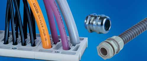
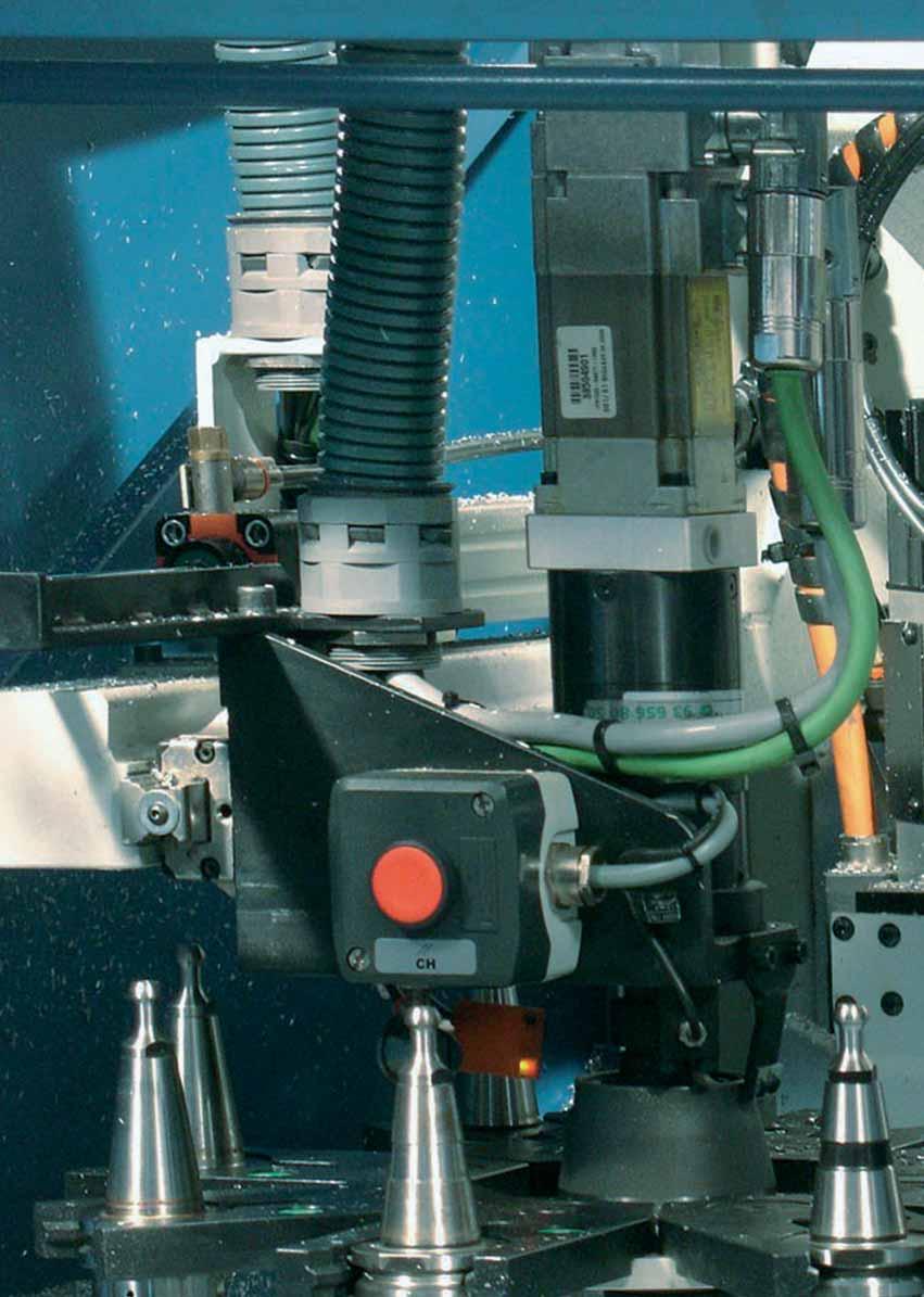
249 9. Installation accessories
250 9. Installation accessories Application Entry system Cablefix Vario, Cablefix Cable entry system for connectorized cables Plastic fittings TOP-T-P, TOP-TR-P Cable fittings with strain relief and IP rated seal Plastic accessories Locknuts GK Accessories for use with plastic fittings Reducer RR 9.11 Blanking plugs BL 9.12 Metal fittings TOP-T, TOP-TR Cable fittings with strain relief and IP rated seal TOP-T-S-EMV 1, TOP-T-S-EMV 2 Optional with shield termination Metal accessories Locknuts GMS, Locknuts GMS EMV Accessories for use with metal fittings Reducer RR, Enlarger EW Blanking plugs BLMS 9.21 Plastic and metal accessories Multiple sealing insert MFDE Sealing insert for retroactive installation in plastic and metal fitting applications 9.22 Sealing insert ASI DE 9.23 Mounting accessories Control panel installation Socket for fully protected wire connections and integrated snap connection 9.24 for simple and quick installation Cable tie For bundling of cables, conductors or conduits 9.25 Identification of hook-up wires and cables Tags for labeling of cables and conduits 9.26 Laser labels For the printing with laser printer 9.27 Marker strips Marker strips flexible and self-adhesive
251 Cable fittings and accessories Cablefix Vario Feed-through for all prefabricated cables and wires with connectors Technical data Temperature range -40 C to +135 C Burning behavior Flame-retardant Module type VG= VK= for cable and wire diameters from 4 mm to 34.5 mm, see ordering information frame sizes, see ordering information Protection class IP 65 Construction Frame AKLR from smooth ground aluminum Frame KKLR from polyamide GF50 glass fibre reinforced Modules slotted to the right from the borings Part-No. Type Dimensions (w h d) mm Unit VK/VG PU piece With flat seal and drilling template Comments Terminal frame as feed-through system with strain relief KKLR /2 1 Yes Master gauge for holes HAN 16 B attachment housing KKLR /3 1 Yes Master gauge for holes HAN 24 B attachment housing Aluminium smooth-ground, also available as anodised AKLR /1 1 Yes Hole ø 6.5 hole dimensions with flat seal AKLR /2 1 Yes AKLR /3 1 Yes AKLR /3+3 1 Yes AKLR /6 1 Yes AKLR /4 1 Yes AKLR /4+4 1 Yes AKLR /8 1 Yes AKLW /3 1 Yes Master gauge for holes HAN 24 B attachment housing Unit corresponds to the number of required rubber modules type VK or VG 9.3
252 Cable fittings and accessories Cablefix Vario Feed-through for all prefabricated cables and wires with connectors Application Electrotechnology, pneumatics, hydraulics, robotics, general machine and plant construction Properties Feed through and terminal frames from high-quality solid material Aluminium or polyamide GF50 High flexibility in the application Additional mounting to existing installation easily possible Even pressure effect on the feed through round material yields good strain relief and sealing Unneeded holes in the module can simply sealed with blank plugs Compact design i.e. space-saving 2 module sizes with slot and suspension principle Very good weatherproof resistance Resistant to UV radiation, ozone, oils, fuels, acids, bases, solvents and sea water Part-No. Type Clamping range D mm Number of holes Diameter mm Length mm Height mm suitable for Part-No. Rubber module, material TPE VK mm VK mm VK mm VK mm VK mm VK mm VK mm VK mm VK mm VK mm VK mm VG mm VG mm VG mm VG mm VG mm VG mm VG mm VG mm VG mm VG mm Matching blank plug, PA6 GF BL BL BL BL BL BL BL BL BL BL BL PU piece 9.4

253 Cable fittings and accessories Cablefix flanges ST B/V SA Application Cablefix flanges are used to introduce cables and wires into a housing. They are used in light to medium-weight machine and plant construction. Properties With the dovetail guide, the Cablefix flanges can be lined up with each other. This means that various flange combinations can be realized to suit specific requirements. Flanges can be used to suit specific requirements The integrated strain relief closes automatically when the cables and wires are pushed through. An integrated formed rubber part seals off the cables and wires by means of sealing lips. For troubleshooting, maintenance or retrofitting, the individual cables can be easily loosened from the spring clamp using a screwdriver and replaced. Unused inputs can be closed off using the plugs supplied with the product. Resistant to fuels, mineral oils, greases, alkalis Halogen- and silicone-free. Technical data Protection class IP 55 (mounting orientation from below) Temperature range -30 C to +70 C Burning behavior Flange UL 94 V2 max. metal gauge 3 mm Breakthrough with standard 46 46mm sheet metal hole punch Part-No. Type Dimensions (w h d) mm Cut-out W H mm Number of cables cable diameter Material Cablefix Control cable flange (ST) ST Flange: PA 6.6 Seal: TPE Plugs: PA 6 Retaining plates and screws: galvanised steel Cablefix Bus flange (B/V) B/V mm Note: 50 mm must be allotted for each flange mounted side by side. Flange: PA 6.6 Seal: TPE Plugs: PA 6 Retaining plates and screws: galvanised steel Cablefix Sensor/Actuator flange (S/A) S/A mm Flange: PA 6.6 Seal: TPE Plugs: PA 6 Retaining plates and screws: galvanised steel PU piece
254 Cable fittings and accessories Plastic fittings TOP-T-P, metric version Properties metric Cable fitting with hexagon base Strain relief and seal Technical data Protection class IP 68 to 5 bar Construction Material Polyamide PA 6.6-V-2 Color grey RAL 7001 black RAL 9005 Gasket Neoprene Part-No. Type G Approvals Clamping range D mm SW mm L 1 mm weight approx. kg/100 piece TOP-T-P metric grey RAL TOP-T-P M 12 1,5 M UR mm TOP-T-P M 16 1,5 M UR mm TOP-T-P M 20 1,5 M UL mm TOP-T-P M 25 1,5 M UL mm TOP-T-P M 32 1,5 M UL mm TOP-T-P M 40 1,5 M UL mm TOP-T-P M 50 1,5 M UR, UL mm TOP-T-P M 63 1,5 M UR, UL mm TOP-T-P metric black RAL TOP-T-P M 12 1,5 M UR mm TOP-T-P M 16 1,5 M UR mm TOP-T-P M 20 1,5 M UL mm TOP-T-P M 25 1,5 M UL mm TOP-T-P M 32 1,5 M UL mm TOP-T-P M 40 1,5 M UL mm TOP-T-P M 50 1,5 M UL mm TOP-T-P M 63 1,5 M mm PU piece 9.6
255 Cable fittings and accessories Plastic fittings TOP-T-P, PG version Properties PG Cable fitting with hexagon base Strain relief and seal Technical data Protection class IP 68 to 5 bar Construction Material polyamide PA 6.6-V-2 Color Grey RAL 7001 and Black RAL 9005 Gasket Neoprene Part-No. Type G Approvals Clamping range D mm SW mm L 1 mm weight approx. kg/100 piece TOP-T-P PG grey RAL TOP-T-P PG 7 PG mm TOP-T-P PG 9 PG mm TOP-T-P PG 11 PG 11 UR mm TOP-T-P PG 13,5 PG 13.5 UL mm TOP-T-P PG 16 PG 16 UL mm TOP-T-P PG 21 PG 21 UL mm TOP-T-P PG 29 PG 29 UL mm TOP-T-P PG 36 PG 36 UL mm TOP-T-P PG 42 PG 42 UL mm TOP-T-P PG 48 PG 48 UL mm TOP-T-P PG black RAL TOP-T-P PG 7 PG mm TOP-T-P PG 9 PG mm TOP-T-P PG 11 PG 11 UR mm TOP-T-P PG 13,5 PG 13.5 UL mm TOP-T-P PG 16 PG 16 UL mm TOP-T-P PG 21 PG 21 UL mm TOP-T-P PG 29 PG 29 UL mm TOP-T-P PG 36 PG 36 UL mm TOP-T-P PG 42 PG 42 UL mm TOP-T-P PG 48 PG 48 UL mm PU piece 9.7
256 Cable fittings and accessories Plastic fitting TOP-TR-P Properties Cable fitting with hexagon base Strain relief and gasket Reduced sealing insert Reduced clamping range Technical data Protection class IP 68 to 5 bar Approvals on request Construction Material Polyamide PA 6-V-2 Color grey RAL 7001 other colors upon request Gasket NBR Part-No. Type G Approvals Clamping range D mm SW mm L 1 mm weight approx. kg/100 piece TOP-TR-P metric TOP-TR-P M 16 1,5 M on request mm TOP-TR-P M 20 1,5 M on request mm TOP-TR-P M 25 1,5 M on request mm TOP-TR-P M 32 1,5 M on request mm PU piece 9.8
257 Cable fittings and accessories Plastic accessory locknut GK, metric version Properties metric Counter nut, hexagonal, with metric thread according to DIN Construction Material Polyamide 6 GF 30 Color grey RAL 7001 black RAL 9005 other color upon request Part-No. Type G SW mm S mm weight approx. kg/100 piece PU piece GK metric grey RAL GK M 12 1,5 M GK M 16 1,5 M GK M 20 1,5 M GK M 25 1,5 M GK M 32 1,5 M GK M 40 1,5 M GK M 50 1,5 M GK M 63 1,5 M GK metric black RAL GK M 12 1,5 M GK M 16 1,5 M GK M 20 1,5 M GK M 25 1,5 M GK M 32 1,5 M GK M 40 1,5 M GK M 50 1,5 M GK M 63 1,5 M
258 Cable fittings and accessories Plastic accessory locknut GK, PG version Properties PG Counter nut, hexagonal, with armour threads according to DIN Construction Material Polyamide 6 GF 30 Color grey RAL 7001 black RAL 9005 other colors available on request Part-No. Type G SW mm S mm weight approx. kg/100 piece PU piece GK PG grey RAL GK PG 7 PG GK PG 9 PG GK PG 11 PG GK PG 13,5 PG GK PG 16 PG GK PG 21 PG GK PG 29 PG GK PG 36 PG GK PG 42 PG GK PG 48 PG GK PG black RAL GK SW PG 7 PG GK SW PG 9 PG GK SW PG 11 PG GK SW PG 13,5 PG GK SW PG 16 PG GK SW PG 21 PG GK SW PG 29 PG GK SW PG 36 PG GK SW PG 42 PG GK SW PG 48 PG

259 Cable fittings and accessories Plastic accessory reducing ring RR, metric Properties -metric- Reducing ring from plastic with large outer thread and small inner thread Construction Material Polyamide PA 6 GF 30 Color Grey RAL 7035 other colors upon request Part-No. Type G G1 SW mm L mm L 1 mm weight approx. kg/100 piece PU piece RR-PA metric RR-PA M 20/M 12 M M RR-PA M 20/M 16 M M RR-PA M 25/M 12 M M RR-PA M 25/M 16 M M RR-PA M 25/M 20 M M RR-PA M 32/M 12 M M RR-PA M 32/M 16 M M RR-PA M 32/M 20 M M RR-PA M 32/M 25 M M RR-PA M 40/M 16 M M RR-PA M 40/M 20 M M RR-PA M 40/M 25 M M RR-PA M 40/M 32 M M RR-PA M 50/M 20 M M RR-PA M 50/M 25 M M RR-PA M 50/M 32 M M RR-PA M 50/M 40 M M RR-PA M 63/M 25 M M RR-PA M 63/M 32 M M RR-PA M 63/M 40 M M RR-PA M 63/M 50 M M
260 Cable fittings and accessories Plastic accessory Blank plug BL Properties Blank plug according to DIN Construction Material Polyamide PA 6 or polystyrene SB Color grey RAL 7035 other colors upon request Part-No. Type G L mm L 1 mm weight approx. kg/100 piece PU piece BL metric PA BL M 12 M BL M 16 M BL M 20 M BL M 25 M BL M 32 M BL M 40 M BL M 50 M BL M 63 M BL PG PA BL PG 7 PG BL PG 9 PG BL PG 11 PG BL PG 13,5 PG BL PG 16 PG BL PG 21 PG BL PG 29 PG BL PG 36 PG
261 Cable fittings and accessories Metal fitting TOP-T Properties Cable fitting with hexagon base Strain relief Gasket and O-Ring Technical data Protection class IP 68 to 5 bar Construction Material Brass nickel-plated Gasket Neoprene O-ring (OR) Perbunan Part-No. Type G Clamping range D mm SW 1 = across flats mm SW 2 = across flats mm L 1 mm L mm weight approx. kg/100 piece TOP-T metric TOP-T M 12 1,5 M TOP-T M 16 1,5 M TOP-T M 20 1,5 M TOP-T M 25 1,5 M TOP-T M 32 1,5 M TOP-T M 40 1,5 M TOP-T M 50 1,5 M TOP-T M 63 1,5 M TOP-T PG TOP-T PG 7 PG TOP-T PG 9 PG TOP-T PG 11 PG TOP-T PG 13,5 PG TOP-T PG 16 PG TOP-T PG 21 PG TOP-T PG 29 PG TOP-T PG 36 PG TOP-T PG 42 PG TOP-T PG 48 PG PU piece 9.13
262 Cable fittings and accessories Metal fitting TOP-TR Properties Cable fitting with hexagon base Strain relief Gasket and O-Ring Reduced sealing insert Reduced Clamping range Technical data Protection class IP 68 to 5 bar Construction Material Brass nickel-plated Gasket Neoprene O-ring (OR) Perbunan Part-No. Type G Clamping range SW 1 = across D mm flats mm SW 2 = across flats mm L 1 mm L mm weight approx. kg/100 piece TOP-TR metric TOP-TR M 12 1,5 M TOP-TR M 16 1,5 M TOP-TR M 20 1,5 M TOP-TR M 25 1,5 M TOP-TR M 32 1,5 M TOP-TR M 40 1,5 M TOP-TR M 50 1,5 M TOP-TR M 63 1,5 M PU piece 9.14

263 Cable fittings and accessories Metal fitting with shield termination TOP-T-S-EMV1 Properties Cable fitting with hexagon base Strain relief Gasket O-ring and EMC compliant shield termination For installation, the shield braiding and plastic insert are pressed against fitting base. Technical data Protection class IP 68 to 5 bar Construction Material Brass nickel-plated Gasket Neoprene O-ring (OR) Perbunan Part-No. Type G Clamping range D mm TOP-T-S-EMV1 metric TOP-T-S-EMV1 M 12 1, TOP-T-S-EMV1 M 16 1, TOP-T-S-EMV1 M 20 1, TOP-T-S-EMV1 M 25 1, TOP-T-S-EMV1 M 32 1, TOP-T-S-EMV1 M 40 1, TOP-T-S-EMV1 M 50 1, TOP-T-S-EMV1 M 63 1,5 SW mm L 1 mm d mm weight approx. kg/100 piece M M M M M M M M TOP-T-S-EMV1 PG TOP-T-S-EMV1 PG 7 PG TOP-T-S-EMV1 PG 9 PG TOP-T-S-EMV1 PG 11 PG TOP-T-S-EMV1 PG PG , TOP-T-S-EMV1 PG 16 PG TOP-T-S-EMV1 PG 21 PG TOP-T-S-EMV1 PG 29 PG TOP-T-S-EMV1 PG 36 PG TOP-T-S-EMV1 PG 42 PG TOP-T-S-EMV1 PG 48 PG PU piece 9.15

264 Cable fittings and accessories Metal fitting with shield termination TOP-T-S-EMV2 Properties Cable fitting with hexagon base Strain relief Gasket O-ring and EMC compliant shield termination The braided shield is automatically contacted when mounting the screw connection. Technical data Protection class IP 68 to 5 bar, 30 Min. Construction Material Brass nickel-plated Gasket Neoprene O-ring (OR) Perbunan Part-No. Type G Clamping range SW 1 = across D mm flats mm TOP-T-S-EMV2 metric TOP-T-S-EMV2 M 12 1, TOP-T-S-EMV2 M 16 1, TOP-T-S-EMV2 M 20 1, TOP-T-S-EMV2 M 25 1, TOP-T-S-EMV2 M 32 1, TOP-T-S-EMV2 M 40 1, TOP-T-S-EMV2 M 50 1, TOP-T-S-EMV2 M 63 1,5 SW 2 = across flats mm L 1 mm L mm weight approx. kg/100 piece M M M M M M M M PU piece 9.16
265 Cable fittings and accessories Metal accessory Locknut GMS Properties Counter nut according to DIN 46320, hexagonal Construction Material Brass nickel-plated Part-No. Type G SW mm S mm weight approx. kg/100 piece PU piece GMS metric GMS M M GMS M M GMS M M GMS M M GMS M M GMS M M GMS M M GMS M M GMS PG GMS PG 7 PG GMS PG 9 PG GMS PG 11 PG GMS PG 13.5 PG GMS PG 16 PG GMS PG 21 PG GMS PG 29 PG GMS PG 36 PG GMS PG 42 PG GMS PG 48 PG
266 Cable fittings and accessories Metal accessory Locknut GMS EMC Properties Hexagonal nut for potential equalisation With cutting edges for cutting through layers of paint or power coating for optimal contact Construction Material Brass nickel-plated Part-No. Type G SW mm S1 mm S2 mm weight approx. kg/100 piece PU piece GMS EMV metric GMS EMV M M GMS EMV M M GMS EMV M M GMS EMV M M GMS EMV M M GMS EMV M M GMS EMV M M GMS EMV M M GMS EMV PG GMS EMV PG 7 PG GMS EMV PG 9 PG GMS EMV PG 11 PG GMS EMV PG 13.5 PG GMS EMV PG 16 PG GMS EMV PG 21 PG GMS EMV PG 29 PG GMS EMV PG 36 PG GMS EMV PG 42 PG GMS EMC PG 48 PG

267 Cable fittings and accessories Metal accessory reducing ring RR Ø Properties Reducing ring from metric to metric or PG to PG with large outer thread and small inner thread Construction Material Brass nickel-plated Part-No. Type G G1 Outer mm L mm L 1 mm weight approx. kg/100 piece PU piece RR metric metric/metric RR M 16/M 12 M M RR M 20/M 12 M M RR M 20/M 16 M M RR M 25/M 16 M M RR M 25/M 20 M M RR M 32/M 20 M M RR M 32/M 25 M M RR M 40/M 25 M M RR M 40/M 32 M M RR M 50/M 32 M M RR M 50/M 40 M M RR M 63/M 40 M M RR M 63/M 50 M M RR PG PG/PG RR PG 9/PG 7 PG 9 PG RR PG 11/PG 7 PG 11 PG RR PG 11/PG 9 PG 11 PG RR PG 13.5/PG 9 PG 13.5 PG RR PG 13.5/PG 11 PG 13.5 PG RR PG 16/PG 9 PG 16 PG RR PG 16/PG 11 PG 16 PG RR PG 16/PG 13.5 PG 16 PG RR PG 21/PG 11 PG 21 PG RR PG 21/PG 13.5 PG 21 PG RR PG 21/PG 16 PG 21 PG RR PG 29/PG 16 PG 29 PG RR PG 29/PG 21 PG 29 PG RR PG 36/PG 21 PG 36 PG RR PG 36/PG 29 PG 36 PG RR PG 42/PG 36 PG 42 PG RR PG 48/PG 36 PG 48 PG RR PG 48/PG 42 PG 48 PG

268 Cable fittings and accessories Metal accessory expansion EW Properties Expansion from metric to metric or PG to PG with small outer thread and large inner thread Construction Material Brass nickel-plated Ø Part-No. Type G G1 Outer mm L mm L 1 mm weight approx. kg/100 piece PU piece EW metric metric/metric EW M 12/M 16 M M EW M 16/M 20 M M EW M 20/M 25 M M EW M 25/M 32 M M EW M 32/M 40 M M EW M 40/M 50 M M EW M 50/M 63 M M EW PG PG/PG EW PG 7/PG 9 PG 7 PG EW PG 9/PG 11 PG 9 PG EW PG 11/PG 13.5 PG 9 PG EW PG 11/PG 13.5 PG 11 PG EW PG 11/PG 16 PG 11 PG EW PG 13.5/PG 16 PG 13.5 PG EW PG 13.5/PG 21 PG 13.5 PG EW PG 16/PG 21 PG 16 PG EW PG 21/PG 29 PG 21 PG EW PG 29/PG 36 PG 29 PG EW PG 36/PG 42 PG 36 PG EW PG 42/PG 48 PG 42 PG

269 Cable fittings and accessories Metal accessory blank plug BLMS Properties Blank plug according to DIN Construction Material Brass nickel-plated Part-No. Type G L mm L 1 mm weight approx. kg/100 piece PU piece BLMS metric BLMS M 12 M BLMS M 16 M BLMS M 20 M BLMS M 25 M BLMS M 32 M BLMS M 40 M BLMS M 50 M BLMS M 63 M BLMS metr. with O ring BLMS M 12 M BLMS M 16 M BLMS M 20 M BLMS M 25 M BLMS M 32 M BLMS M 40 M BLMS M 50 M BLMS M 63 M BLMS PG BLMS PG 7 PG BLMS PG 9 PG BLMS PG 11 PG BLMS PG 13.5 PG BLMS PG 16 PG BLMS PG 21 PG BLMS PG 29 PG BLMS PG 36 PG
270 Cable fittings and accessories Plastic and metal accessory multiple sealing insert MFDE Application For retroactive installation in our cable fittings Type Top T in plastic and brass, if necessary these are to be drilled yourself depending on needs PG 11 suitable for M 16 PG 13.5 suitable for M 20 PG 16 suitable for M 25 PG 21 suitable for M 32 Properties Multiple sealing insert for two or more cables in a fitting Construction Material TPE Part-No. Type Outer mm Number of cables mm weight approx. kg/100 piece PU piece MFDE PG MFDE PG MFDE PG MFDE PG MFDE PG MFDE PG MFDE PG MFDE PG MFDE PG MFDE PG MFDE PG MFDE PG MFDE PG MFDE PG MFDE PG MFDE PG MFDE PG MFDE PG MFDE PG MFDE PG MFDE PG MFDE PG MFDE PG MFDE PG MFDE PG MFDE PG MFDE PG MFDE PG MFDE PG MFDE PG MFDE PG MFDE PG MFDE PG MFDE PG MFDE PG MFDE PG MFDE PG

271 Cable fittings and accessories Plastic and metal accessory sealing insert ASI DE Application For retroactive installation of our cable fittings Cable dimensions: 4.0 mm 10.0 mm +/- 0.2 mm Suitable for installation with the following types: TOP TP PG 13.5 TOP TP M 20 TOP T PG 13.5 TOP T M 20 Properties Seal insert for ASI bus cables Construction Material TPE Part-No. Type Outer mm weight approx. kg/100 piece PU piece ASI DE ASI DE PG

272 Mounting accessories and tools Control panel installation Properties The developed snap-fit socket with fully-protected wire connections and integrated snap connection enables a simple and quick installation in the control cabinet. Part-No. Type Description Nominal voltage range Number of terminations Voltage V Color weight approx. kg/100 piece Socket ST-3/S ST-3/S GR Socket ST -3/S DC 10A / AC 16A grey ST-3/S Socket ST -3/S DC 10A / AC 16A yellow Socket ST-3/A ST-3/A GR Socket ST-3/A with switch indicator (green glow lamp) DC 10A / AC 16A grey Socket ST-3/F ST-3/F Socket ST-3/F DC 10A / AC 16A grey French construction Adapter ST3/SEV-TYP 13/23 Adapter ST3/SEV Type 13, suitable for ST-3/S, ST-3/A, ST-3/4. DC 10A / AC 16A grey PU piece 9.24

273 Mounting accessories and tools Cable tie Application Cable ties fast and simple installation For the bundling, binding and attaching of cables, conductors, braids, wires and conduit. Nondetachable! Technical data Temperature range -10 C to +85 C Construction Material Polyamide KSN = mold-resistant; KSS = UV-resistant Color natural, black Part-No. Type Color Width mm bundling range to approx.... mm weight approx. kg/100 piece PU piece cable tie KSN KSN 1 natural KSN 2 natural KSN 3 natural Cable tie KSS KSS 1 black KSS 2 black KSS 3 black KSS 4 black


274 Labelling system Identification of hook-up wires and cables Technical data Temperature range -30 C to +80 C Stability UV-stable and non-yellowing KS1 Construction Material Polypropylene Coverage cap: Polystyrene Part-No. Type Description Dimensions mm weight approx. kg/100 piece PU piece Clip markers CS 1/CS CS 1 For labelling of devices and supply cables after the wiring. Termination area 0.75 to 4.0 mm clip-on markers are supplied with labelling sheets. Labelling sheets for laser printer see system for laser printer labelling CS 2 For labelling of devices and supply cables after the wiring. Termination area 0.75 to 4.0 mm clip-on markers are supplied with labelling sheets. Labelling sheets for laser printer see system for laser printer labelling Cable marker KS KS 1 The cable marker KS 1 is designed for the labelling of cables, wires and conduits, pipes etc. in raw, damp and dusty environments. The label with the information is embedded in the cable marker and thus fully protected. The marker is attached using cable ties. (not included in the scope of delivery, when ordering the cable tie, selected the appropriate size.) Cable markers are supplied with labelling sheets. Labelling sheets for laser printer see system for laser printer labelling Plug-in marker SS SS 2 For the labelling of devices on the mounting panel. Hole 4 mm. Pressing in of the plug-in marker. Securely locked in by plastic lugs. Plug-in markers are supplied with labelling sheets. labelling sheets see system for laser printer labelling Labels on sheets, endless form BS-CS 1 Labelling sheet for CS BS-CS 2 Labelling sheet for CS
275 Labelling system Laser labels Application For the printing with laser printer The high-contrast printing and the high resolution of laser printers set quality standards The available border and the appropriate row and column spacing enable the optimal utilisation of the entire labelling field of the self-adhesive labels Very high resistance to external influences and very high ageing resistance of the printed image. Construction Material Polyester white matte Dimension 0.05 mm Part-No. Type Description Dimensions mm Label/Sheet Laser labels BSL-CS 1 Labels for clip on markers CS BSL-SS 2 Labels for identification of hook-up wires and cables CS 2, SS 2 and KS Self-adhesive laser labels LEB 0920 PW Labels suitable for: marker holder BZT 0920 MINICOMPACT DIOFACE valve plug all devices with standard marker LEB 0615 PW Labels suitable for: marker holder BZT 0720 MINICOMPACT modules 12.5 mm Actuator sensor boxes DIOPLEX LEB 0415 PW Labels suitable for: marker holder BZT 0411 MICROCOMPACT modules 6.2 mm

276 Labelling system Marker strips Application Marker strips flexible and self-adhesive For the labelling of cable channels, control panels, operator panels.. The labelled inserts are protected by a transparent film Transparent hard film with exchangeable case strips for self-labelling Can be cut to any desired length Film and labelling strips are supplied separately Part-No. Type Description PU piece Marker strip BS BS Width Length: 21.5 mm 1000 mm max. Labelling surface area: 18.0 mm 1000 mm
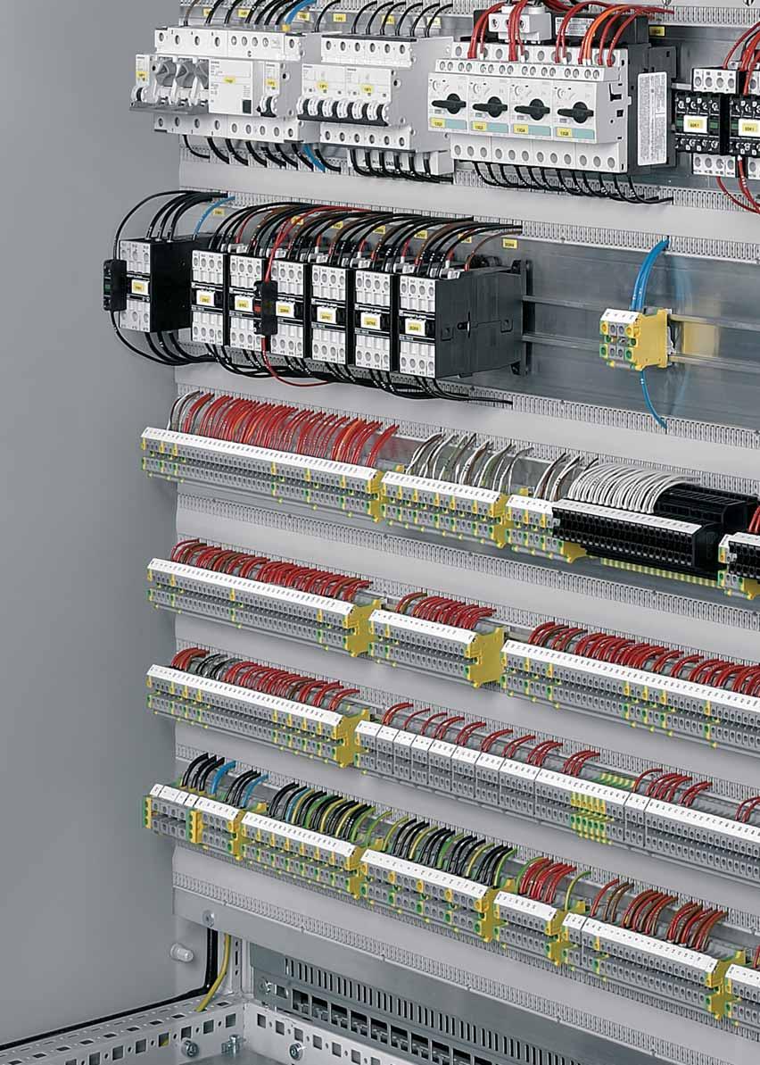
277 10. EMC accessories


278 10. EMC accessories EMC shield rails Page and accessories EMC shield clamps and accessories Earthing strips Cable clips More Informations about cabinet wiring with LÜTZE LSC AirSTREAM: and
 1.")
279 EMC accessories EMC shield rail EMC shield rail EMC shield rail with cable clamping options for a wide variety of shield clamps Description Part-No. Type PU EMC shield rail EMVS Dimensions Technical data Number of shield points 46 Length mm Height 75.0 mm Width 21.5 mm Weight (kg/piece) General Material ST37-2-G Surface burr-free Color sendzimier-zinc-plated μm Storage temperature range -30 C 90 C Operation temperature range -5 C 80 C usable shield clamps for cable mm Type Article number PU Shield clamp 0 12 EMVSK spring shield clamp EMVFSK spring shield clamp EMVFSK spring shield clamp EMVFSK Metal tie wrap 250 mm lengh KSE as clamping option for cable mm Type Article number PU Cable clamp 8 12 KS Cable clamp KS Cable clamp KS Cable clamp KS Cable clamp KS Comments Mounting hole, diam. 8.5 mm, is made by the user. Shield rails are mounted via spacing rollers DR 20 18/8.5 Article no possible screw M8 30, Article no
 18.0 80.0 65.")
 Surface smooth Color Punched edges bare/bright galvanised Storage temperature range -30 C 90")
280 EMC accessories Mounting bracket Mounting bracket Mounting bracket for fastening the EMC rail in the control cabinet Description Part-No. Type PU Mounting bracket HW-EMVS 03 2 Dimensions Technical data Dimensions (w h d) mm Material thickness 3 mm Thread 2 M8 Hole diameter mm weight approx kg/100 piece General Material S235JR (ST37-2) Surface smooth Color Punched edges bare/bright galvanised Storage temperature range -30 C 90 C Operation temperature range -5 C 80 C Comments suitable for shield rail
 32.0 15.0 1155.0 mm weight approx. 0.47 kg/100 piece Hole diameter 5.")
281 EMC accessories EMC shield rail EMC shield rail EMC shield rail with cable clamping options for a wide variety of shield clamps Description Part-No. Type PU EMC shield rail EMVS Dimensions Technical data Number of shield points max. 55 Dimensions (w h d) mm weight approx kg/100 piece Hole diameter 5.3 mm General Material Sheet steel Surface galvanised Color Punched edges bare/natural Storage temperature range -30 C 90 C Operation temperature range -5 C 80 C Accessories Article number Type PU Bracket HW EMVS

282 EMC accessories Bracket Bracket Retaining bracket for fastening the EMC rail Description Part-No. Type PU Bracket HW-EMVS Dimensions Technical data Dimensions (w h d) mm Material thickness 1.5 mm Thread M5 Hole diameter weight approx. kg/100 piece General Material V2A Surface smooth Color Punched edges bare/natural Storage temperature range -30 C 90 C Operation temperature range -5 C 80 C Comments suitable for shield rail

283 EMC accessories Shield clamp Shield clamp Description Part-No. Type PU Shield clamp EMVSK Shield clamp Dimensions Technical data For cable diameter 0 12 mm weight approx kg/100 piece General Material Federstahl Material thickness 0.3 mm Surface smooth/burr-free Color bare/stainless Operation temperature range 0 C 60 C Accessories Article number Type PU Special pliers ZSD
284 EMC accessories Spring shield clamp Spring shield clamp Shield connection for large-diameter cables Description Part-No. Type PU Spring shield clamp EMVFSK EMVFSK EMVFSK 3 10 Dimensions Technical data For cable diameter mm mm mm Length mm mm mm weight approx kg/100 piece 0.50 kg/100 piece 0.70 kg/100 piece Tensile strength (N/mm²) General Material Spring steel Color bare/stainless Operation temperature range 0 C 60 C 10.8

285 EMC accessories Snap-on element Snap-on element for snapping onto hat rail for attaching a screening clamp Dimensions Description Part-No. Type PU Snap-on element Length mm EMVRE H 1 10 Technical data weight approx kg/100 piece General Material Spring steel Color bare/stainless Operation temperature range -20 C 60 C Comments Suitable for all crosspieces and hat profile TS35 Application example 10.9

286 EMC accessories Snap-on element can be snapped onto LSC profiles Description Part-No. Type PU Snap-on element Length mm EMVRE mm EMVRE 2 10 Dimensions Technical data weight approx kg/100 piece 1.80 kg/100 piece General Material Sheet steel Color bare/stainless Operation temperature range 0 C 60 C Comments suitable for all webs of the series M, S, SN, MF, F, A Application example 10.10
287 EMC accessories Ribbon cable earthing device Earthing strip, copper braiding, tin-plated Single wire Cu ETP UNI , similar to DIN Description Part-No. Type PU both ends drilled, cold pressed Cross section EMVMB 10/100/ EMVMB 10/200/ EMVMB 16/200/ EMVMB 25/200/10 10 Dimensions Technical data Wire conductors 0.15 mm 2 D 6.5 mm 8.5 mm 10.5 mm A 22.0 mm 25.0 mm B 12.0 mm 15.0 mm 23.0 mm Weight (kg/m) Approvals UL E L mm mm General Amperage range see standards table (e.g. EN 60204) Cable construction individual conductor braided; cross-section rectangular Storage temperature range -30 C 90 C Operation temperature range 5 C 105 C Accessories Article number Type PU Earthing set ES 8 1 Earthing set ES 6 1 Comments D= hole diameter A= sleeve length B= width L= distance of hole Other lengths are available on request 10.11

288 EMC accessories Ribbon cable earthing device Earthing strip, copper braiding, tin-plated Single wire Cu ETP UNI , similar to DIN Description Part-No. Type PU both ends drilled, cold pressed Cross section EMVMB 10/300/M EMVMB 16/300/ EMVMB 25/300/ EMVMB 16/500/8 10 Dimensions Technical data Wire conductors 0.15 mm 2 D 6.5 mm 8.5 mm 10.5 mm 8.5 mm A 22.0 mm 25.0 mm B 12.0 mm 15.0 mm 23.0 mm 15.0 mm Weight (kg/m) Approvals UL E L mm mm General Amperage range see standards table (e.g. EN 60204) Cable construction individual conductor braided; cross-section rectangular Storage temperature range -30 C 90 C Operation temperature range 5 C 105 C Accessories Article number Type PU Earthing set ES 8 1 Earthing set ES 6 1 Comments D= hole diameter A= sleeve length B= width L= distance of hole Other lengths are available on request 10.12

289 EMC accessories Cable clip Cable clip Description Part-No. Type PU Cable clip KS KS KS KS KS 4 10 Cable clip Dimensions Technical data weight approx kg/100 piece 3.20 kg/100 piece 3.50 kg/100 piece 6.80 kg/100 piece 6.00 kg/100 piece Thread M6 M8 General Material steel Color galvanised Operation temperature range 0 C 60 C Hexagon screw slotted Accessories Article number Type PU can be used on Lütze rails EMVS 03 can be used on Lütze rails EMVS 04 can be used on Lütze rails C rail Comments Sold only with counter-shell, polypropylene plastic 10.13
290 Notes 10.14
 11.11 Current loads 11.12 Conductor resistances 11.14 Voltages per DIN VDE 0298 T1 / IEC 183 11.15 Conductor structure acc.")

291 11. Technical information Bending cycles of high flexing cables 11.4 Motor, servo and inverter applications 11.5 Bus and network cables 11.6 ETHERNET - Overview 11.7 Approvals in North America 11.9 NFPA Ampacity per National Electric Code (USA) Current loads Conductor resistances Voltages per DIN VDE 0298 T1 / IEC Conductor structure acc. DIN VDE 0295/IEC and AWG Conductor labelling according to DIN in pairs Colour code tables Chemical resistance of PVC, TPE and PUR cable jackets Properties of isolation materials Bend radii for fixed installation Torques for cable fittings Design of the protection class designation according to EN Short abbreviation key according to VDE and DIN Technical Terms The price of copper Conditions fot the relinquishment of cable and wire spools Certificates 11.29
 and allows easy installation LÜTZE SILFLEX is available as control or power cable configurations.")

292 LÜTZE SILFLEX LÜTZE SILFLEX - The flexible cable for harsh industrial environments LÜTZE SILFLEX is a cable for flexible applications without compulsory guide (not recommended for drag chains) and allows easy installation LÜTZE SILFLEX is available as control or power cable configurations. The offering includes besides the Standard PVC type options with UL and VDE approval and also halogen free versions with PUR jacket for harsh industrial environments LÜTZE SILFLEX can be used in machine and plant construction, conveyor systems, Industrial HVAC as well as many other industrial applications. LÜTZE SILFLEX cables are silicone free and are being used by many automotive plants in various different applications. 11.2

 insulation and with specially formulated PVC jacket.")
293 LÜTZE SUPERFLEX and LÜTZE SUPERFLEX PLUS LÜTZE SUPERFLEX sets Industry standards: longevity, reliability, flexibility LÜTZE offers a variety of high flexing cables specifically designed for use in continuous motion applications such as drag chains. LÜTZE SUPERFLEX and LÜTZE SUPERFLEX Plus cables include high flexing control and motor supply cables, as well as electronic and network cables. All LÜTZE SUPERFLEX cables are compatible with all major brand drag chains. LÜTZE SUPERFLEX N is designed for moderate to higher performance flexing in short to medium length drag chains. LÜTZE SUPERFLEX N is offered with PVC or High Glide Insulation (TPE) insulation and with specially formulated PVC jacket. LÜTZE SUPERFLEX Plus PUR is designed for high performance flexing or longer drag chains. LÜTZE SUPERFLEX Plus PUR contains high grade premium materials such as High Glide TPE insulation and PUR jackets for high performance applications in modern high speed machine tools. All high flexing cables require special handling and installation techniques which are different from those of standard flexible control cables. To ensure the longest possible life span for your cable, it is important to follow installation procedures precisely. Find here more informations about LÜTZE SUPERFLEX
294 Bending cycles of high flexing cables LÜTZE SUPERFLEX - longevity, reliability, flexibility The high mechanical requirements in a drag chain require the use of special cables, which are designed for the usage in continuous motion application. The life span of cable in drag chains is strongly influenced by mechanical parameters of the application, as well as the carefulness of the installation. Type of cable Traveling distance Bending radius = Velocity Acceleration Cycles in m Factor x Cable-Ø (mm) m/s m/s 2 mio. LÜTZE SUPERFLEX PLUS Unshielded cable with 5 10 Ø special TPE or HGI 20 7,5 Ø insulation, PUR or TPE jacket 100 7,5 Ø LÜTZE SUPERFLEX PLUS (C) Shielded cable with 5 12 Ø special TPE or HGI Ø insulation, PUR or TPE jacket Ø LÜTZE SUPERFLEX Unshielded cable 5 12 Ø Ø LÜTZE SUPERFLEX (C) Shielded cable 5 15 Ø Ø The values of this table show application-parameter and actual performed cycles in independent tests. The cycle count can only be compared, if every value is taken in consideration with each other. A valuation as Million Operating Cycles is insignificant, if traveling distance, velocity and bending radius is unknown. LÜTZE SUPERFLEX PLUS M (C) PUR UL Servo 0,6 / 1 kv according to SIEMENS* Standard Similar to SIEMENS MOTION-CONNECT 800PLUS LÜTZE SUPERFLEX PLUS M (C) PUR UL Servo 0,6 / 1 kv Traveling distance Bending radius = Velocity Acceleration Cycles in m Factor x Cable-Ø (mm) m/s m/s 2 mio Ø Ø Ø Ø Ø
 PVC 0,6/1 kv cables with PVC Insulation.")

295 Motor, servo and inverter applications LÜTZE offers a wide offering of cables especially designed for motor supply applications Standard LÜTZE SILFLEX M (C) PVC 0,6/1 kv For the standard motor supply application we recommend the use of our LÜTZE SILFLEX M PVC 0,6/1 kv or the shielded LÜTZE SILFLEX M (C) PVC 0,6/1 kv cables with PVC Insulation. These cables offer a high level of safety due to their higher voltage rating. This construction offers also high flexibility and an easy strip jacket and thus is ideal for field installation or routing to the machine. Servo and Frequency Converter LÜTZE SILFLEX M (C) PVC UL SERVO 0,6/1 kv LÜTZE SUPERFLEX PLUS M (C) PUR UL SERVO 0,6/1 kv For any motor supply application with a Servo or Variable Frequency Drive we recommend our special design 0.6/1kV cables with TPM- or LÜTZE High Glide Insulation (HGI) based on Polypropylene. These cables have a lower capacitance and improved voltage breakthrough resistance. For fixed or flexible use we offer LÜTZE SILFLEX M (C) PVC UL SERVO 0,6/1 kv which also meets the Siemens 6FX5008 Standard. For use in continuous flexing applications, such as drag chains, there is a large variety of LÜTZE SUPERFLEX PLUS M (C) PUR UL SERVO 0,6/1 kv cables in many different configurations covering many different Servo applications. LÜTZE SUPERFLEX PLUS are found in many machine tools as well as automobile manufacturing because of their proven reliability. Variable Frequency Drives (Frequency converter) LÜTZE SILFLEX B XLPE 3 (C) PVC 0,6/1 kv When the cable run from the VFD to the motor is long, the right cable design matters! Cross linked Polyethylene is currently the best option as insulation material for this application, because this material offers very low capacitance and high impedance. LÜTZE SILFLEX B XLPE 3 (C) PVC 0,6/1 kv also has an optimized symmetrical construction to reduce stray currents. A-symmetrical design with one full size ground Symmetrical design with 3 grounds If electrical induction motors are controlled by a variable frequency drive, some voltage spikes can be induced in the motor shaft or motor housing. When this voltage overcomes the oil films resistance and enters the motor bearings it can lead to premature bearing failure. A symmetrical construction can improve the situation as it reduces the magnetic field and therefore the likelihood to induce voltage. Another important point is the temperature rating of the cable. The better the temperature resistance of the material the more efficient can the cable transmit power. LÜTZE SILFLEX B XLPE 3 (C) PVC 0,6/1 kv is setting a high standard with a temperature rating of 90 C for the insulation and the jacket. 11.5

296 Bus and network cables Profibus Fast Connect These cables have an optimized radial, symmetrical construction and can facilitate the application of special tools. Thereby, bus connector plugs are able to be assembled in a fast and installation-friendly way. CAN-Bus Can-Bus is specified according to ISO Primarily designed for automotive applications Can-Buses are used today for the exchange of digital information, Controller Area Network (CAN) for faster data transfer/data exchange. Bus- and Network cables Bus-Systems have become a very vital part of factory automation and it s hard to imagine automation without it. Besides hardware and software components, passive components such as bus cables and connectors play an important role for reliable function of the system. Bus cables must comply with all electrical parameters of the particular system. There is no universally applicable bus cable as the individual requirements are to diverse. LÜTZE offers robust, industrial grade Bus- and Network cables for the most common used systems worldwide. These cables are being offered for fixed and flexible application as well as continuous moving application in drag chains. Applications ASI - Actuator-Sensor-Interface The AS-Interface per EN is a serial Actuator Sensor Network being used for digital signals in the lower field levels. It works in accordance to the Master Slave Principle and presents a cost effective alternative to other serial bus systems. Profibus Profibus ist he most common Bus-System used in Europe in the area of automated manufacturing. Profibus PA The engineering of these cables per IEC fulfills the requirements in process automation and also offers intrinsically safe connection to the field devices. Profibus PA is a synchronous protocol with DC-current flow free transmission, which is also often designated as H1. The IEC Technique is applied at the PROFIBUS-PA. Profibus DP This Profibus variant, optimized through increased transmission speed and low installation cost, was especially designed for the communication between automation systems and decentralized peripheral devices in the field range. Profibus-DP substitutes the conventional parallel data communication with 24V or 0-20 ma. Lütze Profibus cables meet the specification for Profibus-DP type A according to EN Profibus-DP und Profibus FMS use the same transmission technology as well as a unified Bus protocol. Both variants can be operated simultaneously on one cable. Interbus The Interbus-S was published in 1987 as an open sensor/ actuator bus protocol. As a typical sensor/actuator fieldbus, it is configured for the cyclic processing of process data and hence differentiates significantly from data orientated field buses. The main application area of Interbus-S lays in production engineering,, process engineering, as well as transport and logistics. Here the main focus is both the automotive industry and the drive technology. DeviceNet DeviceNet is a service related Network, based on the proven CAN-Technology for fast data exchange. The configuration consists of thick cable (aka Trunk cable) and thin cable (aka drop cable). The use of high flexing cables in drag chains is likewise possible. DeviceNet has been standardized by Open DeviceNet Vendor Association (ODVA) and is the leading bus system for industrial automation in North America. Industrial Ethernet Ethernet ist the most commonly used communication technology. The Ethernet Standard allows for a remarkable increase in the bandwidth, from 12 Mbits/s for a bus system, to up to 10 Gbit/s. In the office world the Ethernet Standard has already established itself as the standard technology, however the requirements for wiring systems and active components in the industrial environment differ greatly from those in an office environment. On one hand the infrastructure must be more robust; and on the other hand criteria such as real time application require special IT solutions. Consequently, this has resulted in the development of various proprietary systems such as ProfiNet, EtherCAT, Modbus TCP and Powerlink with system specific components which may not be compatible with others. A structured Ethernet cabling according to EN should support each proprietary system. While LÜTZE offers a large number of industrial Ethernet cable solutions we are pleased to have a special innovation with our drag chain suitable Cat6 Ethernet cable. 11.6
")

297 ETHERNET Overview 1. Correct Handling and Installation of Network Copper Cable Do not subject cable to tension Do not kink the cable Do not bend the cable more than 90º (See individual specifications for bending radius) Strip the cable as short as possible Do not crush cable when fastening Do not untwist the conductor pairs by more than 0.5 inch Terminate the shielding on both ends 2. LÜTZE ETHERNET Cables We recommend shielded industrial Ethernet cable, such as LÜTZE ETHERNET cable, for use in industrial environment to ensure secure connectivity. Motors and other electrical noise producing devices are often located in close proximity to network cabling. EMI (Electro Magnetic Interference) and RFI (Radio Frequency Interference) can distort data transmission on copper-based network cable. To lessen or eliminate interference, called alien-crosstalk, the use of shielded industrial cable and connectors is recommended. Available LÜTZE ETHERNET Cables: S/UTP SF/UTP SF/UTQ (Star Quad) S/FTP Susceptibility for Interference some low low low CAT 5e CAT 5e CAT CAT 6a CAT 5e CAT CAT 7a CAT6e CAT CAT 5 3. Key for twisted pair cables according to ISO/IEC (2002)E XX/YZZ XX outer jacket / Y for the pair shielding ZZ wire paring U = unshielded / U = unshielded TP = twisted pair (regular) F = foiled shield / F = foiled shield TQ = quad pair (star quad) S = braided shield / S = braided shield SF = braided and foiled shield In order to utilize EMI/RFI shielding, the shield must be properly terminated at both ends! 11.7

298 ETHERNET Overview 4. ProfiNet Star Quad Design and Termination The star quad is a specific low-impedance cable configuration. Four conductors are twisted on a common axis. The conductors across from each other make a pair. In Figure 1 the pairs are as follows: Pair 1: Conductor A Pair 2: Conductor B Conductor D Conductor C Other terminations than in Figure 1 lead to interferences, decreased connectivity or no connectivity at all. Figure 1 5. Pin Assignment and Installation RJ45 is the most common Ethernet connector and is available both shielded and unshielded. All pins of the RJ45 connector are used for 1000 Mbit/s (4-pair transmission). Four pins are used for 10/100 Mbit/s (2-pair transmission). According to the EN standard, two color codes are defined for installation: T568A and T568B. It makes no difference which color code is used, however the same code should be used consistently throughout the entire installation. Mixing up the two color codes will result in malfunctions. Pin assignement RJ45 Color code according to EN hard wiring: ETHERNET cables Star Quad (ProfiNet) Paired Pin# 100BASE-TX Colorcode 10 BASE-T, 100BASE-TX 1000BASE-T Colorcode T568A Colorcode T568B 1 Transmit+ yellow Transmit+ BI_DA+ (bidirectional) WH/GN WH/OR 2 Transmit- orange Transmit- BI_DA- (bidirectional) GN OR 3 Receive+ white Receive+ BI_DB+ (bidirectional) WH/OR WH/GN 4 BI_DC+ (bidirectional) BL BL 5 BI_DC- (bidirectional) WH/BL WH/BL 6 Receive- blue Receive- Bl_DB- (bidirectional) OR GN 7 Bl_DD+ (bidirectional) WH/BN WH/BN 8 BI_DD- (bidirectional) BN BN 6. ETHERNET Categories and Classes ProfiNet CAT 5 CAT 5e CAT 6 CAT 6a CAT 7 Class D D De E Ea F Construction 2 pair 2 pair 4 pair 4 pair 4 pair 4 pair (AWG 22) (AWG 24, AWG 26) (AWG 24, AWG 26) (26 AWG) (26 AWG) (26 AWG) Speed 10/100 10/100 10/100/ /100/ /100/1000/ /100/1000/10000 Mbit/s Mbit/s Mbit/s Mbit/s Mbit/s Mbit/s LAN 10BASE-T (2 pair) 10BASE-T (2 pair) 10BASE-T (2 pair) 10BASE-T 10BASE-T 10BASE-T Applications 100BASE-TX (2 pair) 100BASE-TX (2 pair) 100BASE-TX (2 pair) 100BASE-TX 100BASE-TX 100BASE-TX (max.) 1000BASE-T (4 pair) 1000BASE-T 1000BASE-T 1000BASE-T 10BASE-T 10GBASE-T 10GBASE-T Nominal 100 Ohm 100 Ohm 100 Ohm 100 Ohm 100 Ohm 100 Ohm Impedance Bandwidth 100 MHz 100 MHz 100 MHz 250 MHz 500 MHz 600 MHz max. lenght 100 m (10BASE-T) 100 m (10BASE-T) 100 m (10BASE-T) 100 m (10BASE-T) 100 m (10BASE-T) 100 m (10BASE-T) 100 m (100BASE-TX) 100 m (100BASE-TX) 100 m (100BASE-TX) 100 m (100BASE-TX) 100 m (100BASE-TX) 100 m (100BASE-TX) 100 m (1000BASE-T) 100 m (1000BASE-T) 100 m (1000BASE-T) 100 m (1000BASE-T) 100 m (10GBASE-T) 100 m (10GBASE-T) CAT CAT 5 CAT 5 CAT 5 CAT 5, CAT 5e CAT 5, CAT 6 CAT 5, CAT 6, compatibility CAT 6a ISO/IEC ISO/IEC ISO/IEC ISO/IEC Modification 1 ISO/IEC standard ISO/IEC ANSI/TIA ANSI/TIA-568-B ANSI/TIA-568-C.2 ANSI/TIA-568-C.2 ANSI/TIA-568-C.2 Not recognized standard 11.8
299 Approvals for North America Different UL ratings for cables Product certifications in North America will often be conducted by the National Recognized Testing Laboratories (NRTL). The NRTLs are determined by the Occupational Safety and Health Administration (OSHA). You can find a list of the current NRTLs on LÜTZE mainly uses Underwriters Laboratories (UL) to certify the products. UL (USA) and CSA (Canada) have an agreement that allows the usage of one certification for both USA and Canada. In general there are two main certification classes: Certification Logos Meaning UL Recognized UL Listed UL Recognized signifies that the product is rated as a component. A component is a part of an application. Cables with an Appliance Wiring Material (AWM per Standard 758) are always recognized. Typically these cables are already installed on the machine when it ships. UL Listed signifies a cable as actually tested and proven for a specific use. This way the cable has to match the UL Standards and the requirements of the National Electric Code (NEC). Typically, cables with a UL Listing are used for field wiring in North America. Common UL Listings for industrial cables: UL Listing type Description Meaning CM Communication Cables for data communication per UL category DUZX and NEC 800 CMG Communication General Cables for data communication per UL category DUZX and NEC 800 CMX Communication Residential Cables for data communication with restrictions per UL category DUZX and NEC 800 PLTC Power Limited Tray Cable Cables for tray applications per UL category QPTZ and NEC 725 PLTC-ER Power Limited Tray Cable Cables for tray applications per UL category QPTZ and NEC 725 (exposed use possible) Exposed Run ITC Instrumentation Tray Cable Instrumentation cables for tray applications per UL category NYTT and NEC 727 ITC-ER Instrumentation Tray Cable Instrumentation cables for tray applications per UL category NYTT and NEC 727 (exposed use possible) Exposed Run TC Power and Control Tray Cable Power and control cables for tray applications per UL category QPOR and NEC 336 TC-ER Power and Control Tray Cable Power and control cables for tray applications per UL category QPOR and NEC 336 (exposed use possible) Exposed Run MTW Machine Tool Wire Single or multi conductor control cables for Machine Tool Wiring per UL category ZKHZ and NEC 670 Flexible VFD and Servo Flexible VFD and Servo aka Power cables for motor and variable frequency drive applications per UL category ZJFH Flexible Motor Supply Cable WTTC Wind Turbine Tray Cable Power and control cables for wind turbine applications per UL category ZGZN This list only shows the common UL Listings for typical applications in the field of automation and does not stand for a complete overview of the current UL Listings. It is possible to combine different UL Listings in one cable. LÜTZE offers a variety of cables with UL Listings for various industrial applications. 11.9
300 NFPA 79 NFPA 79 is the standard for industrial machines and installations in the USA. The NFPA 79 standard is published by National Fire Protection Agency (NFPA) and covers among other things the wiring of machine installations. The NFPA 79 standard works as an addition or an extension to the NEC (National Electric Code) which describes the general rules. The current standard NFPA Edition allows the use of Appliance wiring material AWM per UL Standard 758 again. The use of these cables on an industrial machine was explicitly prohibited in the 2007 Edition, which is no longer valid. The 2007 regulations in regards AWM has been unsettling for many machine- and plant equipment manufacturers. The requirements of NFPA 79 standard are basically always met, if the cable has a listing of a National Recognized Testing Laboratory (NRTL) such as UL. It was possible that a cable carried both approvals and hence be marked with a logo, as well as a. The 2012 edition created a new option in article 12.9 special cables and conductors, allowing the use of AWM cables as long as the suitability of cables for the industrial applications on the machine is given. The reason for this restriction is that any AWM cable is considered a component and thus can only be allowed if the component is used within its intended use. Previously allowed: Since 2012 Edition allowed: In order to use any AWM (UL 758) cable according to the current 2015, the requirements of paragraph 12.9 must be fulfilled. This paragraph lists three requirements of which at least one must be met. To fulfill the most likely requirement, you have to use AWM cable which is suitable for the industrial use. This restriction shall prevent that machine- and equipment manufacturers use a cable which is not suitable for the intended use. The suitability can be checked easily by matching the UL AWM Style to the application. The UL AWM Styles provide, among other things, information about the materials and wall thickness of a cable. Any jacket-style for example, includes information about: Material Wall thickness Voltage (Volt) Temperature range Use statement Example: AWM 2587 describes a 600 V 90 C cable with PVC jacket for external wiring. The actual use, for example, may not exceed the rated voltage of this cable. Typical rated voltages for AWM cables are 30, 300, 600 and 1000 V. For this purpose LÜTZE has expanded the offering of suitable industrial AWM cables per UL 758 Standard. All AWM Styles and the conforming rated voltages are marked explicitly in the catalog, so that you can find matching cables for every industrial application. More information about the UL Standard 758 and the Style details you can find on Information about NFPA 79 you can find on
301 Ampacity per National Electric Code (USA) Calculation of the max. ampacity, based on NEC 2014 Edition According to NEC Tabelle (B), Edition 2014 Allowable Ampacities of Insulated Conductors Rated 0 Through 2000 Volts, 60 C 90 C (140 F 194 F). Not More Than Three Current-Carrying Conductors in Raceway, Cable, or Earth (Directly Buried), Based on Ambient Temperature of 30 C (86 F) Temperature Rating of Conductor 60 C / 140 F 75 C / 167 F 90 C / 194 F Types TBS, SA, SIS, FEP, FEPB, MI, RHH, RHW-2, THHN, THHW, Types RHW, THHW, THW, THWN, THW-2, THWN-2, USE-2, XHH, Types TW, UF XHHW, USE, ZW XHHW, XHHW-2, ZW-2 Size AWG oder kcmil COPPER ** ** ** / / / / * Refer to NEC (B)(2) for the ampacity correction factros where the ambiente temperature is other than 30 C / 86 F * Refer to NEC 240.4(D) for conductor overcurrent protection limitations. Correction Factors Ambient temperature (Based on (B)(2)(a)) For ambient temperatures other than 30 C / 86 F, multiply the allowable ampacities shown above by the appropriate factor shown below. Ambient temperature 60 C / 140 F 75 C / 167 F 90 C / 194 F C / F C / F C / F C / F C / F C / F C / F C / F C / F C / F 0.41 Number of current carrying conductors Per NEC Table (B)(3)A Adjustment Factors for more than three current carrying conductors in Raceway or cable. Number of Current-Carrying Conductors Percent of values in tables (B) through (B)(19) as adjusted for ambient temperature if necessary and more 35 Number of conductors Is the total number of conductors in the raceway or cable adjusted in accordance with (B)(5) and (6) Example: Calculation of 80 C PUR AWG12 motor supply cable with control pair at ambient temperature of 50 C and a required ampacity of 12,5 Ampere 1. Factor ambient temperature 0,75 25 A x 0,75 x 0,8 = 15 A > 12,5 A 2. Factor current carrying conductors 80 Our recommendation AWG12 (equals ca. 4 mm 2 ) Note: The given values are reference numbers to calculate the required cable sizes. Friedrich Lütze GmbH is not responsible for the conformity of the values provided by the NEC
302 Current loads Current rating of cables with rated voltage up to 1000 V and of heat-resistant cables. (cf. VDE , , Table 11) Group 1 Group 2 Group 3 Single-conductor cable Multi-conductor cable for Multi-conductor cable except household - and hand-held equpiment household - a. hand-held equipm. Rubber-insulated Rubber-insulated Rubber-insulated PVC-insulated PVC-insulated PVC-insulated TPE-insulated TPE-insulated TPE-insulated Heat-resistant Installation type Free in air On or at the surface Number of current carrying conductors oder 3 Nominal cross section Current rating in Ampere in mm 2 0,14 * ,25 * ,34 * ,5 * , , , , Based on Table 11 column 1 Table 11 column 3 and 4 Table 11 column 5 DIN VDE e.g. H07V-K, LÜTZE SUPERFLEX z.b. LÜTZE SILFLEX and PLUS PUR single-conductor LÜTZE SUPERFLEX cables Conversion factor for Deviating ambient temperature Temperature - Temperature Multi-conductor cables - - Number of conductors * not offical part of VDE Current rating in accordance with or Note 1: This table deviates from the table in VDE If there is uncertainty, the latest version of DIN VDE is valid. The actual current rating is also influenced by deviating ambient temperature, as well as the number of conductor in a cable. In this case the derating factors from table Temperature and Number of conductors must be used. Note 2: The here shown descriptions are reference values and in simplified form taken from VDE If necessary additional conversion factors for accumulation, installation in tubes or cable racks must be taken from the entire version of VDE Should there be newer versions available after printing deadline, these must be considered. LÜTZE assumes no guarantee for the completeness or the correctness of any information provided here
303 Current loads Temperature Conversion factors for deviating ambient temperature (see VDE Table 17, column 4, 5 and 7) Ambient temperature Factor Factor Factor 70 C at the 80 C at the 90 C at the conductor conductor conductor 10 C 1,22 1,18 1,15 15 C 1,17 1,14 1,12 20 C 1,12 1,10 1,08 25 C 1,06 1,05 1,04 30 C 1,00 1,00 1,00 35 C 0,94 0,95 0,96 40 C 0,87 0,89 0,91 45 C 0,79 0,84 0,87 50 C 0,71 0,77 0,82 55 C 0,61 0,71 0,76 60 C 0,50 0,63 0,71 65 C 0,35 0,55 0,65 70 C - 0,45 0,58 75 C - 0,32 0,50 80 C - - 0,41 85 C - - 0,29 Number of conductors Conversion factors for multi-conductor cable with a nominal cross section up to 10 mm 2 (see VDE Table 26, column 2) Number of loaded Factor conductors 5 0,75 7 0, , , , , , ,30 Note: If necessary additional conversion factors for accumulation, installation in tubes or cable racks must be taken from the entire version of VDE LÜTZE assume no guarantee for the completeness or the correctness of any information provided here
304 Conductors resistances The values according to DIN VDE 0295 are listed depending on the conductor cross-section and conductor class. The diameter of the individual wires of every conductor, beginning with 0,5 mm 2, are the specified maximal values allowed (see VDE 0295), that are required for compliance with the maximum wire resistance 20 C (68 F), not exceeded. Nominal cross section Cu conductor not insulated ( /km) Cu conductor tinned ( /km) Welding cable ( /km) mm 2 class class class class Cu conductor Cu conductor 1 and 2 5 and 6 1 and 2 5 and 6 not insulated tinned 0, , , , , , , , ,5 36,0 39,0 36,7 40,1 0,75 24,5 26,0 24,8 26,7 1,0 18,1 19,5 18,2 20,0 1,5 12,1 13,3 12,2 13,7 2,5 7,41 7,98 7,56 8,21 4,0 4,61 4,95 4,70 5,09 6,0 3,08 3,30 3,11 3,39 10,0 1,83 1,91 1,84 1,95 16,0 1,15 1,21 1,16 1,24 1,16 1,19 25,0 0,727* 0,780 0,734 0,795 0,758 0,780 35,0 0,524* 0,554 0,529 0,565 0,536 0,552 50,0 0,387* 0,386 0,391 0,393 0,379 0,390 70,0 0,268* 0,272 0,270 0,277 0,268 0,276 95,0 0,193* 0,206 0,195 0,210 0,198 0, ,0 0,153* 0,161 0,154 0,164 0,155 0, ,0 0,124* 0,129 0,126 0,132 0,125 0, ,0 0,0991 0,106 0,100 0,108 0,102 0, ,0 0,0754 0,0801 0,0762 0, ,0 0,0601 0,0641 0,0607 0, ,0 0,0470 0,0486 0,0475 0,0495 Class 1 = single-wire strand for single and multi-wire cables Class 2 = multi-wire strand for single and multi-wire cables Class 5 = multi-strand Cu conductor for single and multi-wire cables Class 6 = superfine strand Cu conductor for single and multi-wire cables *For mineral isolated cables (only for class 1) 11.14
305 Voltages per DIN VDE 0298 T1 / IEC 183 Rated voltage, operating voltage and maximum voltage Voltages are specified as U0/U The rated voltage following IEC 183 and DIN VDE 0298 T1 are specified as U0/U whereas the rated voltage between one conductor and the metallic outer cover or the ground is (ambient medium) and U the rated voltage between two phases in a three-phase supply is, whereas U = 3 U0 ( Factor 1,73). The maximal permitted voltage Um is also determinded. The operating voltage is the voltage between conductors or conductor and ground of a high-voltage system during undisturbed operation. The operating voltage of a system must not permanent exceed the rated voltage by 10%. Additionally the maximal permanent permitted voltage Um following IEC 183 is given in brackets. (U0/U (Um) As the insulation of the cables is measured for the voltage U0, the cables are also suitable for the usage in single-phase systems, for which: - Both outer conductor are insulated, with the rated voltage Un = 2U0 - One outer conductor is grounded, with the rated voltage Un = U0 Rated voltage Maximal permitted Systems with: voltage 3-phases Single-phases AC Rated voltage Maximal permitted Between 2 phases Phase / Ground voltage Rated voltage Maximal permitted Rated voltage Maximal permitted voltage voltage U 0 /U U m U n = U0 x 1,73 U bmax U n = 2 x U0 U bmax = U n < U 0 U bmax = [V] [V] [V] [V] [V] [V] 2Um [V] [V] 300 / , / / Um 1,
306 Conductor structure according to DIN VDE 0295 / IEC and AWG Conductor structure according to DIN VDE 0295 / IEC Cross section Multi-stranded Many-stranded Finely stranded Superfine strand mm 2 conductor conductor conductor conductor class 2 class 5 class 6 VDE 0295 VDE 0295 VDE 0295 Number of strands and individual strand mm 0,14 18 x 0,10 18 x 0,10 36 x 0,07 72 x 0,05 0,25 14 x 0,15 32 x 0,10 32 x 0,10 65 x 0, x 0,05 0,34 7 x 0,25 19 x 0,15 42 x 0,10 42 x 0,10 88 x 0, x 0,05 0,38 7 x 0,27 12 x 0,20 21 x 0,15 48 x 0, x 0, x 0,05 0,50 7 x 0,30 7 x 0,30 16 x 0,20 28 x 0,15 64 x 0, x 0, x 0,05 0,75 7 x 0,37 7 x 0,37 24 x 0,20 42 x 0,15 96 x 0, x 0, x 0,05 1,00 7 x 0,43 7 x 0,43 32 x 0,20 56 x 0, x 0, x 0, x 0,05 1,50 7 x 0,52 7 x 0,52 30 x 0,25 84 x 0, x 0, x 0, x 0,05 2,50 7 x 0,67 19 x0,41 50 x 0, x 0, x 0, x 0, x 0, x 0,85 19 x 0,52 56 x 0, x 0, x 0, x 0, x 1,05 19 x 0,64 84 x 0, x 0, x 0, x 0, x 1,35 49 x 0,51 80 x 0, x 0, x 0, x 0, x 1,70 49 x 0, x 0, x 0, x 0, x 2,13 84 x 0, x 0, x 0, x 0, x 2, x 0, x 0, x 0, x 1, x 0, x 0, x 0, x 2, x 0, x 0, x 0, x 2, x 0, x 0, x 0, x 2, x 0, x 0, x 0, x 2, x 0, x 0, x 0, x 2, x 0, x 0, x 0, x 2, x 0, x 0, x 0, x 2, x 0, x 0, x 0, x 2, x 0, x 3, x 0,60 The number of the strands is non-binding. The VDE 0295 determines only the maximum diameter of the single wire that is required for compliance with the maximum wire resistance at 20 C. Conductor structure according to AWG Cross section AWG Copper Braid copper not insulated Wire structure Standard values mm 2 wire flexible very flexible highly flexible A max. Cu weight mm Ø mm Ø mm Ø mm Ø /km at 20 C kg/km 0,08 0,32 10 x 0,10 0,37 40 x 0,05 0, ,5 0,71 (0,09) 28 0,32 7 x 0,13 0,38 19 x 0,08 0, ,75 0,10 0,36 14 x 0,10 0,44 28 x 0,07 0,44 51 x 0,05 0, ,0 0,98 0, ,39 18 x 0,10 0,49 36 x 0,07 0,49 72 x 0,05 0, ,5 1,27 (0,13) 0,40 7 x 0,16 0,49 10 x 0,13 0,53 19 x 0,10 0, ,30 (0,21) 24 0,51 7 x 0,20 0,61 19 x 0,13 0,61 41 x 0,08 0, ,00 0,25 0,57 14 x 0,15 0,66 32 x 0,10 0, x 0,05 0, ,5 2,27 (0,32) 22 0,64 7 x 0,25 0,76 19 x 0,16 0,80 26 x 0,13 0, ,00 0,34 0,64 7 x 0,25 0,75 42 x 0,10 0, x 0,05 0, ,5 3,10 0,50 0,80 16 x 0,20 0,95 28 x 0,15 0, x 0,05 1, ,0 4,50 (0,52) 20 0,81 7 x 0,32 0,90 19 x 0,20 0,94 41 x 0,13 0, ,00 0,75 0,98 24 x 0,20 1,20 42 x 0,15 1, x 0,05 1, ,0 6,90 (0,82) 18 1,02 7 x 0,40 1,22 19 x 0,25 1,27 65 x 0,13 1, ,00 1,00 1,15 32 x 0,20 1,30 57 x 0,15 1, x 0,05 1, ,0 9,20 (1,31) 16 1,30 7 x 0,51 1,52 19 x 0,30 1, x 0,13 1, ,00 1,50 1,40 30 x 0,25 1,60 85 x 0,15 1, x 0,10 1, ,0 14,10 (2,08) 14 1,62 7 x 0,64 1,85 19 x 0,36 1, x 0,16 1, ,00 2,50 1,80 51 x 0,25 2, x 0,15 2, x 0,10 2, ,0 23,20 (3,31) 12 2,05 7 x 0,80 2,50 19 x 0,46 2, x 0,16 2, ,00 (5,26) 10 2,60 37 x 0,40 2,80 3,8 42,
307 Conductor labelling according to DIN in pairs Pair identification colour repetition after 45 pairs Electronic data cables and computer cables with paired stranding. The first colour is the base colour of the strand. For multiple colour strands of the pair, the identification consists of a base colour and a ring colour. The second colour is applied as ring marking, ring width approx. 2 3 mm. A certain amount of blur of the identification colour at the edges and a small offset of both half rings are permitted from a manufacturing technique perspective. The manner of counting occurs from outside to inside through all layers pairwise consecutively. Paired stranding Pair no. a-strand b-strand white brown green yellow grey pink blue red black violet grey/pink red/blue white/green brown/green white/yellow yellow/brown white/gray grey/brown white/pink pink/brown white/blue brown/blue Pair no. a-strand b-strand white/red brown/red white/black brown/black grey/green yellow/grey pink/green yellow/pink green/blue yellow/blue green/red yellow/red green/black yellow/black grey/blue pink/blue grey/red pink/red grey/black pink/black blue/black red/black Colour table according to RAL Colour abbreviation according to HD 457 Colour Short abbreviation RAL DESINA DIN IEC 757 Outer jacket colour German English black sw 9005 Power cable sw BK brown bn 8003 br BN red rt 3000 rt RD orange org 2003 Power cable or OG yellow ge 1021 Sensor/-actor cables ge YE green gn 6018 Signal cable gn GN blue bl 5015 bl BU violet vio 4001 Bus/Fiber optic cable vi VT silvergrey gr 7001 gr GY pebble grey 7032 window grey 7040 Control cable white ws 9010 ws WH pink rs 3015 pk PK turquoise (petrol) tk 5018 tq TQ green/yellow gnge 6018/1021 gnye GNYE silver - SR dark blue dbl 5010 dbl dark brown dbn 8014 dbn transparent tr - tr 11.17
308 Colour code tables Strand colour according to DIN VDE Cable and cables without green-yellow strand Number of strands Colours of the strands 2 blue brown brown black grey - 4 blue brown black grey - 5 blue brown black grey black Cable and cables without green-yellow strand Number of strands Colours of the strands Ground conductor Active conductor 3 green-yellow blue brown green-yellow - brown black grey 5 green-yellow blue brown black grey Not insulated concentric conductors, such as metallized jackets, armoring or shields are not considered as conductors in this table. a concentric conductor is identified by its arrangement and thus does not need to be identified by its colour. Strand colours according to DIN Electronic data cables and computer cables with stranding with colour repetition after 45 strands. The first colour is the base colour of the strand. For multiple colour strands, the identification marking consists of a base colour and a ring colour. The second or third colour respectively is applied as ring identification marking. Ring width approx. 2 3 mm. A certain amount of blur of the identification colour at the edges and a small offset of both half rings is permitted. The manner of counting occurs from outside to inside through all layers consecutively. No. Base/ring colours No. Base/ring colours 1 white 32 yellow/blue 2 brown 33 green/red 3 green 34 yellow/red 4 yellow 35 green/black 5 grey 36 yellow/black 6 pink 37 grey/blue 7 blue 38 pink/blue 8 red 39 grey/red 9 black 40 pink/red 10 violet 41 grey/black 11 grey/pink 42 pink/black 12 red/blue 43 blue/black 13 white/green 44 red/black 14 brown/green 45 white 15 white/yellow 46 brown 16 yellow/brown 47 green 17 white/grey 48 yellow 18 grey/brown 49 grey 19 white/pink 50 pink 20 pink/brown 51 blue 21 white/blue 52 red 22 brown/blue 53 black 23 white/red 54 violet 24 brown/red 55 grey/pink 25 white/black 56 red/blue 26 brown/black 57 white/green 27 grey/green 58 brown/green 28 yellow/grey 59 white/yellow 29 pink/green 60 yellow/brown 30 yellow/pink 61 white/grey 31 green/blue Strand colour according to IEC for electronic cables with AWG design Strand no. Colour 1 black 2 brown 3 red 4 orange 5 yellow 6 green 7 blue 8 violet 9 grey 10 white 11 white-black 12 white-brown The double color green-yellow may only be used for the grounding conductor (yellow is the base color). For the remaining double colors, the base color is white respectively. For possibly required additional double colors, grey or brown are recommended as additional base colors
309 Chemical resistance of PVC, TPE and PUR cables jackets Anorganic Concentration PVC TPE PUR Alaune c.s. + + Aluminium salts ec Ammonia, a 10 % Ammonium acetate, a ec. + + Ammonium carbonate, a ec. + + Ammonium chloride, a ec Barium salts ec Boric acid 100 % + + O Calcium chlorid, a c.s. + + O Calcium chlorid, a 10 % and 40 % + Calcium nitrate, a c.s. + + Chrom salts, a c.s Calium carbonate, a (potash) + + Potassium chlorate, a c.s. + + Potassium chloride, a c.s. + + O Calcium dichromate, a + + Calcium iodide, a + + Calcium nitrate, a c.s Potassium permanganate, a O O Potassium sulfate, a Copper salts, a c.s Magnesium salts, a c.s. + + O Sodium carbonate, a (Natron) + + O Sodium bisulfate, a + + Sodium chloride, a (common salt) Sodium thiosulfate, a (fixing salt) + + O Nickel salts, a c.s Phosphoric acid 50 % + + Mercury 100 % Mercury salts, a c.s Nitric acid 30 % Hydrochloric acid concentration Sulfur 100 % Sulfur dioxide, gaseous + + O Carbon disulfide Hydrogen sulfide + + Sea water Silver salts, a Hydrogen peroxide, a 3 % Zinc salts, a + + Tin(II) chloride + + Organic Concentration PVC TPE PUR Ethyl alcohol 100 % Formic acid 30 % Benzine/Benzene O + Succinic acid, a c.s. + + Acetic acid 20 % O O O Hydraulic oil * O* Isopropyl alcohol 100 % - O Kerosene O O Machine oil O* O* +* Methyl alcohol, a 100 % O O O Mineral oil, depending on type (ASTM) * * Oxalic acid, a c.s. + + Paraffin oil + + Plant oils and greases O/+* +* O/+* Cutting oil O* O/+* +* Tartaric acids, a + + Citric acid + + Legend: ec. = each concentration a = aqueous c.s. = cold saturated + = resistant O = conditionally resistant = unstable * = depending on the additives in oil All specification refer to room temperature! Disclaimer: This information shall only serve as support for choosing a suitable material for use with chemical substances. Prior to the final installation a test of the material should performed with the chemical substances under prospective conditions of use. Lütze assumes no guarantee for the completeness or the correctness of this content, and declines all liability claims, which relate to loss or damage, which was caused by the use of the presented information or recommendations
310 Properties of isolation materials Material Abb. Short Service Dielectric spec. Tensile Elongation Absorption Weather- Fuel Oil Flammaabbrevia- temperature constant contact strength at break of water ing resist- resist- bility tion resistance ance ance C 10 3 Ohm x cm N/mm 2 % (20 C) % Polyvinyl chloride PVC Y 30/ moderate moderate good selfextinguishing Polyvinyl chloride PVC Y 20/ moderate moderate good selfheat resistant extinguishing High pressure polyethelyne LDPE 2Y 50/ good low moderate flammable Low pressure polyethelyne HDPE 2Y 50/ moderate low moderate flammable Polyurethane PUR 11Y 40/ self- + 90/ very good good good extinguishing Polyamide PA 4Y 40/ good moderate good flammable Polybutylene terephthalate PBTP - 60/ good good good flammable Polytetrafluoro-- not ethylene PTFE 5Y 190/ very good very good very good flammable tetrafluoroethylene hexafluoropropylene not Copolymer FEP 6Y 100/ very good very good very good flammable Ethylene not tetrafluoroethylene ETFE 7Y 100/ very good very good very good flammable Perfluoroalkoxy not polymer PFA 190/ very good very good good flammable Chloroprene selfrubber CR 5G 40/ very good low good extinguishing Silicon flame rubber SI 2G 60/ very good low moderate flammable Ethylene vinyl acetate EVA 4G 30/ good low low flammable Ethylene propylene rubber EPM/ EPDM 3G 30/ good low low flammable Thermoplastic polyolefin Elastomer TPE-O 18Y 40/ x >6 > very good moderate moderate flammable Thermoplastic polyester Elastomer TPE-E 12Y 70/ very good good very good flammable Styrol triblock 75/ Copolymer TPE-S + 105/ moderate good low flammable Only for basic materials, deviations are possible depending on the indented use/design
311 Bend radii for fixed installation Bend radiuses according to DIN and VDE specifications The bending radiuses must not fall short of the specified bending radiuses in the tables. A shortened service life is to be anticipated for falling below these. Smallest permitted bending radiuses for high voltage current systems according to DIN VDE 0298 section 3 to nominal voltage 0.6/1 kv. Cables for fixed installation according to DIN VDE 0298 section 3 to rated voltage 0,6/1 kv Outer diameter of the cable or the strength of the flat cable in mm (D). Type of installation Ø to 10 mm Ø more than 10 to 25 mm Ø more than 25 mm for hard wiring 4 x D 4 x D 4 x D for molding 1 x D 2 x D 3 x D (Not recommended by LÜTZE) Flexible Cables to 8 mm more than 8 to 12 mm more than 12 to 20 mm more than 20 mm for hard wiring 3 x D 3 x D 4 x D 4 x D for free wiring 3 x D 4 x D 5 x D 5 x D for insertion 3 x D 4 x D 5 x D 5 x D D = outer diameter of the cable or the strength of the flat cable. Bend radii according to NFPA 79 specification (USA) The bend radii must not fall short of the specified bend radii in the tables. For a shortfall a shortened life span is to be expected. Please note the recommended minimum radii of the manufacturer. Bend radii for the forced guiding of flexible cables according to NFPA edition chapter 13 Outer diameter of the cable or the size of the flat cable in mm (D). Flexible cable Ø up to 8 mm / inches Ø from 8 to 12 mm / to inches Ø from 20 mm / inches Cable reel 6 x D 6 x D 8 x D Guiding reel 6 x D 8 x D 8 x D Festoon system 6 x D 6 x D 8 x D all others 6 x D 6 x D 8 x D Bend radii in the cable tray according to NEC article (USA) The bending radius should not fall short of 8-times the diameter of an unshielded - and the 12-times the diameter of a shielded or lead-covered cable. That must be guaranteed after and during the installation. The minimum bend radius for multiple-conductor cables or packed single-conductor cables with individual shielded conductor should be either 12-times the diameter of the largest shielded conductor, or 7-times of the overall diameter of the cable. Note: All information are purely informative and following the mentioned standards. LÜTZE do not assume liability for the given information. Furthermore manufacturer information has to be considered
312 Torques for cable fittings Cable fittings with metric threads, EN Nominal size recommended torque in Nm Plastic Metal M 12 x M 16 x M 20 x M 25 x M 32 x M 40 x M 50 x M 63 x Cable fittings with PG threads, DIN VDE 0619 Nominal size recommended torque in Nm Plastic Metal PG PG PG PG PG PG PG PG PG PG Note: The specified values are standard values for achieving the protection class IP 68, 5 bar. The torque should be suitable to the material and wire application
313 Design of the protection class designation according to EN The protection of electrical equipment through corresponding enclosure is specified with code letters and code numbers. This protection class designation consists of the letters "IP" and two code numbers from 0 to 8. The first code number stands for the protection against contact and foreign substances, the second number specifies the degree of protection against water. The higher the respective code number is, the higher is the offered protection. The valid protection class for each product is specified in the technical data. For example the designation: IP 65 Code letter IP IP First code number 6 corresponds to: Protection against entrance of dust Second code number 5 corresponds to: Protection against sprayed water For protection against contact and foreign substances First code number Protection scope designation Explanation 0 No protection No special protection of persons from accidental contact with standing or moving parts under voltage. No protection of the equipment against entry of solid foreign substances. 1 Protection against foreign substances Protection against accidental contact of large area surfaces of standing and internally > 50 mm moving parts under voltage, e.g. with the hand, but no protection against intentional access to these parts. Protection against entry of solid foreign substances with a diameter larger than 50 mm. 2 Protection against foreign substances Protection against contact by the fingers of standing or internally moving parts under > 12 mm voltage. Protection against entry of solid foreign substances with a diameter larger than 12 mm. 3 Protection against foreign substances Protection against contact of standing or internally moving parts under voltage with > 2.5 mm tools, wires or similar of a thickness larger than 2.5 mm. Protection against entry of solid foreign substances with a diameter larger than 2.5 mm. 4 Protection against foreign substances Protection against contact of standing or internally moving parts under voltage with > 1 mm tools, wires or similar of a thickness larger than 1 mm. Protection against entry of solid foreign substances with a diameter larger than 1 mm. 5 Protection against dust accumulation Full protection against contact of standing or internally moving parts under voltage moving parts under voltage. Protection against dust accumulation. The entry of dust is not fully prevented but the dust may not enter in such quantities that the functioning is impaired. 6 Protection against dust accumulation Full protection against contact of standing or internally moving parts under voltage moving parts under voltage. Protection against entry of dust. For water protection Second code number Protection scope designation Explanation 0 No protection No special protection 1 Protection from vertically falling dripping water Water drops that fall vertically may not have any damaging effect. 2 Protection from dripping water Water drops that fall at an arbitrary angle of up to 15 to vertical may not have any falling at an angle damaging effect. 3 Protection from sprayed water Water that falls in an arbitrary angle up to 60 to vertical may not have a damaging effect. 4 Protection from splashed water Water that is splashed from all directions against the equipment may not have a damaging effect. 5 Protection from water projected Water projected from a nozzle that is aimed at the equipment from all directions may from a nozzle not have any damaging effect. 6 Protection against flooding Water may not enter into the equipment in damaging amounts during temporary flooding (e.g. by heavy seas) 7 Protection against immersion Water may not enter in damaging amounts if the equipment is immersed in water for the defined pressure and time conditions. 8 Protection against submersion Water may not enter in damaging amounts if the equipment is submerged in water for the defined pressure and indefinite amount of time. You can find the valid protection class for the respective product in the technical data
314 Short abbreviation key according to VDE and DIN Symbol Description A- outer cable AB- outer cable with lightning protection design AJ- outer cable with induction protection design AiC- conductor with copper wire braiding b- movement (1B...) one-layer steel band,... thickness of the steel band in mm (2B...) two-layer steel bands,... thickness of the steel band in mm Bd bundle cabling c C (C) Cu DM Dreier e e E f ff F F F F (F...) protection sheathing from jute and bulk shield from copper wire braid shield from copper wire braid over an individual cabling element copper wire Dieselhorst-Martin stranding triple-stranding copper tinned wire single-wire protection sheathing from bulk with embedded plastic band multi strand superfine strand foil isolation cable core with petroleum filling flat design of installation cables star quad with phantom utilization for long distance communication cable of the railroad flat cable armor,... thickness in mm G rubber 2G silicon rubber (SiR) 3G isobuthylene-isoprene rubber (JJR) or ethylene propylene rubber (EPR) 4G ethylene vinyl acetate rubber (EVA) 5G chloroprene rubber (CR) 6G chlorosulfonated polyethelyne (CSM) 7G fluoroide elastomer 8G nitrile rubber (NBR) G- mine cable GJ- mine cable with induction protection design J- installation cable JE- installation cable for electronics industry -J cable with greenyellow ground conductor -JZ cable with greenyellow ground conductor and number printing L- cable (L) shield from plastic-coated aluminum band (L)2Y layered jacket Lg layer stranding Li conductor m M Mz jacket cable lead jacket lead jacket with hardening additive -O cable without greenyellow ground conductor -OZ cable without greenyellow ground conductor, with number printing Symbol Description Q steel braid RAGL- compensation cable for thermocouples RD- RHENOMATIC-cable RG- coaxial cable according to MIL specification re round, single-wire rm round, multiple-wire (R/R) inner conductor copper wire not insulated, outer conductor copper wire braid RS- computer cable S conventional railway signal cable S- switching cable St star quad for phantom utilization St I star quad in telephone cables for large distances St III star quad in site cables (St) static shield Staku Staku steel-copper conductor Stli steel-copper braid T support for suspended cables TF carrier frequency TiC group of three in the copper wire braid TiMF group of three in metal foil v tinned vs silver-plated vg gold-plated vn nickel-plated W corrugated steel jacket X crosslinked polyvinylchloride (PVC) 2X crosslinked polyethylene (PE) 10X crosslinked polyvinylidene fluoride (PVDF) 11X crosslinked polyurethane X-PUR Y polyvinyl chloride (PVC) Yu polyvinyl chloride (PVC) flame-retardant (STAN-NOFLAM) Yv polyvinyl chloride (PVC) reinforced jacket Yw polyvinyl chloride (PVC) heat resistant to 90 C (105 C with shortened service life) 2Y polyethelyne (PE) 2Yv polyethelyne (PE), reinforced Jacket 02Y polyethylene foam (PE) 02YS foam-skin 3Y polystyrene (PS) 4Y polyamide (PA) 5Y polytetrafluoroethylene (PTFE) 6Y perfluoroethylene propylene (FEP), TEFLON 7Y ethylene tetrafluoroethylene (ETFE) 8Y polyimide (PJ) 9Y polypropylene (PP) 10Y polyvinylidene fluoride (PVDF) 11Y polyurethane (PUR) 12Y polyethelyne terephtalate (TPE, PETE) (Z) steel wire braid guaranteeing tensile strength P Pair PiC PiMF Prfl paper wire insulation pair stranding pair in copper wire braid pair in metal foil test wire 11.24
315 Technical Terms C Degree Celsius (C) Cable is shielded Abrasion-resistant The characteristic of a material to be resistant to abrasion Conductor / Diameter Eg.: 4G16 A cable with 4 conductor and respective conductor-diameter of 16 mm 2. When the specification is used 4G16, is one of four conductors green/yellow. When the specification is used 416, is none of the four conductors green/yellow. (See G and x) Low adhesion For cables one refers to the so-called mechanical adhesion, that is the adhesion of faces (Anti-friction property) Outer diameter The nominal outer diameter of the cable Outer layer The position of a conductor, which is located directly under the jacket AWG American Wire Gauge AWM Appliance Wiring Material, UL Subject 758 is an approval for components and applicable for cables installed at the factory Mutual capacitance Capacitance between the conductors for multi-conductor cables or between conductor and jacket Bend radius Specification how closely a cable is allowed to be bent. For cables, it is distinguished between fixed and flexible installed. It is given as multiplier of the outer diameter of the cable. (Eg. 10 x D 10 x 10,5 mm = 105 mm bent radius) Bend cycle Number of bends of the cable e.g. in cable tracks. Heavily depending on accurate installation. Must always be viewed in con text of other parameter as e.g. bend radius and velocity. Burning behavior Indicates which fireproof standards of the cable are fulfilled BUS Binary Unit System for the digital data transmission Cat Category Standard for the transmission speed of a network cable CMG Communication General UL Listing or communication cable, requirements on the flame test are UL 1685 or FT 4 and there with higher quality as IEC CMX Communication Residential UL Listing for communication cable, requirements on flame test are UL VW-1 or FT 1 CSA Canadian Standards Association Cu Copper Cu-Number Quantity of copper within the cable in kg/100m D Diameter of the cable DESINA DistributEd and Standardised INstAllation technology technology for machine tools and manufacturing systems DIN German institution of standardization DRIVE-CLiQ Feedback/communication system by SIEMENS* Dielectric strenght The voltage at which the material loses its ability to insulate Single-wire Solid copper wire E-Copper strand Stranded electrolyte-copper wires EMV Electromagnetic compability EN European Standard F Farad Unit of capacitance Color-coded The conductor insulations of the different conductors of a cable have defined colors Finely stranded Strand construction according to DIN VDE 0295 class 5, IEC class 5 Super finely stranded Strand construction according to DIN VDE 0295 class 6, IEC class 6 Flame retardant Hardly inflammable Foil tape The wrapping around the conductor with a foil for protection of the conductor. Frequency converter The device for changing a standard alternating voltage in a modifiable alternating voltage to vary the speed of an electric engine. The connection of a frequency converter to a motor should be made with a low capacitance cable FT Flame Test (Canada) Fillers Filling material which is used to achieve a circular cable G Protective conductor existing and included in the number of conductor Braid shield Copper shield made out of meshed copper wire Halogen free The cable does not emit the following halogenated substances : Fluorine, Chlorine, Iodine, Bromine und Astatine HGI High Glide Insulation LÜTZE Standard for PP conductor insulation with very low friction coefficient resistances especially for high-flexible applications Adhesion-free The characteristic of a material not absorbing liquids Hz Herz Impedance Resistance at occurring alternating current Inner jacket See sub jacket Insulation resistance In general insulation resistance is the resistance which opposes a non-conductor e.g. the insulating jacket of a wire, to a more or less long-lasting flow of the current J Joule Low-Capacitance Here: The ability of a cable to transmit relatively current without loss Capillary effect (Wicking) The characteristic of into the cable incorporated fillings to absorb liquids and to involve in the cable Nick-resistant The characteristic of a material which describes the behavior during its deformation by intermittently stress Copper strand - blank No tin plating on faces of copper strand Copper strand - tinned Tin plating on surfaces of copper strand to avoid oxidation Cabled in layers Structure of conductors in a cable in layer Strand One conductor is made out of several cupper wires Magnetic Field Electric current occurring field Jacket The outer protecting jacket of a cable, which protect the transmission conductor. Minimum bend radius Recommended value which should not be fallen short during bending of the cable. (is calculated from the diameter of the cable) * Registered trademark 11.25
316 Technical Terms NEC National Electric Code (USA) NEMA National Electrical Manufactureres Association (USA) Rated voltage Electric voltage in stranded operation NFPA National Fire and Protection Agency (USA) Optical coverage Degree of coverage by the copper braid shield (how dense the shield is braided) Ozone resistance Ability of the material to withstand ozone radiation Ozone resistance There are 2 conductors twisted with each other in the cable PE Protective Earth Protection conducter PiMF Pairs in Metal Foil twisted pair cabled pairs of conductors are shielded separately Polyethylen (PE) Insulation material with very good electric characteristics, low water-absorption, high viscosity and excellent dielectric values Polyolefin Insulation material with good electric characteristics, good chemical resistance as well as high viscosity and ultimate elongation. Belongs to the Group of semi-crystalline thermoplastics Polypropylen (PP) Insulation material with good electric characteristics as well as high strength and stability. Belongs to the group of semi-crystalline thermoplastics Polyurethan (PUR) Thermoplastic Polyurethane High-quality jacket-material for the usage in cable tracks and harsh environmental conditions Polyvinylchlorid (PVC) Popular jacket material for industrial control cable, allowed due to compounds with additives high flexibility and improved oil resistance Test voltage Represents the voltage with which the cable has been tested RAL-Number Numbered color system for definite identification of a color type RoHS Restriction of Hazardous Substances Layer pitch optimized The lay length of the cabled conductors will be optimized for the application shorter lay lengths for higher alternating bending Loop resistance In the transmission technique the loop resistance is the resistance of a at the end short-circuit pair of conductors am (Forward- and return cable e.g. of a BUS- cable) Protective conductor Grounding conductor Self-extinguishing The characteristic of a material to extinguish flames by itself (eg. PVC) Servo The name of a supply- and motor connection cable Zero potential High quality stranding technique for cabled conductor without mechanical back twist. Especially important for high-flexible cables for the use in cable tracks StC Double shielded (Static shiel/foil+braid) Star quad Four conductors are cabled around a common axis Control pair Twisted conductor pairs for signal transmission in motor cables Interfering signal Cable- or fieldbound interferences Radiation resistance Resistance agaist radiation Talcum Talcum is used in powder as a release agent between the jacket and the conductor cable core. This allows the jacket to be removed easier later on Temperature range The recommended temperature range for the use of a cable Thermoplastics Thermoplastics can be transferred in a plastic state by heat supply TI Classification of characteristics of PVC Insulation material according to EN TM Classification of characteristics of PVC jacket material according to EN Torsion Here: The rotation of a cable around the logitudinal axis Specification for cable in /m TP Twisted pair TPE Thermoplastic elastomere High-quality material with good mechanical stress characteristics. Divided into various subgroups U0/U Rated volatge/operating voltage UL Underwriters Laboratories V Volt VDE Association of Electrical, Electronic and Information Technologies Rotproof Increased resistance to rotting Fleece wrap A fleece wrapped around the conductors to protect the conductors and for better gliding characteristics. VW-1 Flam test of UL (Vertical Wire Flame Test) Wall thickness The thickness of the jacket Bend strength The ability of a material not to break during permanent bending Tear-resistant The ability of a material to resists further cracking after a tear occurred Characteristic impedance Complex input resistance of infinite cable. x Ground conductor is not existing (like OZ, OB) XLPE Cross-linked polyethylene = XLPE Tensile strenght The maximum tension (pulling) Tension Tension which is built up in the direction of the external load in the interior of an object Sub jacket Between conductor and shield introduced separation layer to protect the wires Ω Ohm * Registered trademark 11.26
317 The price of copper Cables and conductors are sold at DEL current daily prices for copper. The DEL is the listing for Deutsches Elektrolytkupfer für Leitzwecke (German electrolyte copper for conducting purposes), i.e % pure copper. The DEL is specified in per 100 kg. You can normally find the DEL listing in the business section of the daily newspaper. The copper basis A proportion of the copper price is contained in the list price of many cables and almost all wires already. It is also specified in per 100 kg /100 kg for the most popular wires /100 kg for telephone cables and wires 0.00 /100 kg for underground cable (e.g. high-voltage current NYY), thus price without metal. Example: DEL means: 100 kg copper (Cu) costs Additional purchasing costs of 1,0 % are added to the daily quote for cables and wires. The copper number (kg/100m) The copper number is the copper weight of a cable or wire and is specified for every catalog article. Example: Silflex N 3 G 1.5 mm2 copper number according to catalog 4.32 kg/100 m The copper contained in 100 m of wire thus weighs 4.32 kg. Formula for calculation of the copper surcharge Copper number (kg/100 m) x (DEL + 1,0 % purchasing costs) - copper basis = copper surcharge in /100 m 100 Example calculation: Silflex N 3 G 1.5 mm 2 DEL: /kg Cu-Basis: /kg Cu-Index: 4.32 kg/100 m 4.32 kg/100 m x ( ,99) = 2.20 /100 m 100 This sum would be for assumed DEL quote of Euro the copper surcharge for 100 m Silflex N 3 G 1.5 mm 2. Price including copper The net price is calculated in the following way Gross price Rebate (%) ± Copper surcharge = Net price including copper The copper surcharge is shown separately on our invoice
318 Conditions for the relinquishment of cable and wire spools Conditions for the relinquishment of cable and wire spools of the KABELTROMMEL GmbH & Co. KG in Köln (valid for the Federal Republic of Germany) 1 Subject of the contract Spools in the sense of the contract are standardized cable and wire spools of the sizes 05 to 28. Supporting material and spool casing are not subject matter of this contract. 2 Conclusion of the contract Between Kabeltrommel GmbH & Co. Kommanditgesellschaft, Köln (named as KTG in the following ), and the recipient of cables or wires (named as purchaser in the following) a contractural relationship to the following conditions results with the acquisition from the cable plant/wholesale of cables or wires on KTG-marked spools at the time of the receipt of spools at the purchaser or the receiving location designated by the purchaser. 3 Rental fee (1) KTG calculates no rental fee for the renting of the spools of type 05 provided that these are returned to KTG within an appropriate time period. However, the respective security deposit*) is calculated for the transferring of these spools abroad; the transfer is to be reported to the KTG. (2) For spools of the size 07 to 28, the following conditions are valid: a) For a time period of 6 months, calculated starting with the delivery receipt of the respective supplier, no rental fee is calculated. If the spools are not returned within 6 months or numerically released in writing at the KTG, KTG imposes a spool rental fee. This amounts from the 7th month forward for every beginning month 15% of the security deposit*) of the spools. b) For spools that are not returned to the KTG by expiration of 12 months or are released in writing, the full security deposit value is calculated as sales price. The KTG is prepared to take back spools that are sent back after the previously mentioned time limit, however, within 3 years. Provided that these spools are in a proper state, the KTG reimburses 25% of the security deposit. c) The calculation occurs in each case after return/release of the spool, at the latest, however, after expiration of the rental period of 12 months. The sales tax is added in the respective legal amount to the time of the issuing of the invoice. 4 Risk assumption and liability of the purchaser The purchaser bears the risk and is liable for all damages to spools from the point in time of the beginning of the contract up to the acceptance of the spools through the KTG according to 6, as far as they are not purchased according to 3, (2) b. 5 Guarantee and liability of the KTG (1) The liability of the KTG equal for whatever legal ground is restricted to the respective replacement wires in the framework of the coverage of its liability insurance, that is concluded in the usual scope with measured adequate insured sums for property damage and bodily injury. (2) A further liability equal for whatever legal ground is explicitly excluded. 6 Return transport of spools (1) The purchaser must notify the KTG about all released spools for action of the return transport continuously and without delay in writing. This is arranged for through the KTG within an appropriate period of time. (2) The freight charges for the return transport are incurred by the KTG; for the loading or as the case may be for incidental loading costs at the place of dispatch, the purchaser/releasor is responsible. (3) All costs that accrue through return transport not according to instructions are to be carried by the purchaser. (4) As far as the purchaser has brought spools abroad, the purchaser has to arrange for the return transport at the purchaser's own cost. 7 Payments Invoices of the KTG are payable due net no later than 14 days after receipt. For delay of payment, we calculate besides incidental dunning costs interest on late payments in the amount of at least 3 % over the prime rate of the German Federal Bank or respectively the higher of arising costs to us from the intermediate financing of the owed amount. 8 Jurisdiction miscellaneous (1) Jurisdiction for all disputes resulting from this contractual relationship is Cologne, Germany. (2) The KTG is also entitled to file a suit at the site of the respective purchaser. (3) Changes and additions to this contract must be in written form; this also applies for an amendment to this clause. *) The security deposits comply with the respective valid conditions of the KABELTROMMEL GmbH & Co. KG KABELTROMMEL GmbH & Co. KG Schanzenstr Cologne Tel.: 02 21/ Fax: 02 21/ info@kabeltrommel.de Validity area: Federal Republic of Germany 11.28
319 Certificates 11.29
Technical data sheet LÜTZE SUPERFLEX PLUS (C) PUR FEEDBACK Encoder cables for Siemens and other systems For highest requirements in drive technology
 PUR FEEDBACK Encoder cables for Siemens and other systems For highest requirements in drive technology") PUR feedback cables C-track compatible Subject to technical modification 111456 Identification Type SU+(C)P SE(4 0,5+4 2 0,38)UL 30V GN SIEMENS designation* 1BD21 Use/Application/Characteristics Application
PUR feedback cables C-track compatible Subject to technical modification 111456 Identification Type SU+(C)P SE(4 0,5+4 2 0,38)UL 30V GN SIEMENS designation* 1BD21 Use/Application/Characteristics Application
Technical data sheet LÜTZE SUPERFLEX PLUS M (C) PUR SERVO 0.6/1 kv Supply line for Bosch Rexroth and other systems For highest requirements
 PUR SERVO 0.6/1 kv Supply line for Bosch Rexroth and other systems For highest requirements") PVC servo cables C-track compatible shielded Subject to technical modification 111270 Identification Type SU+M(C)P SE(4G1,0+2 (2 0,75))UL 1KV OR INK Description* INK 0653 Use/Application/Properties Application
PVC servo cables C-track compatible shielded Subject to technical modification 111270 Identification Type SU+M(C)P SE(4G1,0+2 (2 0,75))UL 1KV OR INK Description* INK 0653 Use/Application/Properties Application
Identification Type SU+M(C)P SE(4G1,5+(2 0,75)+(2 AWG22))UL 1KV OR. Part-No
P SE(4G1,5+(2 0,75)+(2 AWG22))UL 1KV OR. Part-No") PUR servo cables C-track compatible shielded Subject to technical modification 111600 Identification Type SU+M(C)P SE(4G1,5+(2 0,75)+(2 AWG22))UL 1KV OR Use/Application/Properties Application Combined
PUR servo cables C-track compatible shielded Subject to technical modification 111600 Identification Type SU+M(C)P SE(4G1,5+(2 0,75)+(2 AWG22))UL 1KV OR Use/Application/Properties Application Combined
Cable Assemblies according to Bosch Rexroth Standard
 Connectivity Solutions Cable Assemblies according to Bosch Rexroth Standard Copyright Protected trademarks and trade names are not always labelled as such in this publication. This does not mean they are
Connectivity Solutions. Cable assembly in compliance with Bosch Rexroth Standard
 Connectivity Solutions Cable assembly in compliance with Bosch Rexroth Standard Welcome to LÜTZE Cable Solutions Efficiency in Automation - These few words reflect our entire company philosophy. Connectivity
PVC motor cables unshielded
 PVC motor cables unshielded LÜTZE-SILFLEX M PVC Motor connecting/energy supply cable Motor connecting cable and energy supply cable in machine and apparatus engineering, transport and conveyor technology,
PUR c-track cables For highest requirements
 2. C-track cables PUR c-track cables For highest requirements LÜTZE SUPERFLEX PLUS N PUR UL 300 V Machine and device construction, transport and conveyor technology Through full PUR jacket and TPE conductor
LUTZE Flexible Cable and Wire Management for Industrial Automation. USA Cable Solutions
 USA Cable Solutions LUTZE Flexible Cable and Wire Management for Industrial Automation Control Cable Electronic Cable Actuator Sensor Cable BUS and Network Cable Motor Supply, VFD, Servo and Feedback Cable
14 HH EAC/CTP CE RoHS-II conform
 Outer jacket: Pressure extruded PUR mixture Inner jacket: Pressure extruded, gusset filling PUR mixture 12 cores or more: Bundles with optimized pitch length and pitch direction Conductor: Fine-wire strand
Art.-Nr. CF280.UL.H1xx.XX.XX.D CF280.UL.H2xx.XX.XX.D
 Overview Construction (similar to) SICK (Hiperface DSL) SEW Art.-Nr. CF280.UL.H1xx.XX.XX.D CF280.UL.H2xx.XX.XX.D 1 2 3 Example drawing L1 L2 L3 (see the chapter belonging to the cable for details) (see
CF270.UL.D.
 Outer jacket: Pressure extruded PUR mixture Overall shield: Bending-stable braid made of tinned copper wires Core insulation: Mechanically high-quality, especially low-capacitance TPE mixture Conductor:
www. h itech controls.com (800) I (303) Click or Call for a Quotel Photo: HELUKABEL Robotic Cables C HELUKABEL
 I (303) Click or Call for a Quotel Photo: HELUKABEL Robotic Cables C HELUKABEL") Photo: HELUKABEL Robotic Cables Robotic Cables With over 30 years of experience with cables and lines, we also have the right solutions for the demands placed on the components to be installed by the applications
Photo: HELUKABEL Robotic Cables Robotic Cables With over 30 years of experience with cables and lines, we also have the right solutions for the demands placed on the components to be installed by the applications
Data sheet CFBUS.PVC PVC - e-chain - Bus cable for medium load requirements (class 4.3.2): shielded, oil-resistant as well as flame-retardant.
: shielded, oil-resistant as well as flame-retardant.") Overview Bus system Profibus CAN-Bus / Feldbus CC-Link Part. No..001.021 &.022.035 Example drawing Bus system Part. No. Ethernet (CAT5 / CAT5e / GigE / PoE).040,.045 &.049 Ethernet (CAT6 A / PoE).050 FireWire
Overview Bus system Profibus CAN-Bus / Feldbus CC-Link Part. No..001.021 &.022.035 Example drawing Bus system Part. No. Ethernet (CAT5 / CAT5e / GigE / PoE).040,.045 &.049 Ethernet (CAT6 A / PoE).050 FireWire
Art.-Nr. CF220.UL.H1xx.XX.XX CF220.UL.H2xx.XX.XX
 Overview Construction (similar to) SICK (Hiperface DSL) SEW Art.-Nr. CF220.UL.H1xx.XX.XX CF220.UL.H2xx.XX.XX 1 2 3 Example drawing L1 L2 L3 (see the chapter belonging to the cable for details) (see the
CAN-Bus cable. CAN-Bus cable Can-Bus / Field-Bus cable for medium to maximum load requirements. chainflex cable. Overview. igus e-chainsystems
 Overview Stranding.PVC.PUR.D (4x0,25)C (2x0,5)C.020 CF11.02.02.02.LC.D igus chainflex +++ chainflex cable works +++ (4x0,5)C.PVC.021.PUR.021.021 CF11.05.01.02.LC CF11.05.01.02.LC.D.PVC.022.PUR.022.022
Data sheet chainflex CF140.UL
 1. Outer jacket: Pressure extruded PVC mixture 2. Overall shield: Bending-resistant braiding made of tinned copper wires 3. Inner jacket: Pressure extruded, gusset-filling PVC mixture 4. CFRIP: Tear strip
Data sheet chainflex CF6
 1. Outer jacket: Pressure extruded, oil-resistant PVC mixture 2. Overall shield: Extremely bending-stable braid made of tinned copper wires 3. Inner jacket: Pressure extruded, gusset-filling PVC mixture
MOTOR, SERVO, & FEEDBACK CABLES
 MOTOR, SERVO, & FEEDBACK CABLES Motor, servo, and feedback cables Temperature ( C) - flexing Temperature ( C) - fixed Nominal voltage U 0 /U Bending radius - flexing x Ø Bending radius - fixed x Ø Halogen-free
Data sheet chainflex CF8821
 1. Outer jacket: Pressure extruded, oil-resistant PVC mixture 2. Overall shield: Braiding made of tinned copper wires 3. Overall banding: Plastic foil 4. Core insulation: Mechanically high-quality TPE
Conductor: Fine-wire strand consisting of bare copper wires (following DIN EN 60228). Mechanically high-quality TPE mixture. (see colour code table)
. Mechanically high-quality TPE mixture. (see colour code table)") Outer jacket: Pressure extruded PVC mixture Inner jacket: Pressure extruded, gusset filling PVC mixture Conductor: Fine-wire strand consisting of bare copper wires 6 1 Core insulation: Mechanically highquality
Outer jacket: Pressure extruded PVC mixture Inner jacket: Pressure extruded, gusset filling PVC mixture Conductor: Fine-wire strand consisting of bare copper wires 6 1 Core insulation: Mechanically highquality
Data sheet chainflex CF240
 1. Outer jacket: Pressure extruded, oil-resistant PVC mixture 2. Overall shield: Aluminum/Polyester tape and extremely bending-resistant braiding made of tinned copper wires. 3. Banding: Plastic foil 4.
INFORMATION. Hybrid cables. Description
 Description INFORMATION This chapter shows the technical data of the hybrid cables available at SEW EURODRIVE. For assignment of hybrid cables to the products, refer to the respective chapters..1 Description
Data sheet chainflex CFSOFT1
 to 5 x d Highly flexible, soft design PVC outer jacket Oil-resistant Flame retardant 1. Outer jacket: Pressure extruded, oil-resistant PVC mixture 2. Core insulation: Mechanically high-quality TPE mixture
CFBUS CFBUS.PVC.040 CFBUS.PUR.040 CFBUS.040 CF CAT5 CFBUS.041 CFBUS.044
 for medium to high load requirements. Overview Class.PVC.PUR (3D-e-chain - cable) CAT5 (4x0,25)C (4x(2x0,25))C.PVC.040.PUR.040.040 CF14.02.02.02.CAT5 34 mm.041 CF14.02.04.02.CAT5 (5x(2x0,25))C 34 mm igus
Data sheet chainflex CF210.UL
 For detailed overview please see design table 1. Outer jacket: Pressure extruded, oil-resistant PVC mixture 2. Overall shield: Bending-resistant braiding made of tinned copper wires. 3. Banding: Plastic
CF11.LC / CF11.LC.D CF14.CAT5
 TPE - e-chain - Bus cable for maximum load requirements (Class 6.6.4): shielded, oil- and biooil-resistant, PVC- and halogen-free as well as hydrolysis- and microbe-resistant. Overview Example drawing
Data sheet chainflex CF886
 1. Outer jacket: Pressure extruded PVC mixture 2. Overall shield: Braiding made of tinned copper wires 3. Shield foil: Aluminium clad plastic foil 4. Banding: Plastic foil 5. Filling: Plastic yarns 6.
Data sheet chainflex CF886
 1. Outer jacket: Pressure extruded PVC mixture 2. Overall shield: Braiding made of tinned copper wires 3. Banding: Plastic foil 4. Core insulation: Mechanically high-quality PVC mixture 5. Conductor: Conductor
Data sheet chainflex CF881
 1. Outer jacket: Pressure extruded PVC mixture 2. Overall shield: Braiding made of tinned copper wires 3. Banding: Plastic foil 4. Core insulation: Mechanically high-quality PVC mixture 5. Conductor: Stranded
DNV-GL HH CE RoHS-II conform
 Armour: Extremely bending- and torsion-stable aramid braid Armour: Extremely bending- and torsion-stable aramid wrapping Outer jacket: Pressure extruded PUR mixture Fibre: FOC-fibre made out of glass Subcable
Bus system Profibus Ethernet (CAT 5e / GigE / PoE) ASinterface Part. No. CF CF CF & CF mm
 ASinterface Part. No. CF CF CF & CF mm") Overview Bus system Profibus Ethernet (CAT 5e / GigE / PoE) ASinterface Part. No. CF898.001 CF898.045 CF898.080 & CF898.081 Example drawing 34 mm Core design: Conductor: Core insulation: Core identification:
Overview Bus system Profibus Ethernet (CAT 5e / GigE / PoE) ASinterface Part. No. CF898.001 CF898.045 CF898.080 & CF898.081 Example drawing 34 mm Core design: Conductor: Core insulation: Core identification:
Data sheet chainflex CF5
 1. Outer jacket: Pressure extruded, gusset-filling, oilresistant PVC mixture 2. Core insulation: Mechanically high-quality TPE or PVC mixture 3. CFRIP: Tear strip for faster cable stripping 4. Conductor:
Conductor: Fine-wire strand consisting of bare copper wires (following DIN EN 60228). Mechanically high-quality TPE mixture. (see colour code table)
. Mechanically high-quality TPE mixture. (see colour code table)") Outer jacket: Pressure extruded, gusset filling PVC mixture 12 cores or more: Bundles with optimized pitch length and pitch direction Conductor: Fine-wire strand consisting of bare copper wires Core insulation:
Outer jacket: Pressure extruded, gusset filling PVC mixture 12 cores or more: Bundles with optimized pitch length and pitch direction Conductor: Fine-wire strand consisting of bare copper wires Core insulation:
SPECIAL CABLES TEMPERATURE MEASUREMENT CABLE HARNESSING CABLES FOR WIND POWER PLANT. TimSiegert-batcam / Fotolia
 SPECIAL CABLES TEMPERATURE MEASUREMENT CABLE HARNESSING made in Viersen CABLES FOR WIND POWER PLANT TimSiegert-batcam / Fotolia CONTENT General < Who we are......................................................................................
Data sheet chainflex CF270.UL.D
 For detailed overview please see design table 1. Outer jacket: Pressure extruded PUR mixture 2. Overall shield: Bending-resistant braiding made of tinned copper wires. 3. Banding: Plastic fleece 4. Core
Data sheet chainflex CF130.UL
 1. Outer jacket: Pressure extruded, gusset-filling PVC mixture 2. CFRIP: Tear strip for faster cable stripping 3. Core insulation: Mechanically high-quality TPE mixture 4. Conductor: Fine-wire strand consisting
CFRIP - tear strip for faster stripping
 Outer jacket: Pressure extruded, gusset filling, flame-retardant TPE mixture 12 cores or more: Bundles with optimized pitch length and pitch direction Conductor: Fine-wire strand in especially bendingstable
ÖLFLEX CLASSIC 110 CY
 Screened PVC control cable with transparent outer sheath - PVC control cable, VDE registered, screened, flexible and numbered for various applications, U 0 /U: 300/500V Info CPR: choice under www.lappkabel.com/cpr
SPECIAL CABLES TEMPERATURE MEASUREMENT HARNESSING CABLES FOR WIND POWER PLANT. TimSiegert-batcam / Fotolia
 SPECIAL CABLES TEMPERATURE MEASUREMENT HARNESSING CABLES FOR WIND POWER PLANT TimSiegert-batcam / Fotolia CONTENT General < Who we are......................................................................................
ÖLFLEX CLASSIC 135 CH -halogen-free control cable, HFFR, flexible and screened for various applications, U 0 /U: 300/500V
 PRODUCT INFORMATION Screened halogen-free control cable with improved fire characteristics -halogen-free control cable, HFFR, flexible and screened for various applications, U 0 /U: 300/500V Info CPR:
6000 Series Ethernet Buccaneer
 Thermo-plastic version Patch Cord Flex Connector - Pur Jacket Cable PXP6037 Mates with PXP6033TP type panel mounting Overmoulded patchcords with IP rated connector Supplied with shielded RJ45 plug Single
SPECIAL CABLES TEMPERATURE MEASUREMENT HARNESSING CABLES FOR RAILWAY TECHNOLOGY. den-belitsky / Fotolia
 SPECIAL CABLES TEMPERATURE MEASUREMENT HARNESSING CABLES FOR RAILWAY TECHNOLOGY den-belitsky / Fotolia CONTENT OVERVIEW Who we are.........................................................................................................
ÖLFLEX VFD 2XL - screened VFD cable for fixed installation or occasional flexing with UL TC-ER.
 Multi-listed, flexible VFD cable - screened VFD cable for fixed installation or occasional flexing with UL TC-ER. Info VFD drive and motor connections Wide application range (NFPA 70/NEC)/ compliance with
Cables for Railway Technology
 Cables for Railway Technology www.sab-worldwide.com Content q In case that you don t find a suitable cable for your special application, we are always prepared to design a cable according to your individual
Data sheet chainflex CF885.PE
 1. Outer jacket: Pressure extruded PVC mixture 2. Core insulation: Mechanically high-quality PVC mixture 3. Conductor: Conductor consisting of bare copper wires For detailed overview please see design
Data sheet. Connection cable M12 jack straight - free line end 8-pole, X-coded 0.5 m. Illustrations P/N 142M2X20005 EAN
 Page 1/6 Illustrations Dimensional drawing Cut-out See enlarged drawings at the end of document Product specification shielded M12 Ethernet connection cable Cat.6A, x-coded, 8-pole side 1: M12-jack, straight
PRODUCT INFORMATION. UNITRONIC LiYCY. Benefits Overall shield minimises electrical interference Versatile application possibilities
 Shielded data cable with colour code according to DIN 47100 - shielded PVC data cable with colour code DIN 47100 for use in machinery and apparatus construction and in measurement, control and regulation
ÖLFLEX CLASSIC 110 H Info Benefits
 Halogen-free control cable, oil resistant and very flexible - halogen-free control cable, HFFR, oil-resistant, very flexible and cold-resistant down to -30 C for various applications, CPR Info CPR: Article
Data sheet chainflex CF10
 1. Outer jacket: Pressure extruded, halogen-free TPE mixture 2. Overall shield: Extremely bending-resistant braiding made of tinned copper wires 3. Inner jacket: Pressure extruded, gusset-filling TPE mixture
Data sheet Connection line M12-RJ45 4-pole D-coded AWG m
 Page 1/5 Illustrations Dimensional drawing See enlarged drawings at the end of document Product specification shielded M12 to RJ45 Ethernet connection line Cat.5, 4-pole, D-coded (IEC 61076-2-101) M12
Cable systems We offer you the essential components for a future-oriented e-mobility.
 Range We are working for you worldwide. Cable systems We offer you the essential components for a future-oriented e-mobility. Individual items We start with your ideas, so you can make your vision of intelligent
Ethernet Buccaneer BUCCANEER DATA. bulgin
 BUCCANEER FOR DATA bulgin Coupling ring, screw thread provides secure cable coupling Shroud for RJ45 provides protection against damage through mis-use and positive alignment for mating of Panel maintains
SPECIAL CABLES TEMPERATURE MEASUREMENT HARNESSING CABLES FOR CLEAN ROOM TECHNOLOGY. industrieblick / Fotolia
 SPECIAL CABLES TEMPERATURE MEASUREMENT HARNESSING CABLES FOR CLEAN ROOM TECHNOLOGY industrieblick / Fotolia Content page Who we are............................................................................................................
Technical Data Sheet Shielded (CY) PVC Control Cable
 PVC Control Cable") Technical Data Sheet Shielded (CY) PVC Control Cable MachFlex 350 CY VDE Registered Tinned Copper Braid Shield (TCB) Excellent Noise Immunity Applications Designed for applications which are installed
Technical Data Sheet Shielded (CY) PVC Control Cable MachFlex 350 CY VDE Registered Tinned Copper Braid Shield (TCB) Excellent Noise Immunity Applications Designed for applications which are installed
Data sheet chainflex CF113.D
 For detailed overview please see design table 1. Outer jacket: Pressure extruded PUR mixture 2. Banding: Plastic fleece 3. Overall shield: Extremely bending-stable braid made of tinned copper wires 4.
chainflex cable Servo cables Exclusive! chainflex guarantee guaranteed lifetime Selection table page 268 CF887 PVC 15 +5/
 chainflex types Servo cables chainflex cable Servo cables Jacket Shield Bend radius min., e-chain [factor x d] Temperature, e-chain from/to [ C] Approvals and standards Exclusive! chainflex guarantee guaranteed
ÖLFLEX CLASSIC 115 CY
 Screened PVC control cable with small outer diameter - PVC control cable, screened and flexible for various applications, thin and light without inner sheath, U 0 /U: 300/500V Info CPR: choice under www.lappkabel.com/cpr
PRODUCT INFORMATION. UNITRONIC LiYCY. Benefits Overall braid minimises electrical interference Multifunctional application possibilities
 Screened data transmission cable with colour code acc. to DIN 47100 : Low-frequency PVC data cable DIN 47100 coded Flexible (0.34mm² multi-wire Maxi TERMI-POINT ) Flame retardant Screened, Instrumentation
chainflex cable Servo cables CF887 PVC 15 +5/ CF210.UL PVC 10 +5/ CF220.UL.H PVC 10 +5/
 chainflex cable Jacket Shield Bending radius min., e-chain e-chain Approvals and standards Oil-resistant Torsion resistant v max. [m/s], unsupported v max. [m/s] gliding a max. [m/s 2 ] Servo cables Page
VDE-registered oil-resistant PVC control cable with black outer sheath for a wide range of applications
 VDE-registered oil-resistant PVC control cable with black outer sheath for a wide range of applications - PVC control cable, VDE registered, oil resistant, flexible and UV-resistant for various applications,
Data sheet E-DAT Industry patch cord V6 IP67 - RJ m
 Illustrations Dimensional drawing Page 1/6 See enlarged drawings at the end of document Product specification fully shielded Cat.6 patch cable AWG 26/7 S/FTP with PUR cable sheath 1 x RJ45 and 1 x RJ45-IP67-V6
Coupling ring, screw thread provides secure cable coupling. Shielded Cat 5e coupler maintains screening. Retaining Nut
 Coupling ring, screw thread provides secure cable coupling Shroud for RJ45 provides protection against damage through mis-use and positive alignment for mating of connectors Panel gasket maintains IP68
A full range of highly reliable cables to enhance your industrial performance
 A full range of highly reliable to enhance your industrial performance Challenges to automation Worldwide, there are one million industrial robots in operation, with 100,000 new robots installed every
Data sheet. E-DAT Industry RJ45 field plug PROFINET. Illustrations P/N PI EAN Product specification. Page 1/
 Page 1/7 Illustrations Dimensional drawing Wiring See enlarged drawings at the end of document Product specification multi-port Cat.5 plug to be assembled in the field 100 MBit suitable according to IEEE
Data sheet. Connection line M12 4-pole D-coded 1.0 m. Illustrations P/N 142M1D11010 EAN Product specification. Page 1/
 Page 1/6 Illustrations Dimensional drawing Wiring See enlarged drawings at the end of document Product specification shielded M12 Ethernet connection line Cat.5e, 4-pole, D-coded to IEC 61076-2-101 straight
Data sheet Connection line M12-RJ45 4-pole D-coded AWG m
 Page 1/6 Illustrations Dimensional drawing Wiring See enlarged drawings at the end of document Product specification shielded M12 to RJ45 Ethernet connection line Cat.5, 4-pole, D-coded (IEC 61076-2-101)
Data sheet Connection line M12 plug straight - RJ45 plug straight 8-pole, X-coded 5.0 m
 Page 1/5 Illustrations Dimensional drawing See enlarged drawings at the end of document Product specification shielded M12-plug to RJ45-plug connection line Cat.6, 8-pole M12-connector, X-coded, straight
Technical Data Sheet Unshielded (YY) PVC Control Cable
 PVC Control Cable") Technical Data Sheet Unshielded (YY) PVC Control Cable MachFlex 350 YY VDE Registered Flexible PVC Control Cables Applications Designed for applications which are installed in occasional flexing and fixed
Technical Data Sheet Unshielded (YY) PVC Control Cable MachFlex 350 YY VDE Registered Flexible PVC Control Cables Applications Designed for applications which are installed in occasional flexing and fixed
PRODUCT INFORMATION MULTI-STANDARD SC 2.1. U.I. Lapp GmbH
 GmbH PRODUCT INFORMATION USA: UL-listed (MTW), Canada: CSA (TEW), Europe: H07V-K (depending on cross s.), tin-coated strands For use in the most important global markets Reduction in technical documentation
Data sheet chainflex CF310.UL
 1. Outer jacket: Pressure extruded, flame-retardant TPE mixture 2. Overall shield: Aluminum/Polyester tape and extremely bending-resistant braiding made of tinned copper wires. 3. Core insulation: Mechanically
SAC-4P-M12MS/ 5,0-PUR SH
 Extract from the online catalog SAC-4P-M12MS/ 5,0-PUR SH Order No.: 1682647 Sensor/Actuator cable, 4-position, PUR, halogen-free, Black-gray RAL 7021, shielded, Plug, straight M12, A-coded, on Free conductor
Ethernet Buccaneer IP68 BUCCANEER FOR DATA BUCCANEER DATA
 IP68 Coupling ring, screw thread provides secure cable coupling Shroud for RJ45 provides protection against damage through mis-use and positive alignment for mating of Panel maintains IP68 seal to panel
Industrial Ethernet Cables
 Industrial Ethernet Cables www.sab-worldwide.com INDUSTRIAL ETHERNET CABLES Content page Application of Industrial ETHERNET Cables.........................................................................................
Item Description Page. Halogen-free single conductor with improved fire performance and extended temperature range 300/500 V, CE...
 Halogen-free ables E-mail: info@sab.com Web site: www.sab.com Item Description Page hapter Halogen-free single A A 146 FRN A A 156 FRN Halogen-free single conductor with improved fire performance and extended
Approvals (Norm references)
") ÖLFLEX ROBUST 200 Robust and weatherproofed Wide range of application opportunities Machine tool manufacture, medical technology, laundries, car washing equipment, chemical industry, composting plants,
ÖLFLEX ROBUST 200 Robust and weatherproofed Wide range of application opportunities Machine tool manufacture, medical technology, laundries, car washing equipment, chemical industry, composting plants,
PRODUCT INFORMATION ÖLFLEX HEAT 125 C MC. Info Improved characteristics in the event of a fire GL - Germanischer Lloyd approved
 Electron beam cross-linked cables for more demanding application requirements - halogen free shielded control cable with GL certificate, special fire performance, IEC 60332-3, suitable for +125 C Info
Item Description Page. Halogen-free wiring cable with improved fire performance and extended temperature range 300/500 V, CE...
 Halogen-free ables E-mail: info@sab.com Web site: www.sab.com Item Description Page hapter A A 146 FRN A A 156 FRN Halogen-free wiring with improved fire performance and extended temperature range 300/500
Min. bending radius for fixed installation 7,5 x d 6,8 x d 4,0 x d 6,8 x d Torsion (at 1 m cable length) --- ±45 ±90 ±45
 --- ±45 ±90 ±45") Outer jacket: Pressure extruded, gusset filling, oil-resistant PVC mixture 12 cores or more: Bundles with optimized pitch length and pitch direction Conductor: Fine-wire strand consisting of bare copper
Outer jacket: Pressure extruded, gusset filling, oil-resistant PVC mixture 12 cores or more: Bundles with optimized pitch length and pitch direction Conductor: Fine-wire strand consisting of bare copper
Data sheet E-DAT Industry RJ45 field plug black Cat.6 Class E A
 Illustrations Dimensional drawing Page 1/7 See enlarged drawings at the end of document Product specification multi-port Cat.6 class E A plug to be assembled in the field compliance with class E A to ISO/IEC
Cables for Airport Equipment
 Cables for Airport Euipment BB 380 Boarding Bridge www.sab-worldwide.com Content The Company............................................................................................................
The BIG names in Cable for the BIG jobs in Cable. Flexible Cables
 The BIG names in Cable for the BIG jobs in Cable Control Treotham Automation is the exclusive distributor for one of the biggest names in the cable industry. Treotham now offers it s own exclusive brand
06. har-mik INTERFACE CONNECTORS
 . INTERFACE CONNECTORS Miniature D connectors are a must in various cableto-board applications where space saving and high data transfer rates are required. For the purposes of miniaturization and speed,
Cables for cable carriers and reels SYSTEMS IN MOTION
 Cables for cable carriers and reels SYSTEMS IN MOTION 8e/en 2016 Content PVC flatform cables (H)07VVH6-F H07VVH6-F... 4 PVC flatform cables, shielded YCFLY... 6 Neoprene flatform cables NGFLGÖU UL... 8
Photo: HELUKABEL. Trailing Cables G 1
 Photo: HELUKABEL Trailing Cables G 1 Trailing Cables Trailing cables are used for high mechanical stress, especially for applications with frequent winding and unwinding with simultaneous tensile and torsional
SAC-5P-3,0-PUR/M12FS SH
 Extract from the online catalog SAC-5P-3,0-PUR/M12FS SH Order No.: 1682948 Sensor/actuator cable, 5-pos., PUR halogen-free black, shielded, free conductor end on straight M12 socket, cable length: 3 m
SABIX Ultra. Standards: EN EN Cat C or D IEC (halogen-free)
") SABIX Ultra Standards: EN 60332-1-2 EN 60332-3 Cat C or D IEC 60754-1 (halogen-free) IEC 60754-2 + EN 50267-2-2 (corrosivity of gases) EN 61034 (smoke density) NF C 32-70 C1 (fire performance acc. to French
SABIX Ultra Standards: EN 60332-1-2 EN 60332-3 Cat C or D IEC 60754-1 (halogen-free) IEC 60754-2 + EN 50267-2-2 (corrosivity of gases) EN 61034 (smoke density) NF C 32-70 C1 (fire performance acc. to French
Main catalogue. SNK Series Terminal Blocks Accessories Marking Solutions
 Main catalogue SNK Series Terminal Blocks Accessories Marking Solutions Summary See page 7 1SNK161026S0201 SNK Series, Terminal Blocks Screw clamp terminal blocks Accessories Marking solutions 1 A Smart
VDE tested single cores according to EN (H05Z-K & H07Z-K) for more demanding requirements
 for more demanding requirements") VDE tested single cores according to EN 50525-3-41 (H05Z-K & H07Z-K) for more demanding requirements ÖLFLEX HEAT 125 C MC - halogen free single core with GL certificate, special fire performance, IEC 60332-3,
VDE tested single cores according to EN 50525-3-41 (H05Z-K & H07Z-K) for more demanding requirements ÖLFLEX HEAT 125 C MC - halogen free single core with GL certificate, special fire performance, IEC 60332-3,
us cables New! chainflex guarantee club Guaranteed lifetime Selection table page 154 CFBUS.PVC PVC 12,5-5/
 chainflex type chainflex cable Jacket Shield Min. bending radius, moved [factor x d] Temperature, moved from/to [ C] Approvals and standards Oil-resistant Torsion resistant v max. [m/s] unsupported v max.
CONNECTIVITY SOLUTIONS. for Continuous Flex Applications. ake the right connection
 CONNECTIVITY SOLUTIONS for Continuous Flex Applications ake the right connection make the right connection At Lapp Group, we understand the critical role our products play in a wide array of industries
CONEC provides reliable and effective solutions to OEM, EMS and cable houses.
 CONEC CANADA USA CONEC designs and manufactures products in modern facilities. The products are made in accordance to the highest quality standards and industry specifications. CONEC provides reliable
Industrial Cables and Wires
 HELUKABEL Products are available from MARYLAND METRICS P.O. Box Owings Mills, MD USA web: http://mdmetric.com ph: ()35-330 (00)3-30 fx: ()35-3 (00)7-939 email: sales@mdmetric.com RFQ form: http://mdmetric.com/rfq.htm
XB IEC Terminal Blocks. Screw Type Insulation Displacement Connection Type
 XB IEC Terminal Blocks Screw Type Spring Cage Type Insulation Displacement Connection Type 2 XB IEC Terminal Blocks. Versatility, quality, and reliability. Sometimes it s the little things Eaton knows
INDUSTRIAL SOLUTIONS MARINE CATALOGUE INNOVATIVE CABLE SOLUTIONS MEETING INTERNATIONAL STANDARDS
 INDUSTRIAL SOLUTIONS MARINE CATALOGUE INNOVATIVE CABLE SOLUTIONS MEETING INTERNATIONAL STANDARDS TKF TECHNOLOGICAL LEADERSHIP IN CONNECTIVITY SOLUTIONS Since its establishment in 1930 TKF developed from
Technical Data Sheet Shielded (CY) PVC Control Cable
 PVC Control Cable") MachineTuff Cables Tinned Copper Braid Shield (TCB) Excellent Noise Immunity Applications Designed for applications which are installed in occasional flexing and fixed locations. Cable applications include
MachineTuff Cables Tinned Copper Braid Shield (TCB) Excellent Noise Immunity Applications Designed for applications which are installed in occasional flexing and fixed locations. Cable applications include
Technical Data Sheet Shielded (CY) PVC Control Cable
 PVC Control Cable") Technical Data Sheet Shielded (CY) PVC Control Cable MachFlex 375 CY Tinned Copper Braid Shield (TCB) Excellent Noise Immunity Applications Designed for applications which are installed in occasional flexing
Technical Data Sheet Shielded (CY) PVC Control Cable MachFlex 375 CY Tinned Copper Braid Shield (TCB) Excellent Noise Immunity Applications Designed for applications which are installed in occasional flexing
Han-Power Energy Bus Components
 HARTING Electric Han-Power Energy Bus Components People Power Partnership Han Data Sheet 0080-7 Han-Power T Han-Power T Part-Number Drawing Dimensions in mm 09 12 008 4701 Cable gland please order separately
Reliable Protection. Simplified Wiring. CI-K enclosure system
 CI-K small enclosures www.eaton.eu/ci-k Reliable Protection. Simplified Wiring. CI-K enclosure system The CI-K Enclosure System Reliable Protection. Simplified Wiring. The main job of an enclosure is to
USA: UL-listed (MTW), Canada: CSA (TEW), Europe: <HAR> H07V-K (depending on cross s.), tin-coated strands
, Canada: CSA (TEW), Europe: <HAR> H07V-K (depending on cross s.), tin-coated strands") USA: UL-listed (MTW), Canada: CSA (TEW), Europe: H07V-K (depending on cross s.), tin-coated strands Lapp Kabel, power and control cable, PVC single core for field wiring, UL MTW VW-1, UL AWM style
USA: UL-listed (MTW), Canada: CSA (TEW), Europe: H07V-K (depending on cross s.), tin-coated strands Lapp Kabel, power and control cable, PVC single core for field wiring, UL MTW VW-1, UL AWM style
Technical Data Sheet Unshielded (YY) PVC Control Cable
 PVC Control Cable") MachineTuff Cables Applications Designed for applications which are installed in occasional flexing and fixed locations. Cable applications include precision control sensors, multi axis control machines,
MachineTuff Cables Applications Designed for applications which are installed in occasional flexing and fixed locations. Cable applications include precision control sensors, multi axis control machines,