2009 Model year NPR, NPR HD Gas Electrical Symbols. Symbol Meaning Symbol Meaning Symbol Meaning
|
|
|
- Tamsin Henry
- 6 years ago
- Views:
Transcription
1 2009 Model year NPR, NPR HD Gas Electrical Symbols 14.1 Symbol Meaning Symbol Meaning Symbol Meaning Fuse Electronic Parts Coil (Inductor), Solenoid Magnetic Valve Fusible Link Resistor Relay Fusible Link Wire Speaker Switch Buzzer Connector Switch Circuit Breaker Light-Emitting Diode Switch (Normal Close Type) Bulb Reed Switch Contact Wiring Double-Filament Bulb Condenser Battery Motor Horn Diode Variable Resistor Rheostat Vacuum Switching Valve
2 14.2 Abbreviations Abbreviation Definition Abbreviation Definition 3A/T 6-Speed Automatic Transmission IG Ignition 4A/T 4-Speed Automatic Transmission kw kilowatt A/T Automatic Transmission LH Left hand ABS Anti-lock brake system LO Low APP Accelerator pedal position LWB Long wheelbase ATF Automatic Transmission Fluid M/T Manual Transmission AUTO Automatic M/V Magnetic valve BRKT Bracket MAF Mass airflow C/B Circuit breaker MIL Check engine light CKP Crankshaft position OD Over drive CMP Camshaft position OPT Option COMB Combination PTO Power Take Off CONT Control RH Right hand D.R.L. Day time running light RR Rear DC Direct current SCV Suction control valve ECM Electronic control module ST Start ECT Engine coolant temperature STD Standard ECU Electronic control unit SW Switch EGR Exhaust gas reticulation SWB Short wheelbase EHCU Electronic and hydraulic control unit TCM Transmission control module FL Fusible link V Volt FRT Front VSV Vacuum switching valve FT Fuel Temperature W Watt (S) H/L Headlight W/ With HI High W/O Without IAT Intake air temperature W/S Weld splice IC Integrated circuit WOT Wide-open throttle
3 Wire Color Wiring All wires have color-coded insulation. Wires belonging to a system s main harness will have a single color. Wires belonging to a system s sub-circuits will have a colored stripe. Striped wires use the following code to show wire size and colors. Example: 0.5 G / R Red (Stripe Color) Green (Base Color) Wire Size (0.5 mm 2 ) 14.3
4 14.4 Abbreviations are used to indicate wire color within a circuit diagram. Refer to the following table. Color-Coding Meaning Color-Coding Meaning B Black BR Brown W White LG Light Green R Red GR Grey G Green P Pink Y Yellow LB Light Blue L Blue V Violet O Orange Wire Size The size of wire used in a circuit is determined by the amount of current (amperage), the length of the circuit, and the voltage drop allowed. The following wire size and load capacity are specified by AWG (American Wire Gauge). (Nominal size means approximate cross sectional area.)
5 14.5 Nominal Cross Sectional Outside Allowable AWG Size Size Area (mm 2 ) Diameter (mm) Current (A) (Cross reference) LED lights used on MY N Series Chassis with 6.0L V8 Gasoline Engine INFORMATION Isuzu has determined that some up-fitter applications, which include the use of LED brake lights, may cause the factory cruise control to become inoperative. This condition is created when the factory filament style brake lamp bulbs is replaced with LED type bulbs. The engine control module (ECM) uses the brake lamp circuit to detect the position of the brake pedal for correct operation of the cruise control system. The ECM monitors the condition of the brake lamp circuit by continuously measuring the brake lamp circuit voltage. This voltage is dependant upon the correct operation of the factory filament type brake lamp bulbs. If the filament type bulbs are replaced with LED type bulbs, the circuit resistance value will increase causing the brake lamp circuit voltage to remain high with the brake pedal released. Therefore, the ECM thinks the brake pedal is applied at all times inhibiting the cruise control system from functioning properly. In this case, the MIL may not illuminate to identify this concern. If a customer has this complaint and the vehicle is equipped with LED brake lights, follow the diagnostic steps below to determine if the condition is caused by the LED style bulbs. Should this diagnosis confirm LED style bulbs are the cause of this condition, complete the repair procedure below. This procedure provides the necessary information for location and installation of the Isuzu LED load resistor. This resistor will correctly replace the resistance value in the brake lamp circuit provided previously by the factory brake lamp bulbs. DIAGNOSIS 1. Confirm only LED style bulbs are installed in the Brake lamp circuit. 2. Connect IDSS and select the appropriate vehicle information. 3. Using IDSS, monitor the Brake Pedal Position (BPP) Circuit Signal in the Engine - Cruise Data data list. 4. With the ignition key ON and the engine OFF press and release the brake pedal while monitoring the BPP signal in the IDSS as listed in step 3. The data should switch from Released to Applied as you press and release the pedal. 5. If the signal does not switch and indicates Applied all the times, the LED style bulbs are affecting this circuit. Follow the Repair Procedure below to correct this condition. 6. If the signal switches as indicated in step 4, refer to the service manual for additional diagnosis. REPAIR PROCEDURE 1. Disconnect the negative battery terminal. 2. Locate connector H-66 at the center rear of the last cross member. 3. Cut down the extension harness to 100mm and strip away 15mm of insulation. 4. Splice the extension harness together with the chassis harness near connector H-66 at the solid green wire from pin # 2 and the solid black wire from pin # 7. Note: Follow the splicing method as outlined in the appropriate service manual. 5. Waterproof the new connections. 6. Connect the resistor to the extension harness. Secure the resistor to the chassis harness with vinyl tape. Note: Be sure the new connection and resistor are properly waterproofed and secured. 7. Connect the negative battery terminal 8. Using IDSS, confirm the Brake Pedal Position (BPP) Circuit Signal is switching from Released to Applied when the brake pedal is depressed and released. 9. Test drive the vehicle to confirm cruise control operation is normal. PARTS INFORMATION The following parts are available from AIPDN (American Isuzu Parts Distribution Network) Part Number Description Quantity ( ) Extension Harness 1 Required ( ) Resistor 1 Required WARRANTY INFORMATION IMPORTANT: This condition is not a defect from manufacturing. This is not a warrantable repair.


6 14.6 Grounding Point Location B-52 B-244 J-7 J-6 J-11 B-53 B-54


7 14.7 Grounding Point Location B-56, B-57, B-60 B-51, B-58, B-59

8 14.8 Grounding Point Location J-9, J-10, J-12


9 14.9 Grounding Point Location E-97, E-98, E-105 P-5
10 Reference Table of Grounding Points Connector Main Parts (Load) Number B-48 B-53 Sub Junction Block, Illumination Control Switch, DRL Control Unit, Audio, Side Marker Light RH, Mirror Heater RH, Rear Power Window Switch Rh,Headlight RH B49 Front Power Window Switch LH, Combination Switch, Rear Power Window Switch Blower Resistor Headlight LH, Vacuum Pump Motor Mirror Heated LH B-57, B-58 Sub Junction Block, Cigar Lighter, ACC Socket B-60, B-51 Fan Control Switch, Front Wiper Motor B-105 IP Cluster Main Switch., A/C Switch, Door Lock Relay, Door Lock Switch Electronic Thermostat, Front Turn Light LH Front Turn Light, RH Front Position Light, LH, Front Positoin Light B264 RH E-97 Ignition Coil, A/C Compressor E-98 Powertrain Control Module (PCM), MAF & IAT Sensor E105 Transmission control module (TCM), NSBU Switch J-7 Rear Manufacturers Connector J-8 Fuel Pump Diode 2, License Plate Light, Rear Combination Light LH, Rear Combination Light RH, Condenser Fan Motor, Triple Pressure Switch, Fuel Pump Relay, Marker Light Relay, J-9 Back Up Buzzer J-10 Front Manufacturers Connection J-11 Electronic Hydraulic Control Unit (EHCU) J-12 Rear Manufacturers Connector

 3) Insert - Rear Dome Lamp Switch in top hole. (Figure 3) 4) Attach black connector to switch. (Figure 4) 5) Ensure light illuminates when pressed.")
11 Rear Body Lamp Switch Rear Body Dome Lamp Switch is available as a: Port Installed Option IX2, Dealer Installed Option, and Body Company Installed Option. Installation Procedure PREPARATION Inspect and ensure all components are free from defects or damages. Rear Body Dome Lamp Switch Part Number PROCEDURE 1) Remove dash cover. (Figure 1) 2) Remove top filler plug from left side dash area. (Figure 2) 3) Insert - Rear Dome Lamp Switch in top hole. (Figure 3) 4) Attach black connector to switch. (Figure 4) 5) Ensure light illuminates when pressed. Depress to turn OFF. (Figure 5) 6) Re-install dash panel. (Figure 6) 7) Ensure that no scratches or damage have been made to dash panel.
 Pin Wire Color Circuit Number Function A LT GRN/ BLK BA58 Marker Light Voltage B RED IA37 Power Source")

12 Body Room Light, I.D. and Marker Lamp Connector Location and Circuit Diagram (continued) J-118 Rear Manufacture Connenctor-Connector End View Connector Part Information WAY M (BLK) Pin Wire Color Circuit Number Function A LT GRN/ BLK BA58 Marker Light Voltage B RED IA37 Power Source Voltage F-36 C WHT/BLK IA38 Rear Dome Light Relay Control D BLK IX23 Ground J-12 Center Rear of the Last Crossmember Packard Body Pulg Connector Parts Chassis Housing ASM Terminal Terminal Seal Seal Body Housing ASM Housing Connector Seal Dummy Seal

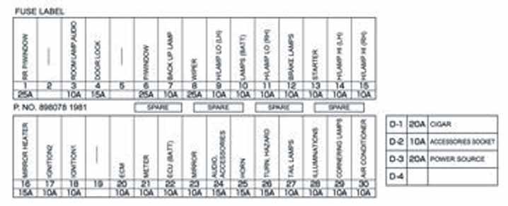
13 Fuse Location 14.13
14 Fuse Chart Fuse No. Capacity Indication on Label Main Parts (Load) F-1 25A RR P/WINDOW Rear Power Window Switch RH, Rear Power Window Switch LH Rear Power Window Relay F-2 F-3 10A ROOM LAMP, AUDIO Radio, Data Link Connector, Room Light F-4 15A DOOR LOCK Door Lock Relay F-5 F-6 25A P/WINDOW Front Power Window RH Switch, Front Power Window LH Switch Power Window Relay F-7 10A BACK UP LAMP Shift Lever Switch F-8 25A WIPER Wiper Main Relay, Wiper High Low Relay, Key On Relay, Front Wiper Motor, Front Washer Motor F-9 10A H/LAMP LO (LH) Headlight LH, Headlight Low Relay, DRL Control Unit F-10 10A LAMPS (BATT) DRL Relay, Headlight High Relay, Headlight Low Relay, Tail Relay F-11 10A H/LAMP LO (RH) Headlight RH, Headlight Low Relay, DRL Control Unit F-12 10A BRAKE LAMPS Stoplight Relay F-13 10A STARTER PIM.B, P/N Start Relay F-14 10A H/LAMP HI (LH) Headlight LH, Meter, Headlight High Relay F-15 10A H/LAMP HI (RH) Headlight RH, Headlight High Relay F-16 15A MIRROR HEATER Mirror Heater Switch, Blower Relay, Power Window Relay F-17 10A IGNITION2 Rear Window Lock Switch F-18 10A IGNITION1 Intermittent Relay, Vacuum Pump Relay F-19 F-20 10A ECM Stoplight Switch, PIM. B, Cruise Main Switch,TCM Relay F-21 10A METER Key On Relay, P/N Start Relay, Vacuum Pump Relay, Meter, Shift Lever Switch, Charge Relay, EHCU, Flasher Unit, DRL Relay F-22 10A ECU (BATT) Check Miles Switch, TCM Relay, Meter, Power train Control Module, PIM.B F-23 10A MIRROR F-24 15A AUDIO, ACCESSORIES Radio, Cigarette Lighter Relay, Power ACC Relay, PIM.A, PIM.B F-25 15A HORN Horn Relay
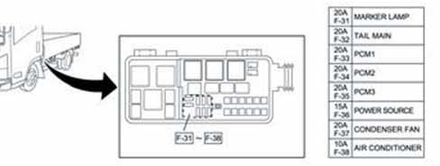
15 Fuse Chart (continued) Fuse No. Capacity Indication on Label Main Parts (Load) F-25 15A HORN Horn Relay F-26 15A TURN, HAZARD Flasher Unit F-27 10A TAIL LAMPS Tail Relay, Front Position Light RH, Front Position Light LH, ID1, ID2, ID3, Marker1, Marker2, Side Marker RH, Side Marker LH Tail Relay, Meter, Mirror Heater Switch, Blower Switch, Door Lock Switch, F-28 10A ILLUMINATIONS Cruise Main Switch, Rear Dome Light Switch, Hazard Switch, Check Miles Switch, Shift Lever Switch, Radio, Illumination Control Switch F-29 10A CORNERING LAMPS Tail Relay, DRL Relay F-30 10A AIR CONDITIONER DEF Switch, A/C Switch, AC Enable Relay, Magnetic Clutch Relay F-31 20A MARKER LAMP Marker Light Relay F-32 20A TAIL MAIN Tail Relay F-33 20A PCM1 PCM Main Relay, Power train Control Module Ignition Coil 1, Ignition Coil 3, Ignition Coil 5, Ignition Coil 7, Injector 1, Injector 3, Injector 5, Injector 7 F-34 20A PCM2 PCM Main Relay, Ignition Coil 2, Ignition Coil 4, Ignition Coil 6, Ignition Coil 8, Injector 2, Injector 4, Injector 6, Injector 8 F-35 20A PCM3 PCM Main Relay, Front Heater O2 Sensor LH, Front Heater O2 Sensor RH, Rear Heater O2 Sensor LH, Rear Heater O2 Sensor RH, Canister Purge Solenoid F-36 15A POWER SOURCE Rear Dome Light Relay, Front Manufacture Connector, Rear Manufacture Connector F-37 20A CONDENSER FAN Condenser Fan Relay F-38 10A AIR CONDITIONER Magnetic Clutch Relay F-39 (D-1) 20A CIGAR Cigarette Lighter Relay, Cigarette Lighter
16 Fuse Chart (continued) Fuse No. Capacity Indication on Label Main Parts (Load) F-40 (D-2) 10A ACCESSORIES SOCKET Power ACC Relay, ACC Socket F-41 (D-3) 20A POWER SOURCE Power Source Relay Chart Connector Relay Name Connector Relay Name No. No. X1 Stoplight X16 Taillight X2 Daytime Running Light B212 Accessory Power X3 Key On B215 Blower X4 TCM B218 Cigarette Lighter X5 P/N Start B246 Daytime Running Light X6 Wiper Main X17 Starter X7 Horn X20 Magnetic Clutch X8 Wiper High/ Low X21 Condenser Fan X9 - X22 Fuel Pump X10 Rear Power Window X23 Rear Dome Light X11 Charge X26 Marker Lamp X12 Front Power Window X28 PCM Main X13 Headlights (Low) X30 A/C Enable X14 Vacuum Pump X15 Headlight (High)

17 14.17 Relay Locations 1, 2 1. Fuse Panel in Cab 2. Relay Box on Frame
18 14.18 Slow Blow Fuses 1. Relay Box (on frame)
 14.")
19 Headlights (Low Beam) 14.19
")
20 Headlights (High Beam) 14.20

21 Tailights The connectors that match the end of frame tail and stop lamp harness can now be ordered through Isuzu & W-Series dealers. Chassis harness side part number Stop and tail lamp side part number

22 Roof Marker Lights 14.22

23 Roof Clearance Lights 14.23

24 Rear Turn Signal Lights The connectors that match the end of frame tail and stop lamp harness can now be ordered through Isuzu & W-Series dealers. Chassis harness side part number Stop and tail lamp side part number
 Pin Wire Color Circuit Color Function 1 BLK KX11")

25 J-111 Backup Alarm Connector End View Back up Light, Back up Alarm Circuit Connector Part Information WAY M (BLK) Pin Wire Color Circuit Color Function 1 BLK KX11 Ground 2 RED/BLU KA33 Back Up Alarm Supply Voltage Back Up Alarm Connector located on LH Rail of Last Crossmemeber. Chassis Side Connecotr Housings Terminal Seal TPA Matching Plug PED ASM
26 Cigar Lighter Circuits 14.26

27 Radio Circuits 14.27

28 Auxiliary Power Source Circuit Diagram 14.28
29 Fuel Tank Sending Unit Resistance Values Float Position Standard Resistance ( ) Empty Stop Full Stop 40
30 Model Year Fuel Tank Sending Unit Resistance Values Float Position Standard Resistance ( ) Empty Stop Full Stop 40
2012 Isuzu Truck 16.1
 16.1 NPR, NPR HD, NQR, NRR Diesel Electrical Symbols Symbol Meaning Symbol Meaning Symbol Meaning Fuse Electronic Parts Coil (Inductor), Solenoid Magnetic Valve Fusible Link Resistor Relay Fusible Link
2013 Isuzu Truck 16.1
 2013 Isuzu Truck 16.1 NPR HD, NQR, NRR Diesel Electrical Symbols Symbol Meaning Symbol Meaning Symbol Meaning Fuse Electronic Parts Coil (Inductor), Solenoid Magnetic Valve Fusible Link Resistor Relay
GENERAL INFORMATION PROCEDURE FOR HANDLING CHASSIS/DEALER CLAIMS GOVERNMENT REGULATIONS PAGE. General. Filing a Claim. Disposition of Damaged Parts
 GENERAL INFORMATION 1 PROCEDURE FOR HANDLING CHASSIS/DEALER CLAIMS General All chassis tendered for delivery by the Transportation Company are to be accepted by the Body Company. If a chassis has been
POWER SOURCE (Current Flow Chart)
") POWER SOURCE (Current Flow Chart) The chart below shows the route by which current flows from the battery to each electrical source (Fusible Link, Circuit Breaker, Fuse, etc.) and other parts. The next
POWER SOURCE (Current Flow Chart) The chart below shows the route by which current flows from the battery to each electrical source (Fusible Link, Circuit Breaker, Fuse, etc.) and other parts. The next
POWER SOURCE (Current Flow Chart)
") The chart below shows the route by which current flows from the battery to each electrical source (Fusible Link, Circuit Breaker, Fuse, etc.) and other parts. The next page and following pages show the
The chart below shows the route by which current flows from the battery to each electrical source (Fusible Link, Circuit Breaker, Fuse, etc.) and other parts. The next page and following pages show the
CIRCUIT DIAGRAMS GROUP CONTENTS HOW TO READ CIRCUIT DIAGRAMS BACKUP LIGHT TURN SIGNAL LIGHT AND HAZARD WARNING LIGHT...
 90-1 GROUP 90 CIRCUIT DIAGRAMS CONTENTS HOW TO READ CIRCUIT DIAGRAMS................................. 90-4 JUNCTION BLOCK.............. 90-10............. 90-12 CENTRALIZED JUNCTION........ 90-18 POWER
G ELECTRICAL WIRING ROUTING
 G ELECTRICAL WIRING ROUTING Position of Parts in Engine Compartment A 1 A/C Condenser Fan Motor A 2 A/C Magnetic Clutch and Lock Sensor A 3 A/C Triple Pressure SW (A/C Dual and Signal Pressure SW) A 4
CONFIGURATION DIAGRAMS
 80A-1 GROUP 80A CONFIGURATION DIAGRAMS CONTENTS OVERALL CONFIGURATION DIAGRAM...................... 80A-2 HOW TO READ CONFIGURATION DIAGRAMS.................... 80A-3 ENGINE COMPARTMENT......... 80A-4
G ELECTRICAL WIRING ROUTING
 G ELECTRICAL WIRING ROUTING Position of Parts in Engine Compartment A 1 A/C Condenser Fan Motor A 2 A/C Magnetic Clutch and Lock Sensor A 3 A/C Triple Pressure SW (A/C Dual and Single Pressure SW) A 4
Position of Parts in Engine Compartment
 ELECTRICAL WIRING ROUTING [5S FE] Position of Parts in Engine Compartment A 1 A/C Condenser Fan Motor E 4 Engine Coolant Temp. Sensor (EFI Water Temp. A 2 A/C Magnetic Clutch and Lock Sensor Sensor) A
CONFIGURATION DIAGRAMS
 80A-1 GROUP 80A CONFIGURATION DIAGRAMS CONTENTS OVERALL CONFIGURATION DIAGRAM...................... 80A-2 HOW TO READ CONFIGURATION DIAGRAMS.................... 80A-3 ENGINE COMPARTMENT......... 80A-4
G ELECTRICAL WIRING ROUTING [1MZ-FE] Position of Parts in Engine Compartment
![G ELECTRICAL WIRING ROUTING [1MZ-FE] Position of Parts in Engine Compartment](/thumbs/87/97394184.jpg "G ELECTRICAL WIRING ROUTING [1MZ-FE] Position of Parts in Engine Compartment") G ELECTRICAL WIRING ROUTING [1MZ-FE] Position of Parts in Engine Compartment A 1 A/C Ambient Temp. Sensor A 2 A/C Condenser Fan Motor A 3 A/C Magnetic Clutch and Lock Sensor A 4 A/C Triple Pressure SW
G ELECTRICAL WIRING ROUTING [1MZ-FE] Position of Parts in Engine Compartment A 1 A/C Ambient Temp. Sensor A 2 A/C Condenser Fan Motor A 3 A/C Magnetic Clutch and Lock Sensor A 4 A/C Triple Pressure SW
CONFIGURATION DIAGRAMS
 80-1 GROUP 80 CONFIGURATION DIAGRAMS CONTENTS CONFIGURATION DIAGRAMS......................... 80A SPLICE LOCATIONS................................. 80B 80A-2 GROUP 80A CONFIGURATION DIAGRAMS CONTENTS OVERALL
CIRCUIT DIAGRAMS GROUP CONTENTS HOW TO READ CIRCUIT DIAGRAMS VANITY MIRROR LIGHT JUNCTION BLOCK...
 90-1 GROUP 90 CONTENTS HOW TO READ................................. 90-4 JUNCTION BLOCK.............. 90-10 JOINT CONNECTOR............. 90-12 CENTRALIZED JUNCTION........ 90-13 POWER DISTRIBUTION SYSTEM..
G ELECTRICAL WIRING ROUTING
 2 6 G ELECTRICAL WIRING ROUTING [2JZ-GTE] Position of Parts in Engine Compartment A 1 A/C Ambient Temp Sensor A 2 A/C Condensor Fan Motor A 3 A/C Triple Pressure SW (A/C Dual and Single Pressure SW) A
G ELECTRICAL WIRING ROUTING [5VZ FE] TOYOTA TACOMA (EWD517U) Position of Parts in Engine Compartment
![G ELECTRICAL WIRING ROUTING [5VZ FE] TOYOTA TACOMA (EWD517U) Position of Parts in Engine Compartment](/thumbs/82/86578697.jpg "G ELECTRICAL WIRING ROUTING [5VZ FE] TOYOTA TACOMA (EWD517U) Position of Parts in Engine Compartment") G ELECTRICAL WIRING ROUTING [5VZ FE] Position of Parts in Engine Compartment A 5 A/C Magnetic Clutch A 7 A/T Oil Temp. Sensor A22 ABS Actuator with ECU A23 Air Fuel Ratio Sensor (Bank 1 Sensor 1) A24 ADD
G ELECTRICAL WIRING ROUTING [5VZ FE] Position of Parts in Engine Compartment A 5 A/C Magnetic Clutch A 7 A/T Oil Temp. Sensor A22 ABS Actuator with ECU A23 Air Fuel Ratio Sensor (Bank 1 Sensor 1) A24 ADD
G ELECTRICAL WIRING ROUTING [2ZZ GE] Position of Parts in Engine Compartment
![G ELECTRICAL WIRING ROUTING [2ZZ GE] Position of Parts in Engine Compartment](/thumbs/82/84806793.jpg "G ELECTRICAL WIRING ROUTING [2ZZ GE] Position of Parts in Engine Compartment") G ELECTRICAL WIRING ROUTING [2ZZ GE] Position of Parts in Engine Compartment A 1 A/C Magnetic Clutch A 2 ABS Speed Sensor Front LH A 3 ABS Speed Sensor Front RH A 4 Airbag Sensor Front LH A 5 Airbag Sensor
G ELECTRICAL WIRING ROUTING [2ZZ GE] Position of Parts in Engine Compartment A 1 A/C Magnetic Clutch A 2 ABS Speed Sensor Front LH A 3 ABS Speed Sensor Front RH A 4 Airbag Sensor Front LH A 5 Airbag Sensor
Position of Parts in Engine Compartment
 ELECTRICAL WIRING ROUTING [5S FE] Position of Parts in Engine Compartment A 1 A/C Ambient Temp. Sensor D 1 Distributor A 2 A/C Condenser Fan Motor A 3 A/C Idle Up VSV E 1 ECT Solenoid A 4 A/C Magnet Clutch
Position of Parts in Engine Compartment
 ELECTRICAL WIRING ROUTING [3S GTE] Position of Parts in Engine Compartment A 1 A/C Ambient Temp. Sensor D 1 Date Link Connector 1 (Check Connector) A 2 A/C Condenser Fan Motor D 2 Distributor A 4 A/C Magnetic
Position of Parts in Engine Compartment
 [1UZ FE] Position of Parts in Engine Compartment A 1 A/C Ambient Temp. Sensor E 4 Engine Coolant Temp. Sensor (Water Temp. Sensor A 2 A/C Dual Pressure SW and A/C High Pressure SW (for Cooling Fan)) A
G ELECTRICAL WIRING ROUTING
 G ELECTRICAL WIRING ROUTING Position of Parts in Engine Compartment A 1 A/C Ambient Temp. Sensor A 2 A/C Condenser Fan Motor A 3 A/C Magnetic Clutch and Lock Sensor A 4 A/C Triple Pressure SW (A/C Dual
WIRING DIAGRAM 1. General Description
 Page 1. General Description...1 2. Wiring Diagram...10 (1) POWER SUPPLY ROUTING...10 (2) ENGINE CONTROL SYSTEM (SOHC)...14 (3) ENGINE CONTROL SYSTEM (2.0 DOHC NA)...18 (4) ENGINE CONTROL SYSTEM (2.5 )...22
G ELECTRICAL WIRING ROUTING
 2 6 G ELECTRICAL WIRING ROUTING Position of Parts in Engine Compartment A1 A/C Front Magnetic Valve A3 A/C Magnetic Clutch A6 A/T Flud Temp. Sensor A7 ABS Actuator A8 ABS Actuator A10 ABS Speed Sensor
SECTION 9A BODY WIRING SYSTEM
 SECTION 9A BODY WIRING SYSTEM Caution: Disconnect the negative battery cable before removing or installing any electrical unit or when a tool or equipment could easily come in contact with exposed electrical
L PART NUMBER OF CONNECTORS
 L PART NUMBER OF CONNECTORS Code Part Name Part Number Code Part Name Part Number A 1 A/C Ambient Temp. Sensor 90980-11070 B15 Blower Motor Controller (Rear) 90980-11136 A 2 A/C Magnetic Clutch 90980-11271
UNIVERSAL WIRING HARNESS Installation Manual
 UNIVERSAL WIRING HARNESS Installation Manual Terminals are provided for most connections on your wiring kit. Following the gauge manufacturer s instructions, use the terminals supplied with your gauge
Layout Diagrams. Section CONTENTS. General Layout Diagram Floor / Roof Engine Compartment Door
 1-1 Section 1 Layout Diagrams CONTENTS General Layout Diagram...1-3 Engine Compartment...1-4 Engine / Transmission...1-6 Floor / Roof...1-16 Door...1-18 Boot Compartment...1-20 Instrument Panel...1-10
BUZZERS, RELAYS & TIMERS CIRCUIT PROTECTION DEVICES CONTROL UNITS 2002 TOYOTA RAV4 BUZZERS, RELAYS & TIMERS LOCATION
 2002 TOYOTA RAV4 BUZZERS, RELAYS & TIMERS BUZZERS, RELAYS & TIMERS LOCATION A/F Relay C/OPN Relay DEF Relay EFI Main Relay Fan No. 1 Relay Fan No. 2 Relay Fan No. 3 Relay FR FOG Relay H-LP Relay In engine
INSTRUCTIONS. 20 Circuit Wiring Kit Instructions October 2009, Speedway Motors, Inc.
 1 MAIN FUSE PANEL The main fuse panel harness s designed to be mounted under the dash a the firewall in an area close to the steering column. The enclosed representation of the main dash harness shows
BUZZERS, RELAYS & TIMERS
 ELECTRICAL COMPONENT LOCATOR 1994 ELECTRICAL COMPONENT LOCATION Mazda Electrical s BUZZERS, RELAYS & TIMERS BUZZERS, RELAYS & TIMERS LOCATION ABS s Motor Relay On top of ABS pump, on right rear corner
Fuse/Relay Information
 /Relay Information Under-dash /Relay Box C901 (To turn signal/hazard relay) C902 (To blower motor relay) C903 (To rear window defogger relay) C405 C404 C904 (To integrated control unit) C602 (To dashboard
2000 Volkswagen Jetta GL
 Fig. 8: Locating Battery Fuse Panel Fuses Courtesy of VOLKSWAGEN UNITED STATES, INC. FUSE IDENTIFICATION (BATTERY FUSE PANEL) Fuse No. Amp Circuits Protected Rating 162 Engine Codes 50 Secondary Air Injector
jegs.com
 Contents Wiring Harness w/ Fuse Panel Installation Instructions Turn Signal Plug w/ Terminals 2 Headlight Plugs 3/4 Grommet 10 ¼ Terminals 4 Ring Terminals 10 Wire Ties Fusible Link 2 Screws & Nuts 2 Plastic
C915 - A147 Powertrain control module (PCM) C916 - A7 ABS control module
 C916 - A7 ABS control module") C915 - A147 Powertrain control module (PCM) C916 - A7 ABS control module C1152 - K11 Intermittent wiper relay, front C1153 - K1 Rear window heater relay C1154 - K18 ABS main relay C1155 - K25 ABS Pump
C915 - A147 Powertrain control module (PCM) C916 - A7 ABS control module C1152 - K11 Intermittent wiper relay, front C1153 - K1 Rear window heater relay C1154 - K18 ABS main relay C1155 - K25 ABS Pump
HOW TO USE SYSTEM WIRING DIAGRAMS
 HOW TO USE SYSTEM WIRING DIAGRAMS 1998 Pontiac Bonneville GENERAL INFORMATION Using Wiring Diagrams All Models INTRODUCTION This CD obtains wiring diagrams and technical service bulletins, containing wiring
GENERAL INFORMATION Using Wiring Diagrams. All Models
 Article Text ARTICLE BEGINNING GENERAL INFORMATION Using Wiring Diagrams All Models INTRODUCTION Mitchell obtains wiring diagrams and technical service bulletins, containing wiring diagram changes from
Symptom Suspected Area See page Ignition switch is not set to each position. 11.Ignition switch BE 14
 BE2 BODY ELECTRICAL PROBLEM SYMPTOMS TABLE IGNITION SWITCH AND KEY UNLOCK WARNING SWITCH BE0ON18 Ignition switch is not set to each position. 11.Ignition switch BE14 Key unlock warning system does not
CONFIGURATION DIAGRAMS
 GROUP 80 CONFIGURATION DIAGRAMS CONTENTS OVERALL CONFIGURATION DIAGRAM...................... 80-2......... 80-3 .. 80-3 .. 80-5 ...... 80-7 INSTRUMENT PANEL............ 80-9 FLOOR
BUZZERS, RELAYS & TIMERS
 BUZZERS, RELAYS & TIMERS 1997 MAZDA MX-5 Miata BUZZERS, RELAYS & TIMERS Location A/C Relay In right front of engine compartment, near radiator. See Fig. 1. Condenser Fan Relay In right front of engine
3/25 Switch, power sunroof 3/26 Control module, driver's seat 3/27 Control module, passenger's seat 3/28 Switch for heated driver's seat 3/29 Switch
 List of Components 1/1 Battery 2/1 Headlight relay with bulb failure sensor 2/2 Foglight relay 2/3 Regulator DIM-DIP 2/4 Intermittent wiper relay, windshield wipers 2/5 Relay, seat belt reminder/ignition
ELECTRICAL COMPONENT LOCATOR
 ELECTRICAL COMPONENT LOCATOR 1988 Toyota Celica 1988 TOYOTA Celica Electrical Components ---------------------------------------------------------------------- BUZZERS, RELAYS & TIMERS ----------------------------------------------------------------------
 http://www.prodemand.com/print/index?content=tabs&module=true&tab=true&terms=tr... Page of //0 00 Chevrolet Silverado.L Eng 00 Service Manual: WIRING DIAGRAMS - 00 Print Date: //0 ENGINE PERFORMANCE Tip:
SOUL GDI REPAIR AND MAINTENANCE
 SOUL 2013-1.6 GDI REPAIR AND MAINTENANCE (First Numbers are page number within section - Numbers in parenthesis are overall document page) GENERAL INFORMATION (23 PAGES) 01-07 (01-07): Identification Number
3/22 Switch for rear power window lifts 3/23 Switch for power door mirror, driver's side 3/24 Switch for power door mirror, passenger's side 3/25
 List of Components 1/1 Battery 2/2 Relay, front foglights USA/CDN 2/3 Regulator DIM-DIP 2/4 Intermittent relay, windshield wipers 2/5 Relay, seat belt reminder/ignition key warning 2/6 Bypass relay 151
FUSE DETAILS. Fuse Details
 2003 Jaguar S-Type (X200) V8-4.2L Vehicle > Power and Ground Distribution > Fuse > Application and ID > Components FUSE DETAILS Fuse Details https://my.alldata.com/repair/#/repair/article/40444/component/1169/itype/389/nonstandard/1247914
Diesel Technology: Electrical and Electronic Systems
 Diesel Technology: Electrical and Electronic Systems NATEF Crosswalk The following NATEF Electrical/Electronic Systems tasks (rev. 2001) are covered in this publication. The chart shows where each task
Fuse and Relay Information
 11 1 Fuse and Relay Information Central Junction Box (CJB) (14A067) PCM power Trailer tow, battery charge Starter (11450) Blower motor Rear window defrost F2.602 C270p F2.101 F2.107 F2.102 F2.108 F2.601
2005 Buick Rendezvous 3.6L Eng VIN 7 Ultra Service Manual: FUSES & CIRCUIT BREAKERS Print Date: 9/16/2018
 Page 1 of 6 2005 Buick Rendezvous 3.6L Eng VIN 7 Ultra Service Manual: FUSES & CIRCUIT BREAKERS Print Date: IDENTIFICATION CAUTION: When battery is disconnected, vehicle computer and memory systems may
Telephone: Fax: VAT Registration No.:
 Telephone: Fax: VAT Registration No.: K143 AC compressor clutch relay X88 AC connector S63 AC refrigerant pressure switch S341 AC refrigerant triple pressure switch A16 Anti-lock braking system (ABS) control
Passat Fitting Locations No. 208 / 1 Edition
 Sivu 1/11 Passat Fitting Locations No. 208 / 1 Edition 02.2007 Relay and fuse assignment From May 2002 Relay locations on 13 position additional relay carrier above relay plate 1 - Radiator fan relay -
1994 Cadillac Seville STS
 Fig. 2: High-Current Fuse Panel ID (1994-95 Seville) L/H Maxi-Fuse & Circuit Breaker Identification 1-50 Amp STRG 1-2 Retained Accessory Power (Radio/Wipers), Starter, Trunk Comp Fuses 8 & 9 2-60 Amp BODY
Volkswagen Cabriolet DIY Guide Relay/Fuse Diagrams & Electrical System
 Volkswagen Cabriolet DIY Guide Relay/Fuse Diagrams & Electrical System Notes: 1980-1982 cars use ceramic fuses! 1980-1982 cars had a recall for the fuel pump relay. These cars should have a relay bypass
Instrument Cluster 30 33B 39B A B C D E F E F G H J. Connector. Circuit Branch #4. Circuit Branch #5. Circuit. Branch #6 150A. Ground.
 16 4D, 43 4B 4A & 130 100 50 39A,B,C 300 4C 4B 4C 107 3C 3D 3C 3G 3B 3F 3A 16A 3G 116 104 93 3B 3D 2E 16A 2C 2D 2B 2A 44 40 27A 40B 115 27 40A,C,E 8A,B,C Mating is plugged into accessory connector Power
Underhood fuse block is located at the left side of the engine compartment to the rear of the battery. See Fig. 7.
 Page 1 of 5 UNDERHOOD FUSE BLOCK NOTE: Underhood fuse block is located at the left side of the engine compartment to the rear of the battery. See Fig. 7. Fig. 7: Locating Underhood Fuse Block Courtesy
Updated 19th May 2010
 Lotus Service Notes Section MP.14e ELECTRICS SECTION MP.14e CIRCUIT DIAGRAMS 2011MY ELISE WITH 1ZR POWERTRAIN Contents List Circuit Diagrams - 2 Circuit Diagrams - 3-47 Fuse Layout - 48 Colour Codes &
G - TESTS W/CODES - 2.2L
 G - TESTS W/CODES - 2.2L 1994 Toyota Celica 1994 ENGINE PERFORMANCE Toyota 2.2L Self-Diagnostics Celica INTRODUCTION If no faults were found while performing F - BASIC TESTING, proceed with self-diagnostics.
TOYOTA HILUX FACTORY SERVICE, REPAIR, SHOP MANUAL - HILUX VIGO - YEARS MANUAL -!
 Instant Manual Download TOYOTA HILUX 2005 2006 2007 2008 2009 FACTORY SERVICE, REPAIR, SHOP MANUAL - HILUX VIGO - YEARS 05 06 07 08 09 - MANUAL -! Download Here TOYOTA HILUX 2005-2009 (2005 2006 2007 2008
Buckle SW Rear RH C 1 Camshaft Position Sensor Camshaft Timing Oil Control Valve RH. Crankshaft Position Sensor
 A 1 A/C Ambient Temp. Sensor 90980 11070 A 2 A/C Magnetic Clutch and ock Sensor 90980 11016 A 3 A/C Pressure Sensor 90980 10845 A 4 A/C Solenoid 90980 10901 A 5 ABS & TRAC & VSC Actuator 90980 11451 A
Fuse and Relay Information
 11-1 Fuse and Relay Information Battery Junction Box (BJB) (14A003) PCM power diode Air suspension compressor Front fog lamp cutoff Police power Traction control indicator A/C clutch Fuel pump C1300 C1008
CONNECTOR/GROUND/SPLICE LOCATION
 AN 8W-91 CONNECTOR/GROUND/SPLICE LOCATION 8W-91-1 8W-91 CONNECTOR/GROUND/SPLICE LOCATION TABLE OF CONTENTS page CONNECTOR/GROUND/SPLICE LOCATION DESCRIPTION...1 CONNECTOR/GROUND/SPLICE LOCATION DESCRIPTION
Powertrain Management: Electrical Diagrams Fuel Injection System
 1995 Volvo 940 L4-2.3L SOHC VIN 88 B230F Copyright 2009, ALLDATA 9.70 Page 1 Powertrain Management: Electrical Diagrams Fuel Injection System Wiring Diagram 1995 Volvo 940 L4-2.3L SOHC VIN 88 B230F Copyright
IDENTIFICATION COMPONENT LOCATION MENU
 WIRING DIAGRAMS 1993 Mitsubishi Diamante 1993 WIRING DIAGRAMS Mitsubishi Wiring Diagrams Mitsubishi; Diamante IDENTIFICATION COMPONENT LOCATION MENU COMPONENT LOCATIONS TABLE Component Figure No. (Location)
5/16/2017 ALLDATA Repair - Vehicle Information Volvo V L5-2.4L VIN 61 B5244S
 1/1 Battery 2/16 Relay, Intermittent Rear Window Wiping On/Off 2/17 Horn Relay 2/22 AC Relay 2/23 Fuel Pump Relay 2/29 Relay, Extended D1 Feed 2/30 X Feed Overload Relay 2/31 15-Feed Overload Relay 2/32
1991 TOYOTA Electrical Components MR2. evaporator. compartment. ARTICLE BEGINNING BUZZERS, RELAYS & TIMERS
 ELECTRICAL COMPONENT LOCATOR Article Text ARTICLE BEGINNING 1991 TOYOTA Electrical Components MR2 BUZZERS, RELAYS & TIMERS A/C Compressor Clutch Relay Under right side of dash, on evaporator. Circuit Opening
Updated 12th September 2011
 Lotus Service Notes Section MP.14g ELECTRICS SECTION MP.14g CIRCUIT DIAGRAMS 2011MY ELISE 1ZR POWERTRAIN WITH BOSCH ABS VIN BH_10931 ONWARDS Contents List Circuit Diagrams - 2 Circuit Diagrams - 3-49 Fuse
 http://www.prodemand.com/print/index?content=tabs&module=true&tab=true&terms=t... Page of // 0 Chevrolet Traverse.L Eng LT Service Manual: WIRING DIAGRAMS Print Date: // ENGINE PERFORMANCE >.L VIN D Fig
Diagnostic Trouble Code (DTC) List - Vehicle
 List - Vehicle") Document ID# 850406 2002 Pontiac Firebird Diagnostic Trouble Code (DTC) List - Vehicle DTC DTC 021 and/or 031 DTC 022 and/or 032 DTC 023 or 033 DTC 24/34 DTC 025 and/or 035 DTC 041 DTC 042 DTC 043 DTC
Document ID# 850406 2002 Pontiac Firebird Diagnostic Trouble Code (DTC) List - Vehicle DTC DTC 021 and/or 031 DTC 022 and/or 032 DTC 023 or 033 DTC 24/34 DTC 025 and/or 035 DTC 041 DTC 042 DTC 043 DTC
Lotus Service Notes Section MP.14h
 Lotus Service Notes Section MP.14h ELECTRICS SECTION MP.14h CIRCUIT DIAGRAMS 2012MY ELISE 1ZR & 2ZR POWERTRAIN FROM VIN CH_10205 ONWARDS Description Page Contents List Circuit Diagrams 2 Circuit Diagrams
5. Engine Control Module (ECM) I/O Signal
 I/O Signal") 5. A: ELECTRICAL SPECIFICATION B134 B135 B136 B137 17 16 15 14 13 12 11 10 9 8 27 26 25 24 23 22 21 20 19 18 34 33 32 31 30 29 28 19 18 17 16 15 14 13 12 11 10 9 8 27 26 25 24 23 22 21 20 35 34 33 32 31
5. A: ELECTRICAL SPECIFICATION B134 B135 B136 B137 17 16 15 14 13 12 11 10 9 8 27 26 25 24 23 22 21 20 19 18 34 33 32 31 30 29 28 19 18 17 16 15 14 13 12 11 10 9 8 27 26 25 24 23 22 21 20 35 34 33 32 31
ON-BOARD DIAGNOSTICS II SYSTEM. 5. Specified Data. Signal (V) Ignition SW ON (Engine OFF)
 Ignition SW ON (Engine OFF)") 1. ENGINE CONTROL MODULE (ECM) I/O SIGNAL OBD0092A Crankshaft Camshaft Mass air flow Throttle Signal (+) 8 0 7 +7 Sensor output waveform Signal ( ) 29 0 0 Shield 54 0 0 Signal (+) 7 0 7 +7 Sensor output
1. ENGINE CONTROL MODULE (ECM) I/O SIGNAL OBD0092A Crankshaft Camshaft Mass air flow Throttle Signal (+) 8 0 7 +7 Sensor output waveform Signal ( ) 29 0 0 Shield 54 0 0 Signal (+) 7 0 7 +7 Sensor output
Powertrain DTC Summaries EOBD
 Powertrain DTC Summaries Quick Reference Diagnostic Guide Jaguar S-TYPE V6, V8 N/A and V8 SC 2002.5 Model Year Refer to pages 2 9 for important information regarding the use of Powertrain DTC Summaries.
Telephone: Fax: VAT Registration No.:
 Telephone: Fax: VAT Registration No.: Terminal side Wire side Component/circuit description ECM pin Signal Condition Typical value Oscilloscope setting (Suggested settings - Voltage/time per division)
Symptom Suspect Area See page. 11.Ignition Switch 12.Power Source Circuit. Symptom Suspect Area See page
 BE2 PROBLEM SYMPTOMS TABLE IGNITION SWITCH: BE18204 Ignition switch is not set to each position. KEY UNLOCK WARNING SWITCH: 11.Ignition Switch 12.Power Source Circuit BE15 Key unlock warning system does
Powertrain DTC Summaries EOBD
 Powertrain DTC Summaries Quick Reference Diagnostic Guide Jaguar X-TYPE 2.0 L 2002.25 Model Year Refer to page 2 for important information regarding the use of Powertrain DTC Summaries. Jaguar X-TYPE 2.0
ECU Pinout Chart 2002 WRX Engine Control Module (ECM) I/O Signals. Wire Ignition SW Color ON Engine ON (Idling)
 I/O Signals. Wire Ignition SW Color ON Engine ON (Idling)") ECU Connector Diagram ECU Pinout Chart 2002 WRX Engine Control Module (ECM) I/O Signals Signal (V) Content Pin Wire Ignition SW Color ON Engine ON (Idling) Note (Engine OFF) Crankshaft Signal (+) B2 W
ECU Connector Diagram ECU Pinout Chart 2002 WRX Engine Control Module (ECM) I/O Signals Signal (V) Content Pin Wire Ignition SW Color ON Engine ON (Idling) Note (Engine OFF) Crankshaft Signal (+) B2 W
ELECTRICAL CENTER IDENTIFICATION VIEWS > BODY CONTROL MODULE (BCM) LABEL
 LABEL") 2008 Chevrolet Cobalt 2.2L Eng LS WIRING SYSTEMS AND POWER MANAGEMENT - COMPONENT VIEWS & COMPONENT CONNECTOR END VIEWS ELECTRICAL CENTER IDENTIFICATION VIEWS > BODY CONTROL MODULE (BCM) LABEL Fig 1: View
2008 Chevrolet Cobalt 2.2L Eng LS WIRING SYSTEMS AND POWER MANAGEMENT - COMPONENT VIEWS & COMPONENT CONNECTOR END VIEWS ELECTRICAL CENTER IDENTIFICATION VIEWS > BODY CONTROL MODULE (BCM) LABEL Fig 1: View
IDENTIFICATION IDENTIFICATION > ENGINE COMPARTMENT FUSE/RELAY CENTER Chevrolet Colorado 3.5L Eng. Vehicle Reference: FUSES & CIRCUIT BREAKERS
 1 of 6 2/1/2015 5:42 PM Vehicle Reference: FUSES & CIRCUIT BREAKERS IDENTIFICATION 2005 Chevrolet Colorado 3.5L Eng CAUTION: When battery is disconnected, vehicle computer and memory systems may lose memory
INSTRUCTIONS Circuit Wiring Kit Instructions _2017. Fuse Box Connections. (viewed from underside) 2018, Speedway Motors, Inc.
 2018, Speedway Motors, Inc.") Fuse Box Connections (viewed from underside) 4D 4C 100 50 300 4D 4C 4B 4A 43 107 39 103 3B 2G 104 93 2F 2E 2D 2C 2B 40 69A 102 101 105 2G 2F 2E 3A A 2A B 40A,B 27 69A 106 201, Speedway Motors, Inc. 1 Fuse
Fuse Box Connections (viewed from underside) 4D 4C 100 50 300 4D 4C 4B 4A 43 107 39 103 3B 2G 104 93 2F 2E 2D 2C 2B 40 69A 102 101 105 2G 2F 2E 3A A 2A B 40A,B 27 69A 106 201, Speedway Motors, Inc. 1 Fuse
5. Engine Control Module (ECM) I/O Signal
 I/O Signal") 5. Engine Control Module (ECM) I/O Signal A: ELECTRICAL SPECIFICATION B134 B135 B136 B137 17 16 15 14 13 12 11 10 9 8 27 26 25 24 23 22 21 20 19 18 34 33 32 31 30 29 28 19 18 17 16 15 14 13 12 11 10 9
5. Engine Control Module (ECM) I/O Signal A: ELECTRICAL SPECIFICATION B134 B135 B136 B137 17 16 15 14 13 12 11 10 9 8 27 26 25 24 23 22 21 20 19 18 34 33 32 31 30 29 28 19 18 17 16 15 14 13 12 11 10 9
Fuses FUSE BOX LOCATIONS. Engine compartment fuse box
 FUSE BOX LOCATIONS Engine compartment fuse box 1 2 LAN2333 Remove the plastic cover by pressing the tabs. The fuse values and locations and the circuits protected are shown on the plastic cover. LAN2332
 Page of 0 Chevrolet Aveo.L Eng LS Service Manual: WIRING DIAGRAMS Print Date: HEADLIGHTS Fig : Headlights Circuit LOW HIGH FRT FOG EF FRT FOG HOT W/ IGN ALL ENERGIZED TIMES DASH, IN DOOR OPENING) LO LH
J POWER SOURCE (Current Flow Chart)
") J POWER SOURCE (Current Flow Chart) 374 J 375 J POWER SOURCE (Current Flow Chart) Driver Side J/B (See Page 26) 7.5A ECU ACC Automatic Air Conditioning (Front) Automatic Light Control Back Door Opener
J POWER SOURCE (Current Flow Chart) 374 J 375 J POWER SOURCE (Current Flow Chart) Driver Side J/B (See Page 26) 7.5A ECU ACC Automatic Air Conditioning (Front) Automatic Light Control Back Door Opener
TOYOTA STARLET EP82. Wiring connections, Connector IDs & Loom Layouts. Rev 1.2 Last Updated October 2011
 TOYOTA STARLET EP8 Wiring connections, Connector IDs & Loom Layouts Rev. Last Updated October 0 Author & Copyright : Alan Mears Location : Perth, Western Australia Contact Email : alan@mearcat.com.au Online
Service Bulletin. Applies To: MDX ALL 2006 MDX From VIN 2HNYD18..6H thru 2HNYD18..6H535538
 Service Bulletin Applies To: 2003 05 MDX ALL 2006 MDX From VIN 2HNYD18..6H500001 thru 2HNYD18..6H535538 06-028 July 13, 2007 MIL Comes On With DTC P0335, P0339, P0385, or P0389, and the Engine Runs Roughly
40A A 40B. Horn Relay Connector. Brake Switch. Third Brake Light. Brake Switch. Brake Switch. Wires. page 3. Rear Body Feed Wires.
 Fuse Box Connections (viewed from underside) 4D 4C 4D 0 50 300 4C 43 7 39 3 6 4 93 A 2G 2F 2E 2D 2C 2B 2G 2F 2E 40 69A 2 1 5 27 69A 3A B 40A,B 11A,B 40A 156 Dimmer Dome Feed page 2 Horn Relay 2D 2 29 40B
1993 FD3S Touring Trim Electrical FSM Index/Supplement
 1993 FD3S Touring Trim Electrical FSM Index/Supplement Purpose: This is simply a searchable index of connectors that are found in the various 1993 FD3S wiring harnesses. Each entry shows the purpose of
12-2. Specifications. & Dimensions. These specifications are subject to change without notice. Specifications/Specifications.
 Specifications Specifications... 12-2 Dimensions... 12-2 Engine... 12-3 Fuel... 12-3 Engine oil... 12-4 Manual transmission, front differential and rear differential gear oil... 12-6 Fluids... 12-7 Engine
Telephone: Fax: VAT Registration No.:
 Telephone: Fax: VAT Registration No.: Name: Manufacturer: Ford Address: Model: Year: 1994 Registration: Tel - Private: Tel - Business: Mileage: Job number: Terminal side Wire side Component/circuit description
C6 Corvette DIC Codes
 C6 Corvette DIC Codes B0159 Outside Air Temp Sensor B2910 Steering Column Lock Password Incorrect B0164 Pass Compartment Temp Sensor B2981 Right Front Door Handle Switch B0174 Output Air Temp Sensor 1
Infinitybox, LLC Addendum to Factory Five 818 Configuration Sheet Installation Guide Table of Contents
 Infinitybox, LLC Addendum to Factory Five 818 Configuration Sheet Installation Guide Table of Contents Overview... 2 Wiring Ignition Input to MASTERCELL... 3 Wiring Ignition Outputs to POWERCELLs... 4
2002 ENGINE PERFORMANCE. Self-Diagnostics - RAV4. Before performing testing procedures, check for any related Technical Service Bulletins (TSBs).
.") 2002 ENGINE PERFORMANCE Self-Diagnostics - RAV4 INTRODUCTION NOTE: Before performing testing procedures, check for any related Technical Service Bulletins (TSBs). To properly diagnosis and repair this
2002 ENGINE PERFORMANCE Self-Diagnostics - RAV4 INTRODUCTION NOTE: Before performing testing procedures, check for any related Technical Service Bulletins (TSBs). To properly diagnosis and repair this
FUSES & CIRCUIT BREAKERS
 FUSES & CIRCUIT BREAKERS FUSES & CIRCUIT BREAKERS 1989-95 FUSES & CIRCUIT BREAKERS Ford Motor Co. INTERIOR FUSE PANEL IDENTIFICATION (1983-88 MODELS) On all models, the fuse panel is located under the
2001 Lincoln LS V6-3.0L DOHC VIN S Vehicle > Powertrain Management > Diagrams > Electrical - Interactive Color (Non OE) Engine Controls - Page 1 of 4
 Engine Controls - Page 1 of 4") /0/0 Engine Controls (Powertrain Management) - ALLDATA 00 Lincoln LS V-.0L DOHC VIN S Vehicle > Powertrain Management > Diagrams > Electrical - Interactive Color (Non OE) Engine Controls - Page of https://my.alldata.com/repair/#/repair/article//component//itype//nonstandard/0
/0/0 Engine Controls (Powertrain Management) - ALLDATA 00 Lincoln LS V-.0L DOHC VIN S Vehicle > Powertrain Management > Diagrams > Electrical - Interactive Color (Non OE) Engine Controls - Page of https://my.alldata.com/repair/#/repair/article//component//itype//nonstandard/0
Rear Body 40D 156A 24 17A 151 3D. 8A,8B,8C under hood light. Horn Relay 91
 fuse box as viewed from the wire entry side Mating connector is plugged into Power Accessory connector 40D Rear Body 19 18 9B 30 LH Courtesy Light 40A,D 4D, 43 156B,C 16 16A 4C 3D 3C 16A 3G 4B 3G 116 4A&130
Part 8 SPECIFICATIONS
 Part 8 SPECIFICATIONS Dimensions and weight Engine Fuel Service specifications Tires Fuses Dimensions and weight P195/70R 14 tire Overall length 4783 (188.3) Overall width 1780 (70.1) Overall height 1416
COMPONENT LOCATIONS GROUP 70 CONTENTS INSPECTION CONNECTOR AND SPARE CONNECTOR SENSOR DIODE SOLENOID VALVE...
 GROUP 70 COMPONENT LOCTIONS CONTENTS SENSOR....................... 70-2 DIODE........................ 70-8 ECU.......................... 70-9 FUSIBLE LINK ND FUSE........ 70-11 RELY........................
Table of Contents Introduction Symbol Circuit Fault Diagnosis
 Table of Contents.. Introduction.....-.. Symbol.....-..3 Circuit Fault Diagnosis.....3- Diagnostic Procedure.....3- Diagnostic Tools.....3- Fault Testing.....3- Repair Tools.....3-4 Wiring Harness Terminal
Diagnostic Trouble Codes (continued) GM Specific Codes
 GM Specific Codes") 85 GM Specific Codes P11XX Fuel and Air Metering P1106 MAP Sensor Circuit Intermittent High Voltage P1107 MAP Sensor Circuit Intermittent Low Voltage P1108 BARO to MAP Signal Comparison Too High P1111
85 GM Specific Codes P11XX Fuel and Air Metering P1106 MAP Sensor Circuit Intermittent High Voltage P1107 MAP Sensor Circuit Intermittent Low Voltage P1108 BARO to MAP Signal Comparison Too High P1111
Lotus Service Notes Section MVc
 Lotus Service Notes MVc - CIRCUIT DIAGRAMS Exige Sport 350 models from '16my start of production For '12my - '16my exige s models refer to separate section mva for manual or mvb for automatic transmission
Powertrain DTC Summaries OBD II
 Powertrain DTC Summaries Quick Reference Diagnostic Guide Jaguar X-TYPE 2.5L and 3.0L 2002 Model Year Revised January, 2002: P0706, P0731, P0732, P0733, P0734, P0735, P0740, P1780 POSSIBLE CAUSES Revised