Thomas Parts Manual. Publication Number SP. T320 Skid Steer Loader
|
|
|
- Lora Ryan
- 6 years ago
- Views:
Transcription


1 Thomas Parts Manual Publication Number SP T320 Skid Steer Loader
2 1. MAINFRAME Fuel System Rear Door Universal Quick-Tach Lift Arms and Pivot Pins ROPS Assembly Boom Supports Shields Seat and Seat Belt Insulation (Standard) (A) Insulation (CE Models) (B) Fenders CONTROLS Control Levers (Hand Controls) (A) Control Levers (Hand and Foot Controls) (B) Foot Pedals (Hand and Foot Controls) Throttle Restraint Bar FINAL DRIVE TRANSMISSION Transmission Housing Axle Assembly HYDRAULIC SYSTEM Oil Reservoir Hydraulic Oil Filter Boom Lift Circuit (Standard) (A) Boom Lift Circuit (w/ Optional Self Level Valve) (B) Fan / Radiator / Oil Cooler Lift Cylinder Bucket Tilt Circuit (Standard) (A) Bucket Tilt Circuit (w/ Optional Self Level Valve) (B) Tilt Cylinder Auxiliary Circuit Control Valve Accumulator Flat Face Coupling HYDROSTATIC DRIVE SYSTEM Hydrostatic Drive Circuit Hydrostatic Tandem Pump Hi-Flow Cicuit Torque Motor INDEX ELECTRICAL SYSTEM Electrical Wiring, ROPS Electrical Wiring, Engine ENGINE Air Cleaner Exhaust System Engine Accessories Engine TRACKS Tracks Locking Arms Tandem Supports OPTIONAL EQUIPMENT Cab Enclosure Cab Heater Cab Door Side Windows - Painted Block Heater Horn Backup Alarm Self Level Valve Hand Controls Hi-Flow Optional Wheel Equipment Hydraulic Oil Heater Interior Light & Exterior Trouble Driving Lamp Purifier Mirror, External Rear View Mirror, Internal Rear View Stop Switch Cab Liner Flat Face Adaptor to Poppet Wheel Ready Conversion Kit
3 LIABILITY WARRANTY THE WARRANTY IS THE ONLY OBLIGATION OF THOMAS OR A THOMAS DEALER TO THE PURCHASER OR ANYONE ELSE CONCERNING A PRODUCT, ITS SERVICE, ITS USE OR PERFORMANCE OR ITS LOSS OF USE OR FAILURE TO PERFORM. NEITHER THOMAS NOR A THOMAS DEALER HAVE MADE AND NEITHER WILL MAKE ANY OTHER EXPRESSED OR IMPLIED REPRESENTATION, WARRANTY OR AGREEMENT CONCERNING A PROD- UCT. NEITHER THOMAS NOR A THOMAS DEALER HAVE MADE OR WILL MAKE ANY REPRESENTATION, WARRANTY OR AGREEMENT CONCERN- ING A PRODUCTS MERCHANTABILITY OR OTHER QUALITY, ITS SUITABILITY FOR PURCHASER S PURPOSE (EVEN IF A PURCHASER HAS INFORMED THOMAS OR A THOMAS DEALER OF THAT PURPOSE), ITS DURABILITY, PERFORMANCE OR OTHER CONDITION. EVEN IF THOMAS OR A THOMAS DEALER WAS ADVISED OF THE POSSIBILITY OF SUCH LOSS, NEITHER THOMAS NOR A THOMAS DEALER WILL BE LIABLE TO PURCHASER OR ANYONE ELSE FOR ANY INDIRECT, INCIDENTAL CONSEQUENTIAL, PUNITIVE, ECONOMIC, COMMERCIAL, OR SPE- CIAL LOSS WHICH IS IN ANY WAY ASSOCIATED WITH A PRODUCT. THIS INCLUDES ANY LOSS OF USE OR NON-PERFORMANCE OF A PRODUCT, ANY REPLACEMENT RENTAL OR ACQUISITION COSTS, ANY LOSS OF REVENUE OR PROFITS, ANY FAILURE TO REALIZE EXPECTED SAVINGS, ANY INTER- EST COSTS, ANY IMPAIRMENT OF OTHER GOODS, ANY INCONVENIENCE OR ANY LIABILITY OF PURCHASER TO ANY OTHER PERSON. PURCHASER MAY NOT ATTEMPT TO ENLARGE ITS RIGHTS UNDER THE WARRANTY BY MAKING A CLAIM FOR INDEMNITY, FOR BREACH OF CONTRACT, FOR BREACH OF COLLATERAL WARRANTY, FOR A TORT (INCLUDING NEGLIGENCE, MISREPRESENTATION OR STRICT LIABILITY) OR BY CLAIMING ANY OTHER CAUSE OF ACTION. THE WARRANTY IS A CONDITION OF SALE OF THE PRODUCT TO PURCHASER AND WILL THEREFORE APPLY EVEN IF PURCHASER ALLEGES THAT THERE IS A TOTAL FAILURE OF THE PRODUCT. N.B. Read and practice your Thomas operating and servicing instructions. Failure to do this may void your warranty. Publication Number SP Thomas Equipment Inc. Printed in Canada


4 S/N TAG LOCATION C4727 S/N STAMP LOCATION It is important when ordering replacement parts or making a service inquiry to provide both the model number and serial number of your Thomas loader. The serial number plate is located at the rear of the machine on the left hand side. In the event that the serial number plate is missing, the model number and serial number are both stamped into the main frame inside the rear door, right hand side, next to the fuel line shut off petcock (Fig. C4727 & Fig. C4728). C4728


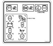


5 Decals (Wheel Loaders Only)


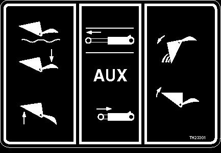
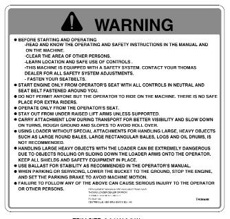


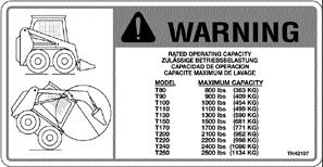
6 Decals

 36. 049734SP (R.H.")
7 Decals SP SP SP SP SP SP SP SP SP SP SP SP SP SP SP SP SP SP SP SP SP SP SP SP SP SP SP SP SP SP SP SP SP SP SP (Decal Kit) SP (R.H. Side) SP (L.H. Side)
8 1. MAINFRAME Fuel System Rear Door Universal Quick-Tach Lift Arms and Pivot Pins ROPS Assembly Boom Supports Shields Seat and Seat Belt Insulation (Standard) (A) Insulation (CE Models) (B) Fenders MAINFRAME 1
9 FUEL SYSTEM C C3846
10 ITEM PART QTY DESCRIPTION SP 1 Sender, Fuel Level SP 1 Gasket, for Fuel Sender SP 5 Screw SP 1 Fuel Cap SP 1 Locking Fuel Cap (Option)(Standard on CE Loaders) SP 1 Elbow SP 1 Reducer Bushing SP 1 Hose End SP 4 Clamp, Fuel Line SP 2 Clamp, Wire Hose SP A / R Hose, Fuel 3 3/ SP 1 Nipple SP 1 Fuel Filter Element SP A / R Hose, Fuel 5 5/ SP 1 Hose End SP 1 Shut Off Petcock SP 1 Elbow, 90º SP 1 Drain Plug SP 2 Nut, Hex SP 2 Bolt, Hex SP 2 Washer, Flat SP 2 Washer, Lock FUEL SYSTEM 1.1


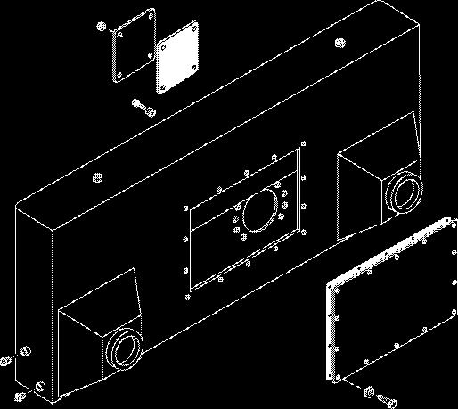
11 REAR DOOR C Rear Door - Looking at the Inside , 28, , 11, 12, C C3831
12 ITEM PART QTY DESCRIPTION * SP 1 Rear Door Complete SP 1 Rear Door Welded Assy SP 1 Plate, Door Guide SP 2 Bolt, Carriage 3/8 x SP 2 Washer, Flat 3/ SP 2 Nut, Nylok 3/ SP 2 Pin SP 2 Pin, Split Spring SP 2 Bearing SP 1 Sheet, Handle SP 1 Bolt, Hex 1/4 x SP 2 Washer, Nylon 1/4 x 7/ SP 1 Washer, Flat 1/ SP 1 Nut, Nylok 1/ SP 2 Clip, Rod Plastic SP 1 Rod,.161 Dia. x 2 w/#10-24 LH Thread SP 1 Turnbuckle, #10-24 Thread SP 1 Nut, Nylok # SP 1 Rod,.161 Dia. x 2 w/#10-24 RH Thread SP 1 Cylinder, Lock SP 1 Latch, Rotary LH SP 4 Bolt, Hex 1/4 x SP 4 Washer, Lock 1/ SP 1 Spring SP 1 Latch Cover Assembly SP 2 Bolt, Hex 1/4 x 3/ SP 2 Nut, Nylok 1/ SP 1 Bolt, Rotary Striker for Door Latch SP 1 Nut, Hex 7/ SP 1 Washer, Lock 7/ SP 2 Bearing REAR DOOR 1.2


13 UNIVERSAL QUICK-TACH C2649 C3077
14 ITEM PART QTY DESCRIPTION SP 1 Quick-Tach, Universal Assembly SP 2 Bolt, Hex SP 2 Pin (Hardened) SP 2 Nut, Nylok SP 2 Pin, Hardened Assy. * SP 2 Nut, Nylok SP 4 Grease Fitting SP 2 Plug SP 1 Plate, Handle RH * SP 1 Plate, Handle LH SP 2 Bushing, Hardened SP 2 Bar, Square, Linkage Block SP 2 Nut, Hex SP 2 Bushing, Spring Stabilizer SP 2 Spring SP 2 Bolt, Hex SP 1 Pin, Lock Assy. RH * SP 1 Pin, Lock Assy. LH SP 2 Bolt, Hex SP 4 Bushing, Stabilizer Bar SP 4 Washer, Flat SP 2 Washer, Belleville Spring SP 2 Bolt, Hex SP 2 Washer, Lock UNIVERSAL QUICK-TACH 1.3


15 LIFT ARMS and PIVOT PINS C C3840
16 ITEM PART QTY DESCRIPTION SP 1 Lift Arm, Painted Ass y W/Decals SP 1 Lift Arms Welded Assembly SP 2 Bushing, Hardened SP 2 Pin, Hardened SP 2 Bolt SP 2 Lock Nut SP 2 Pin, Hardened SP 8 Bolt SP 8 Lock Nut SP 2 Pivot Pin SP 2 Pivot Pin, Hardened SP 2 Lock Nut SP 4 Grease Fitting SP 2 Bushing, Hardened SP 2 Pin, Hardened SP 2 Pivot Pin, Hardened LIFT ARMS and PIVOT PINS 1.4


17 ROPS ASSEMBLY C C4570
18 ITEM PART QTY DESCRIPTION SP 1 ROPS Complete, Painted SP 1 ROPS Frame, Welded Assy (Rnd) SP 12 Screw, Hex Head SP 1 Window, Top SP 1 Window SP 6.25 ft Weatherstrip,Two Piece Self Sealing SP 6.25 ft Weatherstrip, Locking Strip SP A / R Weatherstrip (50 ft. roll) SP 4 Bar, ROPS Mounting Stud SP 4 Isolator, Neoprene SP 4 Snubbing Washer, ROPS SP 4 Washer, Lock SP 1 Plug, Buttonhole 7/ SP 1 Plug, Buttonhole 1/ SP 4 Nut, Nylok SP 1 Bolt, Hex SP 2 Washer, Snubbing SP 1 Isolator, Neoprene SP 1 Washer, Lock SP 1 Nut, Nylok SP 1 Manual Holder SP 3 Lock Nut SP 3 Washer SP 3 Washer SP 3 Bolt, Hex SP 28 Edging, Vinyl SP 12 5/8 Washer ROPS ASSEMBLY 1.5
19 BOOM SUPPORTS C C2019
20 ITEM PART QTY DESCRIPTION SP 2 Pin, Boom Support SP 2 Grease Fitting SP 2 Nut, Hex SP 2 Bar, Lock Pin Handle SP 2 Bolt, Hex SP 2 Washer, Lock SP 2 Washer, Flat SP 1 Spring SP 2 Knob, Tapered Red SP 1 Panel, Boom Support SP 2 Nut, Captive BOOM SUPPORTS 1.6
21 SHIELDS C (a) (b) C3838
22 ITEM PART QTY DESCRIPTION 1(a) SP 1 Step Shield Assy, Hand Controls 1(b) SP 1 Sheet, Step Shield, Foot Operated Controls SP 2 Bolt, Hex SP 4 Bolt, Hex SP 14 Washer, Lock SP 14 Washer, Flat SP 1 Spring, Gas 100 lb SP 2 Stud, Ball SP A/R Edging, Vinyl SP 8 Washer, Lock SP 8 Bolt, Hex SP 8 Washer, Flat SP 4 Nut, Captive SP 1 Shield, Front Step SP 1 Plate, Rear Access Cover SP 8 Bolt, Hex SP 2 Knob, Black w/ Brass Insert SP 2 Bar, Stud SP 1 Front Bulkhead Assembly SP 1 Sheet, Seat Mount SP 2 Bolt, Hex SP 1 Sheet, Clean Up Cover SP per/ft Foam weather strip SP 1 Engine Cover Assembly SP A/R Molding, Trim Seal SP per/ft Hose SP 4 Clamp, Tube Single SP 2 Plate, Cover Single SP 4 Washer, Flat SP 4 Screw, Hex Head SP 1 Sheet, Rear Shield SP 1 Knob With Stud SHIELDS 1.7
23 SEAT & SEAT BELT C C4571
24 ITEM PART QTY DESCRIPTION SP 1 Suspension Seat, Assembly w/o Logo SP 1 Sheet, Seat Mount Ass y SP 1 Harness, Seat Switch Wire SP 1 Switch, Seat SP 1 Knob, Black w/ Stud SP 1 Adjusters, Seat Rail Assy SP 2 Bolt, Hex SP 2 Washer, Flat SP 1 Nut, Nylok SP 1 Nut, Nylok SP 1 Washer, Flat SP 1 Bolt, Hex. 3/8 x 1 1/ SP 1 Washer, Flat SP 1 Belt, Safety 2 3 Point Retractable w/safety Wiring SP 1 Bolt, Hex Flange 1/2 x 1 1/2 SEAT & SEAT BELT 1.8
 1 3 2 16 4 C3202 5 14 15 13 6 12")
25 INSULATION (Standard) 1.9 (A) C C3891
26 ITEM PART QTY DESCRIPTION SP 1 Insulation, Headliner (*In Optional Kit) SP 1 Insulation, Left Rear Cornerpost (*In Optional Kit) SP 1 Insulation, Right Rear Cornerpost (*In Optional Kit) SP 1 Insulation, Lower Rear Window Panel (*In Optional Kit) SP 1 Insulation, Back Panel (*In Optional Kit) SP 1 Insulation, Battery Compartment Cover (*In Optional Kit) SP 1 Insulation, Outer Blanket SP 1 Insulation, Battery Box Blanket SP 1 Insulation, Right Side Panel (*In Optional Kit) SP 1 Insulation, ROPS Shield RH SP 1 Insulation, Front Frame SP 1 Insulation, Front Shield SP 1 Insulation, Front Bulkhead SP 1 Insulation, Seat Mount SP 1 Insulation, ROPS Shield LH SP 1 Insulation, Left Side Panel (*In Optional Kit) * Items in the optional Cab Liner Kit are also listed in Section INSULATION (Standard) 1.9 (A)
 1 25 3 2 17 (on tank) 4 16 21 18 (on tank) 20 5 14 15 13")
27 INSULATION (CE Models) 1.9 (B) (on tank) (on tank) C C4051
28 ITEM PART QTY DESCRIPTION SP 1 Insulation, Headliner SP 1 Insulation, Left Rear Cornerpost SP 1 Insulation, Right Rear Cornerpost SP 1 Insulation, Lower Rear Window Panel SP 1 Insulation, Back Panel SP 1 Insulation, Battery Compartment Cover SP 1 Insulation, Outer Blanket SP 1 Insulation, Battery Box Blanket SP 1 Insulation, Right Side Panel SP 1 Insulation, ROPS Shield RH SP 1 Insulation, Front Frame SP 1 Insulation, Front Shield SP 1 Insulation, Front Bulkhead SP 1 Insulation, Seat Mount SP 1 Insulation, ROPS Shield LH SP 1 Insulation, Left Side Panel SP 1 Insulation, Tank LH SP 1 Insulation, Cover Oil Tank SP 1 Insulation, Tank RH SP 2 Insulation, Shroud Bottom SP 1 Insulation, Shroud Top SP 1 Insulation, Rear Door LH Top SP 1 Insulation, Rear Door LH Bottom SP 1 Insulation, Rear Door RH SP 1 Insulation, Engine Cover INSULATION (CE Models) 1.9 (B)
29 FENDERS
30 ITEM PART QTY DESCRIPTION * U Kit, Fenders: SP 1 Fender, Welded Assy - LH * SP 1 Fender, Welded Assy - RH SP 6 Washer, Flat 5/ SP 6 Bolt, Hex Flange 1/2 x 3/4 FENDERS 1.10
31 WHEELS and TIRES 1.11 PART QTY DESCRIPTION SP 1 Kit, Tire 12 x 16.5, 2000 Series SP 2 Wheel & Tire Assy RH, 12 x 16.5, 8 Bolt SP 1 Tire, 12 x Series 8 Ply Tubeless SP 1 Wheel, x Bolt Negative (-) SP 1 Stem, Valve, Tubeless SP 2 Wheel & Tire Assy LH, 12 x 16.5, 8 Bolt SP 1 Tire, 12 x Series 8 Ply Tubeless SP 1 Wheel, x Bolt Negative (-) SP 1 Stem, Valve, Tubeless SP 32 Nut, Wheel
32 2. CONTROLS Control Levers - Hand Controls (A) Control Levers - Hand and Foot Controls...2.1(B) Foot Pedals - Hand and Foot Controls Throttle Restraint Bar CONTROLS 2
33 CONTROL LEVERS - Hand Controls 2.1(A) & C4167
34 ITEM PART QTY DESCRIPTION SP 2 Lever Retainer SP 2 Washer, Flat 1/ SP 2 Washer, Lock 1/ SP 4 Bushing, Flange 1 ID Nylon Split SP 2 Grease Fitting SP 1 Lever, RH Control Welded Assembly SP 1 Lever, LH Control Welded Assembly SP 4 Bushing, Flange 7/16 x 9/16 Oilite SP 2 Tube, Handle Spacer SP 2 Bolt, Hex 5/16 x SP 2 Nut, Nylok, Hex 5/ SP 2 Lever Base Welded Assembly SP 2 Bolt, Ergonomic Handle (With Hole) SP 2 Bolt, Hex (No Hole) SP 1 Handle, Ergonomic Plain SP 1 Handle, Ergonomic w/rocker & 2 PB Switches SP 2 Cable, Push/Pull SP 2 Clevis, 1/4 Pin SP 2 Pin, Clevis 1/4 x 3/ SP 2 Pin, Cotter 1/16 x 3/ SP 2 Rod End Assembly SP 1 Bolt, Hex 1/4 x 1 - RH SP 1 Bolt, Hex 1/4 x 1 1/2 - LH SP 2 Nut, Nylok 1/ SP 4 Rod End Assembly SP 4 Nut, Hex 7/ SP 2 Bolt, Hex 7/16 1 1/ SP 10 Washer, Lock 7/ SP 2 Nut, Nylok 7/ SP 2 Hex, Bolt 7/16 x SP 1 Bar, CF RD Linkage LH SP 1 Bar, CF RD Linkage RH SP 2 Hydroback Assembly SP 2 Bolt, Hex 3/8 1 1/ SP 4 Washer, 3/8 x 5/ SP 4 Nut, Nylok 3/ SP 2 Pintle Lever Assembly SP 4 Bolt, Hex 5/16 x SP 4 Nut, Nylok, Hex 5/ SP 1 Switch, Rocker SP 1 Cover, Rocker Switch Rubber CONTROL LEVERS - Hand Controls ITEM PART QTY DESCRIPTION SP 1 Bar, Spacer SP 1 Assembly, Control Cross Shaft SP 2 Bearing, Flanged, 2-Bolt SP 6 Bolt, Hex 5/16 x 1 1/ SP 4 Washer, Lock 5/ SP 1 Activator, RH Assembly SP 2 Bronze Bushing SP 1 Grease Fitting SP 2 Rod End Assembly SP 2 Nut, Nylok, Hex 5/ SP 2 Nut, Hex 5/ SP 2 Bar, Valve Control Rear SP 2 Nut, Hex 1/ SP 2 Pin, Cotter SP 2 Clevis SP 2 Pin, Clevis * SP 1 Sheet, Lever Boot Cover RH * SP 1 Sheet, Lever Boot Cover LH * SP 2 Boot, Rubbber Bellows, Control Lever * Items not shown. ** Hand Controls standard on CE models. 2.1(A)
35 CONTROL LEVERS - Hand and Foot Controls 2.1(B) & C4182
36 ITEM PART QTY DESCRIPTION SP 2 Lever Retainer SP 2 Washer, Flat 1/ SP 2 Washer, Lock 1/ SP 4 Bushing, Flange 1 ID Nylon Split SP 2 Grease Fitting SP 1 Lever, RH Control Welded Assembly SP 1 Lever, LH Control Welded Assembly SP 4 Bushing, Flange 7/16 x 9/16 Oilite SP 2 Tube, Handle Spacer SP 2 Bolt, Hex 1/4 x 1 3/ SP 2 Nut, Jam, Locking 1/ SP 2 Bolt, Hex, 5/16 x SP 2 Nut, Nylok, Hex 5/ SP 2 Lever Base Welded Assembly SP 2 Bolt, Ergonomic Handle (With Hole) SP 2 Bolt, Hex (No Hole) SP 1 Handle, Ergonomic Plain SP 1 Handle, Ergonomic w/rocker & 2 PB Switches SP 4 Rod End Assembly (Hand Control Loaders) SP 4 Nut, Hex 7/ SP 2 Bolt, Hex 7/16 x 1 1/ SP 10 Washer, Lock 7/ SP 2 Nut, Nylok 7/ SP 2 Hex, Bolt 7/16 x SP 1 Bar, CF RD Linkage LH SP 1 Bar, CF RD Linkage RH SP 2 Hydroback Assembly SP 2 Bolt, Hex 3/8 x 1 1/ SP 4 Washer, 3/8 x 5/ SP 4 Nut, Nylok 3/ SP 2 Pintle Lever Assembly SP 4 Bolt, Hex 5/16 x SP 4 Nut, Nylok, Hex 5/ SP 1 Switch, Rocker SP 1 Cover, Rocker Switch Rubber * SP 1 Sheet, Lever Boot Cover RH * SP 1 Sheet, Lever Boot Cover LH * SP 2 Boot, Rubber Bellows, Control Lever * Items not shown. CONTROL LEVERS - Hand and Foot Controls 2.1(B)


37 FOOT PEDALS - Hand and Foot Controls C C4181
38 ITEM PART QTY DESCRIPTION SP 2 Bar, Foot Pedal Shaft SP 2 Screw SP 1 Grease fitting SP 1 Pedal, Lift Assy SP 1 Pedal, Tilt Assy SP 4 Bolt, Hex SP 8 Nut, Nylok SP 6 Rod End Assy SP 6 Nut, Hex SP 2 Bar, Valve Control Front SP 2 Bearing, Flanged, 2-Bolt SP 2 Pin, Cotter SP 4 Bolt, Hex SP 4 Washer, Lock SP 1 Activator, RH Assy SP 2 Bronze Bushing SP 2 Bolt, Carriage SP 1 Assy, Control Cross Shaft SP 2 Bar, Valve Control Rear SP 2 Nut SP 2 Clevis SP 2 Pin, Clevis SP 2 Dampener, Self Centering SP 2 Lock Washer * SP 1 Bolt, Hex (Rear Limiter Bolt) * SP 1 Bolt, Hex (Front Limiter Bolt) * SP 2 Nut, Hex (for Limiter Bolts) * Items not shown in diagram. FOOT PEDALS - Hand and Foot Controls 2.2
39 THROTTLE 2.3 C C3343
40 ITEM PART QTY DESCRIPTION SP 1 Cable, Turn-to-Lock SP 1 Joint, Ball Socket SP 1 Throttle Bracket Assy SP 2 Bolt, Hex SP 2 Washer, Lock SP 2 Washer, Flat SP 1 Nut SP 1 Nut, Jam THROTTLE 2.3
41 RESTRAINT BAR C C1181
42 ITEM PART QTY DESCRIPTION SP 1 Restraint Bar Assy SP 2 Nut, Nylok SP 2 Stud, Ball SP 1 Gas, Spring SP 1 Switch, Dual SP 2 Screw, Machine SP 2 Washer, Lock SP 1 Nut, Jam SP 2 Spacer SP 1 Lockwasher RESTRAINT BAR 2.4
43 3. FINAL DRIVE TRANSMISSION Transmission Housing Axle Assembly FINAL DRIVE TRANSMISSION 3
44 TRANSMISSION HOUSING C C4724
45 ITEM PART QTY DESCRIPTION SP 1 Transmission Welded Assembly, RH SP 1 Transmission Welded Assembly, LH SP 10 Nut, Hex Flanged SP 1 Gasket, Transmission Inspection Cover SP 4 Sheet, Axle Cover SP 2 Plug, Vented SP 2 Bushing, Breather Reducing SP 4 Plug, Drain SP 4 Washer, Nylon SP 2 Sheet, Cover, Wheeled Version SP 4 Gasket, Transmission Axle cover SP 40 Bolt, 5/8 x 1 UNC SP 40 Washer, Lock, 5/8 * Diagram shows LH side of Transmission Housing only. TRANSMISSION HOUSING 3.1
46 AXLE ASSEMBLY C C4151
47 ITEM PART QTY DESCRIPTION SP 1 Axle Assembly (4 required) SP 1 Seal SP 8 Nut, Wheel SP 8 Stud, Wheel SP 1 Bearing, Cone SP 2 Bearing, Cup SP 1 Plate, Axle Spacer SP 1 Sprocket, 27T100 Axle, Front SP 1 Sprocket, 27T100 Double Rear Axle SP 1 Plate, Axle Washer SP 1 Nut, Castle SP 1 Pin, Cotter SP 1 Sheet, Axle Cover SP 4 Nut, Hex, Flange SP 1 Bearing, Cone SP 1 Axle Puller SP 2 Seal Installation Tool, 2 Required SP 1 Gasket, Transmission Axle cover SP 1 Plate, Axle Seal Protector SP 2 Screw, Cap 1/4 UNC SP 2 Washer, Lock 1/4 PL Chains and Connecting Links (per side) * SP 1 Chain, RS100H Solid Roller, 66 Pitches (Wheel Option) * SP 1 Chain, RS100H Solid Roller, 52 Pitches (Wheel Option) * SP 2 Connecting, Link, #100H (Wheel Option) * SP 1 Chain, RS100H Double Standard, SLD Roller (Track Loader) * SP 1 Conn. Link #100 Double Standard (Track Loader) ** Quantities listed are per axle assembly. AXLE ASSEMBLY 3.2
48 4. HYDRAULIC SYSTEM Oil Reservoir Hydraulic Oil Filter Boom Lift Circuit (Standard) (A) Boom Lift Circuit (w/ Optional Self Level Valve) (B) Fan / Radiator / Oil Cooler Lift Cylinder Bucket Tilt Circuit (Standard) (A) Bucket Tilt Circuit (w/ Optional Self Level Valve) (B) Tilt Cylinder Auxiliary Circuit Control Valve Accumulator Flat Face Coupling HYDRAULIC SYSTEM 4
49 OIL RESERVOIR (To pump drain) C (To drain tee) (Cooler return runs to oil filter, then this hose runs from filter) (To charge pump inlet) (To gear pump) C3850
50 ITEM PART QTY DESCRIPTION SP 1 Pressurized Filler Cap SP 1 Element, Hydraulic Oil Suction SP 1 Heater, Hydraulic Oil (Optional) SP 1 Gasket, Oil Tank Inspection Cover SP 2 Elbow, SP 2 Clamp, Circle Two Ear SP ft. Tube, Clear Vinyl SP 1 Sheet, Baffle Top SP 1 Sheet, Baffle Bottom SP 1 Magnet, Hydraulic Oil Tank SP 1 Bushing. Reducing SP 1 Switch, Temperature Sender SP 1 Connector SP 1 Hose, Hydraulic 1 x 56 (Tank to gear pump) SP 1 Plug, Socket Head Magnetic Pipe SP 1 Tee, Branch SP 1 Hose, Hydraulic 3/4 x 22.5 (Filter outlet to tee in tank) SP 1 Hose, Hydraulic 1 x 52 (Tee in tank to charge inlet) SP 1 Cover, Inspection Hole SP 12 Nut, Hex Flange SP 1 Elbow, SP 1 Hose, Hydraulic 1/2 x 73 (Drain tee to tank) SP 1 Elbow, SP 1 Hose, Hydraulic 3/4 x 63 (Pump drain to tank) SP 4 Clamp SP 2 Clamp Plate SP 1 Washer, Lock SP 1 Bolt SP 1 Plug, Socket Head Magnetic OIL RESERVOIR 4.1
51 HYDRAULIC OIL FILTER C To Tank C3325
52 ITEM PART QTY DESCRIPTION SP 1 Filter, Hydraulic Assy SP 2 Element, Hydraulic Oil Filter SP 1 Head, Filter Hydraulic Assy SP 2 Elbow, 90º SP 1 Hose, Hydraulic (Filter outlet to tee in tank) SP 1 Hose, Hydraulic (Cooler top to filter inlet) SP 8 Bolt, Hex SP 8 Washer, Lock SP 8 Washer, Flat SP 1 Filter, Hydraulic Assy SP 1 Element, Hydraulic Oil Filter SP 1 Head, Filter Assy. HYDRAULIC OIL FILTER 4.2
53 BOOM LIFT CIRCUIT (Standard) 4.3 (A) C C3326
54 ITEM PART QTY DESCRIPTION 1. *** 2 Lift cylinder, see section SP 2 Hose, Hydraulic (Lift cylinder front port to rear bulkhead) SP 2 Hose, Hydraulic (Lift cylinder rear port to front bulkhead) SP 2 Lock nut SP 2 Tee SP 2 Connector, Bulkhead 90º SP 2 Hose, Hydraulic (Lift hoses from bulkheads to bulkheads) SP 4 Washer, Lock Internal Tooth SP 2 Connector, Bulkhead 90º SP 1 Hose, Hydraulic (Lift rear port to front bulkhead) SP 1 Hose, Hydraulic (Lift front port to rear bulkhead) SP 2 Elbow, 90º 13. *** 1 Control valve, see section SP 2 Bolt SP 2 Plate, Cover Twin SP 4 Clamp SP of Tube, Heli 3/4 x3/4 (Used to wrap hoses on the liftarms) BOOM LIFT CIRCUIT (Standard) 4.3 (A)
 1 2 3 17 16 14 17 16 20 4 16 15 18 C3081 2 3 8 6 16 15 14 19 7 7 5 5 8 9 11 8 9 6 12")
55 BOOM LIFT CIRCUIT (w/ Optional Self Level Valve) (Standard on CE Models) 4.3 (B) C C3841
56 ITEM PART QTY DESCRIPTION 1. *** 2 Lift cylinder, see section SP 2 Hose, Hydraulic (Lift cylinder front port to rear bulkhead) SP 2 Hose, Hydraulic (Lift cylinder rear port to front bulkhead) SP 1 Hose, Hydraulic (SLV port A to rear bulkhead) SP 2 Tee SP 2 Connector, Bulkhead 90º SP 2 Hose, Hydraulic (Lift hoses from bulkheads to bulkheads) SP 4 Washer, Lock Internal Tooth SP 2 Connector, Bulkhead 90º SP 1 Hose, Hydraulic (Lift rear port to front bulkhead) SP 1 Hose, Hydraulic (Valve front port to SLV port B ) SP 2 Elbow, 90º 13. *** 1 Control valve, see section SP 2 Bolt SP 2 Plate, Cover Twin SP 4 Clamp SP 2 Lock nut SP 1 Valve, Self Level Assy SP 1 Connector SP 1 Elbow, 90º * The Self Level Valve is standard on CE loaders. BOOM LIFT CIRCUIT (w/ Optional Self Level Valve) (Standard on CE Models) 4.3 (B)

57 FAN / RADIATOR / OIL COOLER C4572
58 ITEM PART QTY DESCRIPTION SP 1 Rad / Cooler Assembly SP 2 Plate, Rad Mount Left SP 2 Plate, Rad Mount Right SP 4 Bearing SP 2 Bar, Rad Pin SP 2 Clip, Hairpin-Plated SP 8 Bolt, Hex 3/8 x 1 1/ SP 8 Washer, Flat 3/ SP 8 Nut, Nylok 3/ SP 2 Bolt, Hex 1/2 x SP 4 Washer, Flat 1/ SP 2 Nut, Nylok 1/ SP 1 Fan Guard Welded Assembly SP 1 Sheet, Bolt On Shield SP 2 Bar, Standoff Bottom SP 5 Washer SP 3 Isolator, Neoprene SP 3 Nut, Nylok 3/ SP 2 Washer, Lock 3/ SP 4 Washer, Flat 1/ SP 4 Nut, 1/4 Flange SP 1 Washer, Flat 3/ SP 1 Plate, Fan Guard Brace SP 1 Bolt, Hex 3/8 x 2 1/ SP 6.5 ft. Molding, Trim Seal 3/4 x 1/ SP 1 Shroud, Welded Assembly SP 5 Bolt, Hex 5/16 x SP 10 Washer, Flat 5/ SP 5 Nut, Nylok, Hex 5/ SP 1 Fan, Multiwing SP 96 Weatherstrip, 5/16 x 3/ SP 2 Bolt, Hex SP 2 Washer, Lock SP 2 Clamp, Hose # SP 1 Hose, Top Radiator SP 1 Hose, Coolant Bottom SP 1 Hose, Hydraulic (Cooler top to filter inlet) ITEM PART QTY DESCRIPTION SP 1 Hose, Hydraulic (Cooler bottom to Control Valve) SP 2 Elbow, 90º FAN / RADIATOR / OIL COOLER 4.4
59 LIFT CYLINDER C C2783
60 ITEM PART QTY DESCRIPTION SP 1 Cylinder Assembly (pair required) SP 1 Kit, Seal Hydraulic Cylinder SP 1 Spacer SP 1 Nut, Lock SP 1 Grease Fitting, 90º SP 1 Grease Fitting Straight SP 1 Bushing, Hardened LIFT CYLINDER 4.5
 1 2 C3082 2 16 17 18 15 14 13 13 4 3 12 5 6 14 7 18 17")
61 BUCKET TILT CIRCUIT (Standard) 4.6 (A) 1 2 C C3327
62 ITEM PART QTY DESCRIPTION 1. *** 2 Tilt Cylinder, See Section SP 4 Hose, Hydraulic (Tilt cylinder to tube) SP 1 Tube, Hydraulic (Inside tilt tube) SP 1 Tube, Hydraulic (Outside tilt tube) SP 1 Hose, Hydraulic (Front bulkhead to inside hydraulic line) SP 1 Hose, Hydraulic (Rear bulkhead to outside hydraulic line) SP 1 Connector, Bulkhead 90º SP 1 Connector, Bulkhead 90º (Long) SP 2 Hose, Control Valve to Bulkhead SP 2 Connector 11. *** 1 Control Valve, See Section SP 2 Star washer SP 4 Clamp, Tube Twin 5/ SP 4 Plate, Cover Twin SP 4 Nut, Nylok SP 2 Nut, Nylok SP 4 Plate, Cover Twin SP 4 Clamp, Twin 3/4 Tube SP 2 Bolt, Hex BUCKET TILT CIRCUIT (Standard) 4.6 (A)
 1 2 C3082 26 25 24 4 6 2 5 17 24 25 26 18 19 20 21 13 7 3 8 22 1 16 15 12 9 14 11")
63 BUCKET TILT CIRCUIT (w/ Optional Self Level Valve) (Standard on CE Models) 4.6 (B) 1 2 C C3844
64 ITEM PART QTY DESCRIPTION 1. *** 2 Tilt Cylinder, See Section SP 4 Hose, Hydraulic (Tilt cylinder to tube) SP 1 Tube, Hydraulic (Inside tilt tube) SP 1 Tube, Hydraulic (Outside tilt tube) SP 1 Hose, Hydraulic (Front bulkhead to inside hydraulic line) SP 1 Hose, Hydraulic (Rear bulkhead to outside hydraulic line) SP 1 Connector, Bulkhead 90º SP 1 Connector, Bulkhead 90º (Long) SP 1 Hose, Hydraulic (Front valve port to SLV Port D ) SP 1 Hose, Hydraulic (Rear valve port to SLV Port C ) SP 1 Connector, Straight SP 1 Hose, Hydraulic (SLV Port C, tee to rear bulkhead) SP 1 Hose, Hydraulic (SLV Port D, tee to front bulkhead) SP 1 Tee SP 1 Valve, Self Level Assembly (SLV) SP 2 Bolt, Hex SP 2 Bar SP 2 Washer, Flat SP 2 Washer, Lock SP 2 Nut, Hex SP 1 Tee SP 2 Star Washer 23. *** 1 Control Valve, See Section SP 4 Clamp, Tube Twin 5/ SP 4 Plate, Cover Twin SP 4 Nut, Nylok SP 1 Elbow * The Self Level Valve is standard on CE loaders. BUCKET TILT CIRCUIT (w/ Optional Self Level Valve) (Standard on CE Models) 4.6 (B)
65 TILT CYLINDER C C2676
66 ITEM PART QTY DESCRIPTION SP 1 Tilt Cylinder (pair required) SP 1 Kit, Seal, Hydraulic Cylinder SP 1 Bushing, Hardened SP 1 Nut, Cylinder, Hex SP 1 Fitting, Grease (Straight) SP 1 Fitting, Grease (90º) TILT CYLINDER 4.7
67 AUXILIARY CIRCUIT C3913
68 ITEM PART QTY DESCRIPTION 1. *** 1 Control Valve, see Section SP 1 Elbow, 90º SP 1 Tube, Hydraulic (Bulkhead to valve) SP 1 Tube, Hydraulic (Bulkhead to valve) SP 1 Connector, Bulkhead 90º (Long) * SP 2 Internal Star Washer (used on bulkheads) SP 1 Hose, Hydraulic (Rear bulkhead to outside hydraulic lines) SP 1 Hose, Hydraulic (Front bulkhead to inside hydraulic lines) SP 1 Connector, Bulkhead 90º SP 2 Elbow, 90º SP 2 Bolt SP 4 Clamp, Tube Twin SP 2 Plate, Cover Twin SP 1 Tube, Hydraulic (Inside auxiliary tube) SP 1 Tube, Hydraulic (Outside auxiliary tube) SP 2 Connector, Bulkhead SP 1 Coupling, Quick Disconnect, Female SP 1 Dust Cap for Female Quick Coupler SP 1 Coupling, Quick Disconnect, Male SP 1 Dust Cap for Male Quick Coupler SP 2 Lock Washer SP 1 Connector AUXILIARY CIRCUIT 4.8
69 CONTROL VALVE (a) (b) C3875
70 ITEM PART QTY DESCRIPTION SP 1 Valve, Hyd Assy Sol Aux w/control Boxes SP 1 Valve, Main Relief SP 1 Kit, Lift Circuit w/o Spool SP 1 Kit, Tilt Circuit w/o Spool SP 1 Kit, Aux Circuit w/o Spool SP 2 Kit, Control Lever Box SP 3 Valve, Check SP 4 Plug, Anti-Cav. Replacement SP 1 Valve, Anti-Cavitation SP 1 Valve, Port Relief SP 2 Bar, Control Lever Linkage SP 2 Screw, Set SP 1 Kit, Dust Cap w/connector for Hand Control (Optional) SP 1 Coil, Solenoid Lock Assy SP 1 Coil, Auxiliary Solenoid SP 1 Bar, Control Lever Linkage (Hand Control Option) SP 2 Nut, Jam SP 1 Seal Kit * On hand control units, the quantity of control lever linkage bars (#11) will change from 2 to 1. ** Hand Controls are standard on CE models. CONTROL VALVE 4.9
71 ACCUMULATOR (To tandem pump gauge port tee) 18 C
72 ITEM PART QTY DESCRIPTION SP 1 Accumulator, Diaphragm SP 1 Sheet, Accumulator Mount Top SP 1 Sheet, Accumulator Mount Bottom SP 4 Nut, Nylok, Hex 5/ SP 4 Washer, Flat 5/ SP 1 Tee, Run SP 1 Hose, Hydraulic 3/8 x 31 (Control valve to accumulator tee) SP 1 Hose, Hydraulic 3/8 x 7 (Accumulator tee to check valve) SP 1 Hose, Hydraulic 3/8 x 57 (Check valve tee to charge pump gauge port tee) SP 1 Connector, Male SP 1 Valve, Check SP 1 Tee, Run SP 1 Hose, Hydraulic 1/4 x 15 (Check valve tee to quick disconnect bulkhead) SP 1 Connector, Bulkhead SP 1 Coupling, Quick Disconnect Male SP 1 Dust Plug, Quick Disconnect Male 17. *** 1 Control Valve, See Section SP 1 Connector, Male SP 1 Elbow, SP 4 Washer, Lock ACCUMULATOR 4.10
73 FLAT FACED COUPLING 4.11 PART QTY DESCRIPTION U Kit, Coupling Flat Face: SP 1 Coupling, Quick Disconnect Female, 8 1/2 NPTF Flush Face Type 3/ SP 1 Coupling, Quick Disconnect Male, 8 1/2 NPTF Flush Face Type 3/ SP 1 Cap, Dust for Female Flush Face Coupling SP 1 Cap, Dust for Male Flush Face Coupling
74 5. HYDROSTATIC DRIVE SYSTEM Hydrostatic Drive Circuit Hydrostatic Tandem Pump Hi-Flow Circuit Torque Motor HYDROSTATIC DRIVE SYSTEM 5

 29 29 19 41 50 10 4")
75 HYDROSTATIC DRIVE CIRCUIT (To Tee in Tank) 13 (To Check Valve) (To Control Valve Inlet) (To Tank) 17 (To Tank) (To Tank) C4725
76 ITEM PART QTY DESCRIPTION ITEM PART QTY DESCRIPTION SP 1 Pump, Tandem Assembly 245 bar SP 1 Hose, Hydraulic 3/8 x 16 (Brake valve port SP SP 1 1 Pump, Gear Hose, Hydraulic 1 1/4 x SP 1 to LH motor brake release port Z) Hose, Hydraulic 3/8 x SP 1 (Tank to gear pump) Hose, Hydraulic 3/4 x SP 2 (LH motor case drain to brake valve port 4) Motor, Hydraulic Assembly 680 cc (Tandem pump drain to tank) SP 1 Valve, 2 pos 4 way w/check man override SP 1 Hose, Hydraulic 3/8 x 22 Hi Pressure SP 1 Elbow, 90 (Gauge ports to tee in front motor ports) SP 1 Elbow, SP 1 Hose, Hydraulic 3/4 x SP 1 Elbow, 90 (Bottom of rear pump to RH motor front) SP 1 Elbow, SP 1 Hose, Hydraulic 3/4 x SP 1 Tee, Branch (Top of rear pump to RH motor rear) SP 2 Connector, Male SP 1 Hose, Hydraulic 5/8 x SP 1 Elbow, 90 (Gear pump to valve) SP 1 Tee, Run SP 1 Hose, Hydraulic 3/4 x SP 2 Connector, Male (Bottom of front pump to LH motor front) SP 1 Tee, Run SP 1 Hose, Hydraulic 3/4 x SP 1 Elbow, 90 (Top of front pump to LH motor rear) SP 1 Tee, Branch SP 1 Hose, Hydraulic 1 x SP 1 Elbow, 90 (Tee in tank to change inlet) SP 1 Elbow, SP 1 Hose, Hydraulic 3/8 x 54 (Tee at pump SP 1 Tee, Branch charge gauge port to brake valve port 2) SP 1 Cap SP 1 Hose, Hydraulic 3/8 x 57 (Check valve tee SP 1 Elbow, 90 to charge pump gauge port tee) SP 2 Tee, Branch SP 1 Hose, Hydraulic 3/8 x SP 2 Elbow, 90 (Gauge port to tee in front motor port) SP 2 Connector SP 1 Hose, Hydraulic 3/8 x SP 2 Elbow, 90 (LH motor case drain to RH motor case drain) SP 1 Elbow, SP 1 Hose, Hyd. 3/8 x 11 (LH motor brake release SP 1 Connector, Male port Z to RH motor brake release port Z) * SP 2 Plug, Hex Head (Located under torque motors) SP 1 Hose, Hydraulic 1/2 x 73 (Tank drain to LH motor case drain) SP 1 Hose, Hyd. 1/4 x 13 (LH motor active brake * Items not shown in diagram. port X to RH motor active brake port X) SP 1 Hose, Hydraulic 3/8 x 13 (Brake valve port 3 to LH motor active brake port X) HYDROSTATIC DRIVE CIRCUIT 5.1
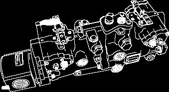
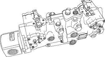
77 HYDROSTATIC TANDEM PUMP C3456
78 ITEM PART QTY DESCRIPTION SP 1 Pump, Tandem Assembly 345 bar SP 1 Pump, Gear * SP 1 Kit, Seal Servo Pump * SP 1 Kit, Seal, Gear Pump, 29cc E-Series HYDROSTATIC TANDEM PUMP 5.2

79 HI - FLOW CIRCUIT 5.3 C4594
80 ITEM PART QTY DESCRIPTION SP 1 Cap, Dust for Female Flush Face Coupling SP 1 Coupling, Quick Disconnect, Female, Flush Face SP 1 Connector, Bulkhead SP 1 Hose, Hydraulic 1/2 x 83 5/8 (Attachment return) SP 2 Hose, Hydraulic 3/4 x 87 7/16 (Tank bulkheads to quick couplers) SP 1 Elbow, SP 2 Connector, Bulkhead SP 1 Coupling, Quick Disconnect, Male, Flush Face SP 1 Cap, Dust for Male Flush Face Coupling SP 1 Coupling, Quick Disconnect, Female, Flush Face SP 1 Cap, Dust for Female Flush Face Coupling SP 1 Hose, Hydraulic 3/4 x /16 (Hi-flow valve to oil cooler inlet) SP 1 Valve, Hydraulic Manifold 255 Hi-Flow SP 3 Connector SP 2 Elbow, SP 2 Connnector, Bulkhead SP 1 Tee, Run SP 1 Hose, Hydraulic 3/4 x 75 15/16 (Control valve to hi-flow valve P1) SP 1 Radiator/Oil Cooler Assy SP 1 Hose, Hydraulic 3/4 x 84 (Cooler to filter inlet) SP 1 Valve, Hyd, Assy Sol Aux w/control Boxes SP 1 Hose, Hydraulic 5/8 x 57.5 (Gear Pump to valve) SP 1 Plug, Power Beyond SP 1 Connector, Bulkhead SP 1 Hose, Hydraulic 1 1/4 x 61 (Tank to gear pump inlet) SP 1 Hose, Hydraulic 3/4 x 75 3/8 (Gear pump outlet to hi-flow valve P2) SP 1 Elbow, SP 1 Elbow, SP 1 Hose, Hydraulic 1/2 x 51 3/4 (Control valve T port to tank) SP 1 Pump, Gear Double 29/29CC SP 1 Filter, Hydraulic Assy SP 1 Hose, Hydraulic 3/4 x 22.5 (Filter outlet to tank) SP 1 Tee, Branch SP 1 Hose, Hydraulic 3/4 x 20 15/16 (Port A of hi-flow valve to bulkhead) SP 1 Hose, Hydraulic 3/4 x 19 15/16 (Port B of hi-flow valve to bulkhead) SP 1 Elbow, G-Pump Suction Hose At Tank HI - FLOW CIRCUIT 5.3

81 TORQUE MOTOR C3756
82 ITEM PART QTY DESCRIPTION (per motor) SP 1 Motor, Hydraulic Assy 750/410 cc, 2 required SP 7 Bolt, Hex 5/8 x 2 1/ SP 15 Nut, Hex 5/ SP 1 Sprocket, Drive 12T100 DS (Wheel Option) SP 1 Sprocket, Drive (Track Option) SP 1 Sheet, Retaining Washer SP 1 Washer, Lock SP 1 Bolt, Hex SP 1 Bolt, Hex 5/8 x 2 * SP 1 Seal Kit * SP 1 Kit, Brake Service * SP 1 Shaft Seal * SP 1 Shaft Seal Insertion Tool * SP 1 Brake External Seal Insertion Tool * Items not shown. TORQUE MOTOR 5.4
83 6. ELECTRICAL SYSTEM Electrical Wiring, ROPS Electrical Wiring, Engine ELECTRICAL SYSTEM 6


84 ELECTRICAL WIRING, ROPS 6.1 C C3889
85 ITEM PART QTY DESCRIPTION SP 1 Harness, ROPS Assy SP 1 Indicator Light, Low Charge Pressure SP 1 Indicator Light, Brake SP 1 Indicator Light, Battery SP 1 Indicator Light, Preheat SP 1 Indicator Light, Air Filter SP 1 Indicator Light, Hydraulic Oil Temperature SP 1 Indicator Light, Coolant Temperature SP 1 Indicator Light, Engine Oil Pressure SP 1 Indicator Light, Directional Indicator LH SP 1 Indicator Light, Directional Indicator RH SP 1 Indicator Light, Hi-Flow Hydraulics SP 1 Indicator Light, Auxiliary Hydraulics SP 1 Indicator Light, Lights Dipped Low Beam SP 1 Indicator Light, Seat Belt SP 1 Indicator Light, Beacon SP 1 Switch, Toggle SPST (Headlights) SP 1 Switch, Toggle DPST (Auxiliary Hydraulics) SP 1 Hour Meter SP 1 Fuel Gauge SP 1 Ignition Switch * SP 1 Key, Steel, Ignition (Pair) SP 2 Lamp, Oval * SP 1 Oval Light Mounting Bracket Assy. LH * SP 1 Oval Light Mounting Bracket Assy. RH * SP 2 Harness, Wire Oval Lamp SP 1 Horn (Optional) SP 1 Panel, LH Instrument Assy SP 1 Panel, RH Instrument Assy. Harness Clamps * SP 1 Clamp, #8 * SP 4 Clamp, #12 * SP 2 Clamp, #18 * Items not shown. ELECTRICAL WIRING, ROPS 6.1

86 ELECTRICAL WIRING, ENGINE C (Fuel Shutoff Connector installed at Thomas Plant) C4153
87 ITEM PART QTY DESCRIPTION SP 1 Harness, Engine Wire SP 1 Starter, Engine V3300T SP 1 Alternator, 60A, Internal Regulator SP 1 Glow Plug, Steel, V3300T SP 1 Solenoid, Engine Stop V3300T SP 1 Indicator, Service Electrical (Air) SP 1 Switch, Temperature Sender, 12 Volt (Hyd. Oil Temp.) SP 1 Switch, Oil (Engine Oil Pressure) SP 1 Sender, Fuel Level SP 1 Switch, Temperature Sender, 12 Volt (Water Temp.) SP 3 Relay, 12V 40A SPDT Form C c/w Bracket SP 1 Panel, Fuse * SP A/R Fuse, Automotive, 15 Amp (5 per pack) * SP A/R Fuse, Automotive, 10 Amp (5 per pack) 13. *** 1 See Section SP 1 Handle, Ergonomic w/ Rocker & 2 PB Switches * SP 1 Switch, Rocker * SP 1 Cover, Rocker Switch Cover SP 1 Cable, Battery Assy. Dual w/ Boosting Cable SP 2 Battery, CCA 730 Dual Terminal 12V w/handle SP 1 Switch, Dual c/w Bracket 18. *** 1 See Section SP 1 Switch, Seat, Quick Mount Normally Open SP 1 Switch, Contact Body Assy. (Stop Button) (Optional) SP 2 Cable, Ground SP 1 Rear Work Light SP 1 Handle, Ergonomic Plain SP 1 Box, Electrical Assy SP 1 Knob, Black w/ Stud SP 1 Lug, External Boosting SP 1 Harness, Two Speed SP 1 Control, Shift w/relay SP 1 Light, Indicator 2 Speed * SP 1 Harness, Mainframe * SP 1 Harness, Wire Lighting (CE only) * SP 1 Alarm, Back-Up (Optional) * SP 1 Switch, Back-Up Alarm (Optional) ELECTRICAL WIRING, ENGINE 6.2
88 7. ENGINE EQUIPMENT Air Cleaner Exhaust System Engine Accessories Engine ENGINE EQUIPMENT 7
89 AIR CLEANER C C4114
90 ITEM PART QTY DESCRIPTION SP 1 Cleaner, Air Assembly SP 1 Foam, Air Intake Gasket SP 1 Foam, Air Cleaner Seal SP 1 Indicator, Restrictor Elect SP 1 Hose, Molded Air Intake Part A SP 1 Tube SP 1 Clamp, Hose # SP 2 Clamp, Hose # SP 1 Hose, Molded Air Intake Part B SP 1 Element, Fiber Inner Air (Safety) SP 1 Element, Paper, Outer Air (Primary) SP 1 Clamp, Hose # SP 1 Vacuator SP 3 Bolt, Hex SP 3 Washer, Lock SP 1 Air Cleaner Mount SP 4 Bolt, Hex SP 4 Washer, Lock SP 1 Cover, Plastic, Air Cleaner SP 1 Precleaner, 4 inlet w/gasket for 3.75 inlet AIR CLEANER 7.1
91 EXHAUST SYSTEM C C3339
92 ITEM PART QTY DESCRIPTION SP 1 Muffler, Assy SP 1 Muffler, Assy w/ Tailpipe Insulated (CE Only) SP 1 Gasket, Steel, Muffler SP 4 Nut SP 4 Lock washer SP 2 Bolt, Hex SP 2 Washer, Lock SP 2 Nut, Hex SP 1 Muffler Support Assy. EXHAUST SYSTEM 7.2

93 ENGINE ACCESSORIES C4596
94 ITEM PART QTY DESCRIPTION SP 1 Radiator Assy SP 1 Cap, Steel, Radiator SP 1 Clamp SP 6 ft. Hose, Fuel SP 3 Clamp, Hose # SP 1 Hose, Top Radiator (S/N LR onward) SP 1 Hose, Coolant Bottom SP 2 Clamp, Fuel Line SP 1 Reservoir, Coolant * SP 1 Cap, Over Flow Jug SP 1 Fuel Filter SP 1 Filter, Engine Oil, V3300T SP 2 Nut, Flange SP 1 Belt, Rubber V V3300T (Standard - S/N LR onward) SP 1 Belt, V (CE Models - S/N LR onward) SP 2 Bolt, Hex Socket Head SP 8 Nut, Hex SP 1 Tube, Dipstick SP 1 Kit, Adapter SP 28 Washer, Lock SP 8 Bolt SP 16 Bolt, Hex SP 4 Bolt SP 1 Pump Support Assy SP 1 Mount, LH Rear Assy SP 1 Mount, RH Rear Assy SP 16 Washer, Lock SP 16 Bolt, Hex SP 4 Bolt, Hex SP 2 Front Mount Assy SP 4 Isolator, Engine SP 4 Washer, Overload SP 4 Washer, Rebound ITEM PART QTY DESCRIPTION SP 4 Washer, Lock SP 4 Nut, Hex SP 1 Clamp, Hose #32 (S/N LR onward) SP 1 Pulley, V 130 mm Dia SP 1 Pulley, V 154 mm Dia. (CE Models) SP 1 Hose, Hydraulic (Cooler top to filter inlet) SP 1 Hose, Hydraulic (Cooler bottom to Control Valve) SP 2 Elbow, 90º SP 1 Cooler Ass y * SP 1 Thermostat, Steel, V3300T * SP 1 Gasket, Fiber, Thermostat, V3300T * SP 4 Nozzle, Steel, V3300T * SP 4 Copper Seal Washer (for Injector) * Item not shown ENGINE ACCESSORIES 7.3


95 ENGINE & C3457
96 ITEM PART QTY DESCRIPTION SP 1 Engine Assembly V3300T SP 1 Alternator, 60A, Internal Regulator SP 1 Starter, Engine SP 4 Glow Plug, Steel SP 1 Gasket, Fiber, Thermostat SP 1 Gasket, Steel, Muffler SP 4 Nozzle, Steel SP 1 Thermostat, Steel SP 1 Filter, Engine Oil SP 1 Belt, Rubber V (Standard - S/N LR onward) SP 1 Belt, V (CE Models - S/N LR onward) SP 1 Solenoid, Engine Stop SP 1 Hose, Crossover * SP 14 L Oil, SAE 5W40 API-CF * Item not shown in diagram. ** Items 3, 6 and 10 highlight items actually found on the other side of the engine and can not be seen by this view. ENGINE 7.4
97 8. TRACKS Track Assembly Locking Arms Tandem Supports Idler Assembly TRACKS 8

98 TRACK ASSEMBLY (R.H. SIDE SHOWN) C4726
99 ITEM PART QTY DESCRIPTION SP 1 Track Kit Complete SP 1 Track SP 2 Track Wheel Mount SP 3 Reinforcement Plates SP 3 Section Of Track Wheel SP 1 Trackwheel, Solid SP 2 Guide Shaft SP 2 Trackwheel Cover SP 2 Bearing Cap SP 1 Locking Arm, RF/LR SP 1 Locking Arm, LF/RR SP 2 Cover, External TRACK ASSEMBLY (R.H. SIDE SHOWN) 8.1

100 LOCKING ARMS C4560
101 ITEM PART QTY DESCRIPTION SP 1 Support Arm, Right Front and Left Rear SP 1 Support Arm, Left Front and Right Rear SP 10 Hex. Bolt, 5/16 x SP 6 Lockwasher, 5/ SP 1 Grease Nipple, Straight, 1/ SP 1 O Ring SP 1 Bearing Cap SP 1 Bearing SP 1 Limiter SP 1 Pressure Relief Valve SP 1 Seal SP 1 Cover, External LOCKING ARMS 8.2


102 TANDEM SUPPORTS C C
103 ITEM PART QTY DESCRIPTION SP 1 R.H. Tandem Welded Ass y SP 1 L/H. Tandem Welded Ass y SP 5 Hex. Nut, Nylok 5/ SP 5 Flat Washer, 5/ SP 1 Plastic Cover SP 1 Bar, Tandem Pivot Ass y SP 2 Tandem Spacer SP 8 Hex. Nut, Nylok 1/ SP 1 R.H. Tandem Support Ass y SP 1 L.H. Tandem Support Ass y SP 1 Bolt, Hex. 1/2 x SP 1 Shock SP 4 Bolt, Hex. 1/2 x 2 1/ SP 1 Fender Washer, 1/2 x 2, O.D SP 4 Bolt, Hex. 1/2 x 2 1/ SP 18 Flat Washer, 1/ SP 2 Scraper, Internal Track Wheel SP 2 External Scrapper SP 1 Hex. Bolt, 1/2 x SP 1 Grease Nipple, 45 o SP 2 10 Wheel On Axle, Complete SP 4 Tandem Axle Lock SP 4 Hex. Bolt, 3/8 x SP 8 Flat Washer, 3/ SP 4 Hex. Nut, 3/8 *Qty s Per Side TANDEM SUPPORTS 8.3

104 IDLER ASSEMBLY C4597
105 ITEM PART QTY DESCRIPTION SP 8 Seal SP 4 10 Plastic Wheels On Tube SP 8 Retainer SP 16 Snap Ring SP 8 Shaft SP 8 Bearing, Spacer Sleeve SP 16 Bearing IDLER ASSEMBLY 8.4
106 8. OPTIONAL EQUIPMENT The following kits are OPTIONAL and can be added as extra equipment. Some of the options listed below are standard on some machines. Cab Enclosure Cab Heater Cab Door Side Windows - Painted Block Heater Horn Backup Alarm Self Level Valve Hand Controls Hi-Flow Optional Wheel Equipment Hydraulic Oil Heater Interior Light & Exterior Trouble Driving Lamp Purifier Mirror, External Rear View Mirror, Internal Rear View Stop Switch Cab Liner Flat Face Adaptor to Poppet Wheel Ready Conversion Kit OPTIONAL EQUIPMENT 9
107 CAB ENCLOSURE 9.1 PART QTY DESCRIPTION U Kit, Cab Enclosure: SP 1 Kit, Cab Heater SP 1 Kit, Cab Door SP 1 Kit, Side Windows - Painted
108 PART QTY DESCRIPTION U Kit, Cab Heater: SP 1 Heater, Cab SP 2 Elbow, 30D 8 O-Ring x 10 5/8 Hoseheater Fitting SP 1 Valve, Heater SP 1 Cable, Heater Valve Control SP 1 Switch, Heater with Resistors SP 1 Knob, Heater, Plastic Control SP 6 Clamp, Hose # SP 2 Coupling SP 1 Tube, Spacer Heater SP 9.5 ft. Hose, 5/8, 2 or 3 Standard Wall SP 1 Clamp, Standard Tube (EMT Strap) SP 1 Decal, Heater Control SP 3 Terminal, Slide.25 F #16-14 Gafully Insulated SP 2 Clamp, Tube Twin 5/ SP 1 Plate, Cover Twin SP 2 O-Ring SP 1 Fuse, Automotive 10 Amp (5 per pack) SP 7.5 ft. Loom, Corrugated.250 ID Black SP 6.5 ft. Wire, #14 Gauge Yellow Type SXL SP 2 Washer, Flat SP 2 Bolt, Hex 5/16 x 2 3/ SP 2 Nut, Nylok, Hex 5/ SP 3 Bolt, Hex 6 x 65MM SP 3 Tube, Spacer Heater SP 3 Washer, Lock 1/4 PART QTY DESCRIPTION SP 1 Bolt, Hex 1/4 x SP 5 Washer, Flat 1/ SP 1 Nut, Nylok 1/ SP 1 Grommet, 5/ SP 2 Clamp, Twin 1 Tube SP 1 Plate, Cover Twin SP 4 Hole Plug SP 1 Terminal Slide SP 1 Tee, Water Pipe Lower SP 2 Clamp Hose, # SP 4 Clamp, Cable SP 5 Tie, Cable, 3 1/2 x 3/ SP 1 Tube, Heli Black CAB HEATER 9.2

 21")
109 CAB DOOR C (inside door) C3216
Thomas Parts Manual. Publication Number SP. 205 Skid Steer Loader
 Thomas Parts Manual Publication Number 053457SP 205 Skid Steer Loader INDEX - 205 LIABILITY WARRANTY...1A S/N TAG LOCATION...1B DECALS...1C 1. MAINFRAME Fuel System... 1.1 Rear Door... 1.2 Universal Quick-Tach...
Pavement Services, Inc.
 MG68 Parts Manual Pavement Services, Inc. Page 30 29 30 29 25 25 24 30 4 26 29 4 25 26 4 Page 2 The Decal Kit for the Model MG68 Maintainer is Item Part # Description 056859 DECAL, ANTI-FREEZE (BLACK)
Boxer 532DX Parts Manual
 BIG POWER IN ALL PLACES Boxer 5DX Parts Manual SN and Higher Part No. 5- Phone: Sales - 00--00, Parts and Service - 00-55- www.boxerequipment.com Manufactured by: Morbark, Inc. 50 S. Winn Rd., P.O. Box
Boxer 530X Parts Manual
 BIG POWER IN ALL PLACES Boxer 50X Parts Manual Part No. 999-1 (SN 10 and Higher) Table of Contents Parts List and Illustrations Page Number Routine Maintenance Replacement Parts...iv Creep Valve... 2
14A6816H190 GT-2150 (2003) Page 1 of 28 Carburetor
 Page 1 of 28 Carburetor") 14A6816H190 GT-2150 (2003) Page 1 of 28 Carburetor 14A6816H190 GT-2150 (2003) Page 2 of 28 Carburetor TC-640221 1 /P Carburetor (Incl 184 of Engine Parts Lists) 1 TC-640216 1 Throttle Shaft & Lever Assembly
14A6816H190 GT-2150 (2003) Page 1 of 28 Carburetor 14A6816H190 GT-2150 (2003) Page 2 of 28 Carburetor TC-640221 1 /P Carburetor (Incl 184 of Engine Parts Lists) 1 TC-640216 1 Throttle Shaft & Lever Assembly
Retriever 5800G/P/D. revised 2/01 Form Number
 Retriever 5800G/P/D PARTS LIST Advance MODELS 56482005, 56482010, 56482015 This parts list is for machines after serial number 221134 All models covered in this manual are OBSOLETE revised 2/01 Form Number
Illustrated Parts Manual
 Illustrated Parts Manual Models 522D LoPro 524D LoPro S/N 0900 P/N - 948-403 Revised July 6, 2007 INTRODUCTION Table of Contents SECTION INTRODUCTION Table of Contents... - thru -4 Alphabetical Index...
REPAIR MANUAL Publication No April, 2005 THOMAS
 REPAIR MANUAL 250 255 Publication No. 49903 April, 2005 THOMAS THOMAS EQUIPMENT LIABILITY WARRANTY THE WARRANTY IS THE ONLY OBLIGATION OF THOMAS OR A THOMAS DEALER TO THE PURCHASER OR ANYONE ELSE CONCERNING
PARTS CATALOG
 R Ingersoll COMPACT TRACTORS WITH DIESEL ENGINES 3118D AND 4118D PARTS CATALOG 8-3310 PAINT ENGINES GENERAL INFO MODEL 3118D and 4118D COMPACT TRACTORS PRODUCT IDENTIFICATION NUMBERS (PIN) OR SERIAL NUMBERS
Retriever 5100G/P. 11/89 revised 10/02 FORM NO
 Retriever 5100G/P PARTS LIST Advance MODELS 56497000, 56497010 This parts list is for machines after serial number 353005 All models covered in this manual are OBSOLETE 11/89 revised 10/02 FORM NO. 56042216
Parts Manual PZ Please read the operator manual carefully and make sure you understand the instructions before using the machine.
 Parts Manual PZ 60 967 045601-00 Please read the operator manual carefully and make sure you understand the instructions before using the machine. When you need spare parts or support in service questions,
COMPACT WHEEL LOADERS 7020, 7020BH Parts Catalog Ingersoll HOME TRACTORS ATTACHMENTS INDEX ENGINES GENERAL INFO. casecoltingersoll.
 R Ingersoll COMPACT WHEEL LOADERS 7020, 7020BH Parts Catalog 8-3370 HOME TRACTORS ATTACHMENTS PAINT ENGINES GENERAL INFO PRODUCT IDENTIFICATION NUMBERS (PIN) AND SERIAL NUMBERS (S/N) TRACTOR MODEL AND
DIAMOND CONCRETE SAW PARTS LIST MODEL CC8000 P R O D U C T S. (Revised )
") DIAMOND P R O D U C T S CONCRETE SAW PARTS LIST MODEL CC8000 (Revised 10-15-2002) Table of Contents Page Saw Controls Legend. 3 Drawing 1. Frame Group. 4-5 Drawing 2. Arm Assembly... 6-7 Drawing 3. Hydraulics
DIAMOND P R O D U C T S CONCRETE SAW PARTS LIST MODEL CC8000 (Revised 10-15-2002) Table of Contents Page Saw Controls Legend. 3 Drawing 1. Frame Group. 4-5 Drawing 2. Arm Assembly... 6-7 Drawing 3. Hydraulics
Retriever PARTS LIST Advance MODEL 5200G(OBSOLETE)
") Retriever PARTS LIST Advance MODEL 5200G(OBSOLETE) 5/85 revised 2/01 FORM NO. 56042131 TABLE OF CONTENTS DESCRIPTION PAGE OUTER BODY...1-2 HYDRAULIC PUMP, ENGINE & FUEL TANK...3-4 HYDRAULIC OIL FILTER,
Retriever PARTS LIST Advance MODEL 5200G(OBSOLETE) 5/85 revised 2/01 FORM NO. 56042131 TABLE OF CONTENTS DESCRIPTION PAGE OUTER BODY...1-2 HYDRAULIC PUMP, ENGINE & FUEL TANK...3-4 HYDRAULIC OIL FILTER,
Boxer 320 Parts Manual
 BIG POWER IN ALL PLACES Boxer 20 Parts Manual Serial No.s 9 & Higher Part No. 765-808 Phone: Sales - 800-8-002, Parts and Service - 800-255-889 www.boxerequipment.com Manufactured by: Morbark, Inc. 8507
Retriever /00 revised 5/06 FORM NO All models covered in this manual are obsolete.
 PARTS LIST Advance MODELS 5648000 (propane after SN 4504), 564800 (gas after SN 45898), 564800 (dual fuel after SN 4504), 564800 (diesel) Nilfisk MODELS SR 800 can now be found in PL560444 All models covered
365L (2001) Page 1 of 36 54" Deck Assembly
 Page 1 of 36 54 Deck Assembly") 365L (2001) Page 1 of 36 54" Deck Assembly 365L (2001) Page 2 of 36 54" Deck Assembly 1 720-0241 1 S Wing Nut Knob 2 703-2817 1 Belt Cover LH 3 703-2816 1 Belt Cover RH 4 747-3306 1 Idler Spring Mounting
365L (2001) Page 1 of 36 54" Deck Assembly 365L (2001) Page 2 of 36 54" Deck Assembly 1 720-0241 1 S Wing Nut Knob 2 703-2817 1 Belt Cover LH 3 703-2816 1 Belt Cover RH 4 747-3306 1 Idler Spring Mounting
Hydrostatic Zero-Turn Commercial Riding Mower
 Hydrostatic Zero-Turn Commercial Riding Mower Professional Turf Equipment 54" Fabricated Deck ILLUSTRATED PARTS LIST TABLE OF CONTENTS Frame Assembly.................................. 3 54" Fabricated
ATV 300 DVX CAT GREEN (A2011KSF2BUSZ) Page 1 of 56 AIR INTAKE ASSEMBLY
 Page 1 of 56 AIR INTAKE ASSEMBLY") 2011 ATV 300 DVX CAT GREEN (A2011KSF2BUSZ) Page 1 of 56 AIR INTAKE ASSEMBLY 2011 ATV 300 DVX CAT GREEN (A2011KSF2BUSZ) Page 2 of 56 AIR INTAKE ASSEMBLY Ref # Part Number Qty S/P/F Description 1 3303-705
2011 ATV 300 DVX CAT GREEN (A2011KSF2BUSZ) Page 1 of 56 AIR INTAKE ASSEMBLY 2011 ATV 300 DVX CAT GREEN (A2011KSF2BUSZ) Page 2 of 56 AIR INTAKE ASSEMBLY Ref # Part Number Qty S/P/F Description 1 3303-705
Boxer 525DX Parts Manual
 BIG POWER IN ALL PLACES Boxer DX Parts Manual SN Part No. 3-13 Phone: Sales - 00-31-00, Parts and Service - 00--3 www.boxerequipment.com Manufactured by: Morbark, Inc. 0 S. Winn Rd., P.O. Box 00, Winn,
13A2693G190 LT-165 (2003) Page 1 of 31 Carburetor
 Page 1 of 31 Carburetor") 13A2693G190 LT-165 (2003) Page 1 of 31 Carburetor 13A2693G190 LT-165 (2003) Page 2 of 31 Carburetor TC-640330 1 S Carburetor (Incl 184 of Engine Parts Lists) 1 TC-640035 1 Throttle Shaft & Lever Assembly
13A2693G190 LT-165 (2003) Page 1 of 31 Carburetor 13A2693G190 LT-165 (2003) Page 2 of 31 Carburetor TC-640330 1 S Carburetor (Incl 184 of Engine Parts Lists) 1 TC-640035 1 Throttle Shaft & Lever Assembly
DVX 300 Euro. Model Number A2012KSF2BEUK SHARE OUR PASSION.
 ATV 2012ATV Illustrated Parts Manual DVX 300 Euro Model Number A2012KSF2BEUK TM SHARE OUR PASSION. TABLE OF CONTENTS 2012 ATV DVX 300 Euro (Model No. A2012KSF2BEUK) BODY PANEL AND HEADLIGHT ASSEMBLY...
Parts Manual DX272 / Please read the operator s manual carefully and make sure you understand the instructions before using the machine.
 Parts Manual DX22 / 966651501 Please read the operator s manual carefully and make sure you understand the instructions before using the machine. Gasoline containing up to 10% ethanol (E10) is acceptable
Parts Manual MODEL B1WF2100
 Parts Manual MODEL BWF00 TABLE OF CONTENTS Control Panel CONTROLS- Pg. Control Panel-DECALS- Pg. Control Panel-HOSES- Pg. 9 Control Panel-TUBING- Pg. 8 Control Panel VALVES- Pg. Coupler Assembly Pg. 0
COMPACT WHEEL LOADERS PIN and after 6018BH - PIN and after 6020L, 6020BH Parts Catalog
 R Ingersoll HOME COMPACT WHEEL LOADERS 6018 - PIN 14190349 and after 6018BH - PIN 14190351 and after 6020L, 6020BH Parts Catalog 8-3360 TRACTORS ATTACHMENTS INDEX PAINT ENGINES GENERAL INFO MAIN INDEX
Parts Manual P-ZT54 /
 Gasoline containing up to 10% ethanol (E10) is acceptable for use in this machine. The use of any gasoline exceeding 10% ethanol (E10) will void the product warranty. Parts Manual P-ZT54 / 9913402 Please
Parts Manual FRONT-FOLD BOOMS MODELS 80, 90 & 100 HYDRAULIC FOR TA1200 & TA1600 SPRAYERS. Serial Number B & Higher. Part No.
 Parts Manual FRONT-FOLD BOOMS MODELS 80, 90 & 100 HYDRAULIC FOR TA1200 & TA1600 SPRAYERS Serial Number B30970200 & Higher Part No. 408920 Front-Fold Booms 80 / 90 / 100 Introduction Foreward This symbol
Illustrated Parts Manual. Model Number A2011KSF2BEUZ (Black-Cat Green) A2011KSF2BEOJ (White-Cat Green)
 A2011KSF2BEOJ (White-Cat Green)") Illustrated Parts Manual 2 1 10 DVX 300 Euro Model Number A2011KSF2BEUZ (Black-Cat Green) A2011KSF2BEOJ (White-Cat Green) S H A R E O U R PAS S IO N. TM TABLE OF CONTENTS 2011 ATV DVX 300 Euro Black-Cat
Illustrated Parts Manual 2 1 10 DVX 300 Euro Model Number A2011KSF2BEUZ (Black-Cat Green) A2011KSF2BEOJ (White-Cat Green) S H A R E O U R PAS S IO N. TM TABLE OF CONTENTS 2011 ATV DVX 300 Euro Black-Cat
S/N 1H019H - 1H310H Page 1 of 33 46" Cutting Deck Assembly
 1180 S/N 1H019H - 1H310H Page 1 of 33 46" Cutting Deck Assembly 1180 S/N 1H019H - 1H310H Page 2 of 33 46" Cutting Deck Assembly 1 17982 1 S Reinforcement Spindle Plate 2 618-0430 1 S Spindle Assembly w/
Appendix 3 Exploded Views and Parts Lists
 Engine, Alternator Drive and Starter Assembly Drawing No. 0D5057-A 40 Generac Power Systems, Inc. Engine, Alternator Drive and Starter Assembly Drawing No. 0D5057-A 1 0C5598 1 BEARING CARRIER, FRONT 2
BUSH HOG LAND MAINTENANCE REPAIR PARTS MANUAL MODEL: TD-1100 SECTION: 66
 BUSH HOG LAND MAINTENANCE REPAIR S MANUAL MODEL: TD-00 SECTION: 0 Griffin Ave. Selma, AL 0 () - () -00 Parts Ordering -00-0- Fax -00-- www.bushhog.com BUSH HOG/ LAND MAINTENANCE REPAIR S MANUAL JUNE, 00
Parts Manual P-ZT4822 / P-ZT5224 / P-ZT6126 / P-ZT6128BS / P-ZT26 BF / P-ZT4822 CARB /
 Gasoline containing up to 10% ethanol (E10) is acceptable for use in this machine. The use of any gasoline exceeding 10% ethanol (E10) will void the product warranty. Parts Manual P-ZT4822 / 966613301
Parts Manual COMPACT TRACTOR MODEL CUB CADET LLC P.O. BOX CLEVELAND, OHIO [www.cubcadet.com]
![Parts Manual COMPACT TRACTOR MODEL CUB CADET LLC P.O. BOX CLEVELAND, OHIO [www.cubcadet.com]](/thumbs/81/83100143.jpg "Parts Manual COMPACT TRACTOR MODEL CUB CADET LLC P.O. BOX CLEVELAND, OHIO [www.cubcadet.com]") Parts Manual SERIES 000 COMPACT TRACTOR MODEL CUB CADET LLC P.O. BOX CLEVELAND, OHIO -00 [www.cubcadet.com] PRINTED IN U.S.A. FORM -000B ECO (/0) -- TABLE OF CONTENTS DESCRIPTION PAGE Frame... Pedestal...
Parts Manual SERIES 000 COMPACT TRACTOR MODEL CUB CADET LLC P.O. BOX CLEVELAND, OHIO -00 [www.cubcadet.com] PRINTED IN U.S.A. FORM -000B ECO (/0) -- TABLE OF CONTENTS DESCRIPTION PAGE Frame... Pedestal...
Retriever 5100G/P/D. 2/96 revised 10/02 Form Number
 Retriever 00G/P/D PARTS LIST Advance MODELS, 0, This parts list is for gas/propane machines after serial number 00 and diesel machines after serial number All models covered in this manual are OBSOLETE
GSN-8 Spreader. Illustrated Parts Breakdown. Page 1 Front End Assembly Page 2 Axle Assembly Page 3 Floor & Apron Page 4 Pump Assembly
 GSN- Spreader Illustrated Parts Breakdown Page Front End Assembly Page Axle Assembly Page Floor & Apron Page Pump Assembly Page Hydraulics Page Manifold Components Page Manifold Cover Page Gearbox Components
PARTS CATALOG ODYSSEY INCLUDES MOWER
 PARTS CATALOG 8-3350 ODYSSEY INCLUDES MOWER INDEX PAINT ENGINES GENERAL INFO PRODUCT IDENTIFICATION NUMBERS (P.I.N.) OR SERIAL NUMBERS (S/N) ENGINE MODEL, SERIAL AND SPECIFICATION NUMBERS TRACTOR MODEL
COMPACT WHEEL LOADERS before PIN BH - before PIN Parts Catalog Ingersoll HOME TRACTORS ATTACHMENTS INDEX ENGINES
 R Ingersoll HOME COMPACT WHEEL LOADERS 6018 - before PIN 14190349 6018BH - before PIN 14190351 Parts Catalog 8-3052 TRACTORS ATTACHMENTS INDEX PAINT ENGINES GENERAL INFO PRODUCT IDENTIFICATION NUMBERS
Skid Steer Loader. Owner s and Operator s Manual. PUBLICATION NO July 2003
 175 Skid Steer Loader Owner s and Operator s Manual PUBLICATION NO. 48609 July 2003 THOMAS EQUIPMENT LIABILITY WARRANTY THE WARRANTY IS THE ONLY OBLIGATION OF THOMAS OR A THOMAS DEALER TO THE PURCHASER
TH406 / TH407 Recommended Parts List
 Basic Engine & Related System (Mechanical) Primary Fuel Filter - Mechanical 1R-1804 Secundary Fuel Filter - Mechanical 252-6338 Air Filter Primary Element 206-5234 Air Filter Secondary Element 206-5235
Parts Manual for the Wright Z
 Parts Manual for the Wright Z Serial numbers 40581 & Higher Check www.wrightmfg.com for the latest revision Rev 9/2007 Shown with OPTIONAL Grass Collection System 2006 Wright Manufacturing Inc., All Rights
Prowler XTZ Model Number U2013P4W1PUSU Model Number U2013P4W1POSU - International SHARE OUR PASSION.
 2013 Prowler XTZ Model Number U2013P4W1PUSU Model Number U2013P4W1POSU - International TM SHARE OUR PASSION. TABLE OF CONTENTS 2013 Prowler XTZ (Model No. U2013P4W1PUSU) (Model No. U2013P4W1POSU - International)
Boxer 120 Parts Manual
 BIG POWER IN ALL PLACES Boxer Parts Manual Serial No.s 4 & Higher Part No. 45- Phone: Sales - 00--004, Parts and Service - 00-55-9 www.boxerequipment.com Morbark, Inc. 50 S. Winn Rd., P.O. Box 00, Winn,
RZT TWIN STICK HYDRO DRIVE 250 Z 44" & 50" SERIES 0
 Parts Manual for RZT TWIN STICK HYDRO DRIVE 250 Z 44" & 50" SERIES 0 MODEL ERZT185440BVE RZT22500BVE2 McDonough, GA, 30253 U.S.A. COPYRIGHT 2006 SNAPPER PRODUCTS, INC. ALL RIGHTS RESERVED. Revision 1,
Parts Manual COMPACT TRACTOR MODEL 5234D. CUB CADET LLC P.O. BOX CLEVELAND, OHIO [www.cubcadet.com]
![Parts Manual COMPACT TRACTOR MODEL 5234D. CUB CADET LLC P.O. BOX CLEVELAND, OHIO [www.cubcadet.com]](/thumbs/71/66206905.jpg "Parts Manual COMPACT TRACTOR MODEL 5234D. CUB CADET LLC P.O. BOX CLEVELAND, OHIO [www.cubcadet.com]") Parts Manual SERIES 000 COMPACT TRACTOR MODEL D CUB CADET LLC P.O. BOX CLEVELAND, OHIO -00 [www.cubcadet.com] PRINTED IN U.S.A. FORM NO. -00 (/0) -- TABLE OF CONTENTS DESCRIPTION PAGE Frame... Pedestal...
Parts Manual SERIES 000 COMPACT TRACTOR MODEL D CUB CADET LLC P.O. BOX CLEVELAND, OHIO -00 [www.cubcadet.com] PRINTED IN U.S.A. FORM NO. -00 (/0) -- TABLE OF CONTENTS DESCRIPTION PAGE Frame... Pedestal...
Mid-Size ProLine, T-Bar, Gear Drive 13 HP with 91cm Side Discharge Mower
 Form Number 3350-754 Rev B Mid-Size ProLine, T-Bar, Gear Drive 13 HP with 91cm Side Discharge Mower Model No. 30314TE - 250000001 and up. Parts Catalog Ordering Replacement Parts To order replacement parts,
Mulching and Finishing Mowers MP and FP
 Mulching and Finishing Mowers MP and FP Parts Manual Locke Turf 0 Highway E, Opp, Alabama, () -00 Transport Wheel, Tire & Spindle MP and FP ALPHABETICAL INDEX CONTENTS PAGE 00 Hydraulic Cylinder (Rear)
Hydrostatic Zero-Turn Commercial Riding Mower
 Hydrostatic Zero-Turn Commercial Riding Mower Professional Turf Equipment 0" Fabricated Deck ILLUSTRATED PARTS LIST TABLE OF CONTENTS Frame Assembly.................................. 3 0" Fabricated Cutter
GS12 Grape Spreader. Illustrated Parts Breakdown
 GS Grape Spreader Illustrated Parts Breakdown Page Front End Assembly Page Axle Assembly Page Floor & Apron Page Pump Assembly Page Page Hydraulics Manifold Components Page Gearbox Components S/N - Page
74901, Z Master G3 Riding Mower, with 48in TURBO FORCE Side Discharge Mower, 2011 (SN ) : BRAKE HANDLE ASSEMBLY NO.
 : BRAKE HANDLE ASSEMBLY NO.") 74901, Z Master G3 Riding Mower, with 48in TURBO FORCE Side Discharge Mower, 2011 (SN 311000001-311999999) : BRAKE HANDLE ASSEMBLY NO. 1 Page 1 of 52 74901, Z Master G3 Riding Mower, with 48in TURBO FORCE
74901, Z Master G3 Riding Mower, with 48in TURBO FORCE Side Discharge Mower, 2011 (SN 311000001-311999999) : BRAKE HANDLE ASSEMBLY NO. 1 Page 1 of 52 74901, Z Master G3 Riding Mower, with 48in TURBO FORCE
Illustrated Parts Manual
 Illustrated Parts Manual Models 534D-6 534D-6 Turbo S/N 0588001 P/N - 9133-4006 Revised July 6, 2007 SECTION 1 INTRODUCTION INTRODUCTION Table of Contents 534D-6 Starting Serial No. 0588001 534 D6-TURBO
XC 450 EFT Model Number A2013KCK4CETT SHARE OUR PASSION.
 2013 XC 450 EFT Model Number A2013KCK4CETT TM SHARE OUR PASSION. TABLE OF CONTENTS 2013 XC 450 EFT Green (Model No. A2013KCK4CETT) FRONT BODY ASSEMBLY... 1 REAR BODY AND TAILLIGHT ASSEMBLY... 2 BUMPER,
ILLUSTRATED PARTS MANUAL
 ILLUSTRATED PARTS MANUAL Wildcat X LTD Model Number U2014WTW1PUSE Model Number U2014WTW1PUSJ Model Number U2014WTW1POSE - International Model Number U2014WTW1POSJ - International TM SHARE OUR PASSION.
Hydro Cut Series Walk-Behind Mowers
 Parts Manual HP Product Mfg. No. Description 92 Hydro Cut, HP Kawasaki, 2 inch (CE) Hydro Cut Series Walk-Behind Mowers Rev. 0/200 Table Of Contents PRODUCT COMPONENTS PAGES Engine Deck & Handle Bars
Z334 Z Master With 34in 7-Gauge Side Discharge Mower
 Form Number 3356-139 Rev C Z334 Z Master With 34in 7-Gauge Side Discharge Mower Model No. 74408-270000001 and up. Model No. 74408CP - 270000001 and up. Parts Catalog Ordering Replacement Parts To order
FRONT RACK, BODY PANEL, AND HEADLIGHT ASSEMBLIES
 FRONT RACK, BODY PANEL, AND HEADLIGHT ASSEMBLIES 0747-506 1 2506-107 1 Rack, Front - Assembly (inc. 2) 2 0411-576 1 Decal, Warning - Load 3 0441-592 4 Bushing 4 8410-835 4 Screw, Cap 5 0423-669 4 Spacer
72K850ZP PARTS MANUAL
 7 2 K 8 5 0 Z P PARTS MANUAL 72 MID-CUT GAS ENGINE OPTION SECTION 72 MID-CUT DECK ASSEMBLY 72" Mid-Cut Deck Assembly # PART NO. QTY DESCRIPTION 1 582096 1 72" MC DECK WELDMENT 2 582098 1 72" DECK CHANNEL
Parts Catalog
 R Ingersoll Parts Catalog 8-3112 COMPACT TRACTORS WITH VANGUARD ENGINES 3012 - PIN 14145700 AND AFTER 3014 - PIN 14146700 AND AFTER 3016 - PIN 14147800 AND AFTER 3018 - ALL 4016 - PIN 14170800 AND AFTER
Page 1 of HP B&S Vanguard Engine
 1405 Page 1 of 41 14 HP B&S Vanguard Engine 1405 Page 2 of 41 14 HP B&S Vanguard Engine Ref # Part Number Qty S/P/F Description BS-28Q777-0647-E1 1 14 HP B&S Vanguard Engine 1 BS-496412 1 Cylinder Assembly
Parts Manual for the Wright Z
 Parts Manual for the Wright Z Serial numbers 40581 & Higher Check www.wrightmfg.com for the latest revision Rev 6/2010 Shown with OPTIONAL Grass Collection System 2010 Wright Manufacturing Inc., All Rights
235D (Parts Manual) MM331 Home Find... Go To..
 MM331 Home Find... Go To..") 35D MM33 This manual is furnished with each new TENNANT Model 35D. It provides necessary operating and preventive maintenance instructions. Read this manual completely and understand the machine before
35D MM33 This manual is furnished with each new TENNANT Model 35D. It provides necessary operating and preventive maintenance instructions. Read this manual completely and understand the machine before
PARTS MANUAL P For Models: NL773LW4 and NL773LW4E.
 PARTS MANUAL P773-4 For Models: NL773LW4 and NL773LW4E www.northern-lights.com CALIFORNIA Proposition 65 Warning: Breathing Diesel engine exhaust and some of its constituents are known to the State of
S/N 1H019H - 1H310H Page 1 of 48 42" Cutting Deck Assembly
 1170 S/N 1H019H - 1H310H Page 1 of 48 42" Cutting Deck Assembly 1170 S/N 1H019H - 1H310H Page 2 of 48 42" Cutting Deck Assembly 4 683-0254 1 S Deck Adjustment Bracket w/ Weld Nut 9 710-0528 1 /P Hex Cap
Dingo 220 Compact Utility Loader
 Form No. -0 Dingo 0 Compact Utility Loader Model No. 000000 and Up Parts Catalog Ordering Replacement Parts To order replacement parts, please supply: the part number, the quantity, and the description
Parts Manual. Model: 1550-D
 Parts Manual Model: 550-D Covers 50-K-50TKZ8Y2-0250 through Sold & Serviced By: Contents Quick Order List... Hopper and Plastic...3 Push Beam and Sight Gauge...5 Engine Compartment...7 Hood Assembly...9
24in Stand-On Aerator
 Form No. 3417-761 Rev A 24in Stand-On Aerator Model No. 29517 Serial No. 400000000 and Up Register at www.toro.com. Original Instructions (EN) *3417-761* A Ordering Replacement Parts To order replacement
P844L3MS For Models: NL844L3.1MS1 and NL844L3.1MS2 PARTS CATALOG. Marine Generators Marine Diesel Engines Land-Based Generators
 P844L3MS For Models: NL844L3.1MS1 and NL844L3.1MS2 PARTS CATALOG Marine Generators Marine Diesel Engines Land-Based Generators CALIFORNIA Proposition 65 Warning: Diesel engine exhaust and some of its constituents
M-ZT 61. Parts Manual. Zero Turn Mower /
 Parts Manual M-ZT 61 Zero Turn Mower / 967177008-01 Please read the operator manual carefully and make sure you understand the instructions before using the machine. When you need spare parts or support
42B350Z PARTS MANUAL
 4 2 B 3 5 0 Z PARTS MANUAL 64 56 68 2 48 45 30 47 62 26 38 7 35 33 65 43 42 6 16 26 40 31 1 23 14 5 16 19 36 21 20 27 28 24 26 66 22 44 28 29 28 68 34 30 29 32 39 13 17 14 15 12 5 3 4 57 55 54 61 59 60
Parts Manual Zero Turn Mower / Z 254i
 Parts Manual Zero Turn Mower / Z 254i 967324201-00 Please read the operator manual carefully and make sure you understand the instructions before using the machine. When you need spare parts or support
Champion Series Zero-Turn Riders & Mower Decks
 Parts Manual Champion Series Zero-Turn Riders & Mower Decks HP Tractors Mfg. No. Description Champion, HP Zero-Turn Rider Champion, HP Zero-Turn Rider (CE) 0HP Tractors Mfg. No. Description Champion, 0HP
T245 HDK. Skid Steer Loader. Owner s and Operator s Manual
 T245 HDK Skid Steer Loader Owner s and Operator s Manual PUBLICATION NO. 47640 August, 2001 THOMAS EQUIPMENT LIABILITY WARRANTY THE WARRANTY IS THE ONLY OBLIGATION OF THOMAS OR A THOMAS DEALER TO THE PURCHASER
Parts Manual MZ5225 /
 Gasoline containing up to 10% ethanol (E10) is acceptable for use in this machine. The use of any gasoline exceeding 10% ethanol (E10) will void the product warranty. Parts Manual MZ5225 / 966690502 Please
COMP C M O ACT COMPP C A T ACT Boxer Parts Manual
 Boxer Parts Manual Boxer Parts List.indd 1 6/9/06 11:04:01 AM Boxer Parts List.indd 2 6/9/06 11:04:02 AM Table of Contents Parts List and Illustrations Page Number Routine Maintenance Replacement Parts...iv
TWIN ROTARY RAKE PARTS BOOK MODEL
 TWIN ROTARY RAKE PARTS BOOK MODEL 2650 17.01135 This parts book is furnished for your convenience only. All parts must be purchased through an authorized dealer. Call us for a dealer near you. Issue Date:
FRONT-FOLD BOOMS MODELS 80, 90 & 100 HYDRAULIC
 FRONT-FOLD BOOMS MODELS 80, 90 & 100 HYDRAULIC FOR TA1200, TA1600 & TA2400 SPRAYERS Serial Number B26720100 & Higher Part No. 407525 Front-Fold Booms 80 / 90 / 100 Introduction Foreward This symbol identifies
Boxer 700HDX Parts Manual
 BIG POWER IN ALL PLACES Phone: Sales - 800-831-0042, Parts and Service - 800-255-8839 www.boxerequipment.com Boxer 700HDX Parts Manual SN 5082 and Higher Part No. 76345-820 Manufactured by: Morbark, LLC.
Parts Manual MZ52 /
 Gasoline containing up to 10% ethanol (E10) is acceptable for use in this machine. The use of any gasoline exceeding 10% ethanol (E10) will void the product warranty. Parts Manual MZ52 / 962401 Please
Service Parts. Doosan 11.1 L. Engine. Engine Model: Generator Models: 180/200REZX 180/200RZX TP /09
 Service Parts Engine Engine Model: Doosan. L Generator Models: 80/00REZX 80/00RZX TP-0 /09 Table of Contents Introduction... Numbering System Significance... Illustrations... How to Find Part Numbers...
Litter Spreader. Models SP400, SP450, SP500, SP550. Illustrated Parts Breakdown
 Litter Spreader Models SP00, SP0, SP00, SP0 Illustrated Parts Breakdown Page Front End Page Hydraulic System (w/ Side Mounted Reservoir) Page Hydraulic System (w/ Front Mounted Reservoir) Page Hydraulic
61 MID-CUT DECK ASSEMBLY
 6 1 K 2 8 A PARTS MANUAL A A 102 101 100 103 99 83 97 61 34 93 12 86 123 2 74 124 55 56 92 48 5 7 8 10 84 9 36 73 95 3 31 58 76 62 59 22 27 64 44 43 87 17 1 13 35 31 41 40 26 24 91 55 48 23 22 59 21 31
Parts Manual Rev. A
 115 97 25-27 Rev. A Parts Manual Z 242F / 967 844702-00 Please read the operator manual carefully and make sure you understand the instructions before using the machine. Gasoline containing a maximum of
Please read the operator manual carefully and make sure you understand the instructions before using the machine.
 967327901-00 Parts Zero Manual Turn Mower Please read the operator manual carefully and make sure you understand the instructions before using the machine. When you need spare parts or support in service
Parts Manual PZ60 /
 Gasoline containing up to 10% ethanol (E10) is acceptable for use in this machine. The use of any gasoline exceeding 10% ethanol (E10) will void the product warranty. Parts Manual PZ60 / 966614301 Please
Parts Manual DX254 / Please read the operator s manual carefully and make sure you understand the instructions before using the machine.
 Parts Manual DX254 / 966651203 Please read the operator s manual carefully and make sure you understand the instructions before using the machine. Gasoline containing up to 10% ethanol (E10) is acceptable
Prowler XTX SHARE OUR PASSION ṬM
 SHARE OUR PASSION ṬM Prowler XTX Model Number U2009P3T4EUSV (Steel Blue) Model Number U2009P3T4EOSV (Steel Blue) International Model Number U2009P3T4EUSC (M4 Camo) Model Number U2009P3T4EUSQ (Black - LE)
Lime Spreader. Model SL6. Illustrated Parts Breakdown. Front Hydraulics Rear Hydraulics Manifold Components. Spinner Assembly
 Lime Spreader Model SL Illustrated Parts Breakdown Page Page Page Page Page Page Page Page Page Page 0 Front End Front Hydraulics Rear Hydraulics Manifold Components Floor & Apron Axle Assembly Apron Drive
P843NSATS For Models: NL843N2, NL843NW2, and NL843NW3 PARTS CATALOG. Marine Generators Marine Diesel Engines Land-Based Generators
 P843NSATS For Models: NL843N2, NL843NW2, and NL843NW3 PARTS CATALOG Marine Generators Marine Diesel Engines Land-Based Generators CALIFORNIA Proposition 65 Warning: Diesel engine exhaust and some of its
Illustrated Parts Manual
 1 10 Illustrated Parts Manual 2 425 CR EFT Model Number A2011IRK4CETR (Red) S H A R E O U R PA S S IO N. TM TABLE OF CONTENTS 2011 ATV 425 CR EFT Red (A2011IRK4CETR) FRONT RACK, BODY PANEL, AND HEADLIGHT
Pro Tough Owner s and Operator s Manual
 Pro Tough 2200 Owner s and Operator s Manual PUBLICATION NO. 48241, MAY 2002 THOMAS EQUIPMENT LIABILITY WARRANTY THE WARRANTY IS THE ONLY OBLIGATION OF THOMAS OR A THOMAS DEALER TO THE PURCHASER OR ANYONE
Z222 Zero Radius Tractor
 FORM NO. 3318 723 Z Master Z222 Zero Radius Tractor Model No. 74160 790001 & Up Parts Catalog ORDERING REPLACEMENT PARTS To order replacement parts, please supply: the part number, the quantity, and the
10th letter in VIN: J
 08 0th letter in VIN: J Headlight G Br Speedometer Headlight Light Switch B Br Ignition Switch R B Y/R Brake Light Switch B G/Y Starter Relay Fuse A + G Starter Motor Rear Brake Light G/Y Br G Speed Sensor
Parts Manual Rev. A
 115 96 28-27 Rev. A Parts Manual Z 242F / 967 271802-00 Please read the operator manual carefully and make sure you understand the instructions before using the machine. Gasoline containing a maximum of
Model 802 Center Mount Adapter For New Holland 9030 & TV140 Bi-Directional Tractors PARTS CATALOG
 Model 802 Center Mount Adapter For New Holland 9030 & TV140 Bi-Directional Tractors 1 PARTS CATALOG TABLE OF CONTENTS Frame & Tractor Linkage...2,3 Header Linkage & Float Group...4,5 Header Drive Hydraulics
25 Horsepower Hydrostatic Zero-Turn Commercial Riding Mower
 MMZ 2, 260 2 Horsepower Hydrostatic Zero-Turn Commercial Riding Mower ILLUSTRATED PARTS LIST " Float Cutter Deck - Figure 1 3 1 27 32 17 6 1 11 31 36 3 19 7 23 1 33 38 18 37 22 3 20 2 10 2 12 21 30 39
Illustrated Parts List
 Illustrated Parts List Hydrostatic Lawn Tractor IMPORTANT: Read safety rules and instructions carefully before operating equipment. Warning: This unit is equipped with an internal combustion engine and
Mid Size Traction Unit
 FORM NO. 3318 701 ProLine Mid Size Traction Unit 18 H.P. Kohler Gear Drive Model No. 30183 790001 & Up Parts Catalog 3318 701 ORDERING REPLACEMENT PARTS To order replacement parts, please supply: the part
G190 LT-145 (1992) Page 1 of 27 42" Mower Deck
 Page 1 of 27 42 Mower Deck") 132-736G190 LT-145 (1992) Page 1 of 27 42" Mower Deck 132-736G190 LT-145 (1992) Page 2 of 27 42" Mower Deck 3 17600A 1 S 42" Deck Ass'y. Code: N notates a new part (not previously existing). 813-06119
132-736G190 LT-145 (1992) Page 1 of 27 42" Mower Deck 132-736G190 LT-145 (1992) Page 2 of 27 42" Mower Deck 3 17600A 1 S 42" Deck Ass'y. Code: N notates a new part (not previously existing). 813-06119
TRX-26 Trencher. Model No Serial No and Up * * B. Register at Original Instructions (EN)
") Form No. 3414-278 Rev B TRX-26 Trencher Model No. 22974 Serial No. 400000000 and Up Register at www.toro.com. Original Instructions (EN) *3414-278* B Ordering Replacement Parts To order replacement parts,
Form No. 3414-278 Rev B TRX-26 Trencher Model No. 22974 Serial No. 400000000 and Up Register at www.toro.com. Original Instructions (EN) *3414-278* B Ordering Replacement Parts To order replacement parts,
Parts Manual M-ZT52 /
 Gasoline containing up to 10% ethanol (E10) is acceptable for use in this machine. The use of any gasoline exceeding 10% ethanol (E10) will void the product warranty. Parts Manual M-ZT52 / 961001 Please
700 Diesel EFT Model Number A2013TBT4DETG SHARE OUR PASSION.
 2013 700 Diesel EFT Model Number A2013TBT4DETG SHARE OUR PASSION. TM TABLE OF CONTENTS 2013 ATV 700 Diesel EFT Green (Model No. A2013TBT4DETG) FRONT RACK, BODY PANEL, AND HEADLIGHT ASSEMBLIES... 1 REAR