Catalogue Contents. Catalogue Contents
|
|
|
- Sara Anderson
- 6 years ago
- Views:
Transcription


1 Rotary Actuators
2 Catalogue Contents 1 Catalogue Contents Pages Kinetrol Vane Actuators 2 Modular Add On Control Units 3 Top-Mount Accessory Build Arrangements 4 Fail-Safe Spring Return Units 5/6 Female Drive Spring Units 7 ISO Adaptor 8 Universal Limit Switch Box 9/10 Explosion Proof Limit Switch Box 11/12 AS Interface Bus Counications 13/14 EL Electropneumatic Positioner 15/16 AP Positioner 17/18 I/P Controller 19 Clear Cone Monitors 20 Solenoid Valves 20 P3 On/Off Positioner 21/22 Explosion Proof P3 On/Off Positioner 23 Spring to Centre Actuators Degree Pneumatic Actuators 25/26 Manual & Fire Fail-Safe Spring Units 27/28 Actuator Models 0M Blueline Paint Finish & Valve Mounting Service 45 Geared Manual Overrides 46 G3 Damper Drives 47/48 Actuator Dimensions 49/50 Actuator General Specification 50 Spring Return Actuator Dimensions 51/52 Limit Switch Box Dimensions 53 AP Positioner Dimensions 54 EL Positioner Dimensions 55 P3 & Explosion Proof P3 On/Off Positioner Dimensions Degree Actuator Dimensions 57 Spring to Centre Dimensions 57 Double Acting Metric & English Torque Outputs 58 Spring Return Metric Torque Outputs 59 Spring Return English Torque Outputs 60 Other Products 61 Actuator Ordering Codes 62
 or aluminium alloy case Space")


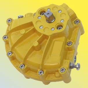
3 Durable epoxy stove enamel finish Long life epoxy or PTFE internal finish Integral vane/shaft casting - only one moving part Manual override square and position indicator Stainless steel expanders ensure long term lipseal / case contact Kinetrol Vane Actuators Easy stop adjustment at each end of stroke for accurate seating Corrosion resistant zinc (nonincendive) or aluminium alloy case Space filling/energy absorbent sideplates (polymer or metal) Double opposed, Polyurethane, lip seals for effective sealing and long maintenance free life Single moving part Simplest and most reliable mechanism for quarter-turn rotary actuation. Close couple control modules Fail-safe spring returns, limit switches, positioners and solenoid valves all close couple to the actuators. No cranks or gearing No power loss or backlash - allows accurate positioning. Durable corrosion resistant finish Long maintenance-free life Up to 4 million operations guaranteed. Compact - space saving - efficient Best torque/size package available, fast operating speeds, best air consumption, proven design. Millions of units in trouble free service all over the world Choice of male or female output drive square - easy to interface to application Unique serial number for identification and traceability Applications Operation or positioning of ball, butterfly and plug valves, ventilation dampers and automatic doors. Uses also include movement and positioning of components during manufacture - in fact anything that needs to be turned through 90 or less, automatically or by remote control. Certificate No. FM22163 For ordering codes see page 62 The policy of KINETROL is one of continuous improvement. We reserve the right to alter the product as described and illustrated without notice. Kinetrol's rigorous quality program is approved to ISO 9001:2008 ensuring that each unit is manufactured to the highest standards. 2

. 4. AP Positioner 3-15psi (0.")
4 Modular Add On Control Units Kinetrol Actuators, Springs and Accessories are approved up to ATEX Category 1. Kinetrol modular concept easily provides the control assembly needed 1. Visual Indicator Gives visual indication of valve position as standard except models 0M0, 01, 16, 18, 20 and Clear Cone Monitor Gives 360 and overhead position indication. Available on actuator models 03, 05, 07, 08, 09, 10, 12, 14, 15, limit switch boxes, AP positioners, EL positioners, P3 positioners and EHD models (details page 20). 3. I/P Controller mA electrical signal controls main air supply to pneumatic positioner as alternative to air signal control (details page 19). 4. AP Positioner 3-15psi (0.2-1 bar) air signal controls main air supply to turn, stop or hold the actuator vane in proportional response to that air signal. Limit switch and angle 5. retransmit options available (details pages 17/18). 5. EL Electropneumatic Positioner A single unit gives smooth accurate control in response to a 4-20mA signal. Limit switch and angle retransmit options in same housing (details pages 15/16). 6. P3 On/Off Positioner Modulation and/or two endstop positions and a mid-range setpoint anywhere within the 90 span. Easy setpoint adjustment and integral position feedback options (details page 21/22). 7. Explosion Proof P3 On/Off Positioner Provides the same basic options as the P3 Positioner 9. but in a flame proof enclosure with ATEX approval (details page 23). 8. Universal Limit Switch Box Weathertight unit with up to 4 switches for remote position indication or control use. Optional switches for flame proof/explosion proof needs and high visibility Clear Cone monitor (details pages 9/10). 9. Explosion Proof Limit Switch Box Provides the same basic options as the Universal Limit Switch Box but in a flame proof enclosure with ATEX, FM and IEC approvals (details page 11/12). 10. Solenoid Optional integral pneumatic solenoid valve for actuators. Various electrical, environmental and explosion proof requirements covered (details page 20). 11. Actuator 16 sizes covering torque range 0.5 Nm (5 lbf in) to Nm (168,000 lbf in). Operating air pressure range 1.4 bar (20 psi) to 7 bar (100 psi). Adjustable stops as standard. Restricted travel stops and ISO/DIN versions available (details pages 29 to 44) Converter Compact units give constant torque output through up to 200 travel (details pages 25/26). 13. Fail-Safe Spring Return Units Clock type spring return gives reliable fail-safe operation with high torque output throughout spring stroke, yet has easy adjustment to suit application (details pages 5 to 7). 14. Spring To Centre Patented spring unit to provide accurate adjustable port travel position on loss of air/signal (details page 24). 15. ISO Adaptor The patented ISO adaptor provides easy conversion from a Kinetrol male drive to an ISO flange interface for ultimate mounting flexibility (details page 8). 16. Gearbox Geared manual override on all models from 05 to 20 excluding model 15 (details page 46). 17. Mounting Bracket A comprehensive range of brackets provides for most ball, plug and butterfly valves (details page 45)
5 XLS MOUNT PLATE KIT SP/ASP /03 SQUARE REDUCER SP/ASP /05 SQUARE REDUCER SP/ASP1602 Models 03 & ULS XLS 05 ULS 05 EL 05 AP 03 ACTUATOR 05 ACTUATOR Models 07 to CLEAR CONE Top-Mount Accessory Build Arrangements (Limit Switch Boxes & Positioners) 07 CLEAR CONE XLS 07 ULS 07 EL XLS MOUNT PLATE KIT SP/ASP AP (FOR 07 TO 09) 07 MP (FOR 10 TO 15) 12,14 & 15 UNIVERSAL ACCESSORY MOUNTING ADAPTOR KITS SP/ASP1608 & SP/ASP ACTUATOR 08 ACTUATOR 09 ACTUATOR WITH 07 SQUARE WITH 07 SQUARE 10 ACTUATOR WITH 07 SQUARE NOTE: MODELS 05 TO 15 STANDARD ACTUATORS ARE FITTED WITH REMOVABLE PLUG SCREWS IN POSITIONER PORTS ALLOWING RETROFITTING OF 05/07 SIZE POSITIONERS 12 ACTUATOR WITH 07 SQUARE 14 ACTUATOR WITH 07 SQUARE 15 ACTUATOR WITH 07 SQUARE Models 16 to 30 XLS 07/05 SQUARE REDUCER SP1602 KINETROL DISCRETE 05 DRIVE SP1601 KINETROL DISCRETE ULS KINETROL DISCRETE EL KINETROL DISCRETE HP KINETROL DISCRETE 05 DRIVE SP1601 (INCLUDED WITH DISCRETE EL) KINETROL DISCRETE 05 DRIVE SP1601 (INCLUDED WITH DISCRETE HP) 16 UNIVERSAL ACCESSORY MOUNTING KIT SP/ASP UNIVERSAL ACCESSORY MOUNTING KIT SP/ASP & 30 UNIVERSAL ACCESSORY MOUNTING KIT SP/ASP ACTUATOR 18 ACTUATOR 20 ACTUATOR 30 ACTUATOR 4

6 Fail-Safe Spring Return Units Lowest Torque Loss Typically 20% through 90 yields extra torque through spring stroke - enables the selection of smaller actuators (see diagram) Reliable low stress range clock type spring Separate housing for modular assembly, easily retrofitted Sealed, non-breathing housing Protects spring in corrosive environments Adjustable pretension for 'balanced' air and spring stroke torques Various combinations available for balanced / optimised torques at various air pressures Keeper plates available to ensure safe handling of pretensioned springs Available with ISO/DIN female drive and mounting for models Spring housing cut away Springs guaranteed against failure for lifetime of actuator ATEX Category 1 approved for many models Category 2 for other models The diagram shows the torque requirement of a typical ball valve under normal conditions. The typical torque output characteristics of Kinetrol and Rack and Pinion actuators, both sized to overcome the valve's breakout torque, are also illustrated. The diagram demonstrates that the Kinetrol actuator will exceed the torque requirement of the valve throughout the entire stroke whilst the rack and pinion unit will fail to reseat the valve. Breakout 100% TORQUE Typical Rack and Pinion Unit Kinetrol Typical Ball Valve 80% 70% 60% Reseat The higher torque losses associated with the rack and pinion actuators (torque loss can be as high as 70%) dictate the selection of larger units to ensure complete reseating. All spring units are guaranteed, in normal use, to operate correctly as long as the original actuators to which they were fitted. 0 STROKE TO OPEN 90 CLOSED OPEN 5

7 Direction of Spring Action Spring units are available for either clockwise or counter clockwise spring action. Spring units are mounted as standard between the actuator and what it drives. With spring units alone, direction is determined by looking at the unit from the end which interfaces with the actuator. Suffix = clockwise Suffix = counter clockwise Pretension Setting Factory assembled actuator/spring return assemblies have the spring pretension set for 'balanced' torque output when the actuator is operated by air at 80psi (5.5bar). Factory assemblies can be preset for different air pressures below 80psi (5.5 bar) on request. Spring return units supplied separate from actuators are also pretensioned for 80psi (5.5 bar) air operation unless otherwise stated. Fail-Safe Spring Return Units The direction of actuator/spring assemblies are determined by looking at whole assembly from the non-output end. Asyetrical Torque Applications If high torque is required in one direction and lower torque in the other direction this can be set up easily by changing spring pretension to be higher or lower as required. Air stroke torque will always be double-acting torque (at air pressures available) less spring pretension torque. Low Air Pressure Applications If air pressure available for actuator operation is less than 50psi (3.5 bar), 'balanced' torque output on air and spring strokes is still possible by using a spring return unit from a smaller actuator size. Listed below are factory assembled options of this kind. Replace the '*' used in ordering codes below with a '2' (clockwise) or '3' (counter clockwise) depending on direction of spring action required. Keeper Plates These are provided on all pretensioned spring return units supplied separate from actuators. They are also available as spare parts. Refer to TD121 for part numbers. A keeper plate must always be used to restrain spring tension whenever a spring unit case is removed from the actuator. Materials Specifications Spring Casing Models 02 to 05 pressure die-cast in ZL 16 zinc alloy. Models 07 to 30 in aluminium alloy. Finish Epoxy stove enamel. Spring Clock type spring steel. Square Steel, zinc plated. Mount Holes (output end) Same as matching actuator (except model 01), low pressure combinations & ISO drive versions. See page 51/52 & TD121. See pages 59 & 60 for full torque details and pages 51 & 52 for dimensions of all models. Refer to TD121 for available male and female drive low pressure spring options. Ordering Code Description 03-1* actuator with one 02 spring unit 07-1* actuator with one 05 spring unit 09-1* actuator with one 07 spring unit 10-1* actuator with one 09 spring unit 12-1* actuator with one 09 spring unit 12-1* actuator with two 09 spring units 14-1* actuator with two 12 spring units 14-1* actuator with one 12 spring unit 16-1* actuator with one 14 spring unit and one 12 spring unit 16-1* actuator with one 14 spring unit 18-1* actuator with one 16 spring unit 20-1* actuator with two 16 spring units 20-1* actuator with three 16 spring units 30-1* actuator with three 16 spring units 30-1* actuator with four 16 spring units 30-1* actuator with five 16 spring units 6

 Torques are identical to standard and low pressure spring torques given on pages 59 & 60. Directions of spring action are as described on page 6.")

8 Female Drive Spring Units Simple, elegant direct-mount interface for most valves Multiple ISO mounting flange hole drillings for each model Large ISO/DIN compatible star drive for most models Valve leak tell-tale/relief slots in mounting face Female serrated insert drive options available for maximum direct mount flexibility on some models Keeper plates available to ensure safe handling Same reliable, long-life, fully sealed spring unit as on male-drive units Allows accessories to be direct mounted to top of actuator (e.g positioner) Torques are identical to standard and low pressure spring torques given on pages 59 & 60. Directions of spring action are as described on page 6. Female drive spring units are always designed to be mounted between the actuator and the application. Consequently, a female spring designated clockwise as a separate module will, when mounted below an actuator, result in a clockwise assembly. Female drive springs are not designed to interface directly with modular switch boxes, positioners etc. ISO/DIN Star Drives Female bi-square (star) drive spring fail-safe units are available for models 03 to 20. Star drive units are specified by adding a F to the DIN/ISO code: e.g. for a standard model 07 actuator with a female star drive, a regular code becomes 073F120. See page 52 for full dimensions. Serrated Drives Female serrated drive spring fail-safe units are available for models 05, 07, 08, 09 & 10 to give maximum mounting flexibility. Features include: - Can accoodate large diameter valve stems - Deep hole in shaft for long valve stems - Precision stainless steel inserts - Coon internal drive shapes available - Same spring can be used with different valve type/sizes - 48 teeth allow many different orientations Serrated drive units are (excluding couplings) specified by adding an S to the ISO/DIN code: e.g. for a standard model 07 actuator with a serrated female drive, a regular code becomes 073S120. See TD141 for full dimensions of the serrated drive springs and associated couplings. A range of blank and internally profiled serrated stainless steel couplings are available (see TD141 for codes). Coding of Alternative Flange Drillings Some female spring fail-safe star and serrated drive models are available with alternative ISO mounting hole patterns (see page 52 and TD141). The digits 8 and 9 are used to designate clockwise and anti-clockwise versions respectively: e.g. clockwise code 053F180 specifies the F04 flange alternative of the 053F120 which specifies the clockwise F03/05/07 version. 7

9 Ultimate Mounting Flexibility Low cost direct mount flange and coupling for mounting to valves with ISO 5211 drive interfaces, available for actuator models 02, 03, 05, 07, 08 and 09 Mounting directly to standard Kinetrol double acting actuator thereby reducing stocking requirements Multiple mounting hole sets in one part ISO Adaptor International patents. The novel design allows metric mounting screws to face in either direction. Valve flanges with tapped holes can easily be interfaced for the first time. Nut recesses in flange make for easy installation Robust epoxy coated zinc alloy adaptor with no threads for maximum corrosion resistance Female drive bi-square (star) coupling is retained by adaptor and made from zinc plated steel (other materials available on request) Serrated drive versions also available. H HEXAGON RECESSES X International Patents FEMALE BI-SQUARE G x E DEEP (COUPLING RETAINED) W Y VENT GROOVES FIXED J Adaptor Kit* Order Codes ISO Flange Sizes H J G E * ANSI (e.g. ASP1449) colour versions (identical dimensions) also available. ** Default 03 version Minimum Also mounts directly to male drive spring units W PCD X PCD Y PCD Weight Kg SP F120 / 023F100 F03/F F180 / ( Z SP 1407 fitted with SP1407) F SP F100** F03/F SP Z fitted with SP1454 F SP F100 F04/F05/F SP F100 F05/F SP F100 F07/F SP F100 F07/F


10 Universal Limit Switch Box Offers a wide range of signalling options in a fully enclosed corrosion resistant case. Available for direct mounting onto Kinetrol rotary actuators, or discrete mounting via an industry standard VDI/VDE interface onto any make of rotary actuator. Easy to wire and set up with real industrial quality robustness. Internally fitted options include AS Interface digital counication and a 4-20mA 2-wire modulating angle retransmit circuit. The range of switch and terminal arrangements includes 2 or 4 switches, extra connections allowing single point termination of wiring for limit switches and solenoid valves, ATEX approved Eexed (Category 2) explosion proof and Eexia intrinsically safe packages (Category 1). Integral sealed Clear Cone Monitor and red/green Led indicator options also give excellent external visual indication of position. See KF-487 for full details. Specification Casing Precision diecast aluminium alloy, switch option 003 Eex ed diecast zinc alloy Finish Epoxy stove enamel Seals Nitrile rubber O ring seals Weight 0.7 kg Switch option kg Cable entry options 2 or 4 entries M20 x 1.5 Conduit thread or 1 /2 NPS Conduit thread 4 Way plug DIN 43650A (fits any conduit thread) 4 Way M12 Connector (M20 Conduit thread only) Temperature Range Standard -20 C to +80 C High Temp Seals up to 100 C Also see switch temperatures on page 10 Dimensions See page 53 All units sealed to IP66/NEMA 4X. IP67 option available Robust corrosion resistant epoxy painted diecast box Easy and accurate setting of switch position Available for direct mounting to Kinetrol models 03 to 15, for minimum height Quick access - No special tools required Discrete VDI/VDE (NAMUR) interface option for use with industry standard actuators Two or four cable entries as standard to allow back wiring of solenoid valves Many switch options available for general and hazardous areas AS Interface bus circuit option inside box reads up to 4 switch inputs, drives up to 2 solenoids powered by bus only (see pages 13 & 14) Optional Clear Cone monitor available Integral LED indicator lamps and angle retransmit circuit options are available Compact SPST version of type 004 available for model 02 actuator LOAD RATINGS FOR STANDARD MICROSWITCHES (type 004) Voltage 125 V AC 15A 250 V AC 15A up to 12 V DC up to 24 V DC up to 48 V DC Resistive Load 15A 10A 3A up to 250 V DC 0.25A MULTIPLICATION FACTORS FOR NON-RESISTIVE LOADS Steady state tungsten lamp load - x 0.1 Steady state inductive load - x 0.2 Peak inductive load - x 1.0 9
11 Ordering Codes Switch Type intrinsically safe 2 wire inductive proximity sensors for hazardous areas (ATEX CAT 1), normally closed. Ambient temperature range -20 C to +80 C Switch Type pneumatic switches with 4 (5.32 ) push in fittings (ATEX CAT 2), normally closed. Ambient temperature range -20 C to +80 C Switch Type 003 Certificated unit to EEx ed II T6 for hazardous areas to Zone 1 (ATEX CAT 2) 2 x 3 wire switches for SPDT. Ambient temperature range -20 C to +70 C Switch Type x 3 wire microswitches for SPDT. Ambient temperature range -40 C to +80 C Switch Type x 2 wire proximity sensors volts AC, normally open. Ambient temperature range -25 C to +70 C Switch Type x 2 wire proximity sensors 5-60 volts DC, normally open, with Led switch status indicators. Ambient temperature range -20 C to +80 C Switch Type x 3 wire microswitches for DPDT. Ambient temperature range -40 C to +80 C Switch Type x 2 wire inductive slotted proximity sensors, normally closed. Ambient temperature range -20 C to +80 C Switch Type x 3 wire gold plated contacts intrinsically safe microswitches for SPDT (ATEX CAT 1). Ambient temperature range -20 C to +80 C Switch Type 00E 2 x 2 wire proximity sensors volts AC / volts DC. Ambient temperature range -25 C to +80 C Switch Type 00N 2 x 3 wire inductive proximity sensors volts DC, normally open. Ambient temperature range -25 C to +70 C Electronics Option B - E AS interface options are available with both the two and four entry Kinetrol Universal Limit Switch Box. Options B to E allow for different extended addressing options. For more information on the Kinetrol AS interface card see page 13 & 14. Electronics Option P Two or four way Universal Limit Switch Box fitted with potentiometer (20K ohms conductive plastic type). Electronics Option R Two or four entry Universal Limit Switch Box fitted with angle retransmit, loop powered two wire circuit passes 4-20mA current, proportional to 0-90 position of actuator. Electronics Option U (standard) Two or four entry Universal Limit Switch Box without AS interface card, angle retransmit or potentiometer. Universal Limit Switch Box SWITCH TYPE 0=CONTACT KINETROL FOR DETAILS 1=2x V3 i-safe PROXIMITY SENSORS ATEX 2=2x PNEUMATIC SWITCHES ATEX 3=2x SWITCHES EExe II T6 CERTIFIED ATEX 4=2x V3 SPDT SWITCHES 5=2x Vac PROX. SENSORS 6=2x 5-60Vdc PROX.SENSORS 7=4x V3 DPDT SWITCHES 8=2x SLOTTED PROX SENSORS 9=2x V3 SPDT i-safe (GOLD PLATED) ATEX A=4x CODE 1 SENSORS 7.530Vdc B=4x CODE 5 SENSORS C=4x CODE 6 SENSORS D=4x CODE 9 SWITCHES E=2x V Vac / Vdc INDUCTIVE SENSORS F=4x CODE E SENSORS N=2x 10-30Vdc PNP 3 WIRE PROX. SENSORS RH LH ACTUATOR MODEL NOT AVAILABLE ON ATEX VERSIONS 4=M20 (ISO) 7=1/2" NPS ELECTRONICS OPTION B=WITH ASi BUS (See KF-496) C=ASi EXTENDED ADDRESSING, OUTPUTS DISABLED D=ASi EXTENDED ADDRESSING, OUTPUTS ENABLED E=ASi EXTENDED ADDRESSING, OUTPUTS ENABLED, SEPARATE POWER SUPPLY U=WITHOUT ELECTRONICS R=WITH ANGLE RETRANSMIT P=WITH POTENTIOMETER 0=NO ACTUATOR 1=ACTUATOR SPRING OPTIONS 0=NO SPRING 2=CW SPRING 3=ACW SPRING B C D E U R P 0 0= NO ANGLE RETRANSMIT 1= ANGLE RETRANSMIT CW 2= ANGLE RETRANSMIT ACW 0=DIRECT MOUNT UNIT 1=DISCRETE UNIT WITH KINETROL SQUARE 2=DISCRETE UNIT WITH NAMUR INTERFACE 3=DISCRETE UNIT WITH KINETROL SQ.+HI TEMP SEALS 4=DISCRETE UNIT WITH NAMUR INTERFACE+HI TEMP SEALS 5=DIRECT MOUNT BOX+HI TEMP SEALS 0= 2X3 CONNECTION TERMINAL BLOCKS 4= 3X3 CONNECTION TERMINAL BLOCKS 5= 4X3 CONNECTION TERMINAL BLOCKS 6= MULTI-TERMINAL PCB (5x3 + 1x2) M=CLEAR CONE MONITOR - STANDARD R=CLEAR CONE MONITOR - EXTRA CHEMICAL RESISTANCE A=CLEAR CONE MONITOR - ATEX (SWITCH OPTION 1 & 9 ONLY) 0=NO LED FITTED 1=2 LED'S RED + GREEN 240 / 110 V ac 2=2 LED'S RED + GREEN 12 / 24 V dc 3=2 LED'S RED + GREEN WITH ASi BUS 0=PNEUMATIC SWITCH CONNECTION 1=2 ENTRIES - 2 TRANSIT PLUGS 2=2 ENTRIES - 1 TRANSIT, 1 BLANKED (R.H.) 3=2 ENTRIES - DIN PLUGS 4=2 ENTRIES - DIN PLUG, 1 BLANKED (R.H.) 5=4 ENTRIES - 4 TRANSIT PLUGS 6=4 ENTRIES - 3 TRANSIT, 1 BLANKED (R.H.) 7=4 ENTRIES - 4 DIN PLUGS 8=4 ENTRIES - 3 DIN PLUGS, 1 BLANKED (L.H.) 9=4 ENTRIES - 2 DIN PLUGS, 1 BLANKED (L.H.), 1 TRANSIT For more information see KF-487 PLUG OPTIONS FOR AS INTERFACE A=M12 PLUG FOR AS INTERFACE & TRANSIT (RH) EXAMPLES: B=M12 PLUG, M12 SOCKET WITH ASI CABLE CLAMP & TRANSIT (RH) U = 05 ULS BOX WITH 2 X V3 i-safe PROXIMTY SENSORS, 2 TRANSIT PLUGS & 2 X 3 WAY TERMINALS ATEX APPROVED C=M12 PLUG FOR AS INTERFACE & BLANK (RH) R = 05 ULS BOX WITH 2 X V3 i-safe PROXIMTY SENSORS, 2 TRANSIT PLUGS & 2 X 3 WAY TERMINALS, AR CW NOT APPROVED D=M12 PLUG, M12 SOCKET WITH ASI CABLE CLAMP & BLANK (RH) R = 07 ULS BOX WITH 2 X V3 SPDT SWITCHES + 1 TRANSIT & 1 BLANKING PLUG & ANGLE RETRANSMIT ACW NOT APPROVED U = 07 ULS BOX WITH 2 X V3 SPDT SWITCHES + 2 TRANSIT PLUGS + LED'S RED / GREEN 12 / 24 V dc NOT APPROVED Unless otherwise specified M12 plug will always be connected on the left side port C = 07 ULS BOX WITH 2 X V3 i-safe MECH.SWITCHES G / PLATED, ASi WITH EXTENDED ADDRESSING OUTPUTS DISABLED + 2 TRANSIT PLUGS NOT APPROVED B00A00M = 09 SPRING RETURN ACTUATOR & ULS BOX WITH 2 X V3 SPDT SWITCHES + STANDARD ASi & ASi TERMINALS + M12 PLUG +TRANSIT PLUG + CLEAR CONE MONITOR NOT APPROVED B = 07 ULS BOX WITH 2 X V3 i-safe MECH.SWITCHES G / PLATED, STANDARD ASi + 2 TRANSIT PLUGS & ASi TERMINALS + 2 LED S RED & GREEN NOT APPROVED Further switch options are available upon request - contact Kinetrol for details 10


 - all in one device All units protected to IP66 / NEMA 4X / TYPE 4X Attractive, functional and")
12 Explosion Proof Limit Switch Box The Explosion Proof Limit Switch Box offers a wide range of signalling options in a compact corrosion resistant aluminium alloy housing. Available for close - mounting onto Kinetrol actuators or discrete mounting via a Kinetrol 05 square or industry standard VDI/VDE interface onto any make of rotary actuator. Easy to wire and set up with true industrial robustness. Internally fitted options include AS interface digital counication and a 4-20mA, 2-wire, modulating angle retransmit circuit. The range of switches and terminal arrangements includes 2 or 4 switches and extra connections - allowing single point termination of wiring for limit switches and solenoid valves. This product is available to mount on Kinetrol models Wide range of worldwide explosion proof approvals including IECEX, ATEX & FM (for USA & Canada) - all in one device All units protected to IP66 / NEMA 4X / TYPE 4X Attractive, functional and part-spherical profile. Robust corrosion resistant, Anodised & epoxy painted diecast aluminium alloy housing Close - mount to Kinetrol actuator models for low profile Discrete Kinetrol 05 square drive insert for use with Kinetrol actuator models Discrete NAMUR drive for use with VDI/VDE 3845 drive actuators 2 or 4 cable entries available to allow back wiring of solenoid valves Up to 4 switches available for SPDT, DPDT or multiple circuit operation Easy and accurate setting of switching position Optional antistatic Clear Cone Monitor available Integral angle retransmit circuit options are available Integral AS interface bus circuit option reads up to 4 switch inputs and drives up to 2 bus powered solenoids -40 C to +80 C ambient operating temperatures (dependent on switch options) Positioner options available 11


13 Switch Code Switching Operation Conditions Voltage AC DC Current Labels IECEx & ATEX - Approval type E Temperature Range 1/A 8 6mA -20 C to +80 C 4/ A AC/1.8A DC -40 C to +80 C 5/B mA -25 C to +70 C 6/C mA -20 C to +80 C 9/D mA -40 C to +80 C E/F mA -25 C to +80 C N mA -25 C to +70 C Specification NORTH AMERICAN APPROVAL Type of US: Class I, Division 1, Gas groups protection, B,C,D. Class II, Division 1, Dust groups Explosion E,F,G. T5 NEMA 4X. Proof For Gas group A use order code P. CANADA: Class I, Division 1, Gas groups B,C,D. Class II, Division 1, Dust groups E,F,G. T5 TYPE 4X. EUROPE/GLOBAL - ATEX / IECEx APPROVAL Protection Group II C/A21, Category 2, Gas & concept, Dust, T5, IP66 Flame Proof d Casing precision diecast LM24 alloy, anodised & epoxy stove enamel. Explosion Proof Limit Switch Box FMC/U, IECEx & ATEX - Approval type F & P Coupling Seals Weight Cable Entry Options zinc plated steel. fluoropolymer dynamic seals and NBR static seals. 1.5 kg M20 x 1.5 or 1/2 14 NPT conduit entry threads. Dimensions see page 53 Ordering Codes 0 = WITHOUT ACT 1 = WITH ACT APPROVAL TYPE E = IEC / ATEX IIC, IIB, IIA F = FM / FMC GRPS B,C,D P = FM GRP A SWITCH OPTIONS (SUPPLIED WITH 2 STRIKERS AS STANDARD) 1 = 2 x V Vdc, NC, 2 WIRE INDUCTIVE SENSORS 4 = 2 x V3 SPDT, 0-250Vac, MECHANICAL MICROSWITCHES 5 = 2 x V Vac / Vdc NO, 2 WIRE, INDUCTIVE SENSORS 6 = 2 x V3 5-60Vdc, NO, 2 WIRE, INDUCTIVE SENSORS 7 = 4 x CODE 4 MICROSWITCHES 9 = 2 x V3 SPDT, 0-250Vac, GOLD PLATED CONTACTS MECHANICAL MICROSWITCHES A = 4 x CODE 1 SENSORS B = 4 x CODE 5 SENSORS C = 4 x CODE 6 SENSORS D = 4 x CODE 9 MICROSWITCHES E = 2 x V Vac / Vdc, NO, 2 WIRE, INDUCTIVE SENSORS F = 4 x CODE E SENSORS N = 2 x 10-30Vdc, PNP, 3 WIRE, PROXIMITY SENSORS = MALE F = FEMALE S = SERRATED 0 = NO SR 2 = SR CW 3 = SR CCW X B = 2 ENTRY D = 4 ENTRY 0 0 = 2 x 3 TERMINALS 4 = 3 x 3 TERMINALS 5 = 4 x 3 TERMINALS 6 = MULTI-TERMINAL PCB (2x6 + 1x3 + 1x2) 0 = STANDARD INDICATOR A = ANTI-STATIC MONITOR 0 = CLOSE-MOUNT (03-14 MODEL-SPECIFIC) 1 = DISCRETE KINETROL 05 SQUARE DRIVE (16-30 MODEL-SPECIFIC) 2 = DISCRETE NAMUR 3 = NO MOUNTING PARTS (NON MODEL-SPECIFIC) NOTE: ACTUATORS REQUIRE DISCRETE MOUNTING MOUNTING PARTS AVAILABLE: SP SQUARE DRIVE SP /05 SQUARE REDUCER SP NAMUR DRIVE SP /03 SQUARE REDUCER SP/ASP CLOSE MOUNTING KIT SP/ASP /14/15 ACCESSORY MOUNTING ADAPTOR (UNDRILLED) SP/ASP389 - MODEL 16 MOUNT KIT SP/ASP329 - MODEL 18 MOUNT KIT SP/ASP400 - MODEL 20/30 MOUNT KIT TERMINALS NEEDED FOR OPTIONS NO BACKWIRING ASI + 2 OR 4 SWITCHES = 2x3 (0) A/R + 2 SWITCHES = 2x3 (0) A/R + 4 SWITCHES = PCB (6) POT + 2 OR 4 SWITCHES = PCB (6) 2 SWITCHES = 2x3 (0) 4 SWITCHES = 4x3 (5) WITH BACKWIRING A/R + 2 SWITCHES = PCB (6) A/R + 4 SWITCHES = PCB (6) POT + 2 SWITCHES = PCB (6) POT + 4 SWITCHES = PCB (6) SEE NOTE 2 SWITCHES = 3x3 (4) 4 SWITCHES = PCB (6) For more information see KF-619 ACTUATOR MODEL = DIN FLANGE STANDARD (FEMALE DRIVE) NOT AVAILABLE WITH 4 = ISO (M20) THREAD APPROVAL TYPES A = DIN FLANGE STANDARD WITH NAMUR ADAPTOR F & P B = ISO (M20) THREAD STANDARD WITH NAMUR ADAPTOR C = ANSI (1/2" NPT) THREAD STANDARD WITH NAMUR ADAPTOR 7 = ANSI THREAD (1/2" NPT) NOTE - POT + 4 SWITCHES WITH BACKWIRING WILL NOT HAVE ENOUGH TERMINAL CONNECTORS TO WIRE ALL NORMALLY OPEN / NORMALLY CLOSED SWITCH CONNECTIONS WITH 3 POT CONNECTIONS. 0 = NO OPTIONS B = ASi BUS C = ASi EXTENDED ADDESSING OUTPUTS DISABLED D = ASi EXTENDED ADDRESSING OUTPUTS ENABLED E = ASi EXTENDED ADDRESSING OUTPUTS ENABLED, SEPARATE POWER SUPPLY F = ANGLE RETRANSMIT CLOCKWISE G = ANGLE RETRANSMIT ANTI-CLOCKWISE P = POTENTIOMETER 12


14 AS Interface Bus Counications The Kinetrol AS Interface Card The Kinetrol AS Interface card is fitted inside the Kinetrol Universal Limit Switch box, thus combining the industrial quality robustness of the box with the advantages of digital serial counication. The AS interface bus cable can be routed in through the conduit entries and connected to the internal terminal blocks. Alternatively, an M12 connector plug facing outwards from the conduit entry can be supplied to allow quick connection from M12 sockets or with clip on adaptations for ribbon type yellow AS interface cables. AS Interface Card Features 13 AS Interface Bus The Actuator Sensor Interface card allows easy digital serial counication for your sensors and actuators, allowing your actuators to be controlled and monitored when they are in the field, via a single 2 wire cable. AS interface devices are used to make up control systems based on a two-wire counication cable known as a bus. These can be controlled or monitored by means of a digital signal sent via the bus to and from a "master" device (which can be a computer or a PLC). The slave devices will always function in response to coands sent by the master device, either to actuate or to return a message reporting the value of a sensed variable, or both. The AS Interface specification allows 31 or fewer slave devices to be powered by a DC voltage fed into the same two wire cable used as the counication bus, with allowed power consumption adequate to drive the slave plus a standard pneumatic solenoid valve. An AS Interface bus can be used as the final field link in a more complex hierarchy of devices making up a large plant-wide control system. Actuators and sensors must often be installed in unprotected environments where conditions can be demanding; the AS Interface bus can be used as the link between these field devices and the "indoor" equipment making up the upper part of the control system. The AS Interface bus is designed for on/off control and monitoring. It is a good choice when a simple, economical, reliable and robust solution is required for controlling and monitoring a series of actuators and sensors in a process control or machine application. AS interface 2.1 compatibility Up to 31 units with solenoid valve on-off control, powered and controlled via a single, two core cable Up to 62 units (using extended addressing) All metal robust industrial-quality limit switch box, direct mounted on a Kinetrol actuator 2 on/off outputs per unit 4 on/off inputs per unit Reads mechanical switches or inductive sensors Retrofittable to standard Kinetrol Universal Limit Switch Box Can also be supplied in an explosion proof housing and with European, North American and Worldwide approvals LED external indicator option Up to 31 24V 2.5W solenoid valves can be connected to bus with no separate power supply M12 connector plug option available for instant bus connection Cable clamping connector block for yellow ribbon-type AS interface cable available with M12 socket to fit onto plug option Output short circuit protection built in Operating temperature range -20 C to +80 C (-40 C option available - contact Kinetrol)
15 AS Interface Configurations AS Interface 2.1 Specification Master - Slave protocol Up to 31 Slaves per Master Each Slave has its own unique address (set by user) All Slaves can be scanned every 5 milliseconds Baud Rate Kbits/second Slaves may be added anywhere in the bus AS Interface Bus Counications Slaves may be parallel connected on the bus, using star or spur configurations Up to 124 inputs per bus Up to 124 outputs per bus, 62 using the Kinetrol device 26.5 to 31.5 Vdc, 8 A max power supply 100 m (325ft) maximum cable length (repeaters may extend network distance) AS Interface Extended Addressing Untwisted, unshielded, 2-wire (1.5 2 ) cable can be used Kinetrol's AS Interface circuit is a slave device to allow 32 devices (usually 31 slaves plus an AS Interface master device) to be powered and controlled via a 2-wire bus cable, with full capability to energise one solenoid on every unit all at the same time. This is the standard (Option code B). The AS Interface 2.1 specification also allows for an extended address option, whereby 62 addresses can be connected and powered via one bus cable. The specified limits on device capacitance however, mean that if the full extended-address compliment of slaves all had standard solenoid valves connected, the bus limit would be exceeded. Kinetrol offer these options to allow use of extended addressing: 1. (Option Code C) AS Interface circuit with extended addressing enabled and outputs disabled, to read limit switch sensors only. If a solenoid is connected it will not function. 2. (Option Code D) AS Interface circuit with extended addressing and outputs enabled (one solenoid per interface card), plus added isolating relay option fitted to outputs, to allow up to 31 solenoids to be energised simultaneously even from the bus, though up to 60 slave units may be connected to the bus. This requires the user's control system to include a pre-prograed limit on the maximum number of solenoids to be energised. If the system instructs too many units to switch on solenoids, they will obey, and the bus capacitance limit will be exceeded thus this option must be at the user s risk with regard to this issue. For more information see KF (Option Code E) AS Interface circuit with extended addressing and outputs enabled (one solenoid per interface card), plus added relay options fitted to outputs to allow solenoid valves to be powered by a supply separate from the AS Interface bus. This option requires a separate 24V DC power supply to each actuator, and allows up to 60 slave units to energise their solenoids simultaneously. To order the Kinetrol AS Interface card refer to codes for Universal Limit Switch Box or Explosion Proof Limit Switch Box on pages 10 and

16 EL Electropneumatic Positioner Operation The EL positioner uses a unique low power proportional servo valve to control the position of a quarter-turn actuator. The microprocessor in the loop-powered 4-20mA position circuit reads the signal via one channel of a 12-bit A-D converter, reads the position voltage from the feedback potentiometer via the second channel of the A-D converter, and compares the two. If it detects a position which is different from that required by the signal, it changes the output to the servo valve, in order to drive the actuator in the direction required to reach the correct position. As the actuator moves, the feedback potentiometer voltage changes and the microprocessor continually calculates the adjustments required for the servo valve in order to guide the actuator accurately into position. The microprocessor is prograed with a sophisticated but compact algorithm which allows this critical dynamic valve adjustment to be made correctly. This in turn gives optimal results with any actuator/load combination - slow or fast, low or high friction, low or high inertia. All can be optimised by tuning the PGAIN and DAMP push buttons via the positioner circuit push buttons. The EL positioner controls airflow to an actuator and moves it to a position determined by a 4-20mA signal. It s features are: Fast, smooth and precise control from a digital circuit and proportional servo valve Simple time saving field set up Quick calibration via push buttons and LED feedback and easy reversal of rotation sense (clockwise/counter clockwise) without special tools or parts change. Universal application The unit can be mounted in any orientation on to any quarter turn or linear application by connection via a NAMUR or Kinetrol square interface. Loop powered No separate power needed, just a 4-20mA signal plus air supply. Integral options - easily retrofitted modules include: - two wire 4-20mA isolated angle retransmit - mechanical or inductive position indicator switches (general or hazardous areas) - Clear Cone high visibility indicator - Threaded conduit entries or DIN plugs for external connection. Intrinsically safe approved options Weatherproof, compact and robust metal housing Zero backlash coupling with easily adjustable switch strikers Vibration and shock resistant to 4G Built in gauge ports/external connections 15 Simplified Functional Diagram of EL Positioner
17 Application The EL positioner can be directly mounted on standard Kinetrol actuator models 05 to 15, both double acting and spring return, giving an assembly with no external plumbing, wiring or mechanical connections and the best backlash free control. Mount kits are available for models 16,18, 20 and 30 actuators. Alternatively, discrete versions mount on any actuator via VDI/VDE 3845 NAMUR drive, or Kinetrol male square, with mounting bracket. Special adaptations for linear cylinders are also available - consult Kinetrol for details. The EL Positioner ATEX approval includes the fitting of a special version of the popular Clear Cone high visibility monitor. Air Supply Signal Control Response Sensitivity Specification instrument quality (dry, clean, oil free Class ISO ), 3.5 to 7 bar (50 psi to 100 psi). Consult Kinetrol for 5µm inlet air filter option 4-20mA, requiring max 8V to drive through positioner circuit 0-90 positioning with one linear and 10 non -linear preselected characteristics as standard. Consult Kinetrol for the following versions: i) linearisation of butterfly valve characteristics ii) Pre -selected travel time extension option (with active feedback control of travel speed) iii) customised responses better than 0.1mA* EL Electropneumatic Positioner Hysteresis better than 0.7% of span* Travel Times Direct mount from EL positioner to actuator (zero load) Model Deg/Sec Repeatability Deviation from Linearity Flowrate Operating Temperature better than 0.7% of span* less than 0.7% of span* 3.3 scfm/ bar -20 to +70 C Externally piped from EL positioner to actuator (zero load) Model Deg/Sec Adjustments Weight low & high points (define range), proportional gain, velocity proportional setpoint advance (damping) 2.95 kg/6.5 lb Dimensions see page 55 Ordering Codes Materials Finish case and cover - zinc alloy spool and liner - stainless steel epoxy stove enamel Actuator Assembly Examples: EL000N = discrete ccw ELwith NAMUR drive Enclosure Rating IP65/NEMA 4X Actuator Model = No actuator 4= Act + EL ccw 7= Act + EL cw EL0000M = ccw EL on 054 actuator + LS + Clear Cone Counter clockwise on rising signal is determined looking down on positioner E L 0 M * These refer to the combination of Kinetrol actuator with EL positioner - not just the positioner performance Clear Cone Monitor (Optional) For more information see KF -372 Spring Return or Discrete 0=No SR 2=SR cw 3=SR ccw 4=Pos only ccw 7=Pos only cw Limit Switch 0= No LS 1= 2 x IS prox ATEX Cat 1 4= 2 x V3 mech LS ATEX Cat 1 6= 2 x 5-60 V dc prox* 1 N= 2 x V dc prox* 1 Angle Retransmit / ATEX Approved 0= None 1= Isolated AR 2= IS ATEX 5= IS ATEX with AR DIN plug 0= Conduit Entry C= DIN Plug(s)* 1 * 1NOT AVAILABLE ON IS VERSIONS NAMUR (Discrete Only) 0= Kinetrol N= NAMUR 16

18 AP Positioner The AP positioner moves an actuator to a position set by a 3-15psi control signal and holds it there. Its features are: Fast, smooth, accurate response Simple, all-mechanical function for unbeatable reliability Three flow options to optimise control on all actuator sizes Universal application The unit can be mounted in any orientation on to any quarter-turn or linear application The AP Positioner is designed to drive a rotary or linear actuator to a position set by a 3-15 psi (0.2 to 1.0 bar) signal and hold it there until the signal changes. When a signal pressure is applied to the diaphragm it moves the force balance lever clockwise against the tension of the feedback spring. This moves the spool valve, supplying air pressure to one side of the actuator while exhausting trapped air from the other side. The feedback shaft follows the movement of the actuator and turns the cam counter clockwise, pushing the cam follower and increasing the tension on the feedback spring until it balances the forces on the diaphragm and moves the spool valve to its hold position. The input signal and desired position is determined by the cam profile. A cam giving 0-90 output movement linearly proportional to a 3-15 psi ( bar) signal is standard, and almost any desired characteristic can be supplied to order; if it cannot be found in the list of existing options contact Kinetrol. Schematic Functional Diagram Flexible Diaphragm Operation Feedback Cam Spool Valve Exhaust Supply 90 Motion Feedback Shaft Feedback Linkage Easy set up Quick calibration and reversal of rotational sense (clockwise and counter clockwise) without special tools or parts change ATEX CAT 1 / IECEX approved versions available Easily retrofitted integral module options include: Two wire 4-20mA angle retransmit (inside the same case) Mechanical or inductive limit switches (general or hazardous areas) 4-20mA I/P convertors (general or hazardous areas) Clear Cone visual position indicator (general or hazardous areas) DIN plug option for retransmit connection Low (-40 C) and high (100 C) temperature versions available Fail hold options available Choice of mount options - see opposite Weatherproof, compact and robust metal housing Vibration and shock resistant to 4G Signal Pressure 3-15psi To Actuator Built in ports for signal air supply and gauge connections 17 Force Balance Lever Range Adjuster Feedback Spring Zero Adjuster ATEX CAT 2 Exd switch option available
19 The AP positioner can be directly mounted on standard Kinetrol models 05, 07, 08, 09, 10, 12, 14 and 15 actuators, both double acting and spring return, giving an assembly with no external plumbing, wiring or mechanical connections and the best in direct backlash free control. Mount kits are available for models 16, 18, 20 and 30. Alternatively, discrete versions mount on any actuator using VDI/VDE 3845 NAMUR drive, or Kinetrol male square with mounting brackets. Neat adaptations for linear cylinders are also available - consult Kinetrol for details. Air Supply Signal Control Response Sensitivity Hysteresis Deviation from linearity 5.5 bar Operating Temperature Range Weight instrument quality (dry, clean, oil free) 3.5 to 7 bar, (50 psi to 100 psi) standard. Consult Kinetrol for low pressure application 3-15psi ( bar) standard. Consult Kinetrol for split range, 6-30 psi etc linear output standard. Consult Kinetrol for other characteristic cam options better than 0.7% of span* better than 0.7% of span* less than 1% of span* AP: 3.3 scfm (93nl/min) MP: 10.0 scfm (283nl/min) HP: 27.0 scfm (764nl/min) -20 to +80 C Standard -20 to +100 C High Temp -40 to +80 C Low Temp 2.8 kg/6.2 lb Materials case and cover - zinc alloy spool and liner - stainless steel diaphragm: - reinforced polyurethane (standard) - fluorocarbon rubber (high temp) - silicone rubber (low temp) feedback spring - steel Dimensions see page 54 Finish Enclosure Rating Output Torque Specification epoxy stove enamel IP54 same as double acting or spring return actuator. When controlling fast movement of inertia loads consult Kinetrol * These refer to the combination of Kinetrol actuator with AP positioner - not just the positioner performance Maximum Vibration Tolerance Travel Times Maximum velocity (no load) at 80psi 5.5 bar *Externally piped Cam Options Giving typical control characteristics. Contact Kinetrol for details of other options or see TD112. Ordering Codes 4G, 100Hz I/P Converter Options see page 19 Model * Deg/Sec Model 14 14* 15 15* 16* 18* 20* Deg/Sec Input Control Electrical Air Signal Signal 3-15 psi bar 3-9psi bar 6-12 psi bar 9-15psi bar 3-15 psi bar 3-15 psi bar 3-15 psi bar 3-9 psi bar 9-15 psi bar 3-12 psi bar 9-15 psi bar Actuator Model Output Movement Characteristic Cam No. 4-20mA 0-90 Linear 5-1A 4-12mA 0-90 Linear 5-2A 8-16mA 0-90 Linear 5-3A 12-20mA 0-90 Linear 5-4A 4-20mA 0-60 Linear 5-5A 4-20mA 0-45 Linear 5-6A 4-20mA mA mA 0-90 Proportional Flow Proportional Flow Proportional Flow 5-7A 5-8A 5-22A 4-16mA 0-90 Linear 5-13A 12-20mA 0-60 Linear 5-14A pp X=XBox Mount * * * * * * S G * * * Silicone Silicone C=Clear Cone Monitor A=Clear Cone Monitor - ATEX * Not available with ATEX approval For more information see KF-391 AP Positioner 18
 80 psi/5.5 bar nominal G 1 / 8 (fitted with 6 pipe dia. push in connector 1.")

20 I/P Controller Specification - Safe Area Electrical Control Signal Coil Impedance Cable Entry Air Supply Air Entry Weight 4-20mA 20 ohms typical 16 conduit or gland (mini DIN plug, IP 65 with Pg9 cable gland, 6-8 dia optional) 80 psi/5.5 bar nominal G 1 / 8 (fitted with 6 pipe dia. push in connector 1.2 kg The optional Kinetrol I/P Controller is mounted in place of the standard diaphragm housing on the side of the positioner case. The positioner can still be mounted in any orientation and gives an angular output position which is proportional to the input current control signal between 4-20mA. The 4-20mA signal is converted to an air pressure by a coil and magnet and flapper valve arrangement. This air pressure controls the positioner in the normal way. Zero and range adjustment is done within the positioner in the same way as with a standard pneumatic positioner. No adjustment is necessary within the I/P Controller. The cover is removed only to connect the two wires - this is not necessary with the DIN plug option. Dimensions see page 54 Linearity 1.5%* Hysteresis less than 1%* Sensitivity/Deadband less than 1%* Supply Pressure 0.2% per psi between 80 Influence and 60 psi Quiescent Air Consumption 3.5 l/min free air max Working Temperature -20 C to 80 C Range Instrument quality dry, clean air obligatory (Class ISO ) * These refer to the combination of Kinetrol actuator with I/P controller - not just the positioner performance I/P Controller - Hazardous Area Kinetrol offers various optional I/P converters which are explosion proof or intrinsically safe certified for use in ATEX Zones 1 & 2 or NEC and CSA CLASS I DIVISION 1. They are mounted directly onto Kinetrol AP positioners with integral air supply. ATEX certificated as follows: Explosion proof Ex II 2G Ex d IIB+H2 T6 Ta= -40 C to 75 C Ex II 2D Ex td A21 IP65 T85 C Ta= -40 C to 75 C Intrinsically safe Ex II IG Ex ia IIC T4 Ta= -55 C to 85 C Specification - Hazardous Area Electrical Control Signal 4-20mA Input Resistance 260 ohms at 24 C Cable Entry Air Supply Air Entry Working Temperature Exd - M20 x 1.5 conduit entry FM/CSA - 1 / 2 NPT conduit entry psi/3.5 to 7 bar Exd (AP & MP) G 1 / 4 ( 1 / 4 NPT) (HP) G 3 / 8 ( 3 / 8 NPT) -40 C to 75 C for Exd -55 C to 85 C for Exia Instrument quality dry, clean air obligatory (Class ISO ) 19 For FM Approved version - contact Kinetrol


21 Clear Cone Monitor The optional Clear Cone provides all round high visibility position monitoring on all limit switch boxes and positioner models. A red/green colour coded monitor is sealed inside a robust, clear polycarbonate cover. Positioner models are marked with black printed legible angle scales. The monitor is also available directly mounted onto actuator models 03, 05, 07, 08, 09 and 10, all EHD units and 12, 14 & 15 using an adaptor plate. For highly corrosive environments special cover materials are available - contact Kinetrol for details. Clear Cone Monitors & Solenoid Valves Conductive ATEX approved versions (to category 1) are also available - contact Kinetrol for details. For dimensions see pages 53, 54, 55 & 56. Solenoid Valves As an option Kinetrol actuator sizes 03 to 15 can be supplied with integral solenoid valves with NAMUR interface. Air is ported through the actuator body via an adaptor so no external tubing is necessary. Standard optional solenoid valves can be converted to 5 or 3 port versions by changing the valve body plate supplied with the valve. Specification OPTIONAL EXHAUST SILENCERS Coil Voltages Electrical Connection Manual Override AC: 50/60Hz 110v AC, 240v AC and 24v DC For other voltages contact Kinetrol DIN plug with Pg9 cable gland (6-8 dia) as standard extra to order 5 PORT SOL. VALVE (ACTUATOR VANE MOVES ANTI-CLOCKWISE WHEN COIL IS ENERGISED - FOR CLOCKWISE MOVEMENT SOL. VALVE IS TURNED THRO' 180 ) 115 G 1/4 INLET (PLUGGED FOR TRANSPORT) 85 Exhaust Silencers / Flow Regulators extra to order COIL CAN BE TURNED IN 90 INCREMENTS Hazardous Areas certified solenoids are available as extras to order ADAPTOR VALVE BODY PLA TE Environmental Protection to IP65 as standard Minimum Air Supply 2 bar Single solenoid, 3 or 5 port, interchangeable for double acting or spring return, NAMUR interface. Most brands of NAMUR interface solenoid valve can be supplied to special order. 20


22 P3 On/Off Positioner The P3 On/Off positioner consists of an electronic positioning circuit mounted in a robust all-metal enclosure, which controls a ¼-turn rotary pneumatic actuator via standard on-off solenoid valves which are direct-mounted on the actuator s own interface. The P3 circuit is designed so that its assembly can be mounted inside a standard Kinetrol limit switch box (either ULS-type, or explosion proof XLS-type), using only two screws. The P3 assembly includes a feedback potentiometer and anti-backlash gear drive, which engages with gear teeth on the limit switch coupling, to read the actuator s position. The limit switch coupling, complete with gear teeth, needs to replace the standard coupling if a standard box is being retrofitted with a P3. The positioner circuit is powered by the mid-point input voltage. It functions by comparing the actual mid-point position (read by the feedback potentiometer) with the set position (set via an on-board preset, or a remote preset, or a remote 4-20mA signal). The positioner circuit uses its solid-state switched outputs to power solenoid valves which drive the actuator towards the position where the set position corresponds with the actual position. When it gets there, the solenoids are switched to hold that position. The positioner circuit incorporates a unique power supply allowing it to be powered by any of 24vDC, 115vAC or 230vAC, 50/60 Hz, without the need for any change. The supply maintains full isolation of the low voltage control circuit from the power input line (up to 5Kv). Switching of the solenoid valve outputs is achieved through opto-isolated solid state switches which operate at all the above voltages only the solenoid coils themselves need to be adapted specifically to the supply voltage. The use of solid state switching avoids any limitations on relay contact life. Double acting models are available as fail-free (standard), fail-down (moves clockwise or counter clockwise on loss of electrical power if air supply is still present) and fail-hold (holds position on loss of electrical and / or air supply) variants. Spring return models move in the direction of the spring on loss of electrical or air supply. An optional angle retransmit (AR) circuit can be retrofitted by plugging it into the top of the positioner circuit and fixing with three screws. The AR circuit is a 2-wire loop-powered 4-20mA device, which reads the position of the positioner s feedback pot. It is fully functional whether or not the positioner circuit is powered. The feedback signal is electronically isolated (ie. floating) relative to the low voltage positioner circuit (which in turn is electrically isolated from the power supply and solenoid connections). Extra solid-state switches have been incorporated on the positioner board to allow supply to both solenoid valves via a single cable for movement to the upscale position when the positioner is in spring-return or fail-down mode, while still allowing the positioner to control the two valves independently for the mid position. If the midposition input is energised, then these extra switches isolate the solenoids from the upscale/downscale inputs. The three power input lines (for up, mid, down positions) are independently fused using plug-in miniature fuses on the positioner circuit board. External connections are made via a multi-option connector board, which allows simultaneous connection of up to four changeover limit switches, three control supply inputs plus neutral/negative, and a single low-voltage signal. This connector board, like the positioner circuit assembly, mounts in either the standard ULS or XLS box using two screws. If an angle retransmit circuit is fitted using the low voltage signal terminal, optional 4-20mA inputs or external setpoint pot wires can be connected, either directly to the terminal block on the positioner circuit or, if only three or less limit switches are in use, relayed through an unused limit switch terminal on the connector board. The limit switch box is fitted with a ground terminal which must be connected to a suitable external ground. Industrial solenoid valves which permit the use of standard quality air supplies (instrument quality air is not necessary), are direct-mounted on adaptor blocks on the side of the actuator, and electrically connected via steel-armoured flying leads with DIN sockets on the solenoid end. At the positioner end, they connect to two 2-way terminal blocks on the circuit board. A range of solenoid valve options are available, determined by the function required, the supply voltage, and whether or not the unit requires hazardous area certification. Customer selection is via the order code. 21
23 Robust modulating actuator control - tolerant of standard quality air supplies (instrument quality air is not necessary) via industrial solenoid valves. Three position rotary control using only three electrical inputs plus air supply, for filling applications etc. Two endstop positions + adjustable mid position anywhere in angular range of actuator (90 or 180 ). Control circuit mounts inside standard all metal industrial quality Kinetrol ULS or XLS limit switch boxes available fully assembled, or (on non-explosion proof models only) for user retrofit to existing boxes. Direct mounting onto full range of Kinetrol ¼ turn actuators. Namur mounting options available. Uses direct-mounting standard solenoid valves outside box to position actuator. Easy adjustment of mid position set point by switch selectable choice of methods: on-board pot, remote pot or 4-20mA input signal. Explosion proof options available (approved to IECEX, ATEX) by use of XLS housing plus standard explosion proof solenoid valves (see page 23). All new positioner circuit runs on 24vDC, 115vAC or 230vAC power without any adjustment. - Solid-state universal-voltage solenoid switching -no mechanical contacts. - Three separate on-board mains fuses for three inputs. - Switchable selection of mid-point setting method (on-board preset, remote preset, remote 4-20mA signal). - Switchable selection of double acting or spring return operating mode. - Power input isolated from signal inputs and outputs for all voltage options. - Moulded reinforced plastic internal circuit cover for insulated safety. - Positioner has user-adjustable zero, span, deadband and damping parameters via preset pots for easy optimisation of positioning performance. - Damping parameter gives velocity-proportional setpoint advance to allow better stabilisation of fast-moving or high-inertia loads while maintaining resolution and repeatability. Retrofittable isolated loop-powered 4-20mA angle-retransmit circuit available just plugs in inside same enclosure with its own user-adjustable zero and span presets. Specification Compatible Actuator models 05 to 15 Sizes Supply Voltages Power Consumption Operating Temperature Range Operating Pressure 230 V Ac ± 10%,50 or 60 Hz 115 V Ac ± 10%, 50 or 60 Hz 24 V Dc ± 10% positioner 1.5W max. solenoids 5 VAmax. per solenoid. -5 to +50 C (limited by solenoid valve specification) explosion proof option see page to 100 psi 2.0 to 7.0 Bar Selectable External 4-20mA - impedance 250 Inputs ohm. Potentiometer - minimum resistance 10K ohm. Positioner Performance linearity - better than 1% of range deadband to 3% of range repeatability - better than 1% of range Optional 2-wire Angle supply voltage - Transducer 14.7 to 27v DC. output mA. linearly proportionate to angular position, electrically isolated from all other inputs and outputs functions with or without positioner circuit energisation Dimensions see page 56 P3 On/Off Positioner Ordering Codes SWITCH OPTIONS (SUPPLIED WITH 2 DOGS AS STANDARD) 0 = NO SWITCHES 1 = 2 x V3 PROXIMITY SENSORS 4 = 2 x V3 SPDT SWITCHES 5 = 2 x Vac, Vdc PROXIMITY SENSOR 6 = 2 x 5-60Vdc PROXIMITY SENSOR 7 = 4 x V3 SPDT SWITCHES 9 = 2 x V3 SPDT GOLD PLATED CONTACTS A = 4 x V3 PROXIMITY SENSORS B = 4 x Vac, Vdc PROXIMITY SENSOR C = 4 x 5-60Vdc PROXIMITY SENSOR D = 4 x V3 SPDT GOLD PLATED CONTACTS E = 2 V Vac, Vdc PROXIMITY SENSOR F = 4 V Vac, Vdc PROXIMITY SENSOR N = 2 V Vdc 3-WIRE PROXIMITY SENSOR DOUBLE ACTING / SPRING RETURN 2 = SR CW 3 = SR CCW 4 = DA CCW ON SIGNAL RISE 7 = DA CW ON SIGNAL RISE 0 = WITHOUT ACT 1 = WITH ACT - = MALE F = FEMALE S = SERRATED P 3 - DOUBLE ACTING FAIL MODE H = FAIL-HOLD - = FAIL-FREE (STANDARD) D = FAIL-DOWN 1 = CLOSE / DIRECT MOUNT 2 = DISCRETE MOUNT KINETROL 05 SQUARE 3 = DISCRETE MOUNT NAMUR INTERFACE FLOW REG / SILENCER OR AR 0 = NO FRS OR AR 1 = FRS 2 = FRS + AR 3 = AR 0 = STANDARD INDICATOR M = MONITOR C = CHEMICAL RESISTANT MONITOR For more information see KF-633 ACTUATOR MODEL } SUPPLY VOLTAGE 0 = 240Vac 1 = 115Vac 2 = 24Vdc 4 = ISO THREAD (M20) 3 = DIN FLANGE (M20 - FEMALE DRIVE) 7 = ANSI THREAD (1/2" NPT ON XLS, 1/2" NPS ON ULS) APPROVAL TYPE 0 = STANDARD BOX (ULS) Actuator size 05 must be fitted with flow regulators 22


24 Explosion Proof P3 On/Off Positioner The explosion proof P3 on/off positioner offers a robust three position rotary control device with a fast, smooth, accurate response in a compact corrosion resistant, aluminium housing. The unit is available ATEX approved to Category 2 and offers four voltages, many switch options and angle position feedback. Available for close mounting on Kinetrol actuator models 05 to 15 or discrete mounting via a Kinetrol 05 square or NAMUR drive. Specification European / Global Protection ATEX / IECEX Approval Exd Group IIC Category 2 Gas & Dust T5, IP66 Voltages Working Temperature Range 240 V Ac, 115 V Ac 48 V Dc, 24 V Dc -20 C to +60 C Coupling zinc plated steel or stainless steel option. Positioner Performance linearity - better than 1% of range deadband to 3% of range (subject to optimisation of speed, deadband and damping). Power Consumption Selected External Inputs Casing positioner 1.5 W max. solenoids 5 VA max. per solenoid. 4-20mA - impedance 250 ohm. potentiometer - minimum resistance 10K ohm. precision diecast LM24 alloy, anodised & epoxy stove enamel. Optional 2-wire Angle supply voltage - Transducer 8.5 to 27v Dc output mA, linearly proportionate to angular position, electrically isolated from all other inputs and outputs functions with or without positioner circuit energisation Dimensions see page 56 Ordering Codes SWITCH OPTIONS (SUPPLIED WITH 2 DOGS AS STANDARD) 0 = NO SWITCHES 1 = 2 x V3 PROXIMITY SENSORS 4 = 2 x V3 SPDT SWITCHES 5 = 2 x Vac, Vdc PROXIMITY SENSOR 6 = 2 x 5-60Vdc PROXIMITY SENSOR 7 = 4 x V3 SPDT SWITCHES 9 = 2 x V3 SPDT GOLD PLATED CONTACTS A = 4 x V3 PROXIMITY SENSORS B = 4 x Vac, Vdc PROXIMITY SENSOR C = 4 x 5-60Vdc PROXIMITY SENSOR D = 4 x V3 SPDT GOLD PLATED CONTACTS E = 2 V Vac, Vdc PROXIMITY SENSOR F = 4 V Vac, Vdc PROXIMITY SENSOR N = 2 V Vdc 3-WIRE PROXIMITY SENSOR DOUBLE ACTING / SPRING RETURN 2 = SR CW 3 = SR CCW 4 = DA CCW ON SIGNAL RISE 7 = DA CW ON SIGNAL RISE 0 = WITHOUT ACT 1 = WITH ACT - = MALE F = FEMALE S = SERRATED P 3 - DOUBLE ACTING FAIL MODE H = FAIL-HOLD - = FAIL-FREE (STANDARD) D = FAIL-DOWN 1 = CLOSE / DIRECT MOUNT 2 = DISCRETE MOUNT KINETROL 05 SQUARE 3 = DISCRETE MOUNT NAMUR INTERFACE FLOW REG / SILENCER OR AR 0 = NO FRS OR AR 1 = FRS 2 = FRS + AR 3 = AR 0 = STANDARD INDICATOR A = ANTI-STATIC MONITOR M = MONITOR NOT AVAILABLE WITH C = CHEMICAL RESISTANT MONITOR } APPROVAL TYPES E, F &P 23 ACTUATOR MODEL } 4 = ISO THREAD (M20) 3 = DIN FLANGE (M20 - FEMALE DRIVE) 7 = ANSI THREAD (1/2" NPT ON XLS, 1/2" NPS ON ULS) SUPPLY VOLTAGE 0 = 240Vac 1 = 115Vac 2 = 24Vdc 3 = 48Vdc APPROVAL TYPE E = IEC / ATEX IIC, IIB, IIA (XLS) Actuator size 05 must be fitted with flow regulators

 which, when totally de-energised, allow the springs to precisely centre the actuator against physical stops.")
25 A patented part-turn rotary actuator that is driven to an end stop, in either direction, from an initial centre position and is spring returned to an accurate and positive mid point when the air supply is removed. The mid-position can be set mechanically anywhere in the actuator s travel range. The spring to centre assemblies consist of one double acting actuator fitted with two or more opposing clock type springs contained within a single housing. Controlled with a dual coil, 5/3 solenoid valve (or two 3/2 single coil valves) which, when totally de-energised, allow the springs to precisely centre the actuator against physical stops. When either coil is energised the actuator will travel towards one of its end stops. As the vane moves towards an end stop the air stroke torque reduces as the spring torque increases and vice versa. When the coil is deenergised the vane will spring return to its original centre position. The usual centre position will be in the middle of the actuator s 0-90 degree travel, but this can easily be adjusted to any mid-stroke location. A vernier scale on the adjustable plate (see attached picture) permits precise midposition setting to within 1 degree. (Actuator should be mounted to application to enable adjustable centre position and stationary end points) Spring to Centre Actuators Reliable low stress clock type springs. Sealed, non-breathing housing protects spring in corrosive environments. Available in models 05 to 18 (excluding 15). Stroke up to 100 (200 option available - contact Kinetrol) Self contained spring assembly which can be easily removed without a keeper plate. Can be used in aggressive or hazardous environments without the need for complex or sensitive instruments. Can be fitted with high temperature seal option for up to 100 C Mid position can be set mechanically anywhere in the actuator s travel range using vernier type scale. Actuator Torque - Nm Based on 5.5 bar Torque - lbf ins Based on 80 psi Model *Start Finish *Start Finish * Start torque when angle adjusted to mid position Note: can be ordered without actuator eg For dimensions see page 57 24

26 180 Degree Pneumatic Actuators Simple compact unit No external moving parts Unique linkage design converts to 180 travel 120 option available Constant gear-up ratio through travel range Hence constant output torque Rolling contact linkage mechanism Ensures low wear, long life, low friction Linkage sealed for life Protected from the environment, long maintenance free life Compatible with all Kinetrol modules Direct mounted spring returns, limit switch boxes, positioners etc. Adjustable endstops Operation Kinetrol s 180 actuator is produced by adding a 2:1 step-up linkage onto the output shaft of well proven 90 vane actuators. Factory fitted, direct mount linkage units are available to suit model 02, 03, 05, 07, 09, 12, 14 and 16 actuators, giving a neat single unit with no mount kits or brackets. The linkage s unique geometry gives constant 2:1 step-up so that the output torque remains constant throughout the actuator's travel. The all-steel mechanism of the linkage employs rolling contacts to minimise frictional losses and wear, and to maximise life. The linkage is lubricated for life, and encased in a robust, fully sealed, die cast alloy casing. Exterior surfaces are protected by a corrosion resistant epoxy stove enamel finish. Standard adjustable endstops on the 90 degree actuator can be used to set the angle of travel. The other end of the 90 degree actuator allows the full range of Kinetrol modular accessories to be fitted directly. 120 degree actuators are also available with adjustable end stops to give up to 133 of travel for the above model range - contact Kinetrol for details. Ordering Codes To order a 180 actuator, add a '1' to the end of the code for the 90 actuator on which it is based and a '2' for a 120 actuator. 25 Examples: To order an 074 cw spring return actuator plus 180 linkage, use code: To order an 074 cw spring return actuator plus 120 linkage, use code:
27 Actuator Model Double Acting Torques/Metric Units Nm Pressure (bar) Degree Pneumatic Actuators Actuator Model Double Acting Torques/English Units lbf ins Pressure (psi) Spring Return Torques/Metric Units Nm Actuator Model Position of air OR spring stroke Pressure Setting (bar) Start Finish Start Finish Start Finish Start Finish Start Finish Start Finish Start Finish Spring Return Torques/English Units lbf ins Actuator Model Position of air OR spring stroke Pressure Setting (psi) Start Finish Start Finish Start Finish Start Finish Start Finish Start Finish Start Finish Start Start Finish Finish For dimensions see page 57 26

28 Manual & Fire Fail-Safe Spring Units If you want to operate a valve manually, but maintain the advantage of the fail-safe spring s certainty of position when unattended, use this device. Manual unit, cannot be left in the wrong position Reliable torque delivery for valve reseat Fire fail-safe option For fail-safe spring operation of valves in the event of a fire. ISO5211 female drive & ATEX Category 2 approved options available for models 02, 03, 05 and 07 Clockwise or counter clockwise 90 spring action Spring housing sealed to IP65 to protect from internal corrosion Bi-square (star) and serrated female drive options available Application Manual fail-safe spring units are available in Kinetrol sizes 02, 03, 05 and 07 with factory adjusted torques from 1.4Nm to 45.5Nm. Models 05, 09 and 12 fire fail-safe units (maximum torque to 260Nm/2300 lbf ins) are available - contact Kinetrol for details. Specification Spring Case Model 03, 05 & Die cast zinc alloy with 07 Atex epoxy paint finish Model 07 non-atex Die cast aluminium alloy with epoxy paint finish Shaft Stainless steel or carbon steel zinc plated Lever Stainless steel (03 & 05) Aluminium (02) Optional Soldered type fusible link (or equivalent) 2 options Yield temperature C Max normal ambient temperature C ISO/Female Drive Versions The 03, 05 and 07 models are available with female drives for direct mount. The model 03 has F03/05 or F04 mounting flanges, the model 05 has F03/05/07 or F04 flanges and the model 07 has a F05/07 flange. To order female drive versions, replace the 0- in the product code with 3F. For example a model 05 ISO female drive manual fail-safe cw handle with F03/05/07 flanges is coded: 053F The F04 flange version is coded 053F /F4. Female drive versions with the same flange dimensions are available with ANSI threads eg 057F /F4. Serrated female drive options can also be supplied for models 05 and 07. To order these replace the F in the product code with an S. Female 02 versions are available by use of an ISO adaptor. Refer to page 8 for details. 27 To order a manual fail-safe spring unit, quote model number, direction of spring (as per technical data on page 6) followed by product code. Type Codes: spring unit single spring fire fail-safe unit (72 C link) single spring fire fail-safe unit (93 C link) Ordering Codes When ordering fire fail-safe units, please state maximum torque required (at or below maximum shown in table). Example: for an 05 model, ISO threads, spring clockwise, 15Nm maximum torque, the code would be: Nm ATEX category 2 versions can be ordered by replacing 0 in code 1006 with 1 (i.e 1016)
 FIRE FAIL-SAFE Shown in energised position C F D G H 02 MODEL NOTE : CAN BE FITTED WITH IS0 ADAPTOR C 24 N HOLES T x V DEEP ON X P.")
29 A F M HOLES T x V DEEP ON X P.C.D. H K Ø B G 03, 05 and 07 MODELS L Ø M STANDARD COUPLING SUPPLIED WITH MALE SQUARE UNITS ISO MOUNT FEMALE SQUARE G x H DEEP (2 SQUARES AT 45 ON 030 MODEL). MANUAL POSITION SPRING RETURNED POSITION H F N HOLES T x V DEEP ON X P.C.D. 25 (1") FIRE FAIL-SAFE Shown in energised position C F D G H 02 MODEL NOTE : CAN BE FITTED WITH IS0 ADAPTOR C 24 N HOLES T x V DEEP ON X P.C.D. A Manual & Fire Fail-Safe Spring Units MANUAL POSITION 25 (1") MOUNTING FLANGE 90º Angular travel A SPRING RETURNED POSITION 05 SIZE LEVER ONLY SHOWN FOR SETTING UNIT INTO POSITION 90º Angular travel 1/2" SQ DRIVE 07 SIZE Dimensions/Torques Metric Units A B C D F G H K * Refer to TD141 for details on serrations and inserts L M English Units N T V X Maximum Torque Reduction Torque Nm Thro' Stroke Nm M M M M M M F M5/M6 10/12 36/ F /F M F M5/M6/M8 10/12/13 36/50/ S * * M5/M6/M8 10/12/13 36/50/ F /F M F M6/M / S * * M6/M / A B C D F G H K L M N T V X Maximum Torque Reduction Torque lbs.ins Thro' Stroke lbs.ins F / ¼ 0.31/ / F /F F / ¼ / /0.47/ /1.97/ S * * / ¼ / /0.47/ /1.97/ F /F F ¼ / / / S * * ¼ / / / Minimum Weights Metric 02 Models 0.50 kg 03 Models 1.87 kg 05 Models 1.87 kg 07 Models (Non-Atex) 4.21 kg (Atex) 5.17 kg Weights English 02 Models lb 03 Models lb 05 Models lb 07 Models (Non-Atex) lb (Atex) lb 28
 80-100 (restricted travel versions available) 4 M3 x 5 deep Mount Holes on 16.0 PCD 12.5 5.00 Displaced Volume 30.7 Ø 0.15 in 3 /2.")
30 2 M5 Air Ports staggered Model 0M0 (miniature) Specification Output Torque 8.0 lbf ins/0.9 Nm at 100 psi/7 bar Angle of Travel (adjustable) (restricted travel versions available) 4 M3 x 5 deep Mount Holes on 16.0 PCD Displaced Volume 30.7 Ø 0.15 in 3 /2.4 cm 3 Finish Shown at centre of travel Epoxy stove enamel 32 8 Weight 0.26 lb/0.12 kg 10 MODEL: 0M For further information see General Specification on page 50. Options Code identification see page 62 Torque outputs see page 58 English dimensions see page 49 29

 Displaced Volume 14 1.00 in 3 /16.5 cm 3 7.6 31.75 ACTUATOR 014P100 Angle of travel: 90 Weight 0.77 lb/0.")
31 P100 Standard Coupling (supplied with both actuator types weight 0.2 oz/0.005 kg) 12.7 Model 01 Ø Mount Holes each side details below to radius Specification 59.2 Output Torque Aux. Mount Holes each side details below ACTUATOR Angle of travel: Weight 0.62 lb/0.28 kg Shown at centre of travel Ø 2 air ports staggered details below 6 to radius 58 lbf ins/6.7 Nm at 100 psi/7 bar Angle of Travel See Drawings (restricted travel versions available) Displaced Volume in 3 /16.5 cm ACTUATOR 014P100 Angle of travel: 90 Weight 0.77 lb/0.34 kg Shown at centre of travel Ø 2 air ports staggered details below 60 Finish Epoxy stove enamel Weight Air Port/Mount Hole Details Model Air Ports Mount Holes G 1 / 8 4 x M4 x 6 deep on 19.0 PCD /8 NPT 4 x 8-32 UNC x 0.25 Options Conversion kit between two types. SP870 Fail safe spring return units - clockwise or counter clockwise see pages 5/6 Code identification see page 62 Torque outputs see pages deep on 0.75 PCD 014P100 G 1 / 8 4 x Ø4.1 (M4 clearance) See page 49 for English dimensions and TD121 page 4 for dimensions of spring options 7.8 See Drawings For further information see General Specification on page
 18.0 7.98 7.")
32 20.0 Model Ø Standard Coupling (supplied with actuator weight 0.04 lbs/0.02 kg) 8.5 to radius Specification Output Torque 106 lbf ins/12.1 Nm at 100 psi/7 bar Angle of Travel (adjustable) Both ends shown at centre of travel 4 Mount holes each side details below 2 Air ports staggered thread details below (restricted travel versions available) Displaced Volume in 3 /31 cm 3 Finish Epoxy stove enamel Weight 91 Air Port/Mount Hole Details Model Air Ports Mount Holes G 1 / 8 4 x M4 x 8 deep on 25.5 PCD /8 NPT 4 x 8-32 UNC x 0.32 deep on 1.00 PCD Visual Red Indicator supplied as standard - see page lb/0.44 kg (excluding coupling) For further information see General Specification on page 50. Options Fail safe spring return units - clockwise or counter clockwise see pages 5/6 180 model see pages 25/26 Female drive and mounting details to DIN 3337 and ISO 5211 Code identification see page 62 Torque outputs see pages See pages for English dimensions and dimensions of spring options 31 ISO adaptor see page 8

33 Ø Standard Coupling (supplied with actuator weight 0.07 lbs/0.03 kg) Model to radius 36 Specification Both ends shown at centre of travel 2 Air ports staggered thread details below 5 MAX Mount Holes each side details below 22.0 Output Torque 220 lbf ins/25 Nm at 100 psi/7 bar Angle of Travel (adjustable) (restricted travel versions available) Air Port/Mount Hole Details Model Air Ports Mount Holes G 1 / 8 4 x M5 x 10 deep on 31.1 PCD /8 NPT 4 x UNC x 0.39 deep on PCD Visual Red Indicator supplied as standard - see page 3 Options 113 Displaced Volume 3.66 in 3 /60 cm 3 Finish Epoxy stove enamel Weight Fail safe spring return units - clockwise or counter clockwise see pages 5-7 Limit switch boxes for open/close indication - various switches for hazardous areas see pages 9-12 Integral solenoid valve see page 20 Clear Cone position monitor see page model see pages 25/26 Female drive and mounting details to DIN 3337 and ISO 5211 ISO adaptor see page 8 Code identification see page 62 Torque outputs see pages See pages for English dimensions and dimensions of spring options High temperature/low temperature options see page lb/0.70 kg (excluding coupling) For further information see General Specification on page
 84-100 (restricted travel versions available) Displaced Volume 113 5 Max. 33.")

34 25.4 Model 05 Standard Coupling (supplied with actuator weight 0.09 lbs/0.04 kg) Ø to radius 50 Specification Both ends shown at centre of travel Output Torque 440 lbf ins/50 Nm at 100 psi/7 bar Angle of Travel (adjustable) (restricted travel versions available) Displaced Volume Max Mount holes each side details below 2 Air ports staggered thread detail below Air Port/Mount Hole Details Model Air Ports Mount Holes G 1 / 8 6 x M5 x 10 deep on 34.9 PCD 6.9 in 3 /113 cm /8 NPT 6 x UNC x 0.39 deep on PCD Finish 137 Visual Red Indicator supplied as standard - see page 3 Epoxy stove enamel Weight 2.73 lb/1.24 kg (excluding coupling) For further information see General Specification on page 50. Fail safe spring return units - clockwise or counter clockwise see pages 5-7 Limit switch boxes for open/close indication - various switches for hazardous areas see pages 9-12 Integral solenoid valve see page 20 Options 180 model see pages 25/26 Female drive and mounting details to DIN 3337 and ISO 5211 see page 50 ISO adaptor see page 8 Spring to centre see page AP pneumatic positioner - full range of options see pages 17/18 EL electropneumatic positioner - full range of options see pages 15/16 P3 on/off positioner- full range of options including hazardous area see pages Clear Cone position monitor see page 20 Geared manual override see page 46 Code identification see page 62 Torque outputs see pages See pages for English dimensions and dimensions of spring options High temperature / Low temperature options see page 50
 20 100 20 10 18 to radius Model 07 Air Port/Mount Hole Details Model Air Ports Mount Holes & Accessory Mount Holes 074-100 G 1 / 4 4 x M8 x 16 deep on 50.9 PCD Ø 64 15.98 15.")
35 Ø Standard Coupling (supplied with actuator weight 0.37 lbs/0.17 kg) to radius Model 07 Air Port/Mount Hole Details Model Air Ports Mount Holes & Accessory Mount Holes G 1 / 4 4 x M8 x 16 deep on 50.9 PCD Ø Both ends shown at centre of travel 2 x M8 x 16 deep on 50.8 PCD /4 NPT 4 x 5 / UNC x 0.63 deep on 2.00 PCD 2 Air ports staggered thread details below Max Accessory holes details below 4 Mount Holes each side details below 36 Specification Output Torque 1080 lbf ins/124 Nm at 100 psi/7 bar Angle of Travel (adjustable) (restricted travel versions available) 2 x 5 / UNC x 0.63 deep on 2.00 PCD Displaced Volume Visual Red Indicator supplied as standard - see page 3 Fail safe spring return units - clockwise or counter clockwise see pages 5-7 Options 178 Female drive and mounting details to DIN 3337 and ISO 5211 see page in 3 /300 cm 3 Finish Epoxy stove enamel Weight Limit switch boxes for open/close indication - various switches for hazardous areas see pages 9-12 Integral solenoid valve see page 20 AP pneumatic positioner - full range of options see pages 17/18 EL electropneumatic positioner - full range of options see pages 15/16 P3 on/off positioner full range of options including hazardous area see pages Clear Cone position monitor see page model see pages 25/26 ISO adaptor see page 8 G 3 8 or 3 8 NPT air port option available - contact Kinetrol Spring to centre see page 24 Geared manual override see page 46 Code identification see page 62 Torque outputs see pages See pages for English dimensions and dimensions of spring options High temperature / Low temperature options see page lb/3.13 kg (excluding coupling) For further information see General Specification on page
 80-100 (restricted travel versions available) Displaced Volume 29.")
36 42 Model 08 Standard Coupling (supplied with actuator weight 0.52 lbs/0.24 kg) 17 To radius Ø To radius Specification Output Torque 1740 lbf ins/199 Nm at 100 psi/7 bar Angle of Travel (adjustable) (restricted travel versions available) Displaced Volume 29.6 in 3 /485 cm 3 Finish Epoxy stove enamel Weight 5.60 lb/2.54 kg (excluding coupling) For further information see General Specification on page MAX Accessory holes details below Fail safe spring return units - clockwise or counter clockwise see pages 5-7 Limit switch boxes for open/close indication - various switches for hazardous areas see pages 9-12 Integral solenoid valve see page 20 AP pneumatic positioner - full range of options see pages 17/18 Options EL electropneumatic positioner - full range of options see pages 15/16 P3 on/off positioner - full range of options Including hazardous area see pages Clear Cone position monitor see page Drive Square shown in centre of travel 4 Mount holes each side - details below Accessory drive end of vane identifying groove 49.5 Air Port/Mount Hole Details Model Air Ports Mount Holes & Accessory Mount Holes G 1 / 4 4 x M8 x 16 deep on 70.0 PCD 2 x M8 x 16 deep on 50.8 PCD /4 NPT 4 x 5 / UNC x 0.63 deep on 2.76 PCD 2 x 5 / UNC x 0.63 deep on 2.00 PCD Female drive and mounting details to DIN 3337 and ISO 5211 see page 50 ISO adaptor see page 8 G 3 8 or 3 8 NPT air port option available - contact Kinetrol Geared manual override see page 46 Code identification see page 62 Torque outputs see pages See pages for English dimensions and dimensions of spring options High temperature / Low temperature options see page Shown in centre of travel 2 Air ports staggered thread details below Visual Red Indicator supplied as standard - see page 3


37 to radius Ø Standard Coupling (supplied with actuator weight 0.6 lbs/0.3 kg) 18 to radius Model 09 Ø Drive square shown in centre of travel Air Port/Mount Hole Details Model Air Ports Mount Holes & Accessory Mount Holes G 1 / 4 4 x M10 x 20 deep on 65.0 PCD 2 x M8 x 16 deep on 50.8 PCD /4 NPT 4 x 3/8-16 UNC x 0.79 deep on 2.56 PCD 2 x 3/8-16 UNC x 0.79 deep on 2.56 PCD Shown in centre of travel 2 Air ports staggered thread details below MAX Accessory holes details below 4 Mount holes each side details below 46.0 Specification Output Torque 2280 lbf ins/261 Nm at 100 psi/7 bar Angle of Travel (adjustable) (restricted travel versions available) Displaced Volume 39.3 in 3 /644 cm 3 Visual Red Indicator supplied as standard - see page Finish Options Epoxy stove enamel Fail safe spring return units - clockwise or counter clockwise see pages 5-7 Limit switch boxes for open/close indication - various switches for hazardous areas see pages 9-12 Integral solenoid valve see page 20 AP pneumatic positioner - full range of options see pages 17/18 EL electropneumatic positioner - full range of options see pages 15/16 P3 on/off positioner full range of options including hazardous area see pages Clear Cone position monitor see page model see pages 25/26 Female drive and mounting details to DIN 3337 and ISO 5211 see page 50 ISO adaptor see page 8 G 3 8 or 3 8 NPT air port option available - contact Kinetrol Spring to centre see page 24 Geared manual override see page 46 Code identification see page 62 Torque outputs see pages See pages for English dimensions and dimensions of spring options High temperature / Low temperature options see page 50 Weight 8.52 lb/3.86 kg (excluding coupling) For further information see General Specification on page
 72.")
38 Model Shown in centre of travel Female drive square DIN (F10) 22x24 deep 18 to radius Specification Output Torque 3625 lbf ins/416 Nm at 100 psi/7 bar 5 MAX Accessory holes details below 4 Mount holes each side details below 2 Air ports staggered thread details below Angle of Travel (adjustable) (restricted travel versions available) Displaced Volume 62.5 in 3 /1025 cm 3 Finish Epoxy stove enamel Air Port/Mount Hole Details Model Air Ports Mount Holes & Accessory Mount Holes G 1 / 4 4 x M10 x 16 deep on PCD 2 x M8 x 16 deep on 50.8 PCD /4 NPT 4 x 3 / 8-16 UNC x 0.63 deep on 4.02 PCD 2 x 3 /8-16 UNC x 0.63 deep on 2.00 PCD Visual Red Indicator supplied as standard - see page 3 Weight 11.9 lb/5.4 kg (no coupling) For further information see General Specification on page 50. Fail safe spring return units - clockwise or counter clockwise see pages 5-7 Limit switch boxes for open/close indication - various switches for hazardous areas see pages 9-12 Integral solenoid valve see page 20 AP pneumatic positioner - full range of options see pages 17/18 EL electropneumatic positioner - full range of options see pages 15/16 Options Clear Cone position monitor see page 20 Geared manual override see page 46 Code identification see page 62 Torque outputs see pages See pages for English dimensions and dimensions of spring options High temperature / Low temperature options see page 50 P3 on/off positioner- full range of options including hazardous area see pages

39 56 50 Ø Standard Coupling (supplied with actuator weight 1.3 lbs/0.6 kg) to radius Model 12 Ø Drive square shown at centre of travel Shown at centre of travel 2 Air ports staggered thread details below 5 Max. 4 Mount holes each side details below Accessory mount holes details below Specification Output Torque 5000 lbf ins/575 Nm at 100 psi/7 bar Angle of Travel (adjustable) Air Port/Mount Hole Details Model Air Ports Mount Holes & Accessory Mount Holes G 3 / 8 4 x M12 x 24 deep on 77.8 PCD 4 x M5 x 10 deep /8 NPT 4 x 1 / 2-13 UNC x 0.94 deep on 3.06 PCD 4 x x 3/8 deep (restricted travel versions available) Displaced Volume 86 in 3 /1410 cm 3 Finish Visual Red Indicator supplied as standard - see page Epoxy stove enamel Fail safe spring return units - clockwise or counter clockwise see pages 5-7 Options Female drive and mounting details to DIN 3337 and ISO 5211 see page 50 Weight 15.2 lb/6.9 kg (excluding coupling) Limit switch boxes for open/close indication - various switches for hazardous areas see pages 9-12 Integral solenoid valve see page 20 AP pneumatic positioner - full range of options see pages 17/18 EL electropneumatic positioner - full range of options see pages 15/16 P3 on/off positioner - full range of options including hazardous area see pages model see page 25/26 Spring to centre see page 24 Geared manual override see page 46 Code identification see page 62 Torque outputs see pages See pages for English dimensions and dimensions of spring options Accessory mount plate for positioners, switch boxes and clear cone monitor. See TD149. High Temperature / Low temperature options see page 50 For further information see General Specification on page
40 63.5 Model 14 Standard Coupling (supplied with actuator weight 1.5 lbs/0.7 kg) Ø to radius 12.5 Ø 128 Specification Output Torque lbf ins/1375 Nm at 100 psi/7 bar Angle of Travel (adjustable) 5 Max. 4 Mount holes each side details below Accessory mount holes details below Drive square shown at centre of travel Shown at centre of travel (restricted travel versions available) Displaced Volume 201 in 3 /3294 cm 3 Finish Air Port/Mount Hole Details Model Air Ports Mount Holes & Accessory Mount Holes G 1 / 2 4 x M16 x 28.5 deep on 98.8 PCD 4 x M5 x 10 deep /2 NPT 4 x 5 / 8-11 UNC x 1.12 deep on 3.89 PCD 4 x x 3/8 deep 2 Air ports staggered thread details below Epoxy stove enamel 380 Visual Red Indicator supplied as standard - see page 3 Weight 29.5 lb/13.4 kg (excluding coupling) For further information see General Specification on page 50. Fail safe spring return units - clockwise or counter clockwise see pages 5-7 Limit switch boxes for open/close indication - various switches for hazardous areas see pages 9-12 Integral solenoid valve see page 20 Options Female drive and mounting details to DIN 3337 and ISO 5211 see page 50 Spring to centre see page 24 Geared manual override see page 46 Code identification see page AP pneumatic positioner - full range of options see pages 17/18 EL electropneumatic positioner - full range of options see pages 15/16 P3 on/off positioner - full range of options including hazardous area see pages model see page 25/26 Torque outputs see pages See pages for English dimensions and dimensions of spring options Accessory mount plate for positioners, switch boxes and clear cone monitor. See TD149. High Temperature / Low temperature options see page 50

41 Ø Ø 70 Standard Coupling (supplied with actuator weight 3.1 lbs/1.4 kg) Model to radius Max. 4 Mount holes each side details below Specification Output Torque lbf ins/2337 Nm at 100 psi/7 bar Ø Drive square shown at centre of travel Shown at centre of travel. 2 Air ports staggered thread details below 4 Accessory mount holes details below 2 - Ø12 Dowel holes x 20 deep on CTRS (For Location only) Angle of Travel (adjustable) Air Port/Mount Hole Details Model Air Ports Mount Holes & Accessory Mount Holes G 1 / 2 4 x M16 x 28.5 deep on PCD 4 x M5 x 10 deep /2 NPT 4 x 5 / 8-11 UNC x 1.12 deep on 5.51 PCD 4 x x 3 8 deep Visual Red Indicator supplied as standard - see page Options (restricted travel versions available) Displaced Volume 361 in 3 /5920 cm 3 Finish Epoxy stove enamel Fail safe spring return units - clockwise or counter clockwise see pages 5-7 Limit switch boxes for open/close indication - various switches for hazardous areas see pages 9-12 Integral solenoid valve see page 20 AP pneumatic positioner - full range of options see pages 17/18 EL electropneumatic positioner - full range of options see pages 15/16 P3 on/off positioner - full range of options including hazardous area see pages Code identification see page 62 Torque outputs see pages See pages for English dimensions and dimensions of spring options Accessory mount plate for positioners, switch boxes and clear cone monitor. See TD149. Low temperature options see page 50 Weight 46.2 lb/21.0 kg (excluding coupling) For further information see General Specification on page
 4 Mount Holes each side details below 125 R 24 Slot both ends")
42 Standard Coupling (supplied with actuator weight 5.3 lbs/2.4 kg) Vane Slot detail both ends M6 x 12 deep 90 R 3 49 Model / / 30.2 X 6 deep Ø Ø to radius Ø 175 Specification Output Torque lbf ins/3100 Nm at 100 psi/7 bar Angle of Travel (adjustable) 4 Mount Holes each side details below 125 R 24 Slot both ends details above Accessory Mount Holes each side details below 2 Dowel Holes Ø20.00 x 40 deep Shown at centre of travel 2 air ports staggered thread details below (restricted travel versions available) 427 Air Port/Mount Hole Details Model Air Ports Mount Holes & Accessory Mount Holes G 1 / 2 4 x M24 x 38 deep on PCD Displaced Volume 4 x M5 x 8 deep /2 NPT 4 x 7 / 8-9 UNC x in 3 /7630 cm deep on PCD 4 x UNC x 0.31 deep Finish 530 Epoxy stove enamel Options Weight 82.5 lb/37.4 kg (excluding coupling) For further information see General Specification on page 50. Fail safe spring return units - clockwise or counter clockwise see pages 5-7 Limit switch boxes for open/close indication - various switches for hazardous areas see pages 9-12 AP pneumatic positioner - full range of options see pages 17/18 EL electropneumatic positioner - full range of options see pages 15/ model see page 25/26 Female drive and mounting details to DIN 3337 and ISO 5211 see page 50 Spring to centre see page 24 Geared manual override see page 46 Code identification see page 62 Torque outputs see pages See pages for English dimensions and dimensions of spring options High Temperature / Low temperature options see page 50 41

43 M6 x 12 deep R 3 Standard Coupling (supplied with actuator weight 13.3 lbs/6 kg) Ø 115 Ø / /30.2 x 6 DEEP Model to radius Ø air ports staggered details below Shown at centre of travel Specification Output Torque lbf ins/6900 Nm at 100 psi/7 bar Slot both ends details above Mount Holes each side details below Angle of Travel (adjustable) Air Port/Mount Hole Details Model Air Ports Mount Holes & Accessory Mount Holes G 3 / 4 4 x M30 x 50 deep on PCD 4 x M5 x 8 deep /4 NPT 4 x 1 1 / 8-7 UNC x 2.00 deep on 8.91 PCD 4 x UNC x 0.31 deep Dowel Holes Ø25.00 x 50 deep (restricted travel versions available) Displaced Volume 1048 in 3 /17170 cm 3 Finish Accessory Mount Holes each side see details below Epoxy stove enamel 680 Weight Fail safe spring return units - clockwise or counter clockwise see pages 5-7 Limit switch boxes for open/close indication - various switches for hazardous areas see pages 9-12 AP pneumatic positioner - full range of options see pages 17/18 EL electropneumatic positioner - full range of options see pages 15/16 Female drive and mounting details to DIN 3337 and ISO 5211 see page 50 Options Spring to centre see page 24 Code identification see page 62 Torque outputs see pages See pages for English dimensions and dimensions of spring options High Temperature / Low temperature options see page lb/88 kg (excluding coupling) For further information see General Specification on page 50 42


44 Standard Coupling (supplied with actuator weight 34 lbs/15.4 kg) 170 Vane Slot detail both ends M6 x 12 DEEP 88 R3 Model Ø Ø / / 30.2 x 6 deep 94 to radius Ø 286 Specification Output Torque lbf ins/12760 Nm at 100 psi/7 bar 2 air ports staggered details below Shown at centre of travel Angle of Travel (adjustable) (restricted travel versions available) 2 Dowel Holes Ø10 x 12 deep Slot both ends details above Mount Holes each side details below Displaced Volume 2034 in 3 /33350 cm 3 Finish Epoxy stove enamel 554 Air Port/Mount Hole Details Model Air Ports Mount Holes & Accessory Mount Holes G1 8 x M30 x 50 deep on PCD 4 x M5 x 8 deep NPT 8 x 1 1 / 8-7 UNC x 2.00 deep on 8.91 PCD 4 x UNC x 0.31 deep Weight 440 lb/199.6 kg (excluding coupling) Accessory Mount Holes on each side details below Options For further information see General Specification on page 50. Fail safe spring return units - clockwise or counter clockwise see pages 5-7 Limit switch boxes for open/close indication - various switches for hazardous areas see pages 9-12 AP pneumatic positioner - full range of options see pages 17/18 EL electropneumatic positioner - full range of options see pages 15/16 Female drive and mounting details to DIN 3337 and ISO 5211 see page 50 Code identification see page 62 Torque outputs see pages See pages for English dimensions and dimensions of spring options High Temperature / Low temperature options see page 50 43

 Air Ports/Mount Hole Details Model Air Ports Mount Holes & Accessory Mount Holes 304-100 G1 8 x M30 x 50 deep on 226.3 PCD 4 x M5 x 8 deep 307-100 1 NPT 8 x 1 1 / 8-7 UNC x 2.")
45 Vane Slot detail both ends M6 x 12 DEEP Standard Coupling (supplied with actuator weight 34 lbs/15.4 kg) / / x 6 deep R Ø Model 30 2 Dowel Holes Ø10 x 12 deep Slot both ends details above 160 Ø 30 8 Mount holes each side details below Specification Accessory Mount Holes each side details below Output Torque lbf ins/19140 Nm at 100 psi/7 bar 680 Angle of Travel (adjustable) to radius (restricted travel versions available) Air Ports/Mount Hole Details Model Air Ports Mount Holes & Accessory Mount Holes G1 8 x M30 x 50 deep on PCD 4 x M5 x 8 deep NPT 8 x 1 1 / 8-7 UNC x 2.00 deep on 8.91 PCD 4 x UNC x 0.31 deep 2 air ports staggered details below Ø Shown at centre of travel Displaced Volume 3050 in 3 /50025 cm 3 Finish Epoxy stove enamel Weight lb/273 kg (excluding coupling) Fail safe spring return units - clockwise or counter clockwise see pages 5-7 Limit switch boxes for open/close indication - various switches for hazardous areas see pages 9-12 Options Code identification see page 62 Torque outputs see pages See pages for English dimensions and dimensions of spring options For further information see General Specification on page 50. AP pneumatic positioner - full range of options see pages 17/18 High Temperature / Low temperature options see page 50 EL electropneumatic positioner - full range of options see pages 15/16 44


46 Blueline Paint Finish & Valve Mounting Service Kinetrol s Blueline Food Grade Finish Product Kinetrol s Blueline coating solution for food production applications meet FDA and BfR L1 specification and is available on all Kinetrol actuators and accessories offering significant advantages including: Good resistance to caustic washdown Exceptional resistance to chipping / flaking Good non-stick properties Good resistance to salt-laden environments In extreme circumstances if the coating becomes dislodged, it is clearly visible to the human eye, and sensors/detectors used in food production For more information contact Kinetrol Kinetrol s Valve Automation Service & Interfacing Options Kinetrol can select, supply and actuate ball, butterfly and plug valves from across the industry or mount free issue valves to Kinetrol actuators and control units for either on / off or modulating valve service. With over 50 years of valve automation experience Kinetrol can also offer a wide range of engineered and customised packages including assemblies which are SIL rated and/or fully compliant with ATEX, NEC or IEC requirements. Kinetrol is continually responding to the evolving requirements of the industry for interfacing and mounting arrangements that satisfy user needs and conform to industry standards. The Kinetrol female drive spring fail safe and hand spring unit options with topworks details that conform to ISO 5211 standard, facilitate direct mounting to valves. The innovative, patented ISO adaptor for Kinetrol Models provides versatile direct mounting to ISO top works valves (see page 8). Kinetrol's direct mounting limit switch boxes, positioners and other control modules eliminate the cost of interfacing hardware resulting in compact assemblies. Our larger actuators, models 16 and above also offer a drive slot and insert option which is designed to interface with ancillary drives which comply to VDI/VDE 3485 norm. Our rigorous QA and test procedures ensure that effective solutions are engineered and built to the highest standard. 45 For more information regarding our valve automation service please contact Kinetrol.
, whereby when the handwheel is moved in a clockwise direction the actuator moves in a counter clockwise")

47 Kinetrol declutchable geared overrides are available for models 05 to 20 (excluding model 15), rated for the same torques as the actuators and fitted between the actuator and the load. The standard unit is supplied with the right hand handwheel option (see drawing below), whereby when the handwheel is moved in a clockwise direction the actuator moves in a counter clockwise direction. A left hand handwheel option is also available on some models (see below). Dimensions Geared Manual Overrides Clutch disengaged for pneumatic operation N Mounting holes M thread x P deep x PCD S RH handwheel B K A Left hand handwheel option E F D DRAWING SHOWS RIGHT HAND HANDWHEEL. T L (except for model 10 which has a female L x 28 (1.1") deep) Shown at limit of travel PHOTO SHOWS LEFT HAND HANDWHEEL. Metric Units Declutch lever switch available Corrosion resistant - fully sealed to IP65 Actuator Model (ISO) A B D E F K L M N No. P PCD S T Wt kgs M M M M M M M * M * M * M English Units Actuator Model (ANSI) A B D E F K L M UNC N No. N PCD S T Wt lbs Handwheel Orientation RH HANDWHEEL LH HANDWHEEL HANDWHEEL OUTPUT HANDWHEEL OUTPUT MODEL DIRECTION DIRECTION DIRECTION DIRECTION 05 to 16 CW CCW CW CW CCW CW CCW CCW 18 to 20 CW CW CCW CCW N/A Ordering Codes Models 05 to 14: - (Standard right hand handwheel) Example: 074 K/Box (ISO Version) 077 K/Box (ANSI Version) - (Left hand handwheel) Example: 074 K/Box LH (ISO Version) * For model 16, 18 and 20 replace K with G Example: 164 G/Box (ISO Version) 46


48 G3 Damper Drives Purpose designed, factory built and tested drives for air/gas flow control dampers on burner, heater, boiler and turbine systems in power plants, refineries and a wide range of industrial applications. Combining the proven performance of Kinetrol s vane type actuator with an equally rugged integral manual override/mounting frame, the G3 drive is compact with unbeatable control, accuracy and cycle life. US Patent E* LH handwheel position shown E* Alternative location of handwheel & declutch lever O F t C G H C3 C2 * C1 * * J D B R N P M K A Adjustable End Stops Metric Units Model A B C D E* F* G H J K ØR M P Weight kgs Model A B C D E* F* G H J K ØR M P Weight lbs * Default dimensions may change according to ordering code options Listed weights exclude actuator Integral manual override Suitable for new installations or replacement of existing electric or pneumatic drives Available with same mounting foot print to replace existing floor mount drives English Units Reduced operating costs due to long maintenance-free life (2 million operation warranty) Compact space saving design Quick and easy installation and set up 47 Can result in lower energy costs resulting from accurate flow control Robust construction with durable epoxy finish Manual override usable with actuator removed

49 Options Double acting and spring fail-safe (open or closed) Modulating (3-15 psi and 4-20mA signal) Fail to low signal Lock in last position Limit switch remote position indication 4-20mA angle retransmission G3 Damper Drives High visibility position indication Different sided/diameter handwheels and extensions Infinitely adjustable output levers to suit existing or new requirements Ordering Codes HANDWHEEL SIDE (SEE SKETCH) L=LEFT R=RIGHT WHERE APPLICABLE: S = STANDARD Y = NO COST OPTION E = EXTRA COST OPTION = NOT AVAILABLE INCLUDING D/A ACTUATOR: ISO D/A ACT (FOR USE WITH = OR WITHOUT POSITIONER) ANSI D/A ACT (FOR USE WITH = OR WITHOUT POSITIONER) HANDWHEEL OFFSET (W) AVAILABLE ON MODELS: =300 12" S S 2=330 13" S 3=430 17" E E E S 4=508 20" E E E E S 5=600 24" E E E E E IF NECESSARY, FIT OPTIONAL EXTENSION TO ENSURE THAT HANDWHEEL IS AT A SAFE DISTANCE FROM MOVING OUTPUT LEVER. HANDWHEEL DIAMETER (F) V = HIGH TEMP = STD HOLE DIAMETER (d) 2=12.7 1/2" 3=15.9 5/8" A=11/16" 4=19.1 3/4" 5=22.2 7/8" 6=25.4 1" D 7= /8" 8= /4" 9= /2" AVAILABLE ON MODELS: =254 10" E E 3=300 12" S S E 4=400 16" E E S 5=600 24" E E S 6=762 30" S OUTPUT LEVER THICKNESS (t) 1=3/8" 2=1/2" 3=5/8" 4=3/4" 5=7/8" 6=1" 7=1 1/8" 8=1 1/4" 9=1 1/2" OPTIONAL LIMIT SWITCH BOX (TO INDICATE IF HANDWHEEL IS ENGAGED OR DISENGAGED) OPTIONS: DISTANCE FROM CENTRE 0 = NO LIMIT SWITCH 1 = 2 x i/s PROX. SENSORS 2 = 2 x PNEUMATIC LS 4 = 2 x V3 MECH LS 5 = 2 x v Ac PROX.* 6 = 2 x 5-60v Dc PROX.* 7 = 4 x V3 MECH LS * Not available with ATEX approval POSITION MONITOR ON LS BOX: C=YES 0=NO LEVER HOLE PATTERN AVAILABLE ON MODELS: No. C1 C2 C " " " Y Y " " " Y Y Y " " " Y Y Y " " " Y Y Y Y " " " Y Y Y Y " " " Y Y Y Y " " " Y Y Y Y Y " " " Y Y Y Y " " " Y Y Y Y Y " " " Y Y Y Y Y " " " Y Y Y Y Y " " " Y Y Y Y Y " " " Y Y Y Y Y " " " Y Y Y Y Y " " " Y Y Y Y " " " Y Y Y " " Y Y " Y Y Y " Y Y Y Y For more information see KF-535 For torque outputs see pages
50 Standard Actuator Actuator Dimensions B G1 C ## R ØK N number of holes T thread x D deep x PCD or R L S1 H S2 Remove M4 screws for positioner R Note! Shown without Position indicator ØF Models 12 & 14 only 16.0 ## For Model 15, 16, 18, 20 and 30 coupling details see pages 40 to 44 A G1 Shown at limit of travel (Drive end) Actuator Metric Units Actuator English Units Air ports P (staggered) G2 (Accessory End) Actuator Model A B C G1 G2 H ØF S1 S2 N No. T ISO D R PCD P ISO ØK L Wt kg 0M SEE ABOVE M ** M * M ** G P * Ø4.2 UNIQUE MOUNTING CRS. G M G M G M G M G M G M G M G M G M G M G M G M G M G * INCLUDES PLAIN SHAFT Ø6.35 x 8 LONG ** HOLES ON CENTRE LINES All weights include coupling - except 103 Actuator Model A B C G1 G2 H ØF S1 S2 N No. T UNC D R PCD P NPT ØK L Wt lb 0M SEE ABOVE M M * P * Ø0.17 UNIQUE MOUNTING CRS # Ø M # FEMALE DRIVE All weights include coupling - except 107
51 B C N Mounting holes W thread x Y deep x PCD M* M* ISO/DIN Options ØV M* ØU E H S2 ØF Actuator Dimensions & General Specification A J ISO/DIN Options Air ports P (staggered) G2 (Accessory End) Actuator Model A B C H ØF ISO/DIN flange no. M* V ØU PCD N No. W Y(Min) F M G F M G F M G F M G F M G F M G F M G F M G F M G F M G F M G F M G Minimum * Models 02, 03, 05, 07, 09, 12 and 14 are female star drive, all other models are female square drive Casing: Models 0M0, 01, 02, 03, 05 & 07 Pressure die cast ZL16 zinc alloy. Models 08, 09, 10, 12, 14, 15, 16, 18, 20 & 30 Die cast or sand cast aluminium alloy. Vane & output shaft: Models 0M0, 01, 02, 03 and 05 stainless steel. Models 07 to 30 SG iron, zinc plated. Shaft bushes: PTFE coated bronze. Seals: Moulded polyurethane. High and low temperature seals also available - contact Kinetrol. Seal expanders: Stainless spring steel. Couplings: Weldable mild steel, zinc plated. Actuator General Specification Working temperature range: -20 C (-5 F) to 80 C (175 F). *High temperature option up to 100 C (212 F) using temperature seals and higher temperatures with special equipment - contact Kinetrol for details. *Low temperature option down to -40 C (-40 F) include option L at end of actuator coding. *Contact Kinetrol for Atex Approval rating. Maximum recoended working pressure: 100 psi (7 bar) J E P Port G2 S2 Maximum overload pressure: 150 psi (10 bar) 50
52 Spring Return Actuator Dimensions G2 Male Spring Return Actuator Dimensions G1 N number of holes T thread x D deep x PCD L S1 H S *MODELS 12, 14 & 15 ONLY DOUBLE SQUARE Ø K Metric Units 51 ** Clockwise (120) and counterclockwise (130) units have identical dimensions Actuator** Model L H ØK G1 G2 S1 S2 N No. T ISO D PCD Wt kg M M M M M M M * M * M * M / * M * M M M M M M M M M M M M All weights include coupling - except 103 English Units Actuator** Model L H ØK G1 G2 S1 S2 N No. T UNC D PCD Wt lb / / / / * / * / * / * / * / / / / / / / / / / / / All weights include coupling - except 107
53 M (A/F) ISO Flange Female Spring Return Actuator Dimensions N number of holes T thread x D deep x PCD G *MODELS 12, 14 & 15 ONLY DOUBLE SQUARE L S Spring Return Actuator Dimensions H E Ø K Metric Units Actuator** Model ISO Flange No. L H ØK M S G E N No. T ISO D PCD 033F120 F03/F M5/M6 8/10 36/50 033F180 F M F120 F03/F05/F M5/M6/M8 10/12/13 36/50/70 053F180 F M F F03/F05/F M5/M6/M8 10/12/13 36/50/70 073F120 F05/F M6/M8 10/13 50/70 083F120 F M F F05/F M6/M8 10/13 50/70 093F120 F07/F M8/M10 13/16 70/ F F07/F M8/M10 13/16 70/ F120 F M F F * 25 4 M F120 F * 25 4 M F180 F * 29 4 M F F * 29 4 M F F * 29 4 M F120 F * 29 4 M F120*** F * 38 4 M F120*** F M F *** F M F120*** F M F *** F M F *** F M F120*** F M English Units Actuator** Model ISO Flange No. L H ØK M S G E N No. T UNC D PCD 037F120 F03/F /4 0.31/ / F180 F F120 F03/F05/F /4 5/ /0.47/ /1.97/ F180 F F F03/F05/F /4 5/ /0.47/ /1.97/ F120 F05/F /4 5/ / F120 F / F F05/F /4 5/ / / F120 F07/F /16 3/8 0.51/ / F F07/F /16 3/8 0.51/ / F120 F / F F * / F120 F * / F180 F * / F F * / F F * / F120 F * / F120*** F * / F120*** F / F *** F / F120*** F / F *** F / F *** F / F120*** F / Minimum ** Clockwise (120 or 180) and counterclockwise (130 or 190) units have identical dimensions All female drives are Star type except for sizes marked *** where square orientation is shown by dimension M 52
54 Limit Switch Box Dimensions Optional Ports 3 & 4 Standard Indicator Ø (6.12") Actuator Model 12 (0.47") KINETROL Standard Orientation Of Unit *Additional Adaptor Dim. Universal Limit Switch Box Dimensions Additional Adaptor Weight 12, 14 & (0.61") 0.56 kg / 1.21 lbs 90 (3.54") 167 (6.58") 2 Ports Optional Clear Cone 180 (7.09") 4 Ports (0.51") Optional ports 3 & 4 Ø 15.0 Ø /9.48 (0.375/0.373) (1.78") 4 Mount Holes M6 x 5 deep equi-spaced on 50 P.C.D 10 (0.39") 48 (1.89") 42 (1.65") M20 x 1.5p (1/2" NPS) Conduit entry Direct Mount Option Right Hand Blanked Option Kinetrol & Namur Discrete Mount Option Explosion Proof Limit Switch Box Dimensions 9.53/9.47 (0.375/0.373") Optional clear cone 6 x Ø78.3 (0.327") 50.8 (2.00") CRS Mount holes 189 (7.4") 42 (1.7") M20 x 1.5p (1/2" NPT) Conduit entries (2 or 4 dependent on order code) 77 (3.0") 12 (0.51") 95 (3.7") Kinetrol Close Mount Option 120 (4.7") 4 x Ø75.2 (0.205") 34.9 (1.374") PCD 05 Mount holes 4 x Ø74.2 (0.165") 25.5 (1.004") PCD 03 Mount holes Kinetrol close mount plate Input drive / A/F x 17.0 A/F (Female) x 15 Deep (0.631/0.630 A/F x 0.67 A/F (Female) x 0.59 Deep) Ø 160 (6.3") KINETROL 13 (0.51") 9.53/9.48 A/F (0.375/0.373") Adjustable NAMUR Ø M6 Thread Discrete Mount Option 4 Mount holes M6 x 5 Deep equi-spaced on 50 PCD
55 I AP Positioner Dimensions External Port G1/4 (1/4 NPT) Air Supply Port G1/4 (1/4 NPT) *55 (2.2") 22 (0.86") 170 (6.7") 68 (2.7") 55 (2.2") 16 (0.63") (5.1") 11.5 (0.45") 46 (1.78") 18 (0.7") External Port G1/4 (1/4 NPT) AP Positioner Dimensions Signal pressure Port G1/8 (1/4 NPT) Actuator Model *Additional Adaptor Dim. Additional Adaptor Weight 12, 14 & (0.61") 0.56 kg / 1.21 lbs Namur Discrete Version Gauge Port G1/8 (1/8 NPT) (5.41") AP Positioner shown direct mounted on a Kinetrol 07 Actuator Non-Hazardous I/P Version Angle Retransmit: ISO/DIN models M16 conduit entry ANSI models 3/8 NPS Optional DIN plug if required Kinetrol Discrete/ High Flow Version External Port: G3/8 (3/8 NPT) DIN plug option 71 (2.79") Ø 15.0 M16 Conduit Entry (3/8-18 NPS) 210 (8.27") 76 (2.99") 177 (6.96") 36.0 Ø Air Supply Ø 88 (3.46") 4 Mount Holes: M6 x 5 deep equi-spaced on 50 PCD 132 (5.19") External Port: G3/8 (3/8 NPT) Exhaust Port: G3/8 (3/8 NPT) fitted with regular silencers. 47 (1.85") 91.0 (3.58") 13 (0.51") 4.0 A/F Inlet Port: G3/8 (3/8 NPT) Mount Holes same as Namur discrete 9.53/9.48 A/F (0.375/0.373") Adjustable Explosion Proof I/P Version Switch Box Version 47 (1.85") 124 DIA (4.88" DIA) 195 (7.68") AP & MP 190 (7.5") HP M20 x 1.5 (1/2 NPT) 20 (0.78") 112 (4.41") Conduit Entry ISO M20 x 1.5 ANSI 1/2-14 NPS 106 (4.2") SIGNAL Where drawing information is not given - it is the same as the direct mount version K N E T RO L 54
56 EL Positioner Dimensions 160 (6.3") EL Positioner Dimensions 60 (2.36") 115 (4.53") Air Inlet Port: G1/8 (1/4 NPT) 2 Conduit entries: ISO Models M20 ANSI models 1/2 x 14 NPS 16 (0.63") 20 (0.79") 56 (2.2") Actuator Model *Additional Adaptor Dim. Additional Adaptor Weight 12, 14 & (0.61") 0.56 kg / 1.21 lbs EL Positioner shown direct mounted on a Kinetrol 05 actuator Kinetrol Discrete Version External Actuator Ports G1/8 (ISO/DIN) 1/8 NPT (ANSI) 34 (1.34") 22.5 (0.89") 4 Mount Holes: M6 x 5 deep equi-spaced on 50 PCD 15 (0.59") 13 (0.51") 9.53/9.48 A/F (0.375/0.373") Adjustable Entry for Optional Limit Switch (Shown plugged) Namur Discrete Version Din Plug options - cable gland 8 to 10 dia Mount Holes: M6 x 5 deep equi-spaced on 50 PCD 36 Ø Ø Where drawing information is not given - it is the same for both versions Entry for Optional Limit Switch (Shown plugged) Din Plug options - cable gland 8 to 10 dia. 55
57 P3 On/Off Pneumatic Positioner Dimensions Fail free / Fail down / Spring return units Standard Indicator 48 (1.89") 46 (1.78") 42 (1.65") Optional clear cone Conduit entry 12 (0.47") Fail hold unit P3 On/Off Positioner Dimensions 90 (3.54") Ø 155 (6.10") 88 (3.46") 46 (1.81") G 1/8 (1/8" NPT) PORT POSITION ON BLOCK DEPENDS ON ORDER SPECIFICATION G 1/4" (1/4" NPT) PORT ON SOLENOID Explosion Proof P3 On/Off Positioner Dimensions 94 (3.70") 281 (11.1") APPROX STANDARD INDICATOR A 222 (8.74") 18.7 (0.74") 46 (1.81") B E Ø 160 (6.3") 42 (1.65") F OPTIONAL CLEAR CONE CONDUIT ENTRY 95 (3.75") C D G APPROX. Model A B C D E F G (5.39 ) 78.4 (3.09 ) 162 (6.4 ) 13.0 (0.51 ) 9.5 (0.375 ) 133 (5.2 ) 214 (8.4 ) (7.01 ) (4.04 ) 195 (7.7 ) 20.0 (0.79 ) 16.0 (0.630 ) 142 (5.6 ) 223 (8.8 ) (8.19 ) (4.75 ) 205 (8.1 ) 19.0 (0.75 ) 17.0 (0.669 ) 145 (5.7 ) 226 (8.9 ) (8.94 ) (5.24 ) 221 (8.7 ) 26.0 (1.02 ) 19.0 (0.748 ) 153 (6.0 ) 234 (9.2 ) (9.00 ) (5.14 ) 273 (10.75 ) 24.0 (0.94 ) 22.0* (0.870 ) 155 (6.2 ) 236 (9.3 ) (11.57 ) (6.73 ) 266 (10.5 ) 31.0 (1.22 ) 25.0 (0.984 ) 167 (6.6 ) 218 (8.6 ) (14.96 ) (8.74 ) 314 (12.4 ) 38.0 (1.50 ) 28.6 (1.125 ) 183 (7.2 ) 264 (10.4 ) (17.05 ) (9.92 ) 355 (14.0 ) 41.0 (1.61 ) 36.0 (1.417 ) 200 (7.9 ) 281 (11.1 ) * Model 10 DIN (F10) Female Drive 56
58 180 Degree Actuator and Spring to Centre Dimensions A B G x S long Output square is shown at limit of travel (orientation is offset 45 to actuator shaft ØK C 180 Degree Actuator Dimensions N holes x T thread x D Deep x PCD Mounting holes are aligned with actuator interface Dimensions/Metric Units Dimensions/English Units N.B. Weights are inclusive of actuator and 180 degree assembly, coupling and indicator (except models 14 & 16). Spring to Centre Dimensions G (Both Ends) S L S H ØK Actuator Model A B C K G S N T ISO D PCD W kg M M M M M M M M Actuator Model A B C K G S N T UNC D PCD W lb N holes x T thread x D deep on P.C.D. (Both Ends) Square position indicator Angle adjustment plates with vernier scale - adjustable stop angle 0-90º (1º setting resolution) Square shown at centre of travel (Both Ends) 57 Actuator Model L H K G S N No. T ISO D PCD Wgt* kg M M M M M M M * Weight includes standard coupling
59 Double Acting Torque Outputs - Metric Units Nm Actuator Pressure (bar) Model M Double Acting Torques Double Acting Torque Outputs - English Units lbf ins Actuator Pressure (psi) Model M For spring return torques see pages 59/60 58
60 Spring Return Torque Outputs - Metric Units Nm Spring Return Metric Torques Position of air OR Actuator spring return Pressure (bar) Model stroke Start Finish Start Finish Start Finish Start Finish Start Finish Start Finish Start Finish Start Finish Start Finish Start Finish Start Finish Start Finish Start Finish Start Finish Start Finish Start Finish Start Finish Start Finish Start Finish Start Finish Start Finish Start Finish Start Finish Start Finish Start Finish Start Finish Start Finish Start Finish Start Finish Start Finish Start Finish Torque outputs identical for counter-clockwise models. Italic figures apply to spring end torque only - air end torque will be greater. 59 For double acting torques see page 58
61 Spring Return Torque Outputs - English Units lbf ins Actuator Position of air OR spring return Pressure (psi) Model stroke Start Finish Start Finish Start Finish Start Finish Start Finish Start Finish Start Finish Start Finish Start Finish Start Finish Start Finish Start Finish Start Finish Start Finish Start Finish Start Finish Start Finish Start Finish Start Finish Start Finish Start Finish Start Finish Start Finish Start Finish Start Finish Start Finish Start Finish Start Finish Start Finish Start Finish Start Finish Spring Return English Torques Torque outputs identical for counter-clockwise models. Italic figures apply to spring end torque only - air end torque will be greater. For double acting torques see page 58 60


62 Spring Fail-Safe Electric Actuators Other Products Kinetrol s double acting and spring return electrohydraulic actuators are designed for use in locations without a compressed air supply. A hydraulic pump delivers pressurised oil to a Kinetrol quarter-turn actuator, providing a double acting torque output up to 1220 Nm/10800 lbf in. In the case of single acting units, a Kinetrol spring return and fail-open solenoid valve produce a positive fail-safe action. A 100% rated pump motor and pressure release valve provide stall protection. This, together with the units capacity for up to 3000 starts per hour, make it ideal for both high cycle double acting or modulating applications. Various AC and DC voltage builds are available and options include auxiliary limit switches and/or a 4-20 ma transducer for position feedback. See leaflet KF-503 for further information. Rotary Dampers Kinetrol s range of fluid dashpots are used to steady drives, decelerate motion and damp vibration. Standard designs include fixed and adjustable rate devices for limited angle or continuous rotation damping in one or both directions of travel. Applications for these robust, industrial dampers include the precise control of: - tension on wire/paper/film/textile handling equipment - the rate of descent of curtains, shutters, etc. - oscillations of pendulums, gimbals, etc. - jerk on camera & simulator systems - vibration on transfer machinery. See catalogue KF-72 for more information. If required, Kinetrol can engineer special designs to meet customers specifications. 61
63 Kinetrol Actuators and Add-On Control Units 023 to to to A to 15A 03B to 15B 03C to 15C ACTUATOR MODEL SIZE/THREAD ISO/DIN Flange Actuator Actuator Metric Thread Actuator ANSI Thread ISO/DIN Flange with NAMUR Adaptor Actuator with NAMUR Adaptor Metric Thread Actuator with NAMUR Adaptor ANSI Thread ACTUATOR or ACTUATOR/SOLENOID VALVE ASSEMBLY - Male Drive F ISO Female Drive Spring S Serrated Female Drive Spring Abbreviations: cw: clockwise ccw: counter (or anti) clockwise 0 No Actuator 1 With Actuator 2 Actuator & 3 Port Single Solenoid 3 Actuator & 5 Port Single Solenoid NB Other Solenoids by description SPRING RETURNS 4 Actuator & Positioner 4-20 ma ccw 5 Actuator & Positioner 3-15 psi ccw 6 Actuator & Positioner 3-15 psi cw 7 Actuator & Positioner 4-20 ma cw 9 Special Product Specifications P - contact Kinetrol 1 Give electrical details (voltage & hertz) 1 SWITCH OPTIONS (see pages 9 to 12) 0 0 No Spring Return 2 Spring Return cw 3 Spring Return ccw 4 Positioner 4-20 ma ccw - No Actuator 5 Positioner 3-15 psi ccw - No Actuator 6 Positioner 3-15 psi cw - No Actuator 7 Positioner 4-20 ma cw - No Actuator 8 Alternative Spring Return Flange Drillings cw 9 Alternative Spring Return Flange Drillings ccw Optional Suffixes In Place Of - : AP AP Positioner see page 18 for full codes EL EL Positioner see page 16 for full codes L Low Temperature Grease M Clear Cone Position Monitor R Clear Cone Position Monitor - Chemical Resistant S Solenoid Valve Silencers/Flow Regulators U Universal Limit Switch Box see page 10 for full codes X Explosion Proof Limit Switch Box see page 12 for full codes Z Less coupling Optional Supplementary Codes Including High Temperature Seals Restricted Travel Silicone Free Keyway Shafts contact Kinetrol for details Actuator Ordering Codes EXAMPLES A: Double acting actuator (Metric threads) no optional supplementary items B M A + spring return (fail-safe cw) + Clear Cone monitor C Double acting actuator (ANSI threads) D actuator (Metric threads) + spring return fail-safe ccw (2 x 124 springs) E. 053F100 Double acting actuator with ISO adaptor 180 Actuator ordering codes - see page 25 Damper Drive ordering codes - see page 48 Female Drive Spring Unit ordering codes - see page 7 Geared Manual Override ordering codes - see page 46 ISO Adaptor ordering codes - see page 8 Low Pressure Air Application ordering codes - see page 6 Manual & Fire Fail-Safe Unit ordering codes - see page 27 P3 On/Off Positioner ordering codes - see page 22 Spring to Centre ordering codes - see page 24 62
 6071 922290 Fax - (49) 6071 9222911 email - info@schwabe-sra.de Belgium NV Prodim SA Av.")
64 Worldwide Distribution Australia IMI Australia Pty Ltd 33 Corporate South Ave Rowville 3178, Victoria Tel NORGREN (667473) Fax enquiry@norgren.com.au Austria Dietrich Schwabe GmbH Einsteinstrasse 26 D Eppertshausen Deutschland Tel - (49) Fax - (49) info@schwabe-sra.de Belgium NV Prodim SA Av. Antoon Van Osslaan 1/20 B-1120 Neder-over-Heembeek Tel Fax info@prodim.biz Brasil FS Representacoes Imp. e Exp. Tuchler Ltda Stélio Machado Loureiro 74 Street, Jd. Ipanema District Santo Andre City, Sao Paulo State Tel Fax contato@fsrepresentacoes.com.br Canada Gosco Engineering 1272 Speers Road (Unit 4) Oakville, Ontario L6L 5T9 Tel Fax sales@goscovalves.com China Shanghai Kinetrol Control Equipment Co. Ltd. Building 112 (G1) 456 Dieqiao Road, Kangqiao Town Pudong New District Shanghai Tel Fax sales@kinetrolchina.com Czech Republic Tech Con Czech Republic, s.r.o. Ve Zlibku 1800/ Praha 9 Horni Pocernice Tel Fax info.cz@tech-congroup.com Denmark Armatec A/S Mjolnersvej 4-8, DK-2600 Glostrup Tel Fax armatec@armatec.dk Finland Oy Armatec Finland Ab Höyläämötie 7, FI-00380, Helsink Tel finland@armatec.com France Kinetrol Sarl Actigone 3 - BP MEYTHET ANNECY Tel Fax kinetrol@kinetrol.fr Germany Dietrich Schwabe GmbH Einsteinstrasse 26 D Eppertshausen Tel Fax info@schwabe-sra.de Hong Kong Norgren Ltd 6/F Benson Tower, 74 Hung To Road Kwun Tong, Kowloon Tel Fax enquiry@norgren.com.hk Hungary Tech-Con Hungaria Kft 1133 Budapest XIII. District, Vésö u Tel Fax tech-con@tech-con.hu India Peregrine Technologies Pvt Ltd Unit 138, Building 1 New Sonal Link Industrial Estate Link Road, Malad (W), Mumbai Tel Fax sales@peregrinetechnologies.co.in Indonesia Matco Asia PTE Ltd 19 Joo Koon Crescent, Singapore Tel Fax sales@matcoasia.com Iran Master Arya Co. No. 49, 4th Floor, Soleyman Khater St. Motahhari Ave., Tehran Tel Fax info@masterarya.com Israel Baccara Geva Ltd Kvutzat Geva Tel Fax info@baccara-geva.com Italy Bellkin S.R.L. Via Trieste, 60/E Meda - MB Tel Fax info@bellkin.com Japan Sankyo Shoji Co. Ltd Kitahama, Chuo-ku, Osaka-shi, Osaka, Tel Fax info@kksankyoshoji.co.jp Korea Dolldam FA Co. Ltd , Sangnam- 1Gil Cheongryang-Myeon, Ulju-Gun, Ulsan Tel Fax dolldamenv@daum.net Malaysia Matco Asia PTE Ltd 19 Joo Koon Crescent Singapore Tel Fax sales@matcoasia.com Mexico ERCO Equipos Refacciones y Controles de Occidente, S.A. de C.V. No. 904 Fracc Zenzontle. 8 de Julio C.P , Guadalajara Jalisco Tel , , Fax octavio@erco.com.mx Netherlands Delan BV Satellietbaan 10A 2181 MH Hillegom Tel Fax info@delan.nl New Zealand IMI Precision Engineering 15A Vestey Drive, Mount Wellington Auckland 1060 Tel Fax sales.nz@imi-precision.com Norway Armatec AS Brobekkveien 101 N-0582 Oslo Tel Fax firmapost@armatec.no Poland Dietrich Schwabe GmbH Einsteinstrasse 26 D Eppertshausen Deutschland Tel - (49) Fax - (49) info@schwabe-sra.de Portugal Kinetrol SLU C/Salmeron, Terrassa, Barcelona Tel Fax kinetrol@kinetrol.es Saudi Arabia Shahig Company PO Box 4791 Daam Tel Fax pipe@shahig.com Singapore Matco Asia PTE Ltd 19 Joo Koon Crescent Singapore Tel Fax sales@matcoasia.com South Africa Rotatech cc. 1 Granite Drive Kya Sands Business Park Kya Sand Ext. 48, 2169 PO Box 6385, Cresta 2118 Tel Fax sales@rotatech.co.za Spain Kinetrol SLU C/Salmeron, Terrassa, Barcelona Tel Fax kinetrol@kinetrol.es Sweden Armatec AB Betagatan 1 SE Mölndal Tel Fax info@armatec.se Switzerland Dietrich Schwabe GmbH Einsteinstrasse 26 D Eppertshausen Deutschland Tel - (49) Fax - (49) info@schwabe-sra.de Taiwan Controltek International Co. Ltd 4th Fl. No. 20 Alley 18 Lane 478, Rui-Guang Road Nei-Hu, Taipei 114 Tel Fax contek@ms14.hinet.net Thailand Wisco Alliances Co. Ltd 9 Soi Sakaengam 17 Samaedum, Bangkhuntien Bangkok Tel , Fax marketing@wiscogroup.com - wiroj@wiscogroup.com Turkey Mor Endustri Ltd Kemankes Cad., Halilpasa Sk. Sermet Han, No:4, K:5, D: , Karakoy, Istanbul Tel Fax info@morendustri.com United Arab Emirates Night Star Electronics Flat No. 102 Dar Al Wuheida Building 24 th Street, Al Wuheida Road Hor Al Anz East, Dubai PO Box Tel , Fax nse.uae@gmail.com USA Kinetrol USA Inc 1085 Ohio Drive, Plano, Texas Tel Fax sales@kinetrolusa.com Distributed by: Kinetrol Ltd, Trading Estate, Farnham, Surrey, GU9 9NU, England Telephone: +44 (0) Fax: +44 (0) sales@kinetrol.com Kinetrol is a registered trade mark Copyright 2014 Kinetrol Ltd KF - 84 JUN/17
Kinetrol Vane Actuators
 Rotary Actuators Kinetrol Vane Actuators Durable epoxy stove enamel finish Long life epoxy or PTFE internal finish Integral vane/shaft casting - only one moving part Manual override square and position
Integral vane/shaft casting - only one moving part. Long life epoxy or PTFE internal finish
 rotary actuators vane actuators Single moving part Simplest and most reliable mechanism for quarterturn rotary actuation. Direct mounting control modules Failsafe spring returns, limit switches, positioners,
Kinetrol Vane Actuators
 Kinetrol Vane Actuators Certificate No. FM22163 Kinetrol's rigorous quality program is approved to ISO 9001:2000 and AS/EN 9100 ensuring that each unit is manufactured to the highest standards. Single
Type Installation, Operation and Maintenance Instructions. Ordering Information. Contents CA20 -
 Type 2000 Pneumatic and Electropneumatic Valve Positioner Installation, Operation and Maintenance Instructions Ordering Information Use this coding system to order Model CA20 - Type of Positioner 00 P/P
APS & APIS ATEX AIRPOWER SWITCH BOXES FEATURES DESCRIPTION
 page 1 DESCRIPTION The switch boxes are suitable for rotary actuators and are the industry leader in versatility, quality and approvals gained. Models include APS standard range with a variety of outputs
P3 3-STOP POSITIONER IOM
 TO SOLENOIDS MULTI-TURN INTERNAL MID POINT SET POT Route of external pot/4-20ma signal wires Route of AR flying leads 10 11 12 13 8 9 10 F3 F2 F1 Air connections Fail-free, Spring Return, Fail Down ISO/DIN
AP ATEX AIRPOWER POSITIONERS AP2000 FEATURES AP1000 & AP1200 FEATURES OPTIONS OPTIONS
 AP1000-2000 Airpower positioners are a robust range of rotary or linear valve positioners in AP1000 electro-pneumatic (4-20mA), AP1200 pneumatic (3-15 psi) or AP2000 programmable smart type. Designed to
V200 Series Positioners
 V200 Series Positioners In a single compact and rugged housing The V200 positioner incorporates the flexibility of converting from a pneumatic unit to several versions of an electropneumatic unit, and
Double Acting & Spring Return. SERIES 92/93 Rack & Pinion PNEUMATIC ACTUATOR. The High Performance Company
 PNEUMATIC ACTUATOR SERIES 92/93 Rack & Pinion Double Acting & Spring Return The High Performance Company SERIES 92/93 Styling, strength, compactness, and simplicity of design have been combined to produce
V200 Series Positioners
 V200 Series Positioners In a single compact and rugged housing The V200 positioner incorporates the flexibility of converting from a pneumatic unit to several versions of an electropneumatic unit, and
Integrated Control modules
 .604.0 - Rev: 6, Page of Integrated Control modules QC4, QC42 and QC43 Features: - Basic actuator functions for: - Spring return applications, or - Double acting applications or, - Double acting Fail in
POSITIONERS and Controls for Complete Valve Automation
 CONTROLS A Division of AT Controls Pneumatic & Electro-Pneumatic POSITIONERS and Controls for Complete Valve Automation 1 SS SERIES SS Features Easy and quick auto-calibration Detecting RA (reverse acting)
Quartz. Save Space with Low Profile Design
 Quartz The Quartz is available in explosion proof (QX), nonincendive and intrinsically safe (QN) and general purpose (QG) versions. The robust epoxy coated anodized aluminum construction makes this platform
V200 Positioner. V200 P Pneumatic Positioner. V200 E Electropneumatic Positioner. Housing Material: Cast aluminium with polyester coating
 V200 Positioner Housing Material: Cast aluminium with polyester coating Indicator Options: Flat pointed indicator or raised indicator (red/green or yellow/black) One housing for pneumatic or electropneumatic
Features. Flexibility
 The V100 positioner can be ordered as a base model pneumatic positioner, converted to standard NEMA 4X electropneumatic, EX model, or FF (fail freeze) model in a matter of minutes, without removing the
Valve Positioners Series 760P/E Valve Positioners
 Introduction Features & Benefits Universal design and choice of interchangeable AMUR IEC 54-6 rectilinear or VDI/VDE 845 rotary mountings provide wide application flexibility Double-acting or single-acting
Title: Installation & Maintenance AP Pneumatic Positioner
 1. CONTENTS. Page Section 1 1. Contents 2 2. Installation - 3 2.1 Direct Mounting Units onto Kinetrol Positioner Actuators 2.2 Mounting of Discrete Positioners. 2.3 Air and Electrical Connections. 4 3.
4.3 MSK SWITCH BOX MSK (SIZE I) FEATURES ADVANTAGES
 FEATURES ADVANTAGES") SWITCH BOX MSK (SIZE I) FEATURES - A compact, robust switch box to be mounted on pneumatic actuators - Position response via integrated micro limit switches - Integrated terminal Strip - The micro limit
SWITCH BOX MSK (SIZE I) FEATURES - A compact, robust switch box to be mounted on pneumatic actuators - Position response via integrated micro limit switches - Integrated terminal Strip - The micro limit
LIMIT SWITCHES & POSITION INDICATION
 LIMIT SWITCHES & POSITION INDICATION Engineering Creative Solutions for Fluid Systems Since 1901 TECHNOPOLYMER LIMIT SWITCH DESCRIPTION The Pratt Industrial MS41-2 Limit Switch Box represents a new dimension
Integrated Control modules
 .60.0 Rev. 0 Page of 9 Integrated Control modules QC, QC2 and QC Features: - Basic actuator functions for: - Spring return applications, or - Double acting applications or, - Double acting Fail in Last
TECHNICAL BULLETIN. Logix 510si Series Digital Positioner. Experience In Motion FCD LGENTB /09
 Logix 510si Series Digital Positioner TECHNICAL BULLETIN FCD LGENTB0510-01 09/09 Experience In Motion Introduction The Logix 510si series are single acting, user-friendly digital positioners. As all positioners
SMART VALVE POSITIONER 4 to 20 ma + HART Digital Communication. smar B87
 SMART VALVE POSITIONER to ma + HART Digital Communication B87 DESCRIPTION The FY microprocessor based positioner provides fast and accurate positioning of diaphragm or cylinder actuators. The FY produces
CONTROLS. Bray Pneumatic Actuators & Accessories. Technical Manual. A Division of BRAY INTERNATIONAL, Inc.
 CONTROLS A Division of BRAY INTERNATIONAL, Inc. Bray Pneumatic Actuators & Accessories Technical Manual TM-056 Pneumatic Actuator - 08//00 Bray Pneumatic Actuators & Accessories Technical Manual - Table
VALVE ACCESSORIES & CONTROLS V200 POSITIONER A POSITIONER THAT OFFERS IT ALL IN ONE COMPACT, SIMPLE, HOUSING
 VALVE ACCESSORIES & CONTROLS V200 POSITIONER A POSITIONER THAT OFFERS IT ALL IN ONE COMPACT, SIMPLE, HOUSING WWW.VACACCESSORIES.COM 205-678-0507 The V200 Positioner Internal I/p with simple loop test points.
PP Series Pneumatic Actuators
 PDF Published February 4, 07 PP Series Pneumatic Actuators for Chemline ball valves up to 6 MATERIAL: Polyamide SERIES: PPS Spring Return PPD Double Acting CONTROL PRESSURE: 40 to 0 psi OUTPUT TORQUES:
Electro-Pneumatic Linear Positioner Installation and Operation Instructions B GB
 Installation and Operation Instructions 99.66.02-B GB Description of Device (4-~20mA) is the advanced control device for a linear control valve that provides unparalleled stability in difficult environments
Moniteur INSTALLATION & OPERATING INSTRUCTIONS. SERIES 40 Positioners. Installation and Operating Instructions Series 40 Positioners.
 INSTALLATION & OPERATING INSTRUCTIONS SERIES 40 Positioners Form IO2-0406 Description of Device Moniteur's Series 40 pneumatic (3-15psi) and electropneumatic (4-20mA) positioners are advanced control devices
Keystone F89 pneumatic quarter-turn actuator General purpose / hazardous area
 Compact, reliable and low operation costs for all types of quarter-turn valves are the keywords of the Keystone F89 range of pneumatic actuators Features Direct mounting to all Keystone butterfly valves
KEYSTONE F89 pneumatic quarter-turn actuator GENERAL PURPOSE / HAZARDOUS AREA
 compact, reliable and low operation costs for all types of quarter-turn valves are the keywords of the Keystone F89 range of pneumatic actuators FEATURES Direct mounting to all Keystone butterfly valves
TZIM. Electropneumatic Analog Positioner 10/ EN
 TZIM Electropneumatic Analog Positioner EP001XA.tif Q Convenient, simple design Q Easy to handle Q User-friendly operation, easy to understand Q Reliable concept, I/P conversion through the 500,000 times
Valve Positioners Series 760P/E Valve Positioners
 Introduction Features & Benefits Universal design and choice of interchangeable AMUR IEC 54-6 rectilinear VDI/VDE 845 rotary mountings provide wide application flexibility Double-acting or single-acting
V200 Series Positioners
 V200 Series Positioners In a single compact and rugged housing The V200 incorporates the flexibility of converting from a pneumatic unit to several versions of an electropneumatic unit, and the ability
Actuators & Positioners Pneumatic Actuators Series UP1/2/3/4/5/6
 Data Sheet Actuators & Positioners Pneumatic Actuators Series UP1/2/3/4/5/6 Wide Range of Torque Ratings - Six actuator sizes available in ratings from 122 to 6372 Newton meters (90 to 4700 foot-pounds)
Valve Position Monitors
 CONTROLS Valve Position Monitors EX Series for Hazardous Locations APL Series NEMA 4, 4X CONTROLS Triac APL Series Limit Switches The Triac APL Series Limit Switches feature high quality, easy to use multiple
TOP-QUALITY PNEUMATIC ACTUATOR
 TOP-QUALITY PNEUMATIC ACTUATOR BS EN ISO 9001:2000 INTRODUCTION PDS series Pneumatic Actuators are designed using Scotch-Yoke technology from PDS 50 to the largest of PDS 200. Scotch-Yoke technology is
SINGLE-ACTING ACTUATORS FOR DOUBLE-ACTING & SERIES 65 POSITIONERS PNEUMATIC & ELECTRO-PNEUMATIC. The High Performance Company
 POSITIONERS PNEUMATIC & SERIES 65 FOR DOUBLE-ACTING & SINGLE-ACTING ACTUATORS The High Performance Company SERIES 65 FEATURES The Brayline Series 65Pneumatic and Electro-Pneumatic Positioner feature modular
LF Series Spring Return Direct Coupled Actuator
 LF Series Spring Return Direct Coupled Actuator Minimum in-lb torque LF actuator For damper areas up to 8 sq-ft* Applications Cost effective quality and performance for a range of applications including:
ARCAPRO positioner. Positioner customized for specific tasks
 ARCAPRO ARCAPRO Positioner customized for specific tasks 2 3 1 A linear function between the input signal and stroke is the best way to ensure maximum control precision. Control valves with pneumatic actuators,
Integrated Valve Assemblies FORAC
 The F-Series + Integrated Valve Assemblies De-pressurised Pneumatics The single piston has only one dynamic sealing ring under pressure. This single seal has a short stroke thus minimising frictional wear.
Keystone F89C Pneumatic Quarter-Turn Actuator Chemical Industry / Hazardous area
 The F89C addresses the specific requirements for automated quarter-turn valves in the chemical industry on top of the reliability and low maintenance cost offered Features Valve connection compatible with
SM-1000 SERIES ROTARY ACTUATORS
 SM-1000 SERIES ROTARY ACTUATORS GENERAL DESCRIPTION The SM-1000 Series are multi-turn, rotary actuators, designed to meet the exacting requirements for closed-loop modulating positioning control. Designed
Series 3730 Electropneumatic Positioner Type
 Series 3730 Electropneumatic Positioner Type 3730-1 Application Single-acting or double-acting positioner for attachment to pneumatic control valves. Self-calibrating, automatic adaptation to valve and
Actuated Valves. Product Information
 Actuated Valves Product Information HQ4 & HQ6 HQ Electric Actuator for Albion Ball & Butterfly Valves Small, light and compact design High Output torque Alloy Gearing Multi Voltage Options Standard Specification
Installation and Operating Instructions Electro-Pneumatic Rotary Positioner SP-21. Description of Device. Part Number System
 Description of Device VALMAC Posi-Zest SP-2100 Series is the advanced control device for a rotary control valve that provides unparalleled stability in difficult environments. Easy Maintenance Precise
brands you trust. CRANE - Automation Actuators and Instrumentation
 brands you trust. CRANE - Automation Actuators and Instrumentation Automation Capabilities Overview CRANE Energy Flow Solutions provides a variety of valve automation products, including pneumatic and
Type Type 1001 Transducers. I/P & E/P Transducers
 Type 1001 I/P & E/P Description The Type 1001 is a patented family of electropneumatic instruments that is used to reduce a supply pressure to a regulated output pressure which is directly proportional
Double Acting (air to air) and Single Acting (spring return), 90 operation, pneumatic actuators.
 and Single Acting (spring return), 90 operation, pneumatic actuators.") Double Acting (air to air) and Single Acting (spring return), 90 operation, pneumatic actuators. General Applications For remote control of any quarter turn application, for example Ball, Butterfly or
Double Acting (air to air) and Single Acting (spring return), 90 operation, pneumatic actuators. General Applications For remote control of any quarter turn application, for example Ball, Butterfly or
BULLTIN B PISTON ACTUATOR. The Actuator that Delivers Maximum Torque for Minimum Air Consumption
 BULLTIN B60 PISTON ACTUATOR The Actuator that Delivers Maximum Torque for Minimum Air Consumption TABLE OF CONTENTS: COMPACT DESIGN PRINCIPLE OF OPERATION PARTS LIST MAIN FEATURES TORQUEMETRIC TORQUEIMPERIAL
TOP-QUALITY PNEUMATIC ACTUATOR
 TOPQUALITY PNEUMATIC ACTUATOR BS EN ISO 9001:2000 INTRODUCTION PDS series Pneumatic Actuars are designed using ScotchYoke technology from PDS 50 the largest of PDS 200. ScotchYoke technology is well known
Product Specification
 Automax Valve Automation Systems APEX 7000 Pneumatic Positioner Product Specification FCD AXENPS0125-06 Introduction: The Apex 7000 Pneumatic Positioner provides accurate valve positioning for rotary and
Control Valves Positioner
 Control Valves Positioner HiFlo Valve Positioner Easy calibration Corrosion-resistant cover and base Withstands 150 psi at all parts Two -sided cam for easy field reversibility Optional / NPT for piped
Control Valves Positioner
 Control Valves Positioner HiFlo HiFlo Valve Positioner Corrosion-resistant cover and base Easy calibration Withstands 150 psi at all parts Two -sided cam for easy field reversibility Optional / NPT for
Contents. FieldQ. FieldQ. Product data sheet Rev. 0 October FieldQ Valve Actuator 2. FieldQ Actuator Torque 4
 1.601.00 Rev. 0 Contents Valve Actuator General Overview... Actuator Torque 4 Double Acting Actuators.. - Nm...4 Spring Return Actuators... - Nm...5 Spring Return Actuators... - lbf.in...6 Valve Actuator
Spring Cylinder Rotary Actuator
 Spring Cylinder Rotary Actuator Rotary Actuator Spring Cylinder Rotary Actuators High torque and pneumatic stiffness combine together in the Mascot "Spring cylinder rotary actuator" These characteristics
Corrosion Resistant Pneumatic Positioners Model 4700P and 4700E
 Corrosion Resistant Pneumatic Positioners Specification Data CS2007 4/98 Table of Contents Foreword............................................................. 2 Numbering System.....................................................
Models UP1/2/3/4/5/6/7 Universal pneumatic rotary actuators. Measurement made easy. High performance actuators for precision damper control
 Data sheet DS/A/UP EN Rev K Models UP1/2/3/4/5/6/7 Measurement made easy High performance actuators for precision damper control Wide range of torque ratings Seven actuator sizes available in ratings from
Fig Single-Acting Rotary Smart Positioner
 Fig. 3303 Single-Acting Rotary Smart Positioner Order Information Model No. EC03303RSN52000S Econ series 3300 Smart Positioner for quarter turn actuators in single acting version. This positioner regulates
KEYSTONE F89 PNEUMATIC QUARTER-TURN ACTUATOR GENERAL PURPOSE / HAZARDOUS AREA
 FEATURES Direct mounting to all Keystone butterfly valves and ball valves. Valve connection compatible with Keystone (imperial and metric) and ISO 5211. Double Rack and Pinion design nullifies side loads
CONTROL VALVE ACCESSORIES CVA : 0611 ELECTRO PNEUMATIC / PNEUMATIC POSITIONER POSITION TRANSMITTER SIL
 ELECTRO PNEUMATIC / PNEUMATIC POSITIONER POSITION TRANSMITTER CVA : 0611 SIL Next generation of Positioner design featuring better performance and ease of setup has taken ELECTRO-PNEUMATIC POSITIONER RTX1000
3/2-, 5/2- and 5/3-way Solenoid Valves for process pneumatics
 /-, 5/- 5/-way Solenoid Valves for process pneumatics Type 658 stard High flow-rate capacity Reduced power consumption Single or manifold mounting stard Type 658/659 can be combined with... Stard-, EEx
Positioners Converters Limit Switches Position Transmitters Solenoid Valves Accessories. Selection and Application
 Positioners Converters Limit Switches Position Transmitters Solenoid Valves Accessories Selection and Application Associated s T 8355 EN ff. Edition January 2010 Information Sheet T 8350 EN Positioners,
CONTROLS INC. Position Indicators. Valve Positioners
 Position Indicators Valve Positioners Apex 5000 The Apex 5000 Pneumatic Positioner provides accurate valve positioning with advanced features. It may be used with 3-15 psi pneumatic control signals, or
Type 2511/12. Type Type 2030 Cable plug. ASI cable plug. Dosing control. General technical data Orifice Type 6518
 3/2-, 5/2- and 5/3-way Solenoid Valves for process pneumatics Type 658 standard standard High flow-rate capacity Reduced power consumption Single or manifold mounting Standard-, EEx m and EEx i versions
COMPLETE LISTING OF OPTIONS. Toggles, Lights
 COMPLETE LISTING OF Toggles, Lights A001 A002 Local Auto/Manual Toggle Switch - NEMA 4. Switch for Auto (i.e. 4-20 ma from control room), or Manual (local control at actuator). Switch is maintain type.
Actuators & Positioners Models UP1/2/3/4/5/6/7. Universal Pneumatic Rotary Actuators
 Data Sheet D-A-UP_G Actuators & Positioners Models UP1/2/3/4/5/6/7 Universal Pneumatic Rotary Actuators Wide Range of Torque Ratings Six actuator sizes available in ratings from 122 to 7320 Newton meter
Direct mounting NAMUR solenoid valves for process valve actuators New Revolutionary Design- Worldwide Patents Pending
 Direct mounting NAMUR solenoid valves for process valve actuators New Revolutionary Design- Worldwide Patents Pending The V-Solenoid II Standard Series ATEX EX Series Intrinsically Safe Series ExProof
Keystone PremiAir Pneumatic Actuators
 A comprehensive range of pneumatic actuators, conforming to EN ISO 5211, providing compact, reliable and economical powered operation for all types of quarter turn valves Features General application The
PP Series Pneumatic Actuators
 PDF Published September 9, 0 PP Series Pneumatic Actuators for Chemline ball valves up to 6 for Chemline butterfly valves up to 6 MATERIAL: Polyamide SERIES: PPS Spring Return PPD Double Acting CONTROL
Type 3761 Pneumatic or Electropneumatic Positioner for Rotary Actuators. Fig. 1 Type 3761 Positioner. Mounting and Operating Instructions EB 8386 EN
 Type 3761 Pneumatic or Electropneumatic Positioner for Rotary Actuators Fig. 1 Type 3761 Positioner Mounting and Operating Instructions EB 8386 EN Edition July 2007 Contents Contents Page 1 Design and
Quarter turn actuators Index
 Index General information page Introduction 227 Product information Pneumatic actuators page Double acting and spring return 228 page Index 231 ECON Compact 232 EL-series 234 ELQ-series 236 Hydraulic actuators
T 3965 EN Type 3965 Solenoid Valve Island To control pneumatic actuators
 T 365 EN Type 365 Solenoid Valve Island To control pneumatic actuators Application The Type 365 Solenoid Valve Island is a compact solution for the central control of pneumatic actuators in chemical and
Valve Position Monitors
 Valve Position Monitors EX Series for Hazardous Locations APL Series NEMA 4, 4X 1 LIMIT SWITCHES Triac APL Series Limit Switches The Triac APL Series Limit Switches feature high quality, easy to use multiple
PG Series 180º Rotation Pneumatic Actuators
 PDF Published April 18, 2016 PG Series 180º Rotation Pneumatic Actuators for Chemline 3-way ball valves up to 4 material: Epoxy and Rilsan coated aluminum SERIES: PGS Spring Return PGD Double Acting control
ECON ELECTRIC ACTUATOR Fig ELA60 Ex
 ECON ELECTRIC ACTUATOR Fig. 7907, type ELA60 Fig. 7907 ELA60 IP67 (optionally IP68) Fig. 7907 ELA60 Ex EX ǁ 2G Ex d IIB T4 Gb Small & Compact quarter turn actuator Mechanical position indicator High output
Installation, Operating & Maintenance Instructions. Norbro J-Switch FM 00707
 Installation, Operating & Maintenance Instructions Norbro J-Switch as FM 00707 INTRODUCTION The J-Switch is a control package incorporating switches, sensors or pneumatic valves for actuator end of travel
Valtek XL Series High Performance Positioner. for Control Valves
 Valtek XL Series High Performance Positioner for Control Valves Features Easy calibration Ground Screw Corrosion-resistant cover and base Simple signal conversion with interchangeable modules Split ranges
BC 4.3. Gas Tight Dampers GTD-GB40-B-E LISTED
 BC 4.3 Gas Tight Dampers GTD-GB40-B-E Table Of Contents S. No Description Page No 1 Gas Tight Damper with Electric Drive 1 2 Electric Drive - Details 2-3 3 Gas Tight Damper with Pneumatic Drive 4 4 Pneumatic
Q u a r t e r T u r n E l e c t r i c A c t u a t o r s
 Quarter Turn Electric Actuators A101/04 2 Q uarter-turn actuators are used to operate ball, plug or butterfly valves, dampers, vents and any equipment with quarter-turn or part turn travel. BERNARD has
VALVCON ADC-SERIES ELECTRIC ACTUATOR WITH OPTIONAL BATTERY BACK-UP POWER
 VALVCON ADC-SERIES ELECTRIC ACTUATOR WITH OPTIONAL BATTERY BACK-UP POWER Metso is a leading designer and provider of Valvcon compact, reliable, electronically controlled electric actuators for valves and
Product Specification
 WORCESTER CONTROLS APEX W8000 High Performance Positioner Product Specification FCD WCENPS1058-02 Introduction: The Worcester Controls APEX W8000 positioner provides outstanding control for a wide range
Pneumatic or Electropneumatic Positioner for Rotary Actuators Type Fig. 1 Type 3761 Positioner. Mounting and Operating Instructions EB 8386 EN
 Pneumatic or Electropneumatic Positioner for Rotary Actuators Type 3761 Fig. 1 Type 3761 Positioner Mounting and Operating Instructions EB 8386 EN Edition June 2004 Contents Contents Page 1 Design and
Versions. Version with K VS Version with K VS 2.0. Fig. 1: Type 3967 Solenoid Valve
 Type 367 Solenoid Valve Application Solenoid valve for controlling pneumatic linear actuators with NAMUR rib according to IEC 60534 or pneumatic rotary actuators with NAMUR interface according to VDI/VDE
Actuators & Positioners Electro-Pneumatic Converters I/P Signal Converters - TEIP 11 Model without Booster Stage
 Data Sheet Actuators & Positioners Electro-Pneumatic Converters I/P Signal Converters - TEIP 11 Model without Booster Stage Reliable through well-proven concept - More than 1,000,000 units in use Compact
3/2-, 5/2- and 5/3-way Solenoid Valves for process pneumatics
 /2-, 5/2-5/-way Solenoid Valves for process pneumatics Type 658 stard High flow-rate capacity Reduced power consumption Single or manifold mounting stard Type 658/659 can be combined with... Stard-, EEx
Pneumatic Actuator Accessories. Discrete, NEMA 4, Four-Way Air/Air Suffix A2 (For PAD3 & PKD2 actuators)
") Air connections to actuator Discrete, NEMA 4, Four-Way Air/Air Suffix A2 (For PAD3 & PKD2 actuators) Integral, NEMA 4, Four-Way Air/Air Suffix A8 (For PKD3, PKD5, PKD7, & PKD9 actuators) Suffix A3 Air
Air connections to actuator Discrete, NEMA 4, Four-Way Air/Air Suffix A2 (For PAD3 & PKD2 actuators) Integral, NEMA 4, Four-Way Air/Air Suffix A8 (For PKD3, PKD5, PKD7, & PKD9 actuators) Suffix A3 Air
SS3 Linear / Rotary. Smart Valve Positioner. Smart performance with innovative and ever-strong coil drive even under harsh working environments
 Smart Valve Positioner SS3 Linear / Rotary Smart performance with innovative and ever-strong coil drive even under harsh working environments Easy and quick auto-calibration Detecting RA (reverse acting)
SP-20 Input. Installation and Operating Instructions Electro-Pneumatic Linear Positioner. Description of Device. Part Number System
 Description of Device VALMAC Posi-Zest SP-2000 Series is the advanced control device for a linear control valve that provides unparalleled stability in difficult environments. Easy maintenance Precise
2. Mounting. Thread PCD
 GENERAL ACTUATORS & SPRING RETURNS NOTE : FOR APPLICATIONS REQUIRING FUNCTIONAL SAFETY APPLICATION TO IEC 61508, REFER TO PRODUCT SAFETY MANUAL TD170 FOR RELEVANT DETAILS IN ADDITION TO DETAILS GIVEN IN
Magnetic Level Gauges
 Magnetic Level Gauges Instrumentation Division > Immediate and accurate response to level changes, giving clear and sharp legibility. > Continuous indication of liquid level. The well proven TC Fluid Control
Solenoid Valve Island Type 3965
 Solenoid Valve Island Type 365 for the control of pneumatic actuators General The Type 365 Solenoid Valve Island is a compact solution for the centralized control of pneumatic actuators in chemical and
A comprehensive range of pneumatic actuators, providing compact, reliable and economical powered operation for all types of quarter-turn valves.
 A comprehensive range of pneumatic actuators, providing compact, reliable and economical powered operation for all types of quarter-turn valves. Features Mounting to valve either directly or via bracket,
Quarter turn actuators DFPD
 Quarter turn actuators DFPD q/w Worldwide: Superb: Easy: Festo core product range Covers 80% of your automation tasks Always in stock Festo quality at an attractive price Reduces procurement and storing
Operating Instructions. Angle Seat Control Valve. Type 7020
 Operating Instructions Angle Seat Control Valve Type 7020 With: Digital Positioner Type 8048 Electro-pneumatic Positioner Type 8047 Pneumatic Positioner Type 8047 Version: 02/2006 Manual-7020e.doc Art.-No:
Electronic Limit Switch Type
 Electronic Limit Switch Type 3738-20 with optional solenoid valve for on/off rotary actuators Application Electronic limit switch for on/off applications to indicate the end position of rotary actuators.
3/2 Way Pilot Valve 3/2 Way Solenoid Valve 1 /4" and 1 /2" 5/2 Way Solenoid Valve 1 /4" 6/2 Way Solenoid Valve 1 /4" 5/3 Way Solenoid Valve 1 /4"
 /2 Way Pilot Valve /2 Way Solenoid Valve 1 /" and 1 /2" 5/2 Way Solenoid Valve 1 /" 6/2 Way Solenoid Valve 1 /" 5/ Way Solenoid Valve 1 /" General The solenoid valves consist of one or two /2 way pilot
File In/With: Equipment Affected:
 Service Information File In/With: Equipment Affected: N/A Supersedes SI0259 (1013) Kinetrol Pneumatic Actuator with Integrated AP Pneumatic Positioner SI0259 REV 615 25, 26, 38 and 56 inch Multi-stage
VALVES / ACTUATORS COMPLETE PRODUCT LINE / BRAYLINE ACCESSORIES. The High Performance Company
 VALVES / ACTUATORS COMPLETE PRODUCT LINE / BRAYLINE ACCESSORIES The High Performance Company BRAY CONTROLS Bray Controls is proud to offer our high performance, highest quality product lines. Through years
SMART VALVE POSITIONER 4 to 20 ma + HART Digital Communication. smar
 SMART VALVE POSITIONER to ma + HART Digital Communication smar DESCRIPTION The FY microprocessor based positioner provides fast and accurate positioning of diaphragm or cylinder actuators. The FY produces
Double and Single Acting Pneumatic Quarter-turn Actuators with Flexible Valve and Accessory Mounting
 Morin MRP Pneumatic Rack and Pinion Actuators Tyco_Actuator_MRP_KVUDD0128_D301 Pneumatic Quarter-turn Actuators with Flexible Valve and Accessory Mounting Features Full bearing support on every moving
Electric Actuated Ball Valves 2-way Stainless Steel, Full Port 1/4 to 2 inch NPT
 Electric Actuated Ball Valves 2-way Stainless Steel, Full Port 1/4 to 2 inch NPT SERIES Features Full Port 16 Stainless Steel ball valve LED light gives continuous status indication IP67 weatherproof polyamide