JF010/11E CVT Manual January 2015
|
|
|
- Kelly Dickerson
- 6 years ago
- Views:
Transcription


1 JF010/11E CVT Manual January
2 Table of Contents Description of Operation...1 Fluid Type and Capacity...1 Drive Low and High Ranges...2 Reverse Range...9 Pressure Test...10 Electrical Testing...11 Torque Specifications...12 Transmission Disassembly...13 Subassemblies Pulleys and Drive Belt Assembly...16 Secondary Pulley...17 Primary Pulley...22 Rear Cover Reassembly...25 Pump...26 Forward Clutch...28 Forward Clutch Reassembly...29 Plantary...30 Differential and Reduction Gear...31 Reduction Gear...33 Valve Body...34 Valve Body Reassembly...41 Reverse Clutch...45 Reassembly...46 Measuring Pump Gear Clearance...47 Airtest...48 Codes...51 Reference Guide...52 Every attempt has been made to ensure the accuracy of the information contained in this book. Due to variations in engine and transmission control systems from year to year, it is up to the technician using this book to verify the information is appropriate for the transmission he/she is working on. For exclusive use of licensed AAMCO dealers ONLY. Any unauthorized use or reproduction, by any means, of the illustrations or text in this book, is a copyright violation and a criminal offense punishable by fine, imprisonment, or both. AAMCO TRANSMISSIONS, INC. ALL RIGHTS RESERVED PRINTED IN U.S.A.
3 Description of Operation The JF011E (Chrysler) and the RE0F10A (Nissan) are very similar and will be covered in this manual. This CVT consists of a Torque Converter, Forward Clutch, Reverse clutch, Planetary Gear Set for Reverse, Drive Variator (pulley), Driven Variator (pulley) and Push Belt. CVT stands for Continuously Variable Transmission, and is a type of transmission that can change through an infinite amount of gear ratios. The CVT is designed to keep the engine in its peak power range. Keeping the engine in this power range optimizes the fuel consumption and power output of the engine. Keeping the engine in its power band gives approximately 17% better fuel economy. In the low range forward gear the primary (drive) pulley diameter where the belt rides is small or the distance between the pulley sleeves is wide. The secondary (driven) pulley diameter where the belt rides is large or the distance between the sleeves is narrow. As the vehicle accelerates the drive pulley diameter where the belt rides will become larger and driven pulley diameter where the belt rides will become smaller giving the CVT its infinite gear ratios in the given ratios and When the CVT is in reverse, the computer will lock the pulleys at a set ratio of , keeping the vehicle from accelerating too quickly. The variable ratios are controlled by the ratio control system, which consists of a stepper motor, a ratio control valve, secondary valve and secondary pressure solenoid. The ratio control valve controls the filling and the exhausting of the drive pulley. The secondary valve controls the filling and exhausting of the driven pulley. Chrysler - Mopar CVTF+4 Nissan - CVT Fluid NS-2 Fluid Type and Capacity Fluid and Filter Overhauled 14.8 pts. (7.0L) 17.1 pts. (8.1L) The transmission Oil Dipstick 9336A has indicator marks every 10 mm. Determine the height of the oil level on the dipstick and using the height, transmission temperature, and Transmission Fluid Graph, determine if the transmission oil level is correct. 1
4 Drive Low Range Phase 1 Pulley Ratio Linkage Sensing Sleeve Stepper Motor Ratio Control Valve Line Pressure Primary Pulley Secondary Valve Secondary Pulley When the forward clutch is applied it will hold the forward clutch hub/sun gear. The sun gear is splined to the drive pulley, this gives the CVT its forward range. The secondary pressure solenoid does not apply pressure to the secondary control valve allowing line pressure to fill the secondary(driven) pulley applying clamping force to the push belt. The ratio control motor is fully retracted positioning the ratio control valve so there is no line pressure feeding the primary (drive) pulley. This produces low range. As you can see the ratio control valve is connected to the middle of the ratio control linkage. One end of the ratio control linkage is attached to the ratio control motor. The other end of the ratio linkage is attached to the sleeve height sensor. 2
5 Low to High Range Phase 2 Pulley Ratio Linkage Sensing Sleeve Stepper Motor Ratio Control Valve Line Pressure Primary Pulley Secondary Valve Secondary Pulley As the vehicle accelerates, the ratio control motor extends outward, allowing the ratio control valve to move to the left, applying line pressure to the primary(drive) pulley. The secondary solenoid applies pressure to the secondary valve, allowing the secondary(driven) pulley to drain, but, also to maintain clamping force on the push belt. Notice, the position of the ratio linkage. Both the ratio motor end and the sensing sleeve end are to the far right. 3
6 Low to High Range Phase 3 Pulley Ratio Linkage Sensing Sleeve Stepper Motor Ratio Control Valve Line Pressure Primary Pulley Secondary Valve Secondary Pulley As the primary (drive) pulley fills, the sensing sleeve moves with the pulley. As the sensing sleeve moves, the ratio control valve will also move to the right, which will slowly stop the supply of line pressure and maintain clamping force to the primary (drive) pulley. At the same time, the secondary solenoid is releasing line pressure to the secondary valve, allowing the secondary (driven) pulley to drain, but maintains clamping force on the push belt. 4
7 Low to High Range Phase 4 Pulley Ratio Linkage Sensing Sleeve Stepper Motor Ratio Control Valve Line Pressure Primary Pulley Secondary Valve Secondary Pulley When the primary (drive) pulley moves to where the distance between the sleeves is narrow, the ratio control valve will stop the flow of line pressure to the primary (drive) pulley. The oil that remains in the primary (drive) pulley, will maintain clamping force on the push belt. The secondary solenoid has exhausted the oil to the secondary valve, allowing spring tension to move the secondary valve downwards, to apply line pressure, to the secondary (driven) pulley, to apply clamping force to the push belt. The transmission is in high gear. 5
8 High to Low Range Phase 1 Pulley Ratio Linkage Sensing Sleeve Stepper Motor Ratio Control Valve Line Pressure Primary Pulley Secondary Valve Secondary Pulley The stepper motor starts to retract moving the ratio control valve to the right allowing the primary (drive) pulley to drain. The secondary valve is still moved downwards applying line pressure to the secondary (driven) pulley. 6
9 High to Low Range Phase 2 Pulley Ratio Linkage Sensing Sleeve Stepper Motor Ratio Control Valve Line Pressure Primary Pulley Secondary Valve Secondary Pulley The secondary valve is being pushed down by spring pressure, allowing line pressure to fill the secondary. Pulling this causes the distance between the pulley sleeves to become narrower. As the distance becomes narrower in the secondary (driven) pulley it pulls the push belt down into the primary (drive) pulley. As the distance between the primary (drive) pulley sleeves becomes greater the sleeve sensor is also moving the ratio control valve to the left which closes off the exhausting oil maintain clamping force on the push belt. 7
10 High to Low Range Phase 3 Pulley Ratio Linkage Sensing Sleeve Stepper Motor Ratio Control Valve Line Pressure Primary Pulley Secondary Valve Secondary Pulley When the secondary (driven) pulley is completely filled, the distance between the pulley sleeves is the narrowest and the push belt is pulled down into the primary (drive) pulley the distance between the primary (drive) pulley sleeves is the greatest. The sleeve sensor will cause the ratio valve to move to the right stopping the primary (drive) pulley from exhausting maintaining clamping force on the push belt. The transmission is in low gear. 8

11 Reverse Reverse Brake (Engaged) Forward Clutch (Released) The reverse ring gear is lugged to the forward drum. The reverse clutch is lugged to the planetary carrier. When the reverse clutch is applied it will hold the planetary carrier. The forward drum is turning the ring gear, the ring gear is driving the pinion gears the pinion gears are turning the sun gear in reverse. The sun gear is splined to the primary (drive) pulley which is driving the transmission in reverse. 9

 Fluid")
 (1) Line Pressure 0.5-6.0 (72-870) Idling 0.5-1.")
 P, R, and N positions: 0 MPa (0 PSI) (3) Primary Pressure 0.1-6.")
 (4) Torque Converter Apply Pressure (5) Torque Converter Release Pressure")
 (7) Reverse Brake Pressure 0.1-1.5 (15-218) Idling (R Position) 0.5-1.")
12 Pressure Test WARNING HIGH PRESSURE The pump can produce pressure that exceeds 1000 psi. To do a pressure test you will need a 2000 psi gauge and two pressure fitting adaptors. Miller Tool Miller Tool Fluid Pressure (minimum-maximum) Fluid Pressure (measurement reference value) Remarks Reference Value MPa (PSI) Measurement condition Reference Valve MPa (PSI) (1) Line Pressure (72-870) Idling (72-218) (2) Forward Clutch Pressure (15-218) Idling (D Position) (72-145) P, R, and N positions: 0 MPa (0 PSI) (3) Primary Pressure (15-870) Idling (15-218) (4) Torque Converter Apply Pressure (5) Torque Converter Release Pressure ( ) Lock-up ON ( ) ( ) Lock-Up OFF ( ) (6) Secondary Pressure (15-870) Idling (15-218) (7) Reverse Brake Pressure (15-218) Idling (R Position) (72-145) Out of R position: 0 MPa (0 PSI) Cooler Out Cooler In 7 Chrysler Nissan 10

13 Electrical Testing Chrysler/Mitsubishi Nissan Chrysler PCS 1 and 6 SPSC 2 and 6 LCS 3 and 6 LSS 4 and 6 Mitsubishi 1 and Case Ground 2 and Case Ground 3 and Case Ground 4 and Case Ground 2 and Case Ground 3 and Case Ground 12 and Case Ground 13 and Case Ground DO NOT APPLY VOLTAGE TO STEPPER MOTOR Terminal Chrysler Terminal Nissan Description Pressure Control Solenoid PWM (PCS) Secondary Pressure Control Solenoid PWM (SPCS) Lockup Control Solenoid PWM (LCS) Lockup Select Solenoid (LSS) Resistance Wire Color Chrysler Wire Color Nissan 3-9 ohms DG/LB RD/YL 3-9 ohms YL/DB WT/BK 3-9 ohms YL/LB ohms YL/GY GRN or BLU/WT BLU/BK or BLU/WT Volt Supply - PK/LB BLU/OR 6 Ground - BK Secondary Pressure Signal Volts PK/LB PPL/WT 8 8 Motor C ohms LB/YL RD 9 6 Motor A ohms YL/OR GRN/RD 10 7 Motor B ohms YL/WT OR/BLU 11 9 Motor D ohms TN/YL RD/GRN 16 1 ROM Chip Select - YL/LB BLU/RD Transmission Temperature 5k ohms at 75 RD/WT PPL Primary Pressure Signal Volts DG/YL WT/RD 19 Sensor Ground - DG/VT ROM - DG/BRN GRN/WT ROM - GY/YL BRN/RD3 11
14 Torque Specifications Description Ft. Lbs. N-M In. Lbs. Bell Housing to Case Oil Pump to Case (inside) Oil Pump to Case (outside) Oil Pump Cover Baffle Plate Oil Pump Drive Sprocket Upper and Lower Bracket Oil Pump/Baffle Valve Body to Case Valve Body Half Bolts Oil Filter to Valve Body Detent Spring to Case Nut Manual Valve to Valve Body Oil Pan to Case Drive Belt Assembly to Case Oil Jet for Push Belt Nut Drive Pulley (secondary) Trans Range Sensor to Case Nut Manual Lever to Manual Shaft Speed Sensor Bolts (ISS/OSS) Fluid Cooler to Case (Chrysler) Cool Line Filter Cover to Case (Nissan) Bell Housing to Engine Bolts Rear Mount through Bolt Rear Mount to Transaxle Bolts Nut Driven Pulley (primary) 200 Reduction Gear Nut


")


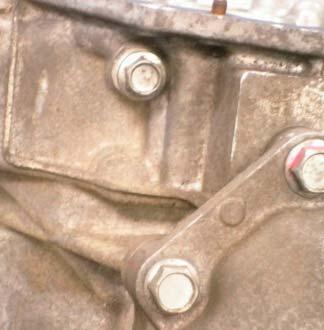
15 Transmission Disassembly Remove clip holding in case center Remove the oil pan Remove the manual lever Remove the filter Remove the wire harness ROM (Read Only Memory Module) Remove marked bolts to remove valve body. Remove bell housing bolts. NOTE LOCATION OF THE 5 LONG BOLTS 13


16 Transmission Disassembly Separate bell housing from main case Remove the reduction gear and differential Remove o-ring, selective washer and upper baffle Remove pump driven gear chain and drive gear Remove the pump bracket to lower baffle and lower baffle. 14


17 Transmission Disassembly Remove the pump. There is one external bolt. Remove stator support. Remove detent spring Remove forward drum Remove planetary assembly Remove reverse clutch, reverse clutch retainer and piston Remove case rear cover bolt 15


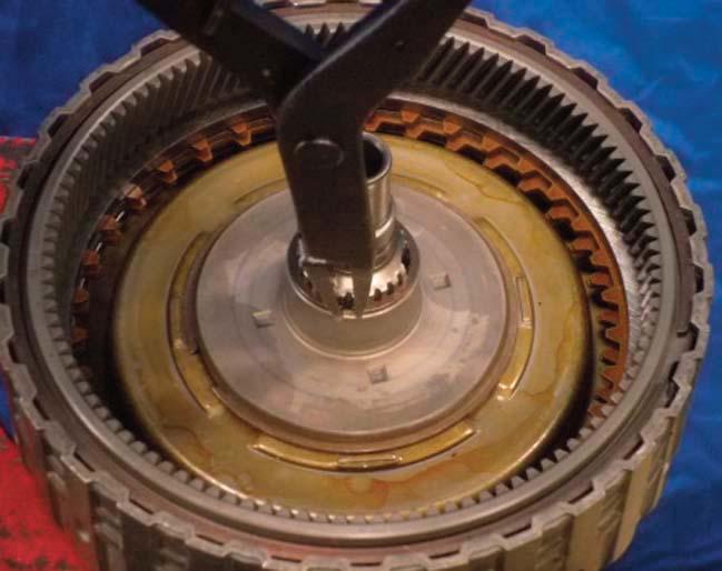
18 Subassemblies Pulleys and Drive Belt Assembly Note the direction of the belt Always wire tie belt, if not, belt could come apart Compress the Driven Pulley Tool used is an11 inch two jaw puller with 5 inch duct flange. Purchased at a plumbing supply warehouse. Chrysler tool 9874 Remove driven pulley Remove the driven pulley shim Remove the drive pulley 16


19 Secondary Pulley Subassemblies Pulleys and Drive Belt Assembly Using a bearing splitter under the bearing, on the driven pulley, press bearing and gear off pulley assembly Using the same clamp, press the pulley halves apart. Place a bucket under the pulley assembly. There are 12 6mm balls on the inside of the pulley assembly that need to be saved. 17


20 Secondary Pulley - Continued Subassemblies Pulleys and Drive Belt Assembly Compress balance piston Remove piston retainer snap ring Inspect both the shaft groove, pulley groove and the twelve 6mm balls for any wear. If any wear is found, the pulley shaft and balls will need to be replaced. Carefully install the upper secondary pulley half onto the lower pulley half/shaft. This is a very tight fit. Do not force these halves together. They should slide up and down freely. 18


21 Subassemblies Secondary Pulley - Continued Pulleys and Drive Belt Assembly Insert the twelve 6mm balls into the slots, 4 balls per slot. Insert one ball in each slot, lightly tap each ball with a punch until, the ball is seated into the bottom of each slot. After all the balls have been seated, slide the upper pulley half up so the snap ring groove is just completely accessible. NOTE Install the snap ring that retains the balls. THERE IS A HUMP IN THE SNAP RING THAT NEEDS TO LINE UP WITH THE NOTCH IN THE UPPER PULLEY. Install the piston return spring 19


22 Subassemblies Secondary Pulley - Continued Pulleys and Drive Belt Assembly Install piston seal, make sure the ends overlap correctly Install secondary piston then install secondary balance piston Press secondary piston down just enough to install the piston retaining snap ring. You may need to tap the balance piston down to get the snap ring in. Once the snap ring is installed, continue pressing the piston until it is completely seated. Install the bearing on the secondary shaft with the lip facing down or towards the pulley. Press the bearing onto the secondary shaft 20


23 Subassemblies Secondary Pulley - Continued Pulleys and Drive Belt Assembly Install washer onto bearing. Install the pinion gear with the raised lip facing down or towards the pulley. Press the pinion gear onto secondary shaft. Install the retaining nut. Torque to 185 Ft. Lbs. than stake nut. 21


24 Subassemblies Primary Pulley Pulleys and Drive Belt Assembly Using a bearing splitter, press the bearing off the primary shaft. Press the pulley halves apart. Place a container under the press, there are six 6mm balls that will be saved. 22


25 Subassemblies Primary Pulley Pulleys and Drive Belt Assembly Inspect the groove in the shaft and the pulley for wear, also inspect the six 6mm balls for wear. Install one 6mm ball in each of the three grooves, using a punch, lightly tap each ball down until it is fully seated. Each slot takes 2 balls. Lift the upper pulley half just enough so that the entire slot for the snap ring is exposed. Install the snap ring that retains the balls, with the hump in the snap ring, into the notch in the pulley 23


26 Subassemblies Primary Pulley - Continued Pulleys and Drive Belt Assembly Install a new primary piston seal aligning the ends correctly. As you can see, the two ends overlap each other. Install piston into the upper pulley half, then press the piston onto the secondary shaft. Once the piston is fully seated, lift up on the upper pulley half, make sure it moves freely up and down. Install the bearing retainer with the groove facing up. Then press the bearing onto the primary shaft until it is fully seated. 24


 Install thrust")


27 Subassemblies Rear Cover Reassembly Install primary pulley into the end cover with new o-ring on the bolts. Torque to 33 Ft. Lbs. (45Nm) Install thrust washer for secondary pulley Install drive belt with arrow pointing to the left. Compress secondary pulley, using new o-ring on the bolts. Torque Bolts to 33 Ft. Lbs. (45N). 25


28 Subassemblies Rear Cover Reassembly - Continued Install the spring, onto the ratio control lever, with cupped washer facing the lever. Install the lever into the case, with the lip, on the lever top half, of the primary pulley. Install the rod that the ratio control lever rides on. Pump 26


29 Subassemblies Pump - Continued The flow control valve is a high wear part Sonnax valve 33510N-01 Notches are installed facing down Notches facing down Install the sleeve assembly with dot facing this bolt hole Install pump shaft Dots on rotor face down Install rotor dots down Install pump vanes Install pump cover gasket Torque cover bolts 19 Ft. Lbs. (26Nm) 27

30 Subassemblies Forward Clutch Forward Clutch Disassembly 28


31 Subassemblies Remove Input Shaft Remove the snap ring and planetary ring gear Remove the snap ring, pressure plate clutches and steels Compress the retainer and remove snap ring Forward Clutch Reassembly Remove forward clutch balance piston Install apply pistons and return springs Install balance piston Install piston retainer/springs and snap rings Install cushion plate dish down Start with steel plate, then friction plate, alternating ending with a friction plate 29


32 Subassemblies Forward Clutch Reassembly - Continued Install forward clutch pressure plate Check clutch pack clearance ( Nm) Install ring gear and lower snap ring Install ring gear and upper snap ring Replace input shaft sealing rings Planetary Install input shaft and snap ring Inspect teeth, pinions for excessive play and pinion washers for wear. 30


33 Subassemblies Differential and Reduction Gear NOTE ITS GOOD PRACTICE TO MARK THE SIDE AND SPIDER GEARS AND KEEP THEM IN THEIR RESPECTIVE PLACES UPON REASSEMBLY. Remove ring gear Remove differential roll pin Remove the shaft that holds in the spider gears Rotate the spider gears 90 then remove the gears and the washers Remove both side gears and washers 31


34 Subassemblies Differential and Reduction Gear - Continued Inspect the spider gears, spider gear washers, side gears and washers for any pitting, galling or wear. Also inspect the differential carrier and gear pockets for wear. Inspect the spider gear shaft and spider gears for wear. Replace any worn parts. Install both side gears and washers. Install the spider gears and washers Rotate spider gears 90 make sure the washer lines up with the hole in differential carrier. Install spider gear shaft Install roll pin Remove both differential side bearings. 32


35 Reduction Gear Subassemblies Differential and Reduction Gear - Continued There are flats on the reduction gear shaft. Then mount the transfer gear into a vise against these flats. Use an impact and socket to remove the retaining nut. Using a bearing splitter, remove both bearings from the reduction gear. Press both bearings onto the reduction gear. Torque to 185 Ft. Lbs. (250Nm) 33

36 Valve Body Remove stepper motor solenoids Remove pressure sensors 34
37 Valve Body - Continued Remove the two bolts holding valve body together, separate valve body halves Remove separator plate 35
38 Valve Body - Continued Remove filter screen Flip valve body over 36
39 Valve Body - Continued Remove separator plate Remove check valve and screens 37

40 Valve Body - Continued Item Number Valve Spring Height Wire Diameter Spring Diameter 1 Solenoid Regulator Valve in..053 in..424 in. 2 Select Control Valve in..042 in..387 in. 3 Select Switch Valve.896 in..030 in..336 in. 4 Lock Up Control Valve in..039 in..479 in. 5 6 Clutch Reducing Regulator Valve Bore Plug Elevated Spring Seat Towards Valve Secondary Pulley Control Valve.915 in..024 in..304 in..823 in..029 in..464 in. Valves that Wear Solenoid Regulator Valve Lockup Plunger and Sleeve 38

41 Valve Body - Continued Item Number Valve Spring Height Wire Diameter Spring Diameter 1 Solenoid Pulley Regulator Valve 1.108in..031 in..423 in. 2 Pressure Regulator Valve in..033 in..424 in. 3 Pressure Regulator Valve in..067 in..394 in. 4 TCC Regulator Valve in..046 in..473 in. 5 Manual Valve N/A N/A N/A Valves that Wear Secondary Pulley Regulator Valve Pressure Regulator Valve 1 Pressure Regulator Valve 2 TCC Regulator Valve 39


42 Valve Body - Continued Valve Spring Height Wire Diameter Spring Diameter Ratio Control Valve in..020 in..350 in. 40

43 Valve Body Reassembly Center valve body, check valve and screens installed Install separator plate 41
44 Valve Body Reassembly - Continued Tightly hold valve bodies together, flipping valve bodies over Install filter screen 42


45 Valve Body Reassembly - Continued Install separator plate Install upper valve body Torque through bolts to 70 In. Lbs. Replace both pressure switches and o-rings 43
 1.")


46 Valve Body - Continued C C 4 B 3 14 B 5 2 C C 9 A 8 13 C C C C 1 C 7 12 C C Valve Body - Bolt Lengths A) 1.94 B) C) Torque valve body half bolts to in. lbs. in sequence. Pressure switch torque 70 In. Lbs. Torque stepper motor and solenoid bolts to 70 In. Lbs. Install ratio control valve. Install lever into ratio control motor. 44


, 30 Ft. Lbs.")

47 Reverse Clutch Notch Goes Here Install reverse clutch piston Install reverse clutch, return springs and retainer plate Compress retainer install snap ring Install cushion plate, dish up Install steel plate then friction plate, alternating ending with friction plate. Install the reverse pressure in. ( mm), 30 Ft. Lbs. (45Nm) Using loctite 509 sealer, install end cover onto the main case. Torque bolts to 33 Ft. (45Mn) 45


 and")


48 Reassembly Install torrington bearing and planet carrier Install torrington bearing and sun gear into planet carrier Install torrington bearing Install forward drum, drum is fully seated top of drum even with carrier Install stator support and thrust washer Install TCC o-ring Install new pump seal, install the pump, Torque the inside bolts to 14 Ft. Lbs (19Nm) and outside bolt with o-ring to 20 Ft. Lbs (28Nm) Outside pump bolt 46


49 Reverse Clutch - Continued Install lower oil baffle and pump bracket. Torque baffle bolts 52 In. Lbs. Pump bracket and stator support bolts to 19 Ft. Lbs. Install pump chain and gears Install upper baffle. Torque to 52 In. Lbs. Measuring Pump Gear Clearance Install pin for manual valve shaft and detent spring. Torque bolt to 61 In. Lbs. Measurement A from straight edge to the Measurement B step on gear. To calculate the correct shim. A + B In. (.16mm) Install the selective shim Install differential and transfer gears Install axle seal and front seal Using loctite 509 sealer, install the bell housing bolts marked in yellow. Torque to 33 Ft. Lbs. (45Nm). Bolts marked in yellow 1.67 in(42.8mm) 47


50 Reassembly Chrysler Nissan Install cooler filter Install cooler with new o-ring.torque bolts to 37 In. Lbs. (4Nm) Install cooler filter Install cover with new o-ring. Torque bolts to 37 In. Lbs. (4Nm) Because of the design of these coolers they are very difficult to flush. If there is any kind of contamination in the unit, the cooler should be replaced. Airtest Lube for Ratio Sensor Shaft TCC Apply/Charge Primary Pulley TCC Release Forward Apply Cooler In Cooler Out Reverse Apply Line Pressure Tap Forward Pressure Tap Primary Pressure Tap TCC Release Pressure Tap TCC Apply Pressure Tap Pump Output Line Pressure Secondary Pulley Pressure 48


51 Reassembly - Continued Install case connector into case Tang on case connector faces down towards recessed in case Install case connector clip Lay harness across case Install pin to hold ratio control lever as shown in these pictures. The end of the lever goes into the ratio control motor. The pin holds the lever in the correct position so it will line up with the ratio control sensor. The last picture is just showing the correct positioning of the lever to the sensor, you really cannot see this with the transmission assembled. The picture is just showing what the pin is used for. 49


 Install filter with new o-ring.")
 50")
52 Reassembly - Continued Install valve body and filter bracket Install wiring harness bracket Torque all valve body bolts to 70 In. Lbs. (8 Nm) Install spacer for manual valve shaft Install manual lever onto manual shaft. Tighten nut to 194 In. Lbs. (22Nm) Install filter with new o-ring. Tighten bolts to 70 In. Lbs. (8Nm) Install oil pan and gasket. Tighten bolts to 70 In. Lbs. (8Nm) 50
53 Codes Codes P0700 P0703 P0707 P0708 P0711 P0712 P0713 P0716 P0717 P0721 P0722 P0730 P0741 P0746 P0776 P0777 P0826 P0842 P0843 P0847 P0848 P0850 P0962 P0963 P0966 P0967 P1702 P1723 P1729 Description MIL Request Brake Switch 2 Performance Transmission Range Sensor Circuit Low Transmission Range Sensor Circuit High Transmission Temperature Sensor Performance Transmission Temperature Sensor Low Transmission Temperature Sensor High Input Speed Sensor 1 Circuit Performance Input Speed Sensor 1 Circuit No Signal Output Speed Sensor Circuit Performance Output Speed Sensor Circuit No Signal Incorrect Gear Ratio Torque Converter Clutch Circuit Performance Line Pressure Solenoid Performance Secondary Pressure Solenoid Stuck Off (High Pressure) Secondary Pressure Solenoid Stuck On (Low Pressure) Up/Down Shift Switch Circuit Primary Oil Pressure Sensor Circuit Low Primary Oil Pressure Sensor Circuit High Secondary Oil Pressure Sensor Circuit Low Secondary Oil Pressure Sensor Circuit High Park/Neutral Switch Performance Pressure Control Solenoid A Control Circuit Low Pressure Control Solenoid A Control Circuit High Pressure Control Solenoid B Control Circuit Low Pressure Control Solenoid B Control Circuit High Primary Oil Pressure Sensor/Secondary Oil Pressure Sensor Correlation Lock Up/Select Control Circuit Transmission Ratio Control Circuit 51
54 Manufacturer Years Sales TD(1) Unit ID Type Audi A4/A6/Cabrio CVT Reference Guide Uses Converter 2004-Up 200,000 01J ZF No Fluid(2) G A25 Quantity 5Qts Transmission Fluid Change Service Interval (3) 115,000 miles Dodge Caliber 2007-Up 1 mil/year JF011e Jatco Yes CVTF+4 7.5Qts 64,000 miles Ford/Mercury 500, Freestyle, Montego ,000 CFT30 ZF Yes Ford CVT 5Qts 30,000 severe use Honda Civic/ Insight Jeep Compass/Patriot 1996-Up 500,000 Varies Aisin No/Start Clutch Honda CVT 3-3.5Qts 30,000 miles (2) 2007-Up 1 mil/year JF011F Jatco Yes CVTF+4 7.5Qts 64,000 miles Mini ,000 CFT25/27 ZF No Esso EXL Qts. 30,000 miles(2) Nissan Altima 2007-Up 1 mil/year RE0F09A/B Jatco Yes CVTNS Qts. 60,000 miles Cube 2003-Up 1 mil/year RE0F08A Jatco Yes CVT NS2 7.9Qts. 60,000 miles Maxima 2007-Up 1 mil/year RE0F09B Jatco Yes CVT NS Qts. 60,000 miles Murano 2003-Up 1 mil/year RE0F09B Jatco Yes CVT NS Qts. 60,000 miles Rogue 2008-Up 1 mil/year RE0F09A Jatco Yes CVT NS2 10.5Qts. 60,000 miles Sentra 2007-Up 1 mil/year RE0F10A Jatco Yes CVT NS2 8.8Qts. 60,000 miles Versa 2007-Up 1 mil/year RE0F08A Jatco Yes CVT NS2 7.9Qts. 60,000 miles Saturn Ion/Vue ,000 VT20/25-E Jatco Yes DEX CVT Qts. 50,000 miles (1) - Combined 1 million/year (Dodge/Jeep/Nissan) (2) - OE Fluid Recommended (3) - Honda uses Maintenance Minder monitors variables to determine when the right time to change Oil. Mini models use Condition Based Servicing (CBS) which replaces the older inspection style service regime. CBS uses sensors to determine right time for Oil Change. 52
55 CVT Reference Guide Continued Manufacturer Years Common Issues (4) Stepper Motor Sources Audi A4/A6/Cabrio 2004-Up Shudder, Pump, Noises, TCM Do Not Use Stepper Motor Special Tools (5) Dodge Caliber 2007-Up Noise/Stepper Motor Transtar Sourcing Yes Yes Ford/Mercury 500, Freestyle, Montego Noises, Shudder, Belt, Bearing Do Not Use Stepper Motor Yes Honda Civic/ Insight 1996-Up Shudder, Bearings, Belt Do Not Use Stepper Motor Yes Jeep Compass/Patriot 2007-Up Shudder, Belt, Stepper Motor Yes Mini Shudder,Noise,Belt,Stepper Valve Body Pro Yes Nissan Altima 2007-Up Shudder,Stepper Motor Yes Cube 2003-Up Shudder,Stepper Motor Yes Maxima 2007-Up Shudder, Stepper Motor Yes Murano 2003-Up Shudder, Stepper Motor Yes Rogue 2008-Up Shudder,Stepper Motor Yes Sentra 2007-Up Shudder,Stepper Motor Yes Versa 2007-Up Shudder,Stepper Motor GFX/Valve Body Pro Yes Saturn Ion/Vue Shudder,Stepper Motor,Noises,Valve Body,Belt (NEW Valve Body which includes Stepper Motor) Valve Body Pro Yes (4) - Common Issues - Symptoms/Diagnosis If the unit does not move in either direction, something catastrophic is typically wrong. If the unit moves only in one direction, look for clutch or hydraulic issue, which can affect its movement in that direction. Reverse operation is fixed at one ratio. Noises which are present in Park/Neutral, but go away in gear, are usually related to the input shaft/support. Some Honda CVT S will have noise in reverse - This is normal. A Shudder on takeoff usually related to internal leaks, low pressure, damaged clutches, electrical, driveability or strategy. Electrical issues including the TCM, will usually set a specific code. (5) - Special Tools Needed to remove belts and pulleys or improvise. 53
56 Manufacturer Years OE Vehicle Warranty Audi A4/A6/Cabrio Dodge Caliber Ford/Mercury 500, Freestyle, Montego Honda Civic/ Insight Jeep Compass/Patriot Dealer Unit Warranty Soft Part Available (6) 2004-Up 10yr/100,000 up to mo/12,000 Transtar New 2007-Up CVT Reference Guide Continued yr/35,000 miles, 2008 up 5yr/100,000 miles yr/60,000 miles 3yr/100,000 3yr/unlimited miles 1996-Up 5yr/60,000 miles 3yr/30, Up 5yr/100,000 miles 3yr/100,000 Mini Extended in some cases 2yr/Unlimited Nissan Altima 2007-Up Factory 10yr/120,000 Warranty 12mo/12,000 Cube 2003-Up Factory 10yr/120,000 Warranty 12mo/12,000 Maxima 2007-Up Factory 10yr/120,000 Warranty 12mo/12,000 Murano 2003-Up Factory 10yr/120,000 Warranty 12mo/12,000 Rogue 2008-Up Factory 10yr/120,000 Warranty 12mo/12,000 Transtar, Natpro GFX Transtar, Natpro GFX Transtar, Natpro GFX Transtar, Natpro GFX Transtar, Natpro GFX Transtar, Natpro GFX Transtar, Natpro GFX Transtar, Natpro GFX Transtar, Natpro GFX Transtar, Natpro GFX Sentra 2007-Up Factory 10yr/120,000 Warranty Transtar, Natpro 12mo/12,000 GFX Versa 2007-Up Factory 10yr/120,000 Warranty Transtar, Natpro 12mo/12,000 GFX Saturn Ion/Vue Not Applicable 12mo/12,000 Transtar,Natpro GFX Hard Parts Available (7) Various Used New Limited Limited New OEM Limited New Limited New Limited New Limited New Limited New Limited New Limited New Limited New Limited New New & Used Limited (6) - Soft Parts are available through Transtar/NatPro/GFX such as frictions,seal kits. They also carry the most common failure parts. Belts Available New (7) - Hard Parts such as variators, pumps, planets, drums, hubs and sheaves are typically not stocked and will probably be sourced as used parts. Valve Bodies are typically not remanufactured. SERVICE Repair - After the Overhaul or replacement, all CVT s require adaptation. MINI CVT requires the BMW scanner to perform this step. Yes TBA No Yes No Yes Yes Yes Yes Yes Yes Yes Yes Yes 54
ATRA WEBINAR Chrysler CVT-2 Introduction
 ATRA WEBINAR Chrysler CVT-2 Introduction Sponsored By: Presented by: Steve Garrett ATRA Today s Presentation Sponsored By: Lwiggins@ATRA.com Connections Handout Questions Survey Thanks A special thanks
Technical Service Bulletin
 Page 1 of 41 MITSUBISHI MOTORS Technical Service Bulletin SUBJECT No: NOISE FROM CVT AT ALL ENGINE SPEEDS DATE: February, 2015 MODEL: See below CIRCULATE TO: I[ ]GENERAL MANAGER I [ X l PARTS MANAGER I
Jatco 5 Speed ATRA. All Rights Reserved. Printed in U.S.A.
 1 2 3 Table Of Contents Transmission Diassembly... 4 Front Pump... 16 Reverse/High Clutch Drum... 18 Direct Clutch Drum... 22 Low Clutch Drum... 26 Planetary Gearsets... 29 Transfer Gear/Reduction Gear...
HIGH PERFORMANCE TRANSMISSION PARTS Instructions. Line Pressure Booster Kit. TCC Control Plunger Valve Kit. Line Pressure Modulator Plunger Valve Kit
 Performance Pack Ford 4R100 Part No. HP-4R100-01 Line Pressure Booster Kit Line-to-Lube Pressure Regulator Valve Line Pressure Booster Kit Valve Sleeve O-Rings (2) TCC Control Plunger Valve Kit Front Lube/Drainback
Transaxle. 1. Mount the transaxle to Bench Mounted Holding Fixture T57L-500-B.
 «1997 Aspire Table of Contents» «Group 07: TRANSAXLE» «Section 07-01: Transaxle, Automatic» «DISASSEMBLY» Transaxle CAUTION: To prevent dirt from entering the transaxle, it should be disassembled and kept
DISASSEMBLY AND ASSEMBLY
 307-01-1 Automatic Transaxle/Transmission 307-01-1 DISASSEMBLY AND ASSEMBLY Transaxle Special Tool(s) Dial Indicator Gauge With Holding Fixture 100-002 (TOOL-4201-C) Special Tool(s) Test Plate Screw Set,
TRANSMISSION PARTS Instructions
 TRANSMISSION PARTS Instructions Sure Cure Kit Part No. SC-4T65E GM 4T65-E Valve Body Parts Boost Valve Kit 84754-30K Patent No. 6,832,632 TCC Apply Valve Kit 84754-43K Patent No. 7,100,753 TCC Regulated
2000 Jeep Truck Cherokee 4WD L6-4.0L VIN S
 2000 Jeep Truck Cherokee 4WD L6-4.0L VIN S Vehicle» Transmission and Drivetrain» Automatic Transmission/Transaxle» Service and Repair» 30-40LE (AW4) 4 Speed» Overhaul (Transmission)» Disassembly DISASSEMBLY
2001 Dodge RAM 3500 PICKUP
 1 of 76 9/14/2012 7:02 PM 2001 Dodge RAM 3500 PICKUP Submodel: Engine Type: L6 Liters: 5.9 Fuel Delivery: FI Fuel: DIESEL Subarticles MANUAL- NV3500 - DISASSEMBLY MANUAL- NV3500 - DISASSEMBLY MANUAL -
GM 4L80-E, 4L85-E SURE CURE KIT
 GM 4L80-E, 4L85-E SURE CURE KIT PART NUMBER SC-4L80E INSTALLATION GUIDE Parts are labeled here in order of installation. See page 2 for details on Sure Cure kit contents. See Sure Cure instruction booklet
GM 4L80-E, 4L85-E SURE CURE KIT
 GM 4L80-E, 4L85-E SURE CURE KIT PART NUMBER SC-4L80E INSTRUCTION BOOKLET Parts are labeled here in order of installation. See page 2 for details on Sure Cure kit contents. See Sure Cure instruction booklet
ABBREVIATIONS USED IN THIS
 IN10 INTRODUCTION ABBREVIATIONS USED IN THIS MANUAL ABBREVIATIONS USED IN THIS MANUAL ATF Automatic Transmission Fluid B 0 Overdrive Brake B 2 Second Brake B 3 No. 3 Brake C 0 Overdrive Direct Clutch C
COMPONENT LOCATOR > DISASSEMBLED VIEWS
 Page 1 of 26 Service Manual: AUTOMATIC TRANSAXLE - 4T65-E - OVERHAUL COMPONENT LOCATOR > DISASSEMBLED VIEWS Fig 1: Case and Associated Parts Disassembled View (1 of 4) 2004 Buick LeSabre 3.8L Eng Limited
AUTOMATIC TRANSMISSIONS. General Motors Corp. Hydra-Matic 4L60-E Overhaul
 1997-98 AUTOMATIC TRANSMISSIONS General Motors Corp. Hydra-Matic 4L60-E Overhaul APPLICATION TRANSMISSION APPLICATIONS Application Corvette Transaxle 4L60-E IDENTIFICATION The 4L60-E transmission can be
TRANSFER CASE Mitsubishi Montero APPLICATION DESCRIPTION TESTING 4WD INDICATOR CONTROL UNIT (MONTERO) DETECTION SWITCH
 DETECTION SWITCH") TRANSFER CASE 1993 Mitsubishi Montero 1991-94 TRANSFER CASES Mitsubishi Dodge; Ram-50 Mitsubishi; Pickup, Montero APPLICATION TRANSFER CASE APPLICATIONS TABLE Application (1) Transmission Model Dodge 1991-93
TRANSFER CASE 1993 Mitsubishi Montero 1991-94 TRANSFER CASES Mitsubishi Dodge; Ram-50 Mitsubishi; Pickup, Montero APPLICATION TRANSFER CASE APPLICATIONS TABLE Application (1) Transmission Model Dodge 1991-93
AUTOMATIC TRANSMISSIONS Mitsubishi F3A20 Series TRANSMISSION APPLICATION TABLE
 Article Text ARTICLE BEGINNING AUTOMATIC TRANSMISSIONS Mitsubishi F3A20 Series APPLICATION TRANSMISSION APPLICATION TABLE Vehicle Application Transmission Model Colt 3-Speed (1990-94)... F3A21 Colt Vista
TCI Turbo 400 Full Manual Valve Body. Shift Pattern: Park Reverse Neutral First Second Third. NOTE: You must reuse stock manual control valve.
 TCI 221100 Turbo 400 Full Manual Valve Body Shift Pattern: Park Reverse Neutral First Second Third This Kit Contains: (1) Turbo 400 Full Manual Valve Body (1) Separator Plate & Gaskets (1) Pressure Regulator
2002 F-Super Duty /Excursion Workshop Manual
 Page 1 of 25 SECTION 307-01: Automatic Transaxle/Transmission 2002 F-Super Duty 250-550/Excursion Workshop Manual ASSEMBLY Procedure revision date: 05/23/2001 Transmission Special Tool(s) Remover, O-Ring
2001 Chevrolet Corvette AUTOMATIC TRANSMISSIONS Hydra-Matic 4L60-E - Overhaul
 2001-03 AUTOMATIC TRANSMISSIONS Hydra-Matic 4L60-E - Overhaul APPLICATION CAUTION: Flush oil cooler and oil cooler lines prior to transmission installation. Oil cooling system contamination may cause premature
MANUAL TRANSAXLE Return to Main Table of Contents
 MANUAL TRANSAXLE Return to Main Table of Contents GENERAL... 2 MANUAL TRANSAXLE CONTROL... 12 SHIFT LEVER ASSEMBLY... 14 MANUAL TRANSAXLE... 15 MANUAL TRANSAXLE ASSEMBLY... 17 FIFTH SPEED SYNCHRONIZER
ALLISON 1000 SIGNATURE SERIES
 ALLISON 1000 SIGNATURE SERIES 2001-2010 DURAMAX GPZ 1 FLUID CAPACITY INSTALLATION In our RevMax performance transmission we require you to use DEXRON 3 fluid and are shipped empty due to the regulations
 Page 1 of 22 SECTION 307-01: Automatic Transaxle/Transmission 4R70E/4R75E ASSEMBLY Procedure revision date: 05/29/2009 Transmission Printable View (1554 KB) Special Tool(s) Air Test Plate, Transmission
46RE, 46RH, 47RE, 47RH ZIP KIT
 46RE, 46RH, 47RE, 47RH ZIP KIT PART NUMBER 46-47RHE-ZIP QUICK GUIDE Parts are labeled here in order of installation. See other side of sheet for details on Zip Kit contents. installation Diagram 7 1 Separator
2005 Toyota RAV AUTOMATIC TRANSMISSIONS U240E & U241E Overhaul
 2001-05 AUTOMATIC TRANSMISSIONS U240E & U241E Overhaul APPLICATION CAUTION: Flush oil cooler and oil cooler lines prior to transaxle installation. Oil cooling system contamination may cause premature transaxle
In the last issue of GEARS,
 JATCO CVT and DaimlerChrysler by Sean Boyle Electronic and Computer Part 2 Control Systems In the last issue of GEARS, we began looking at the JATCO Continuously Variable Transmission (CVT) being offered
3.2 DRIVE TORQUE HUB. Roll, Leak and Brake Testing SECTION 3 - CHASSIS & TURNTABLE. 3-2 JLG Lift
 3.2 DRIVE TORQUE HUB Roll, Leak and Brake Testing 10 LUG PATTERN Torque-Hub units should always be roll and leak tested before disassembly and after assembly to make sure that the unit's gears, bearings
BRAKE SYSTEM Nissan 240SX DESCRIPTION BRAKE BLEEDING * PLEASE READ FIRST * BLEEDING PROCEDURES ADJUSTMENTS BRAKE PEDAL HEIGHT SPECS TABLE
 BRAKE SYSTEM 1990 Nissan 240SX 1990 BRAKE SYSTEMS Nissan Disc & Drum Axxess, Maxima, Pathfinder, Pickup, Pulsar NX, Sentra, Stanza, 240SX, 300ZX DESCRIPTION All brake systems are hydraulically operated
SPECIAL TOOLS Dodge Pickup 5.9L Eng R3500. Fig 1: Identifying Remover C-3985-B (Special Tool) 9/6/13 Printer Friendly View
 9/6/13 Printer Friendly View") Procedures 2003 Dodge Pickup 5.9L Eng R3500 manual transmission SPECIAL TOOLS Fig 1: Identifying Remover C-3985-B (Special Tool) www2.prodemand.com/print/index?content=tabs&module=true&tab=true&terms=true&ymms=false&classname=
Procedures 2003 Dodge Pickup 5.9L Eng R3500 manual transmission SPECIAL TOOLS Fig 1: Identifying Remover C-3985-B (Special Tool) www2.prodemand.com/print/index?content=tabs&module=true&tab=true&terms=true&ymms=false&classname=
EATON 751, 781 HYDROSATIC TRANSAXLE
 EATON 751, 781 HYDROSATIC TRANSAXLE Table Of Contents Page 1 of 1 751, 851, 771, AND 781 HYDROSTATIC TRANSAXLE TRANSAXLES 751, 851 TRANSAXLE WITH CHARGE PUMP 781 SERIES HYDROSTATIC TRANSAXLE AXLE HOUSING
DRIVE AXLE Volvo 960 DESCRIPTION & OPERATION AXLE IDENTIFICATION DRIVE AXLES Volvo Differentials & Axle Shafts
 DRIVE AXLE 1994 Volvo 960 1994 DRIVE AXLES Volvo Differentials & Axle Shafts 960 DESCRIPTION & OPERATION All 960 station wagon models use type 1041 rear axle assembly. All 960 4-door models use type 1045
JF506E (JA5A-EL/5F31J/RE5F01A/09A)
") FWD 5 Speed FWD 5 Speed 750 699 284 730 281 712 281 796 282 280 869 283 586 596 868 616 864 866 142 561 961 331 981 865 971 330 122 551 040 257 862 650 180 260 261 259 022 790 A A 698 715 077 293* 292
FWD 5 Speed FWD 5 Speed 750 699 284 730 281 712 281 796 282 280 869 283 586 596 868 616 864 866 142 561 961 331 981 865 971 330 122 551 040 257 862 650 180 260 261 259 022 790 A A 698 715 077 293* 292
Geo Prizm ( LSi) Toyota Celica 1.8L (1994)
 Toyota Celica 1.8L (1994)") Page 1 of 140 ARTICLE BEGINNING APPLICATION TRANSMISSION APPLICATIONS Application Geo Prizm (1993-94 LSi) Toyota Celica 1.6L (1993) Celica 1.8L (1994) Celica 2.2L (1993) Corolla 1.8L MR2 Paseo Transaxle
Page 1 of 140 ARTICLE BEGINNING APPLICATION TRANSMISSION APPLICATIONS Application Geo Prizm (1993-94 LSi) Toyota Celica 1.6L (1993) Celica 1.8L (1994) Celica 2.2L (1993) Corolla 1.8L MR2 Paseo Transaxle
2003 E-Series Workshop Manual
 Page 1 of 20 SECTION 307-01B: Automatic Transmission 4R70W 2003 E-Series Workshop Manual ASSEMBLY Procedure revision date: 04/27/2006 Transmission Printable View (1828 KB) Special Tool(s) Dial Indicator
TRANSMISSION PARTS Instructions. Solenoid Regulator Valve Retainer Shim. Main Pressure Regulator Valve
 TRANSMISSION PARTS Instructions Sure Cure Kit Part No. SC-AODE NOTE: This kit is fully compatible with '91 '95 only. Identified by alignment pins 13mm heads. This kit will not work on '96 Later units.
AUTOMATIC TRANSMISSIONS ZF 4HP 18
 AUTO TRANS OVERHAUL - ZF 4HP 18 Article Text 1991 Eagle Premier For Dan's Transmission Service 10 Jefferson Place Fort Walton Beach FL 32548 1997 Mitchell Repair Information Company, All Rights Reserved.
1991 TRANSMISSION SERVICING Automatic Transmission. Mitsubishi: Eclipse, Galant, Mirage, Montero, Pickup, Precis, 3000GT
 Article Text ARTICLE BEGINNING 1991 TRANSMISSION SERVICING Automatic Transmission Mitsubishi: Eclipse, Galant, Mirage, Montero, Pickup, Precis, 3000GT IDENTIFICATION MITSUBISHI AUTOMATIC TRANSMISSION APPLICATIONS
2013 NATEF Task Area A-2 Automatic Transmission7-2013
 2013 NATEF Task Area A-2 Automatic Transmission7-2013 A. General Transmission & Transaxle Diagnosis B. Transmission & Transaxle Maintenance & Adjustment C. In-Vehicle Transmission & Transaxle Repair D.
TCI E4OD/4R100 Valve Body Performance Improver Kit
 151 INDUSTRIAL DRIVE ASHLAND, MISSISSIPPI 38603 http://www.tciauto.com TCI 496500 E4OD/4R100 Valve Body Performance Improver Kit TELEPHONE: 662-224-8972 FAX LINE: 662-224-8255 E-MAIL: tech@tciauto.com
TRANSMISSION 6.7 GENERAL HOME. See Figure The transmission is a five-speed constantmesh type housed in an extension of the crankcase.
 TRANSMISSION 6.7 GENERAL See Figure 6-45. The transmission is a five-speed constantmesh type housed in an extension of the crankcase. Mainshaft Neutral Mainshaft st Gear b06x6x Countershaft 4 Out 5 Countershaft
In the last issue of GEARS we went
 A Look Inside the 6-Speed Volkswagen Automatic; Part 2 A Look Inside the 6-Speed Volkswagen Automatic; Part 2 by David Skora In the last issue of GEARS we went over the theory of VW s 09G and 09M 6-speed
MANUAL TRANS OVERHAUL - BORG-WARNER - T56 6-SPEED MANUAL TRANSMISSIONS Borg-Warner T56 (MM6) 6-Speed
 6-Speed") IDENTIFICATION MANUAL TRANS OVERHAUL - BORG-WARNER - T56 6-SPEED 1998 MANUAL TRANSMISSIONS Borg-Warner T56 (MM6) 6-Speed Transmission has 2 identification labels, located on lower left side of case. One
IDENTIFICATION MANUAL TRANS OVERHAUL - BORG-WARNER - T56 6-SPEED 1998 MANUAL TRANSMISSIONS Borg-Warner T56 (MM6) 6-Speed Transmission has 2 identification labels, located on lower left side of case. One
A/C COMPRESSOR SERVICING Article Text 1991 Saab 9000 For Copyright 1997 Mitchell International Friday, October 15, :22PM
 Article Text ARTICLE BEGINNING 1991 GENERAL SERVICING Compressor Service * PLEASE READ THIS FIRST * CAUTION: When discharging air conditioning system, use only approved refrigerant recovery/recycling equipment.
Model 4360 Teardown and Reassembly Instructions
 Clean the outside surface of the transaxle. Place the shifter in neutral position. Remove detent cover screw (item 3), detent cover (item 4), detent springs (item 5), and detent balls (item 6). Use a magnet
Chrysler 46RE, 46RH, 47RE, 47RH SURE CURE KIT
 Chrysler 46RE, 46RH, 47RE, 47RH SURE CURE KIT PART NUMBER SC-46-47RHE-OS INSTALLATION GUIDE Parts are labeled here in order of installation. See other side of sheet for details on Sure Cure kit contents.
AODE ( 96 & LATER) SC-AODE-1. Transmission Reconditioning Kit FULL COMPATIBILITY IMPORTANT VALVE BODY PARTS REASSEMBLY PARTS
 SC-AODE-1. Transmission Reconditioning Kit FULL COMPATIBILITY IMPORTANT VALVE BODY PARTS REASSEMBLY PARTS") AODE ( 96 & LATER) Transmission Reconditioning Kit FULL COMPATIBILITY SC-AODE-1 Full compatibility with 1996 and later units. Identified by alignment pins with 10mm head and.173" pin diameter. IMPORTANT
AODE ( 96 & LATER) Transmission Reconditioning Kit FULL COMPATIBILITY SC-AODE-1 Full compatibility with 1996 and later units. Identified by alignment pins with 10mm head and.173" pin diameter. IMPORTANT
2012 NATEF Task Area A 2 Automatic Transmission
 2012 NATEF Task Area A 2 Automatic Transmission A. General Transmission & Transaxle Diagnosis B. Transmission & Transaxle Maintenance & Adjustment C. In Vehicle Transmission & Transaxle Repair D. Off Vehicle
Volkswagen 095/096/01M, 097/01N, 098/01P
 Volkswagen 095/096/01M, 097/01N, 098/01P FWD 4 Speed 50 20 21 30 31 45 10 A Pump Body Stator 2-4 Brake Clutch (B2) 37 67 36 46 82 B Forward Clutch (K1) Forward Hub 65 69 42 43 C Drive Sun Gear Shell Center
Zoom and Print Options
 1 of 63 8/26/2017, 7:04 AM Vehicle» Transmission and Drivetrain» Transfer Case» Service and Repair» Procedures» Isuzu T150» Overhaul (Unit Repair)» 1. Transfer Case Disassemble Transfer Case Disassemble
6F50 / 6F55 / 6T70 / 6T75
 6F50 / 6F55 / 6T70 / 6T75 FWD 6 Speed 42 80 81 82 83 43 A 41 Differential 84 85 86 87 B 60 Driven Transfer Pinion 50 70 51 169 51 70 C 117 61 139 140 D 5 100 62 Pump Drive 141 90 142 Drive Transfer 71
DISASSEMBLY TRANSAXLE DISASSEMBLY AND ASSEMBLY. Part 1 Of 3
 2004 Mitsubishi Truck Endeavor V6-3.8L SOHC Vehicle > Transmission and Drivetrain > Automatic Transmission/Transaxle > Service and Repair > Overhaul > F4A5A > Disassembly and Assembly DISASSEMBLY TRANSAXLE
DIFFERENTIALS & AXLE SHAFTS
 DIFFERENTIALS & AXLE SHAFTS 2001 Chevrolet Camaro 2000-01 DRIVE AXLES General Motors Differentials & Axle Shafts Chevrolet; Camaro Pontiac; Firebird DESCRIPTION & OPERATION Drive axle is a semi-floating,
1984 Dodge W250 PICKUP
 1984 Dodge W250 PICKUP Submodel: Engine Type: V8 Liters: 5.2 Fuel Delivery: CARB Fuel: GAS Dana 44 MODELS THROUGH 1984 2. Raise and safely support the vehicle, then remove the wheel hub and bearings as
Assembly. NOTE: Before beginning assembly, perform/inspect the following:
 Page 1 of 31 Home Account Contact ALLDATA Log Out Help DAN GRIMWOOD DAN GRIMWOOD00002 Select Vehicle New TSBs Technician's Reference Component Search: OK 1997 Ford Truck F 150 2WD Pickup V6-4.2L VIN 2
Not Just Another. Apair of new transmissions LET'S PLAY BALL. by Lance Wiggins members.atra.com
 Not Just Another CVT LET'S PLAY BALL Not Just Another CVT by Lance Wiggins members.atra.com Apair of new transmissions were introduced in the 2014 Chevrolet Spark (C Body): The CVT-7 and 1ET35. We ll take
chart for this unit. Let s look at some of the gear
 by David Skora recently began seeing a new 6- speed automatic transmission in some Beetle and Passat vehicles. Built by Aisan, this transmission uses the Leppeletier planetary design. All shift timing
Technical Bulletin # 1251
 Transmission: Subject: Application: Issue Date: CD4E TCC Slip Code Diagnosis Ford, Mercury and Mazda May 2009 CD4E TCC Slip Code Diagnosis Once the check engine light illuminates, the transmission will
ASSEMBLY PROCEDURE. Transmission
 67 ASSEMBLY PROCEDURE Transmission Tools Required 0555-336256 Transmission Bench Cradle 0555-336258 Cross Shaft Pin Remover/Installer (Detent Lever) 0555-336262 Cross Shaft Seal Installer 0555-336263 Cross
23. Planetary Gear and Low Clutch S510212
 Automatic Transmission 23. Planetary Gear and Low Clutch S510212 A: REMOVAL S510212A18 1) Extract the torque converter clutch assembly. 2) Remove
Parts are labeled here in order of installation. See other side of sheet for details on Zip Kit contents. installation Diagram
 FORD 6R140 ZIP KIT PART NUMBER 6R140-ZIP QUICK GUIDE Parts are labeled here in order of installation. See other side of sheet for details on Zip Kit contents. installation Diagram WARNING: If ridge and
BRAKE SYSTEM Toyota Celica DESCRIPTION DRUM BRAKES ADJUSTMENTS BRAKE PEDAL HEIGHT ADJUSTMENTS BRAKE PEDAL FREE PLAY ADJUSTMENTS
 BRAKE SYSTEM 1988 Toyota Celica 1988-89 BRAKES Toyota Celica, Corolla, MR2, Tercel DESCRIPTION The hydraulic brake system uses a tandem master cylinder with a vacuum power assist servo. MR2 and some Celica
RE4-F04A/B (4F20E), JF403E, LJ4A-EL
, JF403E, LJ4A-EL") RE4-F04A/B (4F20E), JF403E, LJ4A-EL FWD 4 Speed 10 50 40 A Bell Housing Pump Body Stator 2-4 Band Reverse Drum 23 24 65 B Hub High Clutch Shell Low Sprag 66 30 31 33 34 C Forward Sprag Forward Clutch Overrun
RE4-F04A/B (4F20E), JF403E, LJ4A-EL FWD 4 Speed 10 50 40 A Bell Housing Pump Body Stator 2-4 Band Reverse Drum 23 24 65 B Hub High Clutch Shell Low Sprag 66 30 31 33 34 C Forward Sprag Forward Clutch Overrun
TRANSMISSION 6.7 GENERAL HOME. See Figure The transmission is a five-speed constantmesh type housed in an extension of the crankcase.
 TRANSMISSION 6.7 GENERAL See Figure 6-46. The transmission is a five-speed constantmesh type housed in an extension of the crankcase. b06x6x Neutral st Gear Mainshaft Mainshaft 4 5 4 5 Countershaft Out
4T65E. FWD 4 Speed. E Final Drive Sun Gear Shaft Final Drive Ring Gear Output Shaft. Side Cover. 2nd Clutch Drum. Support
 4T65E FWD 4 Speed 2 102 181 185 187 183 182 182 186 141 150 300 150 A 3 184 B Side Cover Output Shaft 153 152 151 267 69 125 97 135 268 70 71 146 38 39 37 36 40 C Support Rev. Band 2nd Clutch Drum 2nd
DISASSEMBLY AND ASSEMBLY
 205-03-1 Front Drive Axle/Differential Ford 8.8-Inch Ring Gear 205-03-1 DISASSEMBLY AND ASSEMBLY Axle Front Drive Special Tool(s) 2-Jaw Puller 205-D072 (D97L-4221-A) Special Tool(s) Carrier Bearing Replacer
VAG-ID.RU Ремонт АКПП ZF 5HP19. Automatic Transmission Spare Parts Catalog
 ZF 5HP19 Automatic Transmission Spare Parts Catalog Warranty Information Warranty coverage for ZF passenger car transmission spare parts and kits covers the first 12 months after installation in the vehicle,
ASSEMBLY PROCEDURE AUTOMATIC TRANSMISSION 5A-173. Transmission
 AUTOMATIC TRANSMISSION 5A-173 ASSEMBLY PROCEDURE Transmission Tools Required 0555-336256 Transmission Bench Cradle 0555-336258 Cross Shaft Pin Remover/Installer (Detent Lever) 0555-336262 Cross Shaft Seal
Service Manual. #19 Gearmatic Winch
 Allis Chalmers Service Manual #19 Gearmatic Winch Service Manual THIS IS A MANUAL PRODUCED BY JENSALES INC. WITHOUT THE AUTHORIZATION OF ALLIS CHALMERS OR IT S SUCCESSORS. ALLIS CHALMERS AND IT S SUCCESSORS
2.2L 4-CYL - VIN [S]
![2.2L 4-CYL - VIN [S]](/thumbs/72/67564355.jpg "2.2L 4-CYL - VIN [S]") 2.2L 4-CYL - VIN [S] 1994 Toyota Celica 1994 ENGINES Toyota 2.2L 4-Cylinder Celica NOTE: For repair procedures not covered in this article, see ENGINE OVERHAUL PROCEDURES - GENERAL INFORMATION article
2.2L 4-CYL - VIN [S] 1994 Toyota Celica 1994 ENGINES Toyota 2.2L 4-Cylinder Celica NOTE: For repair procedures not covered in this article, see ENGINE OVERHAUL PROCEDURES - GENERAL INFORMATION article
ASSEMBLY. Transmission Automatic Transaxle/Transmission. Special Tool(s) Alignment Set, Fluid Pump 307-S039 (T74P X) Special Tool(s)
 Alignment Set, Fluid Pump 307-S039 (T74P X) Special Tool(s)") 307-01-1 Automatic Transaxle/Transmission 307-01-1 ASSEMBLY Transmission Special Tool(s) Adjustment Set, Transmission Band 307-S022 (T71P-77370-A) Special Tool(s) Alignment Set, Fluid Pump 307-S039 (T74P-77103-X)
307-01-1 Automatic Transaxle/Transmission 307-01-1 ASSEMBLY Transmission Special Tool(s) Adjustment Set, Transmission Band 307-S022 (T71P-77370-A) Special Tool(s) Alignment Set, Fluid Pump 307-S039 (T74P-77103-X)
NOTE: Clean and inspect all components. Replace any components which show evidence of excessive wear or scoring.
 ASSEMBLY (AUTOMATIC 545RFE)... ASSEMBLY NOTE: Apply trans jell or petroleum jelly to all slide portions, rolling contacts surfaces, thrust surfaces etc. to prevent burnout during initial operation. Lubricate
SECTION 3A FRONT DRIVE AXLE TABLE OF CONTENTS SPECIFICATIONS GENERAL SPECIFICATIONS. Description Drive Shaft Type. CV Joint Axle Housing Type
 SECTION 3A FRONT DRIVE AXLE TABLE OF CONTENTS Specifications........................ 3A-1 General Specifications.................. 3A-1 Fastener Tightening Specifications......... 3A-2 Component Locator...................
Nissan RL/RE4-F03A/V, RE4-F03B
 Nissan RL/RE4-F03A/V, RE4-F03B FWD 4 Speed A 10 50 51 52 40 53 23 24 Bell Housing 54 54 Pump Body 55 Stator 2-4 Band 26 27 Reverse Drum B High Clutch Hub Shell Low Sprag Low / Reverse Clutch 30 31 33 34
REAR DRIVE SHAFT (3S GTE ENGINE)
") SA52 REAR DRIVE SHAFT (3SGTE ENGINE) COMPONENTS SA53 NOTICE: The axle bearing could be damaged if it is subjected to the vehicle weight, such as when moving the vehicle with the drive shaft removed. Therefore,
SA52 REAR DRIVE SHAFT (3SGTE ENGINE) COMPONENTS SA53 NOTICE: The axle bearing could be damaged if it is subjected to the vehicle weight, such as when moving the vehicle with the drive shaft removed. Therefore,
 Page 1 of 10 Main Components and Functions Torque Converter 1 Cover (Part of 7902) 2 Converter Damper Plate 3 O-Ring (Part of 7902) 4 Turbine Assembly (Part of 7902) 5 Selective Spacer 6 Thrust Washer
ASSEMBLY. Transmission Automatic Transmission 5R44E and 5R55E. Special Tool(s)
") 307-01-1 Automatic Transmission 5R44E and 5R55E 307-01-1 ASSEMBLY Transmission Special Tool(s) Holding Fixture, Transmission 307-262 (T93T-77002-AH) Special Tool(s) Installer, Transmission Extension Housing
307-01-1 Automatic Transmission 5R44E and 5R55E 307-01-1 ASSEMBLY Transmission Special Tool(s) Holding Fixture, Transmission 307-262 (T93T-77002-AH) Special Tool(s) Installer, Transmission Extension Housing
Troubleshooting The Transmission Hydraulic System
 416B, 426B, 428B, 436B, & 438B BACKHOE LOADERS TRANSMISSION Testing And Adjusting Troubleshooting The Transmission Hydraulic System Make reference to the following warning and pressure tap locations for
1.6L 4-CYL - VIN [E]
![1.6L 4-CYL - VIN [E]](/thumbs/81/84172348.jpg "1.6L 4-CYL - VIN [E]") 1.6L 4-CYL - VIN [E] 1993 Nissan Sentra 1993 NISSAN ENGINES 1.6L 4-Cylinder NX, Sentra * PLEASE READ THIS FIRST * NOTE: For engine repair procedures not covered in this article, see ENGINE OVERHAUL PROCEDURES
1.6L 4-CYL - VIN [E] 1993 Nissan Sentra 1993 NISSAN ENGINES 1.6L 4-Cylinder NX, Sentra * PLEASE READ THIS FIRST * NOTE: For engine repair procedures not covered in this article, see ENGINE OVERHAUL PROCEDURES
Telephone (925) Fax (925) Lawrence Drive, Livermore, CA
 Fax (925) Lawrence Drive, Livermore, CA") Telephone (925) 454-9500 Fax (925) 454-9501 151 Lawrence Drive, Livermore, CA 94551 www.fabcoautomotive.com SERVICE MANUAL TC-140 TRANSFER CASE TWO SPEED, TC-141 SINGLE SPEED Table of Contents I. TC-140
Telephone (925) 454-9500 Fax (925) 454-9501 151 Lawrence Drive, Livermore, CA 94551 www.fabcoautomotive.com SERVICE MANUAL TC-140 TRANSFER CASE TWO SPEED, TC-141 SINGLE SPEED Table of Contents I. TC-140
TRANSFER SECTIONTF CONTENTS IDX EXIT. Counter Gear...20
 TRANSFER SECTIONTF GI MA EM LC EC CONTENTS FE CL PREPARATION...2 Special Service Tools...2 Commercial Service Tools...3 NOISE, VIBRATION AND HARSHNESS (NVH) TROUBLESHOOTING...5 NVH Troubleshooting Chart...5
Direct Clutch Assembly 1263
 SECTION 307-01: Automatic Transaxle/Transmission 2006 F-53 Motorhome Chassis TorqShift Workshop Manual DISASSEMBLY AND ASSEMBLY OF SUBASSEMBLIES Procedure revision date: 11/29/2004 Direct Clutch Assembly
ATTENTION ADVANCE SERVICE BULLETIN INFORMATION
 SUBJECT: NO: 21-10-98 Loss Of Fifth Gear GROUP: Transmission EFFECTIVE DATE: Sep. 11, 1998 CHRYSLER MAIL MANAGEMENT SYSTEM DATE: AUG. 28, 1998 ATTENTION ADVANCE SERVICE BULLETIN INFORMATION The following
MANUAL TRANSMISSIONS Mitsubishi F4M20, F5M20, F5M30 & KM200 Series TRANSMISSION APPLICATION
 Article Text ARTICLE BEGINNING MANUAL TRANSMISSIONS Mitsubishi F4M20, F5M20, F5M30 & KM200 Series APPLICATION TRANSMISSION APPLICATION Vehicle Application Transmission Model Chrysler Motors (2WD) 4-Speed
Maintenance Information
 16575243 Edition 2 October 2013 Air Screwdrivers 1R Series Maintenance Information Save These Instructions Product Safety Information WARNING Failure to observe the following warnings, and to avoid these
AISIN AW 60-41SN (AF-17)
") AISIN AW 60-41SN (AF-17) zip Kit PaRT NUMBER AW60-41SN-ZIP Installation & TESTING BOOKLET Torque Specifications Manual Shaft Detent Spring Bolt 89 in-lb Manual Shift Shaft Retaining Nut 61 in-lb Transmission
AISIN AW 60-41SN (AF-17) zip Kit PaRT NUMBER AW60-41SN-ZIP Installation & TESTING BOOKLET Torque Specifications Manual Shaft Detent Spring Bolt 89 in-lb Manual Shift Shaft Retaining Nut 61 in-lb Transmission
1995 Aerostar/Ranger/Explorer
 Page 1 of 13 Section 03-01C: Engine, 4.0L V-6 DISASSEMBLY AND ASSEMBLY 1995 Aerostar/Ranger/Explorer Workshop Manual Engine Disassembly 1. NOTE: Before starting disassembly, remove all wiring harnesses,
REMOVAL & INSTALLATION
 REMOVAL & INSTALLATION AXLE SHAFTS & BEARINGS Removal CAUTION: Failure to turn off air suspension power before raising vehicle may result in unexpected inflation or deflation of air springs. DO NOT reconnect
Parts are labeled here in order of installation. See other side of sheet for details on Zip Kit contents. installation Diagram
 FORD 6R140 ZIP KIT PART NUMBER 6R140-ZIP QUICK GUIDE Parts are labeled here in order of installation. See other side of sheet for details on Zip Kit contents. installation Diagram WARNING WARNING: If ridge
TRANSMISSION AND TRANSFER CASE
 XJ TRANSMISSION AND TRANSFER CASE 21-1 TRANSMISSION AND TRANSFER CASE TABLE OF CONTENTS page AX5 MANUAL TRANSMISSION... 1 NV3550 MANUAL TRANSMISSION... 42 AUTOMATIC TRANSMISSION 30RH... 88 page AW 4 AUTOMATIC
AW55-50SN / AF23/33-5 / RE5-F22A
 AW55-50SN / AF23/33-5 / RE5-F22A FWD 5 Speed 11 10 51 A Pump Assembly 65 B Filter C 12 Case D 84 SLT SLU 82 83 116 SLS Differential 150 Valve Body 115 81 1 80 Shift Solenoids Band Servo Linkage Assembly
Maintenance Instructions
 General Note These instructions contain information common to more than one model of Bevel Gear Drive. To simplify reading, similar models have been grouped as follows: GROUP 1 Models 11, 0, 1,, (illustrated),,
AJV8 Engine Assembly. AJV8 Engine Assembly
 AJV8 Engine Assembly Contents Cylinder Block Dowels, Plugs and Pipes 2 4 Crankshaft Bearing and Cylinder Bore Dimensions 5 9 Bearing Measuring 6 Engine Dimensions and Codes 6 7 Main Bearing Selection Chart
Transtar Part Numbering
 000- -099 No Prefix = P & R Kits No Suffix = Kits w/ Cork Pan Gaskets or Default Gasket* No Prefix = Kits w/ Ray/Borg/Dynax Frictions * Default Gasket = Late models that are originally equipped with No
This file is available for free download at
 This file is available for free download at http://www.iluvmyrx7.com This file is fully text-searchable select Edit and Find and type in what you re looking for. This file is intended more for online viewing
TRANSFER SECTIONTF CONTENTS IDX
 TRANSFER SECTIONTF GI MA EM LC EC CONTENTS FE PREPARATION...2 Special Service Tools...2 Commercial Service Tools...3 NOISE, VIBRATION AND HARSHNESS (NVH) TROUBLESHOOTING...5 NVH Troubleshooting Chart...5
Jatco has been making CVTs
 THE WORD ON THE STREET by Mike Souza members.atra.com Jatco has been making CVTs since the early 1990s. The list of makes and models throughout the world that use a Jatco CVT would take up at least four
LIFT TRUCK SERIES: G35S-2 G40S-2 G45S-2 G40SC-2 G45SC-2 G50SC-2. November 15, 2000 CODE 3150 LT3150-L0 SUBJECT: NEW DRIVE AXLE
 LIFT TRUCK SERIES: G35S-2 G40S-2 G45S-2 G40SC-2 G45SC-2 G50SC-2 November 15, 2000 CODE 3150 LT3150-L0 SUBJECT: NEW DRIVE AXLE A new drive axle has been introduced in the above model lift trucks. The purpose
SECTION TF CONTENTS TRANSFER IDX
 TRANSFER SECTION TF GI MA EM LC PREPARATION...2 Special Service Tools...2 Commercial Service Tools...3 NOISE, VIBRATION AND HARSHNESS (NVH) TROUBLESHOOTING...4 NVH Troubleshooting Chart...4 Transfer...4
Technical Bulletin Listing 2009
 Technical Bulletin Listing 2009 May, 2009 Transmission Bulletin # # Pages Subject January U140E/U241E 1225 1 Harsh 2-3 Shift After Overhaul GM MP T-Case 1226 10 Introduction 6T70/75 1227 1 Transfer Bolt
1998 Saab 900 SE ENGINES Saab 2.0L & 2.3L 4-Cylinder
 Removal & Installation See VALVE SPRINGS under CYLINDER HEAD under OVERHAUL. CAMSHAFT Removal 1. Rotate crankshaft until "0" mark on flywheel aligns with timing mark on flywheel cover. Remove inspection