Model JR-2 Current Interrupter. Operating Manual (Revised August 19, 2011)
|
|
|
- Beryl Hensley
- 6 years ago
- Views:
Transcription
 Catalog #")
1 MAN090 Model JR-2 Current Interrupter Operating Manual (Revised August 19, 2011) Catalog # 12830
2 Table of Contents Topic Page Warranty 3 General 4 Capabilities 4 Features 4-5 Specifications 6-7 Panel Controls 8 Operations Overview 9 Installation of the Interrupter in 9 the Rectifier AC/DC Current Carrying Limits 11 Example 1: Delayed Start Interruption Begins Later 12 Example 2: Intermediate Start Cycle Begins Now 13 Example 3: Extended Delayed Start (Next Day) 15 Synchronizing a Model JR-2 16 Maintenance 17 Repairs 18 Low Battery Indication 18 Supply Voltage Selection 18 Charging the Battery 19 Replacement Parts Appendix 1: How to change the voltage setting on the power entry module to match the supply voltage, and, how to change the fuses (JR2 model with 3-pin socket mounted on the back of the unit) 20 2
3 Warranty M.C. Miller Co., Inc. warranties each new instrument manufactured and sold to be free from defects in material, workmanship, and construction except for batteries, which may be contained therein. When used in accordance with this Operating Manual the unit will perform to applicable specifications for a period of one year after shipment. If examination by M.C. Miller Co., Inc. discloses that the product is defective, then its obligation is limited to the repair or replacement of the defective unit or its components at the option of M.C. Miller Co., Inc. M.C. Miller Co., Inc. is not responsible for products, which have been subject to misuse, alteration, accident, or for repairs not performed by M.C. Miller Co., Inc. Instruments must be returned properly packed with the transportation charge prepaid to: M.C. Miller Co., Inc US Hwy 1 Sebastian, Florida Return transportation charges will be F.O.B. factory. No parts shall be returned without prior authorization, which shall be furnished upon request. The foregoing warranty constitutes M.C. Miller Co., Inc.'s sole liability and is in lieu of any other warranty of merchantability or fitness. M.C. Miller Co., Inc. shall not be responsible for any incidental or consequential damages arising from any breach of warranty. 3
4 General The MCM Model JR-2 is a microprocessor controlled, high current interrupter featuring a high stability, temperature compensated time base. The JR-2 was specifically designed for the interruption of multiple rectifier cathodic protection systems in order to conduct synchronized instant off testing for extended periods. Capabilities The JR-2 s capabilities include DC interruption in excess of 5 KW loads and AC interruption in excess of l0 KW loads (Reactive). Also, multiple unit synchronous operation is guaranteed for a normal five-day workweek. The JR-2 is sync and program compatible with all other models of the Model JR family of current interrupters. Features Synchronization with any number of Model JR current interrupters; Five functions - programmable from the front panel keypad; Night latch - automatically stops relay in closed position when the STOP SET is programmed. The operation resumes when the START SET time is reached; Relay Condition - Displayed as ON or OFF along with a count down of time remaining in that condition; Start Condition - Switch is Closed now and re-defined To include STOP SET or Night Latch; Self Diagnostic - Automatically performs a system test at start up and displays Pass if the JR-2 is ready to proceed; An examination of the programmed parameters may 4
5 be done at any time by pressing the appropriate function key; Memory The last entry made for each function is Remembered by the JR-2. There is no need to re-program for each start up; Synchronization - Multiple units may be synchronized before or during operation; Re-synchronization The JR-2 calculates when the relay should be switching, based on start time; This allows the re-synchronization of an existing unit or insertion of additional units during a test in progress; Charging System - A unique three-step system provides faster recharging, longer battery life, and temperature compensation. This allows for indefinite float charging during storage; State-of-Charge Indicator - This indicator changes from RED to GREEN when 100% capacity is reached; 5
6 Specifications DISPLAY: 5-1/2-digit liquid crystal with battery and relay condition annunciators. Character height:.5 in. Operating temperature: -20 to +195 degrees F. (-30 to +90 C degrees.) TIME BASE: 2 MHz Temperature Compensated Crystal Oscillator, 0.5 Sec. per 24 Hr. KEYBOARD: Sealed, Tactile feedback, 16 key Arrangement: 5 function keys Time Set, Start Set, Stop Set (6) On cycle, Off cycle, 10 digit keys: 0-9, 1 Enter Key: ENTER CYCLE RANGE:.1 to seconds, On Cycle and Off Cycle. AUTO START: Start Set: Programmable delayed Start from 1 minute to 24 hours, in one-minute increments. AUTO STOP: Stop Set (6). Programmable Stop from 1 minute to 24 hours, in one-minute increments NOTE: Always stops with respect to Start Relay switch Position. (Open or Closed) SYNCHRONIZATION: Multiple Unit capability, compatible with all JR versions. ACCURACY: Typically less than +/-.5 sec. over 24 hours RELAY: Normally Closed Mercury Plunger MAXIMUM RATINGS: CURRENT VDC VAC 6
7 MAXIMUM RATINGS: VOLTAGE VDC VAC BATTERY: Sealed, rechargeable, 12 Volt, 7 A.Hr BATTERY LIFE: Is dependent on the interruption duty cycle. Examples: 4 sec On/1 sec Off: Lifetime = 50 hours 1 sec On/4 sec Off: Lifetime = 15 hours Since power is required to hold the relay open in the case of the JR2, battery lifetimes will be shorter for longer Off time duty cycles. SIZE: Exterior Dim. 10-5/8 x 9-11/16 x 6-7/8 Metric Dim x x mm WEIGHT: 14bs. Net weight. (6.4 Kg.) NOTE: The JR-2 needs to be put in an Upright Position in order for the unit to Work. The Mercury Relay will not work if it is lying on its side. Once the JR-2 is programmed to the proper setting you wish to set, at that time you may set the JR in an Upright Position and press start set so it may operate correctly. The level should be at the TOP of the case. 7
8 CURRENT INTERRUPTER Model JR-2 Mercury Relay Must be Upright in Order to Operate Vero Beach~Florida~32960 MCM JR-2 Current Interrupter Panel Controls A. Battery Charging Indicator Light; B. Power Switch; C. Relay Starting Position Switch D. Synchronizing Receptacle; E. LCD Display Window; F. Low Battery Indicator; G. Rectifier Condition Indicator; H. Display Area for Clock Time, Starting Time, Countdown Timing and Settings for ON Cycle and OFF Cycle; I. Keyboard for Setting Times, ON Cycle, OFF Cycle and Activating Clock. A F E H On CHARGER LOBAT RELAY ON OFF POWER On START RELAY Open G D B C CLOCK SET START SET ON CYCLE CLOSED OFF CYCLE OPEN SYNC Off Closed I STOP 2 SET ENTER 8
9 Operations Overview A. Turn Power Switch "ON"; B. Select Start Relay is Closed (Also applies to Stop or Night Latch, i.e., Start Closed -Stop Closed; C. Enter operating time requirements under the five function keys; D. Synchronize all units to be used, to each other; E. Install units in system to be tested to include: Observing polarity if DC is to be interrupted. The JR-2 contains an EEPROM, which retains the last entry made under the five function keys. Factory testing will leave an existing program, which will be overwritten by the next entries. The uses for the JR-2 are too numerous to list. The following examples will serve as both a set up (programming) and typical use guide. These examples assume instant-off testing of multiple rectifier cathodic protection on a structure. Note: ALWAYS USE THE MILITARY TIME FORMAT WHEN ENTERING TIME DATA. FOR EXAMPLE: 18:00 INSTEAD OF 6:00 PM Installation of the Interrupter in the Rectifier In general, it is physically easier to interrupt across the taps of the rectifier. In addition the tap location is best because breaking AC causes less wear on the relay. This is due to the AC crossing zero volts and extinguishing the arc, whereas DC depends on the distance of the gap to extinguish the arc. The next best location to interrupt is the AC power supply. The DC side may also be interrupted at the anode or structure leads (+) or (-) output of the rectifier. 9
10 When using the JR-2 to interrupt on the DC side, the indicated polarities should be observed to reduce wear of the plating on the plunger of the mercury relay. Warning: Always observe the proper safety procedures when working on electrical equipment. Turn off all live wires before inserting the current interrupter.. 10
11 AC/DC Current Carrying Limits 11
12 Example 1: Delayed Start Interruption Begins Later The units will be put in place before the interruption cycle begins. In other words, the units will be synched before the Start cycle time has occurred It is 7:00 in the morning and the JR-2's are in one location ready to be synched. They will be installed in the rectifiers before 8:00 am. At 8:00AM, the JR-2's will start their On / Off cycle and remain cycling until 5:00PM the same evening. At this time, the JR-2 s will shut the relay and wait until 8:00AM the next morning before resuming interruption. Test Requirements: On Cycle -2 seconds; Off Cycle -.5 seconds. Work Schedule: Start at 8:00 A.M., Stop at 5:00 P.M., and repeat for XXX days, as necessary. The present time is 7 :00AM Procedure - All Units Display Reading 1. Power Switch ON PASS 2. Start Relay-Closed PASS 3. Press START SET, 8,0,0, ENTER (8AM) 8:00 4. Press STOP SET (6),1,7,0,0 ENTER (5PM) 17:00 5. Press ON CYCLE, 2,0, ENTER (2 SEC.) Press OFF CYCLE, 5, ENTER (0.5 sec).50 12
13 7. Interconnect "SYNC" jacks on all units, daisy chain fashion. 8. Press CLOCK SET, 7, 0,2 ENTER 7:02 9. When present time (your wrist watch) reads 7:02 Press 'ENTER' once on one unit only 7: At 7:02, all units will begin running as evidenced by a flashing colon (:). The sync cables may now be removed and the JR-2 s distributed to their various locations for installation. Testing may begin at 8:00 A.M. Example 2: Immediate Start Cycle Begins Now The JR-2 s will be put in place after interruption cycle begins. In other words, the units will be synched after the Start cycle time has occurred. It is 2:30 in the afternoon and the JR-2 s are in one location ready to be synched. They will be installed in the rectifiers later. The JR-2 s will start their On/Off cycle immediately and remain cycling until 5:00PM in the evening. At that time, they will shut the relay and wait until 8:00AM the next morning before resuming interruption. Test Requirements: On Cycle -2 sec.; Off Cycle -.5 sec. Work Schedule: Start 8:00AM, Stop 5:00PM, and repeat for XXX days, as necessary. The present time is 2:30 PM 13
14 Procedure -All Units Display Reading 1. Power Switch ON PASS 2. Start Relay-Closed PASS 3. Press START SET, 8,0,0, ENTER (8AM) 8:00 4. Press STOP SET (6), 1,7,0,0, ENTER (5PM) 17:00 5. Press ON CYCLE, 2,0, ENTER (2 sec.) Press OFF CYCLE, 5, ENTER (0.5 sec) Interconnect "SYNC" jacks on all units, daisy chain fashion. 8. Press CLOCK SET, 1,4,3,2. (2:32PM) (press ENTER) 14:32 9. When present time (your wrist watch) reads 2:32 Press 'ENTER' once on one unit only 14: At 14:32, all units will display LOCh # This is a countdown operation to show that the units are performing a calculation. When the calculation is complete, all the units will immediately commence cycling. Since the relays are now in operation, try to maintain them in an upright position during transport and installation. 14
15 Example 3: Extended Delayed Start (Next Day) Test Requirements: Same as Example I. Work Schedule: Testing to begin 8:00AM the next morning. Present Time: 1:30PM Procedure: With the following exceptions, follow Example 1. Display Reading 1. Press START SET, 3, 2, 0, 0, ENTER 32:00 In short, add 24:00 to desired start time, eg, 31 :00 would be 7:00 A.M. plus 24 hours = 31 :00 Miscellaneous Features: If STOP SET is not desired, (continuous cycling), program STOP SET to an illegal time, eg, 24:01. To create a '"MASTER" unit which never starts cycling, program "STOP SET' to equal "START SET' Correcting Keypad Entry Errors: Press "The letter O until display reads 00:00, then enter the correct numeric sequence. EXAMPLE: 1,3,0 was entered for 1:30PM. Press the letter O four times, and then press 1,3,3,0 Enter. The correct entry reads 13:30. 15
16 Synchronizing a Model JR-2 Suppose there are five JR-2 s in the field and one is accidentally turned off and needs to be restarted and resynchronized. All the units could be brought back to a single location, daisy chained together, and started as in example 2. This procedure will work, but is rather inefficient. Therefore, the JR-2 s are constructed so that any one of the operating units may be used as a master to restart the failed slave unit. Simply take the slave unit to the working master location and follow the procedure below. The JR-2 s automatically output a trigger pulse to the SYNC receptacle once a minute when running. Procedure: 1. Turn the slave unit to be resynched OFF, and then ON. 2. Check or set the functions on the slave to the same as those on the master. Press the function key on both the master and the slave to display their settings. a. START SET; b. ON CYCLE; c. OFF CYCLE; d. STOP SET; e. START RELAY SWITCH CLOSED. 3. Press "CLOCK SET' on the slave and enter a time which is a minute or two ahead of the MASTER. 16
17 4. Press "ENTER" and then connect the SYNC cable when less than one minute remains between "CLOCK SET' and the time shown on Master Unit. Display the master time by pressing clock set on the master. 5. Remove SYNC cable when the display shows some activity, such as a flashing colon, or LOCh #. 6. The slave is now resynched and may be returned to service. NOTE: The above method may be used to synch the JR-2 s one at a time as needed. For example, there were 6 JR-2 s to be installed over a long distance by one individual. One JR-2 could be started and kept in the truck as a master. At each location, a single JR-2 could be started and installed using the above method. Maintenance A few routine maintenance steps will insure the maximum life for your JR-2. A. Maintain the battery in as near a fully charged state as possible; B. Never operate the relay in a less than vertical position; C. Observe polarity when interrupting DC; D. Provide adequate ventilation when interrupting currents in excess of AMPS. 17
18 Repairs With the exception of the battery and the relay, there are no field replaceable parts in the JR-2. No one other than qualified electronic technicians should attempt servicing the JR-2. Contact the M. C. Miller Co., Inc. if a problem arises. Low Battery Indication When the battery has discharged to a factory-set level, a LO BAT indication will display in the upper left portion of the display window. Approximately two hours of operating time remains when the indicator displays. Supply Voltage Selection (for charging and/or powering the unit) For the JR2 model with the 3-pin socket mounted on the front of the unit (case handle side): The input voltage (supply voltage) setting is established via the fuse selector by the customer. A small bag with the fuse and the fuse holder is attached on the outside of the case with instructions provided on how to position the fuse in order to establish a particular voltage setting. For the JR2 model with the 3-pin socket mounted on the back of the unit: Please see Appendix 1 below (pages 20-27) [How to change the voltage setting on the JR2 s power entry module to match the supply voltage, and, how to replace the fuses] 18
19 Charging the Battery A sealed lead acid gel-cell battery furnishes power for the JR-2. The front panel indicator, displaying state-of-charge, will be RED during the charging stage. When the battery is fullycharged, the charging indicator will turn GREEN and remain GREEN through the float stage. Charging may take place during operation or storage, periodically, or on a continuous basis. If continuous charging during storage is performed, the circuit will automatically maintain a full charge, regardless of the temperature. The battery charging time will depend on the status of the battery prior to beginning the charging process. Typical charging times (for GREEN light observation) are as follows: Fully-discharged battery: approx. 11 hours 40% discharged battery: approx. 5 hours As an example, the battery in a unit that has been run for a total of 16 hours in a 0.7sec ON/0.3sec OFF switching mode will be approximately 40% depleted and will require approx. 5 hours to re-charge to full capacity. Replacement Parts Battery 12 Volt, 7A.Hr Sync Cable Assembly 3-Conductor Line Cord Power cable Assembly Part # BATOO8 Part # SUBO26 Part # CONO14 Part # SUB577 19
20 Appendix 1 How to change the voltage setting on the JR2 s power entry module to match the supply voltage, and, how to replace the fuses WARNING: Disconnect the external AC power supply before changing the input voltage setting or replacing the fuses Changing the voltage setting to match the supply voltage: Your JR2 current interrupter will have been shipped to you with an input voltage setting appropriate for your country. However, since it is extremely important that the input voltage setting match the AC supply voltage applied to the unit, for charging and/or powering purposes, it is critical that you check to make sure that the setting is correct for your application. To do so, examine the panel directly above the 3-pronged socket. The input voltage setting will be indicated by whichever hole is occupied by the plastic indicator (100V, 120V, 230V or 240V). If the input voltage setting is not appropriate for the voltage you will be supplying to the unit, please follow the instructions below to change to the correct setting: Example: Changing from a 120VAC setting to a 240VAC setting. The 120VAC setting is indicated in Figure 1. Step 1: Gently pry open the panel door using a small flat 20
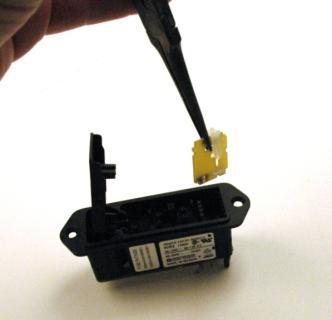
21 head screwdriver, as indicated in Figure 2. Insert the screwdriver into both slots in turn until the panel door pops open. The panel door can then be fully-opened, as indicated in Figure 3, by lifting the door at the far end (end furthest away from the 3-pin socket) and allowing the door to hinge as shown. Step 2: Use pointed pliers to remove the printed circuit board (PCB) as shown in Figures 4 and 5. In the current example, the clear plastic guide attached to the PCB points down to the 120V label on the PCB, as shown in Figure 6. Step 3: Rotate the clear plastic guide, as shown in Figure 7, until the guide points down to the 240V label, as shown in Figure 8 Step 4: Re-install the PCB, as shown in Figure 9, making sure that the lettering on the PCB faces into the housing and the PCB is firmly seated. In this example, once the panel door is firmly closed, the plastic indicator should now occupy the 240V setting hole, as shown in Figure 10. Replacing the fuses: Step 1: Gently pry open the panel door using a small flat head screwdriver, as indicated in Figure 11. Insert the screwdriver into both slots in turn until the panel door pops open. The panel door can then be fully-opened by lifting the door at the far end (end furthest away from the 3-pin socket) and allowing the door to hinge. Step 2: Using the same small flat head screwdriver, remove 21
22 the fuse holder from the power entry module by inserting the screwdriver into one of the two rectangular holes in the fuse holder, as shown in Figure 12, and lifting out the fuse holder with an upward movement of the screwdriver. Step 3: Turn the fuse holder upside down to reveal the set of two fuses, as shown in Figure 13, and replace the fuses as necessary (be careful not to break the retaining posts). The fuses are 5mmx20mm, 250V/2A, fast-acting fuses, and these fuses protect the unit regardless of the input voltage setting (120V or 230V) Note: Replacement fuses must have these same specifications. Step 4: After replacing the fuses, re-install the fuse holder. Note: Make sure that the fuses are downward positioned so that the contact pins located at the bottom of the housing make contact with the fuse terminals the fuses should not be visible after re-installation of the fuse holder. Step 5: Close the hinged panel door and make sure that the door is firmly seated. 22


23 Figure 1 Figure 2 Figure 3 23


24 Figure 4 Figure 5 Figure 6 24


25 Figure 7 Figure 8 Figure 9 25


26 Replacing the Fuses: Figure 10 Figure 11 Figure 12 26

27 Figure 13 27
Model JR-2 Current Interrupter
 Model JR-2 Current Interrupter Operating Manual (Revised August 19, 2011) Catalog # 12830 11640 US Hwy 1, Sebastian FL 32958 Tel: 772-794-9448 ~ Fax: 772-589-9072 E-mail: sales@mcmiller.com ~ Web Site:
Model HPX60 Series Automatic Battery Charger User s Manual Rev. 1.0 October 17, 2006
 B R A N D Model HPX60 Series Automatic Battery Charger User s Manual Rev. 1.0 October 17, 2006 For Sales, Support and Service phone: 407-331-4793 fax: 407-331-4708 website: www.xenotronix.com email: information@xenotronix.com
18VDC ESB6 Series Cordless Screwdrivers Operation Manual
 18VDC ESB6 Series Cordless Screwdrivers Screwdriver Models : ESB6-8, ESB6-12, ESB6-15, ESB6-22 CAUTION - Please read, understand, and follow all operating and safety instructions in this manual before
Electrometer NiCad Battery Replacement
 Electrometer NiCad Battery Replacement Table of Contents NOTE: Although this manual is provided by Standard Imaging as a reference, battery replacement by anyone other than a trained Standard Imaging employee
Model NTX7 Series Automatic Battery Charger User s Manual Rev. 1.0 October 17, 2006
 B R A N D Model NTX7 Series Automatic Battery Charger User s Manual Rev. 1.0 October 17, 2006 For Sales, Support and Service phone: 407-331-4793 fax: 407-331-4708 website: www.xenotronix.com email: information@xenotronix.com
QSSE, QSSEX INDUSTRIAL Battery Chargers
 C O R P O R A T IO N O P E R A T I N G I N S T R U C T I O N S QSSE, QSSEX INDUSTRIAL Battery Chargers INTRODUCTION The QSE line are electronically controlled float chargers. The batteries are brought
CAPACITOR ACTUATED PORTABLE STARTER CAPS USER GUIDE. INST048 Doc 3.01
 CAPACITOR ACTUATED PORTABLE STARTER CAPS USER GUIDE INST048 Doc 3.01 CONTENTS General Information...2 Charts...3 Before First Use...4 Safety Requirements...5 What to Expect from the CAPS...5 CAPS Diagram...6
OBE, OBEXU, ON BOARD Battery Chargers
 C O R P O R A T IO N O P E R A T I N G I N S T R U C T I O N S OBE, OBEXU, ON BOARD Battery Chargers INTRODUCTION: These chargers are designed for the permanent installation on battery powered vehicles
OPERATIONAL MANUAL EMBC-8025 INTELLIGENT BATTERY CHARGER. Version 1.5
 OPERATIONAL MANUAL EMBC-8025 INTELLIGENT BATTERY CHARGER Version 1.5 1 Product Overview EMBC-8025 is an intelligent switching mode battery charger with float maintenance. It is designed to offer maximum
Installation and Operations Manual
 Installation and Operations Manual SEI 150/48-SEL-XXX DC-UPS SEI Incorporated 5115 Pegasus Court, Suite Q Frederick, Md 21704 Phone 301-694-9601 Fax 301-694-9608 Email Info@seipower.com Web http://www.seipower.com
LC BATTERY CHARGER OPERATION & MAINTENANCE GUIDE
 LC BATTERY CHARGER OPERATION & MAINTENANCE GUIDE SENS part number: 101194 Document revision: D DCN number: 105128 Date: 3/23/2006 1840 Industrial Circle Longmont, CO 80501 Fax: 303-678-7504 Tel: 303-678-7500
DC to DC Step Up Converter Model: VTC305
 DC to DC Step Up Converter Model: VTC305 Owner's Manual Please read this manual before operating your converter INTRODUCTION Step up a 12 VDC battery to between 13.5 and 17.0 or 24.0 and 27.5 VDC in 0.5
i n s t r u c t i o n m a n u a l
 i n s t r u c t i o n m a n u a l 8006 Six-Station AC Timer Residential/Light Commercial Independent Program Irrigation Controllers Installation, Programming and Operating Instructions Features Operates
18VDC ESB6-X Series Cordless Screwdrivers Operation Manual
 18VDC ESB6-X Series Cordless Screwdrivers Screwdriver Models : ESB6-X3.5, ESB6-X3.5F, ESB6-X5F ESB6-X6, ESB6-X9, ESB6-X12 CAUTION - Please read, understand, and follow all operating and safety instructions
ST-70 CONTROL OPERATING MANUAL REVISION DATE: PART#:
 ST-70 CONTROL OPERATING MANUAL REVISION DATE: 05-15-07 PART#: 98-0002-09 SERVICE & CUSTOMER INFORMATION CUSTOMER MUST HAVE PART NUMBER WHEN ORDERING ITEMS THROUGH THE SERVICE DEPARTMENT. IF FURTHER HELP
RK Standby Battery Operator s Manual
 49-8104RK Standby Battery Operator s Manual Part Number: 71-0118RK Revision: C Released: 8/4/17 www.rkiinstruments.com Product Warranty RKI Instruments, Inc. warrants gas alarm equipment sold by us to
CBC-802 Plug-In Clutch/Brake Control with Solid State Switching
 DIST. AUTORIZADO Plug-In Clutch/Brake Control with Solid State Switching P-29-5 19-0409 Service & Installation Instructions An Altra Industrial Motion Company DIST. AUTORIZADO Brake (Red) and clutch (Green)
Superchips Model 2704 MAX MicroTuner GM Trucks with 6.6L Duramax Diesel Engines Vehicle Programming Instructions
 Page 1 of 12 Form 0137D 11/30/2004 Superchips Inc. Superchips Model 2704 MAX MicroTuner 2004-2005 GM Trucks with 6.6L Duramax Diesel Engines Vehicle Programming Instructions PLEASE READ THIS ENTIRE INSTRUCTION
1014-SCR WARRANTY AND DISCLAIMER Fillmore Street Davenport, Ia
 2036 Fillmore Street Davenport, Ia. 52804 563-324-1046 www.racedigitaldelay.com 1014-SCR WARRANTY AND DISCLAIMER DIGITAL DELAY INC. WARRANTS THE PRODUCTS IT MANUFACTURES AGAINST DEFECTS IN MATERIALS AND
Silvertel. Ag Features. Multi-Stage Charging. Battery Reversal Protection. Reduced Power Consumption. Wide DC or AC Input Voltage Range
 Silvertel V1.3 October 2009 Datasheet Intelligent Pb 1 Features Multi-Stage Charging Battery Reversal Protection Reduced Power Consumption Wide DC or AC Input Voltage Range High Efficiency DC-DC Converter
OPERATION & MAINTENANCE
 OPERATION & MAINTENANCE VaxiCool Mobile Refrigerator/Freezer An Advanced Technology Vaccine Storage & Transport System Model VXC-2 2900 Dryden Road Dayton, Ohio 45439 U.S.A. Telephone: (937) 312-0114 Fax:
INSTALLATION & OWNER'S MANUAL
 INSTALLATION & OWNER'S MANUAL THE EAGLE POWER I BATTERY BACK UP PHONE (818) 764-6690 / TOLL FREE (800) 708-8848 PRE INSTALLATION INSTRUCTIONS BEFORE PROCEEDING WITH INSTALLATION READ THIS MANUAL THOROUGHLY
ODY-05-2 VOLTMETER FOR REMOTE MONITORING
 ODY-05-2 VOLTMETER FOR REMOTE MONITORING Introduction: The Odyssey gauge series from Dakota Digital, Inc. incorporates the reliability and quality of our standard gauges, along with several unique features
OPERATING MANUAL Digital Diesel Control Remote control panel for WhisperPower generator sets
 Art. nr. 40200261 OPERATING MANUAL Digital Diesel Control Remote control panel for WhisperPower generator sets WHISPERPOWER BV Kelvinlaan 82 9207 JB Drachten Netherlands Tel.: +31-512-571550 Fax.: +31-512-571599
CONTACT TACHOMETER User s ManUal CT6235B
 CONTACT TACHOMETER User s ManUal CT6235B Please read this manual carefully and thoroughly before using this product. TABLE OF CONTENTS Introduction......................... 3 Key Features........................
ODY-19-1 AIR PRESSURE GAUGE
 ODY-19-1 AIR PRESSURE GAUGE Introduction: The Odyssey gauge series from Dakota Digital, Inc. incorporates the reliability and quality of our standard gauges, along with several unique features and easy
MODEL A96 SERIES. 130Vdc Switchmode Utility Rectifier / Battery Charger. Used with LaMarche Power Cage ECN/DATE
 MODEL A96 SERIES 130Vdc Switchmode Utility Rectifier / Battery Charger Used with LaMarche Power Cage CPN112138 ECN/DATE ISSUE DATE: ECN 17010-12/05 106 BRADROCK DRIVE DES PLAINES, IL. 60018-1967 (847)
series USER MANUAL
 888 534-5994 4000 series USER MANUAL Contents Here s all the information you need for setting and operating your new Lathem time recorder. Service information is also included in this manual, in case any
600 Amp Battery Jumper with Air Compressor
 Item #2509 600 Amp Battery Jumper with Air Compressor User s manual- Read these instructions before using the unit Features Front LED Worklight Worklight Switch USB Power Ports and on/off Switch 12V DC
CRD610 Automatic Fitting Inserter
 CRD610 Automatic Fitting Inserter OPERATIONS MANUAL VERSION 1.2 LAST EDITED 12.12.2018 cleanroomdevices.com 1 Table of Contents Title Page. 1 Table of Contents...2 1.0 General Product & Safety Information....3
model ps600 Address all communications and shipments to: FEDERAL SIGNAL CORPORATION
 MODEL: PS600 HZ: 60 A model ps600 installation and service manual for federal model ps600 FEDERAL SIGNAL CORPORATION POWER SUPPLY VOLTS: SERIES: 120VAC FEDERAL SIGNAL CORPORATION UNIVERSITY PARK, IL. U.S.A.
OBAE, OBAEXU, ON BOARD Battery Chargers
 C O R P O R A T IO N O P E R A T I N G I N S T R U C T I O N S OBAE, OBAEXU, ON BOARD Battery Chargers INTRODUCTION: The OBAE line of chargers are designed for the permanent installation on battery powered
IV. PROOF OF PURCHASE: A warranty claim must be accompanied by proof of the date of purchase.
 PD9100 / 9200 SERIES POWER CONVERTER OWNERS MANUAL PROGRESSIVE DYNAMICS, INC. POWER CONVERTER LIMITED WARRANTY I. LIMITED WARRANTY: Progressive Dynamics, Inc. warrants its power converter to be free from
User s Manual. Automatic Switch-Mode Battery Charger
 User s Manual Automatic Switch-Mode Battery Charger IMPORTANT Read, understand, and follow these safety rules and operating instructions before using this battery charger. Only authorized and trained service
CONTENTS TABLE OF CONTENTS... 1 INTRODUCTION... 2 SEC 1 - SPECIFICATIONS... 3 SEC 2 - DESCRIPTION... 5 SEC 3 - OPERATING INSTRUCTIONS...
 CONTENTS SUBJECT PAGE TABLE OF CONTENTS... 1 INTRODUCTION... 2 SEC 1 - SPECIFICATIONS... 3 SEC 2 - DESCRIPTION... 5 SEC 3 - OPERATING INSTRUCTIONS... 8 SEC 4 - BATTERY CHARGING NOTES... 9 SEC 5 - VERIFICATION
User Manual. T6 Tachometer. Online: Telephone: P.O. Box St. Petersburg, Florida 33736
 User Manual T6 Tachometer Online: www.phareselectronics.com Telephone: 727-623-0894 P.O. Box 67251 St. Petersburg, Florida 33736 Table of Contents Overview... 1 Description... 1 Wiring... 1 T6 Tachometer
BRAVO Inverter/Battery Charger. Table of Contents
 BRAVO 1050 Inverter/Battery Charger Table of Contents Introduction... 2 General Description... 2 Specifications... 3 Installation: Hardwire Units... 4 Operation: Hardwire Units... 5-6 Installation: GFCI
BBT-205. For 12-volt automotive starting batteries and starting/charging systems INSTRUCTION MANUAL
 For 12-volt automotive starting batteries and starting/charging systems INSTRUCTION MANUAL Blank page Contents Registering Your tester... 5 Caution... 6 Capabilities... 6 Display and Keypad... 6 Preparations
DIESEL Engine Fire Pump Controllers Features
 1-1 Printer / Recorder The industrial grade thermal printer is housed in a rugged steel enclosure within the controller. The on/off switch, feed and reset buttons are front accessible. A bi-color status
Advanced Calibration Designs, Inc. Release II
 Advanced Calibration Designs, Inc. Release II www.goacd.com WARNING: This instrument generates test gas for toxic gas detectors. The instruction manual should be read and understood prior to operation
RK Standby Battery Operator s Manual
 49-8103RK Standby Battery Operator s Manual Part Number: 71-0117RK Revision: 0 Released: 8/18/08 www.rkiinstruments.com Product Warranty RKI Instruments, Inc., warrants gas alarm equipment sold by us to
Series. idrive 300. Installation and User s Guide INTELLIGENT ENVIRONMENTAL CONTROL. March 2014 v1.1 Edition Copyright 2014 Corporation
 idrive 300 Series INTELLIGENT ENVIRONMENTAL CONTROL Installation and User s Guide March 2014 v1.1 Edition Copyright 2014 Corporation Table of Contents Introduction... 1 Customer Service... 2 Contact Us...
User manual MTS-32. QUI-1013 Version 1.5 January
 Version 1.5 January 2015 User manual MTS-32 Page 2 Contents 1. Introduction... 3 2. Principles of operation... 3 2.1 Principles of MTS-32 ventilation... 3 2.2 Principles of sorbent tube sample collection
Model 2008 I Battery Operated Irrigation Timer with 3/4 in. Anti-Siphon Valve
 i n s t r u c t i o n m a n u a l Model 2008 I Battery Operated Irrigation Timer with 3/4 in. Anti-Siphon Valve Features Weekly or cyclical programming 4 start times per day in weekly program Irrigation
SRC. An Outdoor Reset Control for Sub-Atmosphere Steam Systems OUTDOOR TEMPERATURE
 SRC STEAM RESET CONTROL An Outdoor Reset Control for Sub-Atmosphere Steam Systems Heat-Timer s theory of steam reset heating is as follows: Pulse the valve open to a limited valve position, very slowly
Generator Start Control Module
 Generator Start Control Module Part# GSCM-mini-i ATKINSON ELECTRONICS, INC. 14 West Vine Street Murray, Utah 84107 Contact cbdsales@atkinsonel.com for the proper hookup diagram. Please include the generator
USER S MANUAL GPC SERIES LOW VOLTAGE DISCONNECT. Galley Power LLC.
 USER S MANUAL GPC SERIES LOW VOLTAGE DISCONNECT Galley Power LLC www.galleypower.com Table of Contents Safety Notice... 3 Disclaimer... 3 Safety Instructions... 4 1. Introduction... 5 1.1 Features and
Digital Mobile Charge Advanced Electronic In-Transit 4-Stage Battery to Battery Charger
 Digital Mobile Charge Advanced Electronic In-Transit 4-Stage Battery to Battery Charger Owner s Manual and Installation Guide Model Part Number Description Digital Mobile Charge 05502 Advanced In-Transit
BoostPak2 Instruction Manual
 Sheet 1 of 8 BoostPak2 Instruction Manual MobilePower, LLC. Bluffton, SC 29910 www. Mobilepower-us.com Office: (800) 708-8550 support@mobilepower-us.com customerservice@mobilepower-us.com Sheet 2 of 8
O P E R A T I N G I N S T R U C T I O N S
 O P E R A T I N G I N S T R U C T I O N S Select-A-Charge Battery Chargers models: SCP, SCPX, SCS, SCSX, SCX For Industrial Use: Designed for gel, wet cell, AGM, and Lithium Ion batteries (Lithium ion
POWER TROLLEY 8 INSTRUCTION MANUAL POWER TROLLEY 8. Model: SINE Instruction Manual for: Self-Contained Sinewave Mobile Power Backup System
 POWER TROLLEY 8 Model: SINE 1548 Instruction Manual for: Self-Contained Sinewave Mobile Power Backup System Version 07 CONTENTS Page 1. INTRODUCTION... 1 2. USING THE POWER TROLLEY.... 2 3. BATTERY BACKUP
Installation and Operation Guide
 Bus-Scan CR2 RF Installation and Operation Guide All Content and Information are Copyright 2018 Robotics Technologies, Inc. Features and Information are subject to change without notice. All Rights Reserved.
AC Irrigation and Propagation Controllers I Four Station, 5006-I and 5006-IP Six Station
 AC Irrigation and Propagation Controllers 5004-I Four Station, 5006-I and 5006-IP Six Station I N S T R U C T I O N M A N U A L Table of contents Introduction 1 1. Specifications 1 2. Controller Mounting
Generator Start Control Module
 Generator Start Control Module Part# GSCM Rev C. Code Version: 5.13 ATKINSON ELECTRONICS, INC. 14 West Vine Street Murray, Utah 84107 Table of Contents Operations... 3 Specifications... 3 GSCM Wiring Diagram...
POWERLINE 2000 Energy Management System TM
 Display Panel TM The PowerLine 00 EMS is a specialized power distribution and energy management system intended to be used in recreational vehicles. The Control Module is housed in the standard main distribution
ALEX-TRONIX SMART CLOCK TM. BATTERY POWERED TEMPERATURE BUDGETING CONTROLLER MANUAL Patent Pending A DIVISION OF GNA INDUSTRIES, INC.
 ALEX-TRONIX A DIVISION OF GNA INDUSTRIES, INC. SMART CLOCK TM BATTERY POWERED TEMPERATURE BUDGETING CONTROLLER MANUAL Patent Pending M A N U A L INTRODUCTION The Smart Clock is a non-solar battery powered
Activator 282 Aircraft Battery Maintenance Charger Operator Manual
 Activator 282 Aircraft Battery Maintenance Charger Operator Manual Revision 2.1a February 2013 This Operator Manual applies to the Activator 282 with a Liquid Crystal Display starting with Serial Number
1014-CTC WARRANTY AND DISCLAIMER
 2036 Fillmore Street Davenport, Ia. 52804 563-324-1046 www.racedigitaldelay.com 1014-CTC WARRANTY AND DISCLAIMER DIGITAL DELAY INC. WARRANTS THE PRODUCTS IT MANUFACTURES AGAINST DEFECTS IN MATERIALS AND
QuickBoost Instruction Manual
 Sheet 1 of 12 QuickBoost Instruction Manual MobilePower, LLC. Bluffton, SC 29910 www. Mobilepower-us.com Office: (800) 708-8550 support@mobilepower-us.com customerservice@mobilepower-us.com Sheet 2 of
MDX-300 Series. For 12-volt automotive starting batteries and starting/charging systems INSTRUCTION MANUAL
 For 12-volt automotive starting batteries and starting/charging systems INSTRUCTION MANUAL Blank page Contents Caution... 4 Capabilities... 4 Display and Keypad... 4 Preparations Before the Test... 6 Connecting
This document describes:
 Thank you for purchasing this product from ERM. We appreciate your interest in our unique product line as we try to offer our customers an alternative to today s traditional products. This programmable
QPET, QPETXU Battery Chargers
 C O R P O R A T IO N O P E R A T I N G I N S T R U C T I O N S QPET, QPETXU Battery Chargers INTRODUCTION: The QPET line of chargers are designed for general purpose deep cycle batteries. They are an electronically
ODYR-19-5 & SLX-19-5 DUAL, TRIPLE, or QUAD AIR PRESSURE GAUGE
 ODYR-19-5 & SLX-19-5 DUAL, TRIPLE, or QUAD AIR PRESSURE GAUGE Features: All bag pressure readings displayed at once on a 2-line display. Optional storage tank pressure readout. A warning feature that flashes
COLT CELL BATTERY CHARGER Installation and Operating Instructions
 COLT CELL BATTERY CHARGER Installation and Operating Instructions INSTALLATION All COLT chargers are for indoor use only. All COLT chargers are designed for installation into the battery tray. Charging
Superchips Model 1725 MAX MicroTuner 4.6L Ford Automobiles Vehicle Programming Instructions
 Page 1 of 16 Form 0130K 06/06/2004 Superchips Model 1725 MAX MicroTuner 4.6L Ford Automobiles Vehicle Programming Instructions PLEASE READ THIS ENTIRE INSTRUCTION SHEET BEFORE YOU PROCEED This product
MODEL MCL /8 SPEEDOMETER/TACHOMETER for 2004 up
 MODEL MCL-3204 3-3/8 SPEEDOMETER/TACHOMETER for 2004 up IMPORTANT NOTE! This gauge has an odometer preset option that is only available one time in the first 100 miles (160km) of operation. See Odometer
Operator's Manual. Storage System. Ultrasound Probe Cabinet. Manufactured by:
 Storage System Ultrasound Probe Cabinet Operator's Manual Manufactured by: CIVCO Medical Solutions 102 First Street South Kalona, IA 52247 USA 319.248.6757 / 800.445.6741 WWW.CIVCO.COM Copyright 2018 All
DC to AC Power Inverters
 Manufacturer of Dimensions TM Inverters 4467 White Bear Parkway St. Paul, MN 55110 Phone: 651-653-7000 Fax: 651-653-7600 E-mail: inverterinfo@sensata.com Web: www.dimensions.sensata.com ISO 9001:2000 Certified
CBC-300 Series & CBC-300C Series Dual Channel Adjust Clutch/Brake Controls
 CBC-300 Series & CBC-300C Series Dual Channel Adjust Clutch/Brake Controls P-269-89-0408 Installation Installation & Operating Instructions Contents Introduction........................... 2 Specifications.........................
DC to AC Power Inverters
 Manufacturer of Dimensions TM Inverters 4467 White Bear Parkway St. Paul, MN 55110 Phone: 651-653-7000 Fax: 651-653-7600 E-mail: inverterinfo@sensata.com Web: www.dimensions.sensata.com 121114C OWNERS
installation and operating instructions for the following xtreme Battery chargers:
 installation and operating instructions for the following xtreme Battery chargers: Model Name No. of Banks Amps Per Bank Battery System Dual Pro SE Xtreme Dual Pro Xtreme Three Bank SE Xtreme Three Bank
A2P Single Phase Automatic Industrial Battery Charger
 A2P Single Phase Automatic Industrial Battery Charger Featuring 205B Konrad Cres., Markham, ON, L3R 8T9 www.chargers.ca Building Canada s toughest battery chargers for over a century. Congratulations on
Installation and Operating Instructions (for chargers shown below)
") Installation and Operating Instructions (for chargers shown below) For additional information please call our Technical Support Group 800.742.2740 PRO CHARGING SYSTEMS, LLC 1551 Heil Quaker Boulevard,
Installation and Operating Instructions (for chargers shown below) For additional information please call our Technical Support Group 800.742.2740 PRO CHARGING SYSTEMS, LLC 1551 Heil Quaker Boulevard,
Components. Options Accessory Harness USB Charger. Quick Connector. Hook & Loop / Cable-ties. RFID Antenna. Module. Main Harness.
 SRX SERIES Table of Contents - Components - Planning The Install - Mounting - Switched Power - Attach Accessory Harness - Plug In Module - Back-Up Battery - Remote Encoding - 2-Way RFID Remote User Instructions
MODEL MCL-3212 SPEEDOMETER/TACHOMETER for 2012 up Dyna and Softail with 4 gauge
 MODEL MCL-3212 SPEEDOMETER/TACHOMETER for 2012 up Dyna and Softail with 4 gauge IMPORTANT NOTE! This gauge has an odometer preset option that is only available one time in the first 100 miles (160km) of
CRD600 Automatic Fitting Inserter
 CRD600 Automatic Fitting Inserter OPERATIONS MANUAL VERSION 2.3 LAST EDITED 12.07.2018 cleanroomdevices.com 1 Table of Contents Title Page.. 1 Table of Contents. 2 1.0 General Product & Safety Information...3
SOLAR BOLT CHARGING SYSTEM INSTALLATION GUIDE
 CHARGING SYSTEM Doc 1.00 INST052 1 SOLAR BOLT CHARGING SYSTEM CONTENTS General Information... 2 Solar Panel Installation... 3 Solar Bolt Main Harness and Indicate Installation... 4 Cable Routing... 9 Solar
ALFA-Club. Owners Manual Rev 4.0, August Small Systems Specialists 201 N. Lobb Ave. Pen Argyl, PA Memory Checkpoint Clock
 ALFA-Club Memory Checkpoint Clock Dual Odometer/Clock Owners Manual Rev 4.0, August 2018 Small Systems Specialists 201 N. Lobb Ave. Pen Argyl, PA 18072 609-301-0541 ALFA@Rally.cc On the web at www.rally.cc
FR1118- P10. User s Manual
 FR1118- P10 User s Manual WARNING Read carefully and understand all INSTRUCTIONS before operating. Failure to follow the safety rules and other basic safety precautions may result in serious personal injury.
Generator Start Control Module
 Generator Start Control Module Part# GSCM-mini-o ATKINSON ELECTRONICS, INC. 14 West Vine Street Murray, Utah 84107 Contact cbdsales@atkinsonel.com for the proper hookup diagram. Please include the generator
BATTERY & STARTER ANALYSER (BSA-12) User Manual
 User Manual") BATTERY & STARTER ANALYSER (BSA-12) User Manual Introduction BSA-12 Battery Starter Analyser does not carry internal batteries but is powered up from external DC source ranging from 9V to 15V DC. It is
BATTERY & STARTER ANALYSER (BSA-12) User Manual Introduction BSA-12 Battery Starter Analyser does not carry internal batteries but is powered up from external DC source ranging from 9V to 15V DC. It is
innovations in battery charging
 innovations in battery charging AutomaticBatteryCharger forsealed or Valve Regulated Lead-Acid Batteries Model HPX-60 Series OperatingInstructions WARNING CONCERNING THE REMOVAL OF COVER: CAUTION: TO PREVENT
Silvertel. Ag Features. Multi-Stage Charging. Battery Reversal Protection. Reduced Power Consumption. Wide DC or AC Input Voltage Range
 Silvertel V1.1 October 2012 Pb 1 Features Multi-Stage Charging Battery Reversal Protection Reduced Power Consumption Wide DC or AC Input Voltage Range High Efficiency DC-DC Converter Programmable Charge
# Traction Control Window Switch
 1 INSTRUCTIONS # 82085 Traction Control Window Switch Thank you for choosing products; we are proud to be your manufacturer of choice. Please read this instruction sheet carefully before beginning installation,
Dimensions 12/800N 12/1200N D. DC to AC Power Inverters. OWNERS MANUAL for Models: OWNERS MANUAL April ISO 9001:2000 Certified Company
 Manufacturer of Dimensions Inverters 4467 White Bear Parkway St. Paul, MN 55110 Phone: 651-653-7000 Fax: 651-653-7600 E-mail: inverterinfo@sensata.com Web: www.dimensions.sensata.com OWNERS MANUAL April
Installation and Operating Instructions (for chargers shown below)
") Installation and Operating Instructions (for chargers shown below) For additional information please call our Technical Support Group 800.742.2740 PRO CHARGING SYSTEMS, LLC 1551 Heil Quaker Boulevard,
Installation and Operating Instructions (for chargers shown below) For additional information please call our Technical Support Group 800.742.2740 PRO CHARGING SYSTEMS, LLC 1551 Heil Quaker Boulevard,
BATTERY BOOSTER/CHARGER MODEL NO: DIGICAR 600
 BATTERY BOOSTER/CHARGER MODEL NO: DIGICAR 600 PART NO: 6261200 OPERATION & MAINTENANCE INSTRUCTIONS LS0815 INTRODUCTION Thank you for purchasing this CLARKE Battery booster / charger which is suitable
Manual Installation & Operation
 Manual Installation & Operation Model: NCxxLxx 12A or 30A Solid State Solar Charging Regulator and 12A Load Controller. 231 Patent #: 5,642,030 Applies Page 1 Warnings When Installing, connect grounds,
Item no Smart AC 200 USB. User s Manual
 R Item no. 2402 Smart AC 200 USB User s Manual Smart AC 200 Watt with USB by Wagan Tech User s Manual Read before using this equipment Thank you for purchasing Smart AC 200 Watt with USB by Wagan Tech.
REVISION HISTORY REVISION HISTORY
 FILTER CONTROLLER REVISION HISTORY Filter Flush Controller forms part of the Netafim range of filtration controllers all designed to make filteration more reliable and economical.. Contact any of the Netafim
Safety, Installation And Operating Instructions For The Following Battery Charger Models: i2412, i3612, i4809, i2425, i3625, and i4818
 Safety, Installation And Operating Instructions For The Following Battery Charger Models: i2412, i3612, i4809, i2425, i3625, and i4818 IMPORTANT NOTICE: Please save and read these safety, operating and
NANOPAC-300 & 500 Power Supply. Instruction manual NANOPAC-300 & NANOPAC-500
 NANOPAC-300 & 500 Power Supply Instruction manual NANOPAC-300 & NANOPAC-500 Version 01C Feb 5th, 2014 1 Packing list NANOPAC-300 or 500-1x NANOPAC-300 Power Supply or NANOPAC-500-1x Power Cord - 1x Instruction
NoMAX 900 SERIES. Instruction SWITCHED CAPACITOR CONTROLS
 Instruction Manual NoMAX 900 SERIES SWITCHED CAPACITOR CONTROLS NoMax 900T NoMax 950 NoMax 900 HD ELECTRIC COMPANY 1 4 7 5 L A K E S I D E D R I V E WA U K E G A N, I L L I N O I S 6 0 0 8 5 U.S. A. PHONE
ValveMate 7000 Controller Operating Manual
 A NORDSON COMPANY ValveMate 7000 Controller Operating Manual Steady Test Clear Time Set Fast Slow POWER RUN SETUP CYCLE A NORDSON COMPANY VALVEMATE 7000 Run Setup Purge Program Fast Slow Time Set Pressure
CBC-802 Plug-In Clutch/Brake Control with Solid State Switching
 CBC-02 Plug-In Clutch/Brake Control with Solid State Switching P-2104-WE 19-054 Service & Installation Instructions An Altra Industrial Motion Company Brake (Red) and clutch (Green) indicator lights When
INSTRUCTION MANUAL. Rotary Unidirectional Piezoelectric Motor Evaluation Kit. (Model: UPM-28) Made in USA
 Made in USA") www.dtimotors.com INSTRUCTION MANUAL Rotary Unidirectional Piezoelectric Motor Evaluation Kit (Model: UPM-28) Made in USA Rev. 6/2/2017 Table of Contents 1.0 Introduction... 2 2.0 Properties... 3 3.0 Unpacking
www.dtimotors.com INSTRUCTION MANUAL Rotary Unidirectional Piezoelectric Motor Evaluation Kit (Model: UPM-28) Made in USA Rev. 6/2/2017 Table of Contents 1.0 Introduction... 2 2.0 Properties... 3 3.0 Unpacking
PHOTO VOLTAIC CHARGE MODULE MULTI POINT TRACKING
 FEATURES Multi Point Tracking (MPT)/ Pulse Width Modulation (PWM) is a six stage solar charge controller. Drop-in PWM replacement for the PVCM-25D two stage solar charge controller. Works with the PVDM4-LC,
The function of this Dynamic Active Probe has divided into three preferences on the screen main Menus:
 1.0 Introduction: This probe is designed to provide an additional help to automotive technicians in trouble shooting of electrical circuits problems in the car. Apart from using the normal multi tester,
Power Distribution System User s Manual. Model: PDS-100
 Power Distribution System User s Manual Model: PDS-0 Section Page Product Overview... 1 I) General Information... 2 II) Important Safety Information... 2 III) Installation... 3 A) Materials Provided...
HLY-1111 HEAD TEMPERATURE GAUGE
 HLY-1111 HEAD TEMPERATURE GAUGE Introduction: The Odyssey gauge series from Dakota Digital, Inc. incorporates the reliability and quality of our standard gauges, along with several unique features and