WARNINGS. Maintenance must be properly done to avoid serious injury risks. Improper maintenance can result in injury or property damage.
|
|
|
- Edward Barber
- 6 years ago
- Views:
Transcription


1
2
3 Foreword This service manual has been elaborated to help service personnel to provide efficient and correct service and maintenance on the TM31 (formerly called DKS 32) compressor (for HFC-134a) for automotive air conditioning. This manual includes the operation specifications, procedures for disassembly, reassembly, and inspection of the compressor. The contents of this manual, including illustrations, drawings and specifications were the latest available at the time of printing. Valeo Japan reserves the right to make changes in specifications and procedures at any time without notice. VALEO JAPAN CO., LTD. WARNINGS The following warning signs are used in this service manual. These are extremely important to ensure safe operation and to prevent body injuries and property damage. They must be fully understood before starting the air conditioner maintenance. WARNING! CAUTION! Maintenance must be properly done to avoid serious injury risks. Improper maintenance can result in injury or property damage. MEANING OF MARKS The following marks are used in this service manual to facilitate correct air conditioner maintenance. Advice Note Procedures necessary to ensure the best air conditioner maintenance. Information to optimize the air conditioner maintenance
4 Contents 1- Product description Operation precautions Handling instructions Maintenance precautions...14 Work area...14 Refrigerant handling...14 Compressor handling...15 Compressor removal...15 Oil return operation...16 Oil handling...16 Oil contamination...17 Oil check...17 Replacement of components...18 Running-in operation...19 Compressor running-in...19 Magnetic clutch running-in...19 Leak test...20 Refrigerant charging...20 Storing a repaired compressor Troubleshooting Compressor troubleshooting...21 Compressor troubleshooting tree...21 A/C cycle diagnosis by gauge pressure Tightening torques Service procedures - Magnetic clutch Service procedures - Shaft seal assembly Service procedures - Cylinder heads Service tools Service parts
5
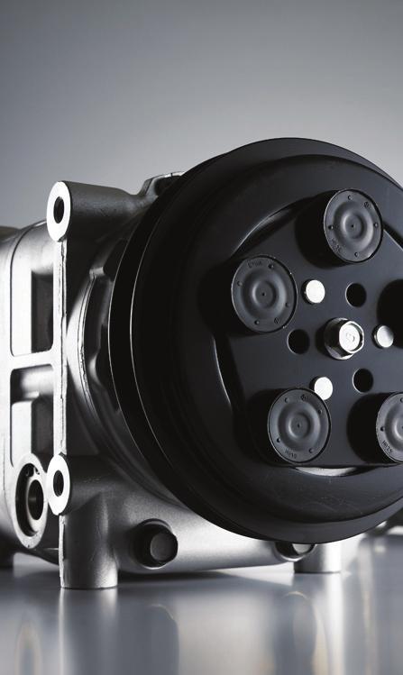
6 1- Product description - Magnetic clutch Specifications* TYPE RATED VOLTAGE POWER CONSUMPTION STATIC TORQUE DIRECTION OF ROTATION WEIGHT V-BELT TYPE Electromagnetic single-plate dry clutch 24V DC or 12 V DC 48 W maximum 78 N m {8.0 kgf m, 58 lbf ft} Clockwise, viewed from clutch Approx 4.5 kg {10 lb} V-groove (A or B) or V-ribbed (PK) The above specifications may vary with the compressor
7 1- Product description - Performance The performance data below were measured under the following conditions: Compressor speed: 1450 rpm Suction gas temperature: 20 o C Valeo TM31 performance data (R134a) Cond temp ( o C ) Conditions Pd (MPaG) Evap temp ( o C ) Cooling capacity Q (kw) & Power consumption P (kw) Ps (MPaG) P (kw) Q (kw) P (kw) Q (kw) P (kw) Q (kw) Valeo TM31 conversion factors Power consumption data at different rotation speed can be approximated with the conversion factors below. 3.0 P Conversion factors Q Compressor speed (rpm) Lip-seal type shaft seal The compressor has a lip-seal type shaft seal. This type of shaft seal greatly improves the sealing of the compressor to increase its performance and durability
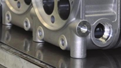
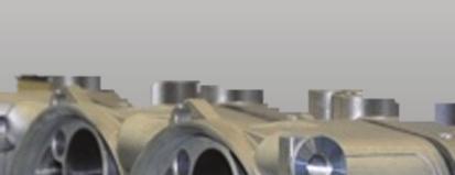
8 1- Product description - Dimensions TM31compressors with magnetic clutch Unit: mm M8x (effective diameter) ~ Other connecting type Approx M10x Approx 244 Approx M8x
9 1- Product description - Exploded view 1. Center bolt 2. Armature assembly 3. Adjusting shim 4. Snapring 5. Pulley assembly 6. Screw 7. Field coil 8. Bolt 9. Washer 10. Front cylinder head 11. Shaft seal assembly 12. Gasket 13. Valve plate assembly 14. Suction valve 15. O-ring 16. Cylinder shaft assembly 17. Oil filler plug 18. O-ring 19. Strainer (option) 20. O-ring 21. Suction valve 22. Valve plate assembly 23. Gasket 24. Gear pump 25. Rear cylinder head - 7 -
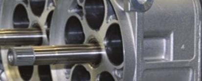
10 1- Product description - Swash plate system Valeo TM31 are 10-cylinder swash plate type compressors. With this type of compressors, the cylinders and pistons are arranged axially along the drive shaft. The pistons operate within the cylinders and are driven by a swash plate to perform suction, compression and discharge. Swash plate system The drive shaft, which is driven by the engine through the magnetic clutch, is equipped with a swash plate. The drive shaft is supported by two radial bearings and two thrust bearings. The swash plate is rotated by the drive shaft, and moves the pistons back and forth. Drive shaft Radial bearing Piston Radial bearing Suction Compression Swash plate Radial bearing Thrust bearing Suction Compression Thrust bearing Piston drive system The pistons in the cylinders are mounted on the swash plate through a drive ball and a shoe disk. Each piston has a compression head at each end. The rotation of the swash plate rotation results in a reciprocating piston movement parallel to the drive shaft. The cylinders, which are arranged at 72 intervals around the drive shaft, are each divided into 2 chambers, providing 5 front and 5 rear bores. As each piston performs suction and compression at either end, the compressor operates as a 10 cylinder compressor. Shoe disk Ball Piston - 8 -
11 1- Product description - Lubrication The compressor is lubricated by a gear pump in the rear cylinder head which is connected to the compressor. Oil flow When the compressor starts operating, the gear pump draws oil from the reservoir and pumps it through an oil passage in the shaft. The oil then flows through ports in the shaft to lubricate the bearings and the shaft seal. The area between the swash plate and the shoe disks is lubricated by the splashing action of the oil flowing through the thrust bearings. Oil also flows through ports in the pistons to lubricate the cylinders and the pistons. Drive shaft Shaft seal Swash plate Radial bearing Gear pump Oil passage Radial bearing Reservoir Thrust bearing Oil passage - 9 -
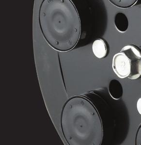
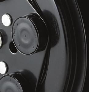
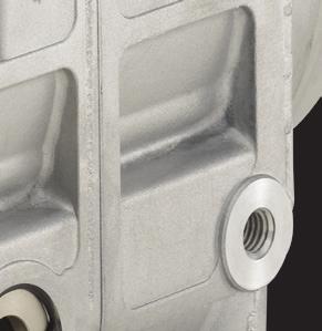
12 1- Product description Caps Compressor 1. The direction of rotation is clockwise as viewed from the clutch side. 2. Each compressor is delivered filled with a specified quantity of compressor oil as described on its label. The total amount of oil your air conditioning system requires is provided by the system designer or supplier. Operation conditions table Item Surrounding temperature Speed Pressure Condition Under 100 C (212 F) Maximum: 7,000 rpm Continuous: 6,000 rpm Maximum: 2.4 MPaG {24.5kgf/cm 2,348 psig} 3. The compressor must be operated under the conditions shown in the operation conditions table shown at the left. CAUTION! The A/C cycle components must be designed so that the pressure in the cycle does not exceed 2.4 MPaG {20 kgf/cm 2, 348 psig} Inclination limit at installation The compressor must be installed on the vehicle within the inclination range shown at the left. 5 Compressor bracket 1. Install the bracket securely on the chassis frame or engine body. As the engine vibrations may be severe, the bracket and mounting bolts must be installed securely. 2. Vibration resistance There must not be any resonance under 250 Hz
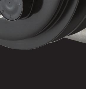
13 1- Product description Magnetic clutch 1. Voltage DC 24 V The terminal voltage of the magnetic clutch must exceed 21 V. DC 12 V The terminal voltage of the magnetic clutch must exceed 10.5 V. 1 mm Magnetic clutch Idle pulley Drive pulley 2. Ratio of magnetic clutch to drive pulley When the compressor is driven from the pulley drive of the vehicle, the magnetic clutch to drive pulley ratio should avoid the range 1: to limit vibration and resonance. Compressor speed must not exceed the specified speed. CAUTION! Pulley ratio is the ratio of the magnetic clutch diameter to the drive pulley diameter. 3. Pulley alignment tolerance is less than 1mm (0.04 in). 4. Pulley groove: V-groove or V-ribbed. 5. The belt tension must be adjusted to the tension specified by the belt maker
14 1- Product description Gas type thermo switch Capillary tube Control switches 1. Thermo switch A thermo switch is necessary. The following specification is recommended. Compressor OFF: Evaporator fin surface temperature of 0 C (32 F) or below. The thermo switch is used to prevent the evaporator from freezing. ON Operation temperature C ( F) DIFF 4 or 3(39 or 37) OFF 0 (32) ON 0.19 {1.9, 27} 1.47 {15, 213} OFF 0.18 {1.8, 26} 2.65 {27, 384} 2. Dual pressure switch A dual pressure switch is necessary. The following specifications are recommended. Compressor OFF High pressure control 2.65 MPaG {27 kgf/cm 2, 384 psig} or higher Low pressure control 0.18 MPaG {1.8 kgf/cm 2, 26 psig} or lower The dual pressure switch controls high and low pressure. High pressure control When abnormally high pressure develops, the compressor is turned OFF to protect the system. Low pressure control When there is insufficient refrigerant in the system, compressor operation is stopped to prevent the compressor from seizing
15 2- Operation precautions 1. During the off season of the air conditioner, operate the compressor for a few minutes once a week. 2. Do not drive through water. Water may damage the magnetic clutch, thus preventing normal operation. 3. Do not allow a compressor that has not been used for a long period to become wet. 4. Always charge the A/C system with the specified quantity of refrigerant. 5. Keep the compressor clear of water projection while cleaning the vehicule
16 3- Handling instructions Maintenance precautions Work area As the components of air conditioners are particularly sensitive to moisture, dirt and rust, always observe the following: Work indoors whenever possible Select a flat ground work area Keep the work area clean Select a work area with adequate ventilation. CAUTION! Refrigerant itself is not harmful, but excessive accumulation in a closed area can cause oxygen deficiency. Keep open flame and inflammables away from the vehicle in which the air conditioner is being installed. (Fire is particularly dangerous during the gas leak inspection following installation) Safety glasses Gloves WARNING! Contact with flame and high temperatures can generate toxic gases. Refrigerant handling WARNING! Direct contact with refrigerant can cause frostbite or blindness. Always wear safety glasses and protective gloves. Do not work with refrigerant close to your face. 1. Do not misidentify refrigerants If an HFC-134a air conditioning system is mistakenly charged with another refrigerant, serious problems such as compressor seizing may occur. Therefore, confirm before charging with refrigerant that the type of air conditioning system is an HFC-134a system
17 3- Handling instructions Do not release refrigerant into the air FILL AUTO 2. Do not release refrigerant into the air Although HFC-134a is not subject to CFC regulations, it can have effect on global warming and so should not be released into the air. When removing refrigerant from the air conditioning system, always use a refrigerant recovery unit made specifically for HFC-134a. Recovery unit Compressor handling Do not strike or unecessarily turn the compressor upside down. If the compressor is knocked over or turned upside down during handling or installation, rotate the armature plate 5 or 6 times to circulate the oil. Otherwise, oil in the cylinder during compressor start-up will cause valve damage and reduce durability. Compressor removal When the compressor is operational 1. Perform the oil return operation (see p.16). 2. Recover the refrigerant from the system using a refrigerant recovery unit. 3. Remove the compressor. 4. Drain the oil from the compressor and close all open connections immediately. 5. Check the oil quantity and the degree of contamination (see p.17). When the compressor is inoperable 1. Recover the refrigerant from the system using a refrigerant recovery unit if the shut-off valves are to be removed with the compressor. 2. Remove the compressor. 3. Drain the oil from the compressor and close all open connections immediately. 4. Check the oil quantity and the degree of contamination (see p.17)
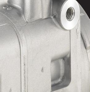
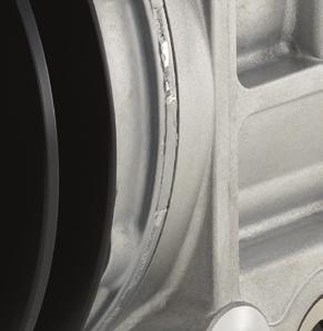
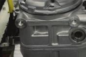
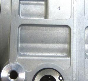
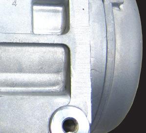
18 自動 自動 3- Handling instructions Oil return operation 強冷 電源 Compressor oil mixed with refrigerant is circulating in the air conditioning system. Perform the oil return operation to return this oil to the compressor before removing components from the system. 1. Open the doors and windows and operate the blower motor at maximum speed. 2. Operate the vehicle engine at idling during at least 20 minutes. Note: The maximum amount of oil cannot be recovered at higher speeds. This operation also requires a warm ambient temperature. Oil handling Oil specification Use only ZXL 100PG PAG (DH-PS). As long as it remains within the range of vision through the sight glass, the oil quantity is sufficient Oil quantity inspection There is no particular need for frequent inspection or replacement, although it is recommended to check operating refrigerent pressures and oil levels at the start of the season. Please replace the refrigerant and restore the system oil and refrigerant charge to factory specifications if: the AC system is opened for repair or replacement of any component (e.g.: evaporator, condenser or receiver drier) any loss of charge - refrigerant or oil - is detected. Oil level can be read through the sight glass of he compressor (see on the left). Cap the container immediately Do not mix with other oils Handling precautions 1. The oil must be free from dust, metal filings, etc. 2. Do not mix oils. 3. The moisture content must not exceed 1,000 ppm. (PAG oil only) 4. The oil easily absorbs moisture when the container is open. Therefore always seal the container immediately after use. (PAG oil only)
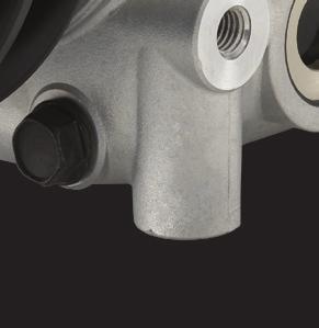
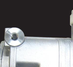
19 3- Handling instructions Opacity Color change Foreign substances Metal filings Oil contamination Unlike engine oil, no cleaning agent is added to the compressor oil. Even if the compressor is run for a long period (approximately 1 season), the oil never becomes turbid as long as there is nothing wrong with the compressor or its method of use. Inspect the extracted oil for any of the following : Increased opacity of the oil. Color change to red. Presence of foreign matter, metal filings, etc. WARNING! When system (oil) contamination is found during compressor replacement, flush the A/C system with a fluid that meets SAE J2670 and replace the drier (or accumulator). Oil filler plug O-ring Charge specified quantity of compressor oil Oil check The compressor oil must be checked as follows when being charged into a used system. 1. Perform the oil return operation (see p.16). 2. Remove the compressor from the vehicle. 3. Remove the oil filler plug and drain the oil through the oil filler plug and the high and low pressure connectors. 4. Check the oil for contamination. 5. Fill the compressor with the specified amount of oil through the oil filler plug (see p. 18)
20 3- Handling instructions unit: cm 3 & cc Specified charge 500 unit: cu in Specified charge 30.5 Amount recovered 350 or more Under 350 Amount recovered 21.4 or more Under cm 3 (6.1cu in) Current Compressor is kept Charging amount Same as recovered Compressor is replaced Amount to remove from new compressor 500-(amount recovered + 20) Current Compressor is kept Charging amount Same as recovered Compressor is replaced Amount to remove from new compressor 30.5-(amount recovered + 1.2) cm 3 (3.7cu in) CAUTION! The specified oil quantity differs, depending on the type of air conditioning system. A label describing the specified quantity is attached to the compressor. Additionally, all of the oil cannot be removed when draining the compressor, as some remains as an oil film on the inside of the compressor and the system components. Therefore, refer to the table at the left when recharging the compressor with oil. Excess oil adversely affects the cooling capacity and the compressor. 6. Install the oil filler plug and tighten it to the specified torque. Specified torque: 14 ~ 16 N m {1.4 ~ 1.6 kgf m, 10.3 ~ 11.8 lbf ft} CAUTION! The oil filler plug O-ring must be replaced with a new one. Replacement of components When replacing the system s component parts, supply the following amount of oil to the compressor. 30cm 3 (1.8cu in) Component mounted Evaporator Condenser Receiver drier Pipe or hose Amount of oil 100 cm 3 (6.1 cu in) 60 cm 3 (3.7 cu in) 30 cm 3 (1.8 cu in) 30 cm 3 (1.8 cu in) After installing these component parts, check the compressor oil. (See p.16)
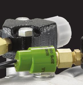
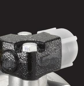
21 3- Handling instructions High pressure connector O-ring Flexible hose Low pressure connector Running-in operation Whenever moving parts have been replaced, it is necessary to run-in both the compressor and the magnetic clutch. Compressor running-in Reassembled compressors must be run-in after the leak test (see next page). 1. Check that the compressor contains the specified amount of oil. 2. Install the compressor on the test bench. 3. Install the high pressure connector ( ) and the low pressure connector ( ) to the ports and tighten the bolts to the specified torque. Specified torque: 20 ~ 24 N m {2.0 ~ 2.4 kgf m, 14 ~ 17 lbf ft} 4. Connect the two connector ports using a flexible hose. 5. Run the compressor at 1,000 rpm for at least 30 minutes. 6. Replace the oil. 7. Repeat the leak test. CAUTION! While the compressor is being run-in in step 5 above, check the outside temperature of the front head. If the temperature exceeds 80 C (176 F), stop the running-in operation. Resume the operation when the head has cooled. Magnetic clutch running-in OFF ON (50 times) 1. Install the clutch on the compressor. 2. Install the compressor on the test bench, and operate the compressor by running the system. 3. Maintain the compressor speed at 500 rpm. Operate the A/C switch through the ON/ OFF cycle at least 50 times ( ON for 10 seconds and OFF for 10 seconds)
22 3- Handling instructions Valve assembly ( ) Leak test The compressor must be checked for refrigerant leaks after it is repaired. The procedure is as follows. 1. Fit plates to the suction and discharge connections, and tighten it to the specified torque. Specified torque: 20 ~ 24 N m {2.0 ~ 2.4 kgf m, 14 ~ 17 lbf ft} 2. Using the valve assembly ( ), fill the compressor with refrigerant through the suction side, raising the refrigerant pressure to at least 0.49 MPaG {5 kgf/cm 2, 71 psig}. 3. Check the compressor for leaks using a leak detector. Gas leak detector Refrigerant charging In order to prevent a liquid charge and greatly increase risks of compressor dammage, do not shake or turn the refrigerant bottle upsidedown. Parts No. FRAGILE UP FRAGILE Air Conditioning Compressor UP VALEO Japan Co Ltd, MADE IN JAPAN Storing a repaired compressor If it is necessary to store a repaired compressor for some time before installation, evacuate the compressor and fill it with dry nitrogen gas through the suction fitting to raise the pressure to 49~150kPa {0.5~1.5kgf/cm 2, 7.1~21psig}
23 4- Troubleshooting Compressor troubleshooting When a problem occurs during the compressor operation, it is often difficult to pinpoint exact the cause of the malfunction. As long as the compressor maintenance is done correctly, there should not be any problem throughout the whole vehicle life, but should it happen, we hope this troubleshooting can help you solve the issue efficiently. Below are listed most of the issues you may encounter while the A/C is ON. Please refer to the compressor troubleshooting tree to localize the malfunction symptom, then look at the table (p.22-23) for the appropriate counter measure. Most of the malfunction symptoms can be classified in the following categories: 1. Insufficient cooling capacity 2. Abnormal noise 3. Smoke In case of insufficient cooling capacity, we recommend that you prepare a gauge manifold to measure the pressure of both discharge and suction sides (for a detailed diagnosis by gauge pressure, see p.24-25). Compressor troubleshooting tree 1. Insufficient cooling capacity A. Compressor is not running B. Compressor is running C. Compressor runs intermittently 2. Abnormal noise A. Abnormal noise from compressor B. Abnormal noise from magnetic clutch C. Belt slipping noise 3. Smoke A. Magnetic clutch friction surface slipping B. Magnetic clutch belt slipping C. Smoke from magnetic clutch D. Smoke from compressor
24 4- Troubleshooting 1. Insufficient cooling capacity Issue Symptom Possible cause Measure Compressor is not running (No cool blow coming out) Magnetic clutch slips when turning on the A/C switch Low pressure cut switch operate (see p.24-25) Compressor internal part damage Refrigerant shortage Replace the compressor Fix the refrigerant leakage then fill with refrigerant until reaching the right amount The magnetic clutch slips or does not engage when the compressor runs Lead wire short circuit or wiring connector not seated properly Replace the lead wire if it is defective A Magnetic clutch damage Magnetic clutch air gap too wide Repair or replace the magnetic clutch Adjust air gap or replace magnetic clutch Low magnetic clutch voltage Charge battery The magnetic clutch engages but the armature does not rotate Belt slipping Replace the compressor if it is locked Belt run off the pulley Compressor internal part damage or magnetic clutch damage Replace the compressor or the magnetic clutch Center bolt is loose / Center bolt is missing Bolt drop off/ Armature drop off Replace magnetic clutch Compressor is running (No cool blow coming out) Compressor is running normally No difference of temperature between discharge side and suction side (see p.24-25) Poor compression Refrigerant shortage Replace the compressor Fix the refrigerant leakage then fill with refrigerant until reaching the right amount B The magnetic clutch slips or does not engage when the compressor is running Magnetic clutch friction surface slipping Charge the battery or replace the magnetic clutch Loose connection of the magnetic clutch electrical circuit Replace the magnetic clutch after making sure it is defective Belt slipping Magnetic clutch belt slipping Belt tension readjustment The magnetic clutch does not engage Defective sensor Replace the sensor after making sure it is defective C Compressor runs intermittently (Cool blow comes out only from time to time) Both discharge and suction pressures are high The magnetic clutch slips or does not engage when the compressor is running Excess of refrigerant Condenser fan failure Loose connection of the magnetic clutch electrical circuit Reduce the refrigerant charge until reaching the right amount Replace the condenser after making sure it is defective Replace the magnetic clutch after making sure it is defective The magnetic clutch does not engage Defective sensor Replace the sensor after making sure it is defective
25 4- Troubleshooting 2. Abnormal noise A Issue Symptom Possible cause Measure Abnormal noise from the compressor Abnormal vibration after turning on the A/C switch Abnormal noise from the compressor body Compressor installation bolt is loose Wide gap at the attaching portion between the compressor and the bracket Compressor body internal component damage Increase tightening torque of the loose bolts Improve the compressor attaching portion Replace the compressor B Abnormal noise from the magnetic clutch The magnetic clutch has a backlash and slips Strange noise when the magnetic clutch engages Magnetic clutch damage Air gap too wide Replace the magnetic clutch Adjust air gap or replace magnetic clutch Armature slips / does not engage when the compressor is running Magnetic clutch friction, slippery surface Charge battery or replace magnetic clutch C Belt slipping noise Armature does not rotate when magnetic clutch engages Belt slipping Replace the compressor if locked. Readjust the belt tension if the belt is loose 3. Smoke Issue Symptom Possible cause Measure A Magnetic clutch friction surface slipping The magnetic clutch slips / does not engage when the compressor is running Magnetic clutch air gap too wide Low magnetic clutch voltage Adjust air gap or replace magnetic clutch Charge battery Magnetic clutch friction, greasy surface Clean friction surface or replace magnetic clutch B Magnetic clutch belt slipping The magnetic clutch slips / does not engage when the compressor is running Belt alignment is not correct Magnetic clutch belt is greasy Adjust the compressor installation position Clean or replace the belt Magnetic clutch belt tension is loose Adjust belt tension C Smoke from the magnetic clutch The magnetic clutch does not engage Coil open or shorted Replace the magnetic clutch D Smoke from the compressor Refrigerant / oil is blowing out Refrigerant leaking, uncoupled piping or piping burst Fix the refrigerant leakage then fill with refrigerant until having the right amount
26 4- Troubleshooting A/C cycle diagnosis by gauge pressure Following is a diagnosis procedure to connect gauge manifold to A/C cycle, measure suction and discharge pressures and analyze the defects of the cycle. Operation conditions of the A/C cycle for pressure measuring: 1. Ambient temperature: C 2. Engine speed: 1,500 rpm 3. A/C switch: ON 4. Blower speed: high 5. Temperature control: full cold Gauge pressure indication Pressure is normal Cause Confirmation method Action to take A/C cycle operates normally. If there is any defect (poor cooling performance), there must be another cause Discharge pressure: around MPaG (10-17 kgf/cm²) Suction pressure: around MPaG ( kgf/cm²) Both discharge and suction pressures are low Suction pressure becomes vacuum Refrigerant shortage Receiver dryer is clogged Connect gauge manifold to cycle Temperature difference between inlet and outlet pipes. Dryer is covered with frost Recover refrigerant, then refill with the right amount of refrigerant Replace parts Expansion valve is clogged Expansion valve was covered with frost Clean or replace part Enclosure leakage from Expansion valve s temperature sensing tube. (Expansion valve operates to close the valve opening) Temperature sensing device at outlet air is defective Refrigerant piping is clogged or crashed Outlet side of Expansion valve is not cooling. (Low side of gauge indicates vacuum) Evaporator becomes frozen up If any part between the dryer and the compressor is clogged or crashed, the low side pressure becomes vacuum Replace part Adjust or replace the part Adjust or replace the part
27 4- Troubleshooting Gauge pressure indication Both discharge and suction pressures are high Discharge pressure is high and suction pressure is low Discharge pressure is low and suction pressure is high Cause Confirmation method Action to take Excess of refrigerant Condenser cooling malfunction Misaligned Expansion valve or thermal sensing tube of the Expansion valve is not fit on regularly. (Excess opening of Expansion valve) Air mixed in refrigeration cycle Refrigerant cycle is clogged between compressor and condenser Defect of the compressor valve or gasket Connect gauge manifold to cycle Condenser becomes muddy and fins are clogged and collapsed. Defect of cooling fan rotation. Malfunction of fan motor for condenser. Defective refrigerant flow control, the thermal sensing tube is not closely in contact with the evaporator pipe Just after compressor stops, discharge pressure will come down immediately to MPaG (3-4 kgf/cm²) Appreciable temperature difference at the clogged location Discharge and suction pressures balance immediately after the compressor stops. (Defective compression of compressor) Recover refrigerant, then refill with the right amount of refrigerant Clean up, hand repair of fin and replacement Adjustment or replacement Evacuate air from cycle, the charge with the adequate amount of refrigerant Clean up inside the cycle or replace the part Replace the compressor
28 5- Tightening torques Unit : N m {kgf m, lbf ft.} Part Thread size Tightening torque 1. Center bolt M8 x { , 14-16} 2. Field coil screws M6 x { , } 3. Bolt M10 x { , 18-22} 4. Oil filler plug M10 x { , 10-12} 5. Connector bolt M8 x { , 14-17} for connectors
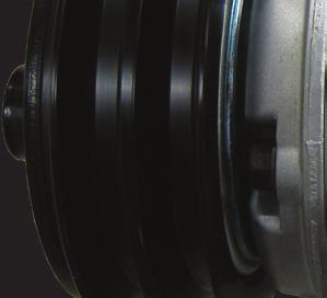
29 6- Service procedures - Magnetic clutch Drive plate holder Magnetic clutch Removal 1. Remove the center bolt using the drive plate holder ( ) to prevent the armature assembly from rotating. 2. Remove the armature assembly. External snap ring pliers 3. Remove the snap ring using external snap ring pliers. Snap ring Center pulley puller Pulley puller Position the center pulley puller ( ) at the end of the driveshaft. 5. Attach a suitable pulley puller to the pulley. Hook the puller claws to the edge of the pulley as shown. 6. Tighten the center pulley puller bolt to remove the pulley. CAUTION! Do not clip the puller claws into the pulley groove to prevent pulley groove damage.
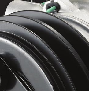
30 6- Service procedures - Magnetic clutch Remover Lead wire bushing 5. Remove the lead wire bushing of the field coil using the remover ( ). 6. Remove the three field coil/compressor screws. Then remove the field coil. CAUTION! Do not hold the field coil by the harness. Inspection Armature assembly Pulley assembly Field coil 1. If the contact surface has been damaged by excessive heat, the armature and pulley must be replaced. 2. Check the appearance of the pulley assembly. If the contact surface of the pulley is excessively grooved due to slippage, both the pulley and the armature must be replaced. The contact surface of the pulley assembly must be cleaned with a suitable solvent before reinstallation. 3. Check the field coil for a loose connector or cracked insulation
31 6- Service procedures - Magnetic clutch Screws Lead wire bushing Magnetic clutch Installation 1. Install the field coil on the compressor (with the harness on top) and tighten the mounting screws to the specified torque. Specified torque: 4.2 ~ 7.2 N m {0.4 ~ 0.7 kgf m, 3.1 ~ 5.3 lbf ft} Field coil Pulley assembly Press Installer Carefully place the wire harness bushing. 3. Install the pulley assembly using the pulley installer ( ) and a hand press. 4. Install the snap ring (beveled edge up) using external snap ring pliers. Snap ring External snap ring pliers
32 6- Service procedures - Magnetic clutch Drive plate Adjusting shims Drive plate holder Install the armature assembly on the driveshaft together with the original shim(s). Press the armature assembly down by hand. 6. Install the center bolt and tighten to the specified torque using the drive plate holder ( ) to prevent the armature assembly from the rotating. Specified torque: 20 ~ 22 N m {2.0 ~ 2.2 kgf m, 14 ~ 16 lbf ft} CAUTION! After tightening the center bolt, check that the pulley rotates smoothly. Gap adjustment 0.3~0.6 mm Thickness gauge 7. Check that the clutch clearance is as specified. If necessary adjust the clearance using shim(s). Adjusting shims are available in the following thickness : Shim Part No. Thickness mm (0.004 in) mm (0.012 in) mm (0.020 in) mm (0.031 in) Specified clearance: 0.3 ~ 0.6 mm {0.01 ~ 0.02 in} 8. Run-in the clutch as described on page
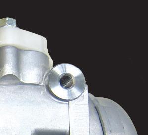
33 7- Service procedures - Shaft seal assembly Shaft seal assembly Removal 1. Remove the magnetic clutch assembly as described on page Remove the four bolts securing the connectors, and then remove the connectors and strainer from the cylinder shaft assembly. 3. Remove the oil filler plug and then drain the oil. 4. Remove the five bolts securing the heads. Tap lightly 5. Alternately tap the two projections on the front head using the remover ( ) and a mallet to remove the front cylinder head. Remover Front cylinder head Press uniformly from above Shaft seal 6. Remove the shaft seal assembly using the remover ( ). Front cylinder head Remover
34 7- Service procedures - Shaft seal assembly Inspection The shaft seal must not be reused. Always use a new shaft seal when reassembling the compressor. Ensure that the seal seat is free from lint and dirt that could damage the shaft seal lip. Shaft seal Press using a press Remover Front cylinder head Installation 1. Clean the portion of the front cylinder head where the shaft seal is to be assembled. 2. Assemble the shaft seal on the remover ( ). 3. Coat the shaft seal well with compressor oil and install the shaft seal in the front cylinder head. 4. Remove the shaft seal remover. O-ring Guide Front cylinder head 5. Position the guide ( ) on the shaft. 6. Coat the new O-ring with clean compressor oil and install it in the front cylinder head. 7. Install the front cylinder head. CAUTION! Align the roll pins and tap the head lightly and evenly with a plastic hammer. 8. Remove the guide ( ). 9. Install the five bolts from the front cylinder head side and tighten them to the specified torque. Specified torque: 25 ~ 30 N m {2.5 ~ 3.0 kgf m, 18 ~ 22 lbf ft} Tighten each bolt gradually (in three or more stages) to ensure the specified torque. 10. Turn the drive shaft 2 ~ 3 times by hand to ensure that the shaft rotates smoothly
35 7- Service procedures - Shaft seal assembly Oil filler plug O-ring 11. Fill the compressor with the specified amount of clean compressor oil through the oil filler. 12. Install the oil filler plug with a new O-ring, and tighten it to the specified torque. Specified torque: 14 ~ 16 N m {1.4 ~ 1.6 kgf m, 10 ~ 12 lbf ft} 13. Install the strainer in the suction port. When the connectors are installed 14. Fit plates to the suction and discharge connections, and tighten them to the specified torque. Specified torque: 20 ~ 24 N m {2.0 ~ 2.4 kgf m, 14 ~ 17 lbf ft} 15. Install the magnetic clutch as described on page Run-in the compressor as described on page Perform the leak test as described on page
36 8- Service procedures - Cylinder head Cylinder heads (Front & Rear) Disassembly 1. Remove the magnetic clutch assembly as described on page Remove the four bolts securing the connectors, and then remove the connectors and strainer from the cylinder shaft assembly. 3. Remove the oil filler plug and then drain the oil. 4. Remove the five bolts securing the heads. Tap lightly 5. Alternately tap the two projections on the front head using the remover ( ) and a mallet to remove the front cylinder head. Remover Front cylinder head Suction valve Gasket 6. Remove the front valve plate assembly and then the suction valve (in that order). 7. Remove and discard the O-ring from the front cylinder head. 8. Remove all gasket material from the front cylinder head and the front valve plate. Valve plate assembly O-ring
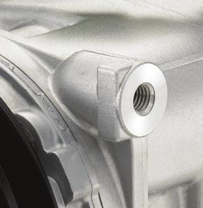
37 8- Service procedures - Cylinder head Bolts Rear cylinder head 9. Screw two bolts into the opposite sides of the rear cylinder head and tap alternate bolts lightly with a plastic hammer to remove the head. CAUTION! Screw the bolts fully into the head to prevent rear head thread damage. Tap lightly Suction valve Gasket Gear 10. Remove the rear valve plate assembly and then the suction valve (in that order). 11. Remove and discard the O-ring from the rear cylinder head. 12. Remove all gasket material from the rear cylinder head and the rear valve plate. Valve plate assembly O-ring 13. Remove the gear pump from the rear cylinder head or the end of the driveshaft. Gear pump Rear cylinder head
38 8- Service procedures - Cylinder head Valve plate Cylinder head Inspection Check the front and rear valve plates for scratched, bent or damaged parts. Inspect both cylinder heads and both valve plates for nicks or burrs on the sealing surfaces. Clean both cylinder heads and both valve plates or replace them if they are cracked or damaged. Check that none of the passages in the valve plates are blocked
39 8- Service procedures - Cylinder head Escape groove Reassembly Rear cylinder head 1. Place the cylinder shaft assembly on the bench with the rear side up. 2. Install the rear suction valve so that it matches the roll pins. CAUTION! Ensure each valve matches each cylinder valve escape groove. 3. Install the rear valve plate on the rear suction valve. CAUTION! Do not mistake the front and rear valve plates. Gear pump 4. Coat the new gasket with clean compressor oil and install it on the rear valve plate. 5. Coat the new gear pump with clean compressor oil and install it on the end of the drive shaft. O-ring Valve plate assembly Rear cylinder head Gear Gasket Suction valve 6. Coat the new O-ring with clean compressor oil and install it on the rear cylinder head. 7. Install the rear cylinder head. When positioning the head, ensure the gear pump is inserted into the hole in the cylinder head. Roll pins
40 8- Service procedures- Cylinder head O-ring Valve plate assembly Guide Roll pins Oil filler plug O-ring Front cylinder head Gasket Suction valve Front cylinder head 1. Place the cylinder shaft assembly on the bench with the front side up. 2. Install the front suction valve so that it matches the spring pins. CAUTION! Ensure each valve matches each cylinder s valve escape groove. 3. Install the front valve plate on the front suction valve. 4. Coat the new gasket with clean compressor oil and install it on the front valve plate. 5. Position the guide ( ) on the shaft. 6. Coat the new O-ring with clean compressor oil and install it on the front cylinder head. 7. Install the front cylinder head. CAUTION! Align the roll pins and tap the head lightly and evenly with a plastic hammer. 8. Remove the guide ( ). 9. Install the five bolts from the front cylinder head side and tighten them to the specified torque. Specified torque: 25 ~ 29 N m {2.5 ~ 3.0 kgf m, 18 ~ 22 lbf ft} Tighten each bolt gradually (in three or more stages) to ensure the specified torque. 10. Turn the drive shaft 2 ~ 3 times by hand to ensure that the shaft rotates smoothly. 11. Fill the compressor with the specified amount of clean compressor oil through the oil filler. 12. Install the oil filler plug with a new O-ring, and tighten it to the specified torque. Specified torque: 14 ~ 16 N m {1.4 ~ 1.6 kgf m, 10 ~ 12 lbf ft} 13. Install the strainer in the suction port. When the connectors are installed 14. Fit blanking plates to the suction and discharge connections, and tighten it to the specified torque. Specified torque: 20 ~ 24 N m {2.0 ~ 2.4 kgf m, 14 ~ 17 lbf ft} 15. Install the magnetic clutch (see p. 29). 16. Run-in the compressor (see p.19). 17. Perform the leak test (see p. 20)
41 9- Service tools In addition to standard tools, numerous special tools are necessary to service the Valeo TM31 compressor. The use of these special tools enables prompt and correct compressor service. The special tools are classified into three groups: those for magnetic clutch disassembly and reassembly; those for compressor disassembly and reassembly; and those for testing and running-in operation. MAGNETIC CLUTCH TOOLS Part name Part No. Shape Reference page Application Drive plate holder For fixing drive plate Center pulley puller For removing pulley Remover For removing lead wire bushing Installer For installing pulley
42 9- Service tools Compressor tools Part name Part No. Shape Remover Reference page Application For removing cylinder head and cylinder block Remover For removing and installing shaft seal Guide For installing shaft seal Test and inspection tools Part name Part No. Shape Reference page Application Connector For high pressure port Connector For low pressure port O-ring For maintaining connector air tightness Valve assembly For charging refrigerant Gas leak detector For detecting gas leaks
43
44
45 10- Service parts 1. Compressor body service kits, sets and parts Item* Part name Reference Quantity OVERHAUL KIT (O-RING SET + GASKET SET + SHAFT SEAL) 2. Oil O-RING SET ,20 O-ring body (front & rear head) n=2 18 O-ring drain n=1 GASKET SET Gasket front head n=1 23 Gasket rear head n=1 9 Gasket (bolt) 7 per set n=7 SHAFT SEAL (for service) Shaft seal n=1 OTHER COMPRESSOR PARTS Valve plate assy (front) n=1 22 Valve plate assy (rear) n=1 14,21 Suction valve n=2 * see product description - Exploded view p.7 Item Part name Reference Quantity - ZXL 100PG cc
46 Notes
47 VALEO JAPAN - TM31 for HFC-134a use SERVICE MANUAL Version: WW EN Published by: VALEO JAPAN CO, LTD. Copyright 2017, VALEO JAPAN CO, LTD. For any inquiry regarding the present service manual, contact us at vc-oura-sales@valeo.com

48
SERVICE MANUAL. Valeo TM21Compressor. Copyright 2015 Valeo Japan CO., LTD. All rights reserved.
 SERVICE MANUAL Valeo TM21Compressor Copyright 2015 Valeo Japan CO., LTD. All rights reserved. Foreword This service manual has been elaborated to help service personnel to provide efficient and correct
WARNINGS. Maintenance must be properly done to avoid serious injury risks. Improper maintenance can result in injury or property damage.
 Foreword This service manual has been elaborated to help service personnel to provide efficient and correct service and maintenance on the TM21 model compressors (for HFC-134a) for automotive air conditioning.
SERVICE MANUAL. Valeo TM08, TM13, TM15 & TM16 Compressors. Copyright 2013 Valeo Japan CO., LTD. All rights reserved.
 SERVICE MANUAL Valeo TM08, TM13, TM15 & TM16 Compressors Copyright 2013 Valeo Japan CO., LTD. All rights reserved. Foreword This service manual has been elaborated to help service personnel to provide
MANUAL CONTROL / SEMIAUTO TEMPERATURE CONTROL HEATING, VENTILATION AND AIR CONDITIONING SYSTEM
 SECTION 7C MANUAL CONTROL / SEMIAUTO TEMPERATURE CONTROL HEATING, VENTILATION AND AIR CONDITIONING SYSTEM CAUTION: Disconnect the negative battery cable before removing or installing any electrical unit
AIR CONDITIONING SYSTEM
 AC-1 AIR CONDITIONING SYSTEM GENERAL INFORMATION DESCRIPTION TROUBLESHOOTING PREPARATION REFRIGERATION SYSTEM DRIVE BELT REFRIGERATION LINES COMPRESSOR RECEIVER CONDENSOR COOLING UNIT COOL/ICE BOX EVAPORATORS
UX330 Compressor Service Manual
 UX330 Compressor Service Manual UX330 Compressor Service Manual Table of contents: 1. Specifications UX330. 1 Magnetic clutch 2 2. Component part list I. Compressor part numbers 3 II. Exploded view 4 3.
A Series UP90 UP120 UP150 UP170 Compressor Service Manual
 TM A Series UP90 UP120 UP150 UP170 Compressor Service Manual A Group Compressor Service Manual Table of contents: 1. Specifications UP90/UP120/UP150/UP170. 1 Magnetic clutch 2 Rear cap.2 2. Component
COMPRESSORS REPLACEMENT PROCEDURE
 COMPRESSORS REPLACEMENT PROCEDURE INTRODUCTION Shown below, you can find the procedure that you must follow to replace compressors. INSTALLATION INSTRUCTION Steps to follow: 1) Remove the damaged compressor
Section 10 Chapter 17
 Section 10 Chapter 17 24 Valve, 8.3 Liter Engine Air Intake System Note: All coding used in the 8.3 Liter and 9 Liter engine manuals are Cummins engine codes. These engine codes have no meaning to New
HEATER, AIR CONDITIONER AND VENTILATION
 55-1 HEATER, AIR CONDITIONER AND VENTILATION CONTENTS HEATER AND MANUAL AIR CONDITIONER...................... 3 GENERAL............................... 3 Outline of Change......................... 3 SERVICE
ENGINE LUBRICATION & COOLING SYSTEMS SECTIONLC CONTENTS. ENGINE LUBRICATION SYSTEM...2 Precautions...2
 ENGINE LUBRICATION & COOLING SYSTEMS SECTIONLC CONTENTS ENGINE LUBRICATION SYSTEM...2 Precautions...2 LIQUID GASKET APPLICATION PROCEDURE...2 Preparation...2 SPECIAL SERVICE TOOLS...2 Lubrication Circuit...3
Repair any problems or leaks before retrofitting. Affix labels to the vehicle showing conversion status. Observe all safety recommendations.
 The use of R134a in mobile A/C systems designed for R-1 2 refrigerant causes higher discharge pressures (as much as 10-15%) and necessitates changing the compressor lubricant from mineral oil (5GS) to
BRAKE E
 8-1 GENERAL...8-2 SPECIFICATIONS...8-6 COMPONENTS...8-7 FRONT BRAKE...8-12 DISASSEMBLY INSPECTION REASSEMBLY (Pn1, Cu2 3 TON SERIES)...8-12 DISASSEMBLY INSPECTION REASSEMBLY (Pn2 3 TON SERIES)...8-17 BRAKE
POWER STEERING TO INDEX POWER STEERING SYSTEM PRECAUTIONS... OPERATION CHECK... PROBLEM SYMPTOMS TABLE... VANE PUMP ASSEMBLY COMPONENTS...
 TO INDEX STEERING POWER STEERING POWER STEERING SYSTEM PRECAUTIONS.............................................. OPERATION CHECK......................................... PROBLEM SYMPTOMS TABLE.................................
INSTALLATION INSTRUCTIONS
 INSTALLATION INSTRUCTIONS Accessory Application Publications No. AIR CONDITIONER CIVIC 2- AND 4-DOOR AII 24158 Issue Date SEP 2002 What s New The installation instructions for the 2003 Civic A/C are the
SERIES PC INSTRUCTION AND OPERATION MANUAL
 MEGGA SERIES PC INSTRUCTION AND OPERATION MANUAL Models PCT and PCF Close-coupled and frame-mounted single-stage horizontal end-suction pumps. WARNING: Read this manual before installing or operating this
ENGINE COOLING SYSTEM
 B ENGINE A SECTION ENGINE COOLING SYSTEM CO C D CONTENTS E PRECAUTIONS... 2 Precautions for Liquid Gasket... 2 REMOVAL OF LIQUID GASKET SEALING... 2 LIQUID GASKET APPLICATION PROCEDURE... 2 PREPARATION...
COOLING SYSTEM. Return to Main Table of Contents
 COOLING SYSTEM Return to Main Table of Contents GENERAL... 2 COOLING SYSTEM... 7 RADIATOR... 9 ENGINE COOLANT PUMP... 12 THERMOSTAT... 14 ENGINE COOLANT TEMPERATURE SENDER &, SENSOR... 15 ENGINE COOLANT
Air Trap TATSU2. Copyright 2013 by TLV CO., LTD. All rights reserved ISO 9001/ ISO M-02 (TATSU2) 7 August 2013.
 7 August 2013.") 172-65177M-02 (TATSU2) 7 August 2013 ISO 9001/ ISO 14001 Manufacturer Kakogawa, Japan is approved by LRQA LTD. to ISO 9001/14001 Air Trap TATSU2 Copyright 2013 by TLV CO., LTD. All rights reserved 1 Contents
172-65177M-02 (TATSU2) 7 August 2013 ISO 9001/ ISO 14001 Manufacturer Kakogawa, Japan is approved by LRQA LTD. to ISO 9001/14001 Air Trap TATSU2 Copyright 2013 by TLV CO., LTD. All rights reserved 1 Contents
AIR CONDITIONER SECTION AC CONTENTS AUTO
 AIR CONDITIONER SECTION AC CONTENTS AUTO PRECAUTIONS AND PREPARATION SRS Airbag Pretensioner Seatbelt... 4 A/C Refrigerant HFC134a Handling... 4 Compressor Oil... 4 Tube Connection... 4 O-Ring Part Number...
HIGH FUEL PRESSURE LINE
 16 07 HIGH FUEL PRESSURE LINE High Pressure Pump Description This pump generates high fuel pressure and is driven by timing chain (radial plunger principle). This pump pressurizes the fuel to approx. 1600
A/C COMPRESSOR SERVICING Article Text 1991 Saab 9000 For Copyright 1997 Mitchell International Friday, October 15, :22PM
 Article Text ARTICLE BEGINNING 1991 GENERAL SERVICING Compressor Service * PLEASE READ THIS FIRST * CAUTION: When discharging air conditioning system, use only approved refrigerant recovery/recycling equipment.
Service Manual. Climate Control Inc.
 SECTION 2 Service - Clutch Servicing (Removal & Installation) - Shaft Seal Servicing (Removal & Installation) - Head & Valve Plate Servicing (Removal & Installation) - Baseplate Servicing (Removal & Installation)
Technical Service BULLETIN
 Technical Service BULLETIN Title: Models: 01 03 Sequoia TSB UPDATE NOTICE: The information contained in this TSB supercedes TSBs AC001 01 and AC001 02. The previous TSBs, AC001 01 and AC001 02, should
TURBOCHARGER SYSTEM TURBOCHARGER TC 1
 TURBOCHARGER SYSTEM TURBOCHARGER TC1 TC2 TURBOCHARGER SYSTEM Description DESCRIPTION Systems which increase the amount of air sent to the engine are either turbocharger type (using exhaust gas to turn
TURBOCHARGER Toyota Celica DESCRIPTION OPERATION TURBOCHARGING SYSTEMS All Models
 TURBOCHARGER 1988 Toyota Celica 1988 TURBOCHARGING SYSTEMS All Models DESCRIPTION Most models use a water-cooled turbocharger, mounted directly to the exhaust manifold with a wastegate assembly attached
A/C SYSTEM GENERAL DIAGNOSTIC PROCEDURES
 Article Text ARTICLE BEGINNING 1993 AIR CONDITIONING & HEAT A/C General Diagnostic Procedures Diagnosis is an important first step in A/C system servicing. To save time and effort, systems should be carefully
5/21/2018 G 3.3 DOHC > Heating,Ventilation, Air Conditioning > Air conditioning System > Compressor > Repair procedures 2009 Hyundai Sonat
 2009 Sonata Report a problem with this article Removal 1. If the compressor is marginally operable, run the engine at idle speed, and let the air conditioning work for a few minutes, then shut the engine
High Performance Vacuum Pump Model 15120A/15121A Operating Manual...
 High Performance Vacuum Pump Model 15120A/15121A Operating Manual... Operating Manual Table of Contents Warnings...1 CoolTech high performance vacuum pumps...1 Pump components...2 Before using your vacuum
Call the A/C Experts SD Compressor Service Guide
 Call the A/C Experts SD Compressor Service Guide Table of Contents 1. Compressor Models Covered 2. Compressor Nomenclature 3. Cautionary Information 3.1 Pressure Release 3.2 Recovery of Refrigerant 3.3
REMOVAL & INSTALLATION
 REMOVAL & INSTALLATION NOTE: For reassembly reference, label all electrical connectors, vacuum hoses and fuel lines before removal. Also place mating marks on engine hood and other major assemblies before
2004 IMPREZA SERVICE MANUAL QUICK REFERENCE INDEX
 2004 IMPREZA SERVICE MANUAL QUICK REFERENCE INDEX ENGINE SECTION 1 FU(H4SO) EMISSION CONTROL (AUX. EMISSION CONTROL DEVICES) INTAKE (INDUCTION) EC(H4SO) IN(H4SO) This service manual has been prepared to
POWER STEERING SYSTEM
 SYSTEM 511 SYSTEM PRECAUTION 5105K01 1. HANDLING PRECAUTIONS ON STEERING SYSTEM (a) Care must be taken to when replacing parts. Incorrect replacement could affect the performance of the steering system
Bearing Handling. 15. Bearing Handling Bearing storage Installation
 15. Bearing Handling Bearings are precision parts and, in order to preserve their accuracy and reliability, care must be exercised in their handling. In particular, bearing cleanliness must be maintained,
Models
 Models 15300 15301 15500 15501 SAFETY PRECAUTIONS WARNING! To prevent personal injury, Wear goggles when working with refrigerants. Contact with refrigerants may cause injury. Incorrect use or connections
Compressor - Install (E.40.C.31 - F.10.A.15)
") Compressor - Install (E.40.C.31 - F.10.A.15) 1. Set the compressor on its mount and secure into place using the four bolts. Connect the refrigerant suction line (5) and the discharge line (4). Install
Compressor - Install (E.40.C.31 - F.10.A.15) 1. Set the compressor on its mount and secure into place using the four bolts. Connect the refrigerant suction line (5) and the discharge line (4). Install
Radiator Service Tool Set Hexagon Wrench Set TOYOTA Electrical Tester Set. Capacity
 ENGINE EG329 PREPARATION SST (SPECIAL SERVICE TOOLS) 0923001010 Radiator Service Tool Set 0923114010 Punch 2JZGE only (Aluminum type) RECOMMENDED TOOLS 0904000010 Hexagon Wrench Set 0908200050 TOYOTA Electrical
INSTRUCTION MANUAL INTERNAL GEAR PUMP TITAN G-4124A SERIES=> FLANGED TITAN G-124A SERIES => FLANGED MODELS:
 INSTRUCTION MANUAL INTERNAL GEAR PUMP TITAN G-4124A SERIES=> FLANGED TITAN G-124A SERIES => FLANGED MODELS: G-H, G-HL, G-K, G-KK, G-L, G-LQ, G-LL, GLS, G-Q, G-QS 1 Contents Maintenance Thrust bearing adjustment
OVERHAUL 1. REMOVE OIL FILLER CAP SUB ASSY. 2. REMOVE CYLINDER HEAD COVER SUB ASSY (a) Remove the 10 bolts, 2 nuts, cylinder head cover and gasket.
 Remove the 10 bolts, 2 nuts, cylinder head cover and gasket.") 144 ENGINE MECHANICAL OVERHAUL 1. REMOVE OIL FILLER CAP SUBASSY 1410H01 2. REMOVE CYLINDER HEAD COVER SUBASSY (a) Remove the 10 bolts, 2 nuts, cylinder head cover and gasket. A11090 3. REMOVE CAMSHAFT
144 ENGINE MECHANICAL OVERHAUL 1. REMOVE OIL FILLER CAP SUBASSY 1410H01 2. REMOVE CYLINDER HEAD COVER SUBASSY (a) Remove the 10 bolts, 2 nuts, cylinder head cover and gasket. A11090 3. REMOVE CAMSHAFT
Free Float Air Trap G8
 172-65193MA-06 (G8) 24 June 2015 ISO 9001/ ISO 14001 Manufacturer Kakogawa, Japan is approved by LRQA LTD. to ISO 9001/14001 Free Float Air Trap G8 Copyright 2015 by TLV CO., LTD. All rights reserved 1
Installation Vertical Pump: Installation 'CM' and 'CDM' Style: Operation:
 Installation Vertical Pump: Gusher vertical end suction pumps with integral shaft is easily installed and put into service. With the one piece shaft design there is no couplings to align, no shims or no
COMPRESSOR REMOVAL OF MANIFOLD GAUGE SET ON VEHICLE INSPECTION AC 18 AIR CONDITIONING SYSTEM
 AC18 AIR CONDITIONING SYSTEM 5. CONNECT STOP VALVES TO SERVICE VALVES Tighten the nuts by hand. CAUTION: Do not connect the wrong valves to the high pressure and the low pressure sides. To prevent loosening
SERIES G3DB/AG3DB ELEVATOR
 TM INSTRUCTIONS AND PARTS LIST SERIES G3DB/AG3DB ELEVATOR WARNING This manual, and GENERAL INSTRUCTIONS MANUAL, CA-1, should be read thoroughly prior to pump installation, operation or maintenance. SRM00059
Model No. 668D3. COFFEPUMP Part No Product Code: O/C GJAN21.DB6B-DC310B
 Model No. 668D3 COFFEPUMP Part No. 9168 Product Code: O/C GJAN21.DB6B-DC310B OVERHAUL MANUAL with ILLUSTRATED PARTS LIST Page 1 of 15 P/N 5914 Rev D 01/17/05 1.0 Introduction 1.1 Description 1.1.1 The
Operating Manual. High Performance Vacuum Pump Models and 15600
 Operating Manual High Performance Vacuum Pump Models 15400 and 15600 CoolTech High Performance Vacuum Pumps Congratulations on purchasing one of Robinair s top quality CoolTech vacuum pumps. Your pump
13. CRANKCASE/CRANKSHAFT/BALANCER/PISTON/CYLINDER
 13. CRANKCASE/CRANKSHAFT/BALANCER/PISTON/CYLINDER COMPONENT LOCATION 13-2 SERVICE INFORMATION 13-3 TROUBLESHOOTING 13-4 CRANKCASE SEPARATION 13-5 CRANKSHAFT 13-7 MAIN JOURNAL BEARING 13-9 CRANKPIN BEARING
EG 18 ENGINE MECHANICAL TIMING BELT EG5EK 01 COMPONENTS FOR REMOVAL AND INSTALLATION
 EG18 ENGINE TIMING BELT COMPONENTS FOR REMOVAL AND INSTALLATION EG5EK01 ENGINE EG19 EG20 ENGINE ENGINE EG21 EG22 ENGINE TIMING BELT REMOVAL EG5G101 1. REMOVE OIL PAN PROTECTOR 2. REMOVE ENGINE UNDER COVER
ENGINE COOLING SYSTEM
 B ENGINE A SECTION ENGINE COOLING SYSTEM CO C D CONTENTS E PRECAUTIONS... 2 Precautions for Supplemental Restraint System (SRS) AIR BAG and SEAT BELT PRE-TEN- SIONER... 2 Precautions for Liquid Gasket...
Table of Contents. 4. Before a New Turbocharger is Installed
 Table of Contents 1. Turbocharger Overview ------------------------------------------------------------------ 1.1. Definition -----------------------------------------------------------------------------
Compressor HVAC: Service and Repair
 Compressor HVAC: Service and Repair Cooler Compressor Assy REPLACEMENT 1. DISCHARGE REFRIGERANT FROM REFRIGERATION SYSTEM SST 07110-58060 (07117-58080, 07117-58090, 07117-78050, 07117-88060, 07117-88070,
Jeep Wrangler TJ 4.0 LITER Installation instructions
 www.jeepair.com 2000-2001 Jeep Wrangler TJ 4.0 LITER Installation instructions Important information about your system, and warranty DO NOT ADD ANY OIL TO ANY PART OF THE SYSTEM. DO NOT USE THE SIGHT GLASS
WEBER CARBURETOR TROUBLESHOOTING GUIDE
 This guide is to help pinpoint problems by diagnosing engine symptoms associated with specific vehicle operating conditions. The chart will guide you step by step to help correct these problems. For successful
ENGINE TUNE-UP INSPECTION OF ENGINE COOLANT INSPECTION OF ENGINE OIL INSPECTION OF BATTERY. INSPECTION OF AIR FILTER (Paper Filter Type)
") ENGINE MECHANICAL - Engine Tune-Up EM-17 ENGINE TUNE-UP INSPECTION OF ENGINE COOLANT (See steps 1 and 2 on page CO-4) INSPECTION OF ENGINE OIL (See steps 1 and 2 on page LU-5) INSPECTION OF BATTERY (See
ENGINE MECHANICAL - Engine Tune-Up EM-17 ENGINE TUNE-UP INSPECTION OF ENGINE COOLANT (See steps 1 and 2 on page CO-4) INSPECTION OF ENGINE OIL (See steps 1 and 2 on page LU-5) INSPECTION OF BATTERY (See
GROUP CONTENTS GENERAL DESCRIPTION RADIATOR SPECIAL TOOL THERMOSTAT ENGINE COOLING DIAGNOSIS...
 14-1 GROUP 14 CONTENTS GENERAL DESCRIPTION 14-2 SPECIAL TOOL 14-2 ENGINE COOLING DIAGNOSIS 14-3 INTRODUCTION 14-3 TROUBLESHOOTING STRATEGY 14-3 SYMPTOM CHART 14-3 SYMPTOM PROCEDURES 14-4 ON-VEHICLE SERVICE
GENERAL SPECIFICATIONS 25-2 GENERAL. Water cooling, forced circulation with electric fan
 COOLING SYSTEM GENERAL 2 COOLING SySTEM 8 RADIATOR 10 RADIATOR FAN MOTOR ASSY 12 WATER PUMP 14 THERMOSTAT 16 WATER HOSE AND PiPE 17 WATER TEMPERATURE GAUGE UNIT AND SENSOR 18 GENERAL GENERAL Y25CAOA SPECIFICATIONS
2003 FORESTER SERVICE MANUAL QUICK REFERENCE INDEX
 2003 FORESTER SERVICE MANUAL QUICK REFERENCE INDEX ENGINE 2 SECTION FU(TURBO) EMISSION CONTROL (AUX. EMISSION CONTROL DEVICES) INTAKE (INDUCTION) EC(TURBO) IN(TURBO) This service manual has been prepared
ENGINE 6G74 3.5L-SOHC-24 VALVE
 11A ENGINE General Information/Service Specifications ENGINE 6G74 3.5L-SOHC-24 VALVE GENERAL INFORMATION Items Specifications Type V-type, Over Head Camshaft Number of cylinders 6 Bore mm 93.0 Stroke mm
Failure Mode Analysis
 Presented by: Brunno Covolan Pg. 1 : Introduction What is Failure Mode Analysis? Looking at the compressor to determine what was the cause of the failure. Why do we need to conduct Failure Mode Analysis?
Float Dynamic Steam Trap J10
 172-65237MA-01 (J10) 12 June 2015 ISO 9001/ ISO 14001 Manufacturer Kakogawa, Japan is approved by LRQA LTD. to ISO 9001/14001 Float Dynamic Steam Trap J10 Copyright 2015 by TLV CO., LTD. All rights reserved
ENGINE COOLING SYSTEM
 ENGINE SECTION CO A ENGINE COOLING SYSTEM CO C D CONTENTS E PRECAUTION... 2 PRECAUTIONS... 2 Precaution for Supplemental Restraint System (SRS) "AIR BAG" and "SEAT BELT PRE-TEN- SIONER"...2 Precaution
POWER ASSISTED SYSTEM (POWER STEERING)
") POWER ASSISTED SYSTEM (POWER STEERING) POWER ASSISTED SYSTEM (POWER STEERING) 1. General Description A: SPECIFICATION Model Whole system Gearbox Pump (Power steering system) Hydraulic oil (Power steering
POWER ASSISTED SYSTEM (POWER STEERING) POWER ASSISTED SYSTEM (POWER STEERING) 1. General Description A: SPECIFICATION Model Whole system Gearbox Pump (Power steering system) Hydraulic oil (Power steering
26 - COOLING SYSTEM CONTENTS ENGINE COOLING - DESCRIPTION... 3 ENGINE COOLING - OPERATION... 9 COOLING SYSTEM FAULTS... 1
 26 - COOLING SYSTEM CONTENTS Page LAND ROVER V8 DESCRIPTION AND OPERATION ENGINE COOLING - DESCRIPTION... 3 ENGINE COOLING - OPERATION... 9 FAULT DIAGNOSIS COOLING SYSTEM FAULTS... 1 REPAIR COOLANT - DRAIN
PACKING, HANDLING, TRANSPORTING AND STORING MOTORS
 PACKING, HANDLING, TRANSPORTING AND STORING MOTORS Make sure that the shaft of the motor is not loaded in any way and is protected from knocks. Axial loads or shocks may easily damage the bearings inside
EG-34 ENGINE MECHANICAL TIMING BELT COMPONENTS FOR REMOVAL AND INSTALLATION
 EG34 TIMING BELT COMPONENTS FOR REMOVAL AND INSTALLATION EG35 TIMING BELT REMOVAL (See Components for Removal and Installation) 1. DISCONNECT NEGATIVE TERMINAL CABLE FROM BATTERY CAUTION: Work must be
OIL AND FILTER INSPECTION
 F 20 C 29 Recommended Viscosity (SAE): 0 18 20 7 5W30 40 4 60 16 80 27 LUBRICATION (2UZFE) 100 38 TEMPERATURE RANGE ANTICIPATED BEFORE NEXT OIL CHANGE B16233 OIL AND FILTER OIL AND FILTER INSPECTION 1.
Single Stage Rotary Vane Vacuum Pump Installation and Operation Manual RX-40 RX-63 RX-100
 V acuum Pumps Single Stage Rotary Vane Vacuum Pump Installation and Operation Manual RX-40 RX-63 RX-100 www.republicsales.com Revised 02.15 2015 Republic Sales & Manufacturing Single Stage Rotary Vane
1/2" AIR DRIVEN DIAPHRAGM PUMP
 1/2" DRIVEN DIAPHRAGM PUMP OPERATION AND SERVICE GUIDE O-1225D NOV. 2008 Page 1 of 6 Refer to Bulletin P-605, Parts List P-9151 DRIVEN, DOUBLE DIAPHRAGM PUMP MANUAL Congratulations on purchasing one of
Section 10 Chapter 7
 Section 10 Chapter 7 24 Valve, 8.3 Liter Engine Troubleshooting Symptoms Identification Note: All coding used in the 8.3 Liter and 9 Liter engine manuals are Cummins engine codes. These engine codes have
2005 Toyota RAV AUTOMATIC TRANSMISSIONS U240E & U241E Overhaul
 2001-05 AUTOMATIC TRANSMISSIONS U240E & U241E Overhaul APPLICATION CAUTION: Flush oil cooler and oil cooler lines prior to transaxle installation. Oil cooling system contamination may cause premature transaxle
COOLING SYSTEM Return To Main Table of Contents
 COOLING SYSTEM Return To Main Table of Contents GENERAL.............................................. 2 COOLING SYSTEM........................................... 7 RADIATOR... 8 RADIATOR FAN MOTOR ASSEMBLY...
Cooling System. Water Pump. Radiator
 The cooling system is engineered to remove waste heat from the engine cylinder block and cylinder head to prevent damage caused by overheating of those components. The waste heat is transferred through
Purging Air From Divider Block Lubrication Systems
 FROST ENGINEERING SERVICE Purging Air From Lubrication Systems A D I V I S I O N O F G E C S E Y S A L E S & S E R V I C E DESCRIPTION Divider block lubrication systems operate correctly only when all
2010 Toyota Prius Repair Manual
 REMOVAL 1. DISABLE BRAKE CONTROL (a) Wait at least 2 minutes after the power switch off. NOTICE: When the brake pedal is depressed or the door courtesy switch is turned on even if the power switch is off,
Manufacturer Kakogawa, Japan DC5S
 ISO 9001/ ISO 14001 Manufacturer Kakogawa, Japan is approved by LRQA LTD. to ISO 9001/14001 Cyclone Separator Trap DC5S Copyright 2015 by TLV Co., Ltd. All rights reserved 1 Contents Introduction... 1
Free Float Air Trap JA3 JAF3 / JA5 JAF5 JA7 / JA7.2 / JA7.5 / JA8
 172-65144MA-05 (JA Series) 29 July 2013 ISO 9001/ ISO 14001 Manufacturer Kakogawa, Japan is approved by LRQA LTD. to ISO 9001/14001 Free Float Air Trap JA3 JAF3 / JA5 JAF5 JA7 / JA7.2 / JA7.5 / JA8 Copyright
CHECK ENGINE COOLANT LEVEL AT RADIATOR RESERVOIR
 COOLANT COOLANT INSPECTION HINT: Check the coolant level when the engine is cold. 1. CHECK ENGINE COOLANT LEVEL AT RADIATOR RESERVOIR The engine coolant level should be between the LOW and FULL lines at
2/17/2017 Timing Belt Service and Repair, Removal and Replacement
 http://repair.alldata.com/alldata/article/display.action?componentid=64&itypeid=401&nonstandardid=0&vehicleid=39554&miles=&printfriendly=com 1/22 http://repair.alldata.com/alldata/article/display.action?componentid=64&itypeid=401&nonstandardid=0&vehicleid=39554&miles=&printfriendly=com
TROUBLESHOOTING PROBLEM SYMPTOMS TABLE
 TURBOCHARGING (2JZGTE) TROUBLESHOOTING PROBLEM SYMPTOMS TABLE TROUBLESHOOTING Before troubleshooting the turbocharger, first check the engine itself. (Valve clearance, engine compression, ignition timing
SERVICING INSTRUCTIONS
 TSP Series 66 Triplex Plunger Pump SERVICING INSTRUCTIONS TRIPLEX TRIPLEX SERVICING PUMP PROCEDURES Valve Replacement: All inlet and discharge valves can be serviced without disrupting the inlet or discharge
HEATER & AIR CONDITIONER SECTIONHA CONTENTS IDX
 HEATER & AIR CONDITIONER SECTIONHA GI MA EM LC EC CONTENTS FE PRECAUTIONS...2 Supplemental Restraint System (SRS) AIR BAG and SEAT BELT PRE-TENSIONER...2 Precautions for Working with HFC-134a (R-134a)...3
Maintenance Information
 16573347 Edition 2 February 2014 Air Grinder Series 88H Maintenance Information Save These Instructions Product Safety Information WARNING Failure to observe the following warnings, and to avoid these
A/C-HEATER SYSTEM - AUTOMATIC
 A/C-HEATER SYSTEM - AUTOMATIC 1988 Toyota Celica 1988 Automatic A/C-Heater Systems Celica * PLEASE READ THIS FIRST * CAUTION: When discharging air conditioning system, use only approved refrigerant recovery/recycling
BA440 PISTON. Hydraulic Air Compressor
 P M BA440 PISTON Hydraulic Air Compressor This manual must be read carefully before using your Boss Industries, LLC BA440 PISTON. Store in a safe and convenient location for future reference. http://www.bossair.com
RF80C-76G9 RF80M-77K5
 Publication No. W561-0201E 01 Torque converter Transmission Model RF80C-76G9 RF80M-77K5 Foreword Foreword This service manual gives the disassembly and reassembly procedures for torque converters and transmissions
Maintenance of Pleasureboat Diesel Engine GM Series
 Maintenance of Pleasureboat Diesel Engine GM Series.Safety Precaution for Inspection )Battery Fluid Battery fluid is diluted sulfuric acid. It can blind you if it gets in your eyes, or burn your skin.
ENGINE COOLING SYSTEM
 B ENGINE A SECTION ENGINE COOLING SYSTEM CO C D CONTENTS E PRECAUTIONS... 2 Precautions for Liquid Gasket... 2 REMOVAL OF LIQUID GASKET SEALING... 2 LIQUID GASKET APPLICATION PROCEDURE... 2 PREPARATION...
SPECIFICATIONS TEST AND ADJUSTMENT SPECIFICATIONS SPECIFICATIONS ENGINE FD620D, K SERIES
 ENGINE FD620D, K SERIES SPECIFICATIONS SPECIFICATIONS TEST AND ADJUSTMENT SPECIFICATIONS Engine Oil Pressure Sensor Activates............................... 98 kpa (14.2 psi) Oil Pressure While Cranking
Maintenance Information
 16573370 Edition 2 February 2014 Air Grinder 99V Series Maintenance Information Save These Instructions Product Safety Information WARNING Failure to observe the following warnings, and to avoid these
Small Block Chevy. S-Drive Pulley Kit INSTALLATION INSTRUCTIONS
 Small Block Chevy S-Drive Pulley Kit INSTALLATION INSTRUCTIONS Before beginning the installation, please note: Please read all of the instructions thoroughly before beginning the installation. If you do
INSTALLATION, OPERATION AND MAINTENANCE INSTRUCTIONS
 INSTALLATION, OPERATION AND MAINTENANCE INSTRUCTIONS Contents Section 1. General Observations... 2 2. Operation... 4 3. Control During Operation... 5 4. Trouble Shooting... 6 5. Maintenance... 7 Please
DISASSEMBLY AND REASSEMBLY
 24 01 DISASSEMBLY AND REASSEMBLY COMPONENTS AND SPECIAL TOOLS Injector Puller Y99220072B Glow Plug Wrench Y99220132B Fuel Pipe Wrench Sealing Caps 665 995 5844 Injector Copper Washer Puller Y99220022B
REPLACEMENT. 4. REMOVE ENGINE UNDER COVER RH 5. REMOVE FAN AND GENERATOR V BELT (See page 14 4)
") 5540 550JH01 REPLACEMENT HINT: COMPONENTS: See page 5539 1. DISCHARGE REFRIGERANT FROM REFRIGERATION SYSTEM (See page 5511) SST 0711058060 (0711758080, 0711758090, 0711778050, 0711788060, 0711788070, 0711788080)
5540 550JH01 REPLACEMENT HINT: COMPONENTS: See page 5539 1. DISCHARGE REFRIGERANT FROM REFRIGERATION SYSTEM (See page 5511) SST 0711058060 (0711758080, 0711758090, 0711778050, 0711788060, 0711788070, 0711788080)
COOLING AND LUBRICATION SYSTEM
 COOLING AND LUBRICATION SYSTEM 8-1 COOLING AND LUBRICATION SYSTEM CONTENTS ENGINE COOLANT... 8-2 COOLING CIRCUIT... 8-3 COOLING CIRCUIT INSPECTION... 8-3 RADIATOR AND WATER HOSE... 8-4 RADIATOR REMOVAL
EXTERNAL CONTROL VALVE (ECV) EQUIPPED VARIABLE A/C COMPRESSOR DIAGNOSIS PROCEDURE
 EQUIPPED VARIABLE A/C COMPRESSOR DIAGNOSIS PROCEDURE") Technical Service Bulletin GROUP DATE HVAC JUNE, 2017 NUMBER MODEL(S) 17-HA-002 Multiple Models EXTERNAL CONTROL VALVE (ECV) EQUIPPED VARIABLE A/C COMPRESSOR DIAGNOSIS PROCEDURE This bulletin supersedes
Technical Service Bulletin GROUP DATE HVAC JUNE, 2017 NUMBER MODEL(S) 17-HA-002 Multiple Models EXTERNAL CONTROL VALVE (ECV) EQUIPPED VARIABLE A/C COMPRESSOR DIAGNOSIS PROCEDURE This bulletin supersedes
SUPERCHARGER. ON-VEHICLE INSPECTION 1. INSPECT SUPERCHARGER OIL LEVEL HINT: With the engine cold, check the oil level on the dipstick.
 EG45 ONVEHICLE INSPECTION 1. INSPECT OIL LEVEL HINT: With the engine cold, check the oil level on the dipstick. (a) Park the vehicle on a level spot and turn the engine off. (b) 4WD: Remove the LH front
Pump Operating and Maintenance Manual - Models
 Pump Operating and Maintenance Manual - Models 78-00111 - 78-0057 Thank you for purchasing the SDI Diaphragm Pump manufactured by Comet Pump. Comet produces quality products which are safe, efficient and
Single Stage Rotary Vane Vacuum Pump Installation and Operation Manual RX-10 RX-21 RX-25
 V acuum Pumps Single Stage Rotary Vane Vacuum Pump Installation and Operation Manual RX-10 RX-21 RX-25 www.republicsales.com Revised 10.14 2014 Republic Sales & Manufacturing Single Stage Rotary Vane Vacuum
2014 RAM C/V Tradesman
 Fig. 91: Suction Hose Ball Valve NOTE: View typical 14. Open the suction hose's ball valve to begin refilling the cooling system. 15. When the vacuum gauge reads zero, the system is filled. NOTE: On some
A. Adapter A metal component that fastens the caliper to the knuckle. Some brake systems do not use adapters.
 BRAKES UNIT 5: DISC BRAKE DIAGNOSIS AND REPAIR LESSON 3: SERVICE DISC BRAKE CALIPERS I. Terms and definitions A. Adapter A metal component that fastens the caliper to the knuckle. Some brake systems do
TROUBLESHOOTING SPECIAL TOOL ASSEMBLY AND ADJUSTMENT
 1 INDEX Models FD, FE, FF and SG REAR AXLE 10-1 10-108E-07 CHAPTER 10 REAR AXLE Models FD, FE, FF and SG TROUBLESHOOTING...10-2 10 SPECIAL TOOL...10-3 WHEEL HUB AND RELATED PARTS DISASSEMBLY...10-7 INSPECTION...10-9