Installation, Operation and Maintenance Manual of Forged Steel Gate, Globe & Check Valves
|
|
|
- Karen Black
- 6 years ago
- Views:
Transcription


1 Installation, Operation and Maintenance Manual of Forged Steel Gate, Globe & Check Valves
2 Contents Page L&T Valves 3 Forged steel Gate, Globe & Check Valves 4, 5 Exploded Views 6, 7, 8, 9, 10 Shipment 11 Handling and Storage 12 Planning and Responsibilities 13 Valve Installation 14, 15, 16 Valve Operation 17 Do s and Don ts 18 Maintenance 19 Dismantling and Assembly Procedure 20, 21 Troubleshooting 21 Appendices 22, 23, 24 Note This manual shall be read in conjunction with manual LTV-566, Instruction, Operation and Maintenance Manual Important Points. 2
3 L&T Valves L&T Valves Limited is a wholly-owned subsidiary of L&T and one of the largest valve manufacturers in the world. The company has three modern manufacturing facilities, in Chennai (Manapakkam), Coimbatore and Kancheepuram, in Tamil Nadu, India. The company leverages its world-class capabilities in design, quality assurance and manufacturing to ensure that their products consistently meet customer expectations. Product Range: Gate, Globe & Check Valves Valves for Power Pipeline & Process Ball Valves Triple-offset Butterfly Valves Rubber lined Butterfly Valves Valves for Water Service Double Block & Bleed Valves Control Valves Customised Solutions Designs for the valves are created by an experienced team of valve experts who have deep understanding of user-industry processes. Extensive manufacturing and quality assurance infrastructure ensure that world-class designs are transformed into high performance products. Every phase of manufacture is governed by an institutionalised environment, health and safety policy. L&T Valves distribution network spans across the globe, partnering some of the largest valve distribution companies in the world. In India, L&T Valves has a presence in every industrial center through a network of offices, stockists, automation centers and service franchisees 3
4 Forged Steel Gate Valves Gate valves are multi-turn valves with rising stem i.e. they required a number of turns of rotation of hand wheel for full closing or full opening of valve. All Gate valves shall be used only in full open or full close position. If used in slight or half open position, the gate may vibrate/chatter and also cause wire drawing at the seating area. Therefore Gate valves shall not be used for flow regulation. All valves close by rotating the hand wheel clockwise and open by rotating counter-clockwise. For hand wheel operated valves the projection of stem above the hand wheel indicates whether the valve is in open or close position. The valve is closed by driving the disc down into the corresponding taper in the body. The disc and body seat rings are matched and lapped for perfect sealing. When the valve is fully open the stem back seats in the bonnet. Range Size Pressure Rating 15 mm to 50 mm Class mm to 50 mm Class mm to 50 mm Class mm to 50 mm Class mm to 50 mm Class mm to 50 mm Class
5 Forged Steel Globe Valves Globe valves can be installed either with flow over or under the disc as influenced by the service condition. However, when used in hit services (including drain lines) Globe valves must be installed with flow over the disc to avoid unseating caused by differential thermal expansion resulting in leakage and consequent wire drawing. However, in lines where continuous flow is desired, it is safer to have pressure under the disc. For example, a disc may become separated from its stem and automatically shut-off flow if pressure is above the disc. If this is not acceptable for certain installation, then the pressure should be under the disc. Range Size Pressure Rating Forged Steel Lift Check Valves 15 mm to 50 mm Class mm to 50 mm Class mm to 50 mm Class mm to 50 mm Class mm to 65 mm Class mm to 65 mm Class mm to 50 mm Class 4500 Lift Check Valves automatically open by velocity pressure of the flow and close by the gravitational force when the flow reverse or stops. Range Size Pressure Rating 15 mm to 50 mm Class mm to 50 mm Class mm to 50 mm Class mm to 50 mm Class mm to 65 mm Class mm to 65 mm Class mm to 50 mm Class

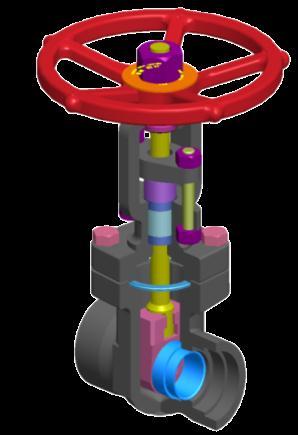
6 Exploded Views Hand wheel nut Stem Bonnet Gland Flange Hand wheel Yoke sleeve Hex Nut Stud Gland Gasket Packing Disc Cap Screw Body Seat Ring Fig. 1 Forged steel Gate Valve 6

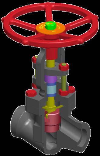
7 Hand wheel nut Stem Bonnet Gland Flange Hand wheel Yoke Sleeve Hex Nut Gland Stud Gasket Packing Disc Cap Screw Body Fig. 2 Forged steel Globe Valve 7

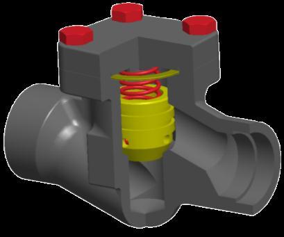
8 Cover Disc Spring Gasket Cap Screw Body Fig. 3 Forged Steel Lift Check Valve 8

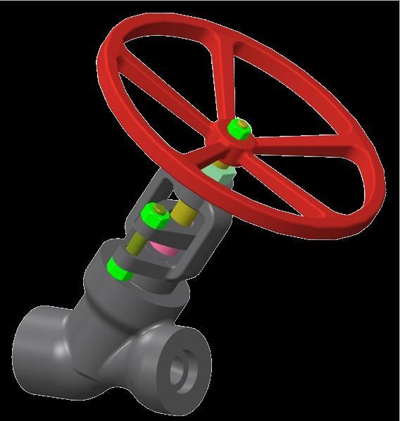
9 Hand wheel Bonnet Hand wheel nut Hex Nut Stud Stem Gland Flange Gland Bonnet Packing Gasket Disc Disc stem pin Body Fig. 4 Forged steel Y Pattern Globe Valve 9

10 Cover Spring Disc Gasket Body Fig. 5 Forged steel Y Pattern Check Valve 10


11 Lock Nut Hex Nut Hand Wheel Electric Actuator Gland Flange Stem Retainer wire Disc Washer Packing Gland Yoke Bush Bonnet Disc Adaptor Stem Bush Hex Nut Stud Body Stem Key Bonnet Fig.6 Forged Steel T-Globe Valve 11

12 Cover Spring Disc Forged Steel Lift Check Valve Body Fig.7 Forged Steel Lift Check Valve 12

13 Shipment Orientation of the valve in the packing may be either horizontal or vertical depending on the shipped valve dimensions. Please check the packing slip attached to the container before opening the same. The valves and accessories shall be examined for any damages that might have happened during transportation and handling. Valve identification details can be found on the identification plate and on the body of the valve. Typical identification plates are shown in Fig. 8, 9, 10, 11 & 12. Fig. 8 Identification Plate FS Gate Valve Fig. 9 Identification Plate FS Globe Valve Fig. 10 Identification Plate FS Check Valve Fig. 11 Identification Plate FS Y-Check Valve Fig. 12 Identification Plate FS Y-Globe Valve Valves are provided with end protectors for avoiding damage to internals. 13
14 Note: Refer Appendix B for valves with CE & ATEX certification requirements. Handling and Storage Handling Valve shall be properly supported and secured before moving, to prevent possible damage to valve, property or harm to personnel. Do not drag the valve on the ground while transporting. A minimum of one foot height from the ground is to be maintained while moving the valve. Valve shall not be slung around the valve port for transportation. For large size valves lifting lugs are provided for this purpose. The crane wire shall not be slung around the actuator to avoid any load acting on it. Also, ensure that the while handling the valve, no external load acts on the actuator. Valves shall not be handled with the hand wheel keyed. The hand wheel shall be dismantled before handling and transporting the valve. Storage Valves shall be stored in covered area which is dust free, least humid and well ventilated. Ensure that the end protectors are in place before the valve is stored, as dry contaminants like dust, sand, grit etc. can scratch metal seating surfaces and the soft parts, leading to leakage during operation. If the valve end protectors are opened for any check or testing, the same preservation and protection shall be done after the check or testing. The valve shall always be maintained in an ambience with temperature higher than the dew point temperature at the storage location, so as to avoid collection of water droplets on the valve surface. Do not keep the valve directly on the floor. Valve shall be placed on wooden pallet such that it is at least at a height of 6 inch from the floor. Care shall be exercised not to damage the extended portion of the adaptor, actuator while storage. Do not apply tar, grease or any other material inside the valve, as it could impair the performance of the valve. Improper storage and /or handling may cause disc/seal damage or deformation of shaft or seat, which will affect sealing and operational performance of the valve. 14
15 Planning & Responsibilities When installing or maintaining valves Conduct a risk assessment and eliminate or reduce hazards to an acceptable level. Work in accordance with safe systems of work site. Observe all site health and safety rules. Wear all necessary personal protective equipment. Never use a valve on a duty which exceeds its prescribed operating parameters. Refer to L&T Valves for further information. The valve shall not be subjected to frequently occurring disturbances. End user to ensure there are no external disturbances (e.g. Shocks, vibrations, electromagnetic fields etc.). Misuse of valves / valve components shall be avoided. Maximum surface temperature of the equipment will be same as the line media temperature. The end user must take account of the line media temperature. If the processes or environment that the valves are used in are likely to cause temperatures (high or low) that may cause injury to personnel if touched, then adequate insulation / protection must be fitted. Adequate safety measures shall be made for valves similar to pipe lines. Due to variety of duties in which these valves can be employed, it is the end user s responsibility to ensure the compatibility of media with the material of construction of the product for each specific application (i.e. corrosion and erosion which may affect integrity of the pressure containing envelope). Before valves are installed in areas which may be subject to seismic activity or extreme climatic conditions, consult L&T Valves with data. All exposed parts shall be cleaned to prevent dust deposit or insulation is needed similar to pipe line. Valves shall be protected by other devices to prevent over-pressurisation. (i.e., caused by temperature, fire etc.). 15
16 Valve Installation General Carefully unpack the valve and check for identification plates or tags etc. It is recommended to install Gate and Globe valves with stem vertical up. For other orientations of stem, consult factory. The performance of the valve will be better if the flow is smooth. It is suggested to avoid installation of valves where turbulence is expected (Example: Immediate after elbows, bends, pumps etc.) It is recommended to install check valves at a distance equal to 10 times or more the pipe diameter from the upstream elbows for better performance. If the identification plate / arrow plate / tag is lost or destroyed during the shipment or while in storage or if it is not legible, contact your distributor or L&T Valves. Look for any special warning tags or plate attached to or accompanying the valve and if any, take appropriate action. Some of the valves may be uni-directional, it shall be ensured that the valves are installed in the direction as marked in the body (Example: Check valves, Gate valves with cavity relief hole in disc, Cryogenic gate valves etc.). It is recommended to remove all foreign particles from the pipe line by flushing it with a suitable fluid. Corrosion inhibitors shall be added to the flushing medium to prevent any corrosion due to trapped fluids. Remove the end protectors and protective sheath within the flow bore valve, wherever provided. Gasket contact faces of the valve and pipe flanges shall be inspected thoroughly for scratches / defects. Scratches, if any, shall be corrected by grinding the surfaces or by rubbing with emery sheet. After cleaning, operate the valve for at least two complete cycles before installing. Ensure that the valve is in fully closed position during installation The pipes/flanges shall be properly aligned and provisions made to minimize stresses from external load/thermal expansion. Always review pipe manufacturer s recommendation. In case of pipes with long overhangs, adequate support/jacks shall be provided at the flange ends of the pipe so as to avoid bending of pipes due to weight of the valve. The fasteners on the valves might have loosened or relaxed during transportation or long storage. It is highly recommended that all fasteners (Body-bonnet/cover joint, yoke, gland, actuator) shall be retightened to the required torque provided in appendix A. The improper alignment of the pipe and the valve during installation can lead to unbalanced tightening of the flanges which may cause excessive stress on the flanges and bolts and lead to leakage. 16
17 Screwed Ends Refer Appendix A1 for applicable standards Check the threads on both the valve and the mating pipe for thread form and cleanliness. Check for any indication of an impact that might have deformed the thread either out-of-round or by a local indentation. Ensure no chips or grit is present. Threaded pipe joints depend on a good fit between the external and internal pipe threads for tight sealing. Apply an appropriate thread tape or thread compound to the external pipe threads except when dry seal threading is specified. Avoid getting the thread tape or thread compound into the internal flow area. Because there is no clear limit on the torque that may be developed in a tapered thread joint, it is possible to damage the valves or piping by applying excessive twisting forces through the body of the valve. If at all possible a wrench should be used on the same end of the valve to which the pipe is being threaded into. Socket and Butt welding Ends The valves provided with socket-welding ends preparation are as per standard ASME B16.11 or as per customer requirements. Please refer to the general assembly drawings for the exact socket-welding ends dimensions. The valves provided with butt-welding ends preparation are as per standard ASME B16.25 or as per customer requirements. Please refer to the general assembly drawings for the exact buttwelding ends dimensions. When welding socket weld end valves, be sure to leave 1.6 mm gap between end of pipe and bottom of valve socket. The welding of valves onto the pipeline shall be performed by qualified welders using qualified procedures. Valves shall be kept in the closed position during welding. As the valves are of small size and the sealing surfaces are close to the weld ends, care shall be taken to ensure that there is no excessive heat input/ temperature increase Care shall be taken to avoid weld spatter from falling onto the seating surfaces to prevent damage and maintain sealing effect between the metallic contacts. Local post weld heat treatment (PWHT) on the weld and heat affected zone (HAZ) shall be carried out if required by the procedure. It is recommended that the pipeline be flushed again after welding to avoid damage to disc and seat(s). The valve shall be kept fully open during flushing. After flushing is completed, operate the valve three times and ensure that it is smooth. It is recommended to carry out pressure testing of the joints. 17
18 Flanged Ends Refer Appendix A1 for applicable standards Clean valve flanges and companion flanges and remove protective grease from the valve flanges. Clean the valve interiors adjacent piping priors to mounting of the valve pipe joint. Align the bolt holes of the valve end flange and pipe flange. Fasteners shall be lubricated for ease of installation Insert the gasket (not supplied with valve) and tighten the fasteners. Flange fasteners shall be tightened evenly. Using suitable device, in cross rotation to prevent damage to the flange. For sequence of tightening fasteners, refer Appendix A2 If valve is not cleaned or if cleaning is done after valve installation, cavities may form a natural trap in the piping system. Any impurity not dissolved or washed out by the flushing fluid/line fluid may settle in such cavities and adversely affect valve performance. 18

19 Valve Operation General Operational life of the valve can be maximized if the valve is used within the rated range, in accordance with design parameters. For understanding the internal construction refer to the catalogue and general assembly drawing of the valve. Operation Mechanism Gate and Globe valve opening/closing is achieved using Hand wheel / Electrical/ Hydraulic/ Pneumatic Actuator. Hand wheel Hand wheel are provided on valves for easier operation. Clockwise operation is for closing and anticlockwise for opening of the valve (Fig. 13). Electric Actuator Fig. 13 Forcing the hand wheel, Chain wheel against the stops will not provide tighter shutoff of the valve and may damage the valve. It gives multi-turn output and is directly mounted on valve. The actuator drives the stem nut and because of this Gate / Globe valve stem travels linearly. Electrically actuated valves are provided with declutching mechanism for manual operation of the valve. For electric actuators, L&T Valves recommends to strictly adhere to the instructions as per actuator s manual. Actuator settings are done at factory and normally resetting at site will not be required. In Gate and Globe valves, electrically actuated valves shall be set as below: Open Close : Position : Torque Pneumatic / Hydraulic Actuator Pneumatic/hydraulic actuators are fitted directly on the valve. It is recommended to strictly adhere to the instructions as per actuator manual. In case, valves are supplied as bare stem, as per customer requirement, ensure that connecting devices for actuators do not exert any axial or radial loads on the valve stem, as it may lead to bending of the stem and excessive loading on the disc. This in turn can cause the torque to increase and may lead to problem in valve operation Do s and Don ts 19
20 Do s Before taking valve for erection, make sure that is cleaned properly from inside and outside and there are no foreign particles or metallic chips sticking on to sealing element. Don ts Do not lift the valve by the hand wheel, actuator or bypass arrangement. While installing the operating mechanism, make sure that the valve is in fully closed position. DO NOT use the lifting points located on the actuator, if any, to lift the valve. These lifting points are for the actuator only. Make sure to remove the entire rust preventive on the machined surface in the flow area before a valve is put in the pipe line. DO NOT over-tighten packing gland nuts. Overtightening will increase the torque required to operate the valve. Carefully read the identification plate details and install the valve in the right place and for the correct duty conditions for which it is designed and manufactured. Gate with pressure relief arrangement, Globe and Check valves have preferred sealing direction marked by an arrow on the valve body beneath the identification plate. DO NOT use impacting devices to tighten up the bolting on the body/bonnet (cover). Use suitable mechanical devices for tightening. Make sure to supply rated voltage and frequency to the electrical actuator. Do not tighten the body/bonnet nuts when the disc is in the fully closed position. DO NOT keep the Gate valves in partial open condition to regulate flow. 20
21 Maintenance Introduction For enhanced life of the valve and better operability, it is recommended to do a periodic inspection and maintenance of the valves as per the procedure explained below: The frequency of observation depends on its application. L&T Valves recommends that valve shall be inspected every 50 cycles or three months (whichever earlier) for smooth operation and leak free performance. This is recommended even for stored valves also. It is advisable to maintain a record of the performance of the valve. Safety Procedure Always depressurize the pipeline when taking up any maintenance activity on the valve/ actuator. Always disconnect the electrical supply to the electrical actuator before carrying out any maintenance activity on the valve/actuator. Study carefully and understand the instructions outlined in the installation, operation & maintenance manual of the valve & actuator before taking up any maintenance. Routine Maintenance The following activities can be carried out during the routine maintenance of the valves. 1. Gland Leak Check the tightness of the gland eye bolts and tighten evenly if required. If the leak persists, the packing shall be renewed. The pipeline shall be shut off so that there is no pressure inside the valve before the gland eye bolts are loosened. Caution: Do not replace gland packing when the line is under pressure. Most of the packing rings are already cut so that they can be inserted around the stem. In case of solid moulded packing like graphite rings, use a sharp knife and cut the rings at 30 angle. Then slightly twist the ring and insert it around the stem. Do not open up the ring as it could break. 2. Body Bonnet/Cover joint leak Check the tightness of the bolting and tighten the bolts at the vicinity of the leak. If the leak still persists, renew the gasket. The section of the pipe shall be shut off to ensure no pressure is trapped in the line, before dismantling the bonnet. Spirally wound stainless steel with graphite filler gaskets is used. 3. Lubrication Grease the stem threads and Yoke sleeve in Gate and Globe valves regularly (Grease: Copper gel or equivalent). 4. Hot Torque For the valves which are used at high temperature application, it is recommended to retighten the flange bolts after one month of operation to avoid the leak through joints. 21


. Care shall be taken not to drop the gate/disc while lifting out.")
22 Dismantling and Assembly Procedure Dismantling Procedure All valves are designed to permit inspection without removing the body from the pipeline. The section of the pipe shall be shut off to ensure no pressure is trapped in the line, before dismantling the valve for inspection. Gate and Globe valves can be inspected by removing the bonnet assembly. However, the valves shall be kept in fully open or partially open position to relieve body cavity pressure before removing the bonnet assembly. Check valves can be inspected by removing the cover assembly. In case of Check valve, there is no stem and hence only the cover is to be removed. The disc is inside the body. For ease of illustration only the word bonnet is used below in the dismantling and reassembly procedure. This may be changed to read as cover with respect to Check valves. Keep the valve in mid position and remove the hand wheel / actuator from the top of the valve (Fig. 14). Loosen the body-bonnet bolting and remove the cap screw. Lift the bonnet assembly including stem and disc out of the body (Fig. 15). Care shall be taken not to drop the gate/disc while lifting out. Mark the matching surfaces of the gate and body seat rings of Gate valves so that they are not interchanged during assembly. Remove the bonnet gasket. Carry out the required replacement of the parts and reassemble the valve with new parts For actuator orientation change, refer Appendix A3. Fig. 14 Fig
23 Assembly Procedure Place the gasket on body correctly. It is recommended to use fresh gasket. Lower the bonnet assembly including the disc smoothly into the body, keeping the disc in open position. Remember to match the marking done earlier on disc and body seat rings. A blue bearing test will confirm if there is a uniform contact between disc and body seat rings. If required replace the gland packing, tighten the bolt as per torque given in Table 2. Fit the bonnet studs and tighten the nuts as per torque figures shown in Table 1, evenly working at diagonally opposite pairs. Do not over tighten as the gasket may get damaged. Assemble the Hand wheel. Operate the valve from fully closed to fully open position manually and ensure smooth operation. Troubleshooting Problem Reason Action Valve Leaking Valve not closed fully Valve seating damage Re-tighten the handwheel Dismantle and lap the seating Leakage through Gland Packing loosened Packing worn out Tighten the gland Replace the packing Leakage through Bonnet / Cover joint Bonnet / Cover bolting loose Gasket damage Tighten the bolting Dismantle and replace the gasket Not closing fully Debris inside the valve Clean the pipeline 23
24 Appendix A A1 - References Face to Face Dimensions ASME B16.10 Face-to-Face and End-to-End Dimensions of Valves End Connections ASME B16.5 Pipe Flanges and Flange Fittings (NPS ½ through NPS 24) ASME B16.11 Forged Fittings, Socket-Welding and Threaded ends. ASME B16.25 Buttwelding ends ASME B Pipe thread, general purpose Testing Standard API 598 EN12266 PART-1 Valve Inspection and Testing Industrial Valves Testing Of Valve A2 - Tightening Sequence & Torque The tightening sequence for all possible number of bolting, the logic to be followed is explained below: Tighten the first four nuts in the sequence shown Fig.16. This helps in correct location of the mating parts. Ensure that the recommended torque (refer Table1 & 2) is maintained in all bolting. Fig. 16 Sequence of Tightening 24
25 Table 1 Tightening Torque TORQUE, Nm THREAD SIZE, inch-tpi B7/B7M/B16/L7/L7M/ L43/660 Cl.A/UNS N07718/UNS B8 Cl.2/B8C Cl.2/ B8M Cl.2/B8T Cl.2/ XM-19 UNS N06625 Gr 1 1/4-20 UNC /16-18 UNC /8-16 UNC /16-14 UNC /2-13 UNC /16-12 UNC /8-11 UNC /4-10 UNC /8-9 UNC UNC /8-8 UN lbf.ft = Nm / Table 2 Gland Tightening Torque VALVE SIZE GATE VALVES TORQUE, Nm CLASS GLOBE VALVES 800 (RP) 800 (FP) (RP) 800 (FP) /4" /8" /2" /4" " /4 & 1.1/2 " " lbf.ft = Nm / RP- Reduced port FP- Full port 25
26 A3 Actuator Reorientation Procedure: Actuator orientation change procedure is given below, Depressurize the line and keep the valve in half open position. Remove actuator bottom screws. Rotate the actuator and change orientation to required position, match holes in the yoke to that of the actuator. Insert the bottom screws & tighten to required torque. Operate the valve 2 to 3 times before pressurizing line. In order to dismount actuator from valve, after unscrewing the bottom screws of yoke, lift the actuator slightly and rotate it for few turns in counter-clock wise direction so as to remove the stem from actuator bush. Thus actuator can be dismounted from valve. (Fig.17) Fig. 17 Appendix B For valves with CE & ATEX certification requirements Each valve has a stainless steel Identification plate fixed to the body. The Identification plate is marked with details of "catalogue number", along with various other details such as the materials of construction, Limiting temperatures, pressure rating as shown below According to PED 97/23/EC Fig.B.1. CE Marking Identification Plate 26
 D = Dust zone suitability (Zones 21 & 22) c = Type of")
27 Fig.B.2. ATEX Name Plate Definition of name plate marking above: II = Equipment group 2 = Equipment category G = Gas zone suitability (Zones 1 & 2) D = Dust zone suitability (Zones 21 & 22) c = Type of protection (i.e.) constructional safety (EN ) X = Special conditions (EN ). Special Condition: X Surface temperature: As per EN :2001(E) paragraph 14.2.g, the temperature class or maximum surface temperature cannot be marked on the product as it is dependent on the operating conditions. However the maximum allowable operating temperature for the product is marked on the identification plate. Material tractability markings are hard marked on the valve body CAUTIONARY NOTES When installing or maintaining valves Observation shall be made for safety codes and working practices relevant to gas zones 1 & 2 and dust zones 21 & 22 (as defined in EN :1998). The equipment shall not be subjected to frequently occurring disturbances. End user to ensure there is no external disturbances (e.g. Shocks, vibrations, electromagnetic fields etc.) Misuse of valves / valve components are strictly prohibited. If the processes or environments that the products are used in are likely to cause temperatures (high or low) that may cause injury to personnel if touched, then adequate insulation / protection must be fitted. 27
28 Adequate safety measures shall be made for valves similar to pipe lines. Before equipment is installed in areas which may be subject to seismic activity or extreme climatic conditions consult L&T Valves with data. Maximum surface temperature of the equipment will be same as the line media temperature. The end user must take account of the line media temperature. All exposed parts shall be cleaned to prevent dust deposit or insulation is needed similar to pipe line. This equipment should be protected by other devices to prevent over-pressurization. (i.e. caused by external fire etc.). End user to ensure that the accessories (actuator, limit switches, solenoid valve, etc.) if fitted with valve are of ATEX qualified as per the directive. Valves are not suitable for terminal connections. In such cases, valves shall be fitted with blind flanges. 28
29 Document Number: LTV-565-R0/0614 As we continuously endeavor to improve our products, the data given herein is subject to change. Please refer for the latest IOM. 29
Installation, Operation and Maintenance Manual of Triple Offset Butterfly Valves
 Installation, Operation and Maintenance Manual of Triple Offset Butterfly Valves Contents P.No. L&T Valves 3 Triple Offset Butterfly Valves 4 Exploded View 5 Delivery 6 Handling and Storage 7 Planning
Installation, Operation and Maintenance Manual of Pressure Seal Gate, Globe & Check Valves
 Installation, Operation and Maintenance Manual of Pressure Seal Gate, Globe & Check Valves Contents Page No. L&T Valves 3 Pressure Seal Gate, Globe & Check Valves 4, 5 Exploded View 6, 7, 8, 9 Delivery
Installation, Operation and Maintenance Manual of Pressure Seal Gate, Globe & Check Valves
 Installation, Operation and Maintenance Manual of Pressure Seal Gate, Globe & Check Valves Contents Page L&T Valves 3 Pressure Seal Bonnet Valves 4 Exploded Views 6 Delivery 12 Handling and Storage 13
Installation, Operation and Maintenance Manual for AlL Pressure seal Bonnet/Cover Class 600, 900, 1500 & 2500 Cast steel Gate, Globe & Check Valves
 Installation, Operation and Maintenance Manual for AlL Pressure seal Bonnet/Cover Class 600, 900, 1500 & 2500 Cast steel Gate, Globe & Check Valves AUDCO INDIA LIMITED Chennai India AIL REF. No: IOM/PS/001
Installation, Operation, and Maintenance Manual Full Port Y-Pattern, Bolted Bonnet, Globe and Check Valves
 SMITH VALVES Installation, Operation, and Maintenance Manual Full Port Y-Pattern, Bolted Bonnet, Globe and Check Valves Globe Valve Series: YG80/YG15 Welded Bonnet Globe Valve Series: YG87/YG17 Piston
When installing the screwed end, socket weld & flanged end valves the following respective procedures shall be followed for better performance.
 1. Storage LARSEN & TOUBRO LIMITED Page 1 of 5 1.1. All valves are to be stored in fully open position, in order to protect the sphere surface and soft valve seats. 1.2. Before shipping, the inlet and
Bolted Bonnet Gate Valves. Installation, Operation & Maintenance Manual
 Installation, Operation & Maintenance Manual Bolted Bonnet Gate Valves L&T Valves Valve Manufacturing Unit Larsen & Toubro Limited L&T Campus, Malumichampatti Coimbatore 641050 Tamil Nadu India Table of
GT-200 GATE VALVES PN16, Screwed end
 Document No. : MD-QO-04-281 Date : 2009/07 /17 Version : 1.0 GT-200 GATE VALVES PN16, Screwed end USER MANUAL Modentic Industrial Corporation 14F-1,No.57Taya Rd.,Taichung,Taiwan,R.O.C. Email:modentic@ms9.hinet.net
Double Block & Bleed Plug Valves
 Double Block & Bleed Plug Valves ASME Class 150 & 300 50 mm to 750 mm (2 to 30 ) API 6D L&T Valves L&T Valves Limited (Formerly Audco India Limited) is a wholly owned subsidiary of Larsen & Toubro. Backed
Double Block and Bleed Plug Valves
 Double Block and Bleed Plug Valves ASME Class 150 to 600 50 mm to 1050 mm (2 to 42 ) API 6D L&T Valves L&T Valves is a wholly owned subsidiary of Larsen & Toubro. Backed by a heritage of excellence that
Operating & Maintenance Manual For Steam Conditioning Valve
 For Steam Conditioning Valve 1 Table of Contents 1.0 Introduction 3 2.0 Product description 3 3.0 Safety Instruction 4 4.0 Installation and Commissioning 5 5.0 Valve Disassembly 6 6.0 Maintenance 6 7.0
INSTALLATION, OPERATION, MAINTENANCE MANUAL FOR MANUALLY OPERATED STOP CHECK VALVE
 INSTALLATION, OPERATION, MAINTENANCE MANUAL FOR MANUALLY OPERATED STOP CHECK VALVE Page 1 of 13 1.1 General CHAPTER 1 - GENERAL INFORMATION This manual contains maintenance instructions with pertinent
Installation, Operation, and Maintenance Manual. Gate, Globe, and Check Valves
 SMITH VALVES Installation, Operation, and Maintenance Manual Gate, Globe, and Check Valves TNC Doc EDC 303, Revision 7, Issued November 2013 TABLE OF CONTENTS 1.0 - GENERAL 2.0 - INSTALLATION 3.0 - OPERATION
Newco / OIC / Cooper Forged Valves. Operation & Maintenance. Manual
 NEWCO / OIC / COOPER VALVES Newmans Inc., Newmans Valve Ltd. Operation & Maintenance Manual Revision 2, 9 May 2007 1. Introduction and Safety Information... 1 1.1. Introduction... 1 1.2. Safety Information...
Apollo Standard Port, Full Port & One Piece Flanged Ball Valves Installation, Operation, & Maintenance Guide
 I854000.F M16005 Apollo Standard Port, Full Port & One Piece Flanged Ball Valves Introduction This manual presents guidelines for the Installation, Operation and Maintenance of manual and automated Apollo
Installation, Operation and Maintenance Guide II NIBCO High Performance Butterfly Valves Series 6822 and 7822
 Installation, Operation and Maintenance Guide II NIBCO High Performance Butterfly Valves Series 6822 and 7822 Statements: NIBCO High Performance Butterfly Valves, Series 6822 and 7822, have been designed
KEYSTONE SERIES 320 BUTTERFLY VALVES INSTALLATION AND MAINTENANCE INSTRUCTIONS
 Before installation these instructions must be fully read and understood HAZARD POTENTIALS disregarding of instructions improper use of product insufficiently qualified personnel Valve application to be
LNG Screw Down Non-Return Valve Installation, Operation and Maintenance Manual
 Installation, Operation and Maintenance Manual Date of Issue: 04 August 2010 Page 1 of 27 QF 80: Issue 2 WARNING! BEFORE ANY INSTALLATION AND MAINTENANCE WORK CAN COMMENCE ENSURE THE VALVE AND SURROUNDING
IOM Manual. IOM Manual. Series 76/77.
 IOM Manual IOM Manual Series 76/77 www.flowlinevalves.com Flow Line Valve and Controls, L.L.C. 110 Main Project Road Schriever, LA 70395 P.O. Box 677 Schriever, LA 70395 Phone 985-414-6004 * Toll Free
Triple-offset Butterfly Valves
 Triple-offset Butterfly Valves ASME Class 150 to 1500 3 to 100 (80 mm to 2500 mm) API 609 L&T Valves L&T Valves is a wholly owned subsidiary of Larsen & Toubro. Backed by a heritage of excellence that
Danfoss Butterfly Valve
 Triple Eccentric Danfoss Butterfly Valve Operating, installation and maintenance instructions Edition 1 / January 2015. Table of Contents: 1 Overview... - 1-2 General... - 1-2.1 Safety notes... - 1-2.2
Gate, Globe & Check Valves Corrosion-resistant
 Gate, Globe & Check Valves Corrosion-resistant ASME Class 0 to 00 " - " (0 mm - 00 mm) API 0, ASME B. L&T Valves Trusted by the industry for over five decades, L&T Valves offers innovative products and
CV Control Valves Installation and Operation Manual
 CV1500 - Control Valves Installation and Operation Manual 652-EN Overview Warning: This bulletin should be used by experienced personnel as a guide to the installation of the Armstrong CV1500 Control Valve.
Mounting and Operating Instructions EB 8135/8136 EN. Series V2001 Valves Type 3535 Three-way Valve for Heat Transfer Oil
 Series V2001 Valves Type 3535 Three-way Valve for Heat Transfer Oil Type 3535 Three-way Valve with bellows seal and rod-type yoke (partial view) Mounting and Operating Instructions EB 8135/8136 EN Edition
MK Series - High Performance Butterfly Valves Operation and Maintenance Instructions
 COMMERCIAL Bray Controls Commercial Division 13788 West Road, Suite 200A Houston, Texas 77041 BCDSales@Bray.com Phone: 1-888-412-2729 Fax: 1-888-412-2720 www.braycommercialdivision.com MK Series - High
Ideal Installation. I & M Mark 67 (1/2 6 ) Control Line. Installation & Maintenance Instructions for Mark 67 Pressure Regulators
 Control Line. Installation & Maintenance Instructions for Mark 67 Pressure Regulators") I & M Mark (/ ) 0 Wasson Road Cincinnati, OH 0 USA Phone --00 Fax -8-00 info@richardsind.com www.jordanvalve.com Installation & Maintenance Instructions for Mark Pressure Regulators Warning: Jordan Valve
I & M Mark (/ ) 0 Wasson Road Cincinnati, OH 0 USA Phone --00 Fax -8-00 info@richardsind.com www.jordanvalve.com Installation & Maintenance Instructions for Mark Pressure Regulators Warning: Jordan Valve
Mounting and Operating Instructions EB 8111/8112 EN. Series V2001 Valves Type 3321 Globe Valve
 Series V2001 Valves Type 3321 Globe Valve Type 3321 Globe Valve with rod-type yoke and Type 3372 Electropneumatic Actuator (350 cm²) Mounting and Operating Instructions EB 8111/8112 EN Edition June 2013
Before installation these instructions must be fully read and understood
 Before installation these instructions must be fully read and understood Yoke bushing Split gland bushing One-piece body with accessible internals Gland Swing bolts Fully retractable stellite disc Figure
Bolted Bonnet Check Valve. Installation, Operation & Maintenance Manual
 Installation, Operation & Maintenance Manual Bolted Bonnet Check Valve L&T Valves Limited L&T Campus, Malumichampatti Coimbatore 641021 Tamil Nadu India Table of Contents 1 Introduction 1.1 Scope 2 General
IMOI 2010 Rev 0
 FOREWORD The following instructions are offered as a reference aid to the valve user when installing, maintaining or operating Williams Gate, Globe and Swing Check valves. This document, consisting of
Fisher RSS Lined Globe Valve
 Instruction Manual D0990 RSS Valve July 07 Fisher RSS Lined Globe Valve Contents Introduction... Scope of Manual... Description... Educational Services... Specifications... Installation... Maintenance...
Worcester 519 / 529 Series
 Installation, Operating & Maintenance Instructions Worcester 519 / 529 Series 15-40mm Full Bore 50mm Reduced Bore 1 STORAGE AND PRESERVATION All valves are despatched in the open position and it is recommended
Fisher TBX Hydro Plug Fixture
 Instruction Manual TBX Hydro-Plug Fixture Fisher TBX Hydro Plug Fixture Contents Introduction... 1 Scope of Manual... 1 Description... 2 Educational Services... 2 Principle of Operation... 2 Maintenance...
Fisher CVX Hydro Plug Fixture
 Instruction Manual CVX Hydro-Plug Fixture Fisher CVX Hydro Plug Fixture Contents Introduction... 1 Scope of Manual... 1 Description... 1 Educational Services... 2 Principle of Operation... 2 Maintenance...
KEYSTONE. Butterfly valves Figure 9 Installation & Maintenance Instructions. Please read these instructions carefully
 KEYSTONE Please read these instructions carefully This symbol indicates important messages and safety instructions. Hazard potentials: disregarding of instructions improper use of product insufficiently
INSTALLATION - MAINTENANCE MANUAL Severe Service Series M4 Ball Valve
 INSTALLATION - MAINTENANCE MANUAL Severe Service Series M4 Ball Valve Date: May 2016/ Page 2 of 12 Table of Contents 1. Safety Information - Definition of Terms..........................2 2. Bill of Materials....................................
Butterfly valves Figure 56 Installation & Maintenance Instructions
 KEYSTONE Please read these instructions carefully This symbol indicates important messages and safety instructions. Hazard potentials: disregarding of instructions improper use of product insufficiently
Keystone Series GR resilient seated butterfly valves GRW/GRL Installation and operation manual
 Before installation these instructions must be fully read and understood Important Before valves are installed or used the following actions are recommended. 1. Valves/parts have to be inspected and thoroughly
INSTALLATION, OPERATION & MAINTENANCE MANUAL. 0.- Description Handling Installation Actuators Maintenance...
 INSTALLATION, OPERATION & MAINTENANCE MANUAL INDEX Page 0- Description 2 1- Handling 2 2- Installation 2 3- Actuators 5 4- Maintenance 5 41- Gland packing replacement 5 42- Seal replacement 6 43- Gasket
Ball Valves. ASME Class 150 to mm mm (¼" - 8") ISO 17292/ API 6D
 ISO 17292/ API 6D") Ball Valves SM Class 150 to 2500 8 mm - 200 mm (¼" - 8") ISO 17292/ PI 6D L&T Valves Limited is a wholly owned subsidiary of Larsen & Toubro. Backed by a fifty-year track-record of excellence and world-leading
Ball Valves SM Class 150 to 2500 8 mm - 200 mm (¼" - 8") ISO 17292/ PI 6D L&T Valves Limited is a wholly owned subsidiary of Larsen & Toubro. Backed by a fifty-year track-record of excellence and world-leading
Instalation, Operation and Maintenance Manual
 POWER BALL VALVE Instalation, Operation and Maintenance Manual Rev. 1 1 of 23 INDEX PAGE 1.0 INTRODUCTION-----------------------------------------------------------------------------4 2.0 RECEIVING & PREPARATION
Baumann 24000F Wafer Control Valve
 Instruction Manual 24000F Valves Baumann 24000F Wafer Control Valve Contents Introduction... 1 Scope of Manual... 1 Safety Precautions... 2 Maintenance... 2 Installation... 3 Air Piping... 3 Disassembly...
Triple-offset Butterfly Valves
 Triple-offset Butterfly Valves ASME Class 150 to 1500 3 to 100 (80 mm to 2500 mm) API 609 L&T Valves Triple-offset Butterfly Valves L&T Valves is a wholly owned subsidiary of Larsen & Toubro. Backed by
McCannalok HIGH PERFORMANCE BUTTERFLY VALVE OPERATION AND MAINTENANCE MANUAL. The High Performance Company
 McCannalok HIGH PERFORMANCE BUTTERFLY VALVE OPERATION AND MAINTENANCE MANUAL The High Performance Company Table of Contents Safety Information - Definition of Terms... 1 Introduction... 1 Installation...
Mounting and Operating Instructions EB 8053 EN. Series 250 Type and Type Pneumatic Control Valves
 Series 250 Type 3252 1 and Type 3252 7 Pneumatic Control Valves Type 3252 High-pressure valve with Type 3277 Pneumatic Actuator and Type 3767 Electropneumatic Positioner Mounting and Operating Instructions
Butterfly Valve Type 57P
 Butterfly Valve Type 57P Contents Lever Type: 50-200 mm (2-8 ) Body Material: CPVC Gear Type: 50-200mm (2-8 ) Body Material: CPVC (1) Be sure to read the following warranty clauses of our product 1 (2)
5000/6000 SERIES BALL VALVES INSTALLATION - MAINTENANCE MANUAL
 Date: August 2011 / Page 1 of 6 5000/6000 SERIES BALL VALVES INSTALLATION - MAINTENANCE MANUAL DESIGN The design features three piece construction and a free floating ball allowing ease of maintenance
Instructions for installation, operation and maintenance of: GATE VALVE
 Instructions for installation, operation and maintenance of: GATE VALVE GEN GAC GAF/GENF TERMOVENT SC Temerin Republic of Serbia Instruction for installation, operation and maintenance: Table of Contents
DOUBLE OFFSET BUTTERFLY VALVE
 Flange STD: ASME CLASS 150 LB ASME CLASS 300 LB Temp :210 ~29 Work pressure: VF-91_/92_/93_ 2 ~48 150LB VF-94_/95_/96_ 2 ~24 300LB Pd. date 2011.5 Please read all of these instructions before installing
Baumann Way Control Valve
 Instruction Manual 24003 Valve Baumann 24003 3-Way Control Valve Contents Introduction... 1 Scope of Manual... 1 Safety Precautions... 2 Educational Services... 3 Maintenance... 3 Installation... 3 Air
Baumann 24000C Carbon Steel Little Scotty Control Valve Instructions
 Instruction Manual D103356X012 24000C Control Valve Baumann 24000C Carbon Steel Little Scotty Control Valve Instructions CONTENTS Introduction...1 Scope...1 Safety Precautions...1 Maintenance...2 Flow
Double Offset High Performance Butterfly Valve
 Double Offset High Performance Butterfly Valve INSTALLATION OPERATION MAINTENANCE APOLLO INTERNATIONAL HIGH PERFORMANCE BFV IOM - Page 2 of 20 TABLE OF CONTENTS INTRODUCTION 3 PRODUCT STORAGE 3 PRODUCT
Installation, Operation and Maintenance Manual
 Installation, Operation and Maintenance Manual for the irsvp Metal Seated Ball Valve ASME Class 1500 / 3100 / 4500 PREPARE THE VALVE FOR INSTALLATION INSTALL THE VALVE PROPERLY STRESS RELIEVE WELDS ACCORDING
MERIDIAN, 2 or 3 PIECE, TRUNNION MOUNTED BALL VALVES
 INSTALLATION, OPERATION AND MAINTENANCE INSTRUCTIONS MERIDIAN, 2 or 3 PIECE, TRUNNION MOUNTED BALL VALVES Size Range 2 48 ASME Classes 150-2500 *It is recommended that the valve installer is familiar with
Bray/Mckannalok Butterfly Valve Series 40/41/42/43/44/45 Installation Manual Technical Bulletin No Date: May 2004/Page 1 of 6
 Date: May 2004/Page 1 of 6 Bray/McCannalok Butterfly Valves Installation and Maintenance Instructions ANSI Classes 150 and 300 - Sizes 2-1/2 through 24 ANSI Classes 600 - Sizes 3 through 16 Bidirectional
CompoSeal butterfly valves, wafer style Installation & Maintenance Instructions
 Please read these instructions carefully This symbol indicates important messages and safety instructions. Intended valve use The valve is intended to be used only in applications within the pressure/temperature
Operating Guide SBFV (PN16/25) ENGLISH Steel butterfly valve SBFV Page 2. Danfoss VI.IX.A1.02 1
 ENGLISH Steel butterfly valve SBFV Page 2. Danfoss VI.IX.A1.02 1") Operating Guide SBFV (PN16/25) ENGLISH Steel butterfly valve SBFV www.danfoss.com Page 2 Danfoss 2016.06 VI.IX.A1.02 1 Table of Contents: 1. OVERVIEW... 3 2. GENERAL... 3 2.1 Safety...3 2.2 Proper use...4
Operating Guide SBFV (PN16/25) ENGLISH Steel butterfly valve SBFV www.danfoss.com Page 2 Danfoss 2016.06 VI.IX.A1.02 1 Table of Contents: 1. OVERVIEW... 3 2. GENERAL... 3 2.1 Safety...3 2.2 Proper use...4
2001 SERIES CRYOGENIC BAR STOCK BODY VALVES
 12501 Telecom Drive, Tampa, FL 33637 Ph: (813) 978-1000 Fax: (813) 977-3329 www.cpc-cryolab.com INSTALLATION, OPERATING, AND MAINTENANCE INSTRUCTIONS 17/4.5.2 Rev. 0 2001 SERIES CRYOGENIC BAR STOCK BODY
MAINTENANCE GUIDELINES FOR NIBCO 2" THROUGH 10" CLASS 125, 150 & 250
 NIBCO INC. WORLD HEADQUARTERS 1516 MIDDLEBURY ST. ELKHART, IN 46516-4740 USA PHONE: 574.295.3000 FAX: 574.295.3307 WEB: www.nibco.com INSTALLATION, OPERATION & MAINTENANCE INSTRUCTIONS MAINTENANCE GUIDELINES
Installation, Operating & Maintenance Instructions. Worcester 18 / 19 Series Multiway Valves
 Installation, Operating & Maintenance Instructions Worcester 18 / 19 Series Multiway Valves 1 STORAGE AND PRESERVATION All valves are despatched in the open position and it is recommended that they are
PFA LINED BALL VALVES Installation, Operation and Maintenance Manual
 ACRIS PFA LINED BALL VALVES WWW.AMRESIST.COM Table of Contents Safety Instructions - Definition of Terms............................................2 Introduction..............................................................2
Baumann Little Scotty Bronze Control Valve
 Instruction Manual 24000 Valve Baumann 24000 Little Scotty Bronze Control Valve Contents Introduction... 1 Scope of Manual... 1 Safety Precautions... 2 Maintenance... 2 Installation... 3 Air Piping...
Fisher RSS Lined Globe Valve
 Instruction Manual D0990 November 009 RSS Valve Fisher RSS Lined Globe Valve Contents Introduction............................... Scope of Manual.......................... Description...............................
Model DF233 Control Valve
 Figure 1 DF233 Control Valve TABLE OF CONTENTS Introduction 2 Body and Packing Reassembly 7 Specifications 3 Fail Closed Actuator Reassembly 8 Valve Sizes 3 Fail Open Actuator Reassembly 9 Unpacking 4
USER INSTRUCTIONS. NAF Trunnball DL Ball Valves. Installation Operation Maintenance. Experience In Motion FCD NFENIM A4 01/15
 USER INSTRUCTIONS NAF Trunnball DL Ball Valves FCD NFENIM4168-01-A4 01/15 Installation Operation Maintenance Experience In Motion Contents SAFETY 3 1 General 3 2 Lifting 4 3 Receiving Inspection 4 4 Installation
Installation, Operation and Maintenance Manual for the HE Series
 Installation, Operation and Maintenance Manual for the HE Series High Performance Butterfly Valve "Double Offset" CONTENT IOM-HP-100614-1 1. INTRODUCTION 1.1 GENERAL NOTE 1.2 STRUCTURE & TYPE 1.3 OPERATION
Model DF269 Control Valve
 Figure 1 DF269 Control Valve TABLE OF CONTENTS Introduction 2 Fail Open Actuator Disassembly 6 General 2 Body and Packing Reassembly 7 Scope 2 Fail Closed Actuator Resassembly 8 Specifications 3 Fail Open
DeZURIK " BAW AWWA BUTTERFLY VALVES WITH EPOXY-RETAINED SEAT
 DeZURIK 20 144" BAW AWWA BUTTERFLY VALVES WITH EPOXY-RETAINED SEAT Instruction D10373 April 2017 Instructions These instructions provide information about the 20 (250 F2 model only) and the 24-144 BAW
Ver Trunnion Ball Valve INSTALLATION, OPERATION AND MAINTENANCE MANUAL FBV/IOM/BA02
 Ver. 2008 Trunnion Ball Valve INSTALLATION, OPERATION AND MAINTENANCE MANUAL FBV/IOM/BA02 TABLE OF CONTENTS 1 APPLICATIONS...2 1.1 Applications...2 1.2 Performance Specifications...2 2 APPLICABLE STANDARDS...2
NIBCO INC. WORLD HEADQUARTERS INSTALLATION, OPERATION & MAINTENANCE INSTRUCTIONS
 NIBCO INC. WORLD HEADQUARTERS 1516 MIDDLEBURY ST. ELKHART, IN 46516-4740 USA PHONE: 574.295.3000 FAX: 574.295.3307 WEB: www.nibco.com INSTALLATION, OPERATION & MAINTENANCE INSTRUCTIONS Installation and
Crispin Valves Operating Guide. Crispin
 Crispin Valves Operating Guide Crispin Since 1905 Crispin Multiplex Manufacturing Co. 600 Fowler Avenue Berwick, PA 18603 1-800-AIR-VALV T: (570) 752-4524 F: (570) 752-4962 www.crispinvalve.com sales@crispinvalve.com
INSTALLATION & MAINTENANCE MODEL mm
 MODEL 65-25mm INSTALLATION INSTRUCTIONS CAUTION: Installation of Backflow Preventers must be performed by qualified, licensed personnel. The installer should be sure the proper device has been selected
I & M Mark 708ME. Ideal Installation. Start-Up Procedure. Installation & Maintenance Instructions for Mark 708 & Motor Actuator
 I & M Mark 708ME 3170 Wasson Road Cincinnati, OH 45209 USA Phone 513-533-5600 Fax 513-871-0105 info@richardsind.com www.lowfl owvalve.com Installation & Maintenance Instructions for Mark 708 & Motor Actuator
Installation and Maintenance Guidelines for. NIBCO Cast Iron, Alloy Iron and Ductile Iron Gate Valves 2 to 24 Class 125, 150, 175 and 250
 INSTALLATION, OPERATION & MAINTENANCE INSTRUCTIONS Installation and Maintenance Guidelines for Review Date: 01/18/2012 Original Date: NA NIBCO Cast Iron, Alloy Iron and Ductile Iron Gate Valves 2 to 24
COMMERCIAL. BV & BVM Series Installation Instructions 06/29/15
 COMMERCIAL Bray Controls Commercial Division 13788 West Road, Suite 00A Houston, Texas 77041 BCDSales@Bray.com Phone: 1-888-41-79 Fax: 1-888-41-70 www.braycommercialdivision.com BV & BVM Series Installation
Mounting and Operating Instructions EB 8039 EN. Type 3351 Pneumatic On/off Valve. Type 3351 Pneumatic On/off Valve. Type 3351 Pneumatic On/off Valve
 Type 3351 Pneumatic On/off Valve Type 3351 Pneumatic On/off Valve Type 3351 Pneumatic On/off Valve Version with handwheel Mounting and Operating Instructions EB 8039 EN Edition May 2016 Definition of signal
Fisher D2T FloPro Control Valve
 Instruction Manual D2T FloPro Valve Fisher D2T FloPro Control Valve Contents Introduction... 1 Scope of Manual... 1 Description... 1 Educational Services... 2 Specifications... 3 Installation... 3 Setting
Scope. Applicability. Caution. I & M CV3000 Series. Storage. Installation & Maintenance Instructions for Marwin CV3000 Series Three Piece Ball Valves
 I & M CV3000 Series 3170 Wasson Road Cincinnati, OH 45209 USA Phone 513-533-5600 Fax 513-871-0105 marwin@richardsind.com www.marwinvalve.com Installation & Maintenance Instructions for Marwin CV3000 Series
Installation, Operation and Maintenance Manual
 Installation, Operation and Maintenance Manual for the MOGAS ISOLATOR 2.0 Floating Ball Valve 1, 1.5, 2, 3 and 4 inch PREPARE THE VALVE FOR INSTALLATION INSTALL THE VALVE PROPERLY MAINTAIN THE VALVE FOR
HIGH PRESSURE CONTROL VALVE PISTON BALANCED
 PISTON BALANCED All Rights Reserved. All contents of this publication including illustrations are believed to be reliable. And while efforts have been made to ensure their accuracy, they are not to be
KEYSTONE SERIES GRF RESILIENT SEATED BUTTERFLY VALVES INSTALLATION AND OPERATION MANUAL
 Before installation these instructions must be fully read and understood Intended valve use The valve is intended to be used only in applications within the pressure/temperature limits indicated in the
Installation, Operation, and Maintenance Manual GENERAL VALVE GENERAL VALVE TRUSEAL / IOM-GEN-TRUSEAL. Installation, Operation, and Maintenance Manual
 Installation, Operation, and Maintenance Manual GENERAL T GENERAL VALVE Installation, Operation, and Maintenance Manual Cameron s Valves & Measurement Group Revised 10/07 IOM-GEN-TRUSEAL Installation,
EC4 SERIES CRYOGENIC VALVES 1/4 2 Sizes
 12501 Telecom Drive, Tampa, FL 33637 Ph: (813) 978-1000 Fax: (813) 977-3329 www.cpc-cryolab.com INSTALLATION, OPERATING, AND MAINTENANCE INSTRUCTIONS 17/2.5.6 Rev. 0 EC4 SERIES CRYOGENIC VALVES 1/4 2 Sizes
TRITEC (TT2) Instruction Manual
 Instruction Manual") 1/9 TRITEC (TT2) Instruction Manual 1. Introduction P2 2. Features of Triple Offset Valve (Torque Sealing) P2 3. Standard Specifications P2 4. Handling Procedure 4.1 Packaging P3 4.2 Transportation Conditions
1/9 TRITEC (TT2) Instruction Manual 1. Introduction P2 2. Features of Triple Offset Valve (Torque Sealing) P2 3. Standard Specifications P2 4. Handling Procedure 4.1 Packaging P3 4.2 Transportation Conditions
Mounting and Operating Instructions EB 8091 EN. Pneumatic Control Valve Type and Type Type with 120 cm 2 actuator
 Pneumatic Control Valve Type 3510-1 and Type 3510-7 Type 3510-1 with 120 cm 2 actuator Type 3510-7 with 120 cm 2 actuator and integrated positioner Type 3510-1 with 60 cm 2 actuator Fig. 1 Pneumatic control
GATE VALVES. Type P (Standard: Plug) Type S (Soft Seal) Contents. (1) Be sure to read the following warranty clauses of our product 1
 Type S (Soft Seal) Contents. (1) Be sure to read the following warranty clauses of our product 1") Serial No. H-V011-E-12 GATE VALVES Type P (Standard: Plug) Type S (Soft Seal) Contents (1) Be sure to read the following warranty clauses of our product 1 User s Manual (2) General operating instructions
Serial No. H-V011-E-12 GATE VALVES Type P (Standard: Plug) Type S (Soft Seal) Contents (1) Be sure to read the following warranty clauses of our product 1 User s Manual (2) General operating instructions
Keystone Butterfly valves ParaSeal Installation and maintenance instructions
 Before installation these instructions must be fully read and understood Please read these instructions carefully Hazard potentials: disregarding of instructions improper use of product insufficiently
IMO-200EN 09/2010. Trunnion mounted forged ball valves Model FF and GG. Installation, Maintenance and Operating Instructions IMO-200EN 09/2010
 IMO-200EN 09/2010 Trunnion mounted forged ball valves Model FF and GG Installation, Maintenance and Operating Instructions IMO-200EN 09/2010 2 IMO-200EN Table of Contents I GENERAL INFORMATION...................
Butterfly Control Valves
 Butterfly Control Valves Butterfly Control Valves L&T Valves, a wholly owned subsidiary of Larsen & Toubro, manufactures a wide range of globe and butterfly control valves for hydrocarbon and power industries.
Fisher EZ easy e Control Valve
 Instruction Manual EZ Valve Fisher EZ easy e Control Valve Contents Introduction... 1 Scope of Manual... 1 Description... 1 Specifications... 2 Educational Services... 2 Installation... 2 Maintenance...
YOUR GLOBAL FLOW CONTROL PARTNER. BRAY/MCCANNALOK EN High Performance Butterfly Valve Operation and Maintenance Manual
 YOUR GLOBAL FLOW CONTROL PARTNER BRAY/MCCANNALOK EN High Performance Butterfly Valve TABLE OF CONTENTS 1.0 Definition of Terms....................................... 2 2.0 Introduction...........................................
MEMORY SEAL BALL VALVES MAINTENANCE MANUAL 2 12, Class 150 & 300, Regular Port, Flanged Unibody
 MEMORY SEAL BALL VALVES MAINTENANCE MANUAL 2 12, Class 150 & 300, Regular Port, Flanged Unibody I INTRODUCTION These rugged, versatile, high performance, regular port, ball valves meet all requirements
Mounting and Operating Instructions EB 8111/8112 EN. Valve Series V2001 Globe Valve Type 3321
 Valve Series V2001 Globe Valve Type 3321 Fig. 1 Type 3321 Valve with mounted rod-type yoke for pneumatic or electric actuators (partial view) Mounting and Operating Instructions EB 8111/8112 EN Edition
PRESSURE REGULATOR BACK PRESSURE TO ATMOSPHERE WITH OUTSIDE SUPPLY
 PRESSURE REGULATOR BACK PRESSURE TO ATMOSPHERE WITH OUTSIDE SUPPLY All Rights Reserved. All contents of this publication including illustrations are believed to be reliable. And while efforts have been
I & M 8000 Series. Ideal Installation Schematic. Preferred Installation. Trouble Shooting
 I & M 8000 Series 3170 Wasson Road Cincinnati, OH 45209 USA Phone 513-533-5600 Fax 513-871-0105 lowflow@richardsind.com www.lowflowvalve.com Installation & Maintenance Instructions for 8000 Series Low
Installation, Operation and Maintenance Manual
 Installation, Operation and Maintenance Manual for the MOGAS Improved RSVP Metal Seated Ball Valve How to Install the valve properly Stress relieve welds according to ASME B31.1 ASME 1500 CLASS Maintain
Installation, Operation, and Maintenance Manual
 Industrial Process Installation, Operation, and Maintenance Manual Cam-Tite Ball Valve Table of Contents Table of Contents Introduction and Safety...2 Safety message levels...2 User health and safety...2
TBV OPERATION AND MAINTENANCE MANUAL SERIES 1800: FLANGED BALL VALVE. For technical questions, please contact the following:
 TBV OPERATION AND MAINTENANCE MANUAL SERIES 1800: FLANGED BALL VALVE For technical questions, please contact the following: Engineering Department 1537 Grafton Road Millbury, MA 01527 Phone: (508) 887-9400
Standard Valves Series Globe Valves Series Angle Valves Series Way-Valves
 Installation, Operation, Maintenance Instructions Standard Valves Series 035 000 Globe Valves Series 031 000 Angle Valves Series 033 000 3-Way-Valves 1 GENERAL INFORMATION These instructions are designed
YARWAY HANCOCK Y-PATTERN FORGED STEEL GLOBE STOP VALVES SERIES 4000
 Direct contact and metal-to-metal seating make this Y-pattern globe stop valve ideal for most shut-off applications. FEATURES All valves feature integral Stellite hardfacing on both body and disc seating