Minimum Working Pressure kg/cm 2 (10 PSI) Maximum Water Temperature C (110 F) Recommended Tap Water Flow Rate LPM (0.
|
|
|
- Laurel Dean
- 6 years ago
- Views:
Transcription

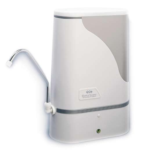
1 Use & Care
2 I. Specifications Model Maximum Working Pressure kg/cm 2 (125 PSI) Minimum Working Pressure kg/cm 2 (10 PSI) Maximum Water Temperature C (110 F) Minimum Water Temperature... 2 C (35 F) Recommended Tap Water Flow Rate LPM (0.7 GPM) Multi-media Filter Capacity...18,925 L (5,000 GAL) THIS WATER TREATMENT DEVICE IS INTENDED FOR, AND ONLY WARRANTED FOR, NON-COMMERCIAL USE ON MUNICIPALLY TREATED TAP WATER. This Use & Care outlines proper maintenance procedures which are essential for optimum filter performance. NOTE: The warranty is void if the specifications label on the unit is removed. MADE IN U.S.A. Rena Ware reserves the right to change the appearance of or make alterations to the model shown within. Therefore, your model may appear slightly different from the illustrations in this booklet. CAUTION: DO NOT USE WITH WATER THAT IS MICROBIOLOGICALLY UNSAFE OR WITH WATER OF UNKNOWN QUALITY WITHOUT ADEQUATE DISINFECTION BEFORE OR AFTER THE SYSTEM. SYSTEMS CERTIFIED FOR CYST REDUCTION MAY BE USED ON DISINFECTED WATER THAT MAY CONTAIN FILTERABLE CYSTS. AQUA 3 II 5000 Model No HP 5000 For cold water use only Max pressure 125 psi Max temperature 43 o C IMPORTANT: Follow manufacturers installation and maintenance instructions Plumbing Safety AS/NZS 3497 Appliance Cert Standards Australia T M CAUTION: DO NOT USE WITH WATER THAT IS MICROBIOLOGICALLY UNSAFE OR WITH WATER OF UNKNOWN QUALITY WITHOUT ADEQUATE DISINFECTION BEFORE OR AFTER THE SYSTEM. SYSTEMS CERTIFIED FOR CYST REDUCTION MAY BE USED ON DISINFECTED WATER THAT MAY CONTAIN FILTERABLE CYSTS. Rena Ware Dist. PTY LTD Castle Hill N.S.W AUSTRALIA
3 Table of Contents I. SPECIFICATIONS...page 2 II. PRECAUTIONS...page 4 III. INSTALLATION...page 5 15 IV. MAINTENANCE...page V. TROUBLESHOOTING...page VI. REPLACING COMPONENTS...page Dear Rena Ware customer; Please be sure to complete the information listed below for your records and future reference. AQUA 3 II WATER FILTRATION SYSTEM MODEL # 5000 SERIAL # CONTRACT # DATE INSTALLED LOCAL RENA WARE ADDRESS: 3
4 II. Precautions The AQUA 3 II Unit: 1. Read the instructions completely before operating your AQUA 3 II, and keep the Use and Care Manual in a convenient location for future reference. 2. Do not use the AQUA 3 II near open electrical current. 3. Do not run hot water (Above 48 O C/110 O F) through the AQUA 3 II because it may damage the unit. 4. Do not place the AQUA 3 II where it may easily fall and break. 5. Do not use the AQUA 3 II beyond product specifications. *See inside cover page for specifications. 6. Always replace the internal components before or at recommended capacities with genuine Rena Ware replacement components. 7. Always hold the AQUA 3 II firmly by the base when re-positioning or transporting the unit. 8. Avoid exposing your AQUA 3 II body-cover to salt, harsh chemicals, acidic foods, or direct sunlight. CAUTION: After two or more days of non-use, run water through the AQUA 3 II for five full minutes before resuming usage. This will help flush any standing water that may potentially contain bacteria, and allow your AQUA 3 II filter to provide water of optimum quality. Use of the appliance may increase the bacterial content unless supplemental treatment is provided. Internal Components the Pre-Filter Ceramic Candle: 1. Handle the pre-filter ceramic candle carefully never shake a pre-filter ceramic candle or knock it against other items, even while it is still in its original packaging. STORE IN A COOL PLACE. 2. Do not expose the pre-filter ceramic candle to prolonged direct or indirect sunlight. 3. Always hold the pre-filter ceramic candle firmly and gently in the middle of the component. DO NOT HOLD THE PRE- FILTER CERAMIC CANDLE BY EITHER END. Pre-filter ceramic candles will crack or break with improper handling. 4. When transporting the AQUA 3 II, remove the pre-filter ceramic candle and transport it separately, using the original packing material. The pre-filter ceramic candle may crack or break if transported within the AQUA 3 II unit. CAUTION: Water should be used promptly after filtration through the AQUA 3 II. We do not recommend storing filtered AQUA 3II water for more than 48 hours. Water filtered by the AQUA 3 II is free of bacteria inhibitors, such as chlorine, and therefore may be susceptible to bacteria growth after prolonged periods of time unless supplementary treatment is provided. 4
5 III. Installation Internal Components Filter Housings: Never use the housing wrench to tighten the filter housings use it only for loosening and removing the filter housings. Housings should always be hand-tightened only. III. Installation: Your AQUA 3 II is a high technology water filtration system. It consists of a ceramic pre-filter and main filter integrated by an advanced manifold system. Your AQUA 3 II will provide years of good service when properly cared for and maintained. ALWAYS PROPERLY CLEAN AND MAINTAIN YOUR AQUA 3 II FOR BEST RESULTS. READ ALL INSTRUCTIONS PRIOR TO INSTALLATION. Wash and dry your hands before beginning installation and make sure your work area is clean and dry. Remove all items from the box and check each item against the parts diagram (see parts list and diagram on pages 6 and 7). Note: You will find the small wrench affixed to the handle of the housing wrench. Hold the AQUA 3 II by the base when removing from the box, and place on the counter. Remove the pre-filter ceramic candle from its packing materials for the initial installation. WHEN HANDLING THE AQUA 3 II UNIT, ALWAYS HOLD IT FIRMLY AT THE BASE. DO NOT ATTEMPT TO LIFT THE AQUA 3 II BY THE BODY-COVER OR THE TUBING. To assist you in installing your AQUA 3 II, you may wish to have the following items available: pliers, flat blade screwdriver, petroleum jelly. NOTE: Different diverter valves are used on the Aqua 3 II 5000, depending on what country you live in. Some diverter valves have a pin that is pulled or slides to enable water to be filtered, and others have lever that needs to be turned. Installation is the same regardless of the type of valve you have. 5
6 III. Installation (continued) AQUA 3 II WATER FILTER PARTS: A adapters the optional attachments used to connect the diverter valve to the faucet B base contains flow meter and supports manifold C body-cover the shell which covers the two filter housings D clamp the small white device which holds the inlet tube onto the top barb of the diverter valve E diverter valve barbs the extensions on the diverter valve onto which the tubing is placed F diverter valve allows convenient at-faucet switching from tap to filtered water G flow-meter monitors the number of liters of water treated by the AQUA 3 II water filtration system H flow-meter viewing window allows you to view flow-meter I housing wrench used to loosen the filter housings if they become too tight to hand loosen; never use the housing wrench to tighten the filter housings. J manifold connects the pre-filter with the main filter K multi-media filter provides final multiple stage filtration of water L multi-media filter housing the white cylinder which covers the multi-media filter M O-rings creates seal between multi-media filter housing, prefilter housing and manifold 6 N pre-filter ceramic candle acts as a pre-filter, providing initial filtration of water before it passes on to multi-media filter O pre-filter housing the white cylinder which covers the prefilter ceramic candle P pressure release valve allows residual pressure to be released from the pre-filter housing Q scouring pad used to clean the pre-filter ceramic candle R small wrench used to disconnect the tubing from the tubing receptacles in the manifold S socket openings where the filters are inserted T tubing the double tubing which connects the diverter valve on the faucet with the AQUA 3 II water filtration system. The inlet tube extends from the top barb of the diverter valve to the tubing receptacle marked (+) and is marked with a black dashed line U tubing inserts the inserts at the end of each tube V tubing receptacles the openings in the manifold where the tubing is inserted, inlet (gray) and outlet (white) W release button press to release the base from the main unit X spout releases filtered water Y elbow attaches spout to tubing outlet receptacle Z single inlet tubing connects the single diverter valve to the inlet receptacle NOTE: Your Aqua 3 II 5000 will have either a spout or a double diverter valve assembly, depending on the model.


7 A C Q P O L R M X N K D Z I Y F D V S J E T U G B H W 7
.")
 Be careful not to push against the red pressure release valve. 3. THE PRE-FILTER CERAMIC CANDLE Remove a prefilter ceramic candle from its protective packaging.")

8 III. Installation (continued) AQUA 3 II INSTALLATION INSTRUCTIONS: Preparing the AQUA 3 II filter unit: 1. REMOVE THE AQUA 3 II BODY- COVER Lift the bodycover off and set it aside (see figure 1). 2. REMOVE THE PRE-FILTER HOUSING The pre-filter housing is closest to the tubing receptacles, and can be identified by the number 1 fig. 1 embossed onto the manifold (see figure 2). Unscrew the prefilter housing counter-clockwise, and set it aside. (If necessary, use the housing wrench supplied with your AQUA 3 II to loosen the pre-filter housing.) Be careful not to push against the red pressure release valve. 3. THE PRE-FILTER CERAMIC CANDLE Remove a prefilter ceramic candle from its protective packaging. USE CARE WHEN HANDLING THE PRE-FILTER CERAMIC CANDLE. Support the prefilter ceramic candle firmly in fig. 2 the center do not hold the pre-filter ceramic candle by the double O-ring end. Slightly moisten the O-rings with water before installing the pre-filter ceramic candle. 4. INSTALL THE PRE-FILTER CERAMIC CANDLE Insert the pre-filter ceramic candle into the socket revealed in Step 2 (see figure 3). Holding the prefilter ceramic candle firmly but GENTLY, with the double O-ring portion fig. 3 8

9 III. Installation (continued) pointed downward, apply a sliding pressure straight down then twist to slide the pre-filter ceramic candle into place. Make sure it is pushed all the way down. 5. REPLACE THE PRE-FILTER HOUSING Check to make sure that the O-ring is in place at the open end of the prefilter housing. (If the O-ring falls out, lay it back into the groove at the opening of the filter housing (see figure 4) and press into place with your fingers. A small amount of petroleum jelly can be applied to the O-ring to help hold it in place. Do not use vegetable, animal or motor oil.) Place the pre-filter housing over the prefilter ceramic candle and turn clockwise until hand-tight. DO NOT OVER-TIGHTEN. Never use the housing wrench to tighten the filter housings use it only for loosening and removing the filter housings. 6. CHECK THE MULTI-MEDIA FILTER The multi-media filter is on the side of the AQUA 3 II opposite the tubing receptacles, and can be identified by the number 2 embossed onto the manifold. Unscrew the multimedia filter housing counterclockwise, and set it aside. (If necessary, use the housing wrench supplied with your AQUA 3 II to loosen the housing (see figure 5).) The multi-media filter will already be in place. fig. 4 fig. 5 9

. Do not over-tighten the diverter valve. Over-tightening can cause the diverter valve to malfunction and/or break.")
10 III. Installation (continued) 7. REPLACE THE MULTI-MEDIA FILTER HOUSING Check to make sure the O-ring is in the groove at the open end of the multi-media filter housing. Place the multi-media filter housing over the multi-media filter and turn in a clockwise direction until HAND-TIGHT. DO NOT OVER-TIGHTEN. Preparing the faucet: 8. If your faucet has an aerator, remove aerator from the faucet (see figure 6). 9. The diverter valve is attached to the end of the tubing. Do not remove the tubing from the diverter valve. Thread the diverter valve onto the faucet, finger-tight only (see figure 7). Do not over-tighten the diverter valve. Over-tightening can cause the diverter valve to malfunction and/or break. If the diverter valve does not fit on the faucet, use an appropriate adapter. fig. 6 fig. 7 10
.")
 11.")
11 III. Installation (continued) (For spout models see Spout Installation, page 13) 10. Position the AQUA 3 II on the counter where desired. There are two tubes leading from the diverter valve; the inlet tubing is identified with a black-dashed line, and is connected to the top barb of the diverter valve with a clamp (see figure 8). The outlet tubing has no markings and and is connected to the bottom barb of the diverter valve. (You will notice that there are inserts positioned in the ends of each tube. Check to be sure that these inserts are in place.) 11. The manifold of the AQUA 3 II has two tubing receptacles the inlet opening is identified with a gray collar and a (+) under the hole to correspond with the black-dash lined inlet tube (see figure 9). Place the inlet tube, (connected to the top barb of the diverter valve), into the inlet opening gently push the tubing into the opening until it stops about 1.5 centimeters. Pull slightly on the tubing to ensure that the tube is secure. Then place the outlet tubing, connected to the bottom barb of the diverter valve, into the opening with the white collar, marked with a (0). Pull slightly on the tubing to make sure it is secure. 12. Turn the tap water on and engage the diverter valve (see figure 10). Note: Filtered water will always flow from the small nozzle, tap water will flow from the larger nozzle. fig. 8 fig. 9 fig


12 III. Installation (continued) 13. Push in the red pressure release valve located on the pre-filter housing (see figure 11) to allow air to escape. When only water starts to escape, release the valve. Wipe any water released through the pressure release valve off the pre-filter housing. Filtered water should now be flowing out of the small nozzle on the diverter valve or spout. Allow the water to flow through the AQUA 3 II for ten minutes to purge the system. Sudden bursts of water and air are normal the system is eliminating air pockets. 14. With the water running, check for leaks run your hands around all openings. Turn the unit upside down and rest it on the filter housings, and remove the base by pushing in on the base release buttons on the front and back of the manifold (see figure 12). Check for leaks around the flow-meter. If there are any leaking connections, turn the tap off and try tightening or re-connecting the problem section. 15. Snap the base back into place and turn the AQUA 3 II upright. 16. Replace the AQUA 3 II bodycover. Position the AQUA 3 II on the counter. Your new AQUA 3 II is now ready for use. fig. 11 fig
 into the end of the single tubing (G).(See photograph 1). 2.")
. 3.")
. When properly installed, the elbow will be almost flush to the white collar. 4.")
 straight up and down. The spout should rotate freely inside the white elbow. 6.")
13 III. Installation (continued) OPTIONAL SPOUT INSTALLATION: 1. Insert the tubing insert (D) into the end of the single tubing (G).(See photograph 1). 2. Push the tubing into the + inlet receptacle on the manifold, indicated by a + symbol and gray collar. (See photograph 2). 3. Push the white elbow (B) into the outlet indicated by the o symbol and white collar in the manifold. (See photograph 3). When properly installed, the elbow will be almost flush to the white collar. 4. Support the elbow from underneath and push the spout (A) firmly down into the while elbow (B) (See photograph 4). 5. Position the spout (A) straight up and down. The spout should rotate freely inside the white elbow. 6. Run the cold tap water and engage the diverter valve. Note: Filtered water only flows from the unit s spout; tap water only flows from the diverter valve. photograph 1 photograph 2 photograph 3 photograph 4 13
 from the manifold, then carefully remove the tubing inserts from both tubes.")

14 III. Installation (continued) INSTALLATION OPTIONS: TO ADJUST THE LENGTH OF THE TUBING (you will need a sharp knife) 1. To shorten the length of the tubing, remove the tubing (see figure 13) from the manifold, then carefully remove the tubing inserts from both tubes. With a knife, cut the tubing to the desired length (see figure 14). Then, replace the tubing inserts. 2. Insert the tubing into the manifold, making sure to connect the inlet tube in the gray receptacle of the manifold (see figure 15). fig. 13 WALL OR UNDER THE COUNTER INSTALLATION An optional mounting bracket may be available to allow your AQUA 3 II to be mounted to a wall or under the counter. Contact your local Rena Ware Customer Service Office. fig. 14 fig
. 3.")
.")

15 III. Installation (continued) UNIVERSAL ADAPTER INSTALLATION OPTIONS: TO USE THE UNIVERSAL ADAPTER TO ATTACH THE DIVERTER VALVE TO THE FAUCET: 1. Remove the top hose clamp from the universal adapter. 2. Slide this hose clamp over the spout on your faucet (see figure 16). 3. Push tubing end of adapter up onto the faucet spout. To ease sliding on the tubing, submerse the tubing in HOT water for 30 seconds. Use a towel when handling the adapter as it will be hot. 4. Slide the top hose clamp down over the tubing and faucet spout (see figure 17). Twist the hose clamps to the back. 5. Tighten hose clamp with a flat blade screwdriver do not over-tighten securing the adapter to the faucet spout. 6. Verify the hose clamp is secure around the tube and diverter valve adapter. 7. Thread the diverter valve onto the adapter (see figure 18). fig. 16 fig. 17 fig


16 IV. Maintenance Cleaning the exterior: Use a clean, damp cloth with mild dishwashing soap to clean the white portions of the body-cover. To remove fingerprints and water spots from the stainless steel portion of the body-cover, rub gently with a soft cloth. Do not let water spots dry on the stainless steel portion of the body-cover. You may use a high quality stainless steel polish to clean this portion of the body-cover, however we suggest testing it on a small section for scratching. Never use an abrasive cleanser on the stainless steel portion of the body-cover. Cleaning the pre-filter ceramic candle: Note: Sanitary precautions should always be taken when handling soiled components of your AQUA 3 II. We suggest using thin waterproof gloves. ALWAYS SUPPORT THE PRE-FILTER CERAMIC CANDLE BY HOLDING IT GENTLY BUT FIRMLY WITH ONE HAND. HOLD THE PRE-FILTER CERAMIC CANDLE IN THE CENTER NEVER HOLD IT BY ITS ENDS. The pre-filter ceramic candle will crack or break with improper handling. Clean the pre-filter ceramic candle whenever water-flow falls to an unacceptable rate. Before cleaning the pre-filter ceramic candle, it is necessary to drain out any existing water from the pre-filter housing. 1. Remove the body-cover from the AQUA 3 II, and set it aside. 2. Place the AQUA 3 II so that the tubing receptacles are over or in the sink. Gently push in on the inlet tubing, in the opening marked (+) with the gray collar. Slide the small wrench supplied with your AQUA 3 II around the inlet tubing, with the indented side of the wrench facing toward the unit, (see figure 19/19a) and while pushing in gently on the gray collar; pull out the tube with your other hand. Some water may drain from your AQUA 3 II. Do not remove the white, outlet tubing. NON-SPOUT MODELS SPOUT MODELS fig. 19 fig. 19a 16
, 1/4 to 1/2 turn counter-clockwise this will allow water in the pre-filter")
 4.")
17 IV. Maintenance (continued) 3. Turn the pre-filter housing, (the one closest to the tubing receptacles labeled with a number 1 embossed onto the manifold), 1/4 to 1/2 turn counter-clockwise this will allow water in the pre-filter to drain through the inlet opening (see figure 20). You can tip the AQUA 3 II slightly to further encourage drainage. Remember to hold the AQUA 3 II firmly by the base when repositioning or moving the unit. (If necessary, use the housing wrench to loosen the housing.) 4. When the water has stopped draining completely, remove the pre-filter housing by turning it counter-clockwise. Lift the pre-filter housing straight up off of the pre-filter ceramic candle, and set it aside. Be careful not to knock the pre-filter housing against the pre-filter ceramic candle the impact may cause the pre-filter ceramic candle to crack or break. 5. Using thin waterproof gloves, grip the pre-filter ceramic candle firmly in the middle and gently remove by twisting and lifting straight up (see figure 21). fig. 20 fig


18 IV. Maintenance (continued) 6. Clean the pre-filter ceramic candle by supporting the body of the pre-filter ceramic candle firmly in the middle with one hand, and gently scrub the prefilter ceramic candle with the scouring pad provided with your AQUA 3 II (see figure 22). Always brush away from the double O-ring end of the pre-filter ceramic candle. Clean the pre-filter ceramic candle using only water never use soap or detergents. Continue cleaning the pre-filter ceramic candle using slight pressure until it appears clean (white or off-white in color). Always support the pre-filter ceramic candle by holding it gently but firmly with one hand. Hold the pre-filter ceramic candle in the center never hold it by the fitted end. Prefilter ceramic candles will crack or break with improper handling. 7. Reinsert the pre-filter ceramic candle by applying a sliding pressure straight down then twist to slide the pre-filter ceramic candle into place (see figure 23). fig. 22 fig
 and press into place with your fingers.")
19 IV. Maintenance (continued) 8. Check to be sure that the O-ring is still in place at the open end of the pre-filter housing. (If the O-ring falls out, lay it back into the groove at the opening of the filter housing (see figure 24) and press into place with your fingers. A small amount of petroleum jelly can be applied to the O-ring to help hold it in place. Do not use vegetable, animal or motor oil.) Replace the pre-filter housing and secure by turning clockwise until hand-tight only. DO NOT OVER-TIGHTEN. Never use the housing wrench to tighten the pre-filter housing the housing wrench is only for loosening the filter housings. fig
. 10. Slowly turn the tap water on, switch the diverter valve to the filtered water position.")
20 IV. Maintenance (continued) 9. Reattach the tubing by reinserting the inlet tube into the opening with the gray collar and labeled with the (+). Push the tube in until it stops. Pull gently to ensure that the tubing is secure (see figure 25/25a). 10. Slowly turn the tap water on, switch the diverter valve to the filtered water position. Press in the red pressure release valve (see figure 26/26a) located on the pre-filter housing. Continue pressing while air and some water escapes from the valve. As soon as you notice only water escaping, release the valve. Wipe any water from the pre-filter housing with a soft cloth. 11. Filtered water should now be flowing freely through the small nozzle of the diverter valve or the spout. SPOUT MODELS DOUBLE DIVERTER MODELS (NON SPOUT) fig. 25 fig. 26 fig. 25a fig. 26a 20

21 IV. Maintenance (continued) To determine when to replace the pre-filter ceramic candle on your model, please consult the Component Replacement Chart page at the back of this manual. How to replace the pre-filter ceramic candle: 1. Follow steps 1 5 of Cleaning the pre-filter ceramic candle. 2. Using sanitary precautions, dispose of the soiled pre-filter ceramic candle (see figure 27). 3. Remove a new pre-filter ceramic candle from its protective packaging and follow the installation steps 7 11 of Cleaning the pre-filter ceramic candle. fig. 27 NOTE: Contact the Rena Ware Customer Service Office or your personal Rena Ware independent consultant to place an order for replacement pre-filter ceramic candles. 21

, in the opening with the white collar marked with a (0).")
. 3.")


22 IV. Maintenance (continued) When to replace the multi-media filter: The flow-meter will indicate when to replace the multi-media filter. Please refer to VI. Replacing Components at the back of this manual, for instructions that pertain to your model. 1. Remove the body-cover from the AQUA 3 II, and set it aside. 2. Place the AQUA 3 II so that the tubing receptacles are over the sink. Gently push in on the outlet tubing (or white elbow if using a spout), in the opening with the white collar marked with a (0). Slide the small wrench around the outlet tubing or spout elbow, with the indented side of the wrench facing the unit, and while pushing in gently on the white collar; pull out the tube or spout elbow (see figure 28/28a). 3. The multi-media filter is labeled with a number 2 embossed on the manifold (see figure 29), opposite the tubing receptacles. Turn the multi-media filter housing 1/4 to 1/2 turn counter-clockwise and allow the water to drain out through the outlet opening (see figure 30/30a). You can tip the AQUA 3 II slightly to further encourage drainage. Remember to hold the AQUA 3 II firmly by the base when repositioning or moving the unit. (If necessary, use the housing wrench to loosen the filter housing.) DOUBLE DIVERTER VALVE MODEL (NON SPOUT) fig. 28 DOUBLE DIVERTER VALVE MODEL (NON SPOUT) fig. 30 SPOUT MODEL fig. 28a 2 fig. 29 SPOUT MODEL fig. 30a 22

. 6. Install a new multi-media filter by placing it over the socket.")
.")
23 IV. Maintenance (continued) 4. Turn the multi-media filter housing counter-clockwise until you can lift it straight off of the multi-media filter, and set it aside. 5. Using proper sanitary precautions, pull straight up on the multi-media filter it should remove easily. Using sanitary precautions, dispose of the soiled multi-media filter (see figure 31). 6. Install a new multi-media filter by placing it over the socket. The multi-media filter should just rest loosely over the socket (see figure 32). 7. Check to make sure that the O-ring is still in the groove at the open end of the multi-media filter housing (see figure 33). Replace the multi-media filter housing by turning clockwise until hand-tight. DO NOT OVER-TIGHTEN. 8. Turn the unit upside down and rest it on the filter housings. Remove the base by pushing in on the base release buttons on the front and back of the manifold (see figure 34). fig. 31 fig. 32 fig. 33 fig
 (Apply the new label if supplied with your new multi-media filter by aligning the")
 (see figure 36/36a).")

24 IV. Maintenance (continued) 9. Rotate the flow-meter knob clockwise until the notch on the label aligns with the white indicator on the flow-meter body(see figure 35). You should have marked the 1/2 box when resetting your flow meter at the half life (see page 27 Replacing Components) (Apply the new label if supplied with your new multi-media filter by aligning the notch on the label with the indicator on the flow-meter body.) Replace the base. 10. Turn the filter upright, and reinsert the outlet tubing or spout into the AQUA 3 II tubing receptacle with a white collar and marked with a (0) (see figure 36/36a). Engage the diverter valve, and turn the tap water on. Check the whole unit for water leaks. 11. If no leaks are found, replace the body-cover and flush for two minutes. Note: If you find a leak that cannot be corrected by re-attaching all of the connections, contact your local Rena Ware Customer Service Office. fig. 36 fig. 35 DOUBLE DIVERTER VALVE MODEL (NON SPOUT) SPOUT MODEL fig. 36a Note: Over time, a diverter valve may lose its lubrication and become more difficult to operate. To improve performance, place a small drop of petroleum jelly (e.g. Vaseline), or silicone grease at the points shown. VALVE STEM Apply lubricant here, and on opposite side 24
25 V. Troubleshooting 1. Water does not flow through the filter Is the diverter valve in the proper position for filtered water? Adjust the diverter valve to the proper position. Is the tubing folded or pinched? Make sure the tubing is smooth and straight. Check multi-media filter if your multi-media filter has an arrow, it should be pointing down. Is the viewing window of the flow-meter registering as red? If so, refer to Section VI. Replacing Components. Inspect the pre-filter ceramic candle is it clean? The pre-filter ceramic candle may become clogged, preventing water flow. Clean the pre-filter ceramic candle thoroughly according to the directions in Section IV. Maintenance. 2. Water leaks out of filter housings Check both filter housings and hand-tighten until water stops leaking. If water continues to leak out of a filter housing, drain the AQUA 3 II unit completely and remove both filter housings. (Refer to Section IV. Maintenance, Cleaning the pre-filter ceramic candle, steps #1 through #7, pages and Replacing the multi-media filter, steps #1 through #11, pages ) Check to make sure the O-ring is properly seated in each filter housing. (See Section III. Installation, step #5, page 9.) A small amount of petroleum jelly can be applied to the O-ring to help hold it in place. Do not use vegetable, animal or motor oil. 3. Water leaks from tubing receptacles in manifold Push tube(s) further into receptacles. Remove the tubing and verify that the inserts are still in place (see Section III. Installation, step #10, page 11). 4. Water leaks from tubing Check tubing for cuts or nicks. If a portion of the tubing is leaking, it must be replaced with a new length of AQUA 3 II tubing. Contact the Rena Ware Customer Service Office for replacement parts. If water is leaking at the diverter valve, push the tubing firmly over the diverter valve barbs. Make sure the inlet tube (the one with the black dashed line on the double diverter models) is attached to the top barb of the diverter valve, and the clamp is tight tighten if necessary. 25

26 V. Troubleshooting (continued) 5. One of the filters won t drain Make sure the appropriate tube or spout is removed completely from the tubing receptacle. Turn the filter housing counter-clockwise 1/4 turn. If the filter still won t drain, continue turning the filter housing counter-clockwise in small increments until water flows out of unit at the tubing receptacles. (Be careful not to turn the filter-housing too far, water may be released from housing and spill out over the base.) 6. Water continues to flow out of filtered water diverter valve nozzle after water is turned off Some water may continue to flow after shut off due to the build-up of pressure within the unit. This is normal. If water flows for longer than one minute, remove the body-cover and press the red pressure release valve located on the pre-filter housing. Continue pressing the valve until water escapes instead of air. As soon as only water escapes, release the valve. Wipe any water from the pre-filter housing with a soft cloth. Replace the body-cover. You may also invert the entire filter in the sink (positioning the spout so the flow does not spray out of the sink) and run for 3-5 minutes. This will help purge air trapped in the water system allowing better water flow. 7. Flow-meter viewing window registers yellow... Refer to Section VI. Replacing Components at the back of this manual. VI. Replacing Components Your AQUA 3 II is a modular system that should last for years with proper maintenance and regular replacement of components using genuine Rena Ware parts. Please refer to the Component Replacement Chart on the back of this manual for information about when to replace components. Half-life of the multi-media filter Your multi-media filter will reach half-life after filtering 9,462 liters (2,500 gallons) of water. When you first put your unit in service, the flow meter viewing window will register as green. As you near the half-life point, the flow-meter viewing window will register as yellow, and then red when the half-life point has been reached. At this point, the flow meter will shut the system off, indicating the need to service the unit. Remove the filter base and expose the flow meter see fig, 34 page 23). Using a pen, mark the box on the flow meter label next to 1/2. This will be your indication that the half-life of the multi-media filter has been reached. Then rotate the flow-meter clockwise until the notch on the label aligns with the indicator on the flow-meter body (see figure 37). fig
27 Replace the base and return the unit to operation. There is no need to replace the multi-media filter at this time; it is capable of filtering another 9,462 liters 2,500 gallons) of water. The flow meter viewing window should register green again. When to replace the multi-media filter When the flow-meter viewing window registers yellow - it is almost time to replace the multi-media filter. You should order a replacement multi-media filter at this time. When the multi-media filter reaches its full capacity, the flow-meter viewing window will register as red and water flow will be shut off. You will need to replace the multi-media filter at this time. (For instructions on how to replace the multi-media filter, please refer to Section IV. Maintenance, How to replace the multi-media filter.) The interruption in water flow is a built-in safety precaution so that you will know your filter is no longer capable of filtering your water properly and needs to be replaced. Replacement components are sold separately - please contact your Rena Ware Customer Service Office. ALWAYS USE GENUINE RENA WARE REPLACEMENT PARTS, OBTAINED THROUGH THE LOCAL AUTHORIZED RENA WARE CUSTOMER SERVICE OFFICE. Rena Ware components contain advanced internal media which may not be present in other filters. Component Replacement Chart - Model 5000 COMPONENT REPLACE Pre-filter ceramic candle...when cleaning the pre-filter ceramic...candle has failed to restore the desired...flow from the diverter valve. Multi-media filter...every 18,925 liters (or 5,000 gals.) Reset Flow Meter at 9,462 liters ( 2,500 gallons) half-life. Diverter valve & tubing...every months. O-rings...O-rings may become worn after...repeated opening/closing of the filter...housings. Replace if the O-rings are...cracked, warped or broken. 27
28 Warranty The Rena Ware Warranty Rena Ware warrants its AQUA 3 water filtration systems to be free from defects in materials and workmanship for one year from the date of purchase. This Product is for home use on municipally treated water only. This Warranty does not cover damage resulting from use of the Product on water having high chemical interference, suspended materials or visual solids. This Warranty does not cover normal wear and tear of valving connections, rubber and plastic parts, or ceramics. This Warranty does not cover defects resulting from misuse, abuse, negligence, accident, use of the Product in a manner other than as described in the instructions and on the specifications label, repair or alteration outside a Rena Ware facility, or lack of maintenance. Use of replacement parts other than genuine Rena Ware replacement parts or removal of the specifications label will void this Warranty. This Warranty does not cover incidental or consequential damages resulting from the use of this Product. Remedy in the Event of Warranty Claim At its option, Rena Ware will repair or replace a Product, or any part thereof, which is determined to be defective within one year from the date of purchase. If a replacement is made, the Product for which the replacement is made becomes the property of Rena Ware. This remedy shall be the exclusive remedy available. To Obtain Warranty Service To obtain warranty service, send a detailed written description of the claimed defect to the Rena Ware Service Center. You may be required to return the Product, at your expense, to the nearest Rena Ware Service Center in order to obtain warranty service. You may also be required to provide proof of purchase. If, after inspection, Rena Ware determines that a covered defect exists, Rena Ware will bear the cost of return delivery. Other Warranty Limitations This Warranty is in lieu of all other express warranties. Any implied warranty shall be equal in duration to the above express Warranty. Some jurisdictions do not allow the exclusion or limitation of incidental or consequential damages, or do not allow limitations on how long an implied warranty lasts, so the above limitations or exclusions may not apply to you. This Warranty gives you specific legal rights. You may also have other rights which vary from jurisdiction to jurisdiction. This Warranty applies to AQUA 3 water filtration systems only. Separate warranties apply to cookware and other Rena Ware products. AQ 347 MODEL PRINTED IN U.S.A Copyright 2002 R.W.I.
Full Flow Drinking Water System Model: 3MFF100
 Installation and Operating Instructions For Full Flow Drinking Water System Model: 3MFF100 System tested and Certified by NSF International against NSF/ANSI Standard 42 and 53 for the reduction of the
Specialty Pond Sprayer
 Specialty Pond Sprayer 2.75 Gallon Capacity Sprayer Installation & Maintenance Manual (Item # 580121) 1 Year Warranty Specialty Pond Sprayer 2.75 Gallon Capacity Sprayer Thank you for purchasing this compression
INSTALLATION INSTRUCTION & OWNER S MANUAL
 CS-2500 & CS-2500P Water Filtration System INSTALLATION INSTRUCTION & OWNER S MANUAL Ver 1.2 All Rights Reserved APEC Water Systems Please keep this Owner s Manual for future reference. It contains useful
Installation, Operation and Maintenance Manual
 IOM-HS-QTColdBevMax Installation, Operation and Maintenance Manual QT TM Cold Bev Max TM Models: QTCLDBMX-1S-.5M, QTCLDBMX-2S-.5M, QTCLDBMX-3S-.5M, QTCLDBMX-4S-.5M, QTCLDBMX-5S-.5M Tested and Certified
Dual Flow Manifold Systems Instruction Manual
 3M TM Water Filtration Products Dual Flow Manifold Systems Instruction Manual For DF1XX and DF2XX High Flow Series manifolds and water filtration systems Installer: Please leave this manual with owner/operator.
2-DOOR LAUNDRY CABINET KIT
 2-DOOR LAUNDRY CABINET KIT OWNER S MANUAL QL055 # 6725161 Table of Contents Table of Contents...2 Safety Information...2 Warranty...3 Warranty Claim Procedure...3 Pre-Installation...4 Tools/Materials Required...4
Dual/Triple Manifold Water Filtration Systems Instruction Manual
 3M TM Water Filtration Products Dual/Triple Manifold Water Filtration Systems Instruction Manual High Flow Series Water Filtration Systems Installer: Please leave this manual with owner/operator. 3M Water
SAVE FOR CONSUMER INSTALLATION / OWNER'S MANUAL. Single Handle Kitchen Faucet Model # LK2500. Important! You choose the flow rate!
 INSTALLATION / OWNER'S MANUAL Single Handle Kitchen Faucet Model # LK500 Important! You choose the flow rate! This faucet ships with an eco-friendly.5gpm flow regulator installed. If you desire higher
Installation. Tools. Single Handle Kitchen Faucet With Optional Spray. Maintenance. Safety Tips. Important Points. Need Help? For Model:
 Installation Tools - Basin Wrench - Adjustable Wrenches - Pipe Wrench - Screwdriver - Thread Seal Tape - Supply Lines - Protective Goggles - Silicone Sealant - Pliers - Soft Cloth For Model: 673-6809 Single
Owner s Manual WARNING
 Filter Housing Models: AWP20C-V, AWP30C-V, AWP32B-V. Overview: Owner s Manual VIQUA offers a variety of housing sizes and styles in durable, molded polymer that defies rust and corrosion, and ensures a
EBF-750 Deck-Mounted Battery Powered Sensor Operated Gooseneck Faucets
 INSTALLATION INSTRUCTIONS BATTERY POWERED SENSOR OPERATED HAND WASHING FAUCETS EBF-750 I.I. Code No. 0816324 EBF-750 Deck-Mounted Battery Powered Sensor Operated Gooseneck Faucets Includes Instructions
NSF MODELS: CTP200, CTP100. This System does not require the services of a plumber. Read and Save these Instructions. Important
 INDEPENDENTLY Installation, Use & Care Guide Countertop Filter Systems MODELS: CTP200, CTP100 This System does not require the services of a plumber. Important Read and Save these Instructions CTP200 shown
INSTALLATION INSTRUCTIONS TOP MOUNT SINKS
 These instructions are for installing top mount stainless steel sinks. (CH365 and CH366 NOT included) Please read all instructions carefully before starting the installation. TABLE OF CONTENTS Preparation
AQUA2000 From O3PURE
 AQUA2000 From O3PURE OWNER S MANUAL INCLUDES: RESTRICTIONS INSTALLATION OPERATION MAINTENANNCE CHANGING THE FILTER CHANGING THE UV LAMP SPECIFICATIONS WARRANTY ADVANCED WATER TREATMENT SYSTEMS CAUTION:
Installation, Operation and Maintenance Manual
 IOM-HS-QTCubeMax Installation, Operation and Maintenance Manual QT TM Cube Max TM Models: QTCBMX-1S-1M, QTCBMX-2S-1M, QTCBMX-3S-1M, QTCBMX-4S-1M, QTCBMX-1L-1M, QTCBMX-2L-1M, QTCBMX-3L-1M, QTCBMX-4L-1M,
MULTI-STAGE FILTRATION SYSTEM INSTALLATION INSTRUCTIONS
 MULTI-STAGE FILTRATION SYSTEM INSTALLATION INSTRUCTIONS Model #: 30101 Model #: 30102 Replacement Cartridge INSTALLATION GUIDE ABOUT THIS SYSTEM Congratulations on your purchase of the 30101 Multi-Stage
Serial Number Purchase Date
 ITEM #02708 KITCHEN FAUCET MODEL #6720-20 Français / Español p. 8 ATTACH YOUR RECEIPT HERE Serial Number Purchase Date Questions, problems, missing parts? Before returning to your retailer, call our customer
Installation Kitchen Faucet Filtration System Instructions GXK285JBL
 Installation Kitchen Faucet Filtration System Instructions GXK285JBL BEFORE YOU BEGIN Read these instructions completely and carefully. IMPORTANT Save these instructions for local inspector s use. IMPORTANT
Scale Feeder Manifold Water Filtration System Instruction Manual
 3M TM Water Filtration Products Scale Feeder Manifold Water Filtration System Instruction Manual For SF1XX High Flow Series Water Filtration Systems Installer: Please leave this manual with owner/operator.
PACIFICA Shower Cabin Installation Instructions
 PACIFICA Shower Cabin Installation Instructions IMPORTANT Please read carefully the following instructions before installing your shower cabin. If you have any questions on this shower cabin installation
Instructions. Certifications. Two Handle Kitchen Faucet. Tools Required. Maintenance. Safety Tips. Important Points. Things You May Need.
 116874 Chrome less 116864 PVD brushed nickel with 0-K8-CYCH-AD-Z Chrome with 0-K8-CYBN-AD-Z PVD brushed nickel with 0-K8-CNCH-AD-Z Chrome less 0-K8-CNBN-AD-Z PVD brushed nickel less *Image may vary slightly
Instructions. Certifications Chrome less spray Chrome with spray 10-K82-WNCH-AD-Z Chrome less spray 10-K82-WYCH-AD-Z Chrome with spray
 Instructions *Image may vary slightly from actual product Tools Required Adjustable Wrench Groove Joint Pliers Pipe Wrench Phillips Screwdriver Pipe Tape or pipe thread compound Safety Tips If you solder
INSTALLATION INSTRUCTIONS CARE AND MAINTENANCE
 1 2 3 4 5 6 7 8 9 10 11 12 13 14 15 16 17 18 19 20 21 22 23 24 INSTALLATION INSTRUCTIONS CARE AND MAINTENANCE CURVED APRON FRONT STAINLESS STEEL SINK Flush Mount or Under Mount Sink Thank you for selecting
INSTALLATION INSTRUCTIONS TOP MOUNT SINK CH366
 27688 Industrial Blvd, Hayward, CA 94545 Tel: (877) 329 6872 Fax: (510) 723 0099 dp@dawnusa.net These instructions are for installing top mount sink CH366. Please read all instructions carefully before
Single Lever Pull-Out Kitchen Faucet
 INSTALLATION GUIDE Single Lever Pull-Out Kitchen Faucet KPF-1621 www.kraususa.com I Toll Free: 1.800.775.0703 I 2017 Kraus USA Inc. I REV. October 25, 2017 Congratulations on the purchase of your new Kraus
PURE WATER. Installation, Operation and Maintenance Manual. 3-Stage Under Counter Filtration with UV Model PWSYS-UV-3STG. Important.
 Installation, Operation and Maintenance Manual 3-Stage Under Counter Filtration with UV Model PWSYS-UV-3STG IOM-WQ-PWSYS-UV-3STG PURE WATER Important Please read the entire manual before proceeding with
AQUA2000 ADVANCED WATER TREATMENT SYSTEMS OWNER S MANUAL INCLUDES: Restrictions. Installation. Operation. Maintenance. Changing the Filter
 The world leader in products for a healthy and comfortable environment - bringing the Garden of Eden into your home. AQUA2000 OWNER S MANUAL INCLUDES: Restrictions Installation Operation Maintenance Changing
Fabric Replacement Top and Doors with Tinted Side and Rear Curtains Installation Instructions
 Fabric Replacement Top and Doors with Tinted Side and Rear Curtains Installation Instructions For: Wrangler/TJ 1997-2002 Part Number: 51124 www.bestop.com DO NOT INSTALL THIS PRODUCT ON ANY VEHICLE OTHER
( Versions Available)
") STYLE 494 ELECTRIC LADDER PIPE INSTALLATION, OPERATING AND MAINTENANCE INSTRUCTIONS ( Versions Available) The following is intended to provide the basic instructions for installation, operating and maintenance
STYLE 494 ELECTRIC LADDER PIPE INSTALLATION, OPERATING AND MAINTENANCE INSTRUCTIONS ( Versions Available) The following is intended to provide the basic instructions for installation, operating and maintenance
18 KG MOBILE SODA BLASTING UNIT
 OWNER S MANUAL PRODUCT CODE: 3043 18 KG MOBILE SODA BLASTING UNIT Working Air Hose Tank Volume Overall Dimensions Pressure Consumption Length 18KG 35 90psi 6-12CFM 2400mm 460 x 305 x 660 Made in China
Installation Instructions
 Installation Instructions To ensure that your installation proceeds smoothly--please read these instructions carefully before you begin. P r o d u c t s Luxury Faucets and Accessories Savina Product Numbers
IV STANDS. Assembly, Usage and Maintenance INSTRUCTION MANUAL
 INSTRUCTION MANUAL IV STANDS Assembly, Usage and Maintenance Read and understand all of the instructions and safety information in this manual before operating this product. MAN-045 REV A 2018 MAC Medical,
Shower System. Dual Head INSTRUCTION GUIDE
 INSTRUCTION GUIDE Step-By-Step Illustrated Installation Instructions Jet Cleaning Instructions Proper Finish Care Limited Warranty Read these instructions carefully before installing your new shower system
WARNING Carefully Read These Instructions Before Use
 DO NOT RETURN THIS SPRAYER TO STORE Call: 1-800-950-4458 Backpack Sprayer Use and Care Manual Manufactured for Northern Tool + Equipment Co., Inc. WARNING Carefully Read These Instructions Before Use Model
Owner s Manual FS-10/FreshSpa
 Owner s Manual FS-10/FreshSpa Table of Contents Product Features................ Page 2 Parts List....................... Page 3 Configuration................... Page 4 Installation.....................
Installation Instructions / Warranty. Starck 10444XX XX1
 Installation Instructions / Warranty Starck 10444XX1 10454XX1 90564101 06/2005 Starck 4-Hole Roman Tub Trim 10444XX1 10454XX1 10444XX1 10454XX1 Installation Considerations This trim kit must be used with
INSTALLATION INSTRUCTIONS UNDERMOUNT SINKS
 Kitchen & Bath Products, Inc. 27688 Industrial Blvd, Hayward, CA 94545 1-877-329-6872 dp@dawnusa.net These instructions are for installing undermount sinks. Please read all instructions carefully before
Installation Instructions
 Installation Instructions To ensure that your installation proceeds smoothly--please read these instructions carefully before you begin. P r o d u c t s Luxury Faucets and Accessories Savina Product Numbers
Agxcel GX12i Chemical Injection System
 Agxcel GX12i Chemical Injection System Table of Contents System Contents... 3 Specifications... 4 Safety Precautions and Tips... 5 Operations... 6 Installation... 7 Maintenance... 8-9 Troubleshooting...
Dual Port Manifold Water Filtration Systems Instruction Manual
 M TM Water Filtration Products Dual Port Manifold Water Filtration Systems Instruction Manual For DP1XX, DP2XX and DPXX High Flow Series Water Filtration Systems Installer: Please leave this manual with
Heavy Duty Engine Cranes
 Heavy Duty Engine Cranes Operating Instructions & Parts Manual Model Number Atd-7484 Atd-7485 (Foldable Legs) Capacity 2 Ton 2 Ton Model Atd-7484 Model Atd-7485 Atd Tools Inc. 160 Enterprise Drive, Wentzville,
Installation Instructions Model: AB Single-lever Pull-down Spray Faucet
 Kitchen & Bath Products, Inc. www.dawnusa.net Installation Instructions Model: Single-lever Pull-down Spray Faucet TABLE OF CONTENTS Preparation 2 Parts & Tools Needed 2 Installation 3-5 Care and Cleaning
The ionpia H 2 Owner s Manual
 Hydrogen Enhanced Living The ionpia H 2 Owner s Manual Only from AlkaViva Warning: Incorrect installation and/or operation could void your valuable warranty. Please protect your investment! READ THIS MANUAL
Spotlight 1,000,000 Power Series Cordless Rechargeable
 VEC156CFL_Manual_012405 1/24/05 4:29 PM Page iv VEC156 Spotlight 1,000,000 Power Series Cordless Rechargeable OWNER S MANUAL & WARRANTY INFORMATION 53SB E231887 IMPORTANT SAFETY INFORMATION, SAVE THESE
Installation Instructions / Warranty
 Installation Instructions / Warranty Axor Citterio 39133XX1 Axor Citterio 39135XX1 Axor Citterio 39233XX1 Axor Citterio 39235XX1 Axor Citterio Widespread Lavatory Faucet Axor Citterio Widespread Bidet
2 Speed Hydraulic Hand Pump
 Porto-Power Blackhawk Automotive is a licensed trademark 2 Speed Hydraulic Hand Pump Operating Instructions & Parts Manual B65122 B65421 SFA Companies 10939 N. Pomona Ave. Kansas City, MO 64153 816-891-6390
Spin Klin 3"-4" Apollo Angle
 Spin Klin 3"-4" Apollo Angle w w w. a r k a l - f i l t e r s. c o m 3"-4" Spin Klin Angle Apollo Battery Service & Maintenance Manual Table of Contents Subject Page No. 1. Introduction... 3 2. Safety
Installation Instructions / Warranty
 Installation Instructions / Warranty Axor Citterio 39144XX1 Axor Citterio 39148XX1 Axor Citterio Wall Mount Lav Mixer with Cross Handles 39144XX1 Axor Citterio Wall Mount Lav Mixer with Lever Handles 39148XX1
ROMAN TUB 3 VALVE LONG STEM AND TRIM INSTALLATION INSTRUCTIONS Valve Body No Trim Kit for Model No s: 1047, 1707, 1727
 ROMAN TUB 3 VALVE LONG STEM AND TRIM INSTALLATION INSTRUCTIONS Valve Body No. 1-523 Trim Kit for Model No s: 1047, 1707, 1727 Congratulations on the purchase of this Newport Brass product, an excellent
ETF-600 Sensor Operated Lavatory Faucet
 INSTALLATION INSTRUCTIONS OPTIMA SYSTEMS SENSOR OPERATED LAVATORY FAUCET ETF-600 I.I. Code No. 0816318 ETF-600 Sensor Operated Lavatory Faucet Includes Instructions for Installation of Optional Back Checks
6-12 WIDESPREAD 6-12 W. Cleopatra Series INSTRUCTION GUIDE SAVE THIS INSTRUCTION GUIDE
 INSTRUCTION GUIDE STEP-BY-STEP ILLUSTRATED INSTALLATION INSTRUCTIONS TROUBLE SHOOTING & REPAIR TIPS 20 YEAR LIMITED WARRANTY PROPER FINISH CARE Read these instructions carefully before installing your
Intended Use: Explanation of Signal Word Consequences
 SAFETY INFORMATION & INSTRUCTION MANUAL Please read, understand, and follow all safety information contained in these instructions prior to the use of this device. Retain these instructions for future
Battery Powered Sensor Operated Lavatory Faucets. Plug-in Transformer Powered Sensor Operated Lavatory Faucets PARTS LIST
 1A 1B 8 EAF-100/150 I.I. Rev. 0a (11/02) Code No. 0816542 INSTALLATION INSTRUCTIONS ELECTRONIC, SENSOR OPERATED LAVATORY FAUCETS EAF-150 Series Battery Powered Sensor Operated Lavatory Faucets 2 3 7 10
Installation Instructions / Warranty
 Installation Instructions / Warranty Citterio 39136XX1 39156XX1 Citterio 39236XX1 Axor Citterio Widespread Lav Mixer 39136XX1 Axor Citterio Bidet Mixer 39236XX1 39136XX1 User instructions Turn the right
32 lbs / 38 lbs TROLLING MOTOR
 32 lbs / 38 lbs TROLLING MOTOR MODEL: 90000 / 90001 OPERATOR'S MANUAL TOLL-FREE HELPLINE: 1 866 523-5218 IMPORTANT: READ THIS MANUAL CAREFULLY BEFORE OPERATNG YOUR NEW TM DURAMAXX TROLLING MOTOR. RETAIN
PowerFlo 20 Parts List/Assembly Instructions/Users Guide ***PLEASE READ ALL INSTRUCTIONS CAREFULLY AND THOROUGHLY***
 PowerFlo 20 Parts List/Assembly Instructions/Users Guide ***PLEASE READ ALL INSTRUCTIONS CAREFULLY AND THOROUGHLY*** Owners Manual (Please check to make sure to locate all parts before assembly.) 11/12/2008
OWNER S MANUAL PRODUCT CODE: 2006T
 Jul-18 Product Code: 2006T OWNER S MANUAL PRODUCT CODE: 2006T HYDRAULIC PIPE BENDER 12,000KG Model Capacity Bending Die No of Attachments 12,000kg 1/2", 3/4", 1", 1-1/4", 1-1/2", 2" 6 Made in China to
Installation Instructions To ensure that your installation proceeds smoothly--please read these instructions carefully before you begin.
 Single Lever Vessel Faucet Installation Instructions To ensure that your installation proceeds smoothly--please read these instructions carefully before you begin. P r o d u c t s Luxury Faucets and Accessories
5 5 8 " Description Part # Description Part # O-ring. Tee Connector. Widespread Handle * 1.5 GPM Flow Restrictor PM-080
 VOGUE COLLECTION WIDESPREAD LAVATORY SET WITH VO HANDLES MODEL: 6520VO10 6520VO PARTS BREAKDOWN 10 18 2 19 1 5 5 11 16 4 17 12 9 8 13 6 13 14 3 14 7 15 7 15 5 5 8 " Description Part # Description Part
SUPERPLUS WATER FILTRATION SYSTEM
 SUPERPLUS WATER FILTRATION SYSTEM For Model #: SP20-1 INSTRUCTIONS/ASSEMBLY USE AND CARE MANUAL (Important: Read this manual thoroughly before install) TABLE OF CONTENTS 2 3 4 6 8 9 10 11 12 General Notes
OWNER S MANUAL EVOLUTION 3500, 4500, 5500, & 8500 SERIES PUMPS
 OWNER S MANUAL EVOLUTION 3500, 4500, 5500, & 8500 SERIES PUMPS IMPORTANT SAFETY INSTRUCTIONS When installing and using this electrical equipment, basic safety precautions should always be followed, including
GRSM17 Pneumatic Center Punch Tool Owner s Manual and Operating Instructions
 Owner s Manual and Operating Instructions Table of Contents Page Information 2 Safety Guidelines and Warranty 3 Overview and Installation 4 Air System Requirements 5 Setting Controls 6 Installing Clamps
Pressurized Bead Filters
 Pressurized Bead Filters Installation Instructions Table of Contents Safety Information Installation Assembly Start Up Maintenance Troubleshooting Warranty Safety Information: 1. Installation should be
INSTALLATION GUIDE KPF Single Lever Kitchen Faucet With Pull-Out Sprayer
 INSTALLATION GUIDE KPF-21 Single Lever Kitchen Faucet With Pull-Out Sprayer www.kraususa.com I Toll Free: 1.800.775.0703 I 2017 Kraus USA Inc. I REV. August 7, 2017 Congratulations on the purchase of your
4" Spin Klin Twin Apollo Battery. Service & Maintenance Manual
 4" Spin Klin Twin Apollo Battery Service & Maintenance Manual Table of Contents Subject Page No. 1. Introduction... 3 2. Safety Instructions... 3 3. Description and Operation... 4 4. Technical Data...
2-DOOR LAUNDRY CABINET KIT
 2-DOOR LAUNDRY CABINET KIT OWNER S MANUAL QL054 # 6725159 Table of Contents Table of Contents....2 Safety Information....2 Warranty....3 Warranty Claim Procedure....3 Pre-Installation....4 Tools/Materials
Spin Klin 4" Apollo Twin
 Spin Klin 4" Apollo Twin w w w. a r k a l - f i l t e r s. c o m 4" Spin Klin Twin Apollo Battery Service & Maintenance Manual Table of Contents Subject Page No. 1. Introduction... 3 2. Safety Instructions...
Owner s Manual & Safety Instructions
 Owner s Manual & Safety Instructions Save Save This This Manual Keep Keep this this manual manual for for the the safety safety warnings warnings and and precautions, assembly, assembly, operating, inspection,
Use & Care Manual D R I N K I N G W A T E R S Y S T E M S. IMPORTANT: Read and Save these Instructions
 MODELS F P5000/F P4500/F P4000 D R I N K I N G W A T E R S Y S T E M S Use & Care Manual System Tested and Certified by NSF International against NSF/ANSI Standard 42 for the reduction of Chlorine Taste
INSTALLATION INSTRUCTIONS STUDIO S
 INSTALLATION INSTRUCTIONS STUDIO S 70.0 MONOBLOCK LAVATORY FAUCET WITH SPEED CONNECT Thank you for selecting American Standard... the benchmark of fine quality for over 00 years. To ensure that your installation
4" 4" 4 1/4" 11" TOP VIE 3 1/8" Ø1/2" 2" 10 3/8" SIDE VIE VG05002 THE MEASUREMENTS IN INCHES ARE ROUNDED TO THE NEAREST 1/8"
 FAUCET SPECIFICATIONS all Mount Bathroom Faucet Model VG05002 MODEL VG05002 FEATURES Solid brass construction Single hole construction Ceramic disk cartridge Single lever faucet all mount installation
Backpack Sprayer. Use and Care Manual
 Backpack Sprayer Use and Care Manual BACKPACK SPRAYER CAUTION: Read and follow all instructions Do Not Return This Backpack To The Store For Help, Information or Parts, Call : 1-800-311-9903 The Fountainhead
Artec Pro Single Handle Commercial Kitchen Faucet
 INSTALLATION GUIDE Artec Pro Single Handle Commercial Kitchen Faucet KPF-603 www.kraususa.com I Toll Free:.800.775.0703 I 208 Kraus USA Inc. I REV. Aug 2, 208 Congratulations on the purchase of your new
OPERATIONS MANUAL LEVER CHAIN HOIST
 OPERATIONS MANUAL LEVER CHAIN HOIST IMPORTANT SAFETY INFORMATION Please read, understand and follow all safety information contained in these instructions prior to the use of this hoist. Retain these instructions
Fission. Nano-Protein Skimmer. Instructions for Model#8100
 Fission Nano-Protein Skimmer Instructions for Model#8100 Warning and Safety Instructions... Page 2 Skimmer Assembly... Page 3 Skimmer Installation... Page 5 Skimmer Maintenance... Page 7 Warranty... Page
INSTALLATION INSTRUCTIONS
 INSTALLATION INSTRUCTIONS Thank you for purchasing VANISH Roll-Up Cover. Agri-Cover, Inc. proudly manufactured this cover using superior quality materials and workmanship. With proper care, your cover
Aplos Single Lever Basin Faucet
 INSTALLATION GUIDE Aplos Single Lever Basin Faucet KEF-15301 www.kraususa.com I Toll Free: 1.800.775.0703 I 2017 Kraus USA Inc. I REV. October 25, 2017 Congratulations on the purchase of your new Kraus
Twin-Beam Spotlight 3,000,000 Power Series Corded Cordless Rechargeable
 VEC158CFL_Manual_012405 1/24/05 4:37 PM Page iv VEC158 Twin-Beam Spotlight 3,000,000 Power Series Corded Cordless Rechargeable OWNER S MANUAL & WARRANTY INFORMATION IMPORTANT SAFETY INFORMATION, SAVE THESE
Heavy Duty Four Wheeled Walker
 Heavy Duty Four Wheeled Walker Weight Capacity: 500 lbs. ITEM # W1802 Made in China 2011 ESSENTIAL MEDICAL SUPPLY, INC. Manufactured for Orlando, FL 32822 -- SAVE THESE INSTRUCTIONS -- Do not attempt to
Read this entire manual before operation begins.
 Read this entire manual before operation begins. Record below the following information which is located on the serial number data plate. Serial No. Model No. Date of Installation Contents Specifications.............
Water Broom. Instruction manual ESPAÑOL: PÁGINA 7 FRANÇAIS : PAGE 13 MODEL PCA270
 ESPAÑOL: PÁGINA 7 FRANÇAIS : PAGE 13 Instruction manual Water Broom MODEL PCA270 To learn more about Porter-Cable visit our website at: http://www.porter-cable.com IMPORTANT Please make certain that the
FAUCET SPECIFICATIONS. Wall Mount Bathroom Faucet Model VG " 10 3/8" MODEL VG05002
 FAUCET SPECIFICATIONS all Mount Bathroom Faucet Model VG05002 MODEL VG05002 FEATURES Solid brass construction Single hole construction Ceramic disk cartridge Single lever faucet all mount installation
SAVE FOR CONSUMER INSTALLATION / OWNER S MANUAL. Includes: Tools: Mystic - Pull-Out Kitchen Faucet LKMY1041CR LKMY1041NK LKLFMY1041CR LKLFMY1041NK D 1
 INSTALLATION / OWNER S MANUAL Mystic - Pull-Out Kitchen Faucet LKMY1041CR LKMY1041NK LKLFMY1041CR LKLFMY1041NK Includes: D D 1 D 2 E D 3 B 1 C C 2 C 1 B B 2 B 3 A NOTE: these washers are not used on this
Installation Instructions Series
 PORTSMOUTH MONOBLOCK LAVATORY FAUCET with Speed Connect Drain Installation Instructions 70.0 7.0 Series 7.0 Congratulations on purchasing your American Standard faucet with Speed Connect drain, a feature
Installation Instructions
 COLONY/COLONY SOFT Bidet Faucet and Transfer Valve with Speed Connect Drain Congratulations on purchasing your American Standard faucet with the Speed Connect drain, a feature found only on American Standard
Installation Instructions
 CADET Centerset Lavatory Faucet with Speed Connect Drain Installation Instructions Congratulations on purchasing your American Standard faucet with the Speed Connect Drain, a feature found only on American
Water Dispenser Owner s Manual 100 Series
 TM Water Dispenser Owner s Manual 100 Series IMPORTANT: This manual includes important safety material; please read all instructions before plugging power supply cord into receptacle. 1 2 3 Load water
Installation Instructions Model: AB Single-Lever Pull-out Kitchen Faucet
 Kitchen & Bath Products, Inc. www.dawnusa.net Installation Instructions Model: Single-Lever Pull-out Kitchen Faucet TABLE OF CONTENTS Preparation 2 Parts & Tools Needed 2 Installation 3-4 Care and Cleaning
Colt Series C400, C500
 Colt Series C400, C500 RP/IS-A-C400/C500 C400 OSY Reduced Pressure Zone Assemblies Reduced Pressure Detector Assemblies Sizes: 2 1 2" 10" (65 250mm) Installation Service Repair Kits Maintenance For other
665 Series Dispenser. Metering tip kit
 665 Series Dispenser Metering tip kit Box Contains Mounting hardware, template & key set Instruction sheet 665 series dispenser 4 SafeLink cap assemblies OR Bulk tubing, 4 ceramic weights and foot valves
Installation Instructions / Warranty
 Installation Instructions / Warranty Interaktiv Retroaktiv 4-Hole Roman Tub Trim Interaktiv & Retroaktiv 4-Hole Roman Tub Trim These instructions cover the following trim kits: Interaktiv Solaris Stratos
Installation Instructions
 BERWICK / BOULEVARD MONOBLOCK LAVATORY FAUCET with Speed Connect Drain Installation Instructions 70.0 7.0 Congratulations on purchasing your American Standard faucet with Speed Connect drain, a feature
Aquila Single Lever Vessel Faucet
 INSTALLATION GUIDE Aquila Single Lever Vessel Faucet FVS-13900 www.kraususa.com I Toll Free: 1.800.775.0703 I 2017 Kraus USA Inc. I REV. October 24, 2017 Congratulations on the purchase of your new Kraus
Installation Instructions / Warranty
 Installation Instructions / Warranty Metris 31436XX1 Talis 32313XX1 Focus 31732XX1 Metris 31446XX1 Talis 32314XX1 Focus 31733XX1 Trim, 3- and 4-Hole Roman Tub Sets 3-Hole 4-Hole Metris 31436001 31446001
INSTALLATION, OPERATION & SERVICE INSTRUCTIONS
 Single Handle Pressure-Balancing Mixing Valve for Shower or Tub/Shower Application INSTALLATION, OPERATION & SERVICE INSTRUCTIONS Symmons valves and shower heads comply to all known standards, codes and
Installation Instructions 7024
 HAMILTON Centerset Lavatory Faucet with EverClean Finish & Speed Connect Drain Installation Instructions 70 Congratulations on purchasing your American Standard faucet with the EverClean finish and Speed
Hydraulic Transmission Jacks
 Hydraulic Transmission Jacks Operating Instructions & Parts Manual Model Number Atd-7435 Atd-7436 Atd-7437 Capacity 1100 Lb. 2000 Lb. 3000 Lb. Model Atd-7435 Model Atd-7436 Model Atd-7437 Atd Tools Inc.
MAINTENANCE MANUAL DI 16
 MAINTENANCE MANUAL DI 16 0.2-1.6% Press Ctrl + L for full screen 1 STANDARD INSTALLATION Inlet Outlet Optional accessories: Pressure regulator Solenoid valves Water meter Flow restrictor 200 Mesh/ 80 micron
LIMITED WARRANTY. Exposed Urinal Flushometer for 1-1/4" Top Spud MODEL 180 Exposed Urinal Flushometer for 3/4" Top Spud MODEL 186
 ROYAL I.I. Rev. 3 (12/98) Code No. 0816195 Royal Flushometer INSTALLATION INSTRUCTIONS FOR STANDARD EXPOSED WATER CLOSETS AND URINALS NEW! Now featuring Sloan s exclusive Dual Filtered Diaphragm Certified
SAFETY INFORMATION & INSTRUCTION MANUAL
 SAFETY INFORMATION & INSTRUCTION MANUAL Please read, understand, and follow all safety information contained in these instructions prior to the use of this device. Retain these instructions for future