Modellbau Lindinger GmbH EXTRA 300EXP. Electric ARF
|
|
|
- Homer Lawson
- 6 years ago
- Views:
Transcription


1 EXTRA 300EXP Electric ARF 1
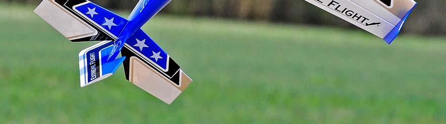
2 Greetings and congratulations on your purchase of the Extreme Flight RC Extra 300EXP ARF. Loosely based on our favorite variant of the Extra, the mid-wing Extra 300, we have taken numerous liberties with this design to produce an aircraft that is both unique in appearance and flight ability. The designation 300EXP does not belong to a full scale Extra, but stands for Experimental Progressive. This name was chosen due to the fact that from its inception the Extra 300EXP was developed as a test bed for several new forward thinking design and aerodynamic concepts. Having spent several months in development, flight testing and refinement, we are very excited about the end result of our quest. The Extra 300EXP incorporates carbon fiber and G10 composites into the structure of the airframe, resulting in a lightweight, yet twist free structure capable of handling extreme aerodynamic loads. Carbon and G10 are used in high stress areas such as motor box support, landing gear mounting structure and fuselage longerons to provide enormous strength and durability. A true piece of carbon fiber art, the landing gear is airfoiled and has just enough "give" to cushion those not so perfect landings. The removable wing panels are mounted on a carbon fiber wing tube and are fastened to the fuselage with nylon thumbscrews. The large canopy (which is retained by a spring loaded hatch latch) has been moved forward to place the tallest portion of the aircraft at the center of gravity, resulting in the best knife edge performance of any aircraft we've flown to date. The airfoiled tail surfaces are built using a unique geodetic construction technique which allows the use of less material while creating a structure that is superior in strength and rigidity to typical ARF construction methods. All control surfaces are pushrod driven with short linkages and use ball links for slop free actuation with no binding. Optional Side Force Generators are included and add to the already generous side area, increasing yaw axis authority and adding stability in all angles of sideslip. Expertly painted fiberglass cowl and wheel pants and 2 gorgeous high visibility Ultracote color schemes add the finishing touches and make this an airplane that you will be proud to show up at the flying field with. The combination of these unique elements add up to an aircraft that pushes the boundaries of modern aerobatic flight. If repairs become necessary, the Ultracote colors used on the Extra 300EXP are as follows: Blue color scheme: Deep Blue/White/Black/Silver Red color scheme: True Red/White/Black/Silver 2
3 Tips for Success: 1. Before starting assembly, take a few minutes to read the entire instruction manual to familiarize yourself with the assembly process. 2. Please take a few minutes and go over all the seams on the aircraft with a covering iron on a medium heat setting. 3. Use a fresh bottle of thin CA with a fine glue tip when attaching the CA hinges. This will ensure that the proper amount of CA wicks into the hinge and surrounding balsa wood and creates a proper bond between the wood and hinges. We are big fans of the Mercury line of adhesives as well as the glue tips provided by them. 4. Apply a couple drops of CA to high stress areas such as anti-rotation pins, landing gear mounts, servo trays and motor box support mounts. 5. All of the G10 control horns are the same with the exception of the elevator horn. Its base has been shortened to fit the width of the elevator. 6. When applying decals, first clean the area where the decal will be applied with alcohol. Mist the area lightly with Windex before applying the decal which will allow you to properly position it, then use a rubber squeegee to push all of the liquid from under the decal. This will result in very few air pockets trapped under the decal. 7. Take the time to properly balance and trim your aircraft and set up rates and exponential values. Your flying experience will be greatly enhanced by doing this. 3
4 Items needed for completion -masking tape -Thin and medium CA. We highly recommend Mercury M5T thin and M100XF medium formulas as well as the Mercury glue tips. -30 minute epoxy. I have used Pacer Z-Poxy for many years and it is a terrific product. It cures in the allotted time and forms a permanent bond. -Blue Loctite. -Silicon based glue (Zap-A-Dap-A-Goo, etc.) -Electric drill with an assortment of small drill bits. -Small flat head and Phillips head screw drivers. -Standard and needle nose pliers. -Metric balldriver or allen key set. -4 sub micro metal geared servos. All flight testing was performed with Hitec HS-65MG and HS-5065MG digital servos and we strongly recommend the use of either of these high quality servos. -Torque 2818T/900 or 2814T/820 Brushless Outrunner motor. -Airboss Elite 45 Amp ESC. -4S mah LiPo battery. Our favorite batteries in this aircraft have been the FlightPower EON Lite We've also had great success with the Zippy Rhino bargain LiPos available from in both 2170 mah and 2350 mah sizes. -APC 12x6 E prop (NOT the slow fly version!). -52mm Extreme Flight spinner "-24" extensions for the 2 rear servos and 2 6"-8" extensions to go between the receiver and the aileron servo leads. We recommend the 28 or 32 AWG extensions to save weight. -Adhesive backed Velcro and Velcro strap for battery retention. 4


5 Let's begin! 1. So that we don't have to wait for the 30 minute epoxy to dry in a later step, let's go ahead and prepare the 4 carbon fiber pushrods and ball links for later use. Locate the 4 carbon fiber pushrods and 4 micro ball links in the hardware package. Lightly scuff one end of each pushrod. 2. Mix up a small batch of 30 minute epoxy. Dip the scuffed end of each pushrod into the epoxy and insert this end into the ball link with a twisting motion to make sure the epoxy is evenly distributed inside the ball link. Make sure the pushrod is completely inserted into the ball link. 5


6 3. Use a paper towel to wipe away most of the excess epoxy, leaving a small fillet between the carbon pushrod and ball link. Position the pushrods vertically while they cure as illustrated so the fillet remains in position. DO NOT use CA for this bond! 4. Locate the 2 wing panels with ailerons as well as the 2 G10 aileron control horns. Remove the ailerons from the wing and remove the covering over the slot for the aileron horn on the bottom of the aileron with a sharp hobby blade. Make sure you are doing this on the bottom of the aileron! 5. Scuff the portion of the control horn that will be glued into the aileron with sandpaper. 6


7 6. Use a glue tip on your bottle of medium CA and apply glue to the slot as well as to both sides of the control horn. Insert the control horn into the slot and make sure it seats properly against the surface of the aileron. 7


8 7. Remove the covering from the aileron servo location and make sure the hinges are centered in their slots. 8


9 8. Slide the aileron into position on the hinges and secure with several drops of fresh thin CA. This process is much easier and more effective if a fine glue tip is used. Make sure to deflect the surface as pictured while applying the CA. 9. Use the screws provided by the servo manufacturer to secure the aileron servo in the designated location. 1 screw installed in the center hole at each end of the servo is adequate to secure the servo. Make sure the output shaft is positioned toward the trailing edge of the wing. 9


10 10. Use a 5/64" drill bit to enlarge the outermost hole in the nylon servo arm that is provided with the servo. Use the longest arm included. Locate one of the EZ connectors and insert the shaft of the connector into the 5/64" hole. A drop of oil placed on the shaft of the connector will ensure that it moves freely within the hole. Place the retaining nut on the threaded portion of the connector shaft and screw down until tight, then back off the nut just enough to allow the connector to turn freely. Place a single drop of CA on the end of the threaded shaft to prevent the nut from coming off. 10


11 11. Two of the carbon pushrod/ball link assemblies are the same size. These are the aileron pushrods. In addition locate 2 silver 2 mm screws, washers and nuts from the hardware package. Secure the ball link side of the pushrod to the aileron control horn on the side of the horn that will be closest to the fuselage by inserting a 2mm bolt into a washer, then through the hole in the brass ball and finally through the hole in the G10 control horn. Place a washer onto the screw and secure with a 2mm nut. Be sure to use a drop of blue Loctite to prevent the nut from backing off of the screw. Electronically center your servo and attach the servo arm with the EZ connector that you pre-fabricated in a previous step. Insert the carbon pushrod into the hole in the EZ connector. This process is probably better explained in the following series of pictures. 11


12 12. Secure the carbon pushrod to the EZ connector with the provided set screw. Take care not to over tighten the set screw and crush the carbon rod. Once you feel the set screw engage the carbon pushrod another 3/4 to 1 turn will supply adequate pressure to retain the pushrod. Make sure that the servo arm is perpendicular to the servo case when the aileron is in the neutral position. 12


13 Here is a photo of the completed installation. Repeat this process for the other wing half. 13


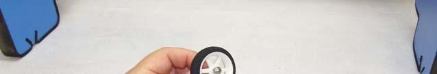
14 13. Locate the fuselage, one piece carbon fiber landing gear, 2 silver 3mm machine screws and 2 washers. Secure the landing gear to the fuselage by inserting a 3mm screw into a washer, through the carbon fiber gear and into the pre-installed blind nut in the fuselage. Make sure to use a drop of blue Loctite on each screw to prevent them from backing out. 14. Locate the 2 axles, 2 locking nuts, 2 wheels, 2 wheel collars and 2 wheel pants from the hardware package. Place the wheel onto the axle and secure with a wheel collar. Place the threaded portion of the axle through the hole in the carbon gear and screw the lock nut onto the axle, but do not tighten completely. There is a slot pre-cut in the wheel pant to allow it to fit over the axle. Before installing the wheel pant place a drop of silicon based glue onto the wheel pant just above the pre-cut slot. This will prevent the wheel pant from rotating, but allow it to move in the case of a mishap which may help to prevent damage. Slide the wheel pant into position over the axle and tighten the nut on the axle, taking care to make sure the wheel pant is positioned properly. Repeat this process for the remaining wheel pant. Again this is probably better explained in the following series of pictures. 14


15 15


16 15. Locate the horizontal stabilizer/elevator assembly and slide the elevator off of the hinges. Insert the stabilizer into its slot and the carbon fiber wing tube into the fiberglass sleeve. Use a ruler to insure that the stabilizer is centered in its slot and compare the stabilizer to the wing tube to make sure it is properly aligned. Sand or shim the slot if necessary. Secure the stabilizer with CA. 16. Remove the covering over the left slot on the bottom of the elevator where the elevator control horn will be installed. The elevator horn is the one with the shortest shank that is glued into the surface. Scuff the portion of the control horn that will insert into the elevator with sandpaper. Secure the control horn with medium CA. 16


17 17


18 17. Slide the elevator onto the hinges in the stabilizer and secure with thin CA. Again a fresh bottle of CA and a fine glue tip work best here. 18. Remove the covering over the slot in the lower left side of the rudder where the rudder control horn will be installed. Scuff the portion of the control horn that will glue into the surface and secure the rudder control horn with medium CA. 18


19 19. Using the same process as with the ailerons and elevator, slide the rudder onto the hinges and secure to the vertical stabilizer with thin CA. 20. Locate the carbon fiber tailwheel assembly in the hardware package. Secure the tailwheel bracket to the bottom rear of the fuselage with the provided wood screws. Make sure the pivot point of the assembly is over the hinge line of the rudder for best results. 19


20 21. Secure the tiller using the provided screw, but do not over tighten as the tiller should be able to move on the screw as the ruder is deflected. 22. Place the tailwheel wire in the proper position, aligned with the rudder and lock into place with the 2 set screws. 23. Use the hardware provided with the servos to install the rudder and elevator servos in their respective location in the rear of the aircraft. From the pilot's perspective the rudder servo mounts on the left side of the fuselage and the elevator servo mounts on the right side. The elevator servo should have the output shaft toward the rear of the aircraft while the rudder servo output shaft should be toward the front of the aircraft. 20


21 24. The rudder servo linkage assembles and is installed just like the aileron linkage. The previous picture illustrates this installation. For maximum elevator travel we have included a G10 control horn which is bolted to the stock control horn provided with the servo. We have found it easiest to tack glue the G10 arm to the nylon arm and then using the holes in the nylon arm as a guide, drill through the composite arm. Secure the arm with the provided screws and bolts. The remaining portion of the linkage installation is the same as the other control surfaces. 21


22 25. We have included 2 plywood spacers in order to accommodate several motor lengths. If using the Torque 2814T/820 no spacer is required. If using the Torque 2818T/900 glue both of the supplied spacers together and place them between the motor mounting plate and the radial mount supplied with the motor. Mount the motor using the supplied 3mm black socket head cap bolts which are threaded into the blind nuts which are pre-installed in the motor mount plate. Be sure to put a drop of blue Loctite onto each bolt to prevent them from backing out. 22


23 This is a picture of the Torque 2818T/900 installed with the 2 ply spacers in place. Also notice the laser cut baffles. A set of these is included which can be attached to the motor box to improve cooling by directing air over the motor. We have not found this necessary but we have yet to fly the aircraft on a hot summer day. Monitor your motor temperatures and if necessary use the baffles. You will find it necessary to lightly sand the top front of edge of the baffle to allow for proper cowl installation. 23


24 26. For quick, easy and accurate mounting of the cowl we recommend the following method. Tear 4 short pieces of masking tape from a roll. Place each piece of tape on the side of the fuselage so that each piece corresponds with one of the 4 cowl mounting tabs. Use a fine tipped marker to mark the location of the center of each mounting tab. Roll the tape back and slide the cowl into position. Install an Extreme Flight 52mm spinner onto the motor shaft for reference and once satisfied with the cowl position roll the tape back into place and secure the cowl. Use a 1/16" drill bit to drill a hole at the location of the dot on each piece of tape. Remove the tape and secure the cowl with 4 of the included small wood screws that have large heads. Very simple! 24


25 27. There is a laser cut opening in the bottom of the fuselage under the rear of the canopy. Use a sharp hobby knife to remove the covering from this location to allow cooling air to exit the fuselage. 28. Use nylon cable ties or Velcro to secure the ESC to the bottom of the motor box. There is an opening in the cowl just in front of this location to allow cooling air to enter and be directed over the ESC. 29. Place a strip of Velcro onto the battery tray and onto your battery and use a Velcro strap around the battery and tray to prevent the battery from being ejected during high G maneuvers. Mount your receiver on the portion of the battery tray that extends behind the wing tube with Velcro. 25


26 30. Because the spring loaded hatch latch gets used every flight, the covering around this area starts to show wear pretty quick. We have included a piece of pre-cut vinyl to place over the latch area to prevent this. 30. If using the included Side Force Generators now is the time to mount them. Each SFG mounts using 2 small wood screws with large heads and 2 clear plastic washers. There are 2 laser cut holes in each SFG which correspond with 2 laser cut holes in the tip of each wing. Insert the screws into the plastic washers and through the laser cut holes in the SFG. Screw the SFG onto the wing tip. I recommend that you then remove the retaining screws and place a drop of thin CA into each hole in the tip of the wing. Allow to dry and then reinstall the SFG. 26
27 27
28 Set-up and flying tips Start by balancing your aircraft on the center of the carbon fiber wing tube. There is plenty of room on the battery tray to move your battery to achieve this CG location. This is a safe place to start and depending on your flying style you can adjust the position of the battery to alter the CG to accommodate your flying style. For this type of aircraft where I am going to predominantly fly aggressive 3D I typically set the airplane up with a neutral CG, meaning that when the aircraft is flown inverted straight and level it requires no down elevator to maintain altitude. If your flying style leans more toward precision aerobatics then I recommend setting your CG using the 45 degree line test. Fly the aircraft from left to right or right to left, whichever direction you are more comfortable with at 3/4 to full throttle. Pull the aircraft to a 45 degree up line and establish this line and immediately roll the aircraft inverted. Establish this line and let go of the elevator stick. Ideally the aircraft will continue to track on that 45 degree line for several hundred feet before slowly starting to level off. Adjust the position of your battery to achieve this flight condition. Once satisfied with the location of your CG scribe a mark on the battery tray so that you can position the battery in the same location each flight and achieve the same feel and flight characteristics each flight. I also highly recommend taking the time to properly set up your rates and exponential settings. Setting up low rates for precision maneuvers and high rates for aggressive aerobatics and 3D flight will allow you to experience the best attributes of the Extra 300EXP or any aircraft for that matter. The included elevator servo arm will allow for close to 80 degrees of throw! While this is great for really aggressive tumbling maneuvers, positive and negative waterfalls and straight down dropping elevators, it can wreak havoc on stable harriers, especially if you are just learning the maneuver. If your radio will allow I suggest setting up 3 elevator rates or a flight condition that will allow you a rate for precision flying, another for harriers and the majority of 3D maneuvers and a final rate with as much travel as you can get for the crazy tumbles and flips. 28
29 Here are some suggested rates to get started with. These are the rates and exponential values I feel comfortable with. They may feel awkward to you and if so please adjust to your taste. Elevator: Low rate-8-10 degrees; 15-20% Exponential 3D rate degrees; 60-65% Exponential Insane tumble rate: As much as possible! 65-70% Exponential Rudder: Low rate-20 degrees; 45-50% Exponential 3D rate- As much as possible; 80-90% Exponential Aileron: Low rate-15-20%; 40-45% Exponential 3D rate- As much as possible; 70-75% Exponential Again, these are my preferences, adjust to suit your flying style and preferred feel. The Extra 300 EXP is capable of performing the full range of known 3D and precision maneuvers. It is also capable of performing all kinds of crazy aggressive maneuvers that have yet to be named. A great deal of fun and excitement can be had by just gaining some speed and pushing the sticks into new positions and seeing what happens! We've been able to coax all kind of crazy gyroscopic maneuvers out of this airframe. One of my favorites is to gain some speed and while on 3D rates and the "insane" elevator rate simultaneously chop the throttle while giving positive snap inputs (full up, full left aileron, full left rudder). Typically the EXP will perform 3 aggressive positive tumbles flipping over the wing tube before it runs of out inertia. Experiment with different inputs and vary the speed of your entry and see what happens. We can't wait to hear what you come up with! Be sure to get it on video! 29
30 Another strong attribute of the EXP is its knife edge capability. The forward canopy placement gives the aircraft very stable KE performance and when coupled with the SFGs the rudder authority is amazing. Huge round KE loops with backside recovery just above idle are the norm for the EXP. Super slow high alpha KE passes are no problem. The included SFGs can also act as "training wheels" when learning the harrier maneuver. They can help to stabilize the aircraft in high alpha flight and reduce pilot workload which certainly helps when you are learning a new maneuver. Another neat set-up to try is to mix the ailerons to act as spoilerons which move in conjunction with your elevator. This mix commands both ailerons to raise as the elevator raises. I typically use this mix at 100% and put it on a switch so I can turn it on when needed and inhibit it when not needed. Some folks feel this type of mix is somehow taboo. To them I say "open your mind"! Anything that enhances flight characteristics or allows me to perform maneuvers that are otherwise not possible I am totally game to try! This mix allows the most straight down dropping elevators you will ever encounter, insane walls that gain no altitude where the tail of the aircraft is basically thrown under the fuselage and the tightest KE spins I've ever seen. This mix is also another good training tool for learning the harrier maneuver and by experimenting with the amount of spoileron to elevator mix you can actually determine the angle of attack that the EXP will harrier in. The best advice I can offer is to experiment, burn through lots of battery packs and above all have fun! You are in possession of a completely capable airframe whose flying abilities are only limited by your imagination. We have had a blast during the development and testing stages of this aircraft and I sincerely hope the Extra 300EXP provides you with as much joy and excitement as it has for me. See ya at the flying field! 30
YAK-54 EXP. 48 inch Electric ARF
 YAK-54 EXP 48 inch Electric ARF 1 Greetings and congratulations on your purchase of the Extreme Flight RC Yak-54 EXP ARF! Like all of the EXP series, the YAK-54 excels at both 3D and precision maneuvers.
MXS-EXP. 64 Inch Electric ARF Assembly Manual
 MXS-EXP 64 Inch Electric ARF Assembly Manual 1 Please take a few moments to read this instruction manual before beginning assembly. We have outlined a fast, clear and easy method to assemble this aircraft
PANTERA Electric Prop Jet ARF
 PANTERA Electric Prop Jet ARF Copyright 2017 Extreme Flight 1 Greetings and congratulations on your purchase of the SPEED FREAK PANTERA! The PANTERA is the second release from SPEED FREAK and is built
EXTRA 330LX. Specifications: Code: SEA274. Graphics and specifications may change without notice. ASSEMBLY MANUAL
 ASSEMBLY MANUAL EXTRA 330LX Code: SEA274 Graphics and specifications may change without notice. Specifications: Wingspan---------------82.0 in (208.2 cm). Wing area---------------1349.4 sq.in ( 87.1 sq.dm).
51in Aerobatic Series Sukhoi SU-26M Almost-Ready-to-Fly. Instruction Manual. Specifications
 51in Aerobatic Series Sukhoi SU-26M Almost-Ready-to-Fly Instruction Manual Specifications Wingspan: 51.2 in (1300mm) Length: 51.2 in (1300mm) Wing Area: 581 sq in (37.5sq dm) Flying Weight: 3.5 lb (1600g)
83" MXS ARF Instruction Manual Copyright 2012 Extreme Flight RC
 83" MXS ARF Instruction Manual Copyright 2012 Extreme Flight RC 1 Please take a few moments to read this instruction manual before beginning assembly. We have outlined a fast, clear and easy method to
SU-31 PROFILE ELECTRIC ARF ASSEMBLY MANUAL
 SU-31 PROFILE ELECTRIC ARF ASSEMBLY MANUAL 1 TABLE OF CONTENTS Page Aeroworks Contact Information... 3 Introduction.. 4 Kit Contents... 5 Items needed to complete 6 Wing Assembly. 7 Stab Assembly. 10 Flight
Turbinator-2 Build Manual
 Turbinator-2 Build Manual Thank you for your purchase of the Turbinator-2 sport jet by Boomerang RC Jets. This RC Jet IS NOT A TOY and should only be flown and operated by experienced RC Turbine Pilots.
RECOMMENDED MOTOR AND BATTERY SET UP
 SPECIFICATION - Wingspan: 1404mm (55.3in) - Length: 1134mm (44. 6 in) - Flying weight: 3.2-3.4 kg - Covering type: Genuine ORACOVER - Spinner size: scale type (not included) - Radio: 4 channel minimum
Modellbau Lindinger GmbH 74 LASER EXP ARF. Instruction Manual. Copyright 2014 Extreme Flight RC
 74 LASER EXP ARF Instruction Manual Copyright 2014 Extreme Flight RC 1 Please take a few moments to read this instruction manual before beginning assembly. We have outlined a fast, clear and easy method
Lanier R/C F-4 Phantom
 Lanier R/C.40-.46 F-4 Phantom Almost Ready to Fly WARNING! THIS IS NOT A TOY! THIS IS NOT A BEGINNERS AIRPLANE This R/C kit and the model you will build from it is not a toy! It is capable of serious bodily
Instruction Manual. Specifications are subjected to change without notice due to product continuous improvements.
 Instruction Manual Specifications are subjected to change without notice due to product continuous improvements. 1 The Wargo Signature Yak 55 is the realization of my goal to have the perfect 3D and aerobatic
1660mm (65.4 in) 1200mm (47.2 in) 2700gr gr 6 channel - 7 servo standard 46/ 2 stroke or 52/ 4 stroke
 1200mm (47.2 in) 2700gr gr 6 channel - 7 servo standard 46/ 2 stroke or 52/ 4 stroke") Instruction Manual CESSNA-46 1660mm (65.4 in) 1200mm (47.2 in) 2700gr - 3000gr 6 channel - 7 servo standard 46/ 2 stroke or 52/ 4 stroke KIT CONTENTS: We have organized the parts as they come out of the
Instruction Manual CESSNA-46 1660mm (65.4 in) 1200mm (47.2 in) 2700gr - 3000gr 6 channel - 7 servo standard 46/ 2 stroke or 52/ 4 stroke KIT CONTENTS: We have organized the parts as they come out of the
8mm EPP Acrocub. Instruction Manual. Specifications
 8mm EPP Acrocub Instruction Manual Specifications Wingspan: 34.6 in (880mm) Length: 31.5 in (800mm) Wing Area: 213.9 sq in (13.8sq dm) Flying Weight: Approx. 9oz (270g) Dear Customer, www.valuehobby.com/8mm-epp-acrocub.html
AVIATOR 25 ARF Almost Ready-to-Fly
 AVIATOR 25 ARF Almost Ready-to-Fly Instruction Manual Specifications Wingspan: 54.3 in (1380mm) Length: 45.2 in (1150mm) Wing Area: 438 sq in (34sq dm) Flying Weight: 3.8 b (1700g) Dear Customer, Congratulations
ALMOST READY TO FLY. Wing Span in cm. 2
 ASSEMBLY MANUAL ALMOST READY TO FLY MS:X9 Specifications Wing Span --------------------------61.4 in ---------------------------156cm. 2 Wing Area --------------------------606.1 sq.in ------------------
96in Super Decathlon ARF
 96in Super Decathlon ARF Instruction Manual Specifications Wingspan: 96in (2438mm) Length: 63.5 in (1614mm) Weight: Approx. 13lbs (6.5kg) 1 Dear Customer, Congratulations on your purchase of Super Decathlon
I n s t r u c t i o n M a n u a l. Instruction Manual SPECIFICATION
 I n s t r u c t i o n M a n u a l Instruction Manual SPECIFICATION - Wingspan: 3200mm (125,9 in) - Length: 1650mm (64,9 in) - Flying weight: 3000gr 3200gr - Wing area: 64.5 dm2 - Wing loading: 46g/dm2
RECOMMENDED MOTOR AND BATTERY SET UP
 SPECIFICATION - Wingspan: 1410mm (55.5 in) - Length: 1278mm (50.3 in) - Flying weight: 3.2-3.4 kg - Wing area: 41.3 dm2 - Wing loading: 75g/dm2 - Wing type: Naca airfoils - Covering type: Genuine ORACOVER
Instruction Manual. Specification:
 Instruction Manual L O W Specification: Wingspan: 133 cm (52.3 inches) Length : 104 cm (40.9 inches) Weight : 1790gr Engine : 25-32 two stroke Radio : 4 channel - 4 servo W I N G KIT CONTENTS: We have
48in Sbach-342. Instruction Manual. Specifications
 48in Sbach-342 Instruction Manual Specifications Wingspan: 48in (1219mm) Length: 46in (1163mm) Wing Area: 471sq in (30.4sq dm) Flying Weight: 1.8-2.0lb (800-900g) Dear Customer, www.valuehobby.com/48in-s342-arf.html
RECOMMENDED MOTOR AND BATTERY SET UP
 SPECIFICATION - Wingspan: 2000mm (78.7in) - Length: 1544mm (60.7 in) - Flying weight: 3600-3800 gr - Wing area: 66 dm2 - Wing loading: 55g/dm2 - Wing type: Naca airfoils - Covering type: Genuine ORACOVER
Assembly Manual For. Wingspan: 88 in Wing area: sp in Length: 78.8 in Engine: 50CC.
 Assembly Manual For Wingspan: 88 in Wing area: 1479.8 sp in Length: 78.8 in Engine: 50CC www.pilot-rc.com INTRODUCTION Thank you for purchasing our new 50 cc model. We strive to bring you the most complete
RECOMMENDED MOTOR AND BATTERY SET UP
 SPECIFICATION - Wingspan: 6000mm (236.2 in) - Length: 2873mm (113.1 in) - Flying weight: 14-18 kg - Wing area: 219.4 dm2 - Wing loading: 64g/dm2 - Wing type: HQ airfoils - Covering type: Genuine ORACOVER
91" LASER EXP ARF. Assembly Manual. Copyright 2017 Extreme Flight
 91" LASER EXP ARF Assembly Manual Copyright 2017 Extreme Flight 1 Please take a few moments to read this instruction manual before beginning assembly. We have outlined a fast, clear and easy method to
Table of Contents. Tail Wheel Assembly Installation.. page 01. Stabilizer Installation.. page 02. Fin Installation.. page 03
 Table of Contents Tail Wheel Assembly Installation.. page 01 Stabilizer Installation.. page 02 Fin Installation.. page 03 Elevator and Rudder Hinge Installation.. page 04 Rudder Controls.. page 05 Elevator
93 AJ Laser 230z Assembly Instructions
 93 AJ Laser 230z Assembly Instructions Congratulations AJ Aircraft thanks you for the purchase of this airplane. Top grade materials and precision assembly has gone into this to make this a top quality
I/C FLIGHT GUIDELINES
 SPECIFICATION - Wingspan: 3500mm (137.8 in) - Length: 1650mm (64.96 in) - Flying weight: 3700-4000 gr - Wing area: 75 dm2 - Wing loading: 49g/dm2 - Wing type: HQ profile - Covering type: Genuine ORACOVER
SIZE.120 OR 30CC SCALE 1:5 ARF
 PC21 PILATUS MK2 SIZE.120 OR 30CC SCALE 1:5 ARF SPECIFICATION - Wingspan: 1772mm (69.72in) - Length: 2019mm (79.5 in) - Flying weight: 6.4-7.2 kg - Wing area: 57.6 dm2 - Wing loading: 113g/dm2 - Wing type:
RECOMMENDED MOTOR AND BATTERY SET UP
 SPECIFICATION - Wingspan: 1800mm (70.8 in) - Length: 1355mm (53.3 in) - Flying weight: 4100-4300 g - Wing area: 51 dm2 - Wing loading: 80g/dm2 - Wing type: Naca airfoils - Covering type: Genuine ORACOVER
MX2 100CC & MXS-R 100CC Giant Scale Aerobatic Aircraft
 MX2 100CC & MXS-R 100CC Giant Scale Aerobatic Aircraft By the act of using the final assembled model, the purchaser/operator accepts all resulting liability. Included Features: Fuselage and Wing incorporate
Gent EPP. Before use please read the explanations carefully
 Before use please read the explanations carefully Gent EPP Instruction Manual Specifications Fuselage length 900mm 35in Wingspan 820mm 32in Flying Weight 210 240g with battery Additional Required Equipment
SBACH SCALE 1:4 ½ ARF
 SPECIFICATION - Wingspan: 1663mm (65.5 in) - Length: 1638mm (64.5 in) - Flying weight: 4700-5200 gr - Wing area: 56 dm2 - Wing loading: 85g/dm2 - Wing type: Naca airfoils - Covering type: Genuine ORACOVER
HIGH WING MK2 GP/EP ARF SCALE
 SONIC HIGH WING MK2 GP/EP.25-.32 ARF SCALE 1:10 SPECIFICATION - Wingspan: 1340mm (52.7in) - Length: 1040mm (40.9 in) - Flying weight: 1800-2000 gr - Wing area: 27 dm2 - Wing loading: 79g/dm2 - Wing type:
YAK-55M 1.8. Forget the rest - a YAK ist the best! Assembly instructions. Gernot
 YAK-55M 1.8 Assembly instructions Forget the rest - a YAK ist the best! Gernot Table of contents 1.Specifications (metric units)...2 2.Recommended Setups...2 3.Required tools and adhesives:...2 4.Warning...3
Gasoline powered. Congratulations on your purchase of this excellent almost-ready-to-fly R/C
 Gasoline powered Congratulations on your purchase of this excellent almost-ready-to-fly R/C Congratulations on on your your purchase purchase of this of this excellent excellent almost-ready-to-fly almost-ready-to-fly
MARACANA ASSEMBLY INSTRUCTION .40 ARF LOW WING TRAINER RADIO CONTROL MODEL. Every body can fly
 RADIO CONTROL MODEL ASSEMBLY INSTRUCTION MARACANA.40 ARF LOW WING TRAINER Every body can fly VQA085 EP GP You can use both Gas or Electric power Wingspan: 59in.(1520mm) Fuselage length: 48in.(1220mm) Engine:
RECOMMENDED MOTOR AND BATTERY SET UP
 SPECIFICATION - Wingspan: 1420mm (55.91 in) - Length: 1370mm (53.94 in) - Flying weight: 2600-2800 gr - Wing area: 41.6 dm2 - Wing loading: 65g/dm2 - Wing type: Naca airfoils - Covering type: Genuine ORACOVER
Instruction Manual. Item No: AL506
 Instruction Manual Item No: AL506 Specifications: Wingspan: 2218mm (87.3 in) Length: 1892mm (74.5 in) Wing Area: 100dm2 (1550 sq in) Flying Weight: 7.3kg (16.1 lbs) Engine(not incl.): 50-60cc Gas Radio(not
RECOMMENDED MOTOR AND BATTERY SET UP
 SPECIFICATION - Wingspan: 2190mm (86.2 in) - Length: 1907mm (75 in) - Flying weight: 9000-12000 gr - Wing area: 92 dm2 - Wing loading: 98g/dm2 - Wing type: Naca airfoils - Retract gear type: Air-retract
Instruction Manual. Wingspan : 1884 mm (74.17 in) Length. Weight. Engine. : 4 channels / 5 servo standard. : 1450 mm (57.
 Length. Weight. Engine. : 4 channels / 5 servo standard. : 1450 mm (57.") Wingspan : 1884 mm (74.17 in) Length : 1450 mm (57.09 in) Weight : 4000 gr Engine : 60 two strokes Radio : 4 channels / 5 servo standard KIT CONTENTS: We have organized the parts as they come out of the
Wingspan : 1884 mm (74.17 in) Length : 1450 mm (57.09 in) Weight : 4000 gr Engine : 60 two strokes Radio : 4 channels / 5 servo standard KIT CONTENTS: We have organized the parts as they come out of the
Super Chipmunk 20-30CC Manual. Instruction Manual
 ARF MODEL Super Chipmunk 20-30CC Manual Instruction Manual Dear Customer, Thank you for purchasing this excellent almost-ready to fly R/C model. This plane is to be powered by 20-30CC gas engine. It can
Assembly Manual For. Wingspan: 88 in Wing area: sp in Length: 78.8 in Engine: 50CC.
 Assembly Manual For Wingspan: 88 in Wing area: 1479.8 sp in Length: 78.8 in Engine: 50CC www.pilot-rc.com INTRODUCTION Thank you for purchasing our new 50 cc model. We strive to bring you the most complete
MEMO. No.4341 Specification: Wing Span: 29.1 (740mm) Length: 36.6 (930mm) 2. Warranty
 Length: 36.6 (930mm) 2. Warranty") MEMO No.4341 Specification: Wing Span: 29.1 (740mm) Length: 36.6 (930mm) 2 Wing Area: 299 sq.in. (19.29 dm ) Weight: 18.9oz. (536.5g) 2 Wing loading: 0.58 oz./sq.ft (27.8g/dm ) Motor: OBL 29/27-07A Warranty
MEMO No.4341 Specification: Wing Span: 29.1 (740mm) Length: 36.6 (930mm) 2 Wing Area: 299 sq.in. (19.29 dm ) Weight: 18.9oz. (536.5g) 2 Wing loading: 0.58 oz./sq.ft (27.8g/dm ) Motor: OBL 29/27-07A Warranty
ALMOST READY TO FLY. Wing Span in cm. 2
 ASSEMBLY MANUAL ALMOST READY TO FLY MS: X12 A - B Graphics and specfications may change without notice. Kit features. Specifications Wing Span ------------------------------- 42.7 in ---------------------
F3P Instruction Manual
 Before use, please read the explanations carefully! F3P Instruction Manual Specifications Fuselage length: 884mm ( 34. Bin ) Wingspan : 845mm ( 33. 2in) Flying Weight : 135-160g (with battery) Additional
Instruction Manual. Wingspan : 1694mm (66.69 in) : 1470mm (57.87 in) : 3200gr gr. : 61 two stroke/ 71 four stroke. : 6 channel / 7 servo
 : 1470mm (57.87 in) : 3200gr gr. : 61 two stroke/ 71 four stroke. : 6 channel / 7 servo") Wingspan : 1694mm (66.69 in) g Length : 1470mm (57.87 in) Weight : 3200gr - 3800gr Engine : 61 two stroke/ 71 four stroke Radio : 6 channel / 7 servo KIT CONTENTS: We have organized the parts as they
Wingspan : 1694mm (66.69 in) g Length : 1470mm (57.87 in) Weight : 3200gr - 3800gr Engine : 61 two stroke/ 71 four stroke Radio : 6 channel / 7 servo KIT CONTENTS: We have organized the parts as they
Instruction Manual. Wingspan : 1400mm (55.12 in) : 1370mm (53.94 in) : 2600gr gr. : 4 channel / 5 servo. : / 2 stroke_52-71 / 4 stroke
 : 1370mm (53.94 in) : 2600gr gr. : 4 channel / 5 servo. : / 2 stroke_52-71 / 4 stroke") Instruction Manual 540 Wingspan : 1400mm (55.12 in) g Length : 1370mm (53.94 in) Weight : 2600gr - 2800gr Radio : 4 channel / 5 servo Engine : 46-52 / 2 stroke_52-71 / 4 stroke KIT CONTENTS: We have organized
Instruction Manual 540 Wingspan : 1400mm (55.12 in) g Length : 1370mm (53.94 in) Weight : 2600gr - 2800gr Radio : 4 channel / 5 servo Engine : 46-52 / 2 stroke_52-71 / 4 stroke KIT CONTENTS: We have organized
FUN-50 ARF ASSEMBLY MANUAL
 FUN-50 ARF ASSEMBLY MANUAL This Manuel is the sole property of Kangke Industrial USA, Inc. Reproducing any part without the consent of Kangke Industrial USA, Inc. is a lawful violation. Kangke Industrial
YAK54 MK2. GP/EP size.120/20cc SCALE 1:4 ¾ ARF. Instruction Manual. version. version
 Instruction Manual GP EP version version GP/EP size.10/0cc SCALE 1:4 ¾ ARF SPECIFICATION - Wingspan: 168 (66.3 in) - Length: 1605mm (63.1 in) - Flying weight: 4700-500 gr - Wing area: 54.7 dm - Wing loading:
MS:159 ASSEMBLY MANUAL. Graphics and specifications may change without notice.
 ASSEMBLY MANUAL MS:159 Graphics and specifications may change without notice. Specifications: Wing span ----------------------------61.8in (157cm). Wing area -----------------1100.5sq.in (71.0sq dm). Weight
HERO 3D SCALE 1:6 ARF
 Instruction Manual SPECIFICATION - Wingspan: 1500mm(59 in) - Length: 1410mm (55.5 in) - Flying weight: 2100-2300 gr - Wing area: 58 dm2 - Wing loading: 39g/dm2 - Covering type: Genuine ORACOVER - Gear
RECOMMENDED EDF AND BATTERY SET UP
 SPECIFICATION - Wingspan: 1150mm (45.3 in) - Length: 1587mm (62.5 in) - Flying weight: 5.0-5.3 kg - Wing area: 40dm2 - Wing loading: 125g/dm2 - Wing type: Naca airfoils - Covering type: Genuine ORACOVER
RECOMMENDED MOTOR AND BATTERY SET UP
 SPECIFICATION - Wingspan: 1600mm (63 in) - Length: 1285mm (50.5 in) - Flying weight: 2800-3200 gr - Wing area: 40.1 dm2 - Wing loading: 78g/dm2 - Wing type: Naca airfoils - Covering type: Genuine ORACOVER
RADIO CONTROL MODEL HURRICANE
 RADIO CONTROL MODEL VQAA040G VQAA040B HURRINE Almost ready to fly SPECIFITIONS Wingspan...63 in. / 161cm Length...50 in. / 129cm Engine...50~60 2T / 70~90 4T Or Electric equivalent. RC Functions: Motor
RECOMMENDED MOTOR AND BATTERY SET UP
 SPECIFICATION - Wingspan: 1669mm (65.7in) - Length: 1229mm (48.43 in) - Flying weight: 3300-3400 gr - Wing area: 44.2 dm2 - Wing loading: 67g/dm2 - Wing type: Naca airfoils - Covering type: Genuine ORACOVER
(Glider) ASSEMBLY MANUAL
 ASSEMBLY MANUAL") (Glider) MS:132 ASSEMBLY MANUAL Graphics and specifications may change without notice. Specifications: Wing span ------------------------------118.1in (300cm). Wing area ---------------------902.1sq.in
(Glider) MS:132 ASSEMBLY MANUAL Graphics and specifications may change without notice. Specifications: Wing span ------------------------------118.1in (300cm). Wing area ---------------------902.1sq.in
the leading edge of the wing, at the fuselage - Length: 1540mm (60.6 in) 10% expo; High: 15mm up/down, 10% expo - Wing area: 40dm2
 10% expo; High: 15mm up/down, 10% expo - Wing area: 40dm2") SPECIFICATION - Gravity CG: 165-170 mm (6.5-6.7 in) Back from - Wingspan: 1400mm (55.1 in) the leading edge of the wing, at the fuselage - Length: 1540mm (60.6 in) - Control throw Ailerons: Low: 12mm up/down,
SPECIFICATION - Gravity CG: 165-170 mm (6.5-6.7 in) Back from - Wingspan: 1400mm (55.1 in) the leading edge of the wing, at the fuselage - Length: 1540mm (60.6 in) - Control throw Ailerons: Low: 12mm up/down,
MS:176 ASSEMBLY MANUAL. Graphics and specifications may change without notice.
 ASSEMBLY MANUAL MS:176 Graphics and specifications may change without notice. Specifications: Wing span ------------------------------98.4in (250cm). Wing area ----------------1576.4sq.in (101.7sq dm).
to fly. Most hardware included and all replacement parts are available.
 Instruction Manual The Thunderbolt P47 was perhaps the greatest of world war II in terms of all round performance and capability Phoenix Model has recreated a 2C - 60 class engine (or 4c 91 class) It was
Instruction Manual. Wingspan : 1400 mm (55.12 inch) : 1480 mm (58.27 inch) : 5500gr gr. : 6-9 channel/ 8 servo high torque,1 standard
 : 1480 mm (58.27 inch) : 5500gr gr. : 6-9 channel/ 8 servo high torque,1 standard") Wingspan : 1400 mm (55.12 inch) g Length : 1480 mm (58.27 inch) Weight : 5500gr - 6000gr Radio : 6-9 channel/ 8 servo high torque,1 standard Engine : GT 22 OS KIT CONTENTS: We have organized the parts
Wingspan : 1400 mm (55.12 inch) g Length : 1480 mm (58.27 inch) Weight : 5500gr - 6000gr Radio : 6-9 channel/ 8 servo high torque,1 standard Engine : GT 22 OS KIT CONTENTS: We have organized the parts
... BY: Scott Barnhart
 Wi! ;ql ;~,... TEe ONEYAII54...................................................................................... BY: Scott Barnhart I TALK UP TmSYAK Techone Hobby is a company schemes. The computer numeric
RECOMMENDED MOTOR AND BATTERY SET UP
 Instruction Manual SPECIFICATION - Wingspan: 1418mm (55.8 in) - Length: 1314mm (51.7 in) - Flying weight: 2700-3200 gr - Wing area: 36.8 dm2 - Wing loading: 76g/dm2 - Wing type: Naca airfoils - Covering
29% KATANA ARF ASSEMBLY MANUAL
 29% KATANA ARF ASSEMBLY MANUAL Required but not included Aircraft Specifications: 4 channel radio and supporting equipment Wing Span 84 Engine 3.2-4.2 c.i. (50-60 c.c.) Wing Area 1270 Sq. in. Fuel Tank
Instruction Manual. Wingspan : 2270mm (89.37 inches) : 1870mm (73.62 inches) : 7400gr gr. : 4 channel - 6 standard servo.
 : 1870mm (73.62 inches) : 7400gr gr. : 4 channel - 6 standard servo.") Wingspan : 2270mm (89.37 inches) g Length : 1870mm (73.62 inches) Weight : 7400gr - 7600gr Radio : 4 channel - 6 standard servo Engine : 25cc-35cc KIT CONTENTS: We have organized the parts as they come
Wingspan : 2270mm (89.37 inches) g Length : 1870mm (73.62 inches) Weight : 7400gr - 7600gr Radio : 4 channel - 6 standard servo Engine : 25cc-35cc KIT CONTENTS: We have organized the parts as they come
ASSEMBLY MANUAL SIZE: 46-62
 SIZE: 46-62 MS:199 ASSEMBLY MANUAL Graphics and specifications may change without notice. Specifications: Wing span ------------------------------54.9 in ( 139.5cm). Wing area -----------------517.7 sq.in
STORCH. Parts. Additional items needed to complete the Storch
 STORCH Parts Fuse with Greenhouse- (Attached) Left and right wing panel Horizontal and vertical stab 2 Wing center blocks 2 Carbon spares for wing 1 Undercarriage with wheels 2 Undercarriage shocks 2 Carbon
Aviator Pro 120 ARF. Instruction Manual. Specifications
 Aviator Pro 120 ARF Instruction Manual Specifications Wingspan: 110 in (2800 mm) Length: 74 in (1870 mm) Wing Area: 1581sq in (102 sq dm) Weight: 11.4-13.4 lbs (5190-6100 g) Dear Customer, Congratulations
MEMO. Assembly Manual. No Specification: Wing Span: 29.3 (830mm) Length: 29.8 (845mm) 2. Warranty
 Length: 29.8 (845mm) 2. Warranty") MEMO Assembly Manual No. 4347 Specification: Wing Span: 29.3 (830mm) Length: 29.8 (845mm) 2 Wing Area: 322.4 sq.in. (20.8 dm ) Weight: 14oz.~15oz. (420~430g) Warranty This kit is guaranteed to be free
MEMO Assembly Manual No. 4347 Specification: Wing Span: 29.3 (830mm) Length: 29.8 (845mm) 2 Wing Area: 322.4 sq.in. (20.8 dm ) Weight: 14oz.~15oz. (420~430g) Warranty This kit is guaranteed to be free
SK-50 ARF ASSEMBLY MANUAL
 SK-50 ARF ASSEMBLY MANUAL Kangke Industrial USA, Inc. 65 East Jefryn Blvd. Deer Park NY 11729 http://www.kangkeusa.com E-mail: info@kangkeusa.com Tel: 1-877-203-2377 Fax: 1-631-274-3296 Congratulations!
Instruction Manual book
 book ITEM CODE:BH 115. SPECIFICATION Wingspan : 6,000 mm 236,22 in. Length : 2,740 mm 107,87 in. Weight : 17.5kg 38.5Lbs. Radio : 08 channels. Servo : 07-08 HS-5685MH(HITEC) Battery : 2 Cells-Li-Po 7.4V
ASSEMBLY MANUAL
 www.seagullmodels.com MS: X104 ASSEMBLY MANUAL Graphics and specifications may change without notice. Specifications: Wing span ----------------- 35.4in (90.0cm). Wing area ------------------392.2sq.in
MEMO. Assembly Manual. No Specification: Wing Span: 29.3 (830mm) Length: 29.8 (845mm) 2. Warranty
 Length: 29.8 (845mm) 2. Warranty") MEMO Assembly Manual No. 4347 Specification: Wing Span: 29.3 (830mm) Length: 29.8 (845mm) 2 Wing Area: 322.4 sq.in. (20.8 dm ) Weight: 14oz.~15oz. (420~430g) Warranty This kit is guaranteed to be free
MEMO Assembly Manual No. 4347 Specification: Wing Span: 29.3 (830mm) Length: 29.8 (845mm) 2 Wing Area: 322.4 sq.in. (20.8 dm ) Weight: 14oz.~15oz. (420~430g) Warranty This kit is guaranteed to be free
GOLDWING RC 68in SLICK540 20CC & 90E Instruction Manual Two version to choice: 90 Electric or 20CC
 GOLDWING RC 68in SLICK540 20CC & 90E Instruction Manual Two version to choice: 90 Electric or 20CC Dear Customer, Thanks for purchasing this newly designed aerobatic RC airplane. Goldwing RC proudly presents
Build Manual. Vector & Xtra Slick
 Build Manual Vector & Xtra Slick Warning information this is not a toy! Read and understand entire manual before assembling model Do not overlook the warnings and instructions enclosed or those provide
RADIO CONTROL MODEL ASSEMBLY INSTRUCTIONS. Wasp
 RADIO CONTROL MODEL ASSEMBLY INSTRUCTIONS Wasp TRAINER Almost ready-to-fly Wingspan 1520mm Fuselage length 1105mm Engine: 40-46 2T / 52-60 4T Electric Motor: 600-700W Radio: 5 channel / 4-5 servo RC Functions:
SBD DAUNTLESS GP/EP SIZE ARF SCALE 1:8. Instruction Manual
 GP/EP SIZE.46-.55 ARF SCALE 1:8 SPECIFICATION - Wingspan: 1440mm (56.7in) - Length: 1140mm (44.9 in) - Flying weight: 3000-3300 g - Wing area: 42 dm2 - Wing loading: 78g/dm2 - Wing type: Naca airfoils
GoldWing RC. PIPER J3 50CC Giant Scale Aircraft
 GoldWing RC PIPER J3 50CC Giant Scale Aircraft Specifications Wing Span: 119"(3030mm) Length: 79-1/4"(2015mm) Wing Area: 2055sq in(132.6sq dm) Flying Weight: 18.7-22lbs(8.5-10kg) Gas: 50CC-70CC Gas DLE55,
: 6 channel - 9 servo
 g Wingspan : 2005mm (78.94 inches) Length : 1640mm (64.57 inches) Weight : 6400g - 6600g Engine : 25cc - 35cc Radio : 6 channel - 9 servo KIT CONTENTS: We have organized the parts as they come out of
CAP 232 ASSEMBLY MANUAL
 CAP 232 MS: ASSEMBLY MANUAL SEA 91 Graphics and specfications may change without notice. Specifications Wingspan------------------------------------ 65 in --------------------------------- 165cm. Wing
Pitts Challenger m (100cc) MANUAL
 MANUAL") Pitts Challenger 87 2.20m (100cc) MANUAL 1- Introduction: WELCOME TO THE PILOT-RC TEAM! Thank you for choosing a Pilot-Rc plane as your next model. We hope that you enjoy many successful and exhilarating
Pitts Challenger 87 2.20m (100cc) MANUAL 1- Introduction: WELCOME TO THE PILOT-RC TEAM! Thank you for choosing a Pilot-Rc plane as your next model. We hope that you enjoy many successful and exhilarating
STICK F Class 60 Class INSTRUCTION MANUAL. Or Electric equivalent. (2T engine) (4T engine) Radio control model SPECIFICATIONS
 (4T engine) Radio control model SPECIFICATIONS") Radio control model 45 Class 60 Class (2T engine) (4T engine) Or Electric equivalent INSTRUCTION MANUAL STICK F - 1500 SPECIFICATIONS Wingspan 60 in. Length 38.5 in. Electric Motor 650 Watt Glow Engine.45
Radio control model 45 Class 60 Class (2T engine) (4T engine) Or Electric equivalent INSTRUCTION MANUAL STICK F - 1500 SPECIFICATIONS Wingspan 60 in. Length 38.5 in. Electric Motor 650 Watt Glow Engine.45
 WWW.SEAGULLMODELS.COM ASSEMBLY MANUAL Graphics and specifications may change without notice. Code: SEA249 (SEA249M) (SEA249D) Specifications: www.seagullmodels.com Wingspan---------------70.9 in (180 cm).
ARF. Specifications: ASSEMBLY MANUAL MS: 193. Graphics and specifications may change without notice.
 ASSEMBLY MANUAL Graphics and specifications may change without notice. MS: 193 ARF Specifications: Wingspan---------------62.0 in (157.5 cm). Wing area----------------620 sq.in (40.0 sq.dm). Weight-------------------3.3-3.9
MS:183 ASSEMBLY MANUAL. Graphics and specifications may change without notice.
 MS:183 ASSEMBLY MANUAL Graphics and specifications may change without notice. Specifications: Wing span ------------------------------79.9in (203cm). Wing area -----------------1165.6sq.in (75.2sq dm).
MS:190 ASSEMBLY MANUAL. Graphics and specifications may change without notice.
 ASSEMBLY MANUAL MS:190 Graphics and specifications may change without notice. Specifications: Wing span -----------------------------49.2.in (125cm). Wing area -----------------415.4sq.in (26.8sq dm).
ASSEMBLY MANUAL. Graphics and specifications may change without notice.
 NEMESISMS: SEA 111 ASSEMBLY MANUAL Graphics and specifications may change without notice. Specifications Wing span------------------------------------- 55.9in ------------------------------- 142cm. Wing
Trainer Assembly Manual
 Trainer Assembly Manual www.pilot-rc.com -Pilot Trainer- 1 -Pilot Trainer- 2 -Pilot Trainer- 3 -Preliminary i wing & stab assembly- 1-) Locate both Plywood wing joiners (Large and small one) 2-) Insert
MS:167 ASSEMBLY MANUAL. Graphics and specifications may change without notice.
 ASSEMBLY MANUAL MS:167 Graphics and specifications may change without notice. Specifications: Wing span ------------------------------66.9in (170cm). Wing area -----------------764.2sq.in (49.3sq dm).
ARF TRAINER KIT ASSEMBLY MANUAL BOOMERANG EP. ALMOST READY TO FLY
 WWW.SEAGULLMODELS.COM ASSEMBLY MANUAL BOOMERANG EP ARF TRAINER KIT Graphics and specifications may change without notice. MS: 211 ALMOST READY TO FLY Specifications: Wingspan---------------56.0 in (142.2
Instruction Manual book
 book SPECIFICATION Wingspan : 1,450 mm 57.09 in. Length : 1,200mm 47.24in. Weight : 3.1 kg 6.82 Lbs. Radio : 05 channels. Servo : 07 servos. Engine : 61-75 2 stroke. 91 4 stroke. Made in Vietnam. This
RECOMMENDED MOTOR AND BATTERY SET UP
 SPECIFICATION - Wingspan: 2567mm (101in) - Length: 2190mm (86.2 in) - Flying weight: 11-13 kg - Wing area: 101 dm2 - Wing loading: 99g/dm2 - Wing type: Naca airfoils - Covering type: Genuine ORACOVER -
MS:174 ASSEMBLY MANUAL. Graphics and specifications may change without notice.
 MS:174 ASSEMBLY MANUAL Graphics and specifications may change without notice. Specifications: Wing span ------------------------------79.9in (203cm). Wing area -----------------911.4sq.in (58.8sq dm).
: 7 channel - 9 servo, Hi-Torque ( Minimum 6 kg ).
.") g Wingspan : 1820mm (71.65 inches) Length : 1625mm (63.98 inches) Weight : 6900gr Engine : 25cc - 35cc Radio : 7 channel - 9 servo, Hi-Torque ( Minimum 6 kg ). KIT CONTENTS: We have organized the parts
g Wingspan : 1820mm (71.65 inches) Length : 1625mm (63.98 inches) Weight : 6900gr Engine : 25cc - 35cc Radio : 7 channel - 9 servo, Hi-Torque ( Minimum 6 kg ). KIT CONTENTS: We have organized the parts
SIZE 55 ASSEMBLY MANUAL
 SIZE 55 ASSEMBLY MANUAL MS:120 Graphics and specifications may change without notice. Specifications: Wing span ------------------------------63in (160cm). Wing area -----------------643.3sq.in (41.5sq
SUPER KRAFT Rearwin Speedster Assembly Manual
 SUPER KRAFT Rearwin Speedster Assembly Manual KANGKE INDUSTRIAL USA Inc. 65 East Jefryn Blvd. Deer Park New York 11729 http://www.kangkeusa.com E-mail: info@kangkeusa.com 1-877-203-2377 Fax 1-631-274-3296
PilotRC Trainer USER MANUAL
 PilotRC Trainer USER MANUAL Introduction Thank you for purchasing our Trainer plane. we strive to achieve a good quality quick build ARF aircraft. It requires the least amount of assembly of any ARF kit
Instruction Manual book
 book Item code:bh131 SPECIFICATION Wingspan : 3,000 mm 118.1 in. Length : 1,600 mm 62.99 in. Weight : 2.2 kg 4.84 Lbs. Radio : 05 channels. Servo : 06 mini servos. Electric Motor: BOOST 40 Battery : 3celIs
 WWW.SEAGULLMODELS.COM ASSEMBLY MANUAL Graphics and specifications may change without notice. Code: SEA232 Specifications: Wingspan---------------70.9 in (180 cm). Wing area---------------810.3 sq.in (52.3
70MM YAK-130 STABLE SMOOTH FLYING PERFORMANCE FMSMODEL.COM
 70MM YAK-130 REALISTIC RETRACT & FLAPS INSTALLED RIGID STRONG DURABLE EPO STABLE SMOOTH FLYING PERFORMANCE FMSMODEL.COM Table of Contents Introductions 3 Contents of Kit 4 Assemble the plane 5 Battery