this manual Covers all units shipped 2015 to date
|
|
|
- Myrtle Daniels
- 6 years ago
- Views:
Transcription

1 installation and owner s manual this manual Covers all units shipped 2015 to date printed in u.s.a. publication no rev. 7 rite-hite print shop July 2015
2 table of Contents SAFETY WARNINGS PHOTOS OF DOOR DEPUTY MECHANISM TOOLS REQUIRED INSTALLATION OF HOLD-OPEN TM MECHANISM MOUNTING DOOR DEPUTY CATCH INSTALLATION OF DOOR DEPUTY ROLLER GUARD INSTALLATION OF LOCk-DOWN TM MECHANISM ADJUSTMENTS INTERLOCk SWITCH DOOR DEPUTY PARTS TROUBLE SHOOTING WARRANTY product introduction Thank you for purchasing the DOOR DEPUTY from RITE-HITE. important Read and understand contents of this manual prior to installation or operation of this equipment. For best results, have this product serviced by your authorized RITE-HITE. notice to user Your local RITE-HITE Representative provides the Planned Maintenance Program (P.M.P.) which can be fitted to your specific operation. Call your local representative or RITE-HITE at or toll free at The RITE-HITE products in this manual may be covered by one or more of the following U.S. patents: 4,560,315 (RE: 32,968); 4,634,334; 4,692,755; 4,744,121; 4,819,770; 4,843,373; 4,865,507; 4,920,598; 4,995,130; 5,040,258; 5,111,546; 5,212,846; 5,271,183; 5,299,386; 5,311,628; 5,323,503; 5,375,965; 5,440,772; 5,442,825; 5,453,735; 5,531,557; 5,546,623; 5,553,987; 5,582,498; 5,664,930; 5,702,223; 5,762,459 (RE: 37,570); 5,882,167; 5,964,572; 6,010,297; 6,052,268; 6,065,172; 6,070,283; 6,074,157; 6,085,375; 6,092,970; 6,106,212; 6,116,839; 6,190,109; 6,220,809; 6,627,016; 6,238,163; 6,322,310; 6,311,352; 6,360,394; 6,368,043, 6,431,819; 6,488,464; 6,497,067; 6,499,169; 6,505,713; 6,524,053; 6,634,049; 6,654,976; 6,676,360; and pending U.S. and foreign patent applications. RITE-HITE, LEVEL-RITE, THINMAN T M, SAFE-T-LIP, HYDRACHEK, WHEEL-LOK T M, DOK-, DUAL-DOK, SAFE-T-STRUT T LOK M, DOK-COMMANDER, JUMBO TM and SAFE-T-GATE are trademarks of RITE-HITE. 2 pub. no rev. 7 - July 2015
3 safety warning when working with electrical or electronic controls, make sure that the power source has been locked out and tagged according to osha regulations or your country s local standards and approved local electrical codes. Figure 1 lockout / tagout procedures The Occupational Safety and Health Administration (OSHA) requires that, in addition to posting safety warnings and barricading the work area, the power supply has been locked in the OFF position or disconnected. It is mandatory that an approved lockout device is utilized. An example of a lockout device is illustrated in Figure 1. The proper lockout procedure requires that the person responsible for the repairs is the only person who has the ability to remove the lockout device. In addition to the lockout device, it is also a requirement to tag the power control in a manner that will clearly note that repairs are under way and state who is responsible for the lockout condition. Tagout devices have to be constructed and printed so that exposure to weather conditions or wet and damp locations will not cause the tag to deteriorate or become unreadable. RITE-HITE Corporation does not recommend any particular lockout device, but recommends the utilization of a device that meets OSHA standards (refer to OSHA regulation ). RITE-HITE Corporation also recommends the review and implementation of an entire safety program for the Control of Hazardous Energy (Lockout/Tagout). These regulations are available through OSHA publication danger indicates a hazardous situation which, if not avoided, will result in death or serious injury. Caution indicates a hazardous situation which, if not avoided, could result in minor or moderate injury. warning indicates a hazardous situation which, if not avoided, could result in death or serious injury. NOTICE Indicates a situation which can cause damage to the equipment, personal property and/or the environment, or cause the equipment to operate improperly. pub. no rev. 7 - July

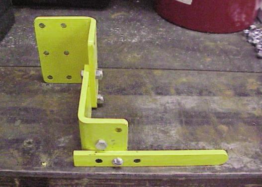

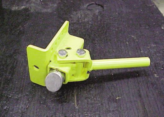
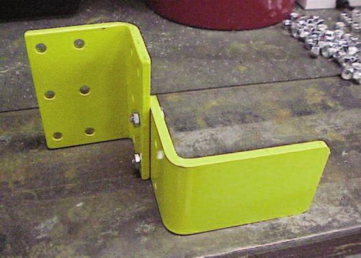

4 photos of door deputy mechanismmechanism HOLD-OPEN TM MECHANISM LOCk-DOWN TM MECHANISM CATCH BRACkET WITH FLIPPER ARM LATCH BRACkET PADDLE COVER 4 pub. no rev. 7 - July 2015


5 installation of door deputy hold-open tm mechanism tools required Flat Screwdriver Drill and Drill bits Ratchet Set Wrench 1 Drill bit, Slugbuster, Hole Saw,or equivalient warning do not install unit on powered door. the door deputy tm is designed for use on manual doors only. Figure 1 Figure 2 determine door deputy hold-open tm mechanism NOTICE mounting location Determine which side of the door the Hold-Open TM On some doors it may be necessary to add an Mechanism will be mounted on. This is done by additional track bracket to the door track near examining the area above the door opening outside the Door Deputy TM Hold-Up TM and Lock-Down TM the track. The Hold-Open TM Mechanism requires latches to limit track flexibility and movement. about 12" of space outside the track as well as 6" above and 6" below the top of the door opening. Look for control boxes, bollards, conduit, water pipes, air lines, racks, etc. that may interfere. mounting of door deputy 1. Use the hole location template, shown in Figure 1, to drill a 1" hole on the center line of the roller track 2 3 /4 above the door lintel. Drill two (2) 1 /4" holes below the center of the first hole on the center line as shown in Figure Attach the Hold-Open TM Mechanism to the track using two (2) 1 /4" X 3 /4" track bolts. Be sure to have the heads of the bolts nearest the rollers (on the inside of the track) to avoid interference during door operation. Attach one end of the rope to the lever and tie the other end to the ring supplied. Attach the ring to the wall or track to prevent the rope from blowing into the door way if desired. Move the door pull down rope to the same side as the Hold-Open TM Mechanism as well if desired. (Most customers prefer to have the Door Deputy TM and door rope on the same side). paddle attachment Attach the Paddle to the top of the Hold-Open TM Mechanism using two (2) 1 /4" X 3 /4" track bolts through the two holes of the Hold-Open TM Mechanism closest to the door. Make sure the back two holes of the paddle align with the back two holes on top of the Hold-Open TM Mechanism. Hand tighten these bolts to allow for final adjustments later in the installation. pub. no rev. 7 - July


6 mounting of door deputy tm CatCh bracket Caution work carefully to prevent injury. the springs, cables and pulleys are under tension. warning Figure 3 - Hold-Open TM Mechanism Mounting and Flap Attachment parts of this product are designed to move during operation. this movement may create pinch points. use appropriate caution when operating this equipment. Keep clear of door during operation. mounting door deputy tm Catch bracket 1. The Catch Bracket is assembled for use on the right side of the door. If the unit is to be mounted on the left side of the door, conversion will be necessary. First, unscrew the bolt that goes through the Flipper arm and move the Flipper arm to the hole which was not previously being used. Secure the bolt through the Flipper arm but do not over tighten. (See Figures 4 & 5 for completed conversions.) The Flipper arm must be able to rotate freely. For proper bracket adjustment see Adjustment Section on page 8. Figure 4- Left Side Catch Bracket 6 pub. no rev. 7 - July 2015
 1 /4\" through bolts attach the Catch Bracket on the bottom door panel just above the lowest roller on the same side of the door as the Hold-Open TM Mechanism.")
7 mounting of door deputy tm CatCh bracket Cont. 2. Using (4) 1 /4" through bolts attach the Catch Bracket on the bottom door panel just above the lowest roller on the same side of the door as the Hold-Open TM Mechanism. Be sure to align the edge of the Bracket with the edge of the door panel as shown in Figure 6. Use outer most holes if possible. warning Caution Cables will be under tension. do not completely detach cable bracket from bottom panel. door must be able to travel 3-4 above door deputy tm top lock before bumpers engage door. see bumper adjustments page 8. FiGure 6 3. Check the track to make sure there are no obstructions on or around the track that could prevent the movement of the Flipper arm which extends from the Catch Bracket as the door travels up and down. 4. In some cases, obstructions on the door may prevent the catch bracket from being mounted low enough on the door. The flipper arm half of the bracket may be lowered below the standard mounting holes, if necessary, as long as two bolts can be used to secure the bracket. Be careful not to lower the bracket below the bottom of the door. pub. no rev. 7 - July


8 installation of door deputy roller Guard 1. Secure the Roller Guard to the Catch Bracket using 2 bolts. The Roller Guard should be installed as close to the bottom of the roller as possible and engage the Lock Up Mechanism when the door is raised and the Door Deputy is activated. 2. Check to make sure the Roller Guard does not rub the track as the door is raised or lowered. Also, check to make sure the Roller Guard is passing above the plunger before the Door Deputy Hold Up Mechanism is activated. 3. Grind or cut off any part of the Roller Guard if necessary due to rubbing and touch up paint as required. The Door Deputy Flag can be bent up to delay activation if necessary. The part of the Catch Bracket attached to the Flipper Arm may also be lowered using the 2 horizontal holes to secure the bracket to delay the activation as well. roller Guard preferred mounting optional mounting Flipper arm lowered 8 pub. no rev. 7 - July 2015

9 installation of door deputy tm lock-down TM mechanism door deputy The Lock-Down TM Mechanism can be installed on either side of the door regardless of which side the Hold-Open TM Mechanism is installed. NOTE: Door Deputy Lock Down System may not work with full length Track Saver Plus. latch bracket installation Align the edge of the Latch Bracket with the edge of the door as shown in Figure 7. The Latch Bracket is normally mounted near the top of the second panel. Attach the Latch Bracket using (4) 1 /4" through bolts. It can be mounted higher if necessary due to obstructions. For proper bracket adjustment see Adjustment Section on page 8. Use outer most holes if possible. Figure 7- Latch Bracket Attachment lock-down TM mechanism installation 1. The Lock-Down TM Mechanism is assembled for use on the right side of the door. If the unit is to be mounted on the left side of the door, conversion will be necessary. To convert for left side mounting, remove the nut form the bolt that goes through the lock wedge. Be sure to hold onto the wedge as you remove the bolt to keep the wedge from being pushed out of the Lock-Down TM Mechanism. (See Figure 8) Spin the wedge one half turn (without removing the wedge from the Lock-Down TM Mechanism) and reinsert the bolt from the other side of the Lock-Down TM Mechanism. Secure the nut to complete the conversion. (See Figures 9 & 10 for completed Latch Bracket Assemblies. pub. no rev. 7 - July


10 lock-down tm mechanism installation Continued Figure 8- Lock-Down TM Mechanism Conversion Figure 9- Left Side Lock-Down TM Mechanism Figure 10- Right Side Lock-Down TM Mechanism 10 pub. no rev. 7 - July 2015

11 lock-down tm mechanism installation Continued 2. Lower the door completely. Position the Lock-Down TM Mechanism against the track just above the Latch Bracket and slide the Lock-Down TM Mechanism as close to the bracket as possible to maximize activation. Mark two holes as near the center line of the track as possible. Drill two 1 /4" holes and then install the Lock-Down TM Mechanism using the two (2) 3" X 3 /4" track bolts provided. Be sure to have the heads of the bolts nearest the rollers (on the inside of the track) to avoid interference. (See Figure 11) Figure 11 - Lock-Down TM Mechanism Mounting pub. no rev. 7 - July
12 adjustments bracket adjustments For units with both Hold-Open TM and Lock-Down TM Mechanisms set the Latch Bracket first and then the Catch Bracket. For safety reasons, it is recommended that the brackets be installed as close to the track as possible. For combination units use the same projection holes for the Latch Bracket and Catch Bracket. This will provide adequate spacing for proper operation. paddle adjustments Make sure the Latch Bracket does not activate the Hold-Open TM Mechanism. If it does adjust the position of the paddle using the alternative mounting holes. Flipper arm adjustments Once the Paddle will clear the Latch Bracket make sure the Flipper Arm fully activates the Hold- Open TM Mechanism and releases the spring by contacting the paddle. Relocate the Flipper Arm using the alternative mounting holes. top bumper adjustments Some doors have bumpers located at the top of the track to prevent the door from sliding off the top of the track. In some cases these bumpers may interfer with the proper function of the Door Deputy. DO NOT remove these bumpers, but some adjustment may be required if necessary to allow the door to go 3-4 higher up the tracks. Cover attachments After all the adjustments have been made and the unit is functioning properly the final step is to attach the cover to the Hold-Open TM Mechanism. Do this using (2) 1 /2 #10 bolts. 12 pub. no rev. 7 - July 2015
13 interlock switch pub. no rev. 7 - July

14 door deputy parts 14 pub. no rev. 7 - July 2015
15 trouble shooting problem probable Cause solution The bottom of the door hangs A. Door Deputy Hold Open is not being A. Check mounting location of Catch Bracket below top of the door opening. activated by Catch Bracket. as well as Paddle Mounting location. B. Door Deputy is activating but B1. Track bumpers that prevent the door plunger isn't below the door. from going off the top of the track are mounted too close. Carefully relocate them back further if possible. B2.Lower Catch Bracket to just above the bottom roller. C. There is a large bottom C. Mount Hold-Open TM higher. seal on this door. The Lock-Down TM Bracket A. Door Deputy TM Paddle is A. Adjust the Paddle away from the door engages the Door Deputy incorrect. opening using the adjustment hole Hold-Open TM Mechanism. provided. B. Lock-Down TM bracket is B. Move the location of the Lock-Down TM positioned incorrectly. away from the track of the door. C. Extra door thickness is C. The Paddle is made of 1/8" thick steel causing misalignment. in order that it may be cut if necessary to allow proper function. (IMPORTANT: MAkE SURE NOT TO CUT TOO MUCH OF THE PADDLE OFF MAkING THE HOLD- OPEN TM MECHANISM FUNCTIONLESS. Door can become unlocked A. Bracket positioning. A. Relocate Lock-Down TM bracket by moving by pulling door away from it towards the track.(important:over the Lock-Down TM. ADJUSTMENT CAN CAUSE EXCESSIVE WEAR TO THE TRACk AND/OR THE BRACkET AS WELL AS CAUSE EARLY HOLD-OPEN TM MECHANISM ACTIVATION. B. Lock-Down TM Mechanism B. Move the Lock-Down TM away from the isn't mounted far enough using the alternative mounting holes away from the track. provided. The Lock-Down TM Bracket A. The Lock-Down TM Bracket A. Place washers or spacers between the catches on the door track as doesn't project far enough door and both brackets. Place an the door is raised or lowered. away from the door. equal number of spacers so the interaction between the floor Deputy parts is not affected. Top Latch will not deactivate. A. The Hold-Open TM Mechanism A. Pull the rope until the paddle rises and falls not being fully activated by again signifying it's engagement with the the user. plunger. B. The door is caught between B. Raise or lower the door enough that the Hold-Open TM Mechanism cycles. Paddle can lower and then pull on the rope until the paddle rises and falls unlocking the plunger. C. The pull rope is not routed C. Re-route the rope through the Hold-Open TM correctly through the Hold- Mechanism as shown in the instructions. Open TM Mechanism. pub. no rev. 7 - July
16 rite-hite warranty RITE-HITE warrants that its door deputy, will be free from defects in design, materials and workmanship for a period of one (1) year parts and one (1) year labor from the date of shipment. All claims for breach of this warranty must be made within thirty (30) days after the defect is or can, with reasonable care, be discovered to be entitled to the benefits of this warranty, the products must have been properly installed, maintained, operated within their rated capacities, and not otherwise abused. Periodic lubrication and adjustment is the sole responsibility of the owner. This warranty is RITE-HITE exclusive warranty. RITE-HITE EXPRESSLY DISCLAIMS ALL IMPLIED WARRANTIES INCLUDING THE IMPLIED WARRANTIES OF MERCHANTABILITY AND FITNESS. Nonstandard RITE-HITE warranties, if any, must be specified by RITE-HITE in writing. In the event of any defects covered by this warranty, RITE-HITE will remedy such defects by repairing or replacing any defective equipment or parts, bearing all of the costs for parts, labor, and transportation. This shall be the exclusive remedy for all claims whether based on contract negligence or strict liability. Neither RITE-HITE, ANY OTHER MANUFACTURER WHOSE PRODUCTS ARE THE SUBJECT OF THIS TRANSACTION, NOR ANY RITE-HITE REPRESENTATIVE, SHALL IN ANY EVENT BE LIABLE FOR ANY LOSS OR USE OF ANY EQUIPMENT OR INCIDENTAL OR CONSEQUENTIAL DAMAGES OF ANY kind WHETHER FOR BREACH OF WARRANTY, NEGLIGENCE, OR STRICT LIABILITY. The application of a manufacturer's specifications to a particular job is the responsibility of the purchaser. RITE-HITE SHALL NOT IN ANY EVENT BE LIABLE FOR ANY LOSS OF THE USE OF ANY EQUIPMENT OR INCIDENTAL OR CONSEQUENTIAL DAMAGES OF ANY kind. a F t e r m a r K e t C o r p o r at i o n 8900 n. arbon drive p.o. box milwaukee, wisconsin sales: toll Free: representatives in all major Cities to find the name and number of your local rite-hite representative please visit 16 pub. no rev. 7 - July 2015
RITE-HITE VHLS. Vertical Under-Leveler Seal Installation Instructions & Owner s Manual. Date of Installation:
 RITE-HITE VHLS Vertical Under-Leveler Seal Installation Instructions & Owner s Manual Date of Installation: This Manual Covers All Units Shipped 4/2014 to Date PRINTED IN U.S.A. PUBLICATION VHLS0003 REV.
VBR-600 Dok-Lok Vehicle Restraint Installation Manual
 VBR-600 Dok-Lok Vehicle Restraint Installation Manual MADE IN U.S.A. This Manual Covers Restraints Built After Serial Numbers: VB6001000 and up PRINTED IN U.S.A. RITE-HITE PRINT SHOP PUBLICATION NO. 1327
FLEETWOOD TRAVEL TRAILER SLIDEOUT SYSTEM OWNER S MANUAL
 FLEETWOOD TRAVEL TRAILER SLIDEOUT SYSTEM OWNER S MANUAL 82-S0150-01 REV. 1 April, 2002 TABLE OF CONTENTS PAGE # OPERATIONS MANUAL... 1 1. SYSTEM DESCRIPTION... 1 1.1 MAJOR COMPONENTS... 1 2. HOW TO OPERATE
Amarr SuperFlex. Installation Instructions and Owner's Manual. Entrematic 165 Carriage Court Winston Salem, NC
 Entrematic 165 Carriage Court Winston Salem, NC 27105 www.amarr.com 877-512-6277 Amarr SuperFlex Installation Instructions and Owner's Manual Do not install, operate or service this product unless you
HATCHGRIP Installation Instructions/Operation and Maintenance Manual
 HATCHGRIP Installation Instructions/Operation and Maintenance Manual Models: HTG-PCG Contact Information Table of Contents: Safety Precautions... 2 Product Information... 2 Operation... 3 Installation
Mega-Flow External Damper Fans
 Mega-Flow External Damper Fans With Cone Owner s Manual Hired-Hand, Mfg., Inc. PO Box 140 1733 County Road 68 Bremen, Alabama 35033 Part No. 4801-5402 Rev 4/08 Owners Manual Mega-Flow External Damper Fans
CRD610 Automatic Fitting Inserter
 CRD610 Automatic Fitting Inserter OPERATIONS MANUAL VERSION 1.2 LAST EDITED 12.12.2018 cleanroomdevices.com 1 Table of Contents Title Page. 1 Table of Contents...2 1.0 General Product & Safety Information....3
POWER GEAR SLIDE-OUT MANUAL
 POWER GEAR SLIDE-OUT MANUAL Operation Guide FLUSH FLOOR SLIDE-OUT SYSTEM FOR AMERICAN COACH PRODUCTS 82-S0220-01 Rev. 1 AMERICAN COACH SLIDE-OUT MANUAL FLUSH FLOOR SYSTEM TABLE OF CONTENTS SECTION PAGE
Installation Instructions and Service Manual
 Installation Instructions and Service Manual Model 80 Actuator* for Trailer Brakes 8,00 lbs Capacity Drum Brake Ready Disc Brake Ready US Patents: 6,37,2 and 8,342,9 *Model 80 - Manufactured after March
Installation Instructions
 85-4592 rev. 08 02-18 Installation Instructions Thank you for purchasing our sway bar kit. Please read through these instructions before installation. Auxiliary Rear Anti-Sway Bar Kit for Ford F53 part
CRD600 Automatic Fitting Inserter
 CRD600 Automatic Fitting Inserter OPERATIONS MANUAL VERSION 2.3 LAST EDITED 12.07.2018 cleanroomdevices.com 1 Table of Contents Title Page.. 1 Table of Contents. 2 1.0 General Product & Safety Information...3
Installation & Operators Manual
 Installation & Operators Manual Model Serial Number Purchase Date 2007-2008 SegVator, LLC Patent Pending All Rights Reserved Important Safety Information Make sure the vehicle has a properly installed
REDI-LINE. Rugged, Reliable, DC to AC Power Conversion ELECTRIC GENERATORS USER'S GUIDE. KARAM A.L.
 REDI-LINE ELECTRIC GENERATORS USER'S GUIDE Rugged, Reliable, DC to AC Power Conversion KARAM A.L. www.alternatorstarter.com 1-888-515-2726 REDI-LINE ELECTRIC GENERATOR MODEL INPUT ACTUAL OUTPUT ACTUAL
1016 SERIES INSTALLATION, OPERATION, MAINTENANCE & PARTS
 LIMITED WARRANTY CHEVRON, INC., ("Chevron"), warrants to the original purchaser that each new Chevron product will be free from defects in material and workmanship for a period of twelve (12) months from
Vehicle Restraint Installation Manual
 Vehicle Restraint Installation Manual 2017 Nova Technology International, LLC Manual No. MF2-093-000 - June 2017 TABLE OF CONTENTS SAFETY WARNINGS................. WARRANTY..... 3 7 21 Manual No. MF2-093-000
CLEAN ROOM DEVICES, LLC "WHERE TUBING AND FITTINGS COME TOGETHER"
 CLEAN ROOM DEVICES, LLC "WHERE TUBING AND FITTINGS COME TOGETHER" CRD600AF Automatic Fitting Inserter With Auto Feed OPERATIONS MANUAL (Shown with optional alcohol dispenser) 1 VERSION 1.1 LAST EDITED
INSTALLATION MANUAL FAST RACK LADDER SYSTEM
 TRUCK STORAGE SOLUTIONS SECURING YOUR REPUTATION INSTALLATION MANUAL FAST RACK LADDER SYSTEM MODELS ATTENTION: PLEASE READ AND UNDERSTAND ALL INSTRUCTIONS AND WARNINGS BEFORE ASSEMBLING, INSTALLING OR
A S S E M B L Y I N S T R U C T I O N S
 A S S E M B L Y I N S T R U C T I O N S Please Do Not Return This Product to the Store! Contact Escalade Sports customer service department at: Phone: 1-888-USA-GOAL Toll-Free! Fax: 1-866-873-3536 Toll-Free!
MODEL V-24 OWNER'S MANUAL PARTS
 OWNER'S MANUAL MODEL V-24 PARTS NOTE: MANUAL including SPECIFICATIONS, subject to change without notice All ratings specified are based on structural factors only, not vehicle capacities or capabilities.
OWNER'S MANUAL. Please Do Not Return This Product To The Store!
 TABLE TENNIS TABLE MODEL NO. T87 OWNER'S MANUAL 1. Read this manual carefully before starting assembly. Read each step completely before beginning each step. 2. Some smaller parts may be shipped inside
TAILGATE SPREADER INSTALLATION & OWNER S MANUAL TABLE OF CONTENTS
 A Division of Northern Star Industries, Inc. P.O. Box 788 Iron Mountain MI 49801-0788 www.bossplow.com SMARTHITCH 1100 TAILGATE SPREADER INSTALLATION & OWNER S MANUAL TABLE OF CONTENTS S & CAUTIONS...
The Ultimate Smart Grid Solution INSTRUCTION MANUAL
 ECOWISE EW30/1 The Ultimate Smart Grid Solution INSTRUCTION MANUAL Welcome! Congratulations on selecting the ECOWISE unit to manage your energy supply needs. ECOWISE units reduce the amount of electric
CLEAN ROOM DEVICES, LLC "WHERE TUBING AND FITTINGS COME TOGETHER"
 CLEAN ROOM DEVICES, LLC "WHERE TUBING AND FITTINGS COME TOGETHER" CRD600 Automatic Fitting Inserter OPERATIONS MANUAL VERSION 2.1 LAST EDITED 7.25.14 DOCUMENT NUMBER 001 cleanroomdevices.com 1 Table of
14", 18" & 24" Fiberglass Turbo Fans Installation & Operator s Instruction Manual
 14", 18" & 24" Fiberglass Turbo Fans Installation & Operator s Instruction Manual 09484:09#52
BMK-30. Heavy-Duty By-Pass Filtration System Installation and Servicing Instructions
 BMK-30 Heavy-Duty By-Pass Filtration System Installation and Servicing Instructions IMPORTANT NOTICE Read all instructions completely before attempting to install this unit. Improper installation could
JD 900F TILT SENSOR INSTALLATION
 JD 900F TILT SENSOR INSTALLATION Conversion Manual 09040108b HEADSIGHT.COM 574.546.5022 About Headsight Headsight Contact Info Headsight, Inc. 4845 3B Road Bremen, IN 46506 Phone: 574-546-5022 Fax: 574-546-5760
HR-20P Pneumatically Controlled Pressure Regulator
 HR-20P Pneumatically Controlled Pressure Regulator Instruction and Service Manual Hydroplex Corporation 230 West Gloria Switch Rd. Lafayette, LA 70507 337-233-0626 www.hydroplexpumps.com I. General Instructions
The Ultimate Smart Grid Solution INSTRUCTION MANUAL
 ECOWISE EW20/1 EW30/1 The Ultimate Smart Grid Solution INSTRUCTION MANUAL Welcome! Congratulations on selecting the ECOWISE unit to manage your energy supply needs. ECOWISE units reduce the amount of electric
Read this entire manual before operation begins.
 Read this entire manual before operation begins. Record below the following information which is located on the serial number data plate. Serial No. Model No. Date of Installation Contents Specifications.............
PxV INSTALLATION GUIDE Models DR0880-TB thru DR0888-TB Tiltback Doors (Torsion Spring)
") PxV INSTALLATION GUIDE Models DR0880-TB thru DR0888-TB Tiltback Doors (Torsion Spring) 340 Gateway Park Drive North Syracuse, NY 13212 Phone: 315-463-7348 Toll Free: 866-235-7468 Fax: 315-463-8559 Email:
PxV INSTALLATION GUIDE Models DR0880-TB thru DR0888-TB Tiltback Doors (Torsion Spring) 340 Gateway Park Drive North Syracuse, NY 13212 Phone: 315-463-7348 Toll Free: 866-235-7468 Fax: 315-463-8559 Email:
Thatching Reel Reelmaster 450 D, 4500 D, 335 D & 3500 D
 Form No. 3350 8 Thatching Reel Reelmaster 450 D, 4500 D, 335 D & 3500 D Model No. 0373 Serial No. 5000000 and Up Model No. 03730 Serial No. 5000000 and Up Operator s Manual English (EN) Introduction Read
Model 66/660* Actuator for Trailer Brakes 6,600 lbs Capacity Drum Brake Ready or Disc Brake Ready US Patent No. 6,375,211
 Installation Instructions and Service Manual Model 66/660* Actuator for Trailer Brakes 6,600 lbs Capacity Drum Brake Ready or Disc Brake Ready US Patent No. 6,375,211 *Model 660 - Manufactured after March
Pneumatic Cylinder 14 Bore X 22 Stroke Part No. R (Formerly P )
") Pneumatic Cylinder 14 Bore X 22 Stroke Part No. R434001268 (Formerly P -193419-00003) Service Information INSTALLATION Before installing this cylinder, all air lines in the system should be blown clean
Pneumatic Cylinder 14 Bore X 22 Stroke Part No. R434001268 (Formerly P -193419-00003) Service Information INSTALLATION Before installing this cylinder, all air lines in the system should be blown clean
Part Number Mini Linear Lift Assembly Installation & Operator s Instruction Manual
 Part Number 39644 Mini Linear Lift Assembly Installation & Operator s Instruction Manual April 1999 MV1505C Chore-Time Warranty Mini Linear Lift Assembly Manual Chore-Time Warranty Chore-Time Equipment
Installation Procedures Dodge Challenger Hellcat (Upper Mount) SNS 1e
 SNS 1e") Installation Procedures 2015-16 Dodge Challenger Hellcat (Upper Mount) SNS 1e Warning: Please read directions completely before starting. If you have any questions, please contact BMPP before beginning
Installation Procedures 2015-16 Dodge Challenger Hellcat (Upper Mount) SNS 1e Warning: Please read directions completely before starting. If you have any questions, please contact BMPP before beginning
Instruction Sheet SRSR SERIES. Rotating Sliding Rail System
 Instruction Sheet SRSR SERIES Rotating Sliding Rail System THANK YOU Thank you for purchasing the SRSR Series Rotating Sliding Rail System. Please read these instructions thoroughly before assembling this
RollSeal 1733 County Road 68 Bremen, Alabama Part No Rev Owner s Manual RS-Divider Curtain
 1. 2. 7 3. 4. RollSeal 1733 County Road 68 Bremen, Alabama 35033 256-287-7000 Part No 4801-5176 Rev 12-11-17 Owner s Manual RS-Divider Curtain Table of Contents 1 Warnings (Avertissements)... 3 2 Limited
OnBoard Drum Major Podium
 Assembly and Owner s Manual OnBoard Drum Major Podium CONTENTS CONTENTS................................................................................. 1 SAFETY...................................................................................
Full Length Bed Rail - Model G29
 User Manual DEALER: These instructions MUST be given to the user of the product. USER: BEFORE using this product, read this manual and save for future reference. 1 General Check all parts for shipping
Lubricator Gun: 10,000 psi (700 bar) Maximum Delivery Pressure when disconnected from Dispenser
 Maximum Delivery Pressure when disconnected from Dispenser") INSTRUCTIONS-PARTS LIST 30 455 INSTRUCTIONS This manual contains important warnings and information. READ AND KEEP FOR REFERENCE. Rev. C Supercedes B Hand-Operated Portable Grease Dispenser Buckshot Luber
INSTRUCTIONS-PARTS LIST 30 455 INSTRUCTIONS This manual contains important warnings and information. READ AND KEEP FOR REFERENCE. Rev. C Supercedes B Hand-Operated Portable Grease Dispenser Buckshot Luber
Installation Procedures Ford F150 Lightning SVT SNS 60
 Installation Procedures 1993-2003 Ford F150 Lightning SVT SNS 60 Warning: Please read directions completely before starting. If you have any questions please contact BMPP before beginning your installation.
OPERATOR S AND PARTS MANUAL PALLET FORKS. Part Number: MODEL NUMBER: Rev. 4
 OPERATOR S AND PARTS MANUAL PALLET FORKS SERIAL NUMBER: Manual Number: OM642 Part Number: 75542 MODEL NUMBER: Rev. 4 800-456-7100 I www.paladinlcg.com 503 Gay Street, Delhi, IA 52223, United States of
Pneumatic Cylinder 14 Bore X 21 Stroke Part No. P Replaces Part No. P
 Pneumatic Cylinder 14 Bore X 21 Stroke Part No. P -322908-00000 Replaces Part No. P-191067-00000 Service Information WARNING: INSTALLATION AND MOUNTING The user of these devices must conform to all applicable
HF4145 FOLDING MULTI-POSITION WORKOUT BENCH
 HF4145 FOLDING MULTI-POSITION WORKOUT BENCH Note: Both Serial Number and Model Number are Required when Ordering Parts RECORD SERIAL NUMBER HERE CATALOG NUMBER 0406-001 Customer Service (800) 548-5438
Instruction Manual For Baldor Buffers
 No. 280F Replaces 280E LB7011 Instruction Manual For Baldor Buffers SAFETY NOTICE: WARNING statements describe conditions that may lead to personnel injury including potentially fatal injuries if the machine
Veterinary Anesthesia Gas Scavenging System (Active)
") Veterinary Anesthesia Gas Scavenging System (Active) Installation and Operation Manual MX103200i 10434800 Rev. AA1 5/5/17 Table of Contents Section 1 UNPACKING...2 1.1 Examining Packaged Components...2
Veterinary Anesthesia Gas Scavenging System (Active) Installation and Operation Manual MX103200i 10434800 Rev. AA1 5/5/17 Table of Contents Section 1 UNPACKING...2 1.1 Examining Packaged Components...2
5 th Airborne Sidewinder Service Kit Instructions 94316
 94316 Equipment Required: Wrenches: 15/16, Torque Wrench, Rubber Mallet 3 4 5 2 Included Service Kit Items: 1 Qty. (1) Wear Plate 2 Qty. (1) Wear Bushing 3 Qty. (1) Wear Disc 4 Qty. (4) 5/8-11x2 GRD8 Bolt
Installation Instructions
 85-3847 rev. 01 09-09 Installation Instructions Thank you for purchasing this anti-sway bar kit. Please read through these instructions before installation. Front Anti-Sway Bar TruTrac Bar Combo Kit for
Air Curtain. Installation, Operating and Maintenance Instructions
 Installation, Operating and Maintenance Instructions Save this manual for future reference. Air Curtain Model Numbers: ES026, ES036, ES042, ES048, ES060, ES072 READ THIS OWNER S MANUAL CAREFULLY BEFORE
LUBRICATOR GUN INSTRUCTIONS-PARTS LIST. 10,000 psi (700 bar) Maximum Delivery Pressure. Detachable-type
 Maximum Delivery Pressure. Detachable-type") INSTRUCTIONS-PARTS LIST 306 460 INSTRUCTIONS This manual contains important warnings and information. READ AND KEEP FOR REFERENCE. Rev. E Supercedes D Detachable-type LUBRICATOR GUN 10,000 psi (700 bar)
INSTRUCTIONS-PARTS LIST 306 460 INSTRUCTIONS This manual contains important warnings and information. READ AND KEEP FOR REFERENCE. Rev. E Supercedes D Detachable-type LUBRICATOR GUN 10,000 psi (700 bar)
DRAGO. Corn Header Manual f HEADSIGHT.COM
 DRAGO Corn Header Manual 09020801f HEADSIGHT.COM 574.546.5022 About Headsight Headsight Contact Info Headsight, Inc. 4845 3B Road Bremen, IN 46506 Phone: 574-546-5022 Fax: 574-546-5760 Email: info@headsight.com
LEV/Wn Building A Connected World
 LEV/Wn Building A Connected World PK-93370-10-00-2B Installing and Testing a GFCI Please read this leaflet completely before getting started. A CAUTION To prevent severe shock or electrocution always turn
Installation Instructions
 85-4209 rev. 05 11-18 Installation Instructions Thank you for purchasing this anti-sway bar kit. Please read through these instructions before installation. Factory Replacement Anti-Sway Bar Kit part #1129-135
HQZ & RBM MODEL LIFT & TRANSFERS
 Technical Documentation HQZ & RBM MODEL LIFT & TRANSFERS Each serial number is unique to that specific conveyor and provides mk North America with complete order details. The conveyor serial number is
Vehicle Restraint Owner s Manual
 Vehicle Restraint Owner s Manual RHR-4000 9 Carriage RHR-4000 12 Carriage MADE IN U.S.A. This Manual Covers Restraints Built After Serial Numbers: RHR001000 and up PRINTED IN U.S.A. RITE-HITE PRINT SHOP
Model 80 & 80E Actuator* for Trailer Brakes 8000 lbs Capacity Part #47206/ Drum Brake Ready Part #47208/ Disc Brake Ready
 Installation Instructions and Service Manual For Serial Numbers 6020 and above. Model 80 & 80E Actuator* for Trailer Brakes 8000 lbs Capacity Part #47206/47207 - Drum Brake Ready Part #47208/47209 - Disc
SP-850 INSTALLATION, OPERATION, MAINTENANCE & PARTS
 OWNER'S MANUAL SP-850 INSTALLATION, OPERATION, MAINTENANCE & PARTS NOTE: MANUAL including SPECIFICATIONS, subject to change without notice All ratings specified are based on structural factors only, not
DWS404 DWS524 DWS654 DWS684 DWS694. DWS SERIES INSTALLATION/OWNER'S MANUAL Car Audio Speakers
 DWS404 DWS524 DWS654 DWS684 DWS694 DWS SERIES INSTALLATION/OWNER'S MANUAL Car Audio Speakers PREPARATION Safety Guidelines Thank you for purchasing the DWS Series car speakers. Although Dual has attempted
Premium Series Grease Dispensing Handle One and Two Piece Body Styles
 Service Bulletin SB3018 Rev. A 3/07 Premium Series Grease Dispensing Handle One and Two Piece Body Styles Models: Handle w/swivel and 36" Whip Hose 020 Handle w/swivel and 18" Whip Hose 025 Handle w/swivel
SHAW-BOX INSTRUCTIONS AND PARTS LIST SHAW-BOX RIGID MOUNT I-BEAM AND PATENTED TRACK TROLLEYS (PUSH & HAND GEARED - 1/2 THRU 15 TON RATED LOADS)
") SHAW-BOX INSTRUCTIONS AND PARTS LIST SHAW-BOX RIGID MOUNT I-BEAM AND PATENTED TRACK TROLLEYS (PUSH & HAND GEARED - 1/2 THRU 15 TON RATED LOADS) GENERAL SHAW-BOX Rigid Mount I-Beam Trolleys are designed
SHAW-BOX INSTRUCTIONS AND PARTS LIST SHAW-BOX RIGID MOUNT I-BEAM AND PATENTED TRACK TROLLEYS (PUSH & HAND GEARED - 1/2 THRU 15 TON RATED LOADS) GENERAL SHAW-BOX Rigid Mount I-Beam Trolleys are designed
Assembly, Installation, Operation and Maintenance Instructions. Base Rail Bracket Kit. For updates see PRODUCT SUPPORT tab at
 Assembly, Installation, Operation and Maintenance Instructions P/N: 31408 Base Rail Bracket Kit For updates see PRODUCT SUPPORT tab at www.huskytow.com Provide a copy of these Instructions to the end user
GERINGHOFF. Corn Header Manual f HEADSIGHT.COM
 GERINGHOFF Corn Header Manual 09020701f HEADSIGHT.COM 574.546.5022 About Headsight Headsight Contact Info Headsight, Inc. 4845 3B Road Bremen, IN 46506 Phone: 574-546-5022 Fax: 574-546-5760 Email: info@headsight.com
Installation Instructions
 85-3909 rev. 01 09-09 Installation Instructions Thank you for purchasing this anti-sway bar kit. Please read through these instructions before installation. Rear Anti-Sway Bar Kit for Chevrolet G30 part
Air and water reels. Models and Series B. Installation and maintenance guide DANGER
 Installation and maintenance guide Air and water reels Models 83753 and 83754 Series B Date of issue June 2014 Form number 404665A Section E35 Page 83A DANGER Read manual prior to installation or use of
ZRF-P 2040 TIMING BELT CONVEYOR
 Technical Documentation ZRF-P 2040 TIMING BELT CONVEYOR Each serial number is unique to that specific conveyor and provides mk North America with complete order details. The conveyor serial number is located
INSTALLATION INSTRUCTIONS QA1 P/N R , R , R R , R , R F100 Rear Coil-over Conversion System
 INSTALLATION INSTRUCTIONS QA1 P/N R120-170, R120-200, R120-250 R220-170, R220-200, R220-250 65-72 F100 Rear Coil-over Conversion System TOOLS AND SUPPLIES REQUIRED Floor Jack Two (2) Jack Stands Drill
Please Do Not Return This Product To The Store!
 TABLE TENNIS TABLE MODEL NOS. T8167 QUICKPLAY 1000 T8267 QUICKPLAY 1000 T8180 METRO OWNER'S MANUAL 1. Read this manual carefully before starting assembly. Read each step completely before beginning each
Installation Power Management Unit Battery Cables and Battery Harness
 Installation Power Management Unit Battery Cables and Battery Harness Important Safety Messages SAVE THESE INSTRUCTIONS - This manual contains important instructions that should be followed during installation
GLOBAL WHEEL-LOK. GWL-2100 Vehicle Restraint
 GLOBAL WHEEL-LOK GWL-2100 Vehicle Restraint Versatility Safely restrains virtually all trailer types including trailers without effective rear impact guards. Maximize uptime Simple, electro-mechanical
WIRING DIAGRAMS FOR BRIDGE CONTROL PANELS
 WIRING DIAGRAMS FOR BRIDGE CONTROL PANELS Bridge W/D's Panel Part # Page No. Nema-4/12 1-Speed 444231-** 2 Nema-4/12 1-Speed with Soft-Start 444711-** 3 Nema-4/12 2-Speed 444232-** 4 Nema-4/12 2-Speed
2SHE Series Direct-Drive Shutter Fans
 Operational Instruction and Parts Manual Item #: 481810 Rev Date: 101414 2SHE Series Direct-Drive Shutter Fans Fantech, Inc. and Systemair Mfg. certify that the ventilators shown herein are licensed to
INSTALLATION/OWNER'S MANUAL DP " Woofer in Enclosure
 INSTALLATION/OWNER'S MANUAL DP1000 10" Woofer in Enclosure Installation Thank you for purchasing the DP1000 10" Woofer with enclosure. Although Dual has attempted to make sure all of the information contained
MxV INSTALLATION GUIDE MxV Torsion Spring High Lift Door Models DR0810-TS-3 thru DR0818-TS-3
 MxV INSTALLATION GUIDE MxV Torsion Spring High Lift Door Models DR0810-TS-3 thru DR0818-TS-3 340 Gateway Park Drive North Syracuse, NY 13212 Phone: 315-463-7348 Toll Free: 866-235-7468 Fax: 315-463-8559
1014 SERIES INSTALLATION, OPERATION, MAINTENANCE & PARTS
 OWNER'S MANUAL 1014 SERIES INSTALLATION, OPERATION, MAINTENANCE & PARTS NOTE: MANUAL including SPECIFICATIONS, subject to change without notice. All ratings specified are based on structural factors only,
16K and 19K Sidewinder TM Service Kit Instructions 86005
 86005 Equipment Required: Wrenches: 15/16, 1 1/8, Torque Wrench, Rubber Mallet Included Service Kit Items: 1 Qty. (1) Wear Plate 2 Qty. (6) 5/8 Conical Washer 3 Qty. (2) Wedge Bolt, 5/8-11 X 1 3/4 GRD
Installation Procedures Ford F150 2X4, 4X4, Flex Fuel & Eco boost SNS 42
 Installation Procedures 2009-2014 Ford F150 2X4, 4X4, Flex Fuel & Eco boost SNS 42 Warning: Please read directions completely before starting. If you have any questions please contact BMPP before beginning
Power Float Manifold. Installation and Operations Manual Module 11A
 Power Float Manifold Installation and Operations Manual Module 11A 2/14 Table of Contents 1 Features 3 2 Functional Purpose 3 3 4 Specifications System Installation 3 4 4.1 Hydraulic Connection 4 4.2 Electric
SERIES 30 INSTALLATION, OPERATION, MAINTENANCE & PARTS
 OWNER'S MANUAL SERIES 30 INSTALLATION, OPERATION, MAINTENANCE & PARTS NOTE: MANUAL including SPECIFICATIONS, subject to change without notice. All ratings specified are based on structural factors only,
INSTALLATION INSTRUCTIONS
 REV 3 05/13/2016 PART NO. 911000T 911000PS 915000T 915000PS PRODUCT DESCRIPTION: Sport Bar 2.0, Full size Textured Black Sport Bar 2.0, Full size Polished Stainless Steel Tubes Sport Bar 2.0, Mid size
INSTRUCTIONS PARTS LIST This manual contains important warnings and information. READ AND RETAIN FOR REFERENCE
 INSTRUCTIONS PARTS LIST 308 493 This manual contains important warnings and information. READ AND RETAIN FOR REFERENCE Rev. A Second Gun Hose Kit 100 psi (6.9 bar) Maximum Working Pressure These kits include
1250 LB. CAPACITY MECHANICAL WHEEL DOLLY
 1250 LB. CAPACITY MECHANICAL WHEEL DOLLY 67287 SET-UP AND OPERATING INSTRUCTIONS Visit our website at: http://www.harborfreight.com Read this material before using this product. Failure to do so can result
Model 90 Twin Control Unit
 Model 90 Twin Control Unit Installation Manual MAY 02 Model 90 Twin Control Unit Installation Manual Page 1 MA1277B Warranty Information Chore-Time Equipment, a division of CTB, Inc., ("Chore-Time") warrants
Premium Supply. Tilt Deck. Models PCK-TD PCK-PTD. Operator s Manual and Installation Instructions
 Tilt Deck Models PCK-TD PCK-PTD Operator s Manual and Installation Instructions Premium Supply 2038 West Interstate 30 866-934-0777 Proud members of: and June 1, 2015 Table of Contents Introduction...
OPERATIONS MANUAL LEVER CHAIN HOIST
 OPERATIONS MANUAL LEVER CHAIN HOIST IMPORTANT SAFETY INFORMATION Please read, understand and follow all safety information contained in these instructions prior to the use of this hoist. Retain these instructions
TS69 TS65 TS55 TS45 TS5768 TS SERIES INSTALLATION/OWNER'S MANUAL
 TS69 TS65 TS55 TS45 TS5768 TS SERIES INSTALLATION/OWNER'S MANUAL Car Audio Speakers TS SERIES PREPARATION Getting Started Thank you for purchasing the TS Series car speakers. Although Dual has attempted
Fifth Wheel Power Hitch Operations Manual
 Fifth Wheel Power Hitch Operations Manual ITD1253 Fifth Wheel Power Hitch 208 587 7960 www.intheditch.com This page is intentionally left blank. Operations Manual 1 TABLE OF CONTENTS TABLE OF CONTENTS...
Installation Instructions
 85-3214 rev. 07 03-11 Installation Instructions Thank you for purchasing this anti-sway bar kit. Please read through these instructions before installation. Rear Anti-Sway Bar Kit Freightliner FL Series
Service Guide JATCO Environmental Protection Tank Model J-7000
 Service Guide JATCO Environmental Protection Tank Model J-7000 Listed below are a series of steps to follow if the JATCO tank fails to dump properly. #1. Be sure there is an adequate supply of gas pressure
DM1016S INSTALLATION/OWNER'S MANUAL 10" Marine DVC Subwoofer
 DM1016S INSTALLATION/OWNER'S MANUAL 10" Marine DVC Subwoofer DM1016S INSTALLATION Preparation/Installation Please read entire manual before installation. Before You Start Disconnect negative battery terminal.
COOPER POWER SERIES. S.T.A.R. type LVR faulted circuit indicator installation instructions. Fault Indicators MN320005EN
 Fault Indicators MN320005EN Effective March 2017 Supersedes December 2008 (S320-50-1) COOPER POWER SERIES S.T.A.R. type LVR faulted circuit indicator installation instructions DISCLAIMER OF WARRANTIES
Installation Instructions
 85-4341 rev. 04 10-15 Installation Instructions Thank you for purchasing this antisway bar kit. Please read through these instructions before installation. Rear Anti-Sway Bar Kit for Chevy 2500/3500/4500
AGCO. Corn Header Manual d HEADSIGHT.COM
 AGCO Corn Header Manual 09020401d HEADSIGHT.COM 574.546.5022 About Headsight Headsight Contact Info Headsight, Inc. 4845 3B Road Bremen, IN 46506 Phone: 574-546-5022 Fax: 574-546-5760 Email: info@headsight.com
UNIVERSAL CUSTOMIZABLE MUD FLAP INSTALLATION INSTRUCTIONS
 UNIVERSAL CUSTOMIZABLE MUD FLAP INSTALLATION INSTRUCTIONS Thank you for purchasing ROCKSTARTM Splash Guard Mud Flaps. Agri-Cover, Inc. proudly manufactured these mud flaps using superior quality materials
Installation Instructions
 85-5029 rev. 03 06-17 Installation Instructions Thank you for purchasing our anti-sway bar kit. Please read through these instructions before installation. Rear Anti-Sway Bar Kit for Workhorse W22, Holiday
COOPER POWER SERIES. Mercury switch to microswitch retrofit kit KA349WE installation instructions. Reclosers MN280022EN
 Reclosers MN280022EN Effective October 2015 Supersedes S280-40-10 April 2014 COOPER POWER SERIES Mercury switch to microswitch retrofit kit KA349WE installation instructions DISCLAIMER OF WARRANTIES AND
GETZ EQUIPMENT INNOVATORS PART NO.: 3G59419 MODEL: BV 101 P PNEUMATIC BELT VISE WITH EXTENDED BELT & ROLLER
 GETZ EQUIPMENT INNOVATORS PART NO.: 3G59419 MODEL: BV 101 P PNEUMATIC BELT VISE WITH EXTENDED BELT & ROLLER 2320 Lakecrest Drive, Pekin IL 61554 PH. (888) 747-4389 Fax (309) 495-0625 Website: www.getzequipment.com
EASY CONNECT CRANE KIT Festoon Conductor Systems
 ASSEMBLY INSTRUCTION MANUAL EASY CONNECT CRANE KIT Festoon Conductor Systems October, 2005 Copyright 2005, Yale Lift-Tech, division of Columbus McKinnon Corporation Part No. 117463-05 Mounting Instructions
Linear Actuator. Installation Manual. warranty installation parts list. Linear Actuator Installation Manual Page 1
 Linear Actuator Installation Manual warranty installation parts list January 2004 Linear Actuator Installation Manual Page 1 MA1221B12 Warranty Information Chore-Time Equipment ( Chore-Time ) warrants
MG12K24T60V4 Mechanical Grapple
 170 State Route 271 Attachment Solutions MG12K24T60V4 Mechanical Grapple Operators Manual KENCO Mechanical Grapple Operation Manual 1 TABLE OF CONTENTS 170 State Route 271 Section I. General Information....
AXS609 AXS612 AXS514 AXS SERIES. INSTALLATION/OWNER'S MANUAL Car Audio
 AXS609 AXS612 AXS514 AXS SERIES INSTALLATION/OWNER'S MANUAL Car Audio PREPARATION Safety Guidelines Thank you for purchasing the AXS Series car speakers. Although Axxera has attempted to make sure all