Section Description Page
|
|
|
- Darrell Russell
- 6 years ago
- Views:
Transcription
1
2 Table of contents IOM part number: Rev. A Section Description Page 1.0 INTRODUCTION Description How it works INSTALLATION Preparation Mounting Actuating Supply Systems OPERATION Conditions of Operation Pressure, Speed, and Temperature Limits Wear in Procedure Periodic Inspection MAINTENANCE Periodic maintenance Wear Limits Friction Shoe Assembly Inspection & Replacement Seal Replacement Piston Replacement ACCESSORIES Pressure Intensifiers Air over Hydraulics ORDERING INFORMATION/TECHNICAL ASSISTANCE Equipment Reference PARTS Basic Assemblies KITS Seal Kit Piston Replacement Kit Friction Shoe Assemblies REVISION PAGE 15 2 EATON CA DP100 Caliper Disc Brake Assembly Installation, Operation and Maintenance Manual E-CLCL-TT003-E August 2015
3 Index of tables Table No. Table Title Page 1 Item Description 4 2 Fastener Description and Assembly Torque - ft.-lb. (Nm) 7 EATON CA DP100 Caliper Disc Brake Assembly Installation, Operation and Maintenance Manual E-CLCL-TT003-E August
4 Bleed screw Figure 1 Figure Figure 3 Table 1 Item Description Item Description 1 Pin 2 Sleeve 3 Spring Guide 4 Washer 5 Friction Shoe Retainer 7 Friction Shoe Assembly 8 Piston 9 Boot 10 Bridge Pipe 11 Cylinder Block 12 Socket Head Screw 13 Lockwasher Item Description 14 Hex Nut 15 Spring 16 Pipe Plug Degree Elbow 18 Elbow 19 Snap Ring 20 Snap Ring 21 Retaining Ring 22 Dyna Seal 23 Hex Head Cap Screw 24 Quad Ring 25 Lockwasher 4 EATON CA DP100 Caliper Disc Brake Assembly Installation, Operation and Maintenance Manual E-CLCL-TT003-E August 2015
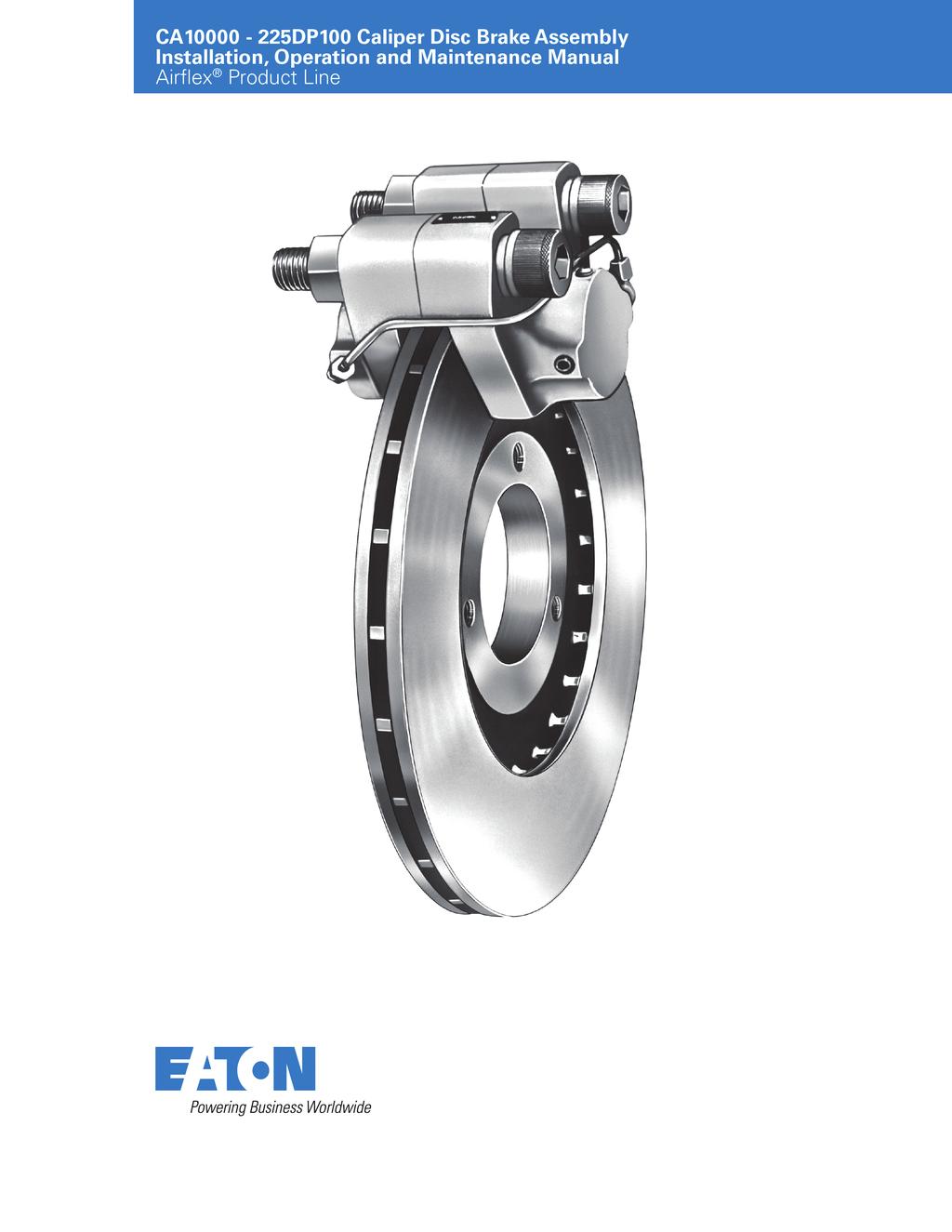
5 1.0 INTRODUCTION Throughout this manual there are a number of HAZARD WARNINGS that must be read and adhered to in order to prevent possible personal injury and / or damage to equipment. Three signal words "DANGER", "WARNING", and "CAUTION" are used to indicate the severity of a hazard, and are preceded by the safety alert symbol. Danger Denotes the most serious hazard, and is used when serious injury or death WILL result from misuse or failure to follow specific instructions. Used when serious injury or death MAY result from misuse or failure to follow specific instructions. Used when injury or product / equipment damage may result from misuse or failure to follow specific instructions. It is the responsibility and duty of all personnel involved in the installation, operation and maintenance of the equipment on which this device is used to fully understand the! Danger,!, and! procedures by which hazards are to be avoided. 1.1 Description The Eaton Airflex 225DP100 caliper disc brake assembly is ideally suited for many high torque, high energy stopping applications. By properly choosing actuating pressure, number of calipers per disc, number of discs and disc diameter, a braking system can be custom designed for a wide variety of applications The Airflex 225DP100 caliper disc brake assembly is supplied with long wearing, NON-ASBESTOS friction material The Airflex 225DP100 caliper disc brake assembly is of the opposed piston design. This design permits fixed mounting of the 225DP100 caliper disc brake assembly and the disc. Symmetrical split construction of the piston housing permits a center reaction mounting and the ability to accommodate discs of different thicknesses. Friction shoe assemblies (7) attach to the 225DP100 caliper disc brake actuating pistons (8) and are replaceable without disturbing the caliper mounting. Applying hydraulic or pneumatic pressure to the piston cylinders causes the piston-mounted friction shoes assemblies to clamp the disc, developing the braking torque. The braking power is directly proportional to the applied pressure and disc diameter The 225DP100 caliper disc brake assembly can be pneumatically or hydraulic actuated. The pressurizing media must be specified to insure proper piston seal compatibility. Two types of seals (22) are available: one for air and mineral base fluids, and the other for vegetable base fluids Low coefficient friction shoe assemblies (7) are available which permit the 225DP100 caliper disc brake assembly to be used as tension brakes Maximum allowable operating pressure is 1000 psig (69 bar). For those installations not equipped with a highpressure power source, a pressure intensifier can be used to provide the required pressure. This device converts a low air pressure input into a high hydraulic pressure output This manual includes metric equivalents usually shown in parentheses (#) following the U.S. measurement system value The disc that the 225DP100 caliper disc brake assembly engages on can be purchased or manufactured by the end user. A limited number of discs are available from Eaton. Contact your local distributor for details. 1.2 How It Works Throughout this manual, explanations mentioning specific components of the 225DP100 caliper disc brake assembly are often followed by numbers in parentheses, which refer to the item numbers in Table 1 and on Figures 1, 2 and 3; for example, friction shoe assembly (7) Air or hydraulic pressure is introduced into the cylinder blocks at one of the two inlet openings (16). The bridge pipe (10) connects the two cylinders (11), assuring equal pressure on both sides. Both pistons (8) move simultaneously and squeeze the piston-mounted friction shoe assemblies (7) against the disc, causing a braking action When the actuation pressure is released to zero psig (zero bar), a spring-powered, self-adjusting release mechanism retracts the pistons and associated friction shoes from the disc The shoe retraction and self-adjusting mechanism is contained inside of the caliper piston (8). The assembly is completely inside the caliper cylinder block (11) and is not subject to tampering or contamination by foreign matter. The wear adjustments are done automatically and no maintenance is required throughout the life of the friction shoes. See Figure The 225DP100 caliper disc brake assembly is self-adjusting compensate for friction material wear and maintains a constant running clearance between the friction shoes assemblies and disc. They also maintain a constant displacement volume and therefore a constant response time for each of the 225DP100 caliper disc brake assembly s engagement. EATON CA DP100 Caliper Disc Brake Assembly Installation, Operation and Maintenance Manual E-CLCL-TT003-E August
6 1.2.5 A detailed description of the operation of the retractor mechanism is as follows: Pin (8) is fixed to the cylinder block (11) by snap ring (19). Piston (8) is positioned by the retaining rings (21) which slide along pin (1). Spring (15) is retained in the piston by washer (4) and snap ring (20). The force required to slide the retaining rings along the pin is greater than the force developed by the spring When pressure is applied, the piston moves outward, compressing the spring until the washer (4) bottoms against the spring guide (3). The pressure, acting on the piston diameter, forces the retaining rings outward along the pin. When pressure is removed, the retaining rings maintain their new position on the pin. The spring then retracts the piston until the spring guide bottoms against the piston (8). The gap between the spring guide and washer is equal to the clearance between the disc and friction pad. 2.0 INSTALLATION Prior to installation of the 225DP100 caliper disc brake assembly, the machinery shall be locked in a secured position. Failure to do so could result in serious personal injury or possibly death. 2.1 Preparation Varying disc thicknesses can be accommodated by inserting spacers between the two cylinder blocks (11). Note: Varying the disc thickness will require new or modification of the bridge piping. Note: Minimum disc diameter is 9.93 (240 mm). A standard disc thickness of the tolerance is / (25.5 mm) (+0.00 mm / mm) Inserting spacers between the two cylinder blocks will require new/modification of the bridge piping If a 225DP100 caliper disc brake assembly mounting bracket is fabricated, it must allow the 225DP100 caliper disc brake assembly to butt against the lip adjacent to its machined surface. This bracket must also be of sturdy construction and rigidly mounted to prevent deflection during operation. It is recommended that two tapped holes (1 8NC-3 thread) be provided with enough thread engagement allowing the socket head screws (12) to be tightened at 590ft. /lbs. (800 Nm). If thru holes are fabricated into the mounting bracket the hole size should be 1-1/32 (26.2 mm) maximum. Before locating the holes for drilling in the mounting bracket, make sure the 225DP100 caliper disc brake friction shoe assemblies (7) will completely engage the disc. The friction material should not overhang the outer edge of the disc. The outside diameter (O.D.) of the disc must not rub against the cylinder block (11). See Figure 4. 6 EATON CA DP100 Caliper Disc Brake Assembly Installation, Operation and Maintenance Manual E-CLCL-TT003-E August 2015
7 0.03" min gap during operation both sides Place feeler gage to verify equal.062" gap between friction lining and disc during installation Mounting surface 2.2 Mounting the 225DP100 caliper disc brake assembly The disc should be installed prior to mounting the 225DP100 caliper disc brake assembly. The maximum allowable runout of the disc should be verified to be no greater than (0.25 mm). Disc must extend past edge of the friction linings The 225DP100 caliper disc brake assembly can be installed using mounting surfaces located on either side of the 225DP100 caliper disc brake assembly. See Figure It is very important that the mounting bracket be properly aligned with the mounting surface of the 225DP100 caliper disc brake assembly. For proper operation and service life, alignment of the mounting flange to the shaft of the disc gear should be held within the limits shown on Figure 4. Note: that concentricity and perpendicularity values in Figure 4 are expressed as TIR (Total Indicator Reading) values. 7 Disc to be within.010 T.I.R of mounting surface Before final tightening of the mounting screws, engage the 225DP100 caliper disc brake assembly, tighten the screws, release the 225DP100 caliper disc brake assembly and check that the alignment is within the values in Figure 4. Figure 4 The nuts (14) provided with the 225DP100 caliper disc brake assembly for permanent mounting or assembly is grade 8. These nuts provided prior to February 2015 were for shipping purposes and were grade 2, and are not capable of being tightened to the required torque value. It is recommended to verify the grade nut with the 225DP100 caliper disc brake assembly The friction shoe assemblies (7) should be protected from contamination by oil, grease, dirt or excessive moisture. Contamination of the friction material could result inerratic or loss of torque Verify or set the initial gap between the friction shoes assemblies and the disc to approximately (1.6 mm). See figure After final tightening of the mounting screws, apply the 225DP100 caliper disc brake assembly and release the 225DP100 caliper disc brake assembly. Then recheck that the alignment is within the values in Figure 4. When the bridge pipe (10) is installed it passes across the top of one of the cylinder blocks (11) before attaching to the other cylinder block. DO NOT mount the 225DP100 caliper disc brake assembly on the side where the bridge pipe would cause interference. Note: The 225DP100 caliper disc brake assembly is symmetrical to avoid the bridge pipe interference. The unit can be positioned for either direction of rotation as required. Note: For hydraulic actuation installations, install the 225DP100 caliper disc brake assembly with the bleeder holes as high as possible to allow for the removal of the air from the hydraulic system. See Figure 1 and Table The socket head screws (12) and locking washers (13) are furnished to mount the 225DP100 caliper disc brake assembly, and should be tightened to the appropriate torque value. See Table 2. Table 2 Fastener Description and Assembly Torque - ft.-lb. (Nm) Item Description Specification 225DP Socket Head Mounting Screw Size 1"-8 NC-3 Quantity 2 Torque, Lubed 590 (800) 12 Hex Head Cap Screw Size 1/4-20 NC-2 Quantity 8 Torque, Dry 7 (10) EATON CA DP100 Caliper Disc Brake Assembly Installation, Operation and Maintenance Manual E-CLCL-TT003-E August
8 2.3 Actuating Supply Systems Maximum allowable pressure is 1000 psig (69 bar). Application of pressure exceeding maximum allowable may result in damage to the 225DP100 caliper disc brake assembly Actuation medium can be supplied to the 225DP100 caliper disc brake assembly via one of the tapped holes in the cylinder block (11) or thru the bleed holes (23). See Figure 1 and 2. Pipe diameter is 1/ It is recommended that the piping connecting the actuating media to the 225DP100 caliper disc brake assembly be rated for the appropriate system pressures. Maximum allowable operating pressure is 1000 psig (69 bar) Before assembly the actuation medium piping should be cleaned internally Hydraulically actuated systems require removal of air from the system when filling the system with the correct hydraulic fluid upon installation of the 225DP There are two bleed screws (23) on the cylinder blocks (11). See Figure 1. The bleed screw on each of the two cylinders which are located at the highest level will be used to remove the air from the hydraulic fluid to the 225DP100 caliper disc brake assembly The mineral based fluid compatible seals are made from 366-Y-Buna-N material. Typical examples of mineral based fluids are hydraulic fluids and automotive automatic transmission fluids. Suggested fluids are: Mobil 24DTE Hydraulic Fluid Napa Automatic Transmission Fluid The vegetable based fluid compatible seals are made from Buna-S (476S-GRS) material. Automotive brake fluid (DOT 3) is a typical example of vegetable based fluid. Suggested fluids are: Wagner 21B Brake Fluid Napa DOT 3 Brake Fluid Loosen the selected bleed screw and apply enough hydraulic pressure allow all the air and a small amount of fluid to escape Retighten bleed screw once all air has been removed from the system. Use the appropriate personal protective equipment (PPE). Re-tighten the bleed screw (23) before releasing the applied pressure to avoid sucking more air back into the system. 3.0 OPERATION Ensure adequate safety guarding is installed prior to operation. 3.1 Conditions of Operation Friction material must be worn-in to achieve the 225DP100 caliper disc brake assembly s torque rating. For new installations or after repair, a minimum wear-in period may be required. Wear-in periods will very dependent on system pressure, disc diameter, finish, speed and material type Verify proper operation before putting the product into service. Protective means must be used to prevent oil, grease, dirt or coolant from coming into contact with the surfaces of the friction material. Oil or grease on these parts will significantly reduce the torque capacity of the 225DP100 caliper disc brake assembly. Do not risk personal injury or damage to the equipment. Operation at disc speeds and temperatures exceeding the maximum allowable by the friction material may result in exposure to personal injury or product/equipment damage. Consult the Airflex catalog or factory for the appropriate calculations. 3.2 Pressure, Speed, and Temperature Limits Maximum applied pressure is 1000 psig (69 bar) Due to the spring force, a minimum pressure of 8 psig (0.55 bar) is required to engage the friction shoes Maximum temperatures are application dependent. Consult the Airflex catalog or factory for the appropriate calculations. Operation at disc speeds and temperatures exceeding the maximum allowable by the friction material may result in exposure to personal injury or product/equipment damage. Consult the Airflex catalog or factory for the appropriate speed and temperature calculations. 3.3 Wear in Procedure The 225DP100 caliper disc brake assembly friction material will normally require a short wear-in period before generating full rated torque. Wear-in periods will very dependent on system pressure, disc diameter, finish, speed and material type Verify proper operation before putting the product into service. 8 EATON CA DP100 Caliper Disc Brake Assembly Installation, Operation and Maintenance Manual E-CLCL-TT003-E August 2015
9 3.4 Periodic Inspection Periodic inspection will vary upon the specific wear rate per application. Periodic inspection intervals should be defined by maintenance or qualified personnel Inspect the friction material for wear as shown in Figure 5. If wear meets or exceeds the limits in Figure 5 proceed to section 4.3 for friction shoe replacement. 4.0 MAINTENANCE When replacing components, use only genuine, Airflex replacement parts. Use of other materials may severely affect performance. 4.1 Periodic maintenance Bleeding the hydraulic system Max wear.125 Max wear There are two bleed screws (23) on the cylinder blocks (11). Select the bleed screw on each of the two cylinders which are located at the highest level. Use the appropriate personal protective equipment (PPE) Gently loosen the selected bleed screw and apply enough actuation hydraulic pressure to allow the air and a small amount of fluid to escape Retighten bleed screw once air has been removed from the system. Re-tighten the bleed screw (23) before releasing the applied pressure to avoid draining more air back into the system..46 New Disc Figure 5.46 New Inspect the 225DP100 caliper disc brake assembly for leaking actuation fluid. Should actuation fluid be leaking from the boot proceed to section 4.4 for seal replacement Inspect the 225DP100 caliper disc brake assembly for retraction of the piston assembly. Should the piston assembly not be retracting then proceed to section 4.5 for piston assembly replacement Repeat section to on both 225DP100 caliper disc brake assembly cylinders, and as many times as necessary to remove all the air bubbles from the system. Note: Always bleed the system in a sequence starting from the point closest to the actuator and in succession at points further away. During the bleeding operation, make sure that an adequate supply of fluid is available to prevent air from entering the system. 4.2 Wear Limits Wear Limit for the 225DP100 caliper disc brake assembly friction material is shown in Figure 5. If the friction material wear limit has been reached or exceeded, replace the friction shoe assembly as required. 4.3 Friction Shoe Assembly Inspection & Replacement Prior to the removal or installation of the 225DP100 caliper disc brake assembly friction shoe assembly the machinery shall be locked in secured position and that actuating systems are actually locked out or disconnected to prevent accidental actuation during maintenance. Failure to do so could result in serious personal injury or possibly death. EATON CA DP100 Caliper Disc Brake Assembly Installation, Operation and Maintenance Manual E-CLCL-TT003-E August
10 Use only genuine, Airflex friction material. Use of friction material not of Airflex origin may result in unpredictable 225DP100 caliper disc brake assembly performance and/ or excessive wear of the 225DP100 caliper disc brake assembly components. Note: There are no wear adjustments necessary with the 225DP100 caliper disc brake assembly Inspect the friction material to ensure that it is clean and free from oil and grease. Measure the material thickness for wear. See Figure 5 and to determine if the friction shoe assemblies require replacement. A new friction shoe assembly is 21/32 (16.7 mm) not including the steel backing plate. When the material thickness is worn to approximately 9/32 (7.4 mm) or within 1/8 (3.2 mm) of the mounting slot in the friction material, new friction shoe assemblies should be installed. Damage to the piston will result if the material is allowed to wear beyond this point. Contamination of the friction material could result inerratic or loss of torque. Failure to replace the friction shoe assemblies as a set may result in damage to the 225DP100 caliper disc brake assembly and possible 225DP100 caliper disc brake assembly malfunction, degrading the stopping performance and ability to secure the load Friction material replacement Verify that the wear limit has been reached as shown in Figure 5. Note: The 225DP100 caliper disc brake assembly does not require removal in order to replace friction material. Note: Inspect the surface of the disc for minimum thickness and condition. Replace or resurface the disc a required With the actuation pressure off, remove the four hex cap screws (23), lock washers (25), and friction shoe retainers (5) to allow the removal of the friction shoe assemblies (7) Press the piston (8) all the way back in the cylinder. It may be necessary to loosen the bleed screws as shown in Figure 1 on the cylinder block (11) to bleed off the actuation pressure Install the friction shoe assemblies (7) by sliding the friction shoe assembly over the piston (8), and installing the friction shoe assembly retainer (5) with the hex head cap screws (23) and lockwashers (25). See Figure Seal Replacement Only qualified maintenance personnel should replace the boot or quad rings. Faulty workmanship may result in possible personal injury, 225DP100 caliper disc brake assembly malfunction or damage to the machinery. Before proceeding, make sure that the correct seal kit is being used for the seal replacement. The quad ring (24) is designed to be used with a particular actuating medium; either air/mineral oil or vegetable base fluid. Proper kit part numbers for the different actuating medium are noted in section 8.1. Use only genuine Airflex parts. Use of non-original Airflex parts may result in unpredictable performance The 225DP100 caliper disc brake assembly must be removed from the machinery in order to replace the boot (9) or quad ring (24) Remove friction shoe assemblies (7) as explained in section Remove the piston (8) and the boot (9). Clean the dust boot grooves in the cylinder block (11). Keep dust boot groove free of contamination Remove the quad ring (24) from the piston. Using seal kits with incompatible fluid will result in quad ring damage. Refer to Section Coat the new quad ring (24) with compatible type of oil, and place it carefully into the piston (8) groove Make sure quad ring (24) is properly seated in its groove. See Figure Insert the original piston assembly carefully in cylinder bore and over pin (1) retained in cylinder block (11) from previous usage. Do not damage lips of quad ring (24). Damage may result in leaks or erratic operation Apply rubber to iron adhesive such as Eastman 910 or equivalent into the groove in the bore of the cylinder block. Carefully insert the outer diameter of the boot (9) into the groove in the bore of the cylinder block Note: In older 225DP100 caliper disc brake assembly designs, the cylinder block has a counter bore instead of a groove. When working on these older designs, the boot should be bonded to the counter bore using a good grade of rubber-to-iron adhesive. 10 EATON CA DP100 Caliper Disc Brake Assembly Installation, Operation and Maintenance Manual E-CLCL-TT003-E August 2015
11 4.4.9 Press the piston into the cylinder block until fully inserted. It may be necessary to loosen the bleed screws (23)as shown in Figure 1 on the cylinder block (11) to bleed off the pressure to fully insert the piston (8) Install the friction shoe assemblies (7) by sliding the friction shoe assembly over the piston (8), and installing the friction shoe retainer (5). 4.5 Piston Replacement Only qualified maintenance personnel should replace the piston. Faulty workmanship may result in possible personal injury, 225DP100 caliper disc brake assembly malfunction or damage to the machinery. Before proceeding, make sure that the correct piston kit is being used for the piston replacement. The quad ring (24) is designed to be used with a particular actuating medium; either air/mineral oil or vegetable base fluid. Proper kit part numbers for the different actuating medium are noted in section 8.2. Use only genuine Airflex friction material. Use of non-original Airflex material may result in unpredictable performance. Do not damage lips of quad ring (24). Damage may result in leaks or erratic operation Apply rubber to iron adhesive such as Eastman 910 or equivalent into the groove in the bore of the cylinder block. Carefully insert the outer diameter of the boot (9) into the groove in the bore of the cylinder block Note: In older 225DP100 caliper disc brake assembly designs, the cylinder block (11) has a counter bore instead of a groove. When working on these older designs, the boot should be bonded to the counter bore using a good grade of rubber-to-iron adhesive Press piston (8) into cylinder block (11) until fully inserted. It may be necessary to loosen the bleed screws (23) as shown in Figure 1 on the cylinder block to bleed off the pressure to fully insert the piston Install the friction shoe assemblies (7) by sliding the friction shoe assembly over the piston (8), and installing the friction shoe assembly retainer (5) with the hex head cap screws (23) and lockwashers (25). See Figure For fluid actuation bleed the system per Section The 225DP100 caliper disc brake assembly must be removed from the machinery in order to replace the piston assembly or quad ring Remove friction shoe assemblies (7) as explained in section Remove the piston (8) and the boot (9). Clean the dust boot grooves in cylinder block (11). Keep dust boot groove free of contamination Remove the quad ring (24) from the piston. Using quad rings or piston kits with incompatible fluid will result in quad ring damage Install the new pin (1) and retain with the new snap ring (19) into the cylinder block (11) Coat the new quad ring (24) with compatible type of oil, and place it carefully into the quad ring groove Make sure quad ring (24) is completely seated in its groove Insert the new piston assembly carefully in cylinder bore and over pin (1) retained in cylinder block (11). EATON CA DP100 Caliper Disc Brake Assembly Installation, Operation and Maintenance Manual E-CLCL-TT003-E August
12 5.0 ACCESSORIES 5.1 Pressure Intensifiers Air over Hydraulic Description For those installations that require but are not equipped with a high hydraulic pressure power source, a pressure intensifier can be used to provide the required pressure. This device multiplies a low air pressure input into a higher hydraulic pressure output Airflex supplied pressure intensifiers for the Airflex 225DP100 caliper disc brake assemblies are designed for industrial caliper brakes which require low initial hydraulic displacement prior to full pressure application, and require near zero residual system pressure. They are intended for single stop and low cyclic duty. They multiply a low air pressure input into a higher hydraulic pressure output. 6.0 ORDERING INFORMATION/TECHNICAL ASSISTANCE 6.1 Equipment Reference In any correspondence regarding Eaton Airflex Equipment, refer to the information on the product nameplate and call or write: Eaton Corporation Hydraulics Group USA Airflex Products 9919 Clinton Road Cleveland, Ohio Tel.: (216) Fax: (216) Hydraulic to air pressure Ratio is 15: Actuation Fluid Airflex-supplied intensifiers are compatible with vegetable base hydraulic fluids only. Using non-vegetable base hydraulic fluid will result in damage to intensifier Intensifier model 153x0772 is designed for use with one 225DP100 caliper disc brake assembly. Intensifier model 153x1135 is designed for use with 2 or more 225DP100 caliper disc brake assemblies to be engaged at the same time. Using the incorrect number of 225DP100 caliper disc brake assemblies on a system designed with either the intensifier model 153x0772 which is designed for use with one 225DP100 caliper disc brake assembly or 153x1135 which is designed for use with 2 or more 225DP100 caliper disc brake assemblies engaged at the same time may result in either inadequate performance or damage to the caliper components. 12 EATON CA DP100 Caliper Disc Brake Assembly Installation, Operation and Maintenance Manual E-CLCL-TT003-E August 2015
13 7.0 PARTS (STANDARD) 7.1 Basic Assemblies 225DP100 Standard 225DP100 Standard 225DP100 Slip 225DP100 Slip Friction Linings Friction Linings Friction Linings Friction Linings /w Veg. Seals /w Min. Seals /w Veg. Seals /w Min. Seals Item Description H (512123) J (512124) W (513215) C (512463) Part Number Quantity Part Number Quantity Part Number Quantity Part Number Quantity 1 Pin Sleeve Spring Guide Washer Friction Shoe Retainer Friction Shoe Assembly Piston Boot Bridge Pipe Cylinder Block Socket Head Screw X X X X Lockwasher X X X X Hex Nut (Shipping Purposes Only) X X X X Spring X X X X Pipe Plug X X X X Degree Elbow X X X X Elbow X X X X Snap Ring X X X X Snap Ring X X X X Retaining Ring X X X X Dyna Seal X X X X Hex Head Cap Screw X X X X Quad Ring X X X X Lockwasher X X X X EATON CA DP100 Caliper Disc Brake Assembly Installation, Operation and Maintenance Manual E-CLCL-TT003-E August
14 8.0 KITS 8.1 Seal Kit Model Kit P/N Description Boot (9) Quad Ring (24) 225DP YB Part No x0006 Vegetable Quantity DP XB Part No x0007 Mineral Quantity Piston Replacement Kit Model Kit P/N Description Pin Sleeve Spring Washer Piston Boot Spring Snap Snap Retaining Quad (1) (2) Guide (3) (4) (8) (9) (15) Ring (19) Ring (20) Ring (21) Ring (24) 225DP X Part No X X X X X0007 Quantity DP Y Part No X X X X X0006 Quantity Note: Items 2,3, 4, 8, 9, 15, 20, 24 come as a complete assembly 8.3 Friction Shoe Assemblies Model Description Friction Shoe Assembly 225DP100 Part No Standard Friction Linings Quantity 2 225DP100 Part No Slip Friction Linings Quantity 2 14 EATON CA DP100 Caliper Disc Brake Assembly Installation, Operation and Maintenance Manual E-CLCL-TT003-E August 2015
15 9.0 REVISIONS Original Publication Date: April 1995 Revision Date Change Page EATON CA DP100 Caliper Disc Brake Assembly Installation, Operation and Maintenance Manual E-CLCL-TT003-E August
16 Eaton Hydraulics Group USA Airflex Division 9919 Clinton Road Cleveland, OH Tel: Fax: Eaton Hydraulics Group Asia Pacific Airflex Division 281 Fa Sai Road Waigaoqiao Free Trade Zone Shanghai China Tel:(+8621) Fax:(+8621) Eaton All Rights Reserved Printed in USA Document No. E-CLCL-TT003-E August 2015
Airflex DPA Caliper Brake CA Installation, operation and maintenance manual
 CA 10020 Installation, operation and maintenance manual 204204 General information!! Forward this manual to the person responsible for Installation, Operation and Maintenance of the product described herein.
Caliper Disc Brakes. Description H-1. Technical Data and Selection Procedure H DP100 Caliper H-4. HC3 and HD3 Calipers H-7
 Eaton Corporation Airflex Division 9919 Clinton Road Cleveland, Ohio 44144-1077 Caliper Disc Brakes H Phone (216) 281-2211 Fax: (216) 281-3890 Description H-1 Technical Data and Selection Procedure H-2
QRV 9100 Airflex Quick release valve Installation, operation and maintenance of Airflex Quick release valve
 Airflex Quick release valve 203977 Installation, operation and maintenance of Airflex Quick release valve Table of Contents Section Description Page No. AIRFLEX QUICK RELEASE VALVE 3 1.0 INTRODUCTION 4
FHB 8110 Brake Assemblies Installation, Operation and Maintenance Manual Airflex
 FHB 8110 Brake Assemblies Installation, Operation and Maintenance Manual Airflex General Information Forward this manual to the person responsible for Installation, Operation and Maintenance of the product
Installation, Operation and Maintenance of Airflex Models AD, ADP, BD and FDA Rotorseals
 RS 9040 Warning Forward this manual to the person responsible for Installation, Operation and Maintenance of the product described herein. Without access to this information, faulty Installation, Operation
Installation, operation and maintenance of Airflex DBA brake assemblies DBA 8080
 Installation, operation and maintenance of Airflex DBA brake assemblies DBA 8080 ! Warning Forward this manual to the person responsible for Installation, Operation and Maintenance of the product described
Installation, Operation and Maintenance of Airflex Quick Release Valve
 QRV 9100 Forward this manual to the person responsible for Installation, Operation and Maintenance of the product described herein. Without access to this information, faulty Installation, Operation or
WCSB tensioner / brake with ORB coolant ports
 General information!! Forward this manual to the person responsible for Installation, Operation and Maintenance of the product described herein. Without access to this information, faulty Installation,
WCSB tensioner/brake. General information. Warning. Caution
 General information!! Forward this manual to the person responsible for Installation, Operation and Maintenance of the product described herein. Without access to this information, faulty Installation,
Installation, Operation and Maintenance of Airflex Model WCSBEP* Tensioner / Brake (for size 36EP)
") WSB 11205 Forward this manual to the person responsible for Installation, Operation and Maintenance of the product described herein. Without access to this information, faulty Installation, Operation or
WSB 11205 Forward this manual to the person responsible for Installation, Operation and Maintenance of the product described herein. Without access to this information, faulty Installation, Operation or
Installation, Operation and, Maintenance of DBBS Brake Assemblies with the Plate Style Disc Centering Option
 DBB8112 A! Warning Forward this manual to the person responsible for Installation, Operation and Maintenance of the product described herein. Without access to this information, faulty Installation, Operation
Airflex DBBS Brake Assemblies Installation, Operation and Maintenance Manual DBB 8110
 Airflex DBBS Brake Assemblies Installation, Operation and Maintenance Manual DBB 8110 General Information Forward this manual to the person responsible for Installation, Operation and Maintenance of the
Installation, Operation and Maintenance of Airflex Model DBB Brake Assemblies
 DBB 8100 Warning Forward this manual to the person responsible for Installation, Operation and Maintenance of the product described herein. Without access to this information, faulty Installation, Operation
WCB WCBD3 Water Cooled Tensioner - Installation, Operation and Maintenance Manual Airflex Product Line
 WCB 11080 WCBD3 Water Cooled Tensioner - Installation, Operation and Maintenance Manual Airflex Product Line General Information Forward this manual to the person responsible for Installation, Operation
Installation, Operation and Maintenance of Airflex Model AMCB AccuStop TM Clutch\Brake Combination
 AMCB 16200 Forward this manual to the person responsible for Installation, Operation and Maintenance of the product described herein. Without access to this information, faulty Installation, Operation
for Installation, Operation and Maintenance of Airflex CS and CSA Brake Assemblies CS 8000 Warning Forward this manual to the person responsible
 CS 8000 Warning Forward this manual to the person responsible for Installation, Operation and Maintenance of the product described herein. Without access to this information, faulty Installation, Operation
Airflex Floating Housing Brake
 Airflex Floating Housing Brake Airflex FHB Brake Elements Dimensional & Technical Data Overview Eaton Airflex has introduced a revolutionary new design in disc brake technology called the Floating Housing
DBB Brake Assemblies. General Information. Warning. Caution
 General Information! Warning! Forward this manual to the person responsible for Installation, Operation and Maintenance of the product described herein. Without access to this information, faulty Installation,
Installation, Operation and Maintenance of Airflex Model WCB2EP* Tensioner / Brake (for size 36EP)
") WCB 11075 Forward this manual to the person responsible for Installation, Operation and Maintenance of the product described herein. Without access to this information, faulty Installation, Operation or
WCB 11075 Forward this manual to the person responsible for Installation, Operation and Maintenance of the product described herein. Without access to this information, faulty Installation, Operation or
CALIPER BRAKE INSTALLATION AND MAINTENANCE MANUAL
 CALIPER BRAKE INSTALLATION AND MAINTENANCE MANUAL WPT Power Corporation 1600 Fisher Road - Wichita Falls, TX 76305 P.O. Box 8148 - Wichita Falls, TX 76307 Ph. 940-761-1971 Fax 940-761-1989 www.wptpower.com
Installation, Operation and Maintenance of the Airflex CH Multiple-Disc Clutch and Brake Assemblies
 HY 13100 Forward this manual to the person responsible for Installation, Operation and Maintenance of the product described herein. Without access to this information, faulty Installation, Operation or
Installation, Operation and Maintenance of the Airflex Model BT Rotorseal Assembly
 RS 9070 Warning Forward this manual to the person responsible for Installation, Operation and Maintenance of the product described herein. Without access to this information, faulty Installation, Operation
Installation, Operation and Maintenance of Airflex 229 DBA Brake Assemblies with Cone-style Disc Centering Option
 DBA 8081 Warning Forward this manual to the person responsible for Installation, Operation and Maintenance of the product described herein. Without access to this information, faulty Installation, Operation
Installation, Operation and Maintenance of the Airflex WCB2 Tensioner / Brake
 WCB 11070 Warning Forward this manual to the person responsible for Installation, Operation and Maintenance of the product described herein. Without access to this information, faulty Installation, Operation
WCB11070 WCB2 Tensioner/Brake Installation, Operation and Maintenance Manual Airflex Product Line
 WCB11070 WCB2 Tensioner/Brake Installation, Operation and Maintenance Manual Airflex Product Line 204182 General Information!! Forward this manual to the person responsible for Installation, Operation
Tidland Air Brake. Installation, Operation, and Maintenance. Models 200, 250, 305, 380, 460, 610
 Tidland Air Brake Installation, Operation, and Maintenance Models 200, 250, 305, 380, 460, 610 TABLE OF CONTENTS TIDLAND CUSTOMER SERVICE... 2 RECOMMENDED TOOLS... 2 CAUTION... 2 INSTALLATION... 3 Caliper
Installation, Operation and Maintenance of Airflex Model AA2, B2, B3 and C2 Rotorseals
 RS 9010 Warning Forward this manual to the person responsible for Installation, Operation and Maintenance of the product described herein. Without access to this information, faulty Installation, Operation
Bray/ VAAS Slurry Series Knife Gate Valve 760/762/765/766/767/768 Series Operation and Maintenance Manual
 Bray/ VAAS Knife Gate Valve 760/762/765/766/767/768 Series Table of Contents Definition of Terms 1 Safety Instructions 1 Introduction 2 Unpacking 2 Storage 2 Installation 3 Commissioning 3 Cylinder-Operated
INSTALLATION INSTRUCTIONS
 INSTALLATION INSTRUCTIONS REAR DISC BRAKE CONVERSION KITS A112, A112-1 & A112-93 1979-93 FORD MUSTANG with 7.5" & 8.8" AXLES Thank you for choosing STAINLESS STEEL BRAKES CORPORATION for your braking needs.
INSTALLATION INSTRUCTIONS
 INSTALLATION INSTRUCTIONS FORCE 10 SPORT R1 REAR DISC CONVERSION KIT A126-50 2005-10 Chevrolet Silverado and GMC Sierra Thank you for choosing STAINLESS STEEL BRAKES CORPORATION for your braking needs.
MODEL 25-OM-10-C & 25-OA-10-C HYDRAULIC BOOSTER
 SPX Corporation 5885 11th Street Rockford, IL 61109-3699 USA Internet Address: http://www.powerteam.com Tech. Services: (800) 477-8326 Fax: (800) 765-8326 Order Entry: (800) 541-1418 Fax: (800) 288-7031
INSTALLATION INSTRUCTIONS
 INSTALLATION INSTRUCTIONS REAR DISC BRAKE CONVERSION KIT A126-1 1973-87 CHEVROLET 1/2 TON 2WD Thank you for choosing STAINLESS STEEL BRAKES CORPORATION for your braking needs. Pleases take the time to
Constricting Type Clutches and Brakes
 Eaton Corporation Airflex Division 9919 Clinton Road Cleveland, Ohio 44144-1077 Phone (216) 281-2211 Fax: (216) 281-3890 Constricting Type Clutches and Brakes Constricting Features B-1 Element Descriptions
INSTALLATION INSTRUCTIONS
 INSTALLATION INSTRUCTIONS REAR DRUM TO DISC BRAKE CONVERSION KIT A118 pre-1985 Ford F150 (except 1983-1984 w/super H/D axle) Thank you for choosing STAINLESS STEEL BRAKES CORPORATION for your braking needs.
SERIES G3DB/AG3DB ELEVATOR
 TM INSTRUCTIONS AND PARTS LIST SERIES G3DB/AG3DB ELEVATOR WARNING This manual, and GENERAL INSTRUCTIONS MANUAL, CA-1, should be read thoroughly prior to pump installation, operation or maintenance. SRM00059
PRODUCT SERVICE MANUAL FOR BK12DHZ PUMPS
 PRODUCT SERVICE MANUAL FOR BK12DHZ PUMPS WARNING This manual, and the GENERAL INSTRUCTION MANUAL SRM00046, should be read thoroughly prior to pump installation, operation or maintenance. Manual No. SRM00095
INSTALLATION INSTRUCTIONS
 INSTALLATION INSTRUCTIONS PERFORMANCE AT THE WHEELS KIT W155-5 CHRYSLER 8 3 /4" & 9 3 /4" REAR AXLES Thank you for choosing STAINLESS STEEL BRAKES CORPORATION for your braking needs. Please take the time
Installation, Operation and Maintenance of Airflex Model DBBS Brake Assemblies
 DBB 8110 Warning Forward this manual to the person responsible for Installation, Operation and Maintenance of the product described herein. Without access to this information, faulty Installation, Operation
minimum allowable level, remove brake fluid to the midway point before proceeding.
 1 of 6 12/7/2011 6:45 PM aution: Refer to Brake Dust Caution in Service Precautions. Caution: Refer to Brake Fluid Irritant Caution in Service Precautions. Removal Procedure 1. Inspect the fluid level
INSTALLATION INSTRUCTIONS
 INSTALLATION INSTRUCTIONS REAR DISC CONVERSION KIT A136-1 1976-86 AMC 20 AXLES WITH WARN FULL FLOATING AXLE CONVERSION Thank you for choosing STAINLESS STEEL BRAKES CORPORATION for your braking needs.
PRODUCT SERVICE MANUAL. BK6DHZ(C)-250, 275, 312 and 400 PUMPS
-250, 275, 312 and 400 PUMPS") PRODUCT SERVICE MANUAL BK6DHZ(C)-250, 275, 312 and 400 PUMPS WARNING This manual, and the GENERAL INSTRUCTION MANUAL, SRM00046, should be read thoroughly prior to pump installation, operation or maintenance.
PRODUCT SERVICE MANUAL BK6DHZ(C)-250, 275, 312 and 400 PUMPS WARNING This manual, and the GENERAL INSTRUCTION MANUAL, SRM00046, should be read thoroughly prior to pump installation, operation or maintenance.
ASSEMBLY INSTRUCTIONS FOR DYNALITE DRAG RACE FRONT HUB KIT WITH DIAMETER SOLID ROTOR PINTO / MUSTANG II
 ASSEMBLY INSTRUCTIONS FOR DYNALITE DRAG RACE FRONT HUB KIT WITH 0.75 DIAMETER SOLID ROTOR 97-978 PINTO / MUSTANG II (FIVE LUG CONFIGURATION ONLY)* PART NUMBER GROUP 0-03-B DISC BRAKES SHOULD ONLY BE INSTALLED
ASSEMBLY INSTRUCTIONS FOR PART NUMBER GROUP
 ASSEMBLY INSTRUCTIONS FOR DYNAPRO 6 BIG BRAKE FRONT HAT KIT, 1.19 DIAMETER VENTED ROTOR 1990-005 ACURA/CIVIC ( LUG) 000-003 CIVIC SI ( LUG) 007 - PRESENT HONDA FIT FOR FACTORY 6 mm DISC SPINDLE PART NUMBER
DODGE INSTRUCTION MANUAL for TAF Pillow Blocks & S-1 Units
 DODGE INSTRUCTION MANUAL for TAF Pillow Blocks & S-1 Units FITTING OR REPLACING A UNIT IN A PILLOW BLOCK WARNING To ensure that drive is not unexpectedly started, turn off and lock out or tag power source
HEVC Installation, operation and maintenance manual Airflex HEVC
 - Installation, operation and maintenance manual Airflex HEVC 5005 204261 General information Warning Forward this manual to the person responsible for Installation, Operation and Maintenance of the product
INSTALLATION INSTRUCTIONS
 INSTALLATION INSTRUCTIONS DISC BRAKE CONVERSION KITS A121-1, A121-2, A121-3, A121-4 1967-69 Ford & Mercury Thank you for choosing STAINLESS STEEL BRAKES CORPORATION for your braking needs. Pleases take
Parking brake Mechanical brake acting on rear wheels
 11 Brake System 11.1 General SPECIFICATIONS EJTC0010 Master cylinder Type Tandem type I.D. mm(in.) 20.64 mm (0.813 in.) Fluid level warning sensor Provided Brake booster Type Vacuum Boosting ratio 4.0
Disassembly and Reassembly for CBB-SR (Spring Return) Series Pneumatic Actuators
 Series Pneumatic Actuators") Part Number: VA001-196-31, Rev. 0 Release: May 2012 Disassembly and Reassembly for CBB-SR (Spring Return) Series Pneumatic Actuators Table of Contents Part Number: VA001-196-31, Rev. 0 May 2012 Table of
Part Number: VA001-196-31, Rev. 0 Release: May 2012 Disassembly and Reassembly for CBB-SR (Spring Return) Series Pneumatic Actuators Table of Contents Part Number: VA001-196-31, Rev. 0 May 2012 Table of
BRAKE SYSTEM Return To Main Table of Contents
 BRAKE SYSTEM Return To Main Table of Contents GENERAL... 2 BRAKE PEDAL... 10 MASTER CYLINDER... 13 BRAKE BOOSTER... 16 BRAKE LINE... 18 PROPORTIONING VALVE... 19 FRONT DISC BRAKE... 20 REAR DRUM BRAKE...
INSTALLATION INSTRUCTIONS
 INSTALLATION INSTRUCTIONS R1 REAR DRUM TO DISC BRAKE CONVERSION KIT A130-3 JEEP CJ SERIES W/AMC-20 REAR AXLES AND 5 x 5-1/2" BOLT CIRCLE Thank you for choosing STAINLESS STEEL BRAKES CORPORATION for your
INSTALLATION INSTRUCTIONS
 INSTALLATION INSTRUCTIONS PERFORMANCE AT THE WHEELS KIT W125-42 GM 10 & 12 Bolt Rear Axles with Staggered or non-staggered Shocks with C-Clips Thank you for choosing STAINLESS STEEL BRAKES CORPORATION
MGM Brakes Service Manual
 MGM Brakes Service Manual MAGNUM Performance Plus Spring Brake Actuators (MJ-Series 3.00 / 76mm Long Stroke ) For: S-Cam Tamper-Resistant MAGNUM Performance Plus Spring Brake Actuators Figure 1 A B C Your
GH-BETTIS SERVICE INSTRUCTIONS DISASSEMBLY & REASSEMBLY FOR MODELS HD521-M4, HD721-M4 AND HD731-M4 DOUBLE ACTING SERIES PNEUMATIC ACTUATORS
 GH-BETTIS SERVICE INSTRUCTIONS DISASSEMBLY & REASSEMBLY FOR MODELS HD521-M4, HD721-M4 AND HD731-M4 DOUBLE ACTING SERIES PNEUMATIC ACTUATORS WITH HYDRAULIC CONTROL PACKAGE PART NUMBER: SE-023 REVISION:
ASSEMBLY INSTRUCTIONS
 ASSEMBLY INSTRUCTIONS FOR DYNALITE PRO SERIES FRONT HUB KIT WITH.75 DIAMETER VENTED ROTOR 970-973 FORD MUSTANG (DRUM / DISC SPINDLE) PART NUMBER GROUP 0-905 WARNING INSTALLATION OF THIS KIT SHOULD ONLY
M-2300-T 6-Piston Mustang Brake Kit INSTALLATION INSTRUCTIONS
 Please visit www.fordracingparts.com for the most current instruction information!!! PLEASE READ ALL OF THE FOLLOWING INSTRUCTIONS CAREFULLY PRIOR TO INSTALLATION. AT ANY TIME YOU DO NOT UNDERSTAND THE
INSTRUCTION MANUAL AND PARTS LIST FOR SERIES 8L-630J AND 630M WARNING
 INSTRUCTION MANUAL AND PARTS LIST FOR SERIES 8L-630J AND 630M WARNING READ CA-l AND TIDS INSTRUCTION MANUAL PRIOR TO INSTALLATION, OPERATION OR MAINTENANCE WARNING This Instruction Manual and General Instructions
INSTALLATION INSTRUCTIONS
 INSTALLATION INSTRUCTIONS REAR DISC BRAKE CONVERSION KIT A157 1991-2004 Dodge Dakota 2WD 1991-2002 Dodge Dakota 4WD 1998-2002 Dodge Durango Thank you for choosing STAINLESS STEEL BRAKES CORPORATION for
Disassembly and Reassembly for CBB (Double Acting) Series Pneumatic Actuators
 Series Pneumatic Actuators") MECATORK S.A.S Release: May 2012 Disassembly and Reassembly for CBB (Double Acting) Series Pneumatic Actuators MECATORK S.A.S Table of Contents May 2012 Table of Contents Section 1: Introduction 1.1 General
MECATORK S.A.S Release: May 2012 Disassembly and Reassembly for CBB (Double Acting) Series Pneumatic Actuators MECATORK S.A.S Table of Contents May 2012 Table of Contents Section 1: Introduction 1.1 General
INSTRUCTION MANUAL IM-422 For HTC/COUPLING ASSEMBLY HC-8088
 No Revision 2/22/18 INSTRUCTION MANUAL IM-422 HTC/COUPLING ASSEMBLY The Riverhawk Company reserves the right to make changes updating this document without dissemination or notice. The latest revision
INSTALLATION INSTRUCTIONS
 INSTALLATION INSTRUCTIONS REAR DISC CONVERSION KIT A128-4 1997-2004 JEEP WRANGLER (TJ) WITH DANA 44 AXLES (non-abs) Thank you for choosing STAINLESS STEEL BRAKES for your braking needs. Pleases take the
INSTALLATION INSTRUCTIONS PERFORMANCE AT THE WHEELS KIT W125
 INSTALLATION INSTRUCTIONS PERFORMANCE AT THE WHEELS KIT W125 1968-81 CAMARO & FIREBIRD 10 & 12 BOLT W/"C" CLIPS Thank you for choosing STAINLESS STEEL BRAKES CORPORATION for your braking needs. Pleases
Instruction Manual for HSPA Take-Up Units
 Installation Instruction Manual for HSPA Take-Up Units Warning: To ensure the drive is not unexpectedly started, turn off and lockout the power source before proceeding. Failure to observe these precautions
Spring-Engaged/Hydraulically-Released BD Caliper Brake. (i) MTY (81) QRO (442) MEX (55)
 MTY (81) QRO (442) MEX (55)") Spring-Engaged/Hydraulically-Released BD Caliper Brake (i) FORM NO. L-07-E-0300 In accordance with Nexen s established policy of constant product improvement, the specifications contained in this manual
Spring-Engaged/Hydraulically-Released BD Caliper Brake (i) FORM NO. L-07-E-0300 In accordance with Nexen s established policy of constant product improvement, the specifications contained in this manual
Single Post Caliper Brake VC500
 Single Post Caliper Brake VC500 1 In accordance with Nexen s established policy of constant product improvement, the specifications contained in this manual are subject to change without notice. Technical
INSTALLATION INSTRUCTIONS
 INSTALLATION INSTRUCTIONS FX4 ELITE REAR DISC CONVERSION KITS WITH INTERNAL PARKING BRAKE A110-14, A111-25, A111-29 for FORD 8" & 9" REAR ENDS Thank you for choosing STAINLESS STEEL BRAKES CORPORATION
Airflex Spring Applied Brakes
 Airflex Spring Applied Brakes CS and CSA Brake Elements... 232 Technical and Dimensional Data... 233 Applications... 235 Component Parts... 237 CTE Brake Elements... 239 Technical and Dimensional Data...
INSTALLATION INSTRUCTIONS R1 REAR CONVERSION KIT
 INSTALLATION INSTRUCTIONS R1 REAR CONVERSION KIT INSTRUCTION FOR ASSEMBLY OF JEEP CJ SERIES W/AMC 20 REAR AXLES, 5 x 5-1/2" BOLT CIRCLE WITH A130-4 FULL FLOATING AXLE OR A130-5 (1 PIECE AXLE) Thank you
Maintenance Instructions & Parts List
 Maintenance Instructions Actuators Maintenance Instructions & Parts List Provide Model Number and Serial Number When Ordering Spare Parts. General Limit the maximum operational pressure of the Parker M
DISC BRAKE/DUAL MASTER CYLINDER CONVERSION. Tools, Equipment and Supplies Needed:
 Please take the time to read the enclosed instructions carefully. If you have any questions, call our Product Assistance personnel for clarification. It is important to note that these instructions contain
BLACKMER PISTON AIR/RELIEF VALVE (w/o spring) CONVERSION KIT SAFETY DATA. For Pump Models: TXH3C, TXH3B, TXH3A, TXD2.5A, TXD1225A
 CONVERSION KIT SAFETY DATA. For Pump Models: TXH3C, TXH3B, TXH3A, TXD2.5A, TXD1225A") BLACKMER PISTON AIR/RELIEF VALVE (w/o spring) CONVERSION KIT INSTALLATION OPERATION & MAINTENANCE INSTRUCTIONS WITH PARTS LIST For Pump Models: TXH3C, TXH3B, TXH3A, TXD2.5A, TXD1225A 964608 Page 1 of 8
BLACKMER PISTON AIR/RELIEF VALVE (w/o spring) CONVERSION KIT INSTALLATION OPERATION & MAINTENANCE INSTRUCTIONS WITH PARTS LIST For Pump Models: TXH3C, TXH3B, TXH3A, TXD2.5A, TXD1225A 964608 Page 1 of 8
INSTALLATION INSTRUCTIONS
 INSTALLATION INSTRUCTIONS REAR DISC BRAKE CONVERSION KIT A125-2 1955-70 FULL SIZE CHEVROLET Thank you for choosing STAINLESS STEEL BRAKES CORPORATION for your braking needs. Pleases take the time to read
MGM Brakes Service Manual
 MGM Brakes Service Manual MODEL LTR-T - 2.50 Pre 6/1/98 MODEL LTR-T - 2.50 Post 5/31/98 MODEL LTR-L3-3.00 For: Long Life Integral Release Bolt Double Diaphragm Spring Brakes Several design improvements
Installation Operation Maintenance. LSSN Butterfly Valve AGA Approved 50MM - 150MM. QAD#IM6055.REVA
 LSSN Butterfly Valve Installation Operation Maintenance Licence Number: 5326 www.challengervalves.com.au 1 Index 1. INTRODUCTION 1.1 Design Features 3 1.2 Flange and Pipe Compatibility 4 1.3 Operating
INSTALLATION INSTRUCTIONS
 INSTALLATION INSTRUCTIONS REAR DISC BRAKE CONVERSION KIT A125-3 1965-72 GM A-BODY 10 & 12 BOLT AXLES Thank you for choosing STAINLESS STEEL BRAKES CORPORATION for your braking needs. Pleases take the time
OVERLOAD CLUTCHES FOR INDEX DRIVES
 The Driving Force in Automation OVERLOAD CLUTCHES FOR INDEX DRIVES WARNING WARNING This is a controlled document. It is your responsibility to deliver this information to the end user of the CAMCO indexer.
ASSEMBLY INSTRUCTIONS
 ASSEMBLY INSTRUCTIONS FOR DYNALITE PRO SERIES REAR PARKING BRAKE KIT WITH.9 DIAMETER VENTED ROTOR (. OFFSET) 005 - PRESENT MUSTANG 8.8 (5 LUG) PART NUMBER GROUP 0-98 INSTALLATION OF THIS KIT SHOULD ONLY
MGM Brakes Service Manual
 MGM Brakes Service Manual For: S-Cam Piston Type Service and Spring Brake Chambers Form No. 5009 Issued 6/91 - Revised 4/2010 MODEL MB-T SERIES MODEL MG-T SERIES Superseded by the MJS SERIES Form #5044
INSTALLATION INSTRUCTIONS
 INSTALLATION INSTRUCTIONS PERFORMANCE AT THE WHEELS KIT W120-22, W120-23 1964 1/2-69 MUSTANG Thank you for choosing STAINLESS STEEL BRAKES CORPORATION for your braking needs. Pleases take the time to read
ASSEMBLY INSTRUCTIONS
 ASSEMBLY INSTRUCTIONS FOR FORGED SUPERLITE BIG BRAKE FRONT HUB KIT WITH 3.00 DIAMETER VENTED ROTOR 968-969 FORD MUSTANG (DISC BRAKE SPINDLE ONLY) PART NUMBER GROUP 0-950 WARNING INSTALLATION OF THIS KIT
INSTALLATION INSTRUCTIONS
 INSTALLATION INSTRUCTIONS INSTALLATION INSTRUCTIONS FOR A136 REAR DRUM TO DISC BRAKE CONVERSION KIT for 1970-75 Jeep, CJ SERIES with Dana 44 flanged axle Thank you for choosing STAINLESS STEEL BRAKES CORPORATION
Airflex. Airflex CBC Clutch/Brake Combination. Today s answer for high cyclic, heavy-duty industrial applications. Authorized Distributor
 Airflex Airflex CBC Clutch/Brake Combination Today s answer for high cyclic, heavy-duty industrial applications. Authorized Distributor 26255 Groesbeck Hwy. Warren, MI 48089 U.S.A. 586.775.3000 586.775.3040
INSTALLATION INSTRUCTIONS
 INSTALLATION INSTRUCTIONS REAR DISC BRAKE CONVERSION KIT A158 1994-97 Dodge Ram 1500 (2WD & 4WD) and REAR DISC BRAKE CONVERSION KIT A158-1 1998-01 Dodge Ram 1500 (2WD & 4WD) Thank you for choosing STAINLESS
ASSEMBLY INSTRUCTIONS
 ASSEMBLY INSTRUCTIONS FOR DYNALITE PRO SERIES FRONT HUB KIT WITH.75 DIAMETER VENTED ROTOR 1980-1987 GENERAL MOTORS G BODY DISC SPINDLE PART NUMBER GROUP -508-B WARNING INSTALLATION OF THIS KIT SHOULD ONLY
DODGE USAF 200/300 Direct Mount Pillow Block Bearings
 DODGE USAF 200/300 Direct Mount Pillow Block Bearings These instructions must be read thoroughly before installation or operation. This instruction manual was accurate at the time of printing. Please see
INSTRUCTION MANUAL AND PARTS LIST FOR A3D SERIES PUMPS
 TM INSTRUCTION MANUAL AND PARTS LIST FOR A3D SERIES PUMPS WARNING This Instruction Manual and General Instructions Manual SRM00046, should be read thoroughly prior to pump installation, operation or maintenance.
Airflex product Line CP3131 Grinding Mill Torque Limiting Control for Single Pinion Mills Installation, operation and maintenance manual
 Airflex product Line CP3131 Grinding Mill Torque Limiting Control for Single Pinion Mills Installation, operation and maintenance manual 204269 General information! Warning! Caution This equipment should
A. Arbor The brake lathe shaft upon which the brake drum and rotor are mounted.
 BRAKES UNIT 5: DISC BRAKE DIAGNOSIS AND REPAIR LESSON 4: SERVICE DISC BRAKE ROTORS I. Terms and definitions A. Arbor The brake lathe shaft upon which the brake drum and rotor are mounted. B. Bezel A piece
Dura Force Disc Brake System Service Manual
 TS 20809_a 3501 Shotwell Drive ISO/TS 16949:2002 Registered (PH): 937.743.8125 Franklin, OH 45005 www.waltheremc.com (FX): 937.743.8232 Table of Contents General Description 1 3 Fastener Torque Chart 4
BETTIS SERVICE INSTRUCTIONS DISASSEMBLY AND REASSEMBLY FOR CB-SR-S SEISMIC SPRING RETURN SERIES PNEUMATIC ACTUATORS
 BETTIS SERVICE INSTRUCTIONS DISASSEMBLY AND REASSEMBLY FOR CB-SR-S SEISMIC SPRING RETURN SERIES PNEUMATIC ACTUATORS PART NUMBER: 102264 REVISION: "C" DATE: November 2000 Page 1 of 11 1.0 INTRODUCTION 1.1
Installation, Operation, and Maintenance Manual Full Port Y-Pattern, Bolted Bonnet, Globe and Check Valves
 SMITH VALVES Installation, Operation, and Maintenance Manual Full Port Y-Pattern, Bolted Bonnet, Globe and Check Valves Globe Valve Series: YG80/YG15 Welded Bonnet Globe Valve Series: YG87/YG17 Piston
INSTALLATION INSTRUCTIONS
 INSTALLATION INSTRUCTIONS PERFORMANCE AT THE WHEELS KITS W156-6 & W156-7 1965-74 MOPAR B & E BODY Thank you for choosing STAINLESS STEEL BRAKES CORPORATION for your braking needs. Pleases take the time
Airflex Air Cooled Disc Clutches and Brakes
 Airflex Air Cooled Disc Clutches and Brakes DBA Description... 183 DBA Brake Elements... 185 DBA Technical information... 186 DBB and DBBS Description... 187 DBB Brake Elements... 189 DBB Technical Information...
Valtek Auxiliary Handwheels and Limit Stops
 Valtek Auxiliary s and Limit Stops Table of Contents Page 1 General information 2 Installation 2 Side-mounted handwheels, size 25 and 50 (linear actuators) 3 Side-mounted handwheels, size 100 and 200 (linear
INSTALLATION INSTRUCTIONS
 INSTALLATION INSTRUCTIONS REAR DISC BRAKE CONVERSION KIT A126-3 1988-98 CHEVY K1500 4WD 10" DRUMS Thank you for choosing STAINLESS STEEL BRAKES CORPORATION for your braking needs. Pleases take the time
INSTALLATION INSTRUCTIONS
 INSTALLATION INSTRUCTIONS REAR DISC CONVERSION KIT A126-2 1988-98 C1500 2WD 10" REAR DRUM Thank you for choosing STAINLESS STEEL BRAKES CORPORATION for your braking needs. Pleases take the time to read
Constricting Type Clutches and Brakes
 Constricting Type Clutches and Brakes B Constricting Features B-1 Element Descriptions B-3 CB Elements B-5 Technical and Dimensional Data B-9 Clutch and Brake Applications B-15 Mounting Components B-40
THD-SERIES S11DA280 THRU S27DA1020 & S11SR280 THRU S27SR1020 DOUBLE ACTING & SPRING RETURN SCOTCH YOKE ACTUATORS
 THD-SERIES S11DA280 THRU S27DA1020 & S11SR280 THRU S27SR1020 DOUBLE ACTING & SPRING RETURN SCOTCH YOKE ACTUATORS INTRODUCTION A-T Controls THD scotch yoke actuators have been designed and engineered to
for Installation, Operation and Maintenance of Airflex VC Element Assemblies VC 5000
 5000 Warning Forward this manual to the person responsible for Installation, Operation and Maintenance of the product described herein. Without access to this information, faulty Installation, Operation
OPERATION AND CONSTRUCTION-AIRFLEX MAGNETIC CLUTCH
 105.1A OPERATION AND CONSTRUCTION-AIRFLEX MAGNETIC CLUTCH The Airflex Magnetic Clutch is a stationary field, multiple disc clutch actuated by electromagnetic force and designed for operation in either
GH-BETTIS OPERATING & MAINTENANCE INSTRUCTIONS DISASSEMBLY & ASSEMBLY FOR THE T80X-M4-S DOUBLE ACTING SERIES HYDRAULIC ACTUATORS
 GH-BETTIS OPERATING & MAINTENANCE INSTRUCTIONS DISASSEMBLY & ASSEMBLY FOR THE T80X-M4-S DOUBLE ACTING SERIES HYDRAULIC ACTUATORS -S INDICATES CYLINDERS ARE IN TANDEM PART NUMBER: 100121 REVISION "A" ECN