DELTA SD4. Operating Manual. Double Seal Valve. Read and understand this manual prior to operating or servicing this product.
|
|
|
- Alisha Rosaline Franklin
- 6 years ago
- Views:
Transcription


1 Operating Manual Read and understand this manual prior to operating or servicing this product.
2


3 Declaration of Conformity for Valves and Valve Manifolds SPX Flow Technology Rosista GmbH, Zechenstr. 49, D Unna-Königsborn herewith declares that the double seat valves of the series D2, SD4, SDT4, SDM4, SWcip4, DSV, DA3, DE3, DEU3, DET3, DKR2, DKRT2, DKRH2 in the nominal diameters DN , 1 6 and 1 Sh5-6 Sh5 butterfly valves of the series SV1 and SVS 1 F in the nominal diameters DN , DN and 1 4 ball cocks of the series KH, KHV in the nominal diameters DN single seat, diaphragm and spring loaded valves of the series S2, SW4, SWmini4, SWT4, M3, MF3, M4, MF4, MP4, MS4, AP1, APT1, CPV, RG4, RGM4, RGE4, RGEM4, PR2, PR3, PR4, SI2, UF3, VRA,VRAH in the nominal diameters DN , 1/2 4 and 1 Sh5-6 Sh5 and the valve manifolds installed thereof meet the requirements of the Directives 2006/42/EC (superseding 89/392/EEC and 98/37/EC) and GPSG - 9.GPSGV. For official inspections, SPX Flow Technology Rosista GmbH presents a technical documentation according to Appendix VII of the Machinery Directive, this documentation consisting of documents of the development and construction, description of measures taken to meet the conformity and to correspond with the basic requirements on safety and health, incl. an analysis of the risks, as well as an operating manual with safety instructions. The conformity of the valves and valve manifolds is guaranteed. Authorised person for the documentation: SPX Flow Technology Rosista GmbH, Frank Baumbach, Zechenstr. 49, D Unna November 30, 2010 Manager Research and Development
4
5 -UK3.qxp / Table of Contents Page 1. General Terms 2 2. Safety Instructions 2 3. Mode of Operation 3 4. Auxiliary Equipment Valve position indication (proximity switches) 4.2 Control Unit 4.3 Connections 5. Cleaning Flow chambers 5.2. Leakage chamber 5.3. Cleaning recommendation 5.4. Cleaning of leakage chamber by leakage valves 7 6. Installation 6.1 Welding instructions 7. Dimensions / Weights SD41, SD SDE43, SDE44 8. Technical Data General terms 8.2 Specification of compressed air quality 8.3 kvs - values 8.4 Product pressures 8.5 Valve stroke 8.6 Pneumatic air consumption 9. Maintenance Assembly tool 10. Service Instructions Disassembly from the line system Dismantling of wear parts (product-wetted parts) Installation of seals and Assembly of valve Installation of valve insert 11. Service Instructions - Leakage valves Maintenance of leakage valves 12. Service Instructions - Actuator Maintenance of actuator Dismantling of seals Installation of seals and Assembly of actuator Modification of actuator size 13. Assembly Tool Installation of seat seal in the valve shaft 14. Trouble Shooting Spare Parts Lists DN design RN Inch design RN Actuator RN Leakage valves RN
6
7 -UK3.qxp / General Terms This operating manual has to be read carefully and observed by the competent operating and maintenance personnel We have to point out that we will not accept any liability for damage or malfunctions resulting from the non-compliance with this operating manual. Descriptions and data given herein are subject to technical changes. 2. Safety Instructions! DANGER! - The technical safety symbol draws your attention to important directions for operating safety. You will find it wherever the activities described are bearing risks of personal injury. - Electric and pneumatic connections must be separated. - Before any maintenance of the valve, the line and cleaning system must be depressurized.! - Do not reach into the open valve. Risk of injury by suddenly operating valve. In dismantled state there is the risk of bruising at movable parts of the valve. - Observe Service Instructions to ensure safe maintenance of the valve. The valve must only be assembled, disassembled and reassembled by persons who have been trained in APV valves or by APV service team members. If necessary, contact your local APV representative.! - Attention! With valve design NC (normally closed): Before releasing the housing screws, the actuator must be controlled with air.! - Attention! Welded actuators are preloaded by spring force. Opening of the actuators is strictly forbidden. Danger to life! Actuators which are no longer used and / or defective must be disposed in professional manner. Defective actuators must be returned to your APV Solutions & Services company for their professional disposal and free of charge for you. Please address to your local APV representative. 2
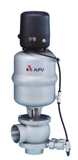
8 -UK3.qxp / Mode of Operation control unit CU41N-S-Direct Connect Double seal valves have been developed for use in the brewing and beverage industries, in dairy and food applications as well as for the chemical and pharmaceutical industries. The field of application of the comprises the safe shut-off of line sections which are separated from one another by two seat seals. A leakage chamber is arranged between the seals, the leakage chamber being forcible closed by the two leakage valves or opened to the atmosphere. Leakage at the seat seals is discharged via the leakage valves to the atmosphere and indicated. actuator - Operation by pneumatic actuator with air connection. The actuator is generally mounted normally closed (NC). - The inner parts of the actuator are maitenance-free. - To avoid pressure hammers, the valve is to be closed against the flow direction of the fluid. yoke - As standard design a control unit DELTA CU41N with NOT element is installed on top of the actuator for the pneumatic control of the valve. The NOT element fulfills the task to increase the closing forces of the closed valve. - The yellow luminous diodes in the control unit indicate the position of the valve shaft. - Observe Service Instructions to ensure safe maintenance of the valve. leakage valve shaft housing 3
. Attention: If the valve is equipped with a valve position indicator or a control unit without NOT element, the max.")


9 -UK3.qxp / Auxiliary Equipment VSM 4.1. Valve position indication A proximity switch holder (PSH) for the valve position indication can be installed on the actuator (fig. 4.1.). Attention: If the valve is equipped with a valve position indicator or a control unit without NOT element, the max. closing pressure reduces (see page 10, max. product pressures). - Proximity switches to signal the limit position of the valve disc can be mounted to the proximity switch holder (PSH) if required. We recommend to use one of our APV standard types: operating distance: 5 mm / diameter: 11 mm. If the operator decides to use valve position indicators other than APV type, we cannot take over any guarantee for a faultless function. - Control Unit The assembly of a control unit on the SD4 valve is possible. The following different designs are available: Direct Connect reference No. Profibus reference No. Device Net reference No. AS - Interface reference No. 1 solenoid valve CU41-S-Direct Connect /93; H CU31 Profibus /93; H CU31 Device Net /93; H CU31 AS-interface /93; H solenoid valve with NOT element (standard) CU41N-S-Direct Connect /93; H CU31N Profibus /93; H CU31N Device Net /93; H CU31N AS-interface /93; H CU3 control unit - For the installation of the control unit on the SD4 valve an adapter is required. Designation: reference number: CU3 - adapter SD4 / SDM /93; H CU4 control unit Designation: reference number: CU4-S-adapter complete /93; H
10 -UK3.qxp / Auxiliary Equipment 4.3 Connections: Beside the housings with weld ends, the following designs are alternatively available: - threaded port according to DIN threaded port IDF / ISS according to ISO threaded port RJT according to BS threaded port SMS - threaded port according to DS flange connection FGN1 DIN - flange connection FGN1 Inch - clamp connection according to DIN clamp connection according to ISO
11 -UK3.qxp / Cleaning For the cleaning of SD4 valves distinction is made between two areas. 5.1 The flow chambers The passages of the valve are cleaned by the cleaning liquid during the cleaning of the connected pipelines. 5.2 The leakage chamber Cleaning of the leakage chamber is undertaken via the leakage valves. The cleaning liquid is supplied via one leakage valve and discharged to the atmosphere via the second leakage valve. The restraint passage of the cleaning liquid provides for a perfect cleaning of the whole leakage chamber. Under normal conditions, 15 valves DN 25/1-100/4 can be cleaned by one spray distribution line DN Cleaning recommendation Recommendation for cleaning times with common operating conditions and CIP liquids. cleaning step pre-flushing caustic flushing 80 C intermediate flushing acid flushing subsequent flushing CIP - spraying cycle 3 x 10 sec. 3 x 10 sec. 2 x 10 sec. 3 x 10 sec. 2 x 10 sec. - Depending on the pressure ratio, cleaning temperatures and degree of soiling, different times have to be adjusted. 5.4 Cleaning of the leakage chamber by the leakage valves - Flushing quantity per CIP spraying cycle about 1,2ltr/10s - Cleaning pressure at CIP cleaning connection min. 2 bar. max. 5 bar. CIP IN CIP OUT G 1/8 6
12 -UK3.qxp / Installation - Installation has to be done in such a way that fluids can drain off the valve housing and is preferably to be realized in vertical position. - The valve housing can be welded direct into the pipeline (compl. dismantable valve insert). - Attention: Observe welding instructions. 6.1 Welding Instructions SD4 - Before welding of the valve, the valve insert must be dismantled from the housing. Careful handling to avoid damage to the parts is necessary. - Welding should only be carried out by certified welders (EN 287-1). (Seam quality EN B ). - The welding of the valve housings must be undertaken in such a way that the valve body is not deformed. - The preparation of the weld seam up to 3 mm thickness must be carried out as a square butt joint without air. (Consider shrinkage!) - TIG orbital welding is best! - After welding of the valve housings or of the mating flanges and after work at the pipelines, the corresponding parts of the installation or pipelines must be cleaned from welding residues and soiling. If these cleaning instructions are not observed, welding residues and dirt particles can settle in the valve and cause damage. - Any damage resulting from the non-observance of these welding instructions is not subject to our guarantee. 7

13 -UK3.qxp / Dimensions / Weights , SD42 mit Control Unit with valve position indication Ø 134 L1 A A housing variants SD41 SD42 Ø Di L Ø K F G ⅛ G F dimensions in mm DN A A1 ø Di F G ø K L L1 weight in kg , , , , , , , , , , ,3 Inch , ,4 1, , , , ,3 2,5 457, , , , , , , , , , , ,3 8

14 -UK3.qxp / Dimensions / Weights 7.2 DELTA SDE43, SDE44 with control unit with valve position indication Ø 134 L1 A housing variants SDE43 SDE44 B H L Ø K A G Ø Di F F dimensions in mm DN A A1 B ø Di F G H ø K L L1 weight in kg , ,5 411,5 5, , ,5 435,5 6, , ,5 490,5 8, , , ,5 523,0 10, , , ,0 598,5 17, , , ,5 637,0 18,9 Inch ,5 22, , ,1 404,1 5,8 1, ,0 34, , ,1 428,9 6, ,4 47, , ,0 486,0 8,8 2,5 457, ,7 60, , ,5 511,1 10, , ,0 72, , ,5 580,9 16, , ,8 97, , ,9 631,4 18,9 9
15 -UK3.qxp / Technical Data 8.1 General terms Product-wetted parts: 316 L, Other parts: Seals: standard: EPDM Option: FPM, VMQ, HNBR Actuator: max. operating temperature: short-term load: 135 C EPDM, HNBR *FPM, *VMQ 140 C EPDM, HNBR *FPM, *VMQ, * no steam CIP-connection for leakage valve: G1/8 air connection (for hose): max. pneumatic air pressure: min. pneumatic air pressure: 6x1mm 8 bar 6 bar Closing times for double seal valves The opening and closing times can be fixed by adjusting the throttle screw at the solenoid valve Specification of compressed air quality compressed air quality: quality class acc. to DIN/ISO content of solid particles: Quality Class3 max. size of solid particles per m³ of 0,5µm <d<1,0 µm 500 of 1,0µm <d<5,0 µm content of water: Quality Class 4 max. dew point temperature + 3 C For installations at lower temperatures or at higher altitudes, additional measures must be considered to reduce the pressure dew point accordingly. content of oil: Quality Class 1 max. 0,01 mg/m³ (The oil applied must be compatible with Polyurethane elastomer materials.) 10
16 -UK3.qxp / Technical Data 8.3 kvs values for SD4 valves in m /h DN SD41, SD42 SDE43, SDE44 SD41, SD42 SDE43, SDE Inch , , max. product pressure in (bar) DN max. line pressure in (bar) valve normally closed without NOT - element or with compressed air failure Inch Ø 74mm actuator Ø 110mm actuator ,4 16,0 40 1,5 3,6 9,6 Ø 165mm actuator ,0 11,2 2,5 4,7 11,6 65 3,5 9,3 3 8,0 80 6, ,4 DN max. product pressures in (bar) valve normally closed with NOT - element max. product pressure limited to 17,6 bar by seal technology Inch Ø 74mm actuator Ø 110mm actuator ,0 16,8 40 1,5 12,4 17,6 Ø 165mm actuator ,6 17,6 2,5 14,0 16, ,5 17,6 3 17, , ,8 11
17 -UK3.qxp / Technical Data 8.5 Valve stroke SD4 dimensions in mm stroke DN stroke Inch , , Pneumatic air consumption at 6 bar control air pressure without NOT- elemet Actuator per stroke NL Ø 74mm 1,0 Ø 110mm 2,1 Ø 165mm 4,5 12
18 -UK3.qxp / Maintenance - The maintenance intervals depend on the corresponding application and should be determined by the operator carrying out temporary checks. - Required tools: - 1x spanner SW13-1x spanner SW17-1x spanner SW19-1x hexagon socket screw key 6 mm - Replacement of seals according to Service Instructions. - Slightly grease all seals before their installation!!!!! - Hint: The seal sets for the old and the new valve design are the same. Recommendation: APV food-grade grease for EPDM, HNBR, FPM (0,75 kg/ tin - ref.-no /93) (60 g/ tube - ref.-no /93) or APV food-grade grease for VMQ (Silicone) (0,6 kg/ tin - ref.-no /93) (60 g/ tube - ref.-no /93)! No matter what type of application, use only those greases being suited for the respective seal material. 9.1 Assembly tool for seat seal (11.1) (Assembly tool to be used for new valve design produced from Nov. 2000, only.) To simplify the installation of the seat seal, the following assembly tools are available. Assembly tool SD4 DN Inch reference number /17; H , /17; H /17; H , /17; H /17; H /17; H /17; H /17; H
19 -UK3.qxp / Service Instructions DELTA SD 41, SD 42, SDE 43, SDE 44 The item numbers refer to the corresponding spare parts lists. DN: RN / Inch: RN Dismantling from the line system 1. Shut off line pressure and discharge lines if possible. 2. Valve design NC (normally closed): Control actuator with air!! Do not touch movable parts! Risk of injury. 3. Remove hexagon screws (4) and lift valve insert including actuator out of the housing (1). 4. Valve design NC (normally closed): Shut off compressed air and detach compressed air supply. The actuator is supplied with compressed air via the NOT element. 5. Design with control unit Detach control unit. housing - Design with valve position indication: Detach proximity switches. Take the indicator housing (proximity switch holder) off the actuator. 14
, while holding up the centering washer (21). Remove the centering washer.")
20 -UK3.qxp / Service Instructions fig indicator housing actuator screw centering washer guide rod actuator Dismantling of wear parts (product-wetted parts) 1. CU design: Unscrew and remove actuator screw. Unscrew hex. screw (22), while holding up the centering washer (21). Remove the centering washer. - Design with valve position indicator: Unscrew and remove actuator screw, while holding up the centering washer (21). Remove the centering washer. (fig ). control unit acutator screw hex. nut. centering washer actuator yoke guide bush housing seal 2. Pull valve shaft (2) with guide rod out of the actuator (18). Remove seat seals (12, 11/11.1).! Valve shaft changed from , see seat seal (fig ) (assembly see ). 3. Unscrew yoke (5) from acutator (18). - The actuator can be maintained (see 11. Service Instructions - Actuator). 4. Remove seat seal (10), shaft seal (9), guide bush (8) and housing seal (3). (assembly see and ) 5. Clean the valve housing, yoke, actuator and shaft with a low solution of a cleaning agent. Never use cleaning agents containing abrasive or polishing particles. shaft seal, seat seal seat seals valve shaft fig valve shaft until valve shaft changed from
21 -UK3.qxp / Service Instructions fig yoke guide bush shaft seal seat seal housing seal Installation of seals and assembly of valve 1. Insert the guide bushes (8) in the yoke (5). Afterwards place the shaft seal (9) and press in the slightly greased seat seal (10) (see fig ) See to the correct direction of installation of the seal. 2. Assemble the yoke (5) on the actuator (18). 3. Insert the two seat seals (11/11.1, 12) in the shaft (2). Slightly grease the seat seals before their installation. During the installation the seal groove should be vented between the seal and the groove wall with a thin object. See to an even fit of the seals. For the modified design of the seat seal 11.1 the assembly tool should be used to install the seal (see pages 13 and 21). 4. Slide the shaft (2) through theyoke (5) and the actuator (18), place the centering washer (20) and fasten the nut (21) until it stops. Hold up the centering washer during this process. Tightening torque: 40 Nm. Fasten the actuator screw. 5. Slightly grease the housing seal (3) and install it in the groove of the yoke flange. 16
. 2.")
22 -UK3.qxp / Service Instructions Installation of the valve insert SD4 1. CU design: Fasten the adapter on the actuator. Place the control unit on the adapter and secure it. - Design with valve position indicator: Fasten the valve position indicator housing (24). 2. For the installation of the valve insert in the design NC (normally closed), observe the following: - Control the actuator (NC design) with pneumatic air min. 6bar. Insert the valve insert carefully into the valve housing. The housing seal (3) must not be damaged during the installation into the housing. Tighten the hex. screws crosswise into the housing flange.! Do not touch movable parts! Risk of injury! Design NC (normally closed) : Shut off air. housing 3. Check the basic adjustment of the valve position indication. - By turning the positioning screw in the control unit, the shift points can be adjusted. fig NO limit position NC proximity switch holder positioning screw - Design with valve position indication: Plug the proximity switches and fasten them. Readjust the proximity switches if necessary. 4. Adjustment of proximity switches (fig. 9.4.) - Place the actuator into one limit position. - Move the corresponding proximity switch into the corresponding position. For this purpose, release the positioning screw and move the holder until the corresponding signal is indicated. Afterwards continue the movement by 2 to 3 mm in order to secure the indication. Fasten the positioning screw. - Place the actuator into the other limit position and carry out the positioning of the second proximity switch. - Upper valve position indication: valve normally open NO - Lower valve position indication: valve normally closed NC 17
23 -UK3.qxp / Service Instructions - Leakage valves 11.1 Maintenance of leakage valves The item numbers refer to the corresponding spare parts list leakage valves SD4 RN: Disconnect the pneumatic air hoses at the two leakage valves. 2. Shut off and discharge the CIP supply line. 3. Remove the CIP supply and discharge lines from the leakage valves. 4. Release the hexagon socket screw and remove the strap. Pull the leakage valves out of the housing flange. 5. Pull out the cap (3), piston (2) and spring (6). 6. Dismantle all seals (5, 7, 8). 7. The assembly is undertaken in reverse order hexagon socket screw spacer support for leakage valves strap 18

24 -UK3.qxp / Service Instructions - Actuator piston rod seal screw v-seal o-ring air connection Maintenance of actuator Spare parts list: SW4 actuator RN: Detach the air hoses from the actuator. 2. Undo the hexagon socket screws from the adapter of the control unit. - Remove the control unit Dismantling of seals 1. Unscrew the two seal screws by means of a spanner SW30, while holding up the actuator with a strap wrench. actuator 2. Remove o-rings and v-seals Installation of seals and assembly of actuator fig v-seal o-ring 1. Install the slightly greased o-rings and v-seals into the seal screws. (fig. 12.3) See to the correct installation position of the v-seal. 2. Slide the seal screws at both sides of the actuator over the piston rod and fasten them. 3. Fasten the adapter for the control unit and the yoke on the actuator. seal screw Attention: Attention: Observe the position of the adapter. During the assembly of the adapter and of the yoke, observe the required valve design NC or NO. NC (FS) = normally closed air-to-raise, spring-to-lower NO (FH) = normally open air-to-lower, spring-to-raise 4. Fasten the air hoses. 19
25 -UK3.qxp / Service Instructions - Actuator At SD4 valves, the size of the actuator can be changed To increase or decrease the actuator sizes ( ø 74 mm, ø 110 mm, ø 165 mm), the corresponding line pressures must be considered, see table page 11. Modification of actuator Dismantling 1. Dismantling of double seal valves is carried out as described in chapter 10 items I. and II. 2. To change the actuator size, the guide rod (6) must be replaced as follows: Clamp the valve seat in a vice. Attention: See to the valve seat not being damaged (use protective jaws or cleaning rags). The slightest damage at the shaft rod can lead to leakages. 3. The guide rod can be turned out of the shaft by means of the centering washer (20) and a spanner SW17. Assembly 1. Turn the corresponding guide rod into the shaft to the actuator. Tightening torque: 40 Nm 2. Further assembly as described in 10, items IV. to VI. 20
26 -UK3.qxp / Assembly Tool Attention! modified from ! By means of the assembly tool only the seat seal (11.1) can be installed. This seat seal must be mounted in the valve shaft, at first Then insert the seat seal (12) in the groove. Press the seal circumferentially into the groove with an assembly tool (screw driver with round edges). After the installation of the seat seal, vent the seal groove between the seal and the groove wall with the assembly tool. See to an even fit of the seal. valve shaft nut thrust ring ring seat seal housing valve shaft threaded bolt The assembly tool consists of: - nut - thrust ring - ring with venting nose - housing - threaded bolt 13.1 Installation of seat seal in valve shaft 1. Insert valve shaft into the housing in such a manner that the seal groove is in the valve housing. 2. Mount the shaft in the housing by means of the threaded bolts. Clamp the housing in the vise. 3. Slightly grease seat seal with APV food-grade grease. Place the seal on the ring with the venting nose until it stops. 4. Insert the ring with the installed seat seal into the housing and press it down until it stops. 5. Introduce the thrust ring into the housing. Screw on the nut and tighten it by a hook spanner until it stops. 6. Release the nut. Pull the ring and thrust ring out of the housing. 7. Take the housing out of the vise, remove the threaded bolts. Take the valve shaft out of the housing. Check the even fit of the seat seal. 21
27 -UK3.qxp / Trouble Shooting Failure Remedy valve is untight, leakages via the leakage valves leakages at the cylinder of the leakage valves Replace the seat seals (12, 12.1, 13). Check the line pressure; perm. line pressure, see chapter 8 Replace the o-rings. (see RN or RN ) Check the cleaning liquid supply. leakage between housing and yoke flange Replace the housing seal (3). air escapes from the actuator (see spare parts list RN: ) Dismantle the actuator (19) from the valve. Replace the v-seal (2) and o-ring (3) in the seal screw (1). actuator does not work, air escapes permanently from the venting plug Replace the actuator. valve position indication is missing or unprecise Carry out fine adjustment according to Service Instructions of the control unit.! If damaged seals are changed, generally all seals should be replaced. For the valve service complete sets of seals are available (see spare parts lists). 15. Spare Parts Lists The reference numbers of the spare parts for the different valve designs and sizes are included in the attached spare parts drawings with corresponding lists. Please indicate the following data to place an order for spare parts: - number of parts required - reference number - designation. subject to change 22
28 BA SD ID: H translation of original manual UK rev. 3 Your local contact: SPX Flow Technology Rosista GmbH Zechenstraße 49 D Unna Phone: +49(0) 23 03/ Fax: +49(0) / For more information about our worldwide locations, approvals, certifications, and local representatives, please visit Copyright 2008 SPX Corporation The information contained in this document, including any specifications and other product details, are subject to change without notice. While we have taken care to ensure the information is accurate at the time of going to press, we assume no responsibility for errors or omissions nor for any damages resulting from the use of the information contained herein.
29
30
31
32
33
34
35
36
37
38
39
40
41
42
43
DELTA PR2. Operating Manual. Sampling Valve. Read and understand this manual prior to operating or servicing this product.
 Operating Manual DELTA PR2 Sampling Valve Read and understand this manual prior to operating or servicing this product. UK Declaration of Conformity for Valves and Valve Manifolds SPX Flow Technology
DELTA DKRH2. Operating Manual. -High Pressure Designwww.sks-online.com. Double Seat Ball Valve with Cleaning Connection
 Operating Manual DELTA DKRH2 Read and understand this manual prior to operating or servicing this product. Double Seat Ball Valve with Cleaning Connection - Declaration of Conformity for Valves and Valve
DELTA DKR2. Operating Manual. Double - Seat Ball valve with Cleaning Connection
 Operating Manual DELTA DKR2 Double - Seat Ball valve with Cleaning Connection Read and understand this manual prior to operating or servicing this product. www.sks-online.com UK Declaration of Conformity
DSV. Operating Manual. Double Seal Butterfly Valve. Read and understand this manual prior to operating or servicing this product.
 Operating Manual DSV Double Seal Butterfly Valve Read and understand this manual prior to operating or servicing this product. www.sks-online.com UK DSV-UK2.qxp / 10.2005 Table of Contents: Page: 1.
DELTA SVS1F. Operating Manual. Butterfly Valve. Read and understand this manual prior to operating or servicing this product.
 Operating Manual DELTA SVS1F Butterfly Valve Read and understand this manual prior to operating or servicing this product. www.sks-online.com UK Declaration of Conformity for Valves and Valve Manifolds
DELTA RUF3. Operating Manual. Non - return Valve. Read and understand this manual prior to operating or servicing this product.
 Operating Manual DELTA RUF3 Non - return Valve Read and understand this manual prior to operating or servicing this product. www.sks-online.com UK Table of contents Page 1. General Terms 2 2. Safety
APV DELTA SDMS4 DN ,1-4 DOUBLE SEAL VALVE MIT DIAPHRAGM AND FAN SUPPORT
 INSTRUCTION MANUAL APV DELTA SDMS4 DN 25-00, -4 DOUBLE SEAL VALVE MIT DIAPHRAGM AND FAN SUPPORT SAFETY AGAINST EXPLOSION - FOR SPECIFIC ATEX-APPLICATIONS FORM NO.: H336443 REVISION: UK-0-ATEX READ AND
DELTA SW4 Single Seat and Change-over Valve
 Operating Manual Read and understand this manual prior to operating or servicing this product. - UK-3.qxp 23.04.2009 Table of Contents Page. General Terms 2 2. Safety Instructions 2 3. Mode of Operation
APV DELTA PR2 INSTRUCTION MANUAL SAMPLING VALVE
 INSTRUCTION MANUAL APV DELTA PR2 SAMPLING VALVE FORM NO.: H70787 REVISION: UK-4 READ AND UNDERSTAND THIS MANUAL PRIOR TO OPERATING OR SERVICING THIS PRODUCT. UK EU Declaration of Conformity for Valves
DELTA DE3. INSTRUCTION MANUAL DOUBLE SEAT VALVE
 INSTRUCTION MANUAL DELTA DE3 DOUBLE SEAT VALVE FORM NO.: 170731 REVISION: UK-7 READ AND UNDERSTAND THIS MANUAL PRIOR TO OPERATING OR SERVICING THIS PRODUCT. UK Declaration of Conformity for Valves and
DELTA SD4. double seal valves
 PV VVES DET SD4 double seal valves SPX is highly coitted to delivering sustainable solutions, which exceed customer expectations in value and return through a focus on. Waste prevention and loss reduction
APV DELTA SWmini4 INSTRUCTION MANUAL SINGLE SEAT VALVE DN 10, 15, 20
 INSTRUCTION MANUAL APV DELTA SWmini4 SINGLE SEAT VALVE DN 0, 5, 0 FORM NO.: 07909 REVISION: - READ AND UNDERSTAND THIS MANUAL PRIOR TO OPERATING OR SERVICING THIS PRODUCT. Declaration of Conformity for
Operating Instruction:
 Operating Instruction: Leakage - Butterfly valve with manual operation Types LSV 4365 LSV 4366 LSV 4367 LSV 4368 LSV 4369 LSV 4370 Kieselmann GmbH Paul-Kieselmann-Str. 4-10 75438 Knittlingen Telefon +49
DELTA SWcip4.
 APV valves DELTA SWcip4 Double Seal Valve SPX is highly committed to delivering sustainable solutions, which exceed customer expectations in value and return through a focus on. Waste prevention and loss
APV DELTA SWS4 INSTRUCTION MANUAL DIVERT VALVE
 INSTRUCTION MANUAL APV DELTA SWS4 DIVERT VALVE FORM NO.: H322956 REVISION: - READ AND UNDERSTAND THIS MANUAL PRIOR TO OPERATING OR SERVICING THIS PRODUCT. Declaration of Conformity for Valves and Valve
APV DELTA KHV INSTRUCTION MANUAL BALL VALVE
 INSTRUCTION MANUAL APV DELTA KHV BALL VALVE FORM NO.: H7076 REVISION: UK-2 READ AND UNDERSTAND THIS MANUAL PRIOR TO OPERATING OR SERVICING THIS PRODUCT. UK Declaration of Conformity for Valves and Valve
ApV VAlVe s As e pti c s i n g le s eat VAlVe
 DELTA MS4/MSP4 Aseptic Single Seat Valve APV valves SPX is highly coitted to delivering sustainable solutions, which exceed customer expectations in value and return through a focus on. Waste prevention
APV DELTA SD4 DN25-100, 1-4 DOUBLE SEAL VALVE
 INSTRUCTION MANUAL APV DELTA SD4 DN25-00, -4 DOUBLE SEAL VALVE SAFETY AGAINST EXPLOSION - FOR SPECIFIC ATEX-APPLICATIONS FORM NO.: H33026 REVISION: -0-ATEX READ AND UNDERSTAND THIS MANUAL PRIOR TO OPERATING
Operating Instructions Ball Valves
 Armaturen GmbH Armaturen, Rohre, Sonderteile aus Edelstahl Fittings, pipes, special parts of stainless steel Operating Instructions KV-SS KV-ZF M & S Armaturen GmbH Carl Benz Str.2 D-75057 Kürnbach Germany
Valve Key BUTTERFLY, SINGLE SEAT, MIX PROOF, ASEPTIC, REGULATING, PROCESS VALVES
 Valve Key BUTTERFLY, SINGLE SEAT, MIX PROOF, ASEPTIC, REGULATING, PROCESS VALVES TABLE OF CONTENTS SV & SVS Butterfly Valves...3-4 SW Series Single Seat Valves...5-6 SWmini Series Fractional Size Single
Valve Key BUTTERFLY, SINGLE SEAT, MIX PROOF, ASEPTIC, REGULATING, PROCESS VALVES
 Valve Key BUTTERFLY, SINGLE SEAT, MIX PROOF, ASEPTIC, REGULATING, PROCESS VALVES TABLE OF CONTENTS SV & SVS Butterfly Valves...3-4 SW Series Single Seat Valves...5-6 SWmini Series Fractional Size Single
APV DELTA SDMS4 INSTRUCTION MANUAL DOUBLE SEAL VALVE WITH DIAPHRAGM AND FAN SUPPORT
 INSTRUCTION MANUAL APV DOUBLE SEAL VALVE WITH DIAPHRAGM AND FAN SUPPORT FORM NO.: H329486 REVISION: -0 READ AND UNDERSTAND THIS MANUAL PRIOR TO OPERATING OR SERVICING THIS PRODUCT. EU Declaration of Conformity
Mounting and Operating Instructions EB 8048 EN. Type and Type Pneumatic Control Valves Type 3249 Aseptic Angle Valve
 Type 3249-1 and Type 3249-7 Pneumatic Control Valves Type 3249 Aseptic Angle Valve Ball body version Special version with packing Type 3249-7 Control Valve with Type 3277 Actuator and integrated positioner
APV DELTA SVS1F DN25-100, 1-4 BUTTERFLY VALVE
 INSTRUCTION MANUAL APV DELTA SVSF DN5-00, -4 BUTTERFLY VALVE SAFETY AGAINST EXPLOSION - FOR SPECIFIC ATEX-APPLICATIONS FORM NO.: H33057 REVISION: UK-0-ATEX READ AND UNDERSTAND THIS MANUAL PRIOR TO OPERATING
Unique 7000 Series Valve - Standard and Reverse Acting
 Instruction Manual Unique 7000 Series Valve - Standard and Reverse Acting ESE00213-ENUS4 2012-01 Original manual Table of contents The information herein is correct at the time of issue but may be subject
Mounting and Operating Instructions EB 8053 EN. Series 250 Type and Type Pneumatic Control Valves
 Series 250 Type 3252 1 and Type 3252 7 Pneumatic Control Valves Type 3252 High-pressure valve with Type 3277 Pneumatic Actuator and Type 3767 Electropneumatic Positioner Mounting and Operating Instructions
APV DELTA UF3(A) / UFR3(A) DN25-100,1-4 RELIEF VALVE
 / UFR3(A) DN25-100,1-4 RELIEF VALVE") INSTRUCTION MANUAL APV DELTA UF3(A) / UFR3(A) DN25-00, -4 RELIEF VALVE SAFETY AGAINST EXPLOSION - FOR SPECIFIC ATEX-APPLICATIONS FORM NO.: H332844 REVISION: UK-0-ATEX READ AND UNDERSTAND THIS MANUAL PRIOR
INSTRUCTION MANUAL APV DELTA UF3(A) / UFR3(A) DN25-00, -4 RELIEF VALVE SAFETY AGAINST EXPLOSION - FOR SPECIFIC ATEX-APPLICATIONS FORM NO.: H332844 REVISION: UK-0-ATEX READ AND UNDERSTAND THIS MANUAL PRIOR
APV DELTA UF3(A) / UFR3(A)
 / UFR3(A)") INSTRUCTION MANUAL APV DELTA UF3(A) / UFR3(A) RELIEF VALVE FORM NO.: 70784 REVISION: UK-7 READ AND UNDERSTAND THIS MANUAL PRIOR TO OPERATING OR SERVICING THIS PRODUCT. UK EU Declaration of Conformity
INSTRUCTION MANUAL APV DELTA UF3(A) / UFR3(A) RELIEF VALVE FORM NO.: 70784 REVISION: UK-7 READ AND UNDERSTAND THIS MANUAL PRIOR TO OPERATING OR SERVICING THIS PRODUCT. UK EU Declaration of Conformity
DPX - DPAX butterfly valve technical description
 DPX - DPAX butterfly valve technical description DEFINOX butterfly valves have been made for several years using a choice of materials and machining conditions that guarantee top quality strength and surface
Operating instruction
 Translation of the original Operating instruction Butterfly valve P D F a k 1 6 / 0 2 / 2 0 1 8 ENGLISH EN K I E S E L M A N N G m b H Paul-Kieselmann-Str. 4-10 75438 Knittlingen ( +49(0) 7043 371-0 7
Armaturenwerk Hötensleben GmbH. Valve Technology. A member of NEUMO Ehrenberg Group. Edition 3.0
 Armaturenwerk Hötensleben GmbH Valve Technology A member of NEUMO Ehrenberg Group Edition 3.0 Proven Valves for all Purpose ATEX Directive 2014/34/EU Armaturenwerk Hötensleben GmbH is using the revised
Operating instructions - Translation of the original -
 Operating instructions - Translation of the original - Single seat valve Two-way-valve Type: 5714 pneumatic operation KIESELMANN GmbH Paul-Kieselmann-Str.4-10 D - 75438 Knittlingen +49 (0) 7043 371-0 Fax:
Mounting and Operating Instructions EB 8135/8136 EN. Series V2001 Valves Type 3535 Three-way Valve for Heat Transfer Oil
 Series V2001 Valves Type 3535 Three-way Valve for Heat Transfer Oil Type 3535 Three-way Valve with bellows seal and rod-type yoke (partial view) Mounting and Operating Instructions EB 8135/8136 EN Edition
Operating instructions - Translation of the original -
 Operating instructions - Translation of the original - KIESELMANN GmbH Paul-Kieselmann-Str.4-10 D - 75438 Knittlingen +49 (0) 7043 371-0 Fax: +49 (0) 7043 371-125 www.kieselmann.de sales@kieselmann.de
Mounting and Operating Instructions EB 8222 EN. Type 3310/AT and Type 3310/3278 Pneumatic Control Valves. Type 3310 Segmented Ball Valve
 Type 3310/AT and Type 3310/3278 Pneumatic Control Valves Type 3310 Segmented Ball Valve Fig. 1 Type 3310/3278 with positioner Fig. 2 Type 3310/AT Mounting and Operating Instructions EB 8222 EN Edition
Mounting and Operating Instructions EB 8111/8112 EN. Series V2001 Valves Type 3321 Globe Valve
 Series V2001 Valves Type 3321 Globe Valve Type 3321 Globe Valve with rod-type yoke and Type 3372 Electropneumatic Actuator (350 cm²) Mounting and Operating Instructions EB 8111/8112 EN Edition June 2013
Mounting and Operating Instructions EB 5868/5869 EN
 Electric Control Valves Types 3213/5857, 3213/5824, Types 3214/5824, 3214/3374, 3214/3274 with safety function: Types 3213/5825, 3214/5825, 3214/3374, 3214/3274 Pneumatic Control Valves Types 3213/2780-1,
T-smart Butterfly Valves. Made by GEA Tuchenhagen. GEA Mechanical Equipment / GEA Tuchenhagen
 Liquids to Value T-smart Butterfly Valves Made by GEA Mechanical Equipment / T-smart Butterfly Valves For many years, butterfly valves have proven their worth in process plants with different types of
APV DELTA AP1/APT1 INSTRUCTION MANUAL ASEPTIC PROCESS VALVE
 INSTRUCTION MANUAL APV DELTA AP/APT ASEPTIC PROCESS VALVE FORM NO.: H3755 REVISION: UK- READ AND UNDERSTAND THIS MANUAL PRIOR TO OPERATING OR SERVICING THIS PRODUCT. UK EU Declaration of Conformity for
Pressure relief valve
 Pressure relief valve Operating manual Series DHV 712 Version BA-2015.10.20 EN Print-No. 300 510 TR MA DE Rev001 ASV Stübbe GmbH & Co. KG Hollwieser Straße 5 32602 Vlotho Germany Phone: +49 (0) 5733-799-0
Operating instruction. Butterfly valve. Translation of the original ENGLISH
 Translation of the original Operating instruction Butterfly valve P D F a k 0 4 / 0 2 / 2 0 1 9 ENGLISH GB K I E S E L M A N N G m b H Paul-Kieselmann-Str. 4-10 75438 Knittlingen ( +49(0) 7043 371-0 7
Operating instructions - Translation of the original -
 Operating instructions - Translation of the original - Single seat valve pneumatic operation KIESELMANN GmbH Paul-Kieselmann-Str.4-10 D - 75438 Knittlingen +49 (0) 7043 371-0 Fax: +49 (0) 7043 371-125
Angle seat valve with piston actuator VZXA-...-K
 Angle seat valve with piston actuator VZXA-...-K Festo AG & Co. KG Postfach 73726 Esslingen Germany +49 711 347-0 www.festo.com 3 Further information Accessories www.festo.com/catalogue Spare parts www.festo.com/spareparts
BR 31a Rack-and-pinion Actuator,
 Operating, assembly and maintenance instructions BR 31a Rack-and-pinion Actuator, SRP and DAP 1. General These instructions are intended to support the user in the assembly, maintenance, and repair of
Mounting and Operating Instructions EB 8097 EN. Pneumatic Control Valves Type and Type
 Pneumatic Control Valves Type 3347-1 and Type 3347-7 Hollow-mold cast body with welding ends Full-mold cast body with threaded connections Fig. 1 Type 3347-7 Control Valve with Type 3277 Actuator and integral
Mounting and Operating Instructions EB 8039 EN. Type 3351 Pneumatic On/off Valve. Type 3351 Pneumatic On/off Valve. Type 3351 Pneumatic On/off Valve
 Type 3351 Pneumatic On/off Valve Type 3351 Pneumatic On/off Valve Type 3351 Pneumatic On/off Valve Version with handwheel Mounting and Operating Instructions EB 8039 EN Edition May 2016 Definition of signal
Valve Technology DIN EN Butterfly Valves
 Armaturenwerk Hötensleben GmbH Valve Technology DIN EN 14432 Butterfly Valves A member of NEUMO Ehrenberg Group Edition 3.0 Proven Valves for all Purpose ATEX Directive 2014/34/EU Armaturenwerk Hötensleben
APV DELTA SVS1F INSTRUCTION MANUAL BUTTERFLY VALVE. Scan for SV1/SVS1F Valve Maintenance Video
 INSTRUCTION MANUAL APV DELTA SVSF BUTTERFLY VALVE FORM NO.: H74933 REVISION: UK-8 READ AND UNDERSTAND THIS MANUAL PRIOR TO OPERATING OR SERVICING THIS PRODUCT. Scan for SV/SVSF Valve Maintenance Video
BIOVENT. Hygienic Valve
 BIOVENT BIOVENT Committed to perfection in every detail Powerful valve actuator BIOVENT control valves are usually combined with pneumatic multi-spring ARCAPAQ actuator type 813. Not only is it cost effective,
Angle seat valve with piston actuator VZXA-...-K
 Angle seat valve with piston actuator VZXA-...-K Instructions Operating (Translation of the original instructions) Festo AG & Co. KG Ruiter Straße 82 73734 Esslingen Germany +49 711 347-0 www.festo.com
Instruction Manual. Unique Single Seat Valve - Manually Operated ESE00523-EN Original manual TD TD
 Instruction Manual Unique Single Seat Valve - Manually Operated TD 461-583 TD 461-791 ESE00523-EN6 2016-07 Original manual Table of contents The information herein is correct at the time of issue but
Instruction Manual. Alfa Laval Safety Valve ESE03058-EN Original manual
 Instruction Manual Alfa Laval Safety Valve 2001-0000 ESE03058-EN1 2015-11 Original manual Table of contents The information herein is correct at the time of issue but may be subject to change without
back to main page Type: Butterfly valves Instructions and Operation Manual Warning! Warning! Danger for life! 1. Intended use Danger for life!
 Instructions and operation manual for butterfly valves This manual is intended to support the users of Herberholz butterfly valves type HRD/HRA, RD/RA, LDKE/LDKF for installation, operation and maintenance
Operating instructions - Translation of the original -
 Operating instructions - Translation of the original - Ball-type check valve Type: 5080 KIESELMANN GmbH Paul-Kieselmann-Str.4-10 D - 75438 Knittlingen +49 (0) 7043 371-0 Fax: +49 (0) 7043 371-125 www.kieselmann.de
Instruction Manual. Unique Single Seat Valve - Long Stroke ESE00222-EN
 Instruction Manual Unique Single Seat Valve - Long Stroke ESE00222-EN4 2014-12 Original manual Table of contents The information herein is correct at the time of issue but may be subject to change without
APV DELTA SVS1F DN
 INSTRUCTION MANUAL APV DELTA SVSF DN 25-250 BUTTERFLY VALVE FORM NO.: H20570 REVISION: UK-5 READ AND UNDERSTAND THIS MANUAL PRIOR TO OPERATING OR SERVICING THIS PRODUCT. Scan for SV/SVSF Valve Maintenance
Instruction Manual. Unique RV-ST Regulating Valve ESE02127-EN Original manual
 Instruction Manual Unique RV-ST Regulating Valve 2404-0022 ESE02127-EN1 2012-06 Original manual Table of contents The information herein is correct at the time of issue but may be subject to change without
Operating Instructions Garlock Butterfly Valves DN : mm / 2-24
 Operating Instructions Garlock Butterfly Valves DN : 50-600 mm / 2-24 PN : 10 / 16 Type: GAR-SEAL SAFETY-SEAL STERILE-SEAL MOBILE-SEAL Conformity declaration... 14 0 Introduction... 15 1 Proper use...
APV DELTA DA3+ INSTRUCTION MANUAL DOUBLE SEAT MIXPROOF VALVE. Scan for DA3+ Valve Maintenance Video
 INSTRUCTION MANUAL APV DELTA DA3+ DOUBLE SEAT MIXPROOF VALVE FORM NO.: H7958 REVISION: UK-5 READ AND UNDERSTAND THIS MANUAL PRIOR TO OPERATING OR SERVICING THIS PRODUCT. Scan for DA3+ Valve Maintenance
Storage, operating and maintenance instructions for AZ plug valves and Standard valves
 ARMATUREN Plug - Valves metallic with PTFE Sleeve 2-7 way Storage, operating and maintenance instructions for AZ plug valves and Standard valves Plug - Valves FEP/PFA - lined, 2-3 way Butterfly - Valves
ORIGA SYSTEM PLUS Guides, Brakes and Valves for Modular Linear Drive Systems OSP Appendix to the Operating Instructions
 ORIGA SYSTEM PLUS Guides, Brakes and Valves for Modular Linear Drive Systems OSP Appendix to the Operating Instructions TAll personnel who have anything to do with the OSP fitted with guides, brakes or
Installation and Operating Instructions for EAS -NC clutch Type 45_. _. _ Sizes 02 and 03
 Table of contents: Please read and observe this Operating Instruction carefully! A possible malfunction or failure of the clutch and any damage may be caused by not observing it. Page 1: - Table of contents
MSC Manifolds - DIN for Steam Distribution and Condensate Collection Installation and Maintenance Instructions
 1170650/3 IM-P117-17 ST Issue 3 MSC Manifolds - DIN for Steam Distribution and Condensate Collection Installation and Maintenance Instructions 1 General safety information 2 General product information
Instruction Manual. Alfa Laval Safety Valve ESE03058-EN Original manual
 Instruction Manual Alfa Laval Safety Valve 2001-0000 ESE03058-EN3 2016-08 Original manual Table of contents The information herein is correct at the time of issue but may be subject to change without
Angle seat valve with diaphragm actuator VZXA-...-M
 Angle seat valve with diaphragm actuator VZXA-...-M Instructions Operating (Translation of the original instructions) Festo AG & Co. KG Ruiter Straße 82 73734 Esslingen Germany +49 711 347-0 www.festo.com
Installation and Operating Instructions
 Original Installation and Operating Instructions Hawle E2 Valve with Flange Outlet, System 2000 or PE Spigot Ends Table of Contents A) General...... 2 A1 Symbols..... 2 A2 Intended use... 2 A3 Labeling...
Type Operating Instructions. Bedienungsanleitung Manuel d utilisation
 Globe control valve, pneumatically operated Actuator sizes 40 mm - 125 mm, Nominal diameter DN10-65 Kolbengesteuertes Geradsitzventil Antriebsgrößen 40 mm - 125 mm, Nennweiten DN10-65 Vanne à siège droit
series BUTTERFLY VALVE DOUBLE ECCENTRIC FLANGED FAF 3800 PRODUCTION STANDARDS DN100 DN2000 PN Design EN 593 EN ISO Flanged
 PRODUCTION STANDARDS DN100 DN2000 PN 10-16-25 Design EN 593 Connection End Connection EN 1092-2 ISO 7005-2 - Flanged EN 558 Series 14 DIN 3202 F4 Marking EN 19 Tests EN 12266-1 Corrosion Protection Electrostatic
Instruction Manual. Unique Single Seat Valve - Manually Operated ESE00523-EN Original manual TD TD
 Instruction Manual Unique Single Seat Valve - Manually Operated TD 461-583 TD 461-791 ESE00523-EN2 2010-02 Original manual Table of contents The information herein is correct at the time of issue but
Instruction Manual. Unique 7000 Series - Long Stroke ESE00220-ENUS Original manual
 Instruction Manual Unique 7000 Series - Long Stroke ESE00220-ENUS4 2014-12 Original manual Table of contents The information herein is correct at the time of issue but may be subject to change without
APV DELTA DE3 INSTRUCTION MANUAL DOUBLE SEAT VALVE. Scan for DE3 Valve Maintenance Video
 INSTRUCTION MANUAL APV DELTA DE3 DOUBLE SEAT VALVE FORM NO.: 7073 REVISION: UK-7 READ AND UNDERSTAND THIS MANUAL PRIOR TO OPERATING OR SERVICING THIS PRODUCT. Scan for DE3 Valve Maintenance Video UK EU
Instruction Manual. Unique RV-P, pneumatic regulating valve ESE02801-EN Original manual
 Instruction Manual Unique RV-P, pneumatic regulating valve 2405-0001 ESE02801-EN2 2016-10 Original manual Table of contents The information herein is correct at the time of issue but may be subject to
Instruction Manual. Unique 7000 Series Aseptic - Manually Operated ESE02421-ENUS Original manual
 Instruction Manual Unique 7000 Series Aseptic - Manually Operated 2210-0042 ESE02421-ENUS1 2013-03 Original manual Table of contents The information herein is correct at the time of issue but may be subject
Mounting and operating instructions EB 8093 EN. Series 240 Pneumatic Control Valve for Cryogenic Temperatures. Type and
 Series 240 Pneumatic Control Valve for Cryogenic Temperatures Type 3248-1 and 3248-7 Fig. 1 Type 3248 Cryogenic Valve with Type 3277 Pneumatic Actuator as globe and angle valve Mounting and operating instructions
MAINTENANCE NOTICE MANUAL AND AUTOMATIC INTERFLANGE BUTTERFLY VALVES
 MANUAL AND AUTOMATIC INTERFLANGE BUTTERFLY VALVES www.definox.com IT-TDFX-222 Revision 0 Page 1/16 October 2008 TABLE OF CONTENTS CHANGE MANAGEMENT 3 SAFETY 4 1.1 IMPORTANT INFORMATION: 4 1.2 GENERAL INFORMATION:
DELTA SD4 DOUBLE SEAL VALVES
 DET SD4 DOUBE SE VVES SPX is highly committed to delivering sustainable solutions, which exceed customer expectations in value and return through a focus on. Waste prevention and loss reduction Reuse of
Mounting and Operating Instructions EB 8097 EN. Type and Type Pneumatic Control Valves
 Type 3347-1 and Type 3347-7 Pneumatic Control Valves Type 3347-7, cast body with welding ends Type 3347-7, bar stock body with threaded connections Mounting and Operating Instructions EB 8097 EN Edition
Series 240 Type and Type Pneumatic Control Valves Type 3347 Hygienic Angle Valve
 Series 240 Type 3347-1 and Type 3347-7 Pneumatic Control Valves Type 3347 Hygienic Angle Valve Application Control valve for hygienic applications in the food and pharmaceutical industries Valve size DN
Series 250 Pneumatic Control Valves Type and
 Series 250 Pneumatic Control Valves Type 3252-1 and 3252-7 Fig. 1 Type 3252 High-pressure Valve with Type 3277 Pneumatic Actuator and Type 3767 i/p Positioner Edition November 1998 Mounting and operating
Globe Control Valve Series 1a
 Maintenance Globe Control Valve Series 1a are subject to alteration without notice. The text and illustrations do not necessarily display the scope of supply or any ordering of spare parts. Drawings and
Condensate Drain Valve AK 45. Original Installation Instructions English
 Condensate Drain Valve AK 45 EN English Original Installation Instructions 810467-03 1 Contents Important Notes Page Usage for the intended purpose...4 Safety note...4 Danger...4 Attention...4 PED (Pressure
BUTTERFLY VALVE 27 SERIES Pneumatic actuator - El-O-Matic
 C D E FIGURE: PD: pneumatic actuator, double acting PE: pneumatic actuator, spring return PEO: pneumatic actuator, spring return, normally open BUTTERFLY VALVE 27 SERIES Pneumatic actuator - El-O-Matic
Instruction Manual. SBV Sanitary Ball Valve ESE01782-EN Original manual TD
 Instruction Manual SBV Sanitary Ball Valve TD 451-013 ESE01782-EN7 2016-10 Original manual Table of contents The information herein is correct at the time of issue but may be subject to change without
Diaphragm seal with sterile connection For sanitary applications Models , , and , threaded connection
 Diaphragm seals Diaphragm seal with sterile connection For sanitary applications Models 990.18, 990.19, 990.20 and 990.21, threaded connection WIKA data sheet DS 99.40 for further approvals see page 3
Instruction Manual. Unique Single Seat Valve - Tank Outlet ESE00364-EN Original manual TD _2
 Instruction Manual Unique Single Seat Valve - Tank Outlet TD 461-494_2 ESE00364-EN5 2011-05 Original manual Table of contents The information herein is correct at the time of issue but may be subject
Diaphragm Valve, Metal
 Diaphragm Valve, Metal Construction The GEMÜ pneumatically operated 2/2-way diaphragm valve has a low maintenance piston actuator which can be controlled by inert gases. The valve has an integrated optical
Compensation unit AGE-XY 50-80
 Translation of the origninal manual Compensation unit AGE-XY 50-80 Assembly and operating manual Superior Clamping and Gripping Imprint Imprint Copyright: This manual remains the copyrighted property of
Mounting and Operating Instructions EB 8227 EN. Pneumatic Control Valve Type 3331/BR 31a Special version Type 3331/3278. Type 3331 Butterfly Valve
 Pneumatic Control Valve Type 3331/BR 31a Special version Type 3331/3278 Type 3331 Butterfly Valve Fig. 1 Type 3331/BR 31a (below) and Type 3331/3278 (top) Mounting and Operating Instructions EB 8227 EN
Mounting and Operating Instructions EB 8111/8112 EN. Valve Series V2001 Globe Valve Type 3321
 Valve Series V2001 Globe Valve Type 3321 Fig. 1 Type 3321 Valve with mounted rod-type yoke for pneumatic or electric actuators (partial view) Mounting and Operating Instructions EB 8111/8112 EN Edition
BAA S370 Select. SVP valve (Right angle, double right angle, cross, angular seat variant) DN , DN 1 4
 DN , DN 1 4") BAA S370 Select SVP valve (Right angle, double right angle, cross, angular seat variant) Manually and pneum. operated Änderung Datum Name Änderung Datum Name Änderung Datum Name Änderung Datum Name erst.
BAA S370 Select SVP valve (Right angle, double right angle, cross, angular seat variant) Manually and pneum. operated Änderung Datum Name Änderung Datum Name Änderung Datum Name Änderung Datum Name erst.
Type Operating Instructions. Bedienungsanleitung Manuel d utilisation. 2/2-way solenoid valve 2/2-Wege-Magnetventil Électrovanne 2/2 voies
 Type 5404 2/2-way solenoid valve 2/2-Wege-Magnetventil Électrovanne 2/2 voies Operating Instructions Bedienungsanleitung Manuel d utilisation Contents 1 Operating instructions...2 2 Intended use...3 3
IMOI 2010 Rev 0
 FOREWORD The following instructions are offered as a reference aid to the valve user when installing, maintaining or operating Williams Gate, Globe and Swing Check valves. This document, consisting of
Globe Valve Type Fig. 1 Type 3241 Globe Valve. Mounting and Operating Instructions EB EN
 Globe Valve Type 3241 Fig. 1 Type 3241 Globe Valve Mounting and Operating Instructions EB 8015-1 EN Edition July 2012 Contents Contents Page 1 Design and principle of operation.................... 4 2
Operation Manual For KITZ B Series Pneumatic Valve Actuators
 Operation Manual For KITZ B Series Pneumatic Valve Actuators Thank you for choosing KITZ products. For safe and trouble-free function and performance of the product, ensure to read and understand all items
Operating Instructions ROCO Butterfly Valve with SKG Slider-crank Mechanism, with Electric Multi-turn Actuator
 Operating Instructions ROCO Butterfly Valve with SKG Slider-crank Mechanism, with Electric Multi-turn Actuator 1 Product and Performance Description 2 Design Features of ROCO Butterfly Valve 3 Installation
OPW Emergency Safety Disconnector. Safety Breakaway Coupling Type NTS-PU Series (Pull-Away) Sizes 1-4 (DN25 DN100) Page 1
 Sizes 1-4 (DN25 DN100) Page 1") OPW Emergency Safety Disconnector Safety Breakaway Coupling Type NTS-PU Series (Pull-Away) Sizes 1-4 (DN25 DN100) Page 1 Content Please read carefully the following OPW user manual to avoid incidents and
OPW Emergency Safety Disconnector Safety Breakaway Coupling Type NTS-PU Series (Pull-Away) Sizes 1-4 (DN25 DN100) Page 1 Content Please read carefully the following OPW user manual to avoid incidents and
In combination with an actuator, e.g. a SAMSON Type 3271 or Type 3277 Pneumatic Actuator
 Type 3510 Micro-flow Valve In combination with an actuator, e.g. a SAMSON Type 3271 or Type 3277 Pneumatic Actuator DIN version Translation of original instructions Type 3510-1 (left) and Type 3510-7 (right)
BUTTERFLY VALVE WITH WELDED ENDS INSTALLATION AND MAINTENANCE MANUAL
 BUTTERFLY VALVE 31300 SERIES INSTRUCTIONS FOR INSTALLATION, USE AND MAINTENANCE 1. Overview Read these instructions carefully before starting the valve installation and start-up work. Safe keep the instructions
INSTALLATION, SERVICE AND MAINTENANCE INSTRUCTIONS Y-FILTER 83700
 INSTALLATION, SERVICE AND MAINTENANCE INSTRUCTIONS Y-FILTER 83700 11.106.32.0001 INOXPA, S.A. c/telers, 54 Aptdo. 174 E-17820 Banyoles Girona (Spain) Tel. : (34) 972-57 52 00 Fax. : (34) 972-57 55 02 email:
INSTALLATION, SERVICE AND MAINTENANCE INSTRUCTIONS Y-FILTER 83700
 INSTALLATION, SERVICE AND MAINTENANCE INSTRUCTIONS Y-FILTER 83700 11.106.32.0001 INOXPA, S.A. c/telers, 54 Aptdo. 174 E-17820 Banyoles Girona (Spain) Tel. : (34) 972-57 52 00 Fax. : (34) 972-57 55 02 email: