Layer Rated Line Pull Wire Rope Capacity lb. (1134 kg.) 6 (1.8m)
|
|
|
- Leslie Stone
- 6 years ago
- Views:
Transcription
1
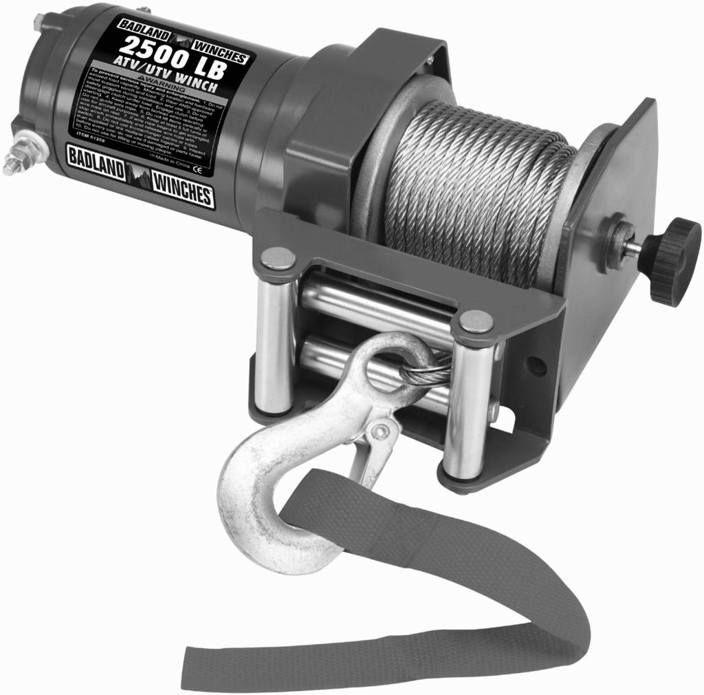
2 Specifications Rated Single 2,500 lb. (1,134 kg.) Line Pull Application Utility/Shop/ATV Motor 12V DC 1 HP Permanent Magnet Power IN & Power OUT Yes Duty Cycle Rating 5% (45 sec at Max Rated Load; 14 min, 15 sec Rest) Geartrain Single-stage Planetary Gear Ratio 153:1 Freespool Yes Brake Auto. Load Holding Dynamic Drum (Dia. X L) 1.25 X 2.8 (32mm X 71mm) Hook 1/4 Eye Hook Fairlead Roller with nylon bushings Wire Rope Size / Type Battery Battery Cables Mounting Pattern Mounting Hardware Overload Protection Sound Rating Overall Dimensions (L X D X H) Weight IP Rating Winch Certification Ø5/32 x 50 (Ø4mm X 15.2m) Nominal strength=2,800 lb 7X19 Galvanized Steel Aircraft Wire Rope 12VDC, Minimum 12 Ah 10 gauge, 5.8 (1.78m) long 3.15 (80mm) Winch: 2x G8, M X 35mm Fairlead: 2x G8, M X 19mm In line Circuit Breaker 85 db X 3.88 X 4.25 (286 X 99 X 108mm) 14.7 lb. (6.7 kg.) IP 65 - Winch and Controls (resistant to water jets) CE Layer Rated Line Pull Wire Rope Capacity lb. (1134 kg.) 6 (1.8m) lb. (928 kg.) 13.3 (4.0m) lb. (785 kg.) 21.9 (6.7m) lb. (680 kg.) 31.8 (9.7m) lb. (600 kg.) 43.1 (13.1m) lb. (537 kg.) 50 (15.2m) First Layer of Wire Rope Performance Line Pull lb. (kg.) Line Speed fpm (mpm) Amp Draw (@ 12V) 1 0 (0) 13.3 (4.1) (454) 8.3 (2.5) (907) 4.1 (1.2) (1134) 2.7 (0.8) 132 Page 2 For technical questions, please call Item 61840
3 WARNING SYMBOLS AND DEFINITIONS This is the safety alert symbol. It is used to alert you to potential personal injury hazards. Obey all safety messages that follow this symbol to avoid possible injury or death. Indicates a hazardous situation which, if not avoided, will result in death or serious injury. Indicates a hazardous situation which, if not avoided, could result in death or serious injury. Indicates a hazardous situation which, if not avoided, could result in minor or moderate injury. Addresses practices not related to personal injury. Symbol Property or Statement Symbol Property or Statement Wear heavy-duty, cut- and abrasion-resistant leather gloves. Do not use winch in overwind orientation. (Wire rope enters/exits at the top.) Wear ANSI-approved safety glasses. Use winch only in underwind orientation. (Wire rope enters/exits at the bottom.) Cut or sever hazard. VDC Volts Direct Current Roller entanglement hazard. A Amperes Hot surface burn hazard. CCA Cold Cranking Amperes Fire hazard. HP Horsepower Caustic chemical hazard from battery acid. fpm Feet Per Minute Explosion hazard. mpm Meters Per Minute Do not loop the wire rope around object and hook onto itself. RPM Revolutions Per Minute Do not place finger(s) through hook. Fingers may be caught and get pulled into fairlead or drum. IP International Protection rating Classifies the degrees of protection provided against the intrusion of solid objects, dust, accidental contact, and water. Pull hook using strap only. G8 Grade 8 A fastener strength rating. Item For technical questions, please call Page 3
4 Important Safety Information WARNING! Read all instructions. Failure to follow all instructions may result in fire, serious injury and/or DEATH. The warnings and precautions discussed in this manual cannot cover all possible conditions and situations that may occur. It must be understood by the operator that common sense and caution are factors which cannot be built into this product, but must be supplied by the operator. Installation Precautions 1. Do not wear loose clothing or jewelry, as they can be caught in moving parts. Non-skid footwear is recommended. Wear restrictive hair covering to contain long hair. 2. Wear ANSI-approved safety goggles and heavy-duty leather work gloves during installation. 3. Before installation confirm that area is clear of fuel lines, brake lines, electrical wires, gas tanks or any other component which could be damaged during drilling. 4. Mounting location and hardware must support winch and load. 5. Use supplied power cords and wire rope listed in manual only. Do not use thinner/longer cables or link multiple cables together. 6. Do not route electrical cables near sharp edges or parts that will move or become hot. 7. Ventilate area well before and while working on battery. Explosive invisible hydrogen gas can accumulate and then explode when ignited by a spark from the battery connection. 8. Only connect to a clean, corrosion free battery. 9. Do not lean over or come in contact with battery while making connections. 10. Remove all metal jewelry before working near battery. 11. Connect red wire to positive battery terminal and black wire to negative battery terminal. 12. Insulate all exposed wiring and terminals after installation. 13. Install winch and fairlead in underwind orientation, so that the wire rope enters and exits the winch at the bottom of the drum. Operation Precautions 1. Do not exceed load capacity. Be aware of dynamic loading! Sudden load movement may briefly create excess load causing product failure. 2. Do not maintain power to the winch if the motor stalls. Verify load is within rated capacity for the wire rope layer, see Specifications on page 2. Make sure the battery is fully charged. Use double line rigging whenever possible, see Double Line Rigging on page Wear ANSI-approved safety goggles and heavy-duty leather work gloves during operation. 4. Do not disengage clutch under load. Engage clutch before starting. 5. Keep clear of fairlead when operating. Do not try to guide wire rope. 6. Do not place finger(s) through hook. Fingers may be caught and get pulled into fairlead or drum. Use included strap to hold hook instead. Page 4 For technical questions, please call Item 61840
5 7. Stay out of the direct line that the wire rope is pulling. If it slips or breaks, it will whiplash along this line. Place heavy rag or carpet over wire rope span 6 feet from hook to help absorb the force released if the wire rope breaks. (See Figure A.) b. This wire rope is kinked. It is too late to reverse the damage at this point, the wire rope must be discarded. It is permanently damaged and must not be used. Figure A: Whiplash Dampening Blanket or Rug 8. Do not use for lifting or moving people. 9. Use a spotter to assist you in ensuring that it is safe to operate the winch. Make sure the spotter is out of the way of the vehicle and the wire rope before activating the winch. 10. Do not use the hand crank, if equipped, to assist the winch. 11. Do not use vehicle to pull on the Wire Rope and assist the winch. 12. Use as intended only. Do not lift items vertically or use for aircraft purposes. 13. Prevent entanglement. Do not wear loose clothing or jewelry, as they can be caught in moving parts. Non-skid footwear is recommended. Wear restrictive hair covering to contain long hair. 14. Disconnect battery cables before working near the Wire Rope, drum, fairlead or load, to prevent accidental starting. 15. Inspect before every use; do not use if damaged or parts loose. Examine the winch for structural cracks, bends, damage, frayed or kinked wire rope, and any other conditions that may affect the safe operation of the winch. Do not use the winch even if minor damage appears. A kink permanently weakens the wire rope, even after it is straightened out; kinked wire rope can fail suddenly and must not be used. 16. Keep wire rope straight to avoid kinking the wire rope. The illustrations below show how a kink forms and how to prevent kinking. a. This illustration shows a kink about to form. At this point the winch should be stopped and the wire rope should be straightened out to prevent kinking. c. This is a kinked wire rope that has been straightened out. Even though it has been pulled straight, some wires in the wire rope are stretched, and others are severely bent, if not broken. The unstretched wires will take more load and can fail suddenly before the rope reaches its capacity. This wire rope must be discarded and not be used. A kink permanently weakens the wire rope, even after it is straightened out; kinked wire rope can fail suddenly and must not be used. 17. Keep children and bystanders away while operating. Distractions can cause you to lose control. 18. Stay alert, watch what you are doing and use common sense when operating. Do not use a winch while you are tired or under the influence of drugs, alcohol or medication. A moment of inattention while operating winches may result in serious personal injury. 19. Do not overreach. Keep proper footing and balance at all times. This enables better control of the winch in unexpected situations. 20. Hook onto the object using a pulling point, tow strap or chain. Do not wrap the wire rope around the object and hook onto the wire rope itself. This can cause damage to the object being pulled, and kink or fray the wire rope. 21. Do not use a Recovery Strap while winching. They are designed to stretch and can suddenly whip back towards the operator during a winching operation. 22. Secure load after moving. NO LOCKING MECHANISM. 23. Keep at least 5 full turns of wire rope on drum. The wire rope s connection to the drum is not intended to sustain a load, without the added support from the friction of at least 5 full turns of wire rope. 24. Wrap wire rope under 500 lb. tension before use. Otherwise, wire rope may bind during operation. 25. Keep clear of wire rope, hook, and load while winching. Do not step over wire rope. Do not push sideways against wire rope under tension; wire rope might break under this load and recoil back, striking the person pushing against it or a bystander. Item For technical questions, please call Page 5
6 26. If wire rope begins to get entangled, stop winch immediately and release wire rope using switch. 27. Only winch with the winching vehicle s transmission in neutral. Winching with a vehicle s transmission in gear or park may damage the transmission. A vehicle s transmission is not designed to handle that type of load. 28. Do not operate the winch at extreme angles. Do not exceed the angles shown in Figure B for a roller fairlead. For a hawse fairlead, the angle should be as close to straight as possible. 29. If the object to be pulled must be pulled at an angle in relation to the winch, use a pulley (sold separately) and an anchor point directly in front of the winch, as shown in Figure C, to keep the Wire Rope pull straight. Figure C: Pulley anchoring Figure B: Roller fairlead Maximum Winching Angles Broken strands of wire rope will be sharp. Wear heavy-duty work gloves when handling the wire rope. Do not slide wire rope through hands, even with gloves on. 31. Winch motor will be hot during and after use. Keep clear. 32. Do not power the hook all the way into the fairlead or winch. 33. People with pacemakers should consult their physician(s) before use. Electromagnetic fields in close proximity to heart pacemaker could cause pacemaker interference or pacemaker failure. Service Precautions 1. Wear ANSI-approved safety goggles and heavy-duty leather work gloves during service. 2. Disconnect power to winch and allow it to cool completely before service. 3. Use supplied power cords/wire rope or cables listed in manual only. Do not use thinner/ longer cables or link multiple cables together. 4. Have the winch serviced by a qualified repair person using only identical replacement parts. This will ensure that the safety of the winch is maintained. 5. Maintain labels and nameplates on the winch. These carry important safety information. If unreadable or missing, contact Harbor Freight Tools for a replacement. 6. WARNING: Handling the cord on this product will expose you to lead, a chemical known to the State of California to cause cancer, and birth defects or other reproductive harm. Wash hands after handling. (California Health & Safety Code , et seq.) SAVE THESE INSTRUCTIONS. Page 6 For technical questions, please call Item 61840
7 Installation and Setup Read the ENTIRE IMPORTANT SAFETY INFORMATION section at the beginning of this manual including all text under subheadings therein before set up or use of this product. Mounting the Winch 1. The plate must be rated to at least the winch s capacity. 2. Align the winch perpendicular to center line of the vehicle at the desired location, and mark the locations of the winch base holes. Compare the dimensions of the marked holes to Figure D in. / 72mm 3. Before drilling, verify that the installation surface has no hidden components or structural pieces that will be damaged. NOTE: This winch can generate extreme forces. Select a location that can withstand the rated capacity without damage or weakening. Steel reinforcement plates may be needed or a certified welder may need to weld on additional bracing depending on the mounting location. 2*Ø0.33 in. / 8.5mm 3.15 in. / 80mm 1.25 in. / 32mm 3.94 in. / 100mm 4.13 in. / 105mm 4. Drill holes appropriate for the hardware at the marked locations. 5. Install the winch using hardware described under Specifications in. / 211mm in. / 286mm 2 in. / 51mm Figure D: Winch Dimensions Mounting Winch Components 1. Mount solenoid box in proper location so that: a. Winch components are close enough to each other to allow wires to be routed properly. b. Vehicle component operation is not interfered with. c. Vehicle components are not damaged by drilling or driving screws. d. Winch components will not be damaged by stresses caused by vehicle operation. 2. Mark the locations where the screw holes will be. 3. Verify that the installation surface has no hidden components or structural pieces that will be damaged before drilling. 4. Drill pilot holes for the mounting screws. 5. Secure in place with mounting screws. Item For technical questions, please call Page 7
8 Wiring TO PREVENT SERIOUS INJURY FROM EXPLOSION DUE TO SPARKING AT THE BATTERY CONNECTION: Disconnect the Battery Cables before making other wiring connections. TO PREVENT SERIOUS INJURY FROM LEAKING BATTERY ACID: Do not use a dirty, corroded or leaking battery. Only use a 12V automotive (or equivalent) battery, in good condition. 1. Plan a route for the wiring from the point of the vehicle where the winch will be mounted, or used, to the battery. This route must be secure, out of the way of moving parts, road debris, or any possibility of being damaged by operation or maintenance of the vehicle. For example, you may wish to route the wires under the vehicle, attaching it to the frame using suitable fasteners. Do not attach the wires to the exhaust system, drive shaft, emergency brake cable, fuel line, or any other components which may create damage the wiring through heat or motion, or create a fire hazard. 2. If you drill through the bumper or any part of the body to route the wires, be sure to install a rubber grommet in the hole to prevent fraying of the wires at that point. 3. Route the Cables from the Solenoid to the battery and from the Solenoid to the Winch, following the precautions discussed earlier. See Figure E. 4. Attach the wires from the solenoid to the terminals on the Winch. 5. Attach the Circuit Breaker to the Positive Terminal on the battery. 6. Attach the red Battery Cable to the Circuit Breaker. 7. Attach the black Battery Cable directly to the negative terminal of the battery. Note: The attachment of the Motor Cables determines the operation of the Remote s button. After the unit is mounted and powered, check the direction of the Power In and Power Out on the Remote button. If you wish to change the direction on the Remote, disconnect the Battery Cables from the battery, switch the Motor Cable connections on the Motor Assembly, then reconnect the Battery Cables. Winch Black Black Red Red Circuit Breaker Solenoid Box Figure E: Wiring Connections Preparing the Wire Rope 1. The wire rope must be properly coiled under tension to be able to support a load without damage. 2. Uncoil the wire rope, except for 5 full wraps. 3. Recoil the wire rope back into the winch under at least 500 lb. of tension. Page 8 For technical questions, please call Item 61840
9 Operation Read the ENTIRE IMPORTANT SAFETY INFORMATION section at the beginning of this manual including all text under subheadings therein before set up or use of this product. The instructions that follow are basic guidelines only and cannot cover all situations encountered during use. The operator and assistants must carefully plan usage to prevent accidents. Clutch Operation 1. The position of the pin in the shaft determines whether the clutch is engaged or not. Shaft Pin Drum End If the pin rests in the groove in the drum the clutch is engaged. 2. To change clutch positions (see Figure F): a. Pull clutch knob out. b. Turn it 90 while it is pulled out, then release it. a Shaft Pin Drum End If the pin rests on top of the end of the drum the clutch is released. b Figure F: Clutch operation Wireless Remote Control Operation 1. Activate the Remote by pressing the ON/OFF button for 3 seconds until LED lights up. 2. Press EXTEND or RETRACT to operate winch. WARNING! Only operate the winch while the winch, line, and load are in view. Make sure that there are no bystanders nearby. Figure G: Remote 3. To turn off the Remote, keep pressing the ON/OFF button for 3 seconds until LED turns off. The Remote will automatically power off in 2 minutes if it is not used. Item For technical questions, please call Page 9
10 Basic Operation Note: If a winch is to be used to pull a vehicle, it should optimally be rated to a single line pull at least twice the vehicle s weight. 8. Attachment point must be centered in loop of hook and the hook s safety clasp must be fully closed. See Figure I. 1. Examine the wire rope. Do not use the winch if the wire rope is frayed, kinked or damaged. 2. Fully charge the vehicle s battery. 3. Check the Winch s electrical connections. All connections must be tight and clean. 4. Put the vehicle s transmission in Neutral. 5. If the vehicle where the winch is mounted is not supposed to be moved, engage the emergency brake and block the wheels using wheel chocks (sold separately). 6. To pull out the wire rope, move the Clutch Control to the Released position, see the instructions for your winch model under Clutch Operation section, slide the loop of the Hook Strap over the hook, then pull on the Hook Strap to pull out the wire rope. WARNING! Leave at least five full turns of wire rope on the drum. 7. Hook onto the object using a pulling point, tow strap, tree strap, or chain. See Figure H. Figure I: Correct and incorrect hook attachment 9. Do not use a Recovery Strap while winching. They are designed to stretch and can suddenly whip back towards the operator during a winching operation. 10. Place a heavy rag or carpet (sold separately) over the wire rope span, 6 feet from the hook to help absorb the force released if the wire rope breaks. Figure H: Using a strap anchor point Do not wrap the wire rope around the object and hook onto the wire rope itself. This can damage the object being pulled, and kink or fray the wire rope. FIGURE A: WHIPLASH DAMPENING BLANKET OR RUG 11. Move the Clutch Control to the Engaged position, see the instructions for your winch model under Clutch Operation on page 9. WARNING! Do not allow anyone to stand near the wire rope, or in line with the wire rope behind the winch while it is under power. If the wire rope should slip or break, it can suddenly whip back towards the winch, causing a hazard for anyone in the area. Stand well to the side while winching. Page 10 For technical questions, please call Item 61840
11 Double Line Rigging a. A double line system should be used whenever possible. It reduces the load on the winch, allowing it to work longer with less heat buildup. It reduces load on the winch in two ways: It utilizes the lower layers of wire rope that have higher capacity, and It halves the load on the winch through pulley action. b. Connect the wire rope for a double line system as shown in Figure J below. Use a pulley block (sold separately) properly rated for the load to be pulled and designed to be operated with this winch s wire rope. 14. When it is safe to do so, use the power switch on the Remote to retract the wire rope, and winch the item as desired. Do not power the hook all the way into the fairlead to prevent damage. 15. Do not operate the winch at extreme angles. Do not exceed the angles shown in Figure B for a roller fairlead. For a hawse fairlead, the angle should be as close to straight as possible Stationary Winching Vehicle (Chock tires, set parking brake, and leave in neutral) Carpet Load 45 FIGURE B: ROLLER FAIRLEAD MAXIMUM WINCHING ANGLES Figure J: Double Line setup c. Loop the wire rope around the pulley and connect to another part of the vehicle s chassis or to a separate anchor point. Do not anchor the Wire Rope back to the winch or winch mount. 16. If the object to be pulled must be pulled at an angle in relation to the winch, use a pulley (sold separately) and an anchor point directly in front of the winch, as shown in Figure C, to keep the Wire Rope pull straight. Note: If anchoring the winching vehicle, only attach the anchor line to the front of the vehicle. If the anchor line is attached to the rear of the vehicle, the vehicle s frame may be damaged by the forces exerted by winching. 12. Press and hold the on/off button on the Remote for 3 seconds to turn the Remote on. The indicator light on the Remote will illuminate. WARNING! TO PREVENT SERIOUS INJURY AND DEATH: Operate the winch only while you have a clear view of the winch, wire rope and entire winching operation. Stop winching if your view becomes obstructed. 13. Operate the controls briefly to ensure they work properly. The retract button should retract the winch cable. The extend button should power out the cable. If operation is reversed, the power cables may be connected backwards. Correct any such issue before use. FIGURE C: PULLEY ANCHORING 17. WARNING! Stop the winch and release tension on the wire rope before moving the rag or carpet placed on it. 18. Do not continue use of the winch until the battery is completely run down. 19. When possible, keep the engine running while using this winch, to continually recharge the battery and prevent the battery from being drained so much that the vehicle cannot start. However, exercise extreme caution when working around a running vehicle and ONLY operate a vehicle in an outdoor area. Item For technical questions, please call Page 11
12 CAUTION: Do not use the winch in a constant duty application, it is designed for INTERMITTENT USE ONLY. Keep the duration of the pulling job as short as possible. If the motor becomes very hot to the touch, stop and let it cool down for several minutes. Do not pull for more than one minute at or near the rated load. Do not maintain power to the Winch if the motor stalls. Double Line Rigging will help prevent overloading and should be used whenever practical, see Double Line Rigging on page When finished pulling the load, reverse the direction of the winch just enough to release tension on the Wire Rope so that you can unfasten the Hook from the load and reel in the Wire Rope. 21. Press and hold the on/off button on the Remote for 3 seconds to turn the Remote off. The indicator light on the Remote will turn off. Duty Cycle (Duration of Use) 45 seconds winching Avoid damage to the Winch by not winching for more than the prescribed duty cycle time. The Duty Cycle defines the amount of time, within at least 14 minutes, 15 seconds of rest a 15 minute period, during which a Winch can operate at its maximum capacity without overheating. For example, this Winch with a 5% duty cycle at its maximum load must be allowed to rest for at least 14 minutes, 15 seconds after every 45 seconds of continuous operation. Failure to carefully observe duty cycle limitations can easily over-stress a Winch contributing to premature Winch failure. Page 12 For technical questions, please call Item 61840
13 Maintenance and Servicing Procedures not specifically explained in this manual must be performed only by a qualified technician. TO PREVENT SERIOUS INJURY FROM ACCIDENTAL OPERATION: Disconnect the Battery Cables before performing any inspection, maintenance, or cleaning procedures. TO PREVENT SERIOUS INJURY FROM WINCH FAILURE: Do not use damaged equipment. If abnormal noise or vibration occurs, have the problem corrected before further use. Cleaning, Maintenance, and Lubrication 1. BEFORE EACH USE, inspect the general condition of the winch. Check for loose hardware, misalignment or binding of moving parts, cracked or broken parts, damaged electrical wiring, corroded or loose terminals, and any other condition that may affect its safe operation. Examine the wire rope. Do not use the winch if the wire rope is frayed, kinked or damaged. 2. AFTER USE, wipe external surfaces of the winch with clean cloth. 3. Lubricate the wire rope occasionally with a light oil. 4. The winch s internal mechanism is permanently lubricated. Do not open the housing. However, if the winch is submerged, it should be opened, dried, and re-lubricated by a qualified technician as soon as possible to prevent corrosion. Wire Rope Replacement 1. Move Clutch Handle to the Released position. 2. Extend the Wire Rope to its full length, noting how the existing Wire Rope is connected to the inside of the drum. 3. Remove old Wire Rope and attach new assembly. WARNING! Do not replace with inferior Wire Rope. Only use a wire rope rated to the same rating cited on the specification chart or better. 4. Retract Wire Rope onto Wire Rope drum being careful not to allow kinking. Refer to instructions for tensioning the wire rope under Preparing the Wire Rope on page Test Electric Winch for proper operation. Programming the Remote 1. If either the Solenoid or Remote is replaced, the Remote needs to be programmed. 2. To clear the previous program, press and hold both EXTEND & RETRACT buttons simultaneously for 20 seconds until the LED flashing turns solid. 3. Press and hold both EXTEND & RETRACT buttons again for 3 seconds until LED turns off and then lights up. Solenoid Box Figure K Transmitter Item For technical questions, please call Page 13
14 Troubleshooting Problem Possible Causes Likely Solutions Motor overheats. 1. Incorrect power cords. 1. Use only supplied power cords. Motor does not turn on. Motor runs but Wire Rope drum does not turn. Motor runs slowly or without normal power. Motor runs in one direction only. 2. Winch running time too long. 1. Remote battery dead. 2. Loose battery cable connections. 3. Vehicle battery needs charging. 4. Solenoid malfunctioning. 5. Remote damaged. 6. Defective motor. 7. Water has entered motor. 8. Internal damage or wear. Clutch not engaged. 1. Insufficient current or voltage. 2. Loose or corroded battery cable connections. 3. Incorrect power cords. 1. Defective or stuck solenoid. 2. Remote damaged. Follow all safety precautions whenever diagnosing or servicing the tool. Disconnect power supply before service. 2. Allow winch to cool down periodically. 1. Replace Remote battery. 2. Tighten nuts on all cable connections. 3. Fully charge battery. 4. Tap solenoid to loosen contacts. Apply 12 volts to coil terminals directly. A clicking indicates proper activation. 5. Replace Remote. 6. Check for voltage at armature port with Switch pressed. If voltage is present, replace motor. 7. Allow to drain and dry. Run in short bursts without load until completely dry. 8. Have technician service winch. Move the Clutch Knob to the Engaged position. If problem persists, a qualified technician needs to check and repair. 1. Battery weak, recharge. Run winch with vehicle motor running. 2. Clean, tighten, or replace. 3. Use only supplied power cords. 1. Tap solenoid to loosen contacts. Repair or replace solenoid. 2. Replace Remote. PLEASE READ THE FOLLOWING CAREFULLY THE MANUFACTURER AND/OR DISTRIBUTOR HAS PROVIDED THE PARTS LIST AND ASSEMBLY DIAGRAM IN THIS MANUAL AS A REFERENCE TOOL ONLY. NEITHER THE MANUFACTURER OR DISTRIBUTOR MAKES ANY REPRESENTATION OR WARRANTY OF ANY KIND TO THE BUYER THAT HE OR SHE IS QUALIFIED TO MAKE ANY REPAIRS TO THE PRODUCT, OR THAT HE OR SHE IS QUALIFIED TO REPLACE ANY PARTS OF THE PRODUCT. IN FACT, THE MANUFACTURER AND/OR DISTRIBUTOR EXPRESSLY STATES THAT ALL REPAIRS AND PARTS REPLACEMENTS SHOULD BE UNDERTAKEN BY CERTIFIED AND LICENSED TECHNICIANS, AND NOT BY THE BUYER. THE BUYER ASSUMES ALL RISK AND LIABILITY ARISING OUT OF HIS OR HER REPAIRS TO THE ORIGINAL PRODUCT OR REPLACEMENT PARTS THERETO, OR ARISING OUT OF HIS OR HER INSTALLATION OF REPLACEMENT PARTS THERETO. Page 14 For technical questions, please call Item 61840
15 Parts List and Assembly Diagram Part Description Qty 1 Motor 1 2 Stationary Gear Housing Assembly 1 3 Planetary Gear Assembly 1 4 Rotator Gear 1 5 Drum Support Plate 1 6 Pan Head Screw M Drum Support Bushing 1 8 Clutch Shaft 1 9 Spline 1 10 Spring 1 11 Drum Assembly 1 12 Screw M Bushing 1 14 Ring Gear 1 15 Hex Flange Nut M Tension Plate 1 17 Baseplate Assembly 1 18 Clutch Knob 1 Part Description Qty 19 Screw M5 10MM 2 20 Hex Skt FH Screw M Screw M Lock Washer φ Flat-Washer φ Nut M Circuit Breaker 1 26 Wireless Remote 1 27 Wire Rope & Hook 1 28 Solenoid Assembly 1 29 Roller Fairlead 1 30 Shaft Pin 2.5 X Hand Strap 1 32 Screw M5X Lock Washer φ Flat-Washer φ Nut M Record Product s Serial Number Here: Note: If product has no serial number, record month and year of purchase instead. Note: Some parts are listed and shown for illustration purposes only, and are not available individually as replacement parts. Item For technical questions, please call Page 15
16 Limited 90 Day Warranty Harbor Freight Tools Co. makes every effort to assure that its products meet high quality and durability standards, and warrants to the original purchaser that this product is free from defects in materials and workmanship for the period of 90 days from the date of purchase. This warranty does not apply to damage due directly or indirectly, to misuse, abuse, negligence or accidents, repairs or alterations outside our facilities, criminal activity, improper installation, normal wear and tear, or to lack of maintenance. We shall in no event be liable for death, injuries to persons or property, or for incidental, contingent, special or consequential damages arising from the use of our product. Some states do not allow the exclusion or limitation of incidental or consequential damages, so the above limitation of exclusion may not apply to you. THIS WARRANTY IS EXPRESSLY IN LIEU OF ALL OTHER WARRANTIES, EXPRESS OR IMPLIED, INCLUDING THE WARRANTIES OF MERCHANTABILITY AND FITNESS. To take advantage of this warranty, the product or part must be returned to us with transportation charges prepaid. Proof of purchase date and an explanation of the complaint must accompany the merchandise. If our inspection verifies the defect, we will either repair or replace the product at our election or we may elect to refund the purchase price if we cannot readily and quickly provide you with a replacement. We will return repaired products at our expense, but if we determine there is no defect, or that the defect resulted from causes not within the scope of our warranty, then you must bear the cost of returning the product. This warranty gives you specific legal rights and you may also have other rights which vary from state to state. CAUTION: Changes or modifications not approved by the responsible party can void the user s authority to operate the equipment. Note: This equipment has been tested and found to comply with the limits for a Class B digital device, pursuant to part 15 of the FCC Rules. These limits are designed to provide reasnable protection against harmful interference in a residential installation. This equipment generates, uses and can radiate radio frequency energy and, if not installed and used in accordance with the instructions, may cause harmful interference to radio communications. However, there is no guarantee that interference will not occur in a particular installation. If this equipment does cause harmful interference to radio or television reception, which can be determined by turning the equipment off and on, the user is encouraged to try to correct the interference by one or more of the following measures: Reorient or relocate the receiving antenna. Increase the separation between the equipment and receiver. Connect the equipment into an outlet on a circuit different from that to which the receiver is connected. Consult the dealer or an experienced radio/tv technician for help Mission Oaks Blvd. PO Box 6009 Camarillo, CA (888)
2,000 LB. REMOTE CONTROL UTILITY ELECTRIC WINCH
 2,000 LB. REMOTE CONTROL UTILITY ELECTRIC WINCH Model 92860 SET UP AND OPERATING INSTRUCTIONS Visit our website at: http://www.harborfreight.com Read this material before using this product. Failure to
5,500 LB. CAPACITY 12 VOLT WINCH WITH ROLLER FAIRLEAD
 5,500 LB. CAPACITY 12 VOLT WINCH WITH ROLLER FAIRLEAD Model 91780 SET UP AND OPERATING INSTRUCTIONS Visit our website at: http://www.harborfreight.com Read this material before using this product. Failure
Installation Precautions. Use Precautions. Specifications
 Important Safety Information Safety Setup Operation Maintenance Read all safety warnings and instructions. Failure to follow the warnings and instructions may result in serious injury. Save all warnings
Table of Contents. Safety... 2 Specifications... 3 Setup Parts List and Diagram Warranty Operation Maintenance
 Table of Contents Safety Setup Operation Maintenance Safety... 2 Specifications... 3 Setup... 4 Operation... 5 WARNING SYMBOLS AND DEFINITIONS Maintenance... 9 Parts List and Diagram... 10 Warranty...
CAMBELT TENSION GAUGE
 CAMBELT TENSION GAUGE Model 96557 Operating Instructions Diagrams within this manual may not be drawn proportionally. Due to continuing improvements, actual product may differ slightly from the product
p.t.o. Slip clutch Read this material before using this product. Failure to do so can result in serious injury. Save this manual.
 p.t.o. Slip clutch 65517 Installation Instructions Distributed exclusively by Harbor Freight Tools. 3491 Mission Oaks Blvd., Camarillo, CA 93011 Visit our website at: http://www.harborfreight.com Read
6 OFF ROAD LIGHT BAR
 6 OFF ROAD LIGHT BAR LOUD speaker Model 95953 Set up And Operating Instructions Diagrams within this manual may not be drawn proportionally. Due to continuing improvements, actual product may differ slightly
Component Size Weight Capacity
 Specifications Component Size Weight Capacity Top Shelf 72 W x 19-1/2 L 1500 lb Drawer A (x3) 37-3/8 W x 19-1/2 L x 2-1/4 H 154 lb each Drawer B 37-3/8 W x 19-1/2 L x 5-1/4 H 220 lb Drawer C 37-3/8 W x
SPECIFICATIONS GENERAL SAFETY RULES PERSONAL SAFETY. Save This Manual TOOL USE AND CARE WORK AREA
 SPECIFICATIONS 2 Forged Safety Latch Hooks Cable extends to: 44 Drop forged steel hanging bracket Heavy duty 3/16 Steel Cable Pulling Capacity: 1200 LB. One piece double ratchet gear Save This Manual You
will result in death or serious injury. could result in death or serious injury. Indicates a hazardous situation which, if not avoided,
 SAFETY SETUP OPERATION MAINTENANCE WARNING SYMBOLS AND DEFINITIONS This is the safety alert symbol. It is used to alert you to potential personal injury hazards. Obey all safety messages that follow this
Owner s Manual & Safety Instructions
 Owner s Manual & Safety Instructions Save Save This This Manual Keep Keep this this manual manual for for the the safety safety warnings warnings and and precautions, assembly, assembly, operating, inspection,
1250 LB. CAPACITY MECHANICAL WHEEL DOLLY
 1250 LB. CAPACITY MECHANICAL WHEEL DOLLY 67287 SET-UP AND OPERATING INSTRUCTIONS Visit our website at: http://www.harborfreight.com Read this material before using this product. Failure to do so can result
IMPORTANT SAFETY INSTRUCTIONS
 Table of Contents Safety... 2 Specifications... 3 Functions... 4 Operation... 5 Maintenance... 7 Warranty... 7 SAFETY SPECIFICATIONS OPERATION MAINTENANCE WARNING SYMBOLS AND DEFINITIONS This is the safety
PUSH BUTTON KEY CABINET
 PUSH BUTTON KEY CABINET Model 95689 INSTALLATION And Operation Instructions Due to continuing improvements, actual product may differ slightly from the product described herein. 3491 Mission Oaks Blvd.,
1200W Paint DRYING Lamp
 1200W Paint DRYING Lamp Model 97641 Assembly And Operation Instructions Diagrams within this manual may not be drawn proportionally. Due to continuing improvements, actual product may differ slightly from
Owner s Manual & Safety Instructions
 Owner s Manual & Safety Instructions Save This Manual Keep this manual for the safety warnings and precautions, assembly, operating, inspection, maintenance and cleaning procedures. Write the product s
Swing Arm Magnifying Lamp
 Owner s Manual & Safety Instructions Save This Manual Keep this manual for the safety warnings and precautions, assembly, operating, inspection, maintenance and cleaning procedures. Write the product s
Automatic Emergency Light
 Automatic Emergency Light Item 38013 Read this material before using this product. Failure to do so can result in serious injury. Save this manual. When unpacking, make sure that the product is intact
SIDE-WIND, A-FRAME TRAILER JACK. Model Due to continuing improvements, actual product may differ slightly from the product described herein.
 SIDE-WIND, A-FRAME TRAILER JACK Model 95157 Assembly And Operation Instructions Due to continuing improvements, actual product may differ slightly from the product described herein. 3491 Mission Oaks Blvd.,
Owner s Manual & Safety Instructions
 Owner s Manual & Safety Instructions Save This Manual Keep this manual for the safety warnings and precautions, assembly, operating, inspection, maintenance and cleaning procedures. Write the product s
Owner s Manual & Safety Instructions
 Owner s Manual & Safety Instructions Save This Manual Keep this manual for the safety warnings and precautions, assembly, operating, inspection, maintenance and cleaning procedures. Write the product s
25 GALLON PORTABLE OIL LIFT
 25 GALLON PORTABLE OIL LIFT Model 92859 SET UP AND OPERATING INSTRUCTIONS Diagrams within this manual may not be drawn proportionally. Due to continuing improvements, actual product may differ slightly
Manual Operated Floor Jack
 Manual Operated Floor Jack OPERATING INSTRUCTIONS Note: There may be some slight differences in the appearance of the various manually-operated floor jacks, however the instructions in this manual apply
IMPORTANT SAFETY INFORMATION
 Specifications Overall Dimensions Batteries 9" L x 6-3/4" W x 6-3/4" H 4 - AA (sold separately) IMPORTANT SAFETY INFORMATION Installation Precautions 1. Verify that installation surface has no hidden utility
Specifications. Important Safety Information
 Specifications Gauge Range 0-30 IN. of mercury (in Hg) 0-760 torr Important Safety Information WARNING! READ AND UNDERSTAND ALL INSTRUCTIONS Failure to follow instructions listed below may result in serious
Owner s Manual & Safety Instructions
 Owner s Manual & Safety Instructions Save This Manual Keep this manual for the safety warnings and precautions, assembly, operating, inspection, maintenance and cleaning procedures. Write the product s
9000-Lb. 12 Volt DC Electric Truck Winch
 9000-Lb. 12 Volt DC Electric Truck Winch Owner s Manual WARNING: Read carefully and understand all ASSEMBLY AND OPERATION INSTRUCTIONS before operating. Failure to follow the safety rules and other basic
DISC BRAKE CALIPER TOOL SET
 DISC BRAKE CALIPER TOOL SET 40732 ASSEMBLY AND OPERATING INSTRUCTIONS Diagrams within this manual may not be drawn proportionally. Due to continuing improvements, actual product may differ slightly from
IMPORTANT SAFETY INFORMATION
 Specifications Tricycle Height 26 Front Wheel 5/8 Axle Diameter, 13 Pneumatic Knobby Tire Back Wheels 5/8 Axle Diameter, 10 Pneumatic Knobby Tire Age Range 5 and up Weight Capacity 150 lb. IMPORTANT SAFETY
Digital Auto Multi-Tester
 Digital Auto Multi-Tester 95625 ASSEMBLY AND OPERATING INSTRUCTIONS Due to continuing improvements, actual product may differ slightly from the product described herein. 349 Mission Oaks Blvd., Camarillo,
Owner s Manual & Safety Instructions
 Owner s Manual & Safety Instructions Save This Manual Keep this manual for the safety warnings and precautions, assembly, operating, inspection, maintenance and cleaning procedures. Write the product s
360 Watt Charge Controller
 Owner s Manual & Safety Instructions Save This Manual Keep this manual for the safety warnings and precautions, assembly, operating, inspection, maintenance and cleaning procedures. Write the product s
SUBMERSIBLE MINI-PUMP
 SUBMERSIBLE MINI-PUMP Model 41287 Set up And Operating Instructions Diagrams within this manual may not be drawn proportionally. Due to continuing improvements, actual product may differ slightly from
Welding Clips. Model Due to continuing improvements, actual product may differ slightly from the product described herein.
 Welding Clips Model 95637 Assembly And Operation Instructions Due to continuing improvements, actual product may differ slightly from the product described herein. 3491 Mission Oaks Blvd., Camarillo, CA
SUBMERSIBLE PUMP. Model ASSEMBLY AND OPERATING INSTRUCTIONS
 SUBMERSIBLE PUMP Model 37952 ASSEMBLY AND OPERATING INSTRUCTIONS 3491 Mission Oaks Blvd., Camarillo, CA 93011 Visit our Web site at: http://www.harborfreight.com Copyright 2003 by Harbor Freight Tools.
Manual Operated Floor Jack
 Manual Operated Floor Jack OPERATING INSTRUCTIONS Note: There may be some slight differences in the appearance of the various manually-operated floor jacks, however the instructions in this manual apply
IMPORTANT SAFETY INFORMATION
 Specifications Outer Dimensions Inner Dimensions Lockbox Inner Dimensions Panel Features Includes 21 W x 15 D x 59 H 20-1/2 W x 12 D x 49-1/2 H 20-1/2 W x 11 D x 7-5/8 H Dual Security System for Keyed
MINI AIR ANGLE DIE GRINDER
 MINI AIR ANGLE DIE GRINDER Model 33171 ASSEMBLY AND OPERATING INSTRUCTIONS Due to continuing improvements, actual product may differ slightly from the product described herein. 3491 Mission Oaks Blvd.,
rechargeable umbrella light
 rechargeable umbrella light Model 98154 assembly And Operation Instructions Diagrams within this manual may not be drawn proportionally. Due to continuing improvements, actual product may differ slightly
KWSL2000RM ! CAUTION!! READ AND UNDERSTAND THIS MANUAL BEFORE INSTALLATION AND OPERATION OF THIS PRODUCT. DO NOT RETURN THIS PRODUCT TO SELLER.
 Assembly & Operating Instructions KWSL2000RM 2000 Lb. 12VDC Electric Winch! CAUTION!! READ AND UNDERSTAND THIS MANUAL BEFORE INSTALLATION AND OPERATION OF THIS PRODUCT. DO NOT RETURN THIS PRODUCT TO SELLER.
BATTERY CHARGER WITH LCD DISPLAY
 BATTERY CHARGER WITH LCD DISPLAY 65834 Set up and Operating Instructions Distributed exclusively by Harbor Freight Tools. 3491 Mission Oaks Blvd., Camarillo, CA 93011 Visit our website at: http://www.harborfreight.com
ANGLE DIE GRINDER KIT
 ANGLE DIE GRINDER KIT Model 93157 ASSEMBLY AND OPERATING INSTRUCTIONS Due to continuing improvements, actual product may differ slightly from the product described herein. 3491 Mission Oaks Blvd., Camarillo,
1000 Lb. Motorcycle Lift
 1000 Lb. Motorcycle Lift 91764 ASSEMBLY AND OPERATING INSTRUCTIONS Diagrams within this manual may not be drawn proportionally. Due to continuing improvements, actual product may differ slightly from the
SUBMERSIBLE POND PUMP
 SUBMERSIBLE POND PUMP 258 Gallons Per hour 47117 ASSEMBLY AND OPERATING INSTRUCTIONS 3491 Mission Oaks Blvd., Camarillo, CA 93011 Visit our Web site at http://www.harborfreight.com Copyright 2002 by Harbor
Owner s Manual & Safety Instructions
 Owner s Manual & Safety Instructions 2000LB DUAL WHEEL TRAILER JACK (SKU#1227931) Save This Manual Keep this manual for the safety warnings and precautions, assembly, operating, inspection, maintenance
Owner s Manual & Safety Instructions
 Owner s Manual & Safety Instructions Save This Manual Keep this manual for the safety warnings and precautions, assembly, operating, inspection, maintenance and cleaning procedures. Write the product s
MOTORCYCLE LIFT RAMP
 MOTORCYCLE LIFT RAMP 99900 Set up and Operating Instructions Motorcycle Lift Ramp partially hidden in truck bed. Distributed exclusively by Harbor Freight Tools. 3491 Mission Oaks Blvd., Camarillo, CA
accidents which arise due to nonobservance and the safety information herein.
 2000LB WINCH Model: 7247 CALIFORNIA PROPOSITION 65 WARNING: You can create dust when you cut, sand, drill or grind materials such as wood, paint, metal, concrete, cement, or other masonry. This dust often
For technical questions and replacement parts, please call
 Digital CLAMP MULTIMETER 42396 95652 OPERATING INSTRUCTIONS Due to continuing improvements, actual product may differ slightly from the product described herein. 3491 Mission Oaks Blvd., Camarillo, CA
Lbs Kgs Ft M
 Installation Instructions for 92600 ATV Winch 3000 lb. Rated Pull SPECIFICATIONS Rated line pull: 3000 lbs. (1360kgs) single line Motor: Permanent magnetic DC 12V with 1.2 hp. /0.9kw output Gear: Differential
Owner s Manual & Safety Instructions
 Owner s Manual & Safety Instructions Save This Manual Keep this manual for the safety warnings and precautions, assembly, operating, inspection, maintenance and cleaning procedures. Write the product s
1/2 Ton - 2 Stage Transmission Jack
 1/2 Ton - 2 Stage Transmission Jack 34032 ASSEMBLY AND OPERATING INSTRUCTIONS Diagrams within this manual may not be drawn proportionally. Due to continuing improvements, actual product may differ slightly
VAc A. Rc Ah. Table of contents. OpERATION MAINTENANcE. Safety... 2 Specifications... 6 Operation Maintenance Warranty...
 Table of contents Safety... 2 Specifications... 6 Operation... 7 Maintenance... 10 Warranty... 12 SAFETy SpEcIFIcATIONS OpERATION MAINTENANcE VAc A cca Rc Ah WARNING SyMBOLS AND DEFINITIONS This is the
POLISHER KIT Model 95030
 3 PNEUMATIC POLISHER KIT Model 95030 Set up And Operating Instructions Diagrams within this manual may not be drawn proportionally. Due to continuing improvements, actual product may differ slightly from
HYDRAULIC SPRING COMPRESSOR SET
 HYDRAULIC SPRING COMPRESSOR SET Model 47890 ASSEMBLY and OPERATING INSTRUCTIONS 3491 Mission Oaks Blvd., Camarillo, CA 93011 Visit our Web site at http://www.harborfreight.com Copyright 2002 by Harbor
MOTORCYCLE LIFT AIR OPERATED - 1,200 LB. CAPACITY. Model ASSEMBLY AND OPERATING INSTRUCTIONS. Visit our website at:
 MOTORCYCLE LIFT AIR OPERATED - 1,200 LB. CAPACITY Model 94813 ASSEMBLY AND OPERATING INSTRUCTIONS Visit our website at: http://www.harborfreight.com Read this material before using this product. Failure
3,000lbs,3,500lbs and 4,000lbs ATV Winch
 3,000lbs,3,500lbs and,000lbs ATV Winch Table of contents: Winch Packing List Winch Packing List...0 Safety Warnings & Precautions...0 Installation...08 Mount the Winch...08 Mount the Contactor or Control
& OPERATING INSTRUCTIONS
 ELECTRIC WINCH 12 / 24 VOLT DC DW5000 (5000LBs/2272Kg) DW6000 (6500LBs/2727Kg) DW8000 (8000LBs/3663Kg) DW8500 (8500LBs/3863Kg) DW9000 (9000LBs/4091Kg) ASSEMBLY & OPERATING INSTRUCTIONS DW5000 Specification
TRAILER SPRAYER 25 GALLON WITH TRAILER
 TRAILER SPRAYER 25 GALLON WITH TRAILER Model 96660 ASSEMBLY And Operating Instructions Diagrams within this manual may not be drawn proportionally. Due to continuing improvements, actual product may differ
Swing Back Trailer Jack
 Swing Back Trailer Jack Model: 91474 ASSEMBLY AND OPERATING INSTRUCTIONS Diagrams within this manual may not be drawn proportionally. Due to continuing improvements, actual product may differ slightly
POWER INVERTER 1,000 WATT / 2,000 WATT PEAK
 POWER INVERTER 1,000 WATT / 2,000 WATT PEAK 94009 ASSEMBLY AND OPERATING INSTRUCTIONS 3491 Mission Oaks Blvd., Camarillo, CA 93011 Visit our Web site at http://www.harborfreight.com TO PREVENT SERIOUS
Electric Winch Installation & Operation Manual Permanent Magnet 12 V DC EMD2000SS STAINLESS STEEL WINCH
 Endurance Marine Products Ltd 210 19138 26 Ave Surrey, BC V3S 3V7 T 604 535 0669 TOLL FREE 1 877 535 0669 Info@endurance-marine.com www.endurance-marine.com Electric Winch Installation & Operation Manual
ELECTRIC WINCH Manual and Safety Instruction
 ELECTRIC WINCH Manual and Safety Instruction MODELS: A9500 and A9500S A12000 and A12000S X9500 and X12500 *PLEASE READ CAREFULLY BEFORE OPERATING THE WINCH CONTENT What s Included 01 Safety Warnings &
ELECTRIC HYDRAULIC GEAR PUMP
 ELECTRIC HYDRAULIC GEAR PUMP 46169 ASSEMBLY AND OPERATING INSTRUCTIONS 3491 Mission Oaks Blvd., Camarillo, CA 93011 Visit our Web site at http://www.harborfreight.com Copyright 2001 by Harbor Freight Tools.
5000- LB. C A PA C I T Y P O R TA B L E W I N C H OWNER S MANUAL
 5000- LB. C A PA C I T Y P O R TA B L E W I N C H OWNER S MANUAL WARNING: Read carefully and understand all INSTRUCTIONS before operating. Failure to follow the safety rules and other basic safety precautions
Installation instructions XRC 3.0 3,0001b Winch Part # Winch Packing List
 Installation instructions XRC 3.0 3,000b Winch Part # 9703 Winch Packing List DESCRIPTION QUANTITY.Winch Assembly with Wire Rope....Cap Bolt M8* 30... 3.Lock Washers... 4.Flat Washers... 5.M8 Nuts... 6.Clevis
MOUNTABLE WALL SINK ASSEMBLY AND OPERATING INSTRUCTIONS
 MOUNTABLE WALL SINK 90326 ASSEMBLY AND OPERATING INSTRUCTIONS 3491 Mission Oaks Blvd., Camarillo, CA 93011 Visit our Web site at http://www.harborfreight.com Copyright 2003 by Harbor Freight Tools. All
1000-lb Hydraulic Truck Crane
 1000-lb Hydraulic Truck Crane Owner s Manual WARNING: Read carefully and understand all ASSEMBLY AND OPERATION INSTRUCTIONS before operating. Failure to follow the safety rules and other basic safety precautions
14.4 CORDLESS DRILL ASSEMBLY AND OPERATING INSTRUCTIONS
 14.4 CORDLESS DRILL 40209 ASSEMBLY AND OPERATING INSTRUCTIONS 3491 Mission Oaks Blvd., Camarillo, CA 93011 Visit our Web site at http://www.harborfreight.com Copyright 2002 by Harbor Freight Tools. All
Owner s Manual & Safety Instructions
 Owner s Manual & Safety Instructions Save This Manual Keep this manual for the safety warnings and precautions, assembly, operating, inspection, maintenance and cleaning procedures. Write the product s
flexible infrared thermometer
 flexible infrared thermometer Model 94233 assembly and Operating Instructions Visit our website at: http://www.harborfreight.com Read this material before using this product. Failure to do so can result
Electric Chainsaw Sharpener With Bar Mount
 Electric Chainsaw Sharpener With Bar Mount Owner s Manual WARNING: Read carefully and understand all ASSEMBLY AND OPERATION INSTRUCTIONS before operating. Failure to follow the safety rules and other basic
4 in 1 POWER STATION Model: 7226
 Please carefully read and save these instructions before attempting to assemble, maintain, install, or operate this product. Observe all safety information to protect yourself and others. Failure to observe
TWIN HALOGEN SHOP LIGHT
 TWIN HALOGEN SHOP LIGHT 36787 ASSEMBLY & OPERATING INSTRUCTIONS 3491 Mission Oaks Blvd., Camarillo, CA 93011 Visit our Web Site at www.harborfreight.com Copyright 2005 by Harbor Freight Tools. All rights
Bucket Grease Pump ASSEMBLY AND OPERATING INSTRUCTIONS
 Bucket Grease Pump 9793 ASSEMBLY AND OPERATING INSTRUCTIONS 349 Mission Oaks Blvd., Camarillo, CA 930 Visit our Web site at http://www.harborfreight.com Copyright 2004 by Harbor Freight Tools. All rights
2 GALLON COOLANT PUMP
 2 GALLON COOLANT PUMP Model 45333 ASSEMBLY AND OPERATING INSTRUCTIONS 3491 Mission Oaks Blvd., Camarillo, CA 93011 Visit our Web site at http://www.harborfreight.com Copyright 2001 by Harbor Freight Tools.
WHEEL KIT FOR 13 HP GENERATOR
 WHEEL KIT FOR 13 HP GENERATOR 94192 ASSEMBLY AND OPERATING INSTRUCTIONS Due to continuing improvements, actual product may differ slightly from the product described herein. 3491 Mission Oaks Blvd., Camarillo,
Propane torch. Model Assembly And Operation Instructions
 Propane torch Model 39953 Assembly And Operation Instructions Due to continuing improvements, actual product may differ slightly from the product described herein. 3491 Mission Oaks Blvd., Camarillo, CA
Owner s Manual & Safety Instructions
 Owner s Manual & Safety Instructions Save This Manual Keep this manual for the safety warnings and precautions, assembly, operating, inspection, maintenance and cleaning procedures. Write the product s
MINIATURE ALUMINUM JACK STANDS (1 PAIR) Model 90892
 Model 90892") MINIATURE ALUMINUM JACK STANDS (1 PAIR) Model 90892 ASSEMBLY and OPERATING INSTRUCTIONS 3491 Mission Oaks Blvd., Camarillo, CA 93011 Visit our Web site at http://www.harborfreight.com Copyright 2003 by
MINIATURE ALUMINUM JACK STANDS (1 PAIR) Model 90892 ASSEMBLY and OPERATING INSTRUCTIONS 3491 Mission Oaks Blvd., Camarillo, CA 93011 Visit our Web site at http://www.harborfreight.com Copyright 2003 by
Model Due to continuing improvements, actual product may differ slightly from the product described herein.
 12 volt Oooga horn Model 96291 Assembly And Operation Instructions Due to continuing improvements, actual product may differ slightly from the product described herein. 3491 Mission Oaks Blvd., Camarillo,
WINDSHIELD REMOVAL KIT
 WINDSHIELD REMOVAL KIT 94180 ASSEMBLY AND OPERATING INSTRUCTIONS Due to continuing improvements, actual product may differ slightly from the product described herein. 3491 Mission Oaks Blvd., Camarillo,
Owner s Manual & Safety Instructions
 Owner s Manual & Safety Instructions Save This Manual Keep this manual for the safety warnings and precautions, assembly, operating, inspection, maintenance and cleaning procedures. Write the product s
Adjustable Steel Welding Table
 Adjustable Steel Welding Table Owner s Manual WARNING: Read carefully and understand all ASSEMBLY AND OPERATION INSTRUCTIONS before operating. Failure to follow the safety rules and other basic safety
Owner s Manual & Safety Instructions
 Owner s Manual & Safety Instructions Save This Manual Keep this manual for the safety warnings and precautions, assembly, operating, inspection, maintenance and cleaning procedures. Write the product s
A12000 ELECTRIC WINCH. Manual & Safety Instructions.
 A12000 ELECTRIC WINCH Manual & Safety Instructions www.terrafirma4x4.com 0 PLEASE READ CAREFULLY BEFORE OPERATING THE WINCH Contents 1. Electric Winch Usage 03 2. Safety Warnings & Precautions 03 2.1 Danger
AIR COMPRESSOR 2 HP - 8 GALLON
 AIR COMPRESSOR 2 HP - 8 GALLON 40400 ASSEMBLY & OPERATING INSTRUCTIONS Diagrams within this manual may not be drawn proportionally. Due to continuing improvements, actual product may differ slightly from
Portable Utility Pump. Read this material before using this product. Failure to do so can result in serious injury.
 Portable Utility Pump Set up and Operating Instructions Read this material before using this product. Failure to do so can result in serious injury. Save this manual. Save This Manual Keep this manual
Owner s Manual & Safety Instructions
 Owner s Manual & Safety Instructions Save This Manual Keep this manual for the safety warnings and precautions, assembly, operating, inspection, maintenance and cleaning procedures. Write the product s
EIGHT GALLON PSI AIR COMPRESSOR
 EIGHT GALLON - 115 PSI AIR COMPRESSOR Model 95370 Assembly And Operation Instructions Due to continuing improvements, actual product may differ slightly from the product described herein. 3491 Mission
ELECTRICAL WINCH 60SPS12 60SPS24
 ELECTRICAL WINCH 60SPS12 60SPS24 Assembly & Operating Instructions INTRODUCTION Congratulations on your purchase of a winch. We design and build winches to strict specifications and with proper use and
PISTOL SHAPE SPOTLIGHT 500,000 CANDLE POWER ASSEMBLY & OPERATING INSTRUCTIONS Mission Oaks Blvd., Camarillo, CA 93011
 g ordon PISTOL SHAPE SPOTLIGHT 500,000 CANDLE POWER 4603 ASSEMBLY & OPERATING INSTRUCTIONS 349 Mission Oaks Blvd., Camarillo, CA 930 Copyright 200 by Harbor Freight Tools. All rights reserved. No portion
Installation and Operator s Manual
 Installation and Operator s Manual Electric Utility Winch (Permanent Magnet) 2,000 lbs(907kg)-part Number 77-02000-A 2,500 lbs(1136kg)-part Number 77-02500-A General Description Each winch is equipped
2000-lb Hand Winch Truck Crane
 2000-lb Hand Winch Truck Crane Owner s Manual WARNING: Read carefully and understand all ASSEMBLY AND OPERATION INSTRUCTIONS before operating. Failure to follow the safety rules and other basic safety
ALUMINUM JACK. 3,000 lb. Jack Capacity & JACK STAND COMBO. Model ASSEMBLY AND OPERATING INSTRUCTIONS
 ALUMINUM JACK 3,000 lb. Jack Capacity & JACK STAND COMBO 6,000 lb. Jack Stand Capacity (when used in pairs) Model 91850 ASSEMBLY AND OPERATING INSTRUCTIONS 3491 Mission Oaks Blvd., Camarillo, CA 93011
ARTER AND DC POWER SOURCE
 JUMPSTAR ARTER AND DC POWER SOURCE 91045 ASSEMBLY AND OPERATING INSTRUCTIONS 3491 MISSION OAKS BLVD., CAMARILLO, CA 93011 VISIT OUR WEB SITE AT HTTP://WWW.HARBORFREIGHT.COM Copyright 2003 by Harbor Freight
ELECTRIC PLATFORM SCALE
 ELECTRIC PLATFORM SCALE 330 LB. WEIGHT CAPACITY Model 98982 Set up And Operating Instructions Scale not legal for trade or postage. Distributed exclusively by Harbor Freight Tools. 3491 Mission Oaks Blvd.,
Owner s Manual: PS4000 4,000 LB. WINCH
 Owner s Manual: PS4000 4,000 LB. WINCH PIERCE ARROW INC. 549 U.S. HWY 287 S. HENRIETTA, TEXAS 76365 ---------------------------------------------------- TOLL FREE 800-658-6301 FAX 940-538-4382 ----------------------------------------------------
SUBMERSIBLE DIRTY WATER PUMP
 SUBMERSIBLE DIRTY WATER PUMP Model 93819-1 HP Model - 1.2 HP ASSEMBLY AND OPERATING INSTRUCTIONS Due to continuing improvements, actual product may differ slightly from the product described herein. Distributed
WARNING WARNING CAUTION. Warnings and Cautions MOVING PARTS ENTANGLEMENT HAZARD MOVING PARTS ENTANGLEMENT HAZARD CHEMICAL AND FIRE HAZARD
 Warnings and Cautions As you read these instructions, you will see S, S, NOTICES and NOTES. Each message has a specific purpose. S are safety messages that indicate a potentially hazardous situation, which,