Lycoming Aircraft Engines Parts Catalog
|
|
|
- Fay Oliver
- 6 years ago
- Views:
Transcription
1 Lycoming Aircraft Engines Parts Catalog O-30, IO-30 and LIO-30 Series Part No. PC Oliver Street Williamsport, PA 770
2 Lycoming Aircraft Engines Parts Catalog O-30, IO-30 and LIO-30 Series Part No. PC Oliver Street Williamsport, PA 770
3
4 SUPPLEMENTAL PARTS LIST To Provide Parts Coverage for Model O-30-EG Lycoming Aircraft Engines This supplemental parts list is written to provide an engine parts comparison between the O-30-ED as listed in Lycoming PC-03, and engine model O-30-EG. It is written to follow PC-03 page by page and part by part. Figure reference numbers, part numbers and page numbers follow exact construction of PC-03. Where necessary, because of numerous changes, all parts applicable to O-30-EG model engines are listed. If a part number in this supplement does not have a figure reference number, it denotes a new part, or a part not figure referenced in PC-03, or parts that are peculiar to O-30-EG model engines. If a page in PC-03 is not applicable to O-30-EG model engines, it is so designated in this supplement. NOTICE The spark plugs listed herein, are those used in current production only; this listing does not include additional spark plugs that are approved for use in these engines. See latest edition of Service Instruction No. 0 for complete listing of all spark plugs. SSP76 February, 976
5 0-30-EG SECTION CRANKCASE ASSEMBLY Page - Ref. No. Part No. Description LW STD STD-5 STD-63 3D-7 LW-3793 CRANKCASE ASSEMBLY STUD,/-3 x 0.0 in.long STUD,/-3 x -7/ in.long STUD,3/-6 x -5/ in.long PLUG,Allen head,/-7 NPT RETAINER,Shroud tube seal STUD,5/6- x -/ in.long STUD,5/6- x -5/ in.long DOWEL,Crankshaft bearing DOWEL,5/6 in.dia.x / in.long INSERT,Heli-coil,/-0 x 3/ long STUD,3/-6 x -/ in.drilled STUD,5/6- x 5/6 in.drilled Parts listed above comprise crankcase assembly for O-30-EG model gines. O-30-EG model engines have # dynafocal mounting. Page LW BEARING, Crankshaft BEARING,Crankshaft (alternate) SEAL,Crankshaft,oil SEAL,Oil,.090 in.section x 5/3 in.id RING,Oil seal,3/6 in.id x 7/6 in.dia. SPRING,Oil pressure relief valve Qty. Per Assy. For all other parts, except for those listed above, for O-30-EG model engines, use figure reference numbers 9,0,,3 and 5. Page -3 Use column headed O-30-ED for all parts necessary for O-30-EG. Page en LW LW ROD ASSEMBLY, Connecting BUSHING,Connecting rod,upper BOLT,Connecting rod NUT,Connecting rod bolt BEARING,Connecting rod CAMSHAFT Use only above listed parts for 0-30-EG model engines.
6 0-30-EG SECTION (CONT.) CRANKCASE ASSEMBLY Page -5 Ref. No. Part No. Description Qty. Per Assy. AN6-3A BOLT,Hex.hd.,3/- x 3-37/6 in.long For all other parts, except that listed above,use column headed -ED for 0-30-EG model engines. Do not use STD-090 nut or spacer. Page -6 5 LW STD-67 STD-6 SHAFT,Crankshaft idler gear SCREW,Hex.hd.,drilled,5/6- x 7/ in.long NUT,Slotted shear,5/6- NC-3 For all other parts,except those listed above,use column under -ED marked "with integral camshaft and gear" and "WCF". Page -7 For all parts applicable to 0-30-EG model engines,use column headed -ED. SECTION ACCESSORY HOUSING AND DRIVES Page - This page is not applicable to 0-30-EG model engines. Page - For all parts applicable to 0-30-EG model engines use columns headed -BB and Stud P/N 63, pcs. on O-30-EG. Page STD LW-60 0 STD- 0 STD-60 BODY ASSEMBLY,Oil pump IMPELLER ASSY.,Oil pump driven PLUG SHAFT,Oil pump drive SEAL,Tachometer drive,oil WASHER,Plain,/ in. WASHER,Internal lock,/ in. Do not use figure reference numbers and 6 but all other figure reference numbers under column headed -ED except those listed above are applicable to 0-30-EG model engines. 3
7 0-30-EG SECTION (CONT.) ACCESSORY HOUSING AND DRIVES Page - Ref. No. Part No. Description Qty. Per Assy. STD-7 PLUG,Allen hd.,3/ in. Figure reference numbers 9 thru 6 and 3 are not applicable to -EG model engines. For all other parts,except that listed above,use column headed -ED. Page -5 For all parts applicable to 0-30-EG model engines,use column headed -ED. Page -6 Only figure reference numbers under column headed -ED are applicable to 0-30-EG model engines. Page -7 For all parts applicable to 0-30-EG model engines, use column headed -ED. Page - This page is not applicable to 0-30-EG model engines. Page -9 LW STD-55 5 STD- STD STD-7 STD-33 STD- STD-09 STD-0 GASKET,Oil sump SUMP ASSEMBLY,Oil CONNECTION, Intake pipe,front CONNECTION,Intake pipe,rear STUD,5/6- x -7/ in.long PLUG,Sq.hd.,drilled,/- NPT NUT,Plain, /-0 BOLT,Hex.hd.,/-0 x -/ in.long GASKET,Oil suction tube flange TUBE ASSEMBLY,Oil suction WASHER,Plain,copper,/ in. BOLT,Drilled end,hex.hd.,/-0 x -/ in. long WASHER,Plain,/ in. NUT,Slotted shear, /-0 BOLT,/-0 x.9 long,hex.hd. Max. 6
8 O-30-EG SECTION (CONT.) ACCESSORY HOUSING AND DRIVES Page -9 (Cont.) Ref. No. Part No. Description Qty. Per Assy. STD STD PIN,Cotter,/6 in.dia.x / in.long SCREEN,Oil suction GASKET,Annular,/ in.id x -/ in.od x 3/3 thick PLUG,.50 hex.hd.,x -/- thd. SECTION 3 CYLINDER,PISTON AND VALVE TRAIN NOTE See actual catalog page for proper cylinder and piston parts for O-30-EG model engines. Page LW PISTON,Compression ratio 7.00: RING,Piston,top compression RING,Piston,oil regulating PIN,Piston PLUG,Piston pin Page LW MS03-6D CYLINDER ASSY.,Plain GUIDE,Valve,intake GUIDE,Valve,exhaust STUD,/-0 x -/6 in.long ELBOW,Flared tube coupling,3/ in.5 For all other parts applicable to O-30-EG model engines,use column headed -ED. Page LW-795 LW-00 6 LW VALVE,Exhaust,rotator type (/ in.stem dia.) SPRING,Valve, inner SPRING,Valve,outer SEAT,Valve spring lower,exhaust SOCKET,Push rod,hydraulic tappet TUBE,Push rod, shroud 5
9 O-30-EG SECTION 3 (CONT.) CYLINDER,PISTON AND VALVE TRAIN Page 3-3 (Cont.) Ref. No. Part No. Description LW-3 LW-7 69 SPRING,Shroud tube LOCKPLATE,Shroud tube SEAL,Shroud tube Qty. Per Assy. For all other parts applicable to O-30-EG model engines,use column headed -ED. Do not use figure reference number 5. Disregard note for 7/6 in.stem dia.exhaust valves. Page 3-6 LW-3790 LW STD-090 STD STD-96 STD-530 SHAFT,Valve rocker THRUST BUTTON,Rocker shaft SPACER,0.5 ID x 7/ OD x 3/ in.thick NUT,Plain, /-0 CLAMP,5/ in.dia. PIPE,Intake,cylinders # and # PIPE,Intake,cylinder #3 PIPE,Intake,cylinder # HOSE,-/ in.id x -7/ OD x -/ in. long CLAMP,Hose,-3/ ID x 9/6 in.wide For all other parts,except those listed above,applicable to 0-30-EG model engines,use column headed -ED. SECTION IGNITION SYSTEM Page - 3 LW-6 STD-76 LW GASKET,Magneto PIN,Cotter,3/3 in.dia.x.00 in.long ADAPTER,Magneto,impulse coupling ZIP STRAPS For all other parts,except those listed above,applicable to O-30-EG model engines,use column headed -ED. Page - This page is not applicable to O-30-EG model engines. 6
10 O-30-EG SECTION (CONT.) IGNITION SYSTEM Page -3 Ref. No. Part No. Description Qty. Per Assy. This page is not applicable to O-30-EG model engines. Page - This page is not applicable to O-30-EG model engines. Page -5 This page is not applicable to O-30-EG model engines. Page -6 This page is not applicable to O-30-EG model engines. Page -7 -B6 3 STD-95 SPARK PLUG,Champion (EME) GASKET,Spark plug SECTION 5 ELECTRICAL SYSTEM Page 5- This page is not applicable to O-30-EG model engines. Page 5-3 STD-5 BOLT,Hex.hd.,drilled,5/6- x 9/3 long For all other parts,except that listed above,applicable to O-30-EG model engines,use column headed -ED. Page 5-3 O-30-EG model engines are shipped without alternator assemblies. Page 5- LW-07 STD-56 STARTER ASSY.,3.3: ratio,/ pitch pinion BOLT,Hex.hd.,5/6- x -5/3 in.long 7
11 0-30-EG SECTION 5 (CONT.) ELECTRICAL SYSTEM Page 5- (Cont.) Ref. Qty. No. Part No. Description Per Assy. O-30-EG model engines are shipped without alternator drive belts and magnetic starter switches. All other parts,applicable to O-30-EG model engines, except those listed on page 7,use column headed -ED. Page 5-5 O-30-EG model engines are shipped without voltage regulators and relays. SECTION 6 FUEL INDUCTION SYSTEM Page 6- Only figure reference numbers thru 5 under column -ED are applicable to O-30-EG model engines. Page 6- Use carburetor Avco Lycoming P/N 77,Marvel-Schebler P/N ,and all other parts under column headed -ED for 0-30-EG model engines. Page 6-3 This page is not applicable to O-30-EG model engines. Use P/N 0 pipe plugs. Page 6- This page is not applicable to 0-30-EG model engines. Page 6-5 LW TUBE ASSY.,Cylinders and LW TUBE ASSY.,Cylinders 3 and 3 LW TUBE ASSY., Intermediate LW-93 CLIP,Cushion type,3/6 ID for / in. dia.screw 7909 CLAMP,-/ ID with / in.dia.offset For all other parts,except those listed above,for O-30-EG model engines,use column headed -ED.
12 O-30-EG SECTION 7 COOLING BAFFLES,EXHAUST,OIL GAGES AND PROPELLER GOVERNOR OIL LINES Page 7- Ref. No. Qty. Part No. Description Per Assy. For those parts applicable to O-30-EG model engines use column headed -ED. Page 7- Use column headed -ED for all parts applicable to O-30-EG model engines. Page LW STD-366 TUBE,Oil level gage,long GASKET,Oil level gage RING,Oil level gage GAGE ASSEMBLY,Oil level PLUG,Oil level gage PIN,/6 in.dia.x 7/6 in.long Page 7- This page is not applicable to O-30-EG model engines. NOTE Order seal and gasket kit Avco Lycoming P/N and cylinder,piston and ring kit,p/n for O-30-EG model engines. 9
13 LYCOMING WILLIAMSPORT DIVISION CORPORATION WILLIAMSPORT, PENNSYLVANIA 770 SUPPLEMENTAL PARTS LIST SSP975 To Provide Parts Coverage for Lycoming AEIO-30 Series Aircraft Engines This parts supplement contains the parts that are used in place of, or in addition to the parts listed in Parts Catalog PC-03 for the comparable 0-30 model. Those parts which set apart the AEIO- 30 models from their comparable IO- 30 models are the accessory housing, oil sump and associated fittings. Following is a list of these parts. Part No. Description Qty. Model Application LW- 009 LW- 07 STD-55 LW- 363 LW- 37 AN93-5 LW LW- 375 LW- 379 LW-3755 LW ACCESSORY HSG. ASSY. ACCESSORY HSG. ASSY. PLUG, /- NPT SUMP ASSY., Oil FITTING, Sump - oil suction PLUG, /- allen hd. FITTING, Sump oil strainer FITTING, Sump oil return OIL SEPARATOR BREATHER TEE OIL VALVE AEIO- 30- EB AEIO- 30- EB SSP975 June 975
14 SUPPLEMENTAL PARTS LIST To provide parts coverage for Model E3D Lycoming Aircraft Engines This parts list is arranged in the same basic format as Parts Catalog PC-03. Page numbers here correspond to page numbers in PC-03. Reference numbers here correspond to reference numbers in PC-03. Where reference numbers listed in PC-03 are not used in this parts list it indicates those references are not applicable to O- 30- E3D engines. Where parts are listed in this parts list without reference numbers it indicates those parts are not illustrated in PC-03. Use all parts, but only those parts listed in this parts list for model - 30-E3D engines. Where the notation "use column 0-30-ED" for a particular page appears (eg.: Page -7), all parts applicable to 0-30-ED engines also apply to 0-30-E3D engines. Where pages in PC- 03 are not applicable to model O- 30- E3D engines they are so designated. SSP573 September, 973
15 SECTION CRANKCASE, CRANKSHAFT AND CAMSHAFT Page - Ref. No. Part No. Description Qty. Per Engine LW- 06 STD STD-5 STD D LW B 60 STD-5 3 STD * LW-096* LW-5** 7065* CRANKCASE ASSY. DOWEL, / dia. x. 60 long, hollow STUD, /-3 x 0-/3 long STUD, /-0 x -7/ long STUD, 3/-6 x -5/ long PLUG, /-7 NPT, allen RETAINER, Shroud tube seal STUD, 5/6- x 5/6 long STUD, 5/6- x -5/ long DOWEL, Crankshaft bearing DOWEL, 5/6 dia. x / long INSERT, /-0 heli-coil x 3/ long STUD, 3/-6 x -/ long, drilled STUD, 5/6- x 5/6 long Page - BEARING, Crankshaft SEAL, Crankshaft, oil SEAL, Oil, 3/3 sect. x 5/3 ID RING, Oil seal, 3/6 ID x 3/3 dia. BODY, Hydraulic tappet BALL, /6 dia. SPRING, Oil pressure relief valve WASHER, No. 0 plain (max. 9) GASKET, -/ ID x -/ OD x 3/3 annular PLUG, Oil relief valve Page -3 CRANKSHAFT ASSY. CRANKSHAFT ASSY. CRANKSHAFT ASSY. BUSHING, Prop. flange AR * - On some Piper applications. ** - On Beech and some Piper applications.
16 Page -3 (Cont. ) Ref. No. Part No. Description Qty. Per Engine 7063* 7066** ** 6 706* 7 650* STD- 7 BUSHING, Prop. flange BUSHING, Prop. flange BUSHING, Prop. flange BUSHING, Prop. flange PLUG, -9/6 dia. GEAR, Crankshaft LOCKPLATE, Crankshaft gear SCREW, 5/6- x. 00 long 3 5 * - On some Piper applications. ** - On Beech and some Piper applications. Page LW AN6-3A STD-33 STD-33* STD-67** STD-596** STD- STD- STD- 60 STD- 3 STD-0 3 STD STD- 5 STD- 9 5 STD- 5 STD- 60 ROD ASSY., Connecting BUSHING, Connecting rod upper BOLT, Connecting rod NUT, Connecting rod BEARING, Connecting rod CAMSHAFT Page -5 BOLT, 3/- x 3-37/6 long WASHER, 3/ plain WASHER, 3/ plain WASHER, 3/ internal lock NUT, 3/- plain BOLT, /-0 x -/ long, hex. hd. WASHER, / plain WASHER, / internal lock NUT, /-0 plain BOLT, /-0 x -3/ long WASHER, / internal lock NUT, /-0 plain BOLT, /-0 x -/ long WASHER, / plain WASHER, / internal lock * - Piper applications only. ** - Beech applications only. 3
17 Page -5 (Cont. ) Ref. No. Qty. Per Part No. Description Engine 6 STD-6 6 STD- 6 STD- 09 STD- 7 STD-33 AN960-66L LW- 66* 760 BOLT, /-0 x -/ long WASHER, / plain NUT, /-0 slotted shear NUT, 3/- slotted WASHER, 3/ plain WASHER, 3/ plain, thick (max. 3) STRAP, Lifting SPACER NUT, Compressor STUD, /-0 x long 3 AR 3 3 AR * - Piper applications only. Page * 769* 766** 60* 7566** MS STD- 96 STD- 0 SUPPORT ASSY., Starter ring gear 0/ pitch,.9: drive SUPPORT ASSY., Starter ring gear 0/ pitch, 3. 5: drive SUPPORT ASSY., Starter ring gear / pitch GEAR, Starter ring, 0/ pitch GEAR, Starter ring, / pitch SHAFT ASSY., Tachometer PIN, 3/6 dia. x. 33 long SPACER, Tachometer shaft centering RING, Internal retaining SHAFT, Crankshaft idler gear LOCKPLATE, 5/6 bolt x -3/ spacing BOLT, 5/6- x 3/6 long, hex. hd. NUT, 5/6- plain 3 * - On some Piper applications. ** - Beech applications only. Page -7 Use column O-30-ED.
18 SECTION ACCESSORY HOUSING AND DRIVES Page - Not applicable. Page - Use column 0-30-ED. Page -3 Ref. No. Part No. Description Qty. Per Engine 75 3 STD LW STD-35 STD STD- 0 STD STD- 0 STD- STD STD-9 6 STD- 7 STD * BODY ASSY., Oil pump PLUG, /6-7 NPT, allen SHAFT, Oil pump drive IMPELLER, Oil pump driving IMPELLER ASSY., Oil pump driven WASHER, 5/6 plain NUT, 5/6- slotted SEAL, Tachometer drive, oil WASHER, / plain WASHER, / internal lock BOLT, /-0 x 5/6 long, hex. hd. BOLT, /-0 x -/ long, hex. hd. KEY, / x 3/ dia. woodruff Page - HOUSING, Thermostatic valve and oil pressure screen GASKET, Oil pressure housing SCREEN ASSY., Oil pressure GASKET, 7/ OD x 5/ ID x 3/3 annular WASHER, / plain SCREW, /-0 x 3/ long, hex. hd., slotted VALVE ASSY., Temp. control oil cooler bypass PLUG, Oil cooler bypass *- Piper applications only. 5
19 Page - (Cont.) Ref. No. Part No. Description Qty. Per Engine STD-9* AN90-A 3 AN777-D AN- 0D* 3 73 GASKET, 7/ OD x 5/ ID x 3/3 annular BOLT, Oil cooler fitting GASKET, Metal tube connecting seal ELBOW, Universal, 75 WASHER, Oil cooler fitting ELBOW, Pipe thd. and 5/ ID hose, 5 FITTING, Breather, 0 * - Piper applications only. Page -5 Use column O-30-ED. Page -6 Use O-30-ED references Use 0-30-ED references thru 5 only on Piper applications. 6 thru only on Beech applications. 697 LW STD-55 0 STD-9 STD- STD-60 STD STD- 0 5 STD- Page -7 Not applicable. Page - Not applicable. Page -9 GASKET, Oil sump SUMP ASSY., Oil CONNECTION, Intake pipe STUD, /-0 x -3/6 long STUD, 5/6- x -7/ long PLUG, /- NPT, sq. hd., drilled PLUG, /- NPT, allen WASHER, / plain WASHER, / internal lock WASHER, / internal lock BOLT, /-0 x 5/6 long, hex. hd. WASHER, / plain 6 0
20 Ref. No. Part No. 5 STD STD- STD STD- LW STD- 90 Page -9 (Cont. ) Description WASHER, / internal lock NUT, /-0 plain BOLT, /-0 x -/ long, hex. hd. SCREEN, Oil suction GASKET,. 00 ID x -/ OD x 3/3 annular PLUG, 5/ hex. hd. x thd. PLATE, Name DRIVE STUD, No. x 3/6 long, rd. hd. Qty. Per Engine SECTION 3 Ref. No Part No. CYLINDER, PISTON AND VALVE TRAIN Page 3- Description PISTON, 7. 00: ratio PIN, Piston PLUG, Piston pin RING, Piston, compression RING, Piston, oil regulating, expander Page 3- Qty. Per Engine LW AN3-6D * * - On Beech and some Piper applications. CYLINDER AND HEAD ASSY. SEAT, Intake valve SEAT, Exhaust valve GUIDE, Intake valve GUIDE, Exhaust valve INSERT, Spark plug, -. 5 MM STUD, 5/6- x -/ long STUD, /-0 x -/6 long ELBOW, 3/ flared tube coupling, 5 BUSHING, Rocker shaft PLUG, /-7 NPT, allen 6 7
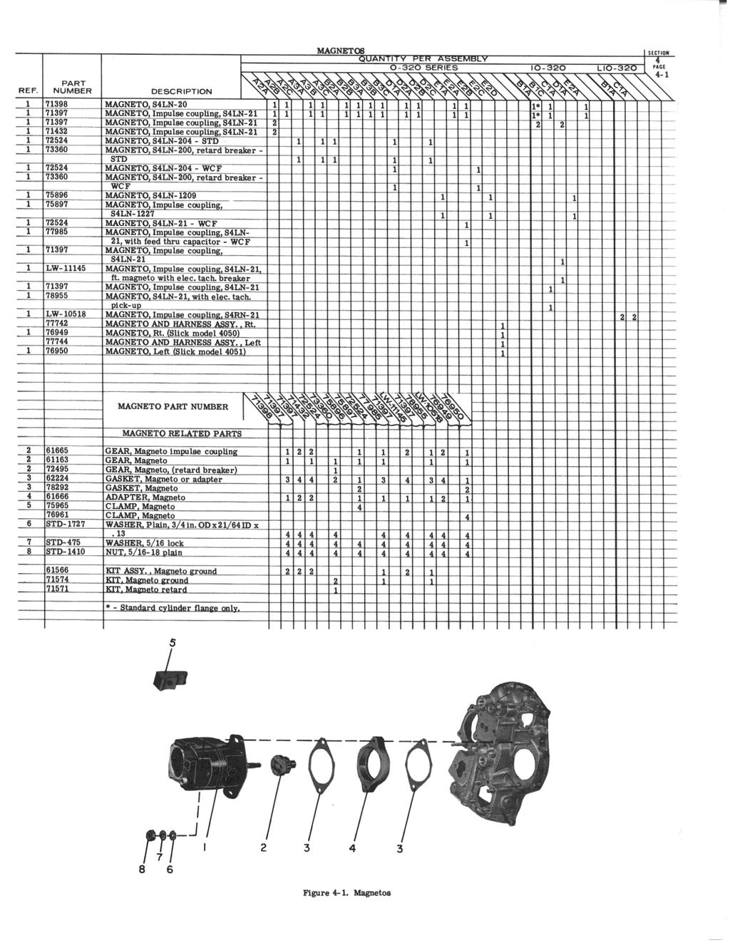
21 Page 3-3 Ref. No. Part No. Description Qty. Per Engine LW- 795 LW LW LW MS MS LW- 3 7 LW- 7 STD STD VALVE, Intake VALVE, Exhaust, rotator SPRING, Valve, inner SPRING, Valve, outer SEAT, Valve spring, lower, intake SEAT, Valve spring, lower, exhaust SEAT, Valve spring, upper, intake SEAT, Valve spring, upper, exhaust KEY, Valve, intake KEY, Valve, exhaust, rotator CAP, Valve stem, exhaust, rotator PLUNGER ASSY., Hydraulic tappet SOCKET, Push rod, hydraulic tappet TUBE, Push rod, shroud SPRING, Shroud tube LOCKPLATE, Shroud tube NUT, /-0 plain SEAL, Shroud tube SEAL, Shroud tube Page 3- Use column O-30-ED and NUT, /-0 plain SPACER, 33/6 ID x 7/ OD 3/ thick SECTION IGNITION SYSTEM Page - Ref. No. Part No. Description Qty. Per Engine MAGNETO AND HARNESS ASSY., Right MAGNETO, Right (Slick model 050) MAGNETO AND HARNESS ASSY., Left MAGNETO, Left (Slick model 05 - impulse coupling)
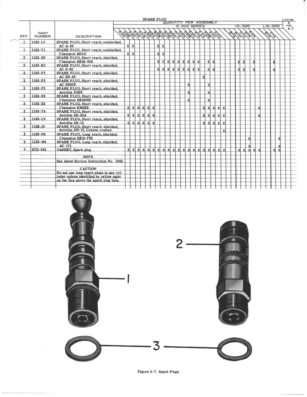
22 Ref. No. Part No STD LW- 706 LW STD STD- 75 STD Page - (Cont. ) Description GEAR, Magneto, impulse coupling COTTER PIN GEAR, Magneto GASKET, Magneto adapter and magneto ADAPTER, Magneto impulse coupling GASKET, Magneto CLAMP, Magneto WASHER, Plain, 3/ OD x /3 ID x / thick WASHER, 5/6 internal lock NUT, 5/6- plain ZIP STRAPS Page - Qty. Per Engine Not applicable. Page -3 Not applicable. Page - Not applicable. Page -5 Not applicable. Page -6 Use column ED. Page -7 - B6 SPARK PLUG, Champion EME 9
23 SECTION 5 ELECTRICAL SYSTEM Page 5- Not applicable. Page 5- Ref. No. Part No. Description Use column O-30-ED and the following on Beech applications only. Qty. Per Engine 3 STD- 5 BOLT, 5/6- x 9/3 long, hex. hd. dr. The following parts apply to Piper 0-30-E3D engines which were equipped with alternators, alternator brackets and attaching parts at Lycoming. LW STD STD- 35 STD- 7 STD STD- 7 STD- 33 AN6- STD-33 STD- 7 STD-73 AN STD- 33 STD- 7 STD- 73 BRACKET, Alternator LOCKPLATE, 5/6 bolt x. 00 spacing BOLT, 5/6- x 5/6 long, hex. hd. LINK, Alternator belt adjusting WASHER, 5/6 plain BOLT, 5/6- x 3/ long, hex. hd., dr. WASHER, Plain, 3/ OD x /3 ID x / thick STRUT, Alternator support BOLT, 5/6- x 3/ long, hex. hd., dr. WASHER, 3/ plain BOLT, 3/- x -37/6 long, hex. hd., dr. end WASHER, 3/ plain NUT, 3/-, slotted COTTER PIN BOLT, 3/- x -9/6 long, hex. hd., dr. end SHIM, -/ OD x 3/3 ID x. 005 thick WASHER, 3/ plain NUT, 3/- slotted COTTER PIN Page 5-3 Not applicable. 0 AR AR AR
24 Page 5- Ref. No. Part No. Description Qty. Per Engine * STD-35 3 STD-75 LW STD-56* 5 STD- 0 STARTER, volt, 0/ pitch STARTER, volt, / pitch WASHER, 5/6 plain WASHER, 5/6 internal lock BOLT, 5/6- x - 3/3 long, hex. hd. BOLT, 5/6- NUT, 5/6- plain * - Beech applications only. Page 5-5 Not applicable. SECTION 6 FUEL INDUCTION SYSTEM Page 6- Use references thru 5 only. Page 6- Ref. No. Part No. Description * 77 3 STD-35 STD- 0 5 STD- 763 GASKET, Carburetor CARBURETOR, ( ) CARBURETOR, (0-5009) WASHER, 5/6 plain NUT, 5/6- plain LOCKNUT, 5/6 palnut Qty. Per Engine * - Beech applications. Page 6-3 Not applicable.
25 Page 6- Not applicable. Page 6-5 Piper Applications Ref. No. Part No. Description Qty. Per Engine 0 PLUG, /-7 NPT, allen STD AN365-63C STD Beech Applications TUBE ASSY., Primer, 6-/6 long, cyls. and TUBE ASSY., Primer, -/6 long, cyls. 3 and TUBE ASSY., Primer, 0-5/6 long, intermediate CLIP, 3/6 ID for / dia. screw CLAMP, -3/ ID with / dia. offset SCREW, No. 6-3 x / long, rd. hd. NUT, No. 6-3, self lock TEE, Union, / tube NIPPLE ASSY., Primer SECTION 7 3 COOLING BAFFLES, EXHAUST, OIL GAGE AND PROPELLER GOVERNOR OIL LINE Page 7- Use column 0-30-ED. Page 7- Ref. No. Part No. Description Qty. Per Engine 653* ( GASKET, Exhaust flange 776** GASKET, Exhaust flange STD-35 WASHER, 5/6 plain 3 STD- 75 WASHER, 5/6 internal lock STD- 0 NUT, 5/6- plain * - Piper applications. ** Beech applications.
26 Ref. No. Part No STD LW LW- 79 STD Page 7-3 Piper Applications Description TUBE, Oil level gage, long GASKET, Oil level gage RING, Oil level gage GAGE ASSY., Oil level PLUG, Oil level gage PIN, /6 dia. x 7/6 long Beech Applications GASKET, Oil level gage TUBE ASSY., Oil level gage, -3/6 long TUBE, Oil level gage EXTENSION, Oil filler RING, Oil seal,. 00 ID x / section GAGE ASSY., Oil level DOWEL, 3/6 dia. x / long RING, Plug, oil level gage RING, Oil level gage bushing Page 7- Not applicable. Qty. Per Engine 3
27 SUPPLEMENTAL PARTS LIST SSP7 TO PROVIDE PARTS COVERAGE FOR LYCOMING MODEL 0-30-DF and 0-30-EF ENGINES This parts supplement is not arranged in the same format as PC-03, but it is based on the same page and reference numbers listed in PC-03. The departure appears when 0-30-DF or ElF engine parts are referred to under a particular column on the original catalog page. Parts listed under that column are the same on both DF and ElF engines unless otherwise specified. Example: Parts onpage -7 under column 0-30-EC are the same as onboth 0-30-DF and 0-30-ElF engines. Only those parts which are different, new, or require a different quantity than in PC-03 are listed. Pages in the original parts catalog which do not apply to 0-30-DF or 0-30-EIF engines are so designated. SSP7 PC- 03 February 973
28 O-30-DF, -ElF WIDE CYLINDER FLANGE AIRCRAFT ENGINES SECTION CRANKCASE, CRANKSHAFT AND CAMSHAFT Ref. No. Part Number Description Qty. Per Engine Model Usage LW-06 STD LW STD-5 STD D STD * Driven Height Driven Height Page - CRANKCASE ASSEMBLY DOWEL, Hollow, / in. dia. x 39/6 long STUD, /-0 x 0-/6 in. long STUD, /-0 x -7/ in. long STUD, 3/-6 x -5/ in. long 6 PLUG, Allen Hd., /-7 NPT RETAINER, Shroud Tube Seal STUD, 5/6- x 5/6 in. long STUD, 5/6- x -5/ in. long DOWEL, Crankshaft Bearing DOWEL, Crankshaft Bearing DOWEL, 5/6 in. dia. x / in. lg. INSERT, Heli-Coil, /-0 x 3/ in. long STUD, Drilled, 3/-6 x -/ in. long STUD, 5/6- x 5/6 in. long PLUG, Allen Hd., /6-7 NPT STUD, 5/6- x -/6 in. long STUD, 5/6- x. 00 in. long for P/N 636 is in. for P/N is.3 in. -DF, -ElF -DF, -ElF -DF, -ElF -DF, -ElF -DF, -ElF -DF, -ElF -DF, -ElF -DIF, -ElF -DF, -ElF -DF, -ElF -DF, -ElF -DF, -ElF -DF, -ElF -DF, -ElF -DF, -ElF -DF, -ElF -DF, -ElF -DF * 3 model -DF engines were manufactured with the in. long stud. Use only parts listed above for crankcase assembly. LW LW Page - BEARING, Crankshaft BEARING, Crankshaft, front SEAL, Crankshaft oil SEAL, Oil, in. section x 5/3 in. dia. SPRING, Oil pressure relief valve PLUG, Oil pressure relief valve -DF, -ElF -DF, -ElF -DF, -ElF -DF, -EF -DF, -ElF -DF, -ElF
29 0-30-DF, -ElF WIDE CYLINDER FLANGE AIRCRAFT ENGINES SECTION (CONT.) CRANKCASE, CRANKSHAFT AND CAMSHAFT Ref. No. Part Number Description Qty. Per Engine Model Usage Page - (cont. ) For other parts applicable to 0-30-DF, - EF model engines use figure reference numbers Page -3 For all parts on page -3 applicable to 0-30-DF, -EF model engines use column under 0-30-DA (WCF) listings. Use illustration Ref. -B for prop. flange bushing locations. LW Page - NUT, Connecting Rod CAMSHAFT -DF, -ElF -DF, -EF For other parts applicable to 0-30-DF, -ElF model engines use column under 0-30-DA. STD-33 AN960-66L AN6-3A Page -5 WASHER, Plain, 3/ in. 5 WASHER, Plain (Thick) 3/ in. AR BOLT, Hex. Hd., 3/- x 3-37/6 long STUD, /-0 x 0-5/6 in. long -DF,-EF -DF, -EF -DF, -EF -DF, -EF For other parts applicable to 0-30-DF, -EF model engines use column under 0-30-DA (WCF) Page -6 GEAR, Starter Ring, / Pitch -DF, -EF For other parts applicable to 0-30-DF,-ElF model engines use column under 0-30-DA except for those figure references marked "c" and Page -7 For all parts on this page applicable to 0-30-DF, engines use column under 0-30-DA. 3 -EF model
30 0-30-DF, -EF WIDE CYLINDER FLANGE AIRCRAFT ENGINES SECTION ACCESSORY HOUSING AND DRIVES Ref. No. Part Number Description Qty. Per Engine Model Usage Page - Page - does not apply to 0-30-DF, -EF model engines. Page - For accessory housing P/N applicable to 0-30-DF, -EF model engines, use column under 0-30-DA. For remaining parts use column under STD LW STD-35 STD STD- 0 STD-0 STD-60 STD- STD- 973 Page -3 BODY ASSY., Oil pump PLUG, /6-7 NPT allen hd. SHAFT, Oil pump drive IMPELLER, Oil pump driving IMPELLER ASSY., Oil pump driven WASHER, 5/6 plain NUT, 5/6- slotted SEAL, tachometer drive, oil WASHER, / plain BOLT, /-0 x 5/6 long, hex. hd. WASHER, / internal lock BOLT, /-0 x -/ long, hex. hd. KEY, / x 3/ dia. Woodruff 3 0 -DF, -ElF -DF, -ElF -DF, -ElF -DF, -EF -DF, -ElF -DF, -ElF -DF, -ElF -DF, -EF -DF, -ElF -DF, -ElF -DF, -ElF -DF, -ElF -DF, -ElF Page - STD-7 PLUG, 3/ pipe, Allen For other parts use O-30-ED. Refs., 3,, 5, 6, 7,,7, Do not use Refs. 9 thru DF engines were built with P/N 73 (Ref. 3) -DF, -ElF and 3. Page -5 Use column under 0-30-DA and: STD GEAR, Propeller governor, driven SHAFT, Prop. gov. idler gear GEAR ASSY., Prop gov. idler DOWEL,.0907 dia. x. long BUSHING -DF, -ElF -DF, -ElF -DF, -ElF -DF, -ElF -DF, -ElF
31 O-30-DF, -ElF WIDE CYLINDER FLANGE AIRCRAFT ENGINES SECTION (CONT.) ACCESSORY HOUSING AND DRIVES Ref. No. Part Number Description Qty. Per Engine Model Usage STD MS DOWEL,.09 dia. x. long WASHER, Thrust WASHER, Thrust WASHER, Thrust WASHER, Thrust PIN, Spring, / dia. x -3/ long GASKET,.7 ID x -/ OD x.06 thick PLUG, 3/-6 hex hd. AR AR AR AR DF, -ElF DF, -ElF DF, -ElF DF, -ElF DF, -ElF DF, -ElF DF, -ElF DF, -ElF Page -6 Use column under O-30-DA, References thru 5 only. Page -7 Use column under O-30-DA use P/N STD-73. (WCF) References 9 thru only. Do not Page - Page - does not apply to model O-30-DF or O-30-EF engines. LW-0 79 STD- 0 3 STD- STD-60 5 STD- STD-9 LW-55 Page -9 SUMP ASSY., Oil CONNECTION, Intake Pipe BOLT, Hex. hd. /-0 x 5/6 lg. WASHER, / plain WASHER, / internal lock NUT, /-0 plain BOLT, /-0 x -/ long, hex hd. PLUG, 5/ x thd., hex hd. 0 DF, DF, DF, DF, D F, DF, DF, DF, -ElF -ElF -ElF -ElF -ElF -ElF -ElF -ElF For other parts use column under O-30-DA. SECTION 3 CYLINDER, PISTON, AND VALVE TRAIN 7509 Page 3- PISTON,.50: -DF 5
32 0-30-DF, -EF WIDE CYLINDER FLANGE AIRCRAFT ENGINES SECTION 3 (CONT.) CYLINDER, PISTON, AND VALVE TRAIN Ref. No. Part Number Description Qty. Per Engine Model Usage Page 3- (Cont.) PISTON, 7.00: RING, Piston, Compressior RING, Piston, Compressior RING, Piston, Compressior RING, Piston, Compressior RING, Piston, Oil Regulatir Expander PIN, Piston PIN, Piston PLUG, Piston pin Use above parts only. LW-6 LW STD-7 0 Page 3- CYLINDER & HEAD ASSY., Nitrided CYLINDER & HEAD ASSY., Nitrided GUIDE, Valve, Intake GUIDE, Valve, Exhaust INSERT, /-7 helicoil taper pipe thd. PLUG, /-7 NPT, Allen -DF -ElF -DF, -ElF -DF, -ElF -DF -DF, -EF For other parts use column under 0-30-DA. 3 LW-795 LW LW-73 7 LW Page 3-3 SPRING, Valve, Inner SPRING, Valve, Outer SOCKET, Push Rod, hydraulic tappet SOCKET, Push Rod, hydraulic tappet TUBE, Push Rod, Shroud SPRING, Shroud tube LOCKPLATE SEAL, Shroud tube -DF, -EF -DF, -ElF -DF, -EF -DF, -EF -DF, -EF -DF, -EF -DF, -ElF -DF, -E F For other parts on model 0-30-DF use 0-30-DA. For other parts on model 0-30-EF use 0-30-EA but do not use Ref. 5. 6
33 O-30-DF, -EF WIDE CYLINDER FLANGE AIRCRAFT ENGINES SECTION 3 (CONT.) CYLINDER, PISTON, AND VALVE TRAIN Ref. No. Part Number Description Qty. Per Engine Model Usage 5 STD Page 3- NUT, /-0 plain SPACER, 33/6 ID x 7/ OD x 7/ thick -DF, -EF -DF, -EF For other parts use O-30-DA (WCF) only. SECTION IGNITION SYSTEM LW LW LW- 6 Page - MAGNETO, SLN-09 MAGNETO, Impulse coupling (SLN-7) GASKET, Magneto -DF, -DF, -EF -EF -DF,-EF For other parts use magneto P/N Do not use Reference 3. Page - Does not apply. LW-0 LW- 0 LW-0 STD- STD-60 AN STD-696 Page -3 TERMINALS, Spark Plug Wire SPRING, Spark Plug Terminal COLLAR (Silicone) Spark Plug Terminal WASHER, Plain, / in. WASHER, Internal Lock, / in. SCREW, /-0 x 3/ in. long WASHER, Plain, Thin AR -DF, -EF -DF, -EF -DF,-EF -DF, -EF -DF, -EF -DF, -EF -DF, -EF For all other parts except those listed above, use column under O-30-DC. Do not use P/N Pages -, -5, -6 Do not apply 7
34 O-30-DF, -ElF WIDE CYLINDER FLANGE AIRCRAFT ENGINES SECTION (CONT.) IGNITION SYSTEM Ref. No. Part Number Description Qty. Per Engine Model Usage -B3 -B6 Page -7 SPARK PLUG SPARK PLUG -DF -ElF Use above parts only. SECTION 5 ELECTRICAL SYSTEM Page 5- Does not apply. Page 5- Use column O-30-DA References 6 thru 5 only * Page 5-3 ALTERNATOR, volt-0 amp ALTERNATOR, volt-0 amp -DF, -ElF -DF * 5 O-30-DF engines were built equipped with this alternator. Use the above parts only. STD-56 LW-03 Page 5- BOLT, 5/6- x -5/3 long, hex hd. SWITCH, Magnetic, volt -DF, -ElF -DF, -ElF For all other parts use column O-30-EB. LW Page 5-5 REGULATOR, volt OVERVOLTAGE RELAY, volt I -DF, -ElF -DF, -ElF SECTION 6 FUEL INDUCTION SYSTEM Page 6- Use O-30-AA Refs. thru only.
35 O-30-DF, -ElF WIDE CYLINDER FLANGE AIRCRAFT ENGINES SECTION 6 FUEL INDUCTION SYSTEM Ref. No. Part Number Description Qty. Per Engine Model Usage Page 6- Use O-30-AA Refs. thru only. Page 6-77 CARBURETOR, Model MA-SPA Marvel-Schebler WCF For other parts use O-30-AA -DF, -EF Pages 6-3, 6-, Do not apply SECTION 7 COOLING BAFFLES, EXHAUST, AND OIL GAGE Page 7- Use 0-30-ED Page 7- Use O-30-DC Page 7-3 TUBE, Oil level gage, intermediate TUBE, Oil level gage, long GASKET, Oil level gage RING, Oil level gage seal RING, Oil level gage seal GAGE ASSY., Oil level GAGE ASSY., Oil level -DF -ElF -DF, -EF -DF -ElF -DF -ElF Use above parts only. Page 7- Does not apply. 9
36 SERVICE REPLACEMENT SETS MODEL 0-30-DF AND 0-30-EF ENGINES SEAL AND GASKET SET PART NO. DESCRIPTION QTY. PER ENGINE LW STD-0 STD STD STD LW GASKET, Governor drive GASKET, Vacuum pump SEAL, Shroud tube GASKET, Fuel pump GASKET, Intake flange GASKET, Carburetor SEAL, Crankshaft oil GASKET, Oil suction tube flange RING, Oil level gage seal SEAL, Tachometer shaft GASKET, Oil pressure housing GASKET, Accessory adapter GASKET, Rocker box cover GASKET, Accessory housing GASKET, Oil sump GASKET, Hydraulic valve GASKET, Magneto adapter GASKET, Exhaust flange GASKET, Carburetor SEAL, Oil GASKET, Accessory drive adapter SEAL, Shroud tube SEAL, Oil GASKET, Annular SEAL, Oil RING, Oil seal GASKET, Annular CONTAINER GASKET, Accessory pad cover GASKET, Dual Accessory drive cover GASKET, Governor spacer SEAL, Oil GASKET, Carburetor RING, Oil level gage seal LOCKPLATE, Crankshaft gear GASKET GASKET SPACER SPRING LOCKPLATE, Camshaft gear 0 6
37 SEAL AND GASKET SET (CONT.) PART NO. DESCRIPT ION QTY. PER ENGINE 737 LW-7 LW-795 STD- STD-3 69-C LW-6 LOCKPLATE, Crankshaft idler gear shaft LOCKPLATE, Shroud tube GASKET GASKET SEAL GASKET GASKET LOCKPLATE RING, Oil seal LOCKPLATE RING, Oil seal MAGNETO GASKET CYLINDER, PISTON, AND RING ASSEMBLY KIT 0-30-DF ENGINES HIGH COMPRESSION CHROME CYLINDER SET MS MS STD- STD LW LW-795 LW LW-73 LW LW SET #7639 KEY, Valve, exhaust CAP, Valve stem NUT, /-0 plain SCREW, /-0 x 5/ long, Fill hd., self lock KEY, Valve SEAL, Shroud tube SHAFT, Valve rocker COVER, Rocker box SPRING, Valve Outer SEAT, Valve spring, lower SPRING, Valve, Auxiliary SEAT, Valve spring SPRING, Shroud tube LOCKPLATE, Shroud tube SPACER, Shroud tube spring ROCKER ASSY., Valve, intake PIN, Piston SEAL, Shroud tube BOX, Set up RING, Oil seal,. 09 dia. sect. x. ID PLUG, Piston pin (Alum. bronze) SEAT, Valve spring 6
38 SET #7639 (CONT.) PART NO. DESCRIPTION QTY. PER ENGINE 7393 VALVE, Intake 7399* RING, Piston, Oil regulating 75 VALVE, Exhaust (rotator type) 755 SEAT, Valve spring, lower, exhaust 7636 ROCKER ASSY., Valve, exhaust 7673* RING, Piston, compression 7509 PISTON GASKET, Rocker box cover LW-9 CYLINDER AND HEAD ASSY. STD-5 BOLT 60 PLUG, Piston pin (Alum.) SSP-7 TAG * - Half Wedge Rings 0-30-DF High Compression Nitrided Cylinder Set SET # * RING, Oil regulating, expander type 7* RING, Piston, compression LW-6 CYLINDER AND HEAD ASSY. All other parts are the same as in set #7639, but donot use P/N 79-Piston Pin Plug. * - Half Wedge Rings O-30-EF Low Compression Steel Cylinder Sets SET # PIN Piston 7357* RING, Oil regulating 7506 VALVE, Exhaust (Rotator type) 799* RING Piston, compression 753 PISTON LW-7 CYLINDER AND HEAD ASSY. Allotherparts arethe sameas in set#7639, but donot usep/n 79-PistonPin Plug. * - Half Wedge Rings SET # A * * 753 PIN, Piston (Heavy) RING, Oil Regulating VALVE, Exhaust (Rotator type) RING, Piston, Compression PISTON
39 SET # A (CONT.) QTY. PER PART NO. DESCRIPTION ENGINE LW-7 CYLINDER AND HEAD ASSY. All other parts are the same as in set #7639, but do not use P/N 79-Piston Pin Plug. * - Half Wedge Rings O-30-EF Low Compression Chrome Cylinder Sets SET # PIN, Piston 7506 VALVE, Exhaust (rotator type) 753 PISTON SET #753-A 7757 PIN, Piston (heavy) 7506 VALVE, Exhaust (rotator type) 753 PISTON All other parts are the same as in set #7639, but do not use P/N 79-Piston Pin Plug. 3
40 SUPPLEMENTAL PARTS LIST NO. SSP77 To provide parts coverage for Lycoming IO-30- DB MODEL ENGINES. This parts supplement is not necessarily arranged in the same basic format as the original publication PC-03. However, it is arranged to provide parts coverage by using the same page as listed in the basic catalog. The departure, therefore, appears when IO-30-DB engine parts are referred to a particular column on the basic catalog page. For example: The piston assembly for IO-30- DB model engines may be referred to as under column headed by IO-30-DIA. This means that allparts listedunder this heading also apply toio-30-db model engines and the only listings present in the supplement will be those parts that are different, new or parts that require a different quantity per engine assembly. Any pages listed in the basic catalog, PC-03, not applicable to the IO-30-DB model engine, will be so designated in this supplement. SSP 77 PC-03 November, 97
41 LYCOMING AIRCRAFT ENGINE GROUP ASSEMBLY PARTS LIST IO-30-DB MODEL ENGINES SECTION CRANKCASE, CRANKSHAFT AND CAMSHAFT REF. PART DESCRIPTION QTY. MODEL NO. NUMBER 3 5 ENG. USAGE Page - LW-06 CRANKCASE ASSEMBLY 50-5 STUD,./-0 x -7/ in. long STUD, 3/-6 x -5/ in. long 6 3- STUD, 3/-6 x -3/ in. long 75 BUSHING, Gov. drive idler shaft 0 PLUG, Allen, /-7 NPT 5 STD- 339 PLUG, Allen, /6-7 NPT 636 STUD, 5/6- x -/6 in. long (Driven height of studs in. for crankcase service assembly) For all other parts applicable to IO-30-DB use column under IO-30-CA except figure reference numbers 6, 7, 7 and. Page BEARING, Crankshaft front SEAL, Oil, in. section x 0. 7 in. ID For all other parts applicable to IO-30-DB use column under IO-30-CA except figure reference numbers 3**, **, 5** and 6**, and 6 do not apply. Page -3 Use column under model engines. IO-30-DA for IO-30-DlB Page - Figure references No., P/N 676-S and No. 3, P/N 7667 do not apply to IO-30-DIB model engines CAMSHAFT ASSEMBLY NOTE Figure reference numbers 7 thru do not apply to IO-30-DB model engines. Page -5 AN6-3A BOLT, Hex. hd., 3/- x 3-37/6 in. long STD-33 WASHER, Plain, 3/ in. STD- WASHER, Plain, / in. 9 STD-60 WASHER, Internal lock, / in. STD- NUT, Plain, / AN960-66L WASHER, Plain, 3/ in. (thick). Max. 3 pcs. AR STUD, /-0 x 0-5/6 in. long For other crankcase attaching parts except those listed above, use column headed IO-30-DA. Item 0 does not apply to IO-30-DB model engines.
42 LYCOMING AIRCRAFT ENGINE GROUP ASSEMBLY PARTS LIST IO- 30-DB MODEL ENGINES SECTION I (CONT.) CRANKCASE, CRANKSHAFT AND CAMSHAFT REF. PART DESCRIPTION QTY MODEL PER NO. NUMBER 3 5 ENG.USAGE Page -6 NOTE Figure reference numbers 3 thru 3 do not apply to IO-30-DB model engines. Use column headed IO-30-DA listed on Page -6. for all other parts Page -7 Figure reference numbers 6 thru 9 and listed in column headed IO-30-DA are the only parts listed on Page -7 applicable to IO-30-DB model engines. SECTION ACCESSORY HOUSING AND DRIVES Page - Use column headed IO-30-DA for IO-30-DB model engines. Page BODY ASSEMBLY, Oil pump 3 STD- 339 PLUG, Allen hd., /6-7 NPT 753 IMPELLER ASSEMBLY, Oil pump driven 7530 SHAFT, Oil pump idler IMPELLER, Oil pump driven 75 SHAFT, Oil pump drive IMPELLER, Oil pump driving STD- 973 KEY, Woodruff, / x 3/ dia. STD-35 WASHER, Plain, 5/6 in. 3 STD- 0 NUT, Slotted, 5/ SEAL, Tachometer drive, oil 0 STD- WASHER, Plain, / in. 0 STD-60 WASHER, Internal lock, / in. 0 STD-0 BOLT, Hex. hd., /-0 x 5/6 in. long 0 STD- BOLT, Hex. hd., /-0 x -/ in. long Page - LW-069 VALVE ASSEMBLY, Temp. control oil cooler. by-pass NOTE Figure reference numbers 0 thru do not apply to IO-30-DB model engines as shipped from the factory. For all other parts applicable to IO-30-DB model engines listed on Page - use column headed IO-30-DA. Page -5 Use column headed IO-30-DA for IO-30-DB model engines. 3
43 FORM 633 LYCOMING AIRCRAFT ENGINE GROUP ASSEMBLY PARTS LIST IO-30-DB MODEL ENGINES SECTION (CONT.) ACCESSORY HOUSING AND DRIVES REF. NO. PART NUMBER 3 5 DESCRIPTION QTY. PER ENG. MODEL USAGE Page STD-9 STD MS Use column headed IO-30-DA for IO-30-BB model engines. NOTE Figure reference numbers 6 thru 7 on Page -6 do not apply to IO-30-DB model engines as shipped from the factory. GEAR, Propeller governor driven SHAFT, Propeller gov. idler gear GEAR ASSEMBLY, Prop. gov. idler BUSHING, Prop. gov. idler gear DOWEL, dia. x 7/3 in. long DOWEL, dia. x 9/3 in. long WASHER, Thrust WASHER, Thrust WASHER, Thrust WASHER, Thrust PIN, Spring, / in. dia. x -3/ in. long GASKET, 7/ in. ID x -/ OD x /6 in. thick PLUG, 3/ in. hex. hd., -6 thread Page -7 Figure reference numbers thru are not applicable to IO-30-DB model engines. Use all figure reference numbers 9 thru on IO-30-DB model engines, if required. Page - AR AR AR AR This page does not apply to IO-30-DB model engines. Page -9 LW STD- 0 STD-9 SUMP ASSEMBLY, Oil CONNECTION, Intake pipe BOLT, Hex. hd., /-0 x 5/6 in. long BOLT, Hex. hd., /-0 x -/ in. long For all other parts listed on Page -9, which are applicable to IO-30-DB model engines, use column headed IO-30-DA. SECTION 3 CYLINDER, PISTON AND VALVE TRAIN Page 3- Use all columns opposite first listing of cylinder assembly, P/N 750-N for IO-30-DB model engines. On illustration page use light piston pin, P/N and P/N 60 piston pin plug for IO-30-DB model engines.
44 FOR 633 LYCOMING AIRCRAFT ENGINE GROUP ASSEMBLY PARTS LIST IO-30-DlB MODEL ENGINES SECTION 3 (CONT.) CYLINDER, PISTON AND VALVE TRAIN REF. NO. PART NUMBER 3 5 DESCRIPTION QTY. PER ENG. MODEL USAGE Page STUD, /-0 x -/6 in. long For all other cylinder assembly parts, except that listed above, use column headed by IO-30-DIA for IO-30-DB model engines. Page LW-795 LW SPRING, Valve, inner SPRING, Valve, outer SOCKET, Push rod, hydraulic tappet TUBE, Push rod shroud SEAL, Shroud tube For all other related valve parts use column headed IO-30-DA for IO-30-DB model engines. Page SPACER, 33/6 ID x 7/ OD x 3/ in. thick STD-090 NUT, Plain, /-0 For all other related push rod and intake pipe parts use column headed IO-30-DA for IO-30-DB model engines. SECTION IGNITION SYSTEM Page MAGNETO, SLN- 09 MAGNETO, SLN-7, Impulse coupling For all magneto related parts use column headed P/N 7597 for IO-30-DB model engines. Page - This page does not apply to IO-30-DB model engines. Page IGNITION HARNESS, 00 series mags., straight valve head For related ignition harness parts use column headed IO-30-DA for IO-30-DB model engines. NOTE Following is a complete listing of harness attaching parts, which differs somewhat from basic catalog. 5
45 LYCOMING AIRCRAFT ENGINE GROUP ASSEMBLY PARTS LIST IO-30-DB MODEL ENGINES SECTION (CONT.) IGNITION SYSTEM REF. NO. PART NUMBER 3 5 DESCRIPTION QTY. PER ENG. MODEL USAGE Page -3 (cont. ) STD- 039 STD- 60 AN STD-696 ZIP STRAPS CLAMP, Rubber dip, -wire CLAMP, Rubber dip, -wire CLAMP, Rubber dip, -wire WASHER, Plain, / in. PROTECTOR, Ignition cable (top leads) WASHER, Internal lock, / in. SCREW, /-0 x 3/ in. long WASHER, Plain, / in., thin Page - thru -6 6 AR These pages do not apply to IO-30-DB model engines. Page -7 Use column headed IO-30-DA for IO-30-DB model engines. SECTION 5 ELECTRICAL SYSTEM Page 5- This page does not apply to IO-30-DB model engines. Page 5- NOTE Figure reference numbers thru 5 do not apply to IO-30-DB model engines. For figure reference numbers 6 thru 5 use column headed IO-30-DA for IO-30-DIB model engines. Page ALTERNATOR ASSEMBLY, v-50 amp., 3.5:ratio Page BELT, Alternator drive, 3/ in. 76 STARTER, volt, / pitch, 3. 3:, internal reduction LW- 03 SWITCH, Magnetic For all other parts except those listed above, use column headed IO-30-DA for IO-30-DB model engines. Page 5-5 LW-05 REGULATOR, volt, full transistor 7059 RELAY, Overvoltage, volt 6
46 LYCOMING AIRCRAFT ENGINE GROUP ASSEMBLY PARTS LIST IO-30-DB MODEL ENGINES SECTION 6 FUEL INDUCTION SYSTEM REF. NO. PART NUMBER 3 5 DESCRIPTION QTY. PER ENG. MODEL USAGE Page STD-33 STD GASKET, Fuel pump FUEL PUMP, Dual diaphragm WASHER, Plain, 3/ in. SCREW, Socket hd., drilled hd., 3/-6 x -9/3 long ELBOW, 5/6 in. tubing, 9/6- adjustable 90 (Assemble aftapprox. 5 above centerline of fuel pump inlet) NOTE Parts listed above on Page 6- are only parts applicable to IO-30-DB model engines. Page 6- This page does not apply to IO-30-DB model engines. LW LW STD-60 STD-670 LW Page 6-3 Use column under IO-30-DA for IO-30-DB model engines. Page 6- TUBE ASSEMBLY, Fuel manifold to nozzle, Cyl. No. and 3 (0 in. long) TUBE ASSEMBLY, Fuel manifold to nozzle, Cyl. No. and CLIP, 3/ in. ID for 3/6 in. screw SCREW, Fill. hd., #0-3 x 5/ in. long NUT, Self-locking, #0-3 CLIP, / in. ID for #0 screw BRACKET, 90 For all other fuel injector plumbing, except those parts listed above, use column listed under IO-30-DA for IO-30-DB model engines. Page PLUG, Allen head, /-7 NPT SECTION 7 COOLING BAFFLES, EXHAUST, OIL GAGE AND PROP. GOVERNOR OIL LINE Page 7- Use column under IO-30-DA for IO-30-DB model engines. Page 7- Use column under IO-30-DA DB model engines. model engines for IO-30-7
47 FOr 633 LYCOMING AIRCRAFT ENGINE GROUP ASSEMBLY PARTS LIST IO-30-DB MODEL ENGINES SECTION 7 (CONT.) COOLING BAFFLES, EXHAUST, OIL GAGE AND PROP. GOVERNOR OIL LINE REF. NO. PART NUMBER 3 5 DESCRIPTION QTY. PER ENG. MODEL USAGE Page 7-3 Use column under IO-30-DA IO-30-DB model engines. model engines for Page 7- Page 7- is not applicable to IO-30-DB model engines.
48 Lycoming Textron Lycoming/Subsidiary of Textron Inc SUPPLEMENT No. SSP- 65 Oliver Street Williamsport, PA 770 U.S.A. 77/33-6 TECHNICAL PUBLICATION SUPPLEMENT ENGINE MODEL 0-30, 0-30 and LIO-30 Series PUBLICATIO No. PC-03 PUBLICATION DATE April, 970 This supplement is arranged in the same basic format as the original parts catalog Insert in front of catalog for useage of subject matter. August, 9 Page of Figure -3, Crankshaft Assembly Superseded Engine Model No 0-30* Letter Designation Propeller Bushings 3/ inch Superseded By Engine Model 0-30-A3A** Propeller Bushings 7/6 inch 0-30-AA 3/ inch 0-30-A3A** 7/6 inch 0-30-A B 0-30-BA 0-30-BB 3/ inch 0-30-A3B** 3/ inch 0-30-B3A** 3/ inch 0-30-B3B** 7/6 inch 7/6 inch 7/6 inch * Same as 0-30-AA. ** Parts for this engine are currently listed in PC-03 Parts Catalog dated April, 970. NOTE This supplemental parts list and illustration provides an engine parts comparison between current and superseded engine models. All parts for engine models in the above chart marked with an asterisk (*) are the same as parts for the superseded engine models with the exception of the Crankshaft Assy. and propeller mounting bushings and'locations.
49 l Lycoming 0-30, CRANKCASE, CRANKSHAFT AND CAMSHAFT GROUP CRANKSHAFT AND RELATED PARTS 0-30, LIO-30 SERIES PARTS CATALOG STANDARD CYLINDER FLANGE CRANKCASE MODEL ENGINES FIG. REF. -3 QUANTITY PER ASSEMBLY PART NUMBER DESCRIPTION 0-30, 0-30-AA, AB, BA and BB 66* STD S 7067-S S CRANKSHAFT ASSEMBLY PLUG,.00 dia. expansion BUSHING, Propeller flange, index BUSHING, Propeller flange BUSHING, Propeller flange, short PLUG, -3/ O.D. 3 * No longer available. Order Crankshaft Assembly Part No. 750 as a replacement. Refer to latest edition of Service Instruction No. 09 for bushing application. NO. 3 CRANKPIN 5 5 SSP- Page of
50 LYCOMING AIRCRAFT ENGINE GROUP ASSEMBLY PARTS LIST 0-30, IO-30, LIO-30 SERIES INTRODUCTION. GENERAL. This illustrated parts catalog lists herein. and describes all procurable parts for the Lycoming engines listed. SUPERSEDURE SECTION. This section lists part numbers in numerical sequence, first by superseded number to the new, or superseding part number. The second portion of this section lists the superseding, or new part number to the old or superseded number. 3. GROUP ASSEMBLY PARTS LISTS. This catalog is laid out in graph format indicating engine model number on each text page. The sections of this catalog divide the engine into various assemblies and related parts. These parts are listed in the order of engine assembly at the factory. Illustrations are on the page directly opposite or beneath the part description. The "Figure Reference Number" column (with heading "REF") provides cross reference to the part illustration. Those parts not numbered in this column are not illustrated. The "Part Number" column contains the Lycoming, AN, MS, or vendor part number. The "Description" column provides description or dimensional information required to describe the part. Subcolumns are employed here to differentiate parts of assemblies or sub-assemblies. Notes appearing in the text should be checked prior to ordering parts. All references to Lycoming Service Bulletins, Instructions and Letters should be fully observed. The letters (STD) appearing beside the part description means this part fits an engine manufactured with the Standard cylinder base flange. The letters (WCF) means this part fits an engine manufactured with the wide cylinder base flange. When neither appears in the description column, the part is applicable to either configuration. The "Quantity Per Assembly" portion of the text page indicates by model number the quantity required to complete the assembly on that page.. SERVICE REPLACEMENT SET SECTION. This section consists of the seal and gasket set applicable to the 0-30 series engine. Individual tained in kits are also listed in the group assembly parts list and may be procured separately. parts con- 5. VENDOR ITEMS SECTION. This section consists of assemblies produced by manufacturers other than Lycoming, for use on Lycoming engines. Numbers in "Part Number" column are those of the particular vendor. Parts for these assemblies can be obtained by ordering from Lycoming, Williamsport, Pa. 6. NUMERICAL INDEX. This section lists all part numbers contained in the group assembly numerical sequence. Column headings are self-explanatory. parts list (Sections thru 7), in alpha- 7. INSTRUCTIONS FOR ORDERING PARTS. Use of this catalog is keyed to engine model number. The model number can best be determined by visual inspection of the name plate located on the oil sump. Series of engines identified by the letter "A" following the serial number suffix are manufactured with the wide cylinder base flange. Example: 0-30-A, Serial Number L A. After engine model number and type cylinder flange is determined, look in the Table of Contents for the part, or for the assembly on which it would normally be found. If the part number is known, look in the numerical index (Section 0) in the back of the catalog. The illustrations can also be used to aid in finding the part.. OPTIONAL ITEMS. Those optional items, such as electrical system components, vacuum and hydraulic dual drives etc., are catalogued by engine model number as the engine was assembled at the factory. See appropriate Service Instructions for further information. Use the illustrations to aid in determining the option you desire. i
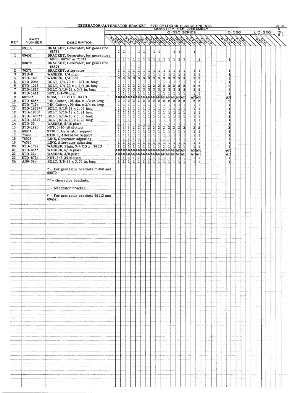
51 LYCOMING AIRCRAFT ENGINE GROUP ASSEMBLY PARTS LIST 0-30, IO-30, LIO- 30 SERIES TABLE OF CONTENTS SECTION INTRODUCTION TABLE OF CONTENTS... SUPERSEDURE SECTION... PAGE i... ii ii...iv iv Crankcase, Crankshaft and Camshaft Crankcase Assembly... Crankcase Related Parts.. Crankshaft Assembly.. Connecting Rod... Camshaft... Crankcase Attaching Parts... Support Assembly, Starter Ring Gear Accessory Idler Shafts... Propeller Flange and Spacer... Fuel Pump Drive and Idler Gears Accessory Housings and Drives Accessory Housing - Separate Cam Gear... Accessory Housing - Integral Cam Gear... Oil Pump... Accessory Housing Attaching Parts... Oil Cooler and Oil Filter... Vacuum Pump Drive.... Dual Drive, Vacuum Pump and Hydraulic Pump. Dual Drive, Vacuum Pump and Propeller Governor. Propeller Governor Drive Shaftgear.. Cover, Vacuum Pump... Cover, Vacuum and Hydraulic Pump.. Cover, Fuel Pump... Propeller Governor Drive Adapter... Cover, Governor Drive.... Cover, Governor Drive Adapter... Sump Assembly... Sump Assembly Cylinder, Piston and Valve Train Cylinder, Piston, Ring and Valve Application. Cylinder Assembly... Valve Seats and Guides... Spark Plug Inserts... Valves, Springs and Plungers... Shroud Tubes... Valve Rocker Assemblies... Valve Push Rods... Valve Rocker Drain Tubes... Intake Pipes Ignition System Magnetos... Unshielded Harness... Harness Assy., 5MM, Avco Lycoming... Harness Assy., Scintilla, -00 Series Magnetos Harness Assy., Scintilla, -00 Series Magnetos. Harness Assy., Slick... Spark Plug Electrical System Generator/Alternator Brackets, Standard Cylinder Flange Engines Generator/Alternator Brackets, Wide Cylinder Flange Engines ii
52 LYCOMING AIRCRAFT ENGINE GROUP ASSEMBLY PARTS LIST 0-30, IO-30, LIO-30 SERIES TABLE OF CONTENTS (CONT. ) SECTION Electrical System (Cont. ) Generator/Alternator.. Generator/Alternator Drive Belt. Starter... Magnetic Switch... Voltage Regulator and Relay. 6. Fuel Induction System Fuel Pump... Carburetor... Fuel Injector... Fuel Injection Tubes.. Priming System... PAGE Cooling Baffles, Exhaust, Oil Gage and Propeller Governor Oil Line Intercylinder Cooling Baffles... Exhaust Flanges and Gaskets... Oil Level Gages... Propeller Governor Oil Line Service Replacement Set Section Vendor Accessories Delco-Remy Generator. Delco-Remy Alternator... Prestolite Alternator... Prestolite Starter.. Bendix Scintilla Magnetos: -0 Series Series Series.. Lear-Siegler Fuel Pump.. Marvel-Schebler Carburetor. Bendix Fuel Injector Numerical Index iii
53 LYCOMING AIRCRAFT ENGINE GROUP ASSEMBLY PARTS LIST LYCOMING PARTS CATALOG 0-30, IO-30 AND LIO-30 SERIES SUPERSEDURE SECTION
54 LYCOMING AIRCRAFT ENGINE GROUP ASSEMBLY PARTS LIST SUPERSEDED PARTS SUPERSEDED P/N 0G 79B STD- 9 STD-336 STD S SUPERSEDING P/N S LW SUPERSEDED P/N SUPERSEDING P/N LW- 0 LW LW LW LW iv
55 LYCOMING AIRCRAFT ENGINE GROUP ASSEMBLY PARTS LIST SUPERSEDED PARTS SUPERSEDED P/N SUPERSEDING P/N SUPERSEDED P/N SUPERSEDING P/N LW- 039 LW- 03 LW- 000 LW LW LW LW LW v
56 LYCOMING AIRCRAFT ENGINE GROUP ASSEMBLY PARTS LIST SUPERSEDED PARTS SUPERSEDING P/N SUPERSEDED P/N B STD STD G STD SUPERSEDING P/N S SUPERSEDED P/N S vi
57 LYCOMING AIRCRAFT ENGINE GROUP ASSEMBLY PARTS LIST SUPERSEDED PARTS SUPERSEDING P/N SUPERSEDED P/N SUPERSEDING P/N SUPERSEDED P/N LW LW LW-0 LW- 079 LW- 05 LW- 03 LW- 039 LW LW- 000 LW- 075 LW- 079 LW LW- 0 LW vii
58 LYCOMING AIRCRAFT ENGINE GROUP ASSEMBLY PARTS LIST LYCOMING PARTS CATALOG 0-30, IO-30 AND LIO-30 SERIES SECTION CRANKCASE, CRANKSHAFT AND CAMSHAFT

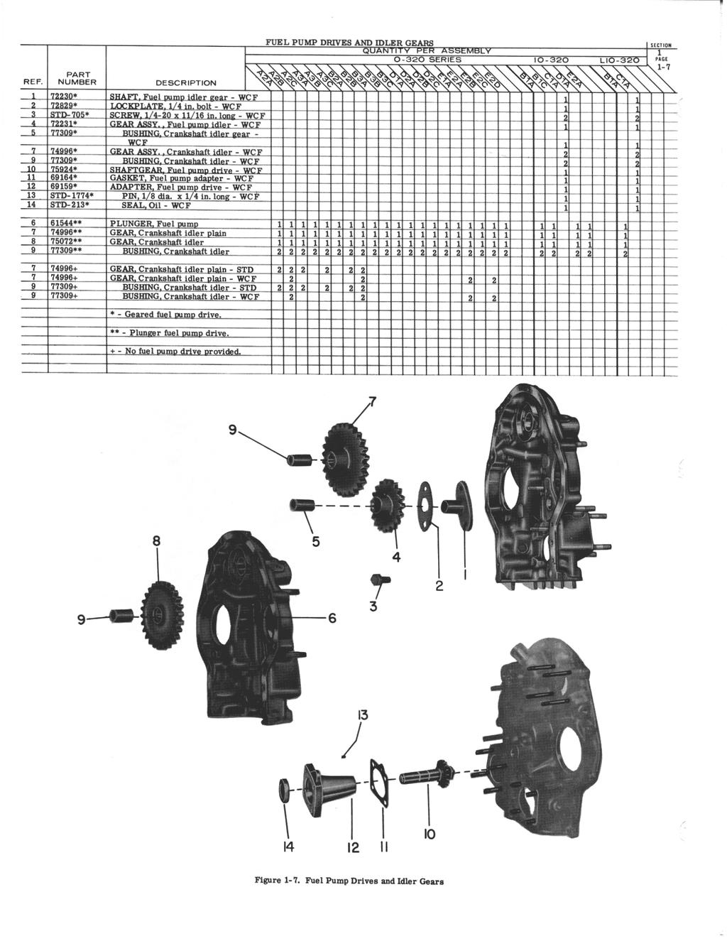
59 PART REF. NUMBER DESCRIPTION CRANKCASE ASSEMBLY SECTION QUANTITY PER ASSEMBLY 0-30 SERIES 0-30 LIO-30 PAGE 77* CRANKCASE ASSY. - STD 7* CRANKCASEASSY. -WCF 76* CRANKCASE ASSY. -STD 73** CRANKCASE ASSY. -WCF 70** CRANKCASE ASSY. - STD 7** CRANKCASE ASSY, -STD 706** CRANKCASE ASSY. - WCF 7+ CRANKCASE ASSY. - STD 7+ CRANKCASE ASSY. -WCF LW-05+ CRANKCASE ASSY. - WCF (Note ) LW-07+ CRANKCASE ASSY. - WCF LW-37+ CRANKCASE ASSY. - WCF (Note ) LW-305+ CRANKCASE ASSY. - WCF (Note ) LW-06** CRANKCASE ASSY. - WCF (Note 3) STD-557 DOWEL, /in. dia. x /6in. long STUD, /-3x9-/6 in. long-std 755 STUD, /-3x0-/3in. long-wcf 6673 STUD,/-3x9-7/ in.long-std STUD, /-3x9-/6 in. long- STD STUD, /-3x9-7/ in. long -STD STUD, /-3x0.0in. long-wcf 50- STUD, /-3x-3/in.long -STD 50-5 STUD, /-3x -7/ in. long-std 50-6 STUD, /-30x.00in. long-wcf B STUD, 3/-6x -/in. long STD STUD,3/-6x-5/in. long-std STUD, 3/-6x -3/in. long-wcf STUD, /-0x0-7/6in. long- STD STUD, /-0 x 0-/3 in.long- STD STUD, /-0 x 0-5/6 in. long- WCF DOWEL,Crankcase thru stud-wcf. STD-0 PLUG, /-7 NPT _ RETAINER,Shroud tube seal STUD,5/6-x-/in. long STUD,5/6-x -5/in. long DOWEL, Crankshaft bearing-wcf DOWEL, Crankshaft bearing - WCF DOWEL, Crankshaft bearing- WCF See Note ) _ LW-067 DOWEL, Crankshaft bearing - WCF. (See Note ) 6753 DOWEL, 6753 Crankshaft DOWEL, bearing - -STD STD STD-5 DOWEL,I 5/6 dia.x / in. long STD-63 INSERT,/-0 helicoil x 3/ in. 5 3D-7 STUD, 3/-6 x -/ in. long. I I STUD, 5/- x 5/6 in.long WCF -. _ NOZZLE ASSY, Piston cooling -WCF STUD -73# PLUG,/- NPT Allen 9 703* BUSHING,Engine support 0 STD-69* WASHER, Support bushing _ 637& SLEEVE, Oil relief valve * - Conical mounting. ** - Type dynafocal mountings. + - Type dynafocal mounting. -See Service Bulletin No # - For engines without governor drive. & For crankcase with no provision for adjustable oil pressure relief valve (Available in oversizep03). N O T E Crankcases LW-05 and LW-305 use 6976 crankshaft bearing dowels and LW-067 dowels. All others use dowels.. NOTE Crankcase LW-37 is no longer available. Order LW used this crankcase.see page -5 for attaching bolts 760 Ref. - use stud ea.and Ref.5 - use stud 3-3, 6 ea..
60 7 A Figure l-l. Crankcase Assembly
 - STD")
61 PART REF. NUMBER DESCRIPTION CRANKCASE RELATED PARTS QUANTITY PER ASSEMBLY O-30 SERIES 0-30 LIO-30 PAGE 677 BEARING, Crankshaft -STD 7703 BEARING, Crankshaft (when exhausted use LW-0) - STD BEARING,Crankshaft-STD LW-7703 BEARING, Crankshaft (when exhausted use LW-0) - BEARING,Crankshaft-WCF BEARING, Crankshaft LW-0 BEARING,Crankshaft Z BEARING, Crankshaft, front * 7690 SEAL Crankshaft, SEAL, Crankshaft oi oil l ** PLATE, Crankshaft oil seal (do not use with seal 5 STD-99** S SCREW,l-0x9/6in. long STD-60** WASHER / lock SEAL, Oil 090 section x 5/3 OD RING,Oil seal.._ BODY Hydraulic tappet 0 0B BALL,/6dia., oilpressure relief 666 SPRING Oilpressure relief valve STD-5+ WASHER No. 0 plain ARARARARARARARARARARAR RARARARARARARAR AAA 77+ PLUG, Oil relief valve STD-5 WASHER, No. 0 plain RARAARAARAR ARARARARA - 3STD-05 GASKET l PLUG Oil relief valve 6 770# VALVE ASSY. Oil pressure relief adjustable * - Use this seal when crankcase nose is not machined for six screw holes. ** - Use these parts when six screw holes are machined in crankcase nose. Instruc- + - Use these parts not machined in a/w Service tion No Use these parts for non-adjustable relief valve in crankcases machined in a/w Service Instructio No. 7, - For crankcase incorporating adjustable relief valve. NOTE Bearings are available in undersize M03,.M06 and M0. NOTE Bearings 7703 and LW-0 are available for IO-30-CIA and LIO-30- CA engines built with the stepped crankshaft dowel. NOTE Ref. 7 -Seal Crankcase LW- 06 (O-30-ED) uses only
62 Figure l-. Crankcase Related Parts I
 Note WCF A 750** CRANKSHAFT ASSY., (75007) Note - STD A 750** CRANKSHAFT ASSY., (75007) Note - B... 750+ WCF CRANKSHAFT ASSY., (7500) Note - STD B 750+ CRANKSHAFT ASSY.")
63 PART REF. NUMBER DESCRIPTION CRANKSHAFT ASSEMBLY QUANTITY PER ASSEMBLY 0-30 SERIES 0-30 LIO * CRANKSHAFT ASSY., (75006) Note - STD 7500* CRANKSHAFT ASSY., (75006) Note WCF A 750** CRANKSHAFT ASSY., (75007) Note - STD A 750** CRANKSHAFT ASSY., (75007) Note - B WCF CRANKSHAFT ASSY., (7500) Note - STD B 750+ CRANKSHAFT ASSY., (7500) Note - C WCF CRANKSHAFT ASSY., (7699) Note - ID WCF CRANKSHAFT ASSY., (769) Note - IE LW-096** WCF CRANKSHAFT ASSY., (LW- 095) See Note - WCF STD- PLUG,. 00in.dia.-Note " 3 STD-065 DOWEL, Stepped 7066# BUSHING, Propeller flange - STD 7066# BUSHING, Propeller flange - WCF 7065# BUSHING, Propeller flange - STD 7065# BUSHING,Propeller flange - WCF # BUSHING, Propeller flange -STD # BUSHING, Propeller flange - WCF # BUSHING, Propeller flange- STD # BUSHING, Propeller flange - WCF # BUSHING, Propeller flange (3 each) See Note # BUSHING, Propeller flange - WCF # BUSHING, Propeller flange - STD 6 706# BUSHING, Propeller flange -WCF 6 706# BUSHING, Propeller flange ( each) See Note PLUG, -3/in. OD - STD - Note PLUG, -3/in. OD -WCF-Note 7577 TUBE,Crankpin oil ( ea.) - Note. 3 Detail part of crankshafts and _GEAR, Crankshaft LOCKPLATE, Crankshaft gear STD-7 SCREW,5/6-x.00 in. long. * - Fixed pitch propeller,3/- thd. _ - Controllable pitch propeller 7/6-0 thread prop. bushings... + Controllable pitch propeller 7/6-0thread prop. bushings,two Short prop. bushings Available in oversize P05, P0 and NOTE -..- edgofedge age rderepla emen crankshaft by assembly number only. Use of these plugs is dependent on type application.see latest Service Instrction No. 09, Crankshafts, Part Number_6606,66. and 709 are no longer available. Detail parts are procurable. For location.of prop. flange bushings on engines fitted with these crankshafts, See illustration Ref. for 6606 and Ref. A for 66 and 709
64
65

66 PART REF. NUMBER DESCRIPTION 3 STD-0 BOLT, /-0x -3/ in. long WCF 3 STD-60 WASHER /ock-std 3 STD- 60 WASHER, / lock - WC F 3 STD- NUT, /-0 plain -STD 3 STD- NUT /-0 plain- WCF STD- 5 BOLT, /-0 x - / in. long- STD 5 STD- 9 BOLT /-0 x -/ in.long -WCF 5 STD- WASHER, / plain - WCF 5 STD-60 WASHER, / lock - WCF 6 STD-6 BOLT, /-0 x -/ in. long 3 6 STD- WASHER, / plain (maximum of 9) AR 6 STD-09 NUT, --0 slotted 3 7 STD-05 BOLT, 3/- x -3/6 in. long - STD 7 STD-33 WASHER, 3/plain- STD 7 STD-7 NUT, 3/- slotted- STD CRANKCASE ATTA( HING PARTS SECTION QUANTITY PER ASSEMBLY O-30 SERIES 0-30 LIO-30 PAGE -5 STD-97 BOLT, 3/-x 3-/ in. long STD-33 WASHER, 3/ plain - STD ~ STD-33 WASHER, 3/ plain plain- WCF STD-67 WASHER, 3/ l lock STD-596 NUT, 3/- plain STD- BOLT, /-0 x -/ in. long a a a th STD- WASHER / plain STD-60 WASHER, / lock STD- NUT, /-0 plain 3 STD-0 BOLT /-0 x -3/ in. long- STD STD-7 - WCF STD-33 - WCF STRAP, Lifting - 0 STD- 090 NUT, /- 0 plain (thru bolt at nose of crankcase) - WCF SPACER, 33/6 IDx 7/ in. OD BOLT, /-0 x 0. 7 in. long - WCF 760 BOLT, /-0 x 0. 7 in. long STANDARD CRANKCASE WIDE CYLINDER FLANGE CRANKCASE Figure -5. Crankcase Attaching Parts

67 SUPPORT ASSEMBLY AND IDLER SHAFTS SECTIO QUANTITY PER ASSEMBLY 0-30 SERIES IO-30 LIO-30 PAGE REF. NUMBER DESCRIPTION 667 SUPPORT ASSY, Starter ring gear 0/ pitch,. 9: drive - STD 667 SUPPORT ASSY., Starter ring gear 0/ pitch,. 9: drive - WCF 69* SUPPORT ASSY. Starter ring gear 0/ pitch, drive.9: - STD 7 SUPPORT ASSY., Starter ring gear / pitch,.9:drive -STD 7 SUPPORT ASSY., Starter ring gear / pitch,.9:l drive- WCF 766 SUPPORT ASSY., Starter ring gear / pitch, 3.5: alt. drive- WCF 7699 SUPPORT ASSY. Starter ring gear 0/ pitch, 3.5: alt. drive - WCF 769 SUPPORT ASSY., Starter ring gear pitch, 3.5: drive - WCF LW-055 SUPPORT ASSY.,Starter ring gear / pitch. 3. 5: alt.drive-wcf 60 GEAR,Starter ring 0/ pitch 7566 GEAR,Starter ring / pitch LW- 055 GEAR, Starter ring / pitch ** SPACER, Propeller hub STD FLANGE, Propeller - STD 5 STD-33+ WASHER,3/ plain - STD STD-9+ BOLT, 3/- x. long - STD GEAR. Camshaft 6757 SHAFT, Tachometer 9 STD-99 PIN 3/6 dia. i llllll SLINGER, Breather 707 LOCKPLATE 5/6 bolt 3 STD- 79 BOLT. 5/6- x 66 long 76# SHAFT. Tachometer 9 736# PIN, 3/6 x. 33 in.long 0 76# SPACER, Tach. shaft. MS665- RING, Internal retaining 0* SHAFT, Crankshaft idler - WCF LOCKPLATE, 5/6 bolt - WCF 7 STD- 96 BOLT, 5/6- x. 67 long - WCF 3 3 STD- 0 NUT, 5/6- plain - WCF SHAFT, Crankshaft idler - STD LOCKPLATE, / in. bolt - STD 7 STD-705 SCREW, /-0 x.69 long - STD * - Less spinner holes. ** - Required when no starter ring gear support is used. + - For fixed pitch installation only. - Use on all engines incorporating removable camshaft gear. * - Use on all engines incorporating integral camshaft and gear. NOTE 0/ pitch ring gears have teeth. / pitch ring gears have 9 teeth. See latest Service Instruction No. and.
68
69 I
70 LYCOMING AIRCRAFT ENGINE GROUP ASSEMBLY PARTS LIST. 3 0 U J LYCOMING PARTS CATALOG 0-30, 0-30 AND LIO-30 SERIES SECTION ACCESSORY HOUSING AND DRIVES

71 75 STUD, /-0 - in. long 3 75 STUD, /-0 x -/ in. long 63 STUD, /-0 x. 7 in. long 6970 STUD, /-0 x 3-7/ in. long 5 63 STUD, /-0 x. 7 in. long STUD, /-0 x -3/ in. long 6 66 STUD, 5/6- x -/ in. long STUD, 5/6- x -5/ in. long 7 66 STUD. 5/6- x -/ in. long STUD, 5/6- x - 3/ in. long
72
 ACCESSORY HSG., (Two impulse SLN- magnetos) ACCESSORY HSG.")
73 REF PART NUMBER 766* 763** 7697 LW LW- 050 LW- 65+ ACCESSORY HOUSING - INTEGRAL CAM GEAR SECTI ON QUANTITY PER ASSEMBLY PA 0-30 SERIES 0-30 LIO-30 DESCRIPTION GASKET, Accessory housing ACCESSORY HSG., (Plain SLN-0 and impulse SLN- magneto) ACCESSORY HSG., (Two impulse SLN- magnetos) ACCESSORY HSG., (Plain SLN-0 and impulse SLN- magneto, vacuum and hyd. dual drive) - STD ACCESSORY HSG., (Plain SLN-0 and impulse SLN- magneto, vacuum and hyd. dual drive) - WCF ACCESSORY HSG., (Plain SLN-0 and impulse SLN- magneto, vacuum and prop, gov. dual drive) - STD ACCESSORY HSG., (Plain SLN-0 and impulse SLN- magneto, vacuum and prop. gov. dual drive) - WCF ACCESSORY HSG., (SLN-00 and SLN-0 magneto) - STD ACCESSORY HSG., (SLN-00 and SLN-0 magneto, vacuum and hyd. dual drive) ACCESSORY HSG., (Plain SLN-0 and impulse SLN- mag. ) ACCESSORY HSG., (SLN-00 and SLN-0 magneto) ACCESSORY HSG., (Two impulse SLN- magnetos) ACCESSORY HSG., (Two impulse SLN- magnetos) ACCESSORY HSG., (Plain SLN-0 and impulse SLN- magneto) ACCESSORY HSG., (Machined for vacuum pump pad and fuel pump pad, gov- ernor pad un-machined) ACCESSORY HSG., (Two impulse SLN- magnetos) ACCESSORY HSG., (Two impulse SRN- magnetos) ACCESSORY HSG., (Two impulse SRN- magnetos) ACCESSORY HOUSING PART NUMBER ACCESSORY HOUSING RELATED PARTS: CD- STD-0 3 STD-7 STD C-3 6 3C-0 7 STD STD STUD, /-0 x.9 in long STUD, /- 0 x -/ in.long STUD, /-0 x l-/ in. long STUD, /-0 x.7 in long STUD, /-0 x 3-7/ in. long 3 3 STUD, /-0x.7 in. long STUD, /-0 x -3/ in. long STUD, 5/6-x-/in. long STUD, 5/6- x -5/ in. long STUD, 5/6-x -/ in. long STUD, 5/6- x -3/ in. long STUD,5/6- x-3/ in. long STUD, 5/6- x -/ in. long STUD, 5/6- x / in. long STUD, 5/6- x.9in. long STUD, 5/6- x.9 in. long STUD, 5/6- x -3/ in. long PLUG, /-7 NPT, Allen PLUG, 3/- NPT, Allen PLUG, /-7 NPT, Allen TUBE, Accessory breather STUD, 5/6- x -3/ in. long SUTD, 5/6- x5 in. long RING, Oil seal PLUG, 5/ ODx 3/ in. long PLUG, /- NPT, Allen SHIELD, Accessory breather, oil * - Long studs at fuel pump pad. ** - Standard cylinder flange only (IO- 30- BA). + - Long studs at fuel pump pad for pump and spacer.
74

75 OIL PUMP AND ACCESSORY HOUSING ATTACHING PARTS S QUANTITY PER ASSEMBLY 0-30 SERIES 0-30 LIO-30 PAGE -3 PART DESCRIPTION - REF. NUMBER DESCRIPTION 7635 BODYASSY.,Oil pump LW- 09 BODY ASSY., Oil pump 6039 SHAFT 6039 pump idler SHAFT Oil pump idler STD-7 PIN,.3dia. x.00 long, AN30C- PIN, 3 dia. x / in. long.3 STD-339 PLUG,/6-7 NPT, Allen 67 SHAFT, Oil pump drive IMPELLER, Oilpump, driving IMPELLER, Oil pump, driven 7 STD-35 WASHER, 5/6plain STD-0 NUT, STD- 5/6-0 slotted -MT, slotted 5/ STD- 7 WASHER, / in, copper STD-90 BOLT, /-0 x -3/ in. long STD- WASHER, / plain STD-09 NUT, /-0 slotted SEAL, Tachometer drive,oil ACCESSORY HOUSING - ATTACHING PARTS: 0 STD WASHER, / plain STD-60 WASHER, / STD- 0 / BOLT, -0x 5/6 lo in. long STD-0 BOLT, /-0 STD-60 WASHER / lock STD- STD- BOLT, BOLT, /-0 /-0 x - -/ / in. long -
76

77 PART REF. NUMBER DESCRIPTION OIL COOLER AND FILTER SECTION QUANTITY PER ASSEMBLY O-30 SERIES 0-30 LIO-30 PAGE HOUSING Oilpressure screen 65* HOUSING,Oil pressure screen 6950 HOUSING, Thermostatic valve and oil pressurescreen 673 GASKET, Oil pressure housing 67 SCREEN ASSY,Oil. pressure 5 STD-9 GASKET,. OD x.63 ID 5 STD-9* GASKET,. OD x. 63 ID 6 STD- WASHER, / plain 6 STD- ** WASHER, / plain STD- SCREW, /-0 x.00 in.long 7 STD-* SCREW,/-0 x.00 in.long 3 7. STD- 56 SCREW, /-0 x /-0x.00 in.(capscrew) oil cooler bypass GASKET, Temp.control valve I I KIT,Oil filter and adapter 7669 GASKET Filter and adapter l 6360 NUT, Nylon GASKET Rubber GASKET, Rubber FILTER ASSEMBLY ll l GASKET, Copper STUD, Center 5C0-P03 STUD, /-0 x -/in.long 9 STD- NUT,/-0 plain 0 STD-60 WASHER, / lock STD- WASHER, / plain STD-56 SCREW, /-0,self-locking PLUG, Oil cooler by pass ii STD-9 GASKET, Oil cooler by pass plug SPRING,Oil cooler byass 6 65 PLUNGER, Oil cooler bypass CONNECTOR,Accessory housing to oil cooler inlet hose STD-9 GASKET,. OD x.63 ID ll BOLT, Oil cooler fitting 30 AN90-A GASKET, Metal tube connection seal 3 AN777-D ELBOW, Universal, WASHER, Oil cooler fitting 33 AN-0D E LBOW, Pipe thread, 5/ in. ID hose, 5 (Piper) 3 70 FITTING, Breather, straight (in accessory housing) 3 73 FITTING, Breather,0 elbow, (in accessory housing -Beech) *- Speial thermometer connection in oil pressure screen housing ** - Screws to attach thermostatic housing for engines equipped with vacuum and hydraulic pump or vacuum and prop. governor dual drive. - Not required when thermostatic oil bypass valve is used. + - See latest Service Letter No.
78

79 REF PART NUMBER * STD-77* STD-0* 7970* 7596* VACUUM PUMP DRIVE ADAPTER AND DUAL DRIVES SECTION QUANTITY PER ASSEMBLY 0-30 SERIES 0-30 LIO-30 PAGE -5 DESCRIPTION GASKET, Accessory adapter ADAPTER ASSY.,Vacuum pump PIN, / dia.x / in. long OIL SEAL GEAR ASSY.,Vacuum pump driven WASHER, Accessory driven gear ** DUAL DRIVE ASSY., Vacuum pump and hydraulic pump DUAL DRIVE ASSY., Vacuum pump # and prop. governor drive 6975 ADAPTER ASSY., Dual accy. drive 9 66 STUD, /-0x. 53 in. long STUD, /-0x3.63 in. long DOWEL, / dia. x / in. long' 6939 GEAR ASSY., Accessory drive WASHER, Accy. drive gear STD-07 "O" RING, Static seal 6936 GEAR, Dual drive GEAR ASSY., Accessory idler BUSHING, Accy. idler gear WASHER, Accessory driven gear 733 GEAR, Vacuum pump driven GASKET, Dual drive adapter cover 0 697** COVER ASSY., Vacuum hyd. drive COVER ASSY.,.Vacuum and prop. governor adapter STD-0 SEAL, Oil STD-5** SEAL, Oil 3 699** STUD, /-0 x. 53 in. long 699+ STUD, /-0 x.53 in. long STUD, /-0 x. 9 in. long SHAFT, Accessory idler 7 STD-93 DOWEL,. 09 dia. x. 3 long STD- 339 PLUG, /6-7 NPT, Alien 9 STD- 0+ PLUG, /-7 NPT, Allen 9 STD-339** PLUG, /6-7 NPT, Allen 30 STD-77+ PIN, / dia. x / in. long 3 STD- WASHER, / plain 3 STD-60 WASHER, / lock 33 STD- NUT, /-0, plain 3 STD-?9 WASHER, / plain 35 STD- 60 WASHER, / lock 36 STD- NUT, /-0 plain 37 STD-+ WASHER, / plain STD-60+ WASHER, / lock CAPSCREW STD-696 WASHER,. 7 ID x / in. OD AR ARAR AR 703 BRACE, Dual drive support STD-60 WASHER, / lock _ 3 STD-5 BOLT, /-0 x -/ in. long 697+ GASKET, Governor spacer I SPACER, Governor * - Vaccuum pump only. ** - Vacuum pump and hydraulic pump dual drive. + -Vacuum pump and propeller governor dual drive. - Dual drive (either hydraulic pump or propeller governor)... #- Standard cylinder flange only.
80

81 REF. PART NUMBER 33* 33** 6030* 6030** 3 STD- * 3 STD-** STD- 60* STD- 60** 5 STD- * 5 STD- ** DESCRIPTION GASKET, Vacuum and hyd. pump GASKET, Vacuum pump COVER, Vacuum and hyd. pump COVER, Vacuum pump WASHER, / plain WASHER, / plain WASHER, / lock WASHER, / lock NUT, /-0 plain NUT, /-0 plain PROPELLER GOVERNOR DRIVE AND COVERS QUANTITY PER ASSEMBLY 0-30 SERIES 0-30 LIO-30 SECTION PAGE ** 9 STD- 0 STD- 60 STD- 33 GASKET, Accessory adapter COVER, Vacuum pump SPACER, Vacuum pump stud WASHER, / plain WASHER, / lock NUT, /-0 plain GASKET, Vacuum pump # # # # # 3 69-C STD-35 6 STD-75 7 STD- 0 GASKET, AN fuel pump drive COVER, AN fuel pump drive WASHER, 5/6 plain WASHER, 5/6 lock NUT, 5/6- plain STD-33 STD- 59 GASKET, Fuel pump COVER, Fuel pump drive (diaphragm) WASHER, 3/ plain BOLT, 3/-6 x 3/ in. long STD-+ SHAFTGEAR, Prop. governor drive WASHER, Accessory driven gear RING, 3/6 dia. x.0 thick * - Dual drive. ** - Vacuum pump - no dual drive. + - Propeller governor drive parts. - Wide cylinder flange only. # - Standard cylinder flange only.
82

83 PROPELLER GOVERNOR ADAPTER AND COVERS SECTION QUANTITY PER ASSEMBLY 0-30 SERIES I0-30 LIO-30 PAGE PART REF. NUMBER DESCRIPTION 7553* ADAPTER ASSY., Prop. governor drive - STD 7553* ADAPTER ASSY., Prop. governor driv e - WCF 7555** ADAPTER ASSY., Prop. governor 7555** drive-std 7555** ADAPTER ASSY.,Prop. governor drive - WCF 757+ _ ADAPTER ASSY. Prop. governor drive - STD 635 GASKET,Accy. drive adapter I 3 STD-0 PLUG /NPT, Allen STUD, 5/6- xin.long(usein 7553 or 757) 636 _ STUD, 5/6-x-/6 in. long (use in 7555) 5 STD-77 PIN, / dia.x /in.lon g 6 STD-35 WASHER, 5/6 plain 7 STD-75 WASHER,5/6 lock STD-0 NUT, 5/6- plain GAS, Governor drive STD-35 WASHER, 5/6 plain STD-75 WASHER, 5/6 lock 3 STD-0. NUT, 5/6- plain 737# COVER, Governor drive adapter -STD 737# COVER, Governor drive adapter -WCF # GASKET, Governor 6 STD-35* WASHER,5/6 plain STD-35** WASHER, 5/6 plain 7 STD-75 WASHER,5/6 lock STD 0 NUT 5/6 - plain STD-73 PLUG, /- NPT, Allen (right crankcase -front) - Wooward * governor. * - Woodward governor. ** - AN governor +- AN governor - Colonial installation. - Use these parts when no prop. governoror adapter is used. # -Use this cover and gasket when required.
84 Figure -7. Propeller Governor Adapter and Covers -

85 PART REF. NUMBER DESCRIPTION SUMP ASSEMBLY SECTION QUANTITY PER ASSEMBLY 0-30 SERIES 0-30 LIO-30 PAGE GASKET, Oil sump 69370* SUMP ASSEMBLY, Oil - STD 69370* SUMP ASSEMBLY, Oil WCF 736** SUMP ASSEMBLY, Oil - STD 736** SUMP ASSEMBLY,Oil - WCF SUMP ASSEMBLY, Oil - WCF CONNECTION, Intake pipe, front 6377 CONNECTION, Intake pipe, rear STUD, 5/6- l-7/ x in. long 6 STD-55 PLUG, /- NPT,square hd. STD-0 BOLT, /-0 x 5/6 in. long STD- WASHER,/ plain 7 STD-60 WASHER, / lock STD- NUT, /-0 plain STD- WASHER, / plain STD-60 WASHER, / lock 9 STD-0 BOLT, /-0 x 5/6 in. long 9 STD 60 WASHER,/ plain 9 STD- 60 WASHER / lock 9 STD- NUT, /-0 plain GASKET Oil suction TUBE ASSY. tube STD-7 WASHER, / plain, copper 3 STD-33 BOLT,/-0 x / in. long STD- WASHER, / plain(max.) ARAARAARARARARAARA A 5 STD-09 NUT, /-0 slotted 6 STD-6 PIN,/6 dia.x / long SCREEN Oil suction STD- 05 GASKET, - /ID x ID x -/ in. OD PLUG, -/in. hex.hd. - x thd. lxl-/ 0 65 NAMEPLATE STD-90 DRIVE STUD No. x. 9 in. long * - Large inlet chamfer. Use carburetor ** - Straight riser. Use carburetor 739. or injector injector 7760.
86

87 PART REF. NUMBER DESCRIPTION SUMP ASSEMBLY SECTION QUANTITY PER ASSEMBLY 0-30 SERIES 0-30 LIO-30 PAGE GASKET, Oil sump 703* SUMP ASSEMBLY, Oil - STD 703* SUMP ASSEMBLY, Oil -WCF LW-075** SUMP ASSEMBLY, Oil - WCF SUMP ASSEMBLY, Oil SUMP ASSEMBLY, Oil 70 CONNECTION, Intake pipe CONNECTION, Intake pipe STUD, /-0 x -3/6in. long STUD, 5/6- x -7/ n. long 66 STUD, 5/6- x -/ in. long 650 STUD, 5/6- x 3.3 in. long 9 STD-55 PLUG, /- NPT, square head 0 STD-9 PLUG, /- NPT, Allen STD-0 PLUG, /-7 NPT, Allen STD-0 BOLT, /-0x5/6in. long STD- WASHER, / plain STD-60 WASHER, / lock 3 STD- WASHER, / plain - STD only STD- NUT, /-0 plain STD-60 WASHER, / lock STD- WASHER, / plain STD-0 BOLT, /-0 x 5/6 in. long 5 STD- WASHER, / plain STD-60 WASHER, / lock 5 STD- NUT,/-0 plain 6 70 SCREEN, Oil suction 7 STD- GASKET,.00 ID x-/in. OD PLUG, 5/in.hex. x th NAMEPLATE 0 STD-90 DRIVE STUD, No. x.9 long *-Dynafocal mounting. For use with - **- Dynafocal mounting. For use with injector. + - Rear inlet fuel injection.
88 I
89 LYCOMING AIRCRAFT ENGINE GROUP ASSEMBLY PARTS LIST LYCOMING PARTS CATALOG 0-30, 0-30 AND LIO-30 SERIES SECTION 3 CYLINDER, PISTON AND VALVE TRAIN
90 LYCOMING AIRCRAFT ENGINE GROUP ASSEMBLY PARTS LIST with this cylinder on this model use this piston with this top ring this nd ring and this this this service oil exhaust intake with ring valve valve this kit 70C O-30-A,-E 70C 0-30-A,-E 7P 0-30-A,-E 7P O-30-A,-E 7P 0-30-B,-D 7P O-30-B,-D 7969C 0-30-B,-D 7969C 0-30-B,-D 739N 0-30-B,-D 76N IO-30-BA 750N* 0-30-B, -D and LIO-30-B IO-30-B, -D 750N* 0-30-EA,-EC IO-30-EA 750N* 0-30-B,-D 753C O-30-A,-E 753C O-30-A,-E 75P 0-30-A,-E 75P 0-30-A,-E 75C O-30-B,-D 75C 0-30-B,-D 7537P* O-30-A,-E 7536N 0-30-B,-D 756P* O-30-A,-E 756P* O-30-A,-E 75907C* O-30-A,-E 75907C* 0-30-B,-D 75907C O-30-A,-E 7606N* IO-30-CA and LIO-30-CA 7776P 0-30-B,-D 7776P 0-30-B,-D 755C* 0-30-AB * - Wide Cylinder Flange. C - Chrome P - Plain N - Nitrided FW - Full Wedge Rings FW FW 759FW FW None 7393 None 7393 None 7393 None 7393 None 7393 None 7393 None 7393 None 7393 None FW 7059FW FW FW FW None None None None None None None See Note See Note See Note See Note See Note See Note NOTE: Piston P/N 7059 and P/N 753 are interchangeable singly or in sets - with proper ring combination. Piston 7059 is no longer available. Pistons and rings are available in oversize P0 and P0, for use in plain cylinder barrels only. See latest edition of Service Instruction No /6" exhaust valves are no longer available. See latest edition of Service Instruction No
91 LYCOMING AIRCRAFT ENGINE GROUP ASSEMBLY PARTS LIST O-30,0-30, LIO-30 SERIES 3-l - PISTON AND RINGS See chart PISTON see chart opposite for RING, Piston, top opposite for 3 part RING, Piston, nd model numbers RING, Piston, oil regulating application. 5* 7757 PIN, Piston (heavy) PIN, Piston PLUG, Piston pin - use with plain or nitrided cylinder assemblies PLUG, Piston pin - we with chrome cylinder assemblies * A and -E (low compression) only. 6 Figure 3-. Piston and Rings
- WCF CYLINDER ASSY., Chrome (supersedes 70)- STD CYLINDER ASSY., Plain (supersedes 7) - STD CYLINDER ASSY., Chrome (supersedes 7969) - STD CYLINDER ASSY.")
92 REF PARTT NUMBER CYLINDER ASSEMBLY SECTION QUANTITY PER ASSEMBLY SERIES 0-30 LIO-30 PAGE 3- DESCRIPTION CYLINDER ASSY., Nitrided - STD CYLINDER ASSY., Nitrided (supersedes 750)- WCF CYLINDER ASSY., Chrome (supersedes 70)- STD CYLINDER ASSY., Plain (supersedes 7) - STD CYLINDER ASSY., Chrome (supersedes 7969) - STD CYLINDER ASSY., Nitrided (supersedes 739 and 7) - STD) CYLINDER ASSY., Plain (supersedes 7537)- WCF CYLINDER ASSY., Chrome (supersedes 755) - WCF CYLINDER ASSY., Nitrided - WCF * SEAT, Intake valve 705* SEAT, Exhaust valve 600** GUIDE, Intake valve 730** GUIDE, Exhaust valve - See Note P0 INSERT,Spark plug (short reach) 6960-P0 INSERT, Sparkplug (long reach 66 STUD, 5/6- x -/ in. long STD- 7 INSERT, /-7 helicoil - WCF STD-7 INSERT, /-7 helicoil - STD STD-7 INSERT, /-7 helicoil- WCF 650 STUD, /-0 x.06 long AN3-6D ELBOW,5,3/ flared tube BUSHING, Rocker shaft 6 STD- 0 PLUG, /-7 NPT, Allen.. _ * - Available in oversize P0,P0 and P30. ** - Available in oversize P05,P0 and P Available in oversize P05 and P0, - Installed in primer holes and injector tube holes when primer lines and injector tubes are not installed. _ NOTE 730 exhaust valve guide supersedes guide which is available at Avco Lycoming for those engines still equipped with 7/6 inch exhaust valves guide is available in oversize P05 and P 0.
93 I 6 7 I II Figure 3-. Cylinder Assembly

94 VALVES AND PLUNGERS SECTION QUANTITY PER ASSEMBLY 3 O-30 SERIES 0-30 LIO-30 PART REF. NUMBER DESCRIPTION 7393 VALVE, Intake 7506* VALVE, Exhaust 75* VALVE, Exhaust 760* VALVE, Exhaust, inconel SPRING, Valve, inner 7699 SPRING, Valve, outer 5 65 SEAT, Valve spring, lower,intake SEAT, Valve spring, lower, exhaust 7 LW SEAT, Valve spring, upper, intake LW-0076 SEAT, Valve spring, upper, exhaust KEY, Valve, intake 0 MS KEY, Valve, exhaust MS399-3 CAP, Valve stem, exhaust 790 PLUNGER ASSY., Hyd. tappet SOCKET, Push rod, hyd. tappet 7577 TUBE, Push rod, shroud SPACER, Shroud tube spring SPRING, Shroud tube 7 65 LOCKPLATE, Shroud tube STD- NUT, /-0plain SEAL, Shroud tube SEAL, Shroud tube * These are / inch valves.the.7/6 inch exhaust valves are no longer available. Presently installed 7/6 inch exhaust valves must be serviced with the following related parts which are available from Avco Lycoming SEAT,Valve spring,lower exhaust 6953 SEAT,Valve spring,upper exhaust KEY, Valve, exhaust 63 CAP, Valve stem, exhaust
95 Figure 3-3. Valves and Plungers

96 ROCKERS, PUSH RODS, INTAKE PIPES AND OIL DRAIN TUBES

97 IO 5 Figure 3-. Rockers, Push Rods, Intake Pipes and Oil Drain Tubes
98 LYCOMING AIRCRAFT ENGINE GROUP ASSEMBLY PARTS LIST " LYCOMING PARTS CATALOG 0-30, IO-30 AND LIO-30 SERIES SECTION IGNITION SYSTEM
99 6 6 3
100

101 CABLE ASSEMBLY. IGNITION. SHIELDED AVCO LYCOMING 5MM QUANTITY PER ASSEMBLY REF. PART NUMBER LW- 039 LW-039 LW-0390 LW- 039 LW DESCRIPTION CABLE ASSY., Ignition shielded, 5mm - STD CABLE ASSY., Ignition shielded, 5mm - WCF CABLE ASSY., Ignition shielded, 5mm, ightweight - STD CABLE ASSY., Ignition shielded, 5mm, lightweight - WCF CABLE ASSY., Ignition shielded, 5mm, (colonial) - STD CABLE ASSY., Ignition shielded, 5mm, 00 series magnetos - WCF CABLE ASSY., Ignition shielded, 5mm - STD CABLE ASSY., Ignition shielded, 5mm - WCF PLUG, Grommet COLLAR, Silicone NUT, 5/- ELBOW, 70' (for 7539) ELBOW, 70, bottom (for 750 and 756) ELBOW, 90 top (for 750 and 756) ELBOW, 70 (for 75 and 757) 6 ELBOW, 0 (for 75 and 757) Length Elb ows in. 7 in. Silicone Insulation Example: S 0 63 Spark Plug Nut See Service Instruction No SLEEVING RING, Plastic PLATE, Spark plug cable LW-000 FERRULE, Braid retaining SLEEVEShield 0 LW-3 SPACER, Magneto grommet 765 GROMMET, Magneto GROMMET, Magneto 735 EYELET,Hi-tension 6 6
102 5 Figure -3. Shielded Ignition Cable - Avco Lycoming 5MM

103 PART REF NUMBER DESCRIPTION LW HARNESS ASSY., Ignition, Scintilla, -00 series magnetos LEAD ASSY.,Cyl. no. lb LEAD ASSY., Cyl. no. 3B LEAD ASSY., Cyl. no. T LEAD ASSY., Cyl. no. 3T LEAD ASSY., Cyl. no. B LEAD ASSY., Cyl. no. B LEAD ASSY., Cyl. no. T LEAD ASSY., Cyl. no. T PLATE GROMMET FERRULE EYELET CABLE TIE CLAMP SCREW SCREW NUT BRACKET PLATE GROMMET CLAMP CLAMP CLAMP CLAMP TUBING Spiral BRACKET CLAMP CLAMP HARNESS ASSEMBLY, SCINTILLA, -00 SERIES MAGNETOS SECTION QUANTITY PER ASSEMBLY 0-30 SE RIES 0-30 LIO-30 PAGE STD- 95 SCREW, /- 0 x 5 in. long STD-96 SCREW, /-0 x. 3 in.long STD- 60 WASHER, / lock STD- NUT, /-0 plain STD- 7 SCREW, /-0x7/ in.long 039 PROTECTOR,Ignition cable (top!leads 3
104 Figure -. Harness Assembly, Scintilla -00 Series Magnet

105 PART REF. NUMBER DESCRIPTION HARNESS ASSEMBLY. IGNITION, SCINTILLA, -00 SERIES MAGNETOS SECTION QUANTITY PER ASSEMBLY 0-30 SERIES 0-30 LIO-30 PAGE LW HARNESS ASSY., Ignition, Scintilla, -00 series magnetos LEAD ASSY., Cyl. no. B LEAD ASSY., Cyl. no. 3B LEAD ASSY., Cyl. no. T LEAD ASSY.,Cyl. no. 3T LEAD ASSY., Cyl. no. T LEAD ASSY., Cyl. no. T LEAD ASSY.,Cyl. no. B LEAD ASSY., Cyl. no. B SCREW NUT CLAMP CLAMP CLAMP TUBING, Spiral CLAMP GROMMET PLATE CLAMP SCREW NUT BRACKET FERRULE EYELET CLAMP SCREW TIE, Cable CLAMP L 735 SCREW, No. 0-3 self-locking STD- 7 SCREW, /-0 x 7/ in long PROTECTOR, SPRING Ignition cable (top leads) SLEEVE
106 Figure -5. Harness Assembly, Scintilla -00 Series Magneto
107 Figure -6. Harness Assembly, Ignition, Slick
108
109 LYCOMING AIRCRAFT ENGINE GROUP ASSEMBLY PARTS LIST 0 LYCOMING PARTS CATALOG 0-30, I0-30 AND LIO-30 SERIES SECTION 5 ELECTRICAL SYSTEM
110
111 . -d Figure 5-. Generator/Alternator Bracket - Std. Cylinder Flange Engines

112 -_-- - ^ **- For V-0Aand'V-50A'genera- -- _' tors only.
113 Figure 5-. Generator/Alternator Bracket - Wide Cylinder Flange Engines

114 PART REF. NUMBER DESCRIPTION GENERATOR AND ALTERNATOR SECTION QUANTITY PER ASSEMBLY 0-30 SERIES 0-30 LIO-30 PAGE * GENERATOR, V-0A, Delco-Remy ** GENERATOR, V-35A,Delco-Remy GENERATOR,V-5A,Delco-Remy 090 (use bracket 695)- STD 77+ GENERATOR, V-50A, Delco-Remy GENERATOR, V-0A,Delco-Remy (use bracket 709)-WCF GENERATOR, V- 50A, Delco-Remy (use bracket 709) 739 ALTERNATOR, V-70A,Delco-Remy 0077 (Note ) 76 ALTERNATOR,V-50A,Delco-Remy 007 (Note ) l L ALTERNATOR, V-0A, Prestolite ALE-05A (usebracket76533) -WCF 730 ALTERNATOR, V-0A, Prestolite ALE-06 (usebracket76533)-wcf 7309 ALTERNATOR, V-70A, Prestolite ALX-03- WCF 73 ALTERNATOR, V-50A, Prestolite ALT-0 (use bracket 76533)-WCF 73 ALTERNATOR, V-70A, Prestolite ALU-03 - WCF l l 709 ALTERNATOR,V-0A, Prestolite ALE ALTERNATOR, V-50A,Prestolite ALZ-0(use bracket 76533) 7059 ALTERNATOR, V-50A Prestolite EO-00 LB(Note 3) 707 ALTERNATOR,V-60A, Prestolite ALY-03 - WCF 709 ALTERNATOR, V-60APrestolite ALY-603 (Note 3) LW-037 ALTERNATOR, V-60A, Prestolite ALY-05 LW-076# ALTERNATOR, V-0A, Prestolite ALE-0 (Note 3) l LW-3959# ALTERNATOR, V-50A Prestolite LW-395 EO-0950(Note3). LW-396# ALTERNATOR, V-60A,Prestolite EO-095(Note 3) l 70 ALTERNATOR ASSEMBLY,V-70A, Delco-Remy (Note ) 750 ALTERNATOR ASSEMBLY, V-50A, Delco-Remy (Note ) PULLEY, Alternator, 3.5: l 77 FAN & BAFFLE ASSEMBLY 7 EXTENSION ASSEMBLY,Alternator output terminal (for Prestolite when required)... * - Use bracket 693 for standard cylinder flange or 709 for wide cylinder flange. ** - Use bracket 695 for standard cylinder flange or 709 for wide cyl inder flange Use bracket 695, 709 or 75 and Use non-adjustable bracket or adjustable brackets and For single engine installation Wico regulator P/N LW-357. use.. NOTE Part of 70 Alternator Assembly NOTE Part of 750 Alternator Assembly. NOTE.3 Parts for these alternators may be ob tained direct from Prestolite

115 3 Figure 5-3. Generator and Alternator

116

117 PART REF. NUMBER DESCRIPTION VOLTAGE REGULATOR AND RELAY QUANTITY PER ASSEMBLY 0-30 SERIES 0-30 LIO REGULATOR, Voltage, V- 35A, nonparalleling, Delco-Remy REGULATOR, Voltage, V- 35A, paralling, Delco-Remy REGULATOR, Voltage, V-5A, nonparalleling, Delco-Remy REGULATOR, Voltage, V-5A, paralling, Delco-Remy REGULATOR, Voltage, V-50A, nonparalleling, Delco-Remy REGULATOR, Voltage, V- 50A, paralleling, Delco-Remy REGULATOR, Voltage, V-0A, nonparalleling, Delco-Remy REGULATOR, Voltage, V-70A, Full transistor, Delco-Remy i LW-079 REGULATOR, Voltage, V, Full tran-
118 LYCOMING AIRCRAFT ENGINE GROUP ASSEMBLY PARTS LIST LYCOMING PARTS CATALOG 0-30, IO-30 AND LIO-30 SERIES SECTION 6 FUEL INDUCTION SYSTEM
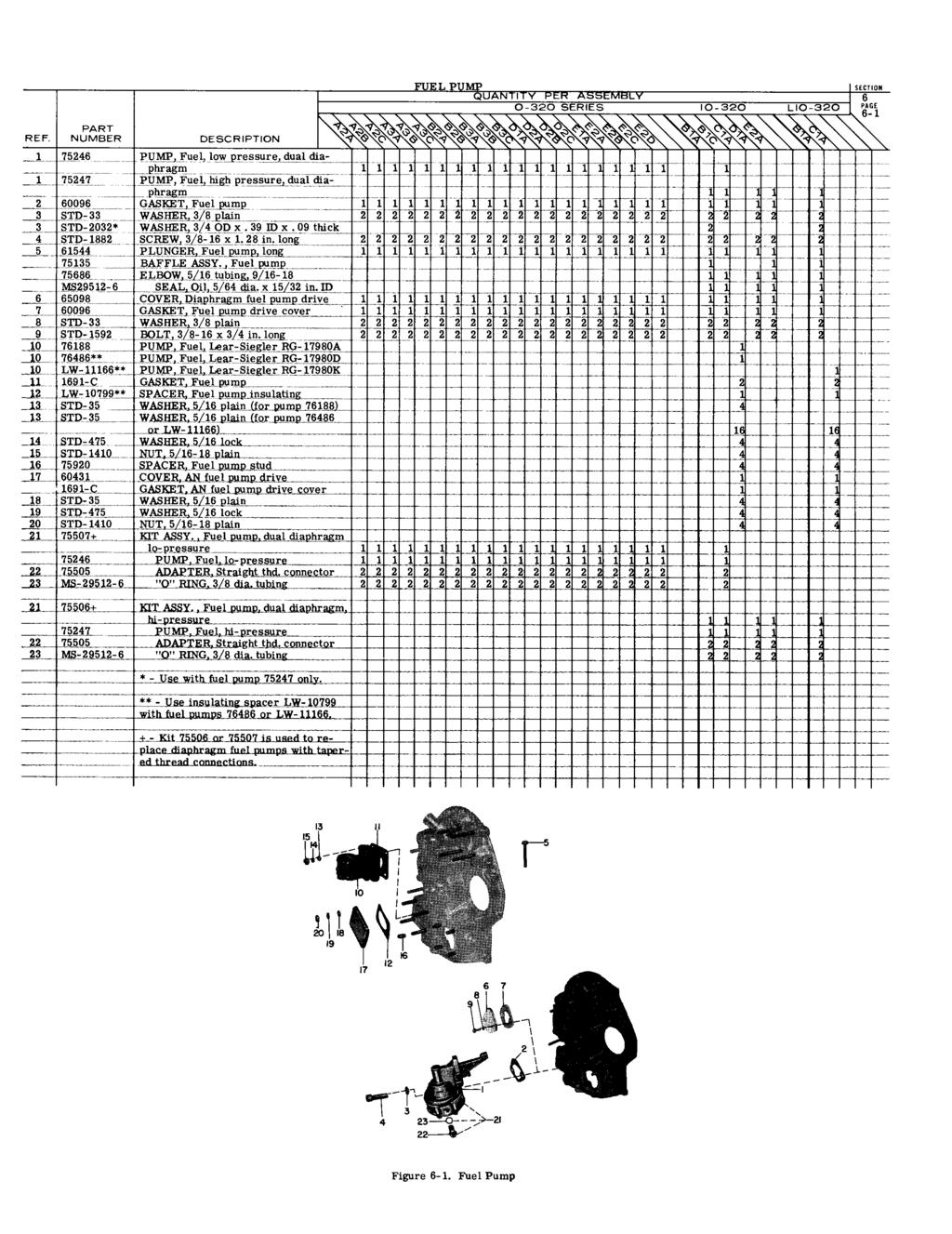
119
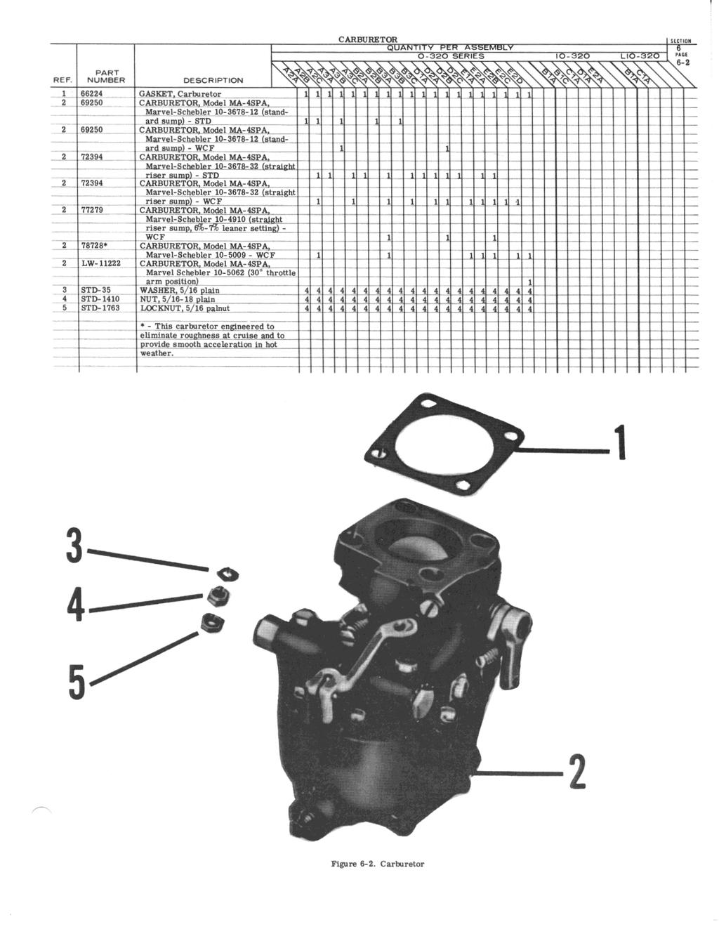
120
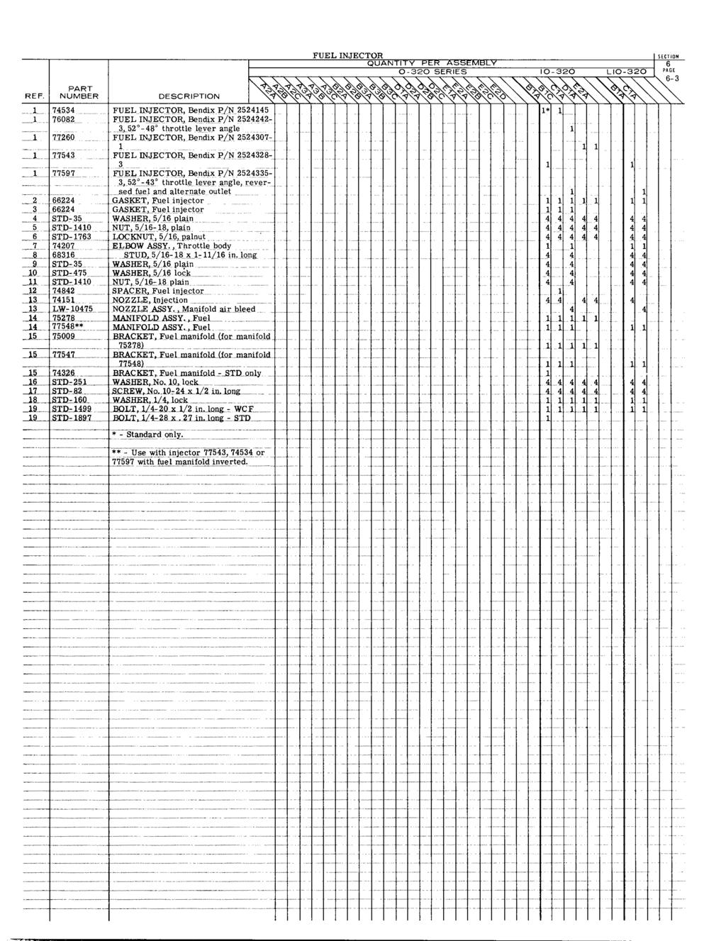
121
122 Figure 6-3. Fuel Injector
123
124
125 LYCOMING AIRCRAFT ENGINE GROUP ASSEMBLY PARTS LIST COOLING BAFFLES, EXHAUST, OIL GAGE AND PROP GOVERNOR OIL LINE
126 3
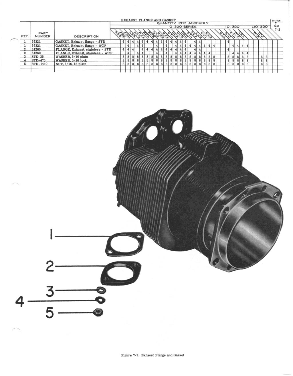
127 3 5

128 Figure l-3. Oil Level Gages
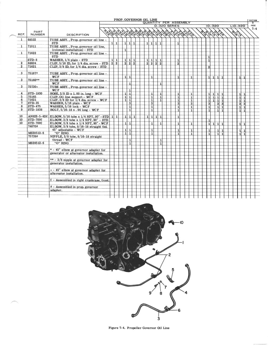
129 6
TEXTRON Lycoming AIRCRAFT ENGINES
 TEXTRON Lycoming AIRCRAFT ENGINES O-60-AP Wide Cylinder Flange Crankcase Model Engines PARTS CATALOG PC-06-6 MARCH 99 0-60-AP PARTS CATALOG This illustrated parts catalog contains a complete parts listing
Lycoming AIRCRAFT ENGINES. IO-540-AC1A5 Wide Series Flange Crankcase Model Engine PARTS CATALOG PC
 AIRCRAFT ENGINES IO-540-ACA5 Wide Series Flange Crankcase Model Engine PARTS CATALOG PC-5- November 008 Lycoming 5 Oliver Street Williamsport, PA 770 U.S.A. 570/33-8 IO-540-ACA5 PARTS CATALOG This illustrated
LYCOMING A Textron Company
 LYCOMING AEIO-360-HB PARTS CATALOG This illustrated parts catalog contains a complete parts listing for the Lycoming AEIO-360-HB wide cylinder flange crankcase model aircraft engines. Major assembly and
O-540-A4B5 PARTS CATALOG WIDE CYLINDER FLANGE CRANKCASE MODEL ENGINES
 INTRODUCTION This illustrated parts catalog contains a complete parts listing for the Lycoming O-540-A4B5 wide cylinder flange crankcase model aircraft engines. Major assembly and sub-assembly parts of
Lycoming Aircraft Engines Parts Catalog
 Aircraft Engines Parts Catalog IO-0-BG Wide Cylinder Flange Crankcase Model Engine Part No. PC-0- Oliver Street Williamsport, PA 770 Aircraft Engines Parts Catalog IO-0-BG Wide Cylinder Flange Crankcase
O-540-F1B5 SERIES PARTS CATALOG WIDE CYLINDER FLANGE CRANKCASE MODEL ENGINES
 INTRODUCTION This illustrated parts catalog contains a complete parts listing for the Lycoming O-540-F1B5 series wide cylinder flange crankcase model aircraft engines. Major assembly and sub-assembly parts
PUBLICATION REVISION
 Lycomlng 65 Oliver Street Williamsport, PA 770 U.S.A. 77/-6 TECHNICAL PUBLICATION REVISION REVISIOI No. PUBLICATION PUBLICATION No. PUBLICATION DATE IO-60-LA PC-06-A Engines PC-06- MAY, 996 This page(s)
TECHNICAL PUBLICATION SUPPLEMENT
 TEXTRON Lycoming TECHNICAL PUBLICATION SUPPLEMENT SUPPLEMENT No. ENGINE MODEL PUBLICATION No. PUBLICATION DATE PC-0--B O-90-D Series PC-0- January 9 This supplement is arranged in the same basic format
Lycoming Aircraft Engines Parts Catalog
 Lycoming Aircraft Engines Parts Catalog 76 Series O-360, LO-360 Series Part No. PC-3 65 Oliver Street Williamsport, PA 770 Lycoming Aircraft Engines Parts Catalog 76 Series O-360, LO-360 Series Part No.
TEXTRON Lycoming AIRCRAFT ENGINES
 TEXTRON Lycoming AIRCRAFT ENGINES O-60-CF & -CP Wide Cylinder Flange Crankcase Model Engines PARTS CATALOG PC-06- OCTOBER 995 65 Oliver Street Williamsport, PA 770 U.S.A. 77/-6 Lycoming O-60-CF &-CP PARTS
2003 Lycoming. All rights reserved. Lycoming and "Powered by Lycoming" are trademarks or registered trademarks of Lycoming.
 O-50-AD5 Engine Parts Catalog Lycoming Part Number: PC-55-3 003 Lycoming. All rights reserved. Lycoming and "Powered by Lycoming" are trademarks or registered trademarks of Lycoming. All brand and product
SUPPLEMENT TO NO. 105
 SUPPLEMENT TO Model 0-30 Series Aircraft Engines Parts Catalog NO. 05 This supplement is provided to inform users of Lycoming parts catalogs of changes, deletions, additions and supersedures that have
LYCOMING MODEL SERIES AIRCRAFT ENGINES TABLE OF CONTENTS INTRODUCTION iii. INSTRUCTIONS FOR ORDERING PARTS.. ILLUSTRATED PARTS SECTION..
 TEXTRON Lycoming AIRCRAFT ENGINES O-30 Model Aircraft Engine PARTS CATALOG LYCOMING MODEL 0-30 SERIES AIRCRAFT ENGINES TABLE OF CONTENTS INTRODUCTION....................... iii. INSTRUCTIONS FOR ORDERING
PARTS CATALDG AIRCRAFT ENGINES
 PARTS CATALDG PC B115-1 AVCC L VCCMING IC-154D-C4D15D MCDEL Wide Cylinder Flange Model AIRCRAFT ENGINES..JULY 19S2 L1L7AVCa LYCOMING WILLIAMSPORT DIVISION 852 Oliver Street. Williamsport. Pennsylvania
IO-540-K1H5 Series Illustrated Parts Catalog
 IO-50-KH5 Series Illustrated Parts Catalog November 983 Engine model IO-50-KK5, previously covered in this parts catalog, has been superseded by PC-5-KK5. PC-5-03 5 Oliver Street Williamsport, PA 770 IO-50-KH5
Lycoming Aircraft Engines Parts Catalog
 Lycoming Aircraft Engines Parts Catalog AEIO-50-D Series -DA5, -DB5 Wide Cylinder Flange Crankcase Model Engines Part No. PC-5-5 Oliver Street Williamsport, PA 770 Textron Lycoming 5 Oliver Street Williamsport,
Lycoming Aircraft Engines Parts Catalog
 Lycoming Aircraft Engines Parts Catalog TIO-360-CA6D Wide Cylinder Flange Models Part No. PC-06-3 65 Oliver Street Williamsport, PA 770 Lycoming Aircraft Engines Parts Catalog TIO-360-CA6D Wide Cylinder
Lycoming Aircraft Engines Parts Catalog
 Aircraft Engines Parts Catalog TIO-540 Series Standard Cylinder Flange Crankcase Models Part No. PC-35-6 652 Oliver Street Williamsport, PA 770 Reciprocating Engine Division/ Subsidiary of Textron Inc.
Lycoming Aircraft Engines Parts Catalog
 Lycoming Aircraft Engines Parts Catalog GO-480-B, -D and F6 Series Aircraft Engines Part No. PC-111 652 Oliver Street Williamsport, PA 17701 Lycoming Aircraft Engines Parts Catalog GO-480-B, -D and F6
O-320-A2B, -A3B Series Illustrated Parts Catalog
 O-320-A2B, -A3B Series Illustrated Parts Catalog August 2011 PC-203-1 2011 652 Oliver Street Williamsport, PA 17701 O-320-A2B, -A3B Illustrated Parts Catalog Lycoming Part Number: PC-203-1 2011 by Avco
O-320-A2C, -A2D Series Illustrated Parts Catalog
 O-320-A2C, -A2D Series Illustrated Parts Catalog September 2011 PC-203-2 2011 652 Oliver Street Williamsport, PA 17701 O-320-A2C, -A2D Illustrated Parts Catalog Lycoming Part Number: PC-203-2 2011 by Avco
O-360-C1G Series Illustrated Parts Catalog
 O-360-C1G Series Illustrated Parts Catalog April 2011 PC-306-4 2011 652 Oliver Street Williamsport, PA 17701 Lycoming Part Number: PC-306-4 2011 by Avco Corporation. All Rights Reserved. Lycoming and Powered
O-320-E2G Series Illustrated Parts Catalog
 O-320-E2G Series Illustrated Parts Catalog December 2011 PC-203-7 2011 652 Oliver Street Williamsport, PA 17701 O-320-E2G Illustrated Parts Catalog Lycoming Part Number: PC-203-7 2011 by Avco Corporation.
IO 360 M1B Series Illustrated Parts Catalog
 IO 360 M1B Series Illustrated Parts Catalog January 2011 PC 306 16 2011 652 Oliver Street Williamsport, PA 17701 Lycoming Part Number: PC 306 16 2011 by Avco Corporation. All Rights Reserved. Lycoming
O-320-E2D, -E3D Series Illustrated Parts Catalog
 O-320-E2D, -E3D Series Illustrated Parts Catalog October 2011 PC-203-6 2011 652 Oliver Street Williamsport, PA 17701 O-320-E2D, -E3D Series Illustrated Parts Catalog October 2011 PC-203-6 2011 652 Oliver
O-320-D3G Series Illustrated Parts Catalog
 O-320-D3G Series Illustrated Parts Catalog AUGUST 2012 PC-203-D3G 2012 652 Oliver Street Williamsport, PA 17701 O-320-D3G Series Illustrated Parts Catalog AUGUST 2012 PC-203-D3G 2012 652 Oliver Street
O-360-A4N Series Illustrated Parts Catalog
 O-360-A4N Series Illustrated Parts Catalog May 2011 PC-306-3 2011 652 Oliver Street Williamsport, PA 17701 Lycoming Part Number: PC-306-3 2011 by Avco Corporation. All Rights Reserved. Lycoming and Powered
Lycoming Aircraft Engines Parts Catalog
 Aircraft Engines Parts Catalog TIO/LTIO-540-V2AD Wide Cylinder Flange Model Part No. PC-35-2 652 Oliver Street Williamsport, PA 770 Aircraft Engines Parts Catalog TIO/LTIO-540-V2AD Wide Cylinder Flange
Lycoming Aircraft Engines Parts Catalog
 Aircraft Engines Parts Catalog TIO/LTIO-540-UA Series Wide Cylinder Flange Model Part No. PC-35-65 Oliver Street Williamsport, PA 770 Aircraft Engines Parts Catalog TIO/LTIO-540-UA Series Wide Cylinder
O 540 A4E5 Series Illustrated Parts Catalog
 O 540 A4E5 Series Illustrated Parts Catalog April 2012 PC 515 A4E5 2012 652 Oliver Street Williamsport, PA 17701 Lycoming Part Number: PC 515 A4E5 2012 by Avco Corporation. All Rights Reserved. Lycoming
IO-540-AE1A5 Series Illustrated Parts Catalog
 IO-540-AE1A5 Series Illustrated Parts Catalog PC-615-AE1A5 (Replaces PC-615-13) 2013 652 Oliver Street Williamsport, PA 17701 IO-540-AE1A5 Series Illustrated Parts Catalog PC-615-AE1A5 (Replaces PC-615-13)
O-320-E1A, -E2A Series Illustrated Parts Catalog
 O-320-E1A, -E2A Series Illustrated Parts Catalog November 2011 PC-203-3 2011 652 Oliver Street Williamsport, PA 17701 O-320-E1A, -E2A Illustrated Parts Catalog Lycoming Part Number: PC-203-3 2011 by Avco
TECHNICAL PUBLICATION REVISION
 Reciprocating Engine Division/ Subsidiary of Textron Inc. 65 Oliver Street Williamsport, PA 770 U.S.A. 77/33-68 TECHNICAL PUBLICATION REVISION REVISION No. PUBLICATION PUBLICATION No. PUBLICATION DATE
LYCOMING PARTS CATALO G
 LYCOMING PARTS CATALO G I O-70 AIRCRAFT SERIES ENGINES LYCOMING WILLIAMSPORT DIVISION WILLIAMSPORT, PENNSYLVANIA 770 PC-9 November 977 SUPPLEMENTAL PARTS LIST SSP77 To Provide Parts Coverage for Avco Lycoming
Lycoming Aircraft Engines Parts Catalog
 Lycoming Aircraft Engines Parts Catalog HO-360-CA Wide Cylinder Flange Crankcase Model Engines Part No. PC-306-0 65 Oliver Street Williamsport, PA 770 Lycoming Aircraft Engines Parts Catalog HO-360-CA
(L)IO-360-M1A Illustrated Parts Catalog
IO-360-M1A Illustrated Parts Catalog") (L)IO--M1A Illustrated Parts Catalog February 2016 PC-(L)IO--M1A (Supersedes PC-306-14) 2016 652 Oliver Street Williamsport, PA 17701 Lycoming Part Number: PC-(L)IO--M1A (Supersedes PC-306-14) 2016 by
(L)IO--M1A Illustrated Parts Catalog February 2016 PC-(L)IO--M1A (Supersedes PC-306-14) 2016 652 Oliver Street Williamsport, PA 17701 Lycoming Part Number: PC-(L)IO--M1A (Supersedes PC-306-14) 2016 by
O-360-A4M Series Illustrated Parts Catalog
 O-360-A4M Series Illustrated Parts Catalog PC-306-A4M 2012 652 Oliver Street Williamsport, PA 17701 O-360-A4M Series Illustrated Parts Catalog PC-306-A4M 2012 652 Oliver Street Williamsport, PA 17701 O-360-A4M
********NOTICE********
 IO-540-K1A5 Series Illustrated Parts Catalog February 2015 ********NOTICE******** This parts catalog, PC-615-K1A5 Series (models IO-540-K1A5, IO-540-K1A5D) supersedes the previous IO-540-K1A5, IO-540-K1A5D
Textron Company. A Textron Company. Engine Parts Catalog AEIO-360-BB -B1F & LYCYMNG Oliver Street Williamsport, PA Part No.
 Textron Company Engine Parts Catalog AEIO-60-BB -BF & -BH LYCYMNG 005 Decembber Part No. PC-06-005 65 Oliver Street Williamsport, PA 770 Textron Company Engine Parts Catalog AEIO-60-BB -BF & -BH LYCYMNG
LIO-360-B1G6 Illustrated Parts Catalog
 LIO-360-B1G6 Illustrated Parts Catalog July 2017 PC-LIO-360-B1G6 2017 Lycoming Part Number: PC-LIO-360-B1G6 For additional information: Mailing address: Lycoming Engines 652 Oliver Street Williamsport,
O-320-H 76 Series Illustrated Parts Catalog
 O-320-H 76 Series Illustrated Parts Catalog PC-122-H 76 Series 2013 652 Oliver Street Williamsport, PA 17701 O-320-H 76 Series Illustrated Parts Catalog PC-122-H 76 Series 2013 652 Oliver Street Williamsport,
TECHNICAL PUBLICATION REVISION
 Lycoming Textron Lycoming/Subsidiary of Textron Inc. 65 Oliver Street Williamsport, PA 770 U.S.A. 77/33-68 REVISION No. PC06--A TECHNICAL PUBLICATION REVISION ENGINE MODEL 0/LIO-360-C, -J, HIO, TIO, AEIO-360
YO-233-B2A Illustrated Parts Catalog
 YO-233-B2A Illustrated Parts Catalog March 2016 PC-YO-233-B2A Supersedes PC-901-1 2016 652 Oliver Street Williamsport, PA 17701 Lycoming Part Number: PC-YO-233-B2A Supersedes PC-901-1 2016 by Avco Corporation.
TIO-540-AJ1A Illustrated Parts Catalog
 TIO-540-AJ1A Illustrated Parts Catalog May 2016 PC-TIO-540-AJ1A (Supersedes PC-315-12) 2016 652 Oliver Street Williamsport, PA 17701 Lycoming Part Number: PC-TIO-540-AJ1A (Supersedes PC-315-12) For additional
TIO-540-AE2A Illustrated Parts Catalog
 TIO-540-AE2A Illustrated Parts Catalog December 2013 PC-315-7 Second Edition 2013 652 Oliver Street Williamsport, PA 17701 TIO-540-AE2A Illustrated Parts Catalog Lycoming Part Number: PC-315-7 2013 Lycoming.
TECHNICAL PUBLICATION SUPPLEMENT
 AVCO LYCOMING WILLIAMSPORT DIVISION 65 Oliver Street, Wlllamsport, Pennsylvania 770' AVCO LYCOMING ENGINE GROUP TECHNICAL PUBLICATION SUPPLEMENT SUPPLEEMENT No. ENGINE MODEL PUBLICATION No. PUBLICATION
Lycoming Aircraft Engines Parts Catalog
 Lycoming Aircraft Engines Parts Catalog TIO-541 Series Part No. PC-120 652 Oliver Street Williamsport, PA 17701 Lycoming Aircraft Engines Parts Catalog TIO-541 Series Part No. PC-120 652 Oliver Street
DEPARTMENT OF TRANSPORTATION FEDERAL AVIATION ADMINISTRATION TYPE CERTIFICATE DATA SHEET NO. 1E12
 DEPARTMENT OF TRANSPORTATION FEDERAL AVIATION ADMINISTRATION TYPE CERTIFICATE DATA SHEET NO. 1E12 1E12 Revision 9 Lycoming Engines IO-320 -A1A-A2A-B1A, -B1B, B1C, -B1E, -B1D, -B2A, -C1A, -C1B, -D1A, -D1C,
TIME OF COMPLIANCE: At owner s discretion or when part replacement is necessary.
 52 Oliver Street Williamsport, PA. 770 U.S.A. Telephone + (877) 839-7878 (U.S. and Canada) Telephone + (570) 327-7222 (International) Fax + (570) 327-70 Email Technicalsupport@lycoming.com www.lycoming.com
IO-390-C Series Engine Illustrated Parts Catalog
 IO-390- Series Engine Illustrated Parts atalog February 1, 2017 P-IO-390-2017 52 Oliver Street Williamsport, PA 17701 Lycoming Part Number: P-IO-390- For additional information: Mailing address: Lycoming
 REQUIRES SPECIAL TOOLS TO INSTALL. SEE REPAIR INSTRUCTION MANUAL. 411 718 38 3 1027 1 127 127 127A 1080 1081 1028 127 718A 127 718 44B 718A 2 44A 493 44 1069 112 718B 1019 LABEL KIT 1058 OWNER S MANUAL
REMOVAL AND INSTALLATION LABOR ALLOWANCE GUIDEBOOK FOR RECIPROCATING AIRCRAFT ENGINES
 REMOVAL AND INSTALLATION LABOR ALLOWANCE GUIDEBOOK FOR RECIPROCATING AIRCRAFT ENGINES SSP-875 Revision May 2000 2000 by Textron Lycoming All Rights Reserved -INTRODUCTION- The labor hours shown in this
Illustrated Parts List Vanguard to Compliance
 Non-Compliance Illustrated Parts List Vanguard Model Series 104700 to 104799 FORM MS-9878 7/93 REPLACES FORM MS-9878 5/92 FILE IN SECT. 2 OF SERVICE MANUAL 104700 to 104799 Compliance TYPE NUMBERS 0101,
Illustrated Parts List to
 Illustrated Parts List Model Series TYPE NUMBERS 0111 through 0199, 0200 through 0213, 0300 through 0353, 1345,1353, 2035 through 2073, 2135 through 2174, 4001 through 4090, 5001, 5005, 5006, 5035 through
GENSET ENGINE-G25/30. ITEM PART NO. DESCRIPTION QTY QTY REMARKS No. G25 G30
 ITEM PART NO. DESCRIPTION QTY QTY REMARKS No. G25 G30 1 CONTENTS SHEET DESCRIPTION PAGE NO. NO. E-1 CYLINDER BLOCK, LINER AND OIL SUMP 2 E-2 CYLINDER HEAD 6 E-3 PISTON AND CONNECTING ROD ASSY 10 E-4 CRANK
9/7/2014 T9.9ELRZ 2001 / TOP COWLING Yamaha Motor Corporation, U.S.A. All rights reserved.
 T9.9ELRZ 00 Page of 56 9/7/0 T9.9ELRZ 00 / TOP COWLING 0 Yamaha Motor Corporation, U.S.A. All rights reserved. T9.9ELRZ 00 Page of 56 9/7/0 Part List T9.9ELRZ 00 / TOP COWLING REF - NO PART NUMBER PART
Service Parts. John Deere 3029DF 3029TF 3029TF270. Engine. Engine Models: Generator Models: 20ROZJB REOZJB 20DSJB DSEJB.
 Service Parts Engine Engine Models: John Deere 3029DF 3029TF 3029TF270 Generator Models: 20ROZJB 20--40REOZJB 20DSJB 20--40DSEJB TP- 12/03b Table of Contents Description Page Description Page Introduction...
Lycoming Aircraft Engines Parts Catalog
 Lycoming ircraft Engines Parts Catalog GSO-80 and IGSO-80 Series ircraft Engines Part No. PC- Oliver Street Williamsport, P 770 Lycoming ircraft Engines Parts Catalog GSO-80 and IGSO-80 Series ircraft
9/7/2014 F9.9MSHV 1997 / CYLINDER CRANKCASE Yamaha Motor Corporation, U.S.A. All rights reserved.
 F9.9MSHV 997 Page of 45 9/7/04 F9.9MSHV 997 / CYLINDER CRANKCASE 04 Yamaha Motor Corporation, U.S.A. All rights reserved. F9.9MSHV 997 Page of 45 9/7/04 Part List F9.9MSHV 997 / CYLINDER CRANKCASE REF
Service Parts. Doosan 11.1 L. Engine. Engine Model: Generator Models: 180/200REZX 180/200RZX TP /09
 Service Parts Engine Engine Model: Doosan. L Generator Models: 80/00REZX 80/00RZX TP-0 /09 Table of Contents Introduction... Numbering System Significance... Illustrations... How to Find Part Numbers...
IO-390-A Series Engine Illustrated Parts Catalog
 IO-90- Series Engine Illustrated Parts Catalog July 20 PC-IO-90- (Supersedes PC-409-) 20 52 Oliver Street Williamsport, P 770 IO-90- Series Engine Illustrated Parts Catalog Lycoming Part Number: PC-IO-90-
SHEET DESCRIPTION PAGE NO. NO.
 CONTENTS SHEET DESCRIPTION PAGE NO. NO. E-1 CYLINDER BLOCK, LINER AND OIL SUMP 2 E-2 CYLINDER HEAD 6 E-3 PISTON AND CONNECTING ROD ASSY 10 E-4 CRANK SHAFT 12 E-5 TIMING GEAR COVER & SEALING 14 E-6 TIMING
9/9/2014 F15MSHC 2004 / TOP COWLING Yamaha Motor Corporation, U.S.A. All rights reserved.
 F5MSHC 00 Page of 6 9/9/0 F5MSHC 00 / TOP COWLING 0 Yamaha Motor Corporation, U.S.A. All rights reserved. F5MSHC 00 Page of 6 9/9/0 Part List F5MSHC 00 / TOP COWLING REF - NO PART NUMBER PART NAME QUANTITY
PARTS MANUAL SUPPORTED BY HUSTLER TURF EQUIPMENT AND EXCEL INDUSTRIES, INC.
 SHIBAURA DIESEL ENGINE MODEL: N843 and N843L PARTS MANUAL SUPPORTED BY HUSTLER TURF EQUIPMENT AND EXCEL INDUSTRIES, INC. Table of Contents Chapter 1 General Information....................................
TMTRON Lycoming AIRCRAFT ENGINES
 TMTRON Lycoming AIRCRAFT ENGINES 0-290-0 SERIES PARTS CATALOG PC1102-1 LyG rj:il~lf I(\IIIIII1 January 1988 L i~ii~l Lycoming Textron LycominglSubsidiary 652 Oliver Street of Textron Inc. Williamsport,PA
E70PL4EEC 1999 : CAMSHAFT [1/23] Page 1 of 49
![E70PL4EEC 1999 : CAMSHAFT [1/23] Page 1 of 49](/thumbs/96/129257940.jpg "E70PL4EEC 1999 : CAMSHAFT [1/23] Page 1 of 49") E70PL4EEC 1999 : CAMSHAFT [1/23] Page 1 of 49 E70PL4EEC 1999 : CAMSHAFT [1/23] 1 5030657 1 CAMSHAFT 2 5030658 1 PLATE, Camshaft thrust 3 5030549 1 SEAL, Camshaft 4 5030989 2 BOLT, Plate 5 5030663 8 ARM,
E70PL4EEC 1999 : CAMSHAFT [1/23] Page 1 of 49 E70PL4EEC 1999 : CAMSHAFT [1/23] 1 5030657 1 CAMSHAFT 2 5030658 1 PLATE, Camshaft thrust 3 5030549 1 SEAL, Camshaft 4 5030989 2 BOLT, Plate 5 5030663 8 ARM,
DEPARTMENT OF TRANSPORTATION FEDERAL AVIATION ADMINISTRATION
 DEPARTMENT OF TRANSPORTATION FEDERAL AVIATION ADMINISTRATION 1E10 Revision No. 22 TEXTRON Lycoming IO-360-A1A, -A1B, -A1B6, -A1B6D, -A1C, -A1D, -A1D6, -A1D6D, -A2A, -A2B, -A2C, -A3B6,-A3B6D, -A3D6D, -B1A,
DEPARTMENT OF TRANSPORTATION FEDERAL AVIATION ADMINISTRATION TYPE CERTIFICATE DATA SHEET NO. E-223
 DEPARTMENT OF TRANSPORTATION FEDERAL AVIATION ADMINISTRATION E-223 Revision 18 Textron Lycoming O-233-A1,O-235 O-235-A,-B,-AP,-BP-C,-C1,-C1A,-C1B,-C1C,-C2A,-C2B,-C2C, -E1,-E1B,-E2A,-E2B,-F1,-F1B,-F2A,-F2B,-G1,-G1B,-G2A,-G2B,
PARTS MANUAL. RGV12000/12100 Generator. Model. PUB-GP1420 Rev. 12/01
 PARTS MANUAL Model RGV12000/12100 Generator PUB-GP1420 Rev. 12/01 Copyright 2001 Robin America, Inc. GROUP INDEX Group Name Page GENERATOR... 4 PIPE FRAME... 6 CONTROL BOX... 8 2-WHEEL ASSY.... 12 4-WHEEL
Illustrated Parts List Industrial/Commercial to
 FORM MS-9479 6/95 REPLACES FORM MS-9479 10/94 FILE IN SECT. 2 OF SERVICE MANUAL 402700 to 402799 Illustrated Parts List Industrial/Commercial Model Series 402700 to 402799 TYPE NUMBERS 1115 through 1117,
DIAMO Discovery XLT PARTS CATALOG Engine First Edition August 2008
 DIAMO Discovery XLT PARTS CATALOG - 500 Engine First Edition August 2008 Copyright 2007-2008 LS MotorSports, LLC. Reproduction without written permission is completely forbidden. The information and diagrams
COMPRESSORS 09/97 CB-5C-050. Suggested Spare Parts for LB601 and LB601A Compressors: Qty./ Unit
 09/97 CB-5C-050 Suggested Spare Parts for LB601 and LB601A Compressors: Part # Description Qty./ Unit Comm. Qty. 794099 Gasket Set - Buna-N, Aluminum T 1 1 1 794259 Suction Valve Sub-Assembly T 2 2 794279
Illustrated Parts List to
 TYPE NUMBERS 0022 through 0035, 0040 through 0062, 0070, 0076,0100, 0102, 0120 through 0125, 0307, 0318,0320, 0326, 0340 through 0366, 0370 through 0378, 0382, 0385, 0390, 0391, 0394, 0398, 0402, Illustrated
Engine [P-TB216EBA] 3TNV74F-SPTB
![Engine [P-TB216EBA] 3TNV74F-SPTB](/thumbs/76/73516114.jpg "Engine [P-TB216EBA] 3TNV74F-SPTB") Ref. 0-1 Page 0-1 How to read this Parts Catalog Part No. ENGINE 3TNV74F-SPTB 2013.7.15 P-TB216EBA Ref. 0-1 Page 0-1 Ref. 0-2 Page 0-2 CYLINDER BLOCK 26 27 5 4 12 6 4 10 4 13 11 1 23 34 23 34 7 7 7 7 28
Ref. 0-1 Page 0-1 How to read this Parts Catalog Part No. ENGINE 3TNV74F-SPTB 2013.7.15 P-TB216EBA Ref. 0-1 Page 0-1 Ref. 0-2 Page 0-2 CYLINDER BLOCK 26 27 5 4 12 6 4 10 4 13 11 1 23 34 23 34 7 7 7 7 28
EXPLODED VIEW BASE AND PULLEYS Drawing No
 Generac NP-50LPG EXPLODED VIEW BASE AND PULLEYS Drawing No. 95865 20 Generac NP-50LPG REPAIR PARTS BASE AND PULLEYS Drawing No. 95865 ITEM DESCRIPTION PART NO. QTY. ITEM DESCRIPTION PART NO. QTY. 1 BASE,
FORD - Cyl Block and Related Parts
 FORD - Cyl Block and Related Parts Ref Description Qty All 302 Qty 351 Qty 351-HP 1 BLOCK ASSEMBLY 1 59-4046 1 59-4047 1 59-4047 2 PLUG - 1½ CUP - BRASS 6 59-4048 6 59-4048 6 59-4048 3 PLUG - OIL PASSAGE
9/8/ MSHZ 2001 / TOP COWLING Yamaha Motor Corporation, U.S.A. All rights reserved.
 9.9MSHZ 00 Page of 47 9/8/04 9.9MSHZ 00 / TOP COWLING 04 Yamaha Motor Corporation, U.S.A. All rights reserved. 9.9MSHZ 00 Page of 47 9/8/04 Part List 9.9MSHZ 00 / TOP COWLING REF - NO PART NUMBER PART
GREAVES COTTON LTD. SPARE PARTS CATALOGUE. G SERIES 3G11Tx - ENGINE GREAVES COTTON LTD.
 GREAVES COTTON LTD. SPARE PARTS CATALOGUE G SERIES 3G11Tx - ENGINE GREAVES COTTON LTD. Diesel Engines Unit, Chinchwad, Pune 411019, India, Tel: (91) 20 27473564 Fax: (91) 20-27472276 Document number. P
mi Model 108 Compact Tractor Parts Catalog
 mi Model 108 Compact Tractor Parts Catalog Catalog No. 1226 PRICE 75 CENTS CASE MODEL 108 COMPACT TRACTOR Parts Catalog No. 1226 Leitch 2500 9-72 "'^^^l" 1" ifif --C: ^1=5 t^dj d- CASE MODEL 108 COMPACT
Section 6 Exploded Views and Parts Lists. 42 Generac Power Systems, Inc.
 Control Panel Drawing No. 0D4946-A 42 Generac Power Systems, Inc. Control Panel Drawing No. 0D4946-A 1 091526 7 M5-0.8 X 12MM PHILLIPS PAN HD. MACH. SCR. 2 020093 1 BOX, CONTROL TOP 3 0D4226 1 BOX, CONTROL
Carrier Transicold Diesel Engine CT4-91-TV (V1505) Service Parts List Rev A
 Service Parts List Rev A") Carrier Transicold Diesel Engine CT--TV (V0) Service Parts List -0 Rev A Service Parts List DIESEL ENGINE CT--TV (V0) CONTENTS INTRODUCTION... REPLACEMENT ENGINE PART NO.... ORDERING INSTRUCTIONS... GENERAL
Carrier Transicold Diesel Engine CT--TV (V0) Service Parts List -0 Rev A Service Parts List DIESEL ENGINE CT--TV (V0) CONTENTS INTRODUCTION... REPLACEMENT ENGINE PART NO.... ORDERING INSTRUCTIONS... GENERAL
P773-2 For Model: M773LW2 PARTS MANUAL. Marine Generators Marine Diesel Engines Land-Based Generators
 P773-2 For Model: M773LW2 PARTS MANUAL Marine Generators Marine Diesel Engines Land-Based Generators CALIFORNIA Proposition 65 Warning: Diesel engine exhaust and some of its constituents are known to the
Mfg. No:
 Parts Manual Mfg. No: 220707-0142-99 Copyright 2017 Briggs and Stratton. All Rights reserved 22-Jun-2017 Model Components Table Of Contents Page Blower Hsg, Sump, Oil Fill.............................................................................
European Aviation Safety Agency
 European Aviation Safety Agency EASA TYPE-CERTIFICATE DATA SHEET Number: IM.E.032 Issue: 01 Date: 27 September 2012 Type: Lycoming Engines Models IO-360-A1A IO-360-C1B AEIO-360-A1E6 HIO-360-F1AD IO-360-A1B
Engine Parts Manual. Kubota Diesel Engine D1305-E3B-TXRN-1 WARNING Rev A
 9 8 9 0 8 - INCLUDES ITEMS - 0-Rev A Engine Parts Manual Kubota Diesel Engine D0-EB-TXRN- WARNING If incorrectly used, this machine can cause severe injury. Those who use and maintain this machine should
MGE Series Generators. Model MGE12000ROU. Parts Breakdown. NM Products Corporation 2002 All Rights Reserved
 MGE Series Generators Model MGE12000ROU Parts Breakdown NM Products Corporation 2002 All Rights Reserved Remarks on Parts Catalog 1. This parts catalog contains all parts for the MITSUBISHI GENERATOR MGE12000-ROU.
Illustrated Parts List to
 FORM MS-9491 6/94 REPLACES FORM MS-9491 8/93 FILE IN SECT. 2 OF SERVICE MANUAL 404700 to 404799 Illustrated Parts List Model Series 404700 to 404799 TYPE NUMBERS 1200 through 1207, 1211 through 1214, 1400,
Illustrated Parts List to
 FORM MS-2442-9/93 REPLACES FORM MS-2442-11/92 FILE IN SECT. 2 OF SERVICE MANUAL Illustrated Parts List Industrial/Commercial Model Series TYPE NUMBERS 0101 through 0104, 0116 through 0120, 0122 through
Section 7 Exploded Views and Parts Lists IMPACT-36 plus II Recreational Vehicle Generator Control Panel Drawing No. 0E7560
 Control Panel Drawing No. 0E760 10 7 4 8 6 6 49 44 47 8 9 1 1 11 9 40 41 41 8 9 14 1 1 19 6 19 9 1 1 1 4 7 6 14 46 16 17 4 7 8 0 7 0 10 4 4 4 48 0 1 40 Generac Power Systems, Inc. Control Panel Drawing
GXV530 DXA2 PARTS CATALOGUE
 GXV530 DXA2 PARTS CATALOGUE E-12 FAN COVER 001 16711-Z0A-000 STAY, FUEL PUMP 1 002 17211-Z0A-003 ELEMENT, AIR CLEANER 1 1022925 002 17211-Z0A-013 ELEMENT, AIR CLEANER 1 1022926 003 17218-Z0A-000 FILTER,
Illustrated Parts List to
 FORM MS-5838-9/94 REPLACES FORM MS-5838-10/93 FILE IN SECT. 2 OF SERVICE MANUAL 122700 to 122799 Illustrated Parts List Model Series 122700 to 122799 TYPE NUMBERS 0101 through 0108, 0115 through 0213,
Section 7 Exploded Views and Parts Lists. 40 Generac Power Systems, Inc.
 Control Panel Drawing No. 0E7560 50 10 7 4 8 6 6 49 5 44 47 8 9 1 1 11 9 5 40 41 41 8 9 14 15 1 19 6 19 9 1 1 1 5 4 7 6 14 46 16 17 4 7 8 0 7 0 10 4 45 4 48 51 40 Generac Power Systems, Inc. Control Panel
Illustrated Parts List to
 Illustrated Parts List Model Series 176400 to 176499 TYPE NUMBERS 0035, 0049, 0050, 0101, 0103, 0113, 0114, 0115, 0116. FORM MS 0419 9/97 REPLACES FORM MS 0419 5/97 FILE IN SECT. 2 OF SERVICE MANUAL 176400
Illustrated Parts List to
 Illustrated Parts List Vanguard Model Series 161400 to 161499 TYPE NUMBERS 0010 through 0036, 0040, 0041, 0047, 0049, 0051, 0070, 0073, 0079 through 0085, 0090, 0101, 0110 through 0135, 0199. FORM MS 9877
Diesel Engine. SERVICE PARTS LIST for V2203-DI ( ) Non--Electronic Speed Control Tier 2 Starting With S/N 3Y /13
 Non--Electronic Speed Control Tier 2 Starting With S/N 3Y /13") R Diesel Engine SERVICE PARTS LIST for V0-DI ( -009) Non--Electronic Speed Control Tier Starting With S/N Y00 --0 0/ SERVICE PARTS LIST DIESEL ENGINE V0 -DI ( -009) Non--Electronic Speed Control Tier Starting
R Diesel Engine SERVICE PARTS LIST for V0-DI ( -009) Non--Electronic Speed Control Tier Starting With S/N Y00 --0 0/ SERVICE PARTS LIST DIESEL ENGINE V0 -DI ( -009) Non--Electronic Speed Control Tier Starting
Parts Catalog. Generator Set TGHAA (Spec A C) Printed in U.S.A. Replaces (Spec A) 1 97
 Printed in U.S.A. Replaces (Spec A) 1 97") Parts Catalog TGHAA Generator Set Printed in U.S.A. 9 00 (Spec A C) 9 Replaces 9 00 (Spec A) 97 To avoid errors or delay in filling your parts order, always give the MODEL, SPEC NO. and SERIAL NO. from
Parts Catalog TGHAA Generator Set Printed in U.S.A. 9 00 (Spec A C) 9 Replaces 9 00 (Spec A) 97 To avoid errors or delay in filling your parts order, always give the MODEL, SPEC NO. and SERIAL NO. from
Illustrated Parts List to
 TYPE NUMBERS 0101, 0102, 0106, 0108, 0109, 0115 through 0224, 0415, 0418, 0467, 0468, 0601 through 0683, 3101 through 3108, 3110 through 3163, 3167 through 3181. Illustrated Parts List Model Series 124700
LB361B PARTS LIST COMPRESSORS CB-5E /06. Bulletins Needed For Complete Parts List. Gasket Set, Repair Kits and Special Tools
 COMPRESSORS CB-5E-031 2011/06 LB361B PARTS LIST Serial # ID# Gasket Set, Repair Kits and Special Tools Gasket Set Buna-N & Aluminum 793099 Top End Repair Kit 793229 Includes Piston Rings & Expanders, Packing
Illustrated Parts Catalogue
 Illustrated Parts Catalogue UL26Oi/iF/iS AERO ENGINE M00: IPC 260A0 Revision No : 0 Date: 207-0-9 Please fill in your engine and aircraft details for further reference: Engine Serial No. :... Aircraft
Lycoming Aircraft Engines Parts Catalog
 Lycoming ircraft Engines Parts Catalog IO/LIO-360-C, -J, HIO, TIO, EIO-360 Series Wide Cylinder Flange Models Part No. PC-06-65 Oliver Street Williamsport, P 770 Lycoming ircraft Engines Parts Catalog