MV12 SINGLE BUSBAR VACUUM SWITCHGEAR 12KV, 800/1250/2000/2500A, 25/31.5kA INSTALLATION, OPERATION AND MAINTENANCE INSTRUCTION MANUAL
|
|
|
- Lorin Barnett
- 6 years ago
- Views:
Transcription


1 INSTALLATION, OPERATION AND MAINTENANCE INSTRUCTION MANUAL MED MV REV 11 MV12 SINGLE BUSBAR VACUUM SWITCHGEAR 12KV, 800/1250/2000/2500A, 25/31.5kA 1
2 SAFETY...3 GENERAL CONSTRUCTION...3 OPERATING CONDITIONS...4 STORAGE CONDITIONS INSTALLATION FOUNDATIONS AND UNIT ERECTION FOUNDATION CHANNELS FOUNDATION BOLTS (EXPANDING TYPE) BUSBAR ASSEMBLY MAIN CABLES UNIT EARTHING MULTICORE CABLES & INTER-UNIT WIRING (BUS-WIRING) INTERLOCKS INSERTING/REMOVING THE CIRCUIT BREAKER INSERTING THE CIRCUIT BREAKER REMOVING THE CIRCUIT BREAKER MECHANICAL AND ELECTRICAL INTERLOCKS PADLOCKING CIRCUIT BREAKER CONTROL MODULE STRUCTURE AND FUNCTION STRUCTURE OF THE OPERATING MECHANISM FUNCTION OF THE ELECTRONIC CONTROL MODULE FUNCTIONS OF THE READY LAMP STORAGE CAPACITOR SENSOR SYSTEM OPERATION PREPARATORY WORK CIRCUIT-BREAKER OPERATION CLOSING OPENING OPENING ON FAILURE OF THE AUXILIARY POWER SUPPLY CLOSING ON FAILURE OF THE AUXILIARY SUPPLY CLOSING IN CIRCUIT EARTH POSITION OPENING IN CIRCUIT EARTH POSITION SERVICE AND GENERAL MAINTENANCE INSPECTION AND FUNCTIONAL TESTING SWITCHING DEVICES IN GENERAL OPERATING MECHANISM MAGNETIC ACTUATOR OPERATING MECHANISM STORAGE CAPACITORS SERVICING REPAIR SPARES COMMISSIONING CHECKS AND TEST PROGRAMME GENERAL CHECKS ELECTRICAL TEST SECONDARY INSULATION ELECTRICAL CIRCUITS CHECKS MEGGER TEST HIGH VOLTAGE TEST ELECTRICAL TESTS PRIMARY INSULATION MEGGER TEST HIGH VOLTAGE TEST HIGH VOLTAGE TESTS INTERGRITY OF VACUUM INTERRUPTER MECHANICAL TESTING AND RECORDING RECORDING COMMISIONING CHECK LIST COMMISIONING CHECK LIST CONTINUED
3 SAFETY Notes on safety at work Before working on the Switchgear it is necessary for the operator to ensure that it has been safely disconnected from electrical supplies and that the necessary safety earths have been fitted and a suitable permit to work issued. In the event of there being doubt in this respect the operator shall seek the advice of his local supply authority to ensure that he has taken the necessary actions to comply with local safety requirements. The circuit breaker actuator supply capacitor is capable of storing a considerable amount of charge and, therefore, care must be taken not to short the supply before discharge of the capacitor. To assist in its safe operation the equipment is fitted with padlocking facilities which shall be applied as appropriate. Before commencing work and after the completion of work any control switches shall be left in the appropriate positions. When any insulation testing is to be performed, make sure that the test voltage does not exceed 2kV r.m.s. All connectors are to be removed for the duration of the test. See fig Varistors, which are required for the EMC strength of the breaker controller, may otherwise be damaged. Should the operator require any guidance or advice regarding the equipment this can be obtained by contacting Medelec Switchgear Ltd. Our policy is one of continuous product development and the right is reserved to supply equipment, which may vary slightly from that described. GENERAL CONSTRUCTION Type MV12 metalclad indoor single busbar air insulated vacuum Switchgear is for use on distribution networks having the highest system voltage up to 12kV, a short circuit current rating up to 31.5kA, a maximum full load current of 2500A and a lightning impulse level up to 75 kvp (BIL). Standard incomer and feeder units comprise two main parts: the fixed housing with run out plate, and the horizontally isolated circuit breaker. The housing is fabricated from sheet steel with separated compartments for the circuit breaker, busbars and current transformers/cable box. Where isolatable and HV fused voltage transformers are fitted, they are housed in a separate compartment and are operated from the rear. An instrument panel at the front of the housing above the circuit breaker compartment accommodates the relay, instruments, terminal blocks, fuses and links for the secondary circuits. The multicore cable glands and terminations are situated at the back. The primary connection spouts in the circuit breaker compartment are equipped with earthed metal safety shutters, which are controlled by arms mounted on the sides of the circuit breaker compartment and operated automatically by movement of the circuit breaker. With the circuit breaker withdrawn from the housing, each shutter can be independently padlocked closed. For testing purposes, each shutter can be propped open with a self cancelling reset device. 3
4 OPERATING CONDITIONS Ambient temperature. Maximum +40 ºC Minimum - 40 ºC For increased ambient temperature current carrying capacity must be reduced. Provide additional ventilation for heat dissipation. STORAGE CONDITIONS All type MV12 switchgear is intended for clean indoor installation. Thus it is very important that all equipment is stored indoor at all times. Storing switchgear and breakers outside will subject the equipment to dirt and condensation. Humidity Highest mean value measured over 24 hours, Relative humidity 95% Highest mean value measured over 1 Month, Relative humidity 90% Avoid high humidity and/ or major rapid temperature fluctuations since these give rise to corrosion. To prevent condensation MV 12 switchgear is supplied with electric heater to preclude condensation. These must be switch on all the time even if the unit is switched off. Maximum site altitude: 1000m above sea level. 4
5 1.0 INSTALLATION 1.1 FOUNDATIONS AND UNIT ERECTION Correct operation of the Switchgear is dependent on it being level. It is essential, therefore, that care is taken at all stages of erection, in particular the lining up and leveling of the first unit, which will be the datum for all other units. Failure to erect the first unit correctly will result in misalignment throughout the switchboard. Foundation fixings may be of the foundation channel type See fig 1.1 or of the foundation bolt type, expanding type FOUNDATION CHANNELS Prepare the floor and foundations as shown on fig 1.1. Determine the highest point on the channels. This point then becomes the datum for all units. It is useful to use this point for erection of the first unit. With reference to the general arrangement drawing of the switchboard, check the unit serial numbers and remove the circuit breaker from the housing to be erected first. Position the housing on the channels. Locate the foundation bolts and associated washers through the holes in the base of the housing into the spring loaded nuts within the channels. DO NOT TIGHTEN. Using 2 plumb lines level the housing front to back and across the width. Levelling is carried out using the shim plates provided. These shims shall be located adjacent to and on the outside of the foundation bolts such that they will also support the adjacent housing when erected. Shims must also be placed under the base sheet at the front and the rear of the unit and under the circuit breaker runner plates to make up any gap between the floor. Position the next housing to be erected close up to the first, fit the foundation bolts and level up as before. Remove the housing top and rear covers and fit the inter-housing fixing screws. Repeat the above for the remaining housings remembering to check the unit serial numbers. Finally, tighten all foundation bolts and inter-housing fixings. Check the alignment of the instrument panels for squareness and equality of spacing between panels FOUNDATION BOLTS (EXPANDING TYPE) Proceed as section 1.1 and except use the foundation bolts instead. The holes in the base of the housing can be used as a template to drill the floor for accepting M12 x 75mm long expanding bolts. 1.2 BUSBAR ASSEMBLY Access to the busbar compartment for making the busbar joints is via removable covers on top of the housing, busbar chamber. Before assembly, all contact surfaces of the busbars and housing connections must be cleaned to ensure a good contact surface. Unplated contact surfaces shall be cleaned using fine grade emery cloth. Plated contact surfaces shall be cleaned using a branded liquid silver polish. After cleaning, all surfaces shall be wiped with a clean cloth to remove any metal dust, etc. Joints shall be assembled as soon as possible after preparation. The same treatment of contact surfaces shall be carried out on all other joints, such as the tee-off to voltage transformers and main cable connections. Units fitted with 5
6 voltage transformers are supplied with packers for transport only. These should be removed and replaced with the standard busbars (refer to fig 1.6). See fig 1.2 for assembly of busbars up to 1250A and refer to busbar layout drawings supplied with loose gear for 2000A and 2500A busbars. IMPORTANT: BUSBAR JOINTS ARE NOT TO BE INSULATED WITH PLASTIC COMPUND BUT LEFT BARE. cables are terminated on a multicore cable gland. See fig For ease of location, each wire is fitted with an identification ferrule, which corresponds with that on the wiring diagram. Where wires pass through to adjacent panels the holes shall be fitted with a protective grommet. 1.3 MAIN CABLES Access to the main cable terminations is via removable covers at the rear of the housing fig 1.3. The main cable shall be terminated to the cable connection busbar. Care must be taken to ensure that the fixing bolts supplied are used. Make sure that these bolts are not long more than necessary. 1.4 UNIT EARTHING The main earth bars of the units are combined within the unit. The only assembly required on site is, to connect the earth bars of adjacent unit together using the earth stud and earth spacer supplied with the loose gear. The earth bar must be terminated to the station earth system via the 12mm earth stud on the side frame. See fig MULTICORE CABLES & INTER-UNIT WIRING (BUS-WIRING) The only secondary wiring required on site is to run and terminate the multicore cables and connect the inter-unit bus-wires in accordance with the wiring diagrams supplied. The multicore cables are situated at the rear top side of the housing. The multicore 6
7 Figure 1. 1 Foundation Layout 7
8 Figure 1. 2 Busbar Assembly 8


9 Figure 1. 4 Main Earth Stud Figure 1. 3 Main Cable Box Figure 1. 5 Multicore Terminations 9

10 Figure 1. 6 Wood Packers between busbar monoblock and VT Connection for transport only. 10
11 2.0 INTERLOCKS 2.1 INSERTING/REMOVING THE CIRCUIT BREAKER INSERTING THE CIRCUIT BREAKER Bring the circuit breaker in front of the housing and attach the secondary plug on the switchboard to the secondary socket on the circuit breaker. Push the circuit breaker inside until no further movement is possible. Couple the racking handle into the Engage/Isolate seat. Start turning the handle clockwise to engage the circuit breaker to the plug contacts of the primary connection spouts. Stop turning the handle until Circuit Breaker Engaged on the base plate label can be read. Remove the racking handle and turn the isolating mechanism handle to the LOCKED Position REMOVING THE CIRCUIT BREAKER Turn the isolating mechanism to the FREE position. Insert the racking handle into the Engage/Isolate seat. Start turning the handle anti-clockwise to disengage the circuit breaker from the plug contacts of the primary connection spouts. Note that the circuit breaker stops moving at the end of the label until Circuit Breaker Disengaged is not visible. Remove the racking handle. Pull the circuit breaker from the handles outside the unit. N.B. It is essential that multi-fingered contacts are slightly greased with contact grease supplied with loose gear. 2.2 MECHANICAL AND ELECTRICAL INTERLOCKS Interlocks are provided to ensure that:- i. The circuit breaker can only be inserted into or withdrawn from a unit with the operating mechanism OFF and the isolating mechanism FREE. ii. iii. iv. The circuit breaker cannot be raised or lowered unless withdrawn from the unit with the operating mechanism OFF and the isolating mechanism FREE. The raise and lower drive shaft is blocked when the circuit breaker is racked in. Thus the raise and lower handle cannot be engaged. The circuit breaker can only be CLOSED with the isolating mechanism in the LOCKED position. The isolating mechanism can only be operated to the LOCKED position with the circuit breaker withdrawn or plugged in position and with the racking handle disconnected. v. The circuit breaker cannot be inserted into any other unit location other than that which has the same current rating. vi. The circuit breaker cannot be electrically TRIPPED when inserted in circuit earth position. vii. The circuit breaker can only be TRIPPED manually in the service position when no control voltage is 11
12 applied, and cannot be CLOSED manually. (Note: to close breaker when no D.C supply is available refer to section ) 2.3 PADLOCKING In addition to the interlocks described in section 2.2 padlocking facilities are provided for: i. For locking the unit safety shutters CLOSED. Fig. 2.1 & 2.2. ii. iii. iv. For locking the unit location selector in any one of the three locations, viz Busbar Earth fig 2.3, Circuit Service" fig 2.4 or Circuit Earth, fig 2.5 preventing selection of the other two. For locking the voltage transformer operating cover in both the SERVICE and OPEN position. fig 2.6 & 2.7 For locking the circuit breaker open switch in the OFF position see fig 2.8 or the OPEN/CLOSE switches (if fitted) inoperative see fig 2.9. v. For locking the circuit breaker control selector switch (if fitted) in either the LOCAL or REMOTE position. See fig CIRCUIT BREAKER CONTROL MODULE (refer to fig 2.10 & 2.12) The circuit breaker control module is used for control of the opening and closing commands to the magnetic actuator mechanism. Functions are defined in a permanently programmed logic module: i. The opening and closing of the circuit breaker can be controlled by applying a voltage to inputs (terminals 15,16) for ON operation and a voltage to inputs (terminals 17,18) for OFF operation. ii. iii. The moving contacts in the circuitbreaker poles must be in a defined ON or OFF limit position. The closing coil can only be activated with the breaker in the OFF position. iv. The opening coil can only be activated with the breaker in the ON position. v. Closing signal is blocked when an opening command is simultaneously active vi. Activation of the closing coil can be disabled by an external blocking signal. (terminals 25,26) vii. The antipumping system ensures that, when a closing command is applied and followed by an opening command, only one ON-OFF switching operation is performed. For the next closing operation, the active closing command has to be cleared and must be issued again. viii. Deactivation of the opening or closing coil takes place when the relevant limit position has been reached. ix. The closing coil can only be activated with the isolating mechanism in the locked position. These features are included with the auxiliary voltage (terminals 48,49) applied to the control module. 12


13 Figure 2.1 Locking of Busbar Safety Shutters Figure 2.2 Locking of Circuit Safety Shutters Figure 2.3 Locking in Busbar Earth Position Figure 2.4 Locking in Circuit Service Position Figure 2.5 Locking in Circuit Earth Position Figure 2.6 Voltage Transformer Padlocked in Service 13


14 Figure 2.7 Voltage Transformer Padlocked in Isolation Figure 2.8 Open Switch Padlocked in the Off Position Figure 2.9 Close Switch Padlocked Inoperative Figure 2.10 Local Remote Switch 14
15 Figure Control Module - Diagram of Connection 15

16 Figure 2.12 Control Module Inside the MV12 Breaker 16
17 3.0 STRUCTURE AND FUNCTION 3.1 STRUCTURE OF THE OPERATING MECHANISM The operating mechanism is of the magnetic actuator type. Referring to fig 3.1 it fundamentally consists of the magnetic actuator (7), the drive shaft (4), which transmits the force to the breaker poles (2) via the push rods (3). The actuator is the heart of the circuit breaker operating mechanism. It combines the following integrated functions: i. Latching in the limit positions ii. iii. Release to switch OFF Switching to switch ON The actuator is a bistable permanent magnet system in which the armature motion is effected by activating the ON or OFF coil The opening and closing processes are initiated via operation of push-button on the instrument panel. In the closing process, the actuator (7) acts on the three breaker poles via drive shaft (4) and the push rod (3) until the contacts meet. In the remaining movement, the pretension spring arrangement in the push rod is compressed to the required tension and the necessary contact force thus applied. The available over travel is greater than the maximum contact burn-off throughout the life of the vacuum interrupter. In the limit positions, the armature is held in place magnetically by the field of two permanent magnets. Release of a switching operation is effected by exciting one of the two coils until the latching force of the permanent magnets is exceeded. 3.2 FUNCTION OF THE ELECTRONIC CONTROL MODULE (refer to figs 2.11 & 3.2 and tables 1 & 2) 17 The Control module produces a voltage of 80V from any supply voltage within the input voltage range, with which the storage capacitor is charged. This is also used to generate a voltage of 12V to supply the breaker controller. The circuit breaker control module consists of: a microprocessor electronic optocouplers for input relays for output power electronics to control the actuator coils Along the functions described in section 2.4, this module has further functions: (refer to fig 3.2) Undervoltage release function. This input, (terminals 27,28) switches the MV12 breaker off if the voltage applied falls below the tolerance range stipulated in IEC The nominal value of the voltage supply to be monitored is selected by dip switch I In order to prevent switch-off when the voltage briefly falls below the specified level (e.g. on motor startup), a time delay can additionally be set. See dip switch I 1004 to set time delay. Dip switch I1002 has closing support for the undervoltage input (27,28). If this feature is activated a closing operation is allowed even if no voltage is applied to (terminals 27,28). After the performing of closing, the normal undervoltage function is active i.e. the controller will trip even if no voltage is applied after closing. AUTO-OFF at declining capacitor voltage. This function is usually deactivated. This means that the MV12 breaker can be opened and closed without any voltage being applied. However if it is activated when no voltage is applied the MV12 cannot be closed.
18 Monitoring of the closing and opening coil of the actuator. This function monitors the closing and opening coil of the actuator for cable breakage. If such a breakage is detected, the Ready lamp on the front panel of the switchboard goes out (fig3.5). The ready signal is connected via terminals 9,10. Maximum Unsuccessful Attempts After 10 incomplete shots the unit will go in the NOT READY condition. The MV12 breaker can no longer be operated. In this case it is necessary to reset the breaker controller by removing the auxiliary supply and wait for the capacitor to discharge (see section 5.1). This function saves the components on the breaker controller and forces the operator to check the circuit breaker. Contacts for position signalling Terminals 1,2 and 3,4 are a pair of NO contacts used to signal the ON and OFF positions respectively. 3.3 FUNCTIONS OF THE READY LAMP This lamp monitors the following conditions. supply of auxiliary power to the MV12 circuit breaker. detection of a defined on or off position by the position sensors. monitoring of the controlled function of the microprocessor. sufficient voltage at the capacitor of the next switching operation. continuity of the actuator coils. 3.4 STORAGE CAPACITOR (fig 3.4) operating sequence is available without recharging. The energy stored by the capacitor is permanently monitored. This is achieved by measuring the capacitor voltage. The Ready lamp indicates that auxiliary voltage is applied and the circuit breaker is ready for the impending switching operation. The criterion for the Ready lamp to light up is the energy in the storage capacitor at the particular time; otherwise an error signal is issued. Case 1: Breaker in the OFF position. The energy available in the capacitor is sufficient for an ON and an OFF switching operation. Case 2: Breaker in the ON position. The energy available in the capacitor is sufficient for an OFF-ON-OFF switching sequence. The energy available is sufficient for an OFF switching operation in the first 200 s after failure of the auxiliary power supply. (see also section 4.2.3). 3.5 SENSOR SYSTEM The systematic use of sensors permits control of the circuit breaker without using the auxiliary switches. Two inductive proximity switches (fig 3.3) are used to detect the mechanical limit positions, which also provide for selfmonitoring of the system. The energy for operation of the circuit breaker is stored electrically in a capacitor. This capacitor is designed in such a way that the energy for an OFF-ON-OFF 18
19 Table 1 Terminal Assignment (refer to fig 2.11) Terminal Use General Purpose Binary Outputs 1-2 OFF signal 1 (NOC) ON signal 1 (NOC) 9-10 READY (NOC) NOT READY (NCC) General Purpose Binary Inputs ON-Command OFF-Command Closing lock-out (closed circuit) Switching Command OFF (closed circuit) Magnetic Actuator Position 29 OFF Position 30 ON Position Vdc Vdc 33 0Vdc 34 0Vdc Power Output and Capacitor Link Vdc Vdc 37 0Vdc 38 0Vdc 39 + On Coil (+80Vdc) 40 + On Coil (+80Vdc) 41 + Off Coil (+80Vdc) 42 + Off Coil (+80Vdc) 43 - On Coil 44 - On Coil 45 - Off Coil 46 - Off Coil Auxiliary Supply and Auxiliary Capacitor Connection 47 Not used 48 Voltage Supply 49 Voltage Supply 50 -V Cap 51 +V Cap 10Kohm resistor 52 +V Cap 19
20 Table 2 Technical Characteristics of Control Module Input Voltage Power Consumption on the input side during a charging process Power consumption in normal position Charging times of the capacitor Initial charging on commissioning Recharging after a switching operation Binary Inputs Electrical Isolation from the electronics Electrical Isolation between the inputs Current consumption Inputs protected from voltage surges Binary Outputs Electrical Isolation from the electronics Electrical Isolation between the outputs Switching current ON Resistance Low Voltage Range 24 to 60Vdc 24 to 48Vac High Voltage Range 110 to 250Vdc 100 to 240Vac 100W <10W Max 10s Max 3s 2.0 kv AC kv AC 1 2mA at 250V AC/DC YES 2.0 kv AC kv AC 1 Max 6A / 250 V AC (resistive) 100mΩ 1) Note: When any insulation testing is to be performed, all the connectors on the card have to be disconnected for the duration of the test (see fig 3.6). 20

21 Figure 3.1 MV12 Circuit Breaker 21

22 Figure 3. 2 Jumper settings of the Control Module 22


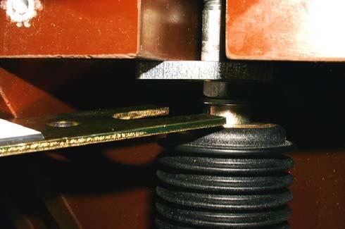
23 Figure 3.3 Proximity Sensors Figure 3.4 Storage Capacitors Figure 3.5 Circuit Breaker Ready Light Figure 3.6 Connectors Removed 23
24 4.0 OPERATION 4.1 PREPARATORY WORK Preparatory Work Before Connecting The Primary Voltage. i. Check the circuit-breaker for damage and have it repaired if necessary. ii. iii. iv. Remove any dirt which might have accumulated during transport, storage or installation (particularly on insulating materials). Check the primary and secondary connections and the earth conductor connection. In the case of a (voltage-free) storage period of more than 2 years, an increased current consumption, which is nevertheless below 2 A, occurs at the breaker control module during commissioning as a result of reforming the storage capacitor v. Display the instruction manual at a location accessible to the operators at all times. 4.2 CIRCUIT-BREAKER OPERATION Adjust the position selector switch to the position required. (fig 4.1) Make sure that the isolating mechanism handle is in the free position before raising or lowering breaker. (figs 4.2 & 4.3) For service position the breaker should be raised until the handle aligns with the arrow on the label. (fig 4.2) Check that the isolating mechanism can be operated FREE to LOCKED. For circuit earth position the breaker should be lowered until the handle aligns to the arrow on the label. (fig 4.3) Raise and Lower can only be done when the breaker is outside the housing. Once the breaker is racked inside the housing the racking handle cannot be inserted in the raise and lower seat. For the insertion and removal instructions of the breaker refer to section 2.1 With the circuit breaker outside the unit and the secondary socket lead plugged in, the supply is connected to the breaker. After 15 seconds that the auxiliary power supply has been established the Ready Lamp lights up and the breaker can be operated CLOSING Closing can only be achieved if all the interlocks are correct see section 2.2 & 2.4. The interlock handle must be moved from FREE to LOCKED. Closing can be done either by remote control via closing contacts on multicore terminal or locally by pressing the ON push-button on the instrument panel. (fig 4.4) OPENING Opening can be made by remote control via closing contacts on the multicore terminals or locally by pressing the OFF push-button on the instrument panel. After each operating cycle ON-OFF, the mechanical counter is incremented by one full digit. (figs 4.4 & 4.5) Perform test closing and opening of the circuit-breaker by pressing ON-OFF pushbuttons OPENING ON FAILURE OF THE AUXILIARY POWER SUPPLY Electrical opening is possible only within the first 200 s. of the auxiliary power 24
25 supply failure. After a period of 200 s, emergency manual opening is necessary:! Manual opening must be performed on a dead line only. To perform a manual opening when breaker is in service position, remove the front screws holding the cover of the circuit breaker and remove the circuit breaker front cover. Insert the Emergency Trip Handle into actuator shaft and turn it anticlockwise to open the circuit breaker. (figs 4.6 & 4.7) instructions on this device refer to the maintenance closing device instruction handbook. Having restored the supply to the battery and the auxiliary supply the other feeders can now be closed CLOSING IN CIRCUIT EARTH POSITION Closing can only be achieved electrically if all the interlocks are correct and the isolating mechanism handle moved, from FREE to LOCKED CLOSING ON FAILURE OF THE AUXILIARY SUPPLY! WHEN CLOSING A BREAKER WITH THE PROTECTION INACTIVE, IT IS COMMON PRACTICE TO SWITCH THE SUPPLY FROM THE REMOTE FEEDERS. Closing with auxiliary supply fail is not recommended with primary voltage energised OPENING IN CIRCUIT EARTH POSITION The electrical tripping of the circuit breaker in the Circuit Earth position is inoperative both during closing and when closed. This can only be achieved manually by using the Emergency Trip Handle (fig 4.8). In this case the cover does not need to be removed. In case of loss of the DC system, the circuit breaker can be closed, by using the Maintenance Closing Device. For 25


26 Figure 4.1 Position Selector Figure 4.2 Isolating Mechanism in the Free Position - Serviee Figure 4.3 Isolating Mechanism in Free Position Circuit Earth Figure 4.4 Close/Open Switches and Ready Lamp 26


27 Figure 4.5 Operations Counter Figure 4.6 Emergency Trip Handle used for Manuel Tripping Figure 4.7 Manual Trip in the Service Position Figure 4.8 Manual Trip in the Circuit Earth Position 27
28 5.0 SERVICE AND GENERAL MAINTENANCE The life expectancy of the MV12 vacuum circuit breaker is determined by: i. The maintenance-free vacuum interrupters with up to 20,000 operating cycles. ii. iii. The magnetic actuator mechanism, maintenance-free under normal operating conditions up to 100,000 operating cycles. The maintenance-free control module with sensor systems. The servicing intervals and scope are determined by the environmental influences, the switching frequency and the number of short-circuit breaking operations. In those applications where the load is switched many times a day, experience shows that the mechanical life is likely to be reached before the limit of contact wear. relevant safety regulations. It is recommended that Medelec Switchgear personnel should be called in, at least during the performance of servicing and repair work. Note: In order to prevent accidents (particularly injury to hands!) extreme care should be taken during all repair work on the operating mechanism, especially with circuit breaker front plate removed. The energy of the storage capacitor can be discharged uncontrollably during incorrect handling! Where the limit of contact wear has been reached on any phase, the complete set of 3 interrupters must be replaced. Replacements and the necessary instructions can be made available on application to Medelec Switchgear Ltd. Should the user identify any area of concern and require advice, the Contracts Department of Medelec Switchgear Ltd should be informed. On completion of an Overhaul, Commissioning Checks and Inspection should be carried out in accordance with Section 6 of this manual. Note: Maintenance work may only be performed by fully trained personnel, observing all the 28
29 5.1 PROCEDURE FOR CAPACITOR DISCHARGE i. Switch off the auxiliary power supply F2 (control & close fuse) ii. Switch the vacuum circuit-breaker on and off until it no longer responds. iii. After a waiting period of approx. 5 minutes, the storage capacitor will have discharged to <15V. 5.2 INSPECTION AND FUNCTIONAL TESTING SWITCHING DEVICES IN GENERAL Under normal operating conditions, inspection within the stated number of operating cycles is not necessary. Inspection may be necessary under exceptional operating conditions (including adverse climatic conditions) and/or particular environmental stresses (e.g. serious contamination and aggressive air). The inspection primarily comprises visual examination for contamination, corrosion, moisture and discharge phenomena on the high voltage side. If an irregular condition is found, appropriate maintenance work is to be initiated OPERATING MECHANISM A first functional test of the operating mechanism is to be performed during maintenance work. Before the functional test, switch off the circuit-breaker and withdraw the circuitbreakers. Observe the procedure for capacitor discharge as set down in section 5.1. Perform visual examination of the condition of the circuit breaker with the front plate removed, e.g.: i. the operating cycle counter, ii. the sensor mounting, iii. the position indicator. Functional testing: Connect the auxiliary power supply. Perform several switching operations under no load. This is predominantly applicable to circuit-breakers which are rarely operated under normal circumstances. To check the storage capacitor, switch the circuit-breaker rapidly OFF-ON-OFF once, by pressing ON and OFF push-buttons rapidly in succession. The LEDs on the inductive proximity switches fig 3.5 are activated when the circuit-breaker has reached its OFF and ON limit positions MAGNETIC ACTUATOR OPERATING MECHANISM The magnetic actuator operating mechanism is maintenance-free up to 100,000 operating cycles. Under normal operating conditions, inspection within the stated number of operating cycles is not necessary. Inspection may be necessary under exceptional operating conditions (including adverse climatic conditions) and/or particular environmental stresses (e.g. serious contamination and aggressive air). Inspection should be centred on the two Magnet Covers one on each side. If the brass magnetic cover is found crippled the circuit breaker should be kept out of service and the matter reported to Medelec Switchgear Ltd. 29
30 Circuit Breaker and Busbar chambers Before accessing any of these components make sure that the HV supply is de-energised and securely earthed STORAGE CAPACITORS Inspection may be necessary under exception operating conditions such as high temperature. Adverse climatic conditions and serious contamination of the air may also influence the lifetime of these capacitors. The vent of the capacitor must be examined to determine the state. If the vent is found ruptured, the capacitor must be immediately replaced. To perform this operation make sure that the capacitor discharge procedure (5.1) has been completed. 5.3 SERVICING If the necessity of cleaning is established during inspections the following procedure has to be done. Prior to cleaning, isolate and secure the working area safe. Observe procedure of capacitor discharge (5.1) Cleaning of insulating surfaces (cast-resin components) Circuit-Breaker Each vacuum interrupter housing has to be cleaned both from the outside and inside. To access all locations, polycarbonate covers and contact fingers have to be removed. Removing polycarbonate cover and contact fingers Unscrew the 4 nylon screw using a flat screwdriver. Use an allen-key size 5 to unscrew the upper and lower contact fingers. Clean thoroughly behind the polycarbonate covers using a lint free cloth. Busbar Monoblock This has to be accessed by removing the top cover. All insulating parts have to be cleaned using a lint free cloth. The other part has to be accessed from the circuitbreaker chamber. The shutter mechanism has to be opened to access all areas. CT Bushings Make sure that the cable connected to the bushings is de-energised and earthed. From the circuit-breaker chamber open the shutter in front of the bushings and put it in the open position. Clean all insulating surfaces using a lint free cloth. 5.4 REPAIR Replacement of circuit-breaker parts and accessories: Only remove and reassemble circuitbreaker parts and accessories when the breaker has been switched off and the working area is isolated and secured against reclosing: The storage capacitor is to be discharged in accordance with the instructions in section 5.1. All auxiliary voltage sources must be disconnected and secured to prevent reconnection during the removal and installation work. Replacement of the circuit-breaker control module may only be performed by Medelec Switchgear after-sales service staff or by trained skilled personnel. Remove all rust from damaged paintwork areas on sheet steel and other steel parts mechanically, e.g. with a wire brush. Lightly grind the surrounding paint coat 30
31 and carefully degrease the entire area. Then immediately apply an antirust primer and, after an appropriate hardening period, apply the top coat. Use top coat paint in the standard colour RAL 7032, or the relevant special colour. Only use suitable and compatible paint products. CRITERIA FOR OVERHAUL Interrupter Type Rating Current Rating Interrupter Mechanism ABB VG4 (VC on older version) 25kA or 31.5kA 800/1250/ A 1,000 operations 1,000 operations MINIMUM ELECTRICAL INTERRUPTER LIFE At Rated Normal Current At rated-short circuit current 5.5 SPARES 10,000 operations 30 operations The following spares should be kept in stock, actual quantities will depend on the number of circuit breakers in service and operating conditions. LT Fuses Voltage transformer High Voltage fuses. All spares should be stored in such a manner as to protect against corrosion, humidity, adverse atmospheric conditions, mechanical damage and vermin. When ordering spares or replacements a complete description should be given, together with relevant nameplate data and serial numbers. After the switchgear has been installed and all connections have been completed, commissioning tests are recommended to be performed. The purpose of these tests is to confirm that transportation and storage have not damaged the circuit breaker or any part of the fixed portion. In addition when the assembly adjustment is performed on site, tests are required to confirm compatibility of the sub-components and the satisfactory nature of both the site work and the functional characteristics. The purpose of the commission tests is for confirmation of: i. Absence of damage; ii. Compatibility of separate units; iii. Correct assembly; iv. Correct performance of the assembled unit 6.0 COMMISSIONING CHECKS AND TEST PROGRAMME The test outlined in this section is to be made after the equipment has been erected, but before energising. 31
32 6.1 GENERAL CHECKS Assembly to manufacturer's drawings and instructions; Tightness of circuit-breaker, and control devices; External insulation and internal insulation is undamaged and clean; Paint and other corrosion protection is sound; Operating devices, especially operating mechanisms, are free from contamination: Adequacy and integrity of the earth connection up to and including the interface with the substation earthing system. 6.2 ELECTRICAL TEST SECONDARY INSULATION ELECTRICAL CIRCUITS CHECKS Electrical Circuits conformity to the wiring diagram Correct operation of signalling lamps Correct operation of heating INSULATION TAKE THE FOLLOWING PRECAUTIONS: DISCONNECT THE WIRING TO THE BREAKER BY REMOVING THE SECONDARY PLUG DISCONNECT THE WIRING TO/WITHDRAW ANY RELAY DEVICES. SHORT CIRCUIT CURRENT TRANSFORMER SECONDARY WINDINGS. ISOLATE THE ISOLATABLE VOLTAGE TRANSFORMERS. AFTER COMPLETION OF TESTING, ALL CONDUCTORS SHALL BE DISCHARGED TO EARTH, TEMPORARY CONNECTIONS REMOVED AND COMPONENTS RECONNECTED. The secondary insulation includes the insulation associated with the secondary wiring. For this test the ends of the secondary wiring should be looped together at some convenient point such as the terminal board, and using a 500 volt megger measure the resistance, which should not be less than 2 megohms between the loops and earth HIGH VOLTAGE TEST MEGGER TEST WARNING: BEFORE COMMENCING THE TESTS DESCRIBED IN SECITONS AND ON THE SECONDARY 32 For this test the ends of the secondary wiring should be looped together at some convenient point such as the terminal board and a voltage of 2kV r.m.s. applied for 1 minute between the loops and earth. Remove connectors from the control module. Varistors which are required for the EMC strength of the breaker controller may otherwise be damaged. 6.3 ELECTRICAL TESTS PRIMARY INSULATION WARNING: BEFORE COMMENCING TESTS AND ON THE
33 PRIMARY INSULATION TAKE THE FOLLOWING PRECAUTIONS: SHORT CIRCUIT AND EARTH CURRENT TRANSFORMER SECONDARY WINDINGS. UNDER NO CIRUMSTANCES SHALL CURRENT TRANSFORMER SECONDARIES BE OPEN CIRCUITED WITH THE PRIMARY ON LOAD. ON FIXED VOLTAGE TRANSFORMERS REMOVE THE CONNECTION BETWEEN THE PRIMARY TERMINAL AND THE FIXED CONTACT ON ANY EARTHING SWITCHES. ISOLATE ANY ISOLATABLE VOLTAGE TRANSFORMERS. AFTER TESTING, ALL CONDUCTORS SHALL BE DISCHARGED TO EARTH, TEMPORARY CONNECTIONS REMOVED AND ANY COMPONENTS RECONNETED MEGGER TEST The primary insulation includes the insulation associated with the high voltage circuit. While carrying out this test it should be noted that, insulation varies considerably with atmospheric conditions, dryness and cleanliness of the equipment; low readings may occur as a result of surface leakage over the insulation. Using a 500V megger measure the resistance to earth of each phase in turn. If the resistance falls below an absolute minimum of 1000 megohms after careful cleaning and drying of all exposed surfaces, a check of the equipment should be made for insulation damage HIGH VOLTAGE TEST IEC60694: 2002 gives full information regarding high voltage testing after erection on site. With the circuit breaker CLOSED, a power frequency voltage should be applied to each phase in turn with the other two phases and the VCB frame earthed for 1 minute. 12kV highest system voltage 22.4kV AC rms power frequency. After high voltage tests have been completed, a further megger test should be made to check that the initial resistance has not altered significantly. 6.4 HIGH VOLTAGE TESTS INTERGRITY OF VACUUM INTERRUPTER The integrity of the vacuum interrupters can be checked on site by applying a test voltage of 20kV AC r m s or 30kV DC for 2 or 3 seconds across the open contacts of each phase in turn with the other side earthed. Provided that there is no evidence of breakdown the interrupter is in a satisfactory condition. Should a breakdown occur, the circuit breaker should be kept out of service and the matter reported without delay to Medelec Switchgear Ltd. 6.5 MECHANICAL TESTING AND RECORDING Manual operational checks should be carried out on the circuit breaker to ensure correct operation of interlocks, primary connection safety shutters, operating mechanism, trips, auxiliary switches and the circuit breaker racking mechanism. The equipment should be given a final inspection before it is put into service. Check that all covers are in place and fully secured. 33
34 Check earth bars for continuity. Check that all fuses and links are inserted. Check that padlocks are fitted. Check all moving parts of the safety shutters, the circuit breaker racking mechanism, circuit, isolatable voltage transformer operating mechanisms and all interlocks. Operate the circuit breaker electrically to ensure it is functional. Ensure all insulation surfaces are clean and dry. Touch up paint work where necessary RECORDING In order that a complete history is available, records should be started immediately after erection and should include: Date of Completion. Interrupter contact wear check. VC3 INTERRUPTERS See fig 6.1 for method of checking contact wear of VC3 interrupters. If contact wear gauge cannot be inserted in the snatch gap circuit breaker must not be used. VG4 INTERRUPTERS The polycarbonate brackets must be removed to check for contact wear. (see figs 6.2). If contact wear gauge CANNOT be inserted in the snatch gap (fig 6.2b) the MV12 breaker IS Operational. If contact wear gauge CAN be inserted in the snatch gap, the MV12 breaker IS NOT Operational and cannot be used. For this check MV12 breaker must be in the ON position. This gauge must be used as a Go No-Go check only. Number of short circuit operations. Details of any work carried out. Circuit breaker operations counter reading. Record the number on the operations counter at delivery; Record the number on the operations counter at completion of all site testing; Record the number on the operations counter at first energisation. Records are of value in establishing the frequency of maintenance, therefore careful notes should be taken of relevant items each time maintenance is carried out. These readings can be recorded in table attached. Under Section In order that a complete history is available, records should also be taken immediately after commissioning and should include: 34


35 Figure 6. 1 Contact Wear Gauge for circuit breakers with VC3 Interrupters 35


36 Figure 6. 2a Inserting the Contact Wear Gauge Figure 6. 2b No Contact Wear NO GO Figure 6.2c Contact Wear -GO Figure 6.2 Contact Wear Gauge for VG4 Interrupter COMMISIONING CHECK LIST A 1 Equipment bolted down correctly A 2 Instrument panels straight and aligned A 3 All gaskets and covers in place A 4 Prove tightness of all fastenings A 5 All insulators undamaged and clean A 6 Earth strap connections A 7 Labeling A 8 Switchgear Heaters A 9 Isolating and Earthing Arrangements A 10 Circuit-Breaker and Mechanism Alignment A 11 A 12 Auxiliary Switches Voltage transformer can be switched and isolated correctly B: ELECTRICAL CHECKS B 1 Battery charged B 2 DC available throughout switchboard B 3 All fuses checked B 4 Battery disconnection links left in open/close position after C: ELECTRICAL TESTS C 1 High voltage tests carried out is performed C 2 Primary and secondary injection tests carried out as per form 36
37 C 3 HV Switchboard volt meters checked at 110V and zeroed C 4 Power factor meters checked by secondary current injection and supply voltage C 5 KWH checked by secondary injection and supply voltage Remarks: TESTS CARRIED OUT BY: DATE:.. TESTS WITNESSED BY: EQUIPMENT ENERGISED: DATE: COMMISIONING CHECK LIST CONTINUED. DESCRIPTION VACUUM INTERRUPTERS 20 kv AC CHECK BREAKER ON/OFF COUNTER AT DELIVERY COUNTER AT COMPLETION COUNTR AT FULL ENERGISATION CONTACT WEAR CHECKED SHORT CIRCUIT OPERATION UNIT 1 UNIT 2 UNIT 3 UNIT 4 UNIT 5 UNIT 6 UNIT 7 Other Details 37
38 The right is reserved to alter design, dimensions and technical data without prior notice Manual MED MV REV 11 38
39 39
Vacuum Circuit-Breakers, Type HVX kv, of cassette design, cassette with motor drive
 Vacuum Circuit-Breakers, Type HVX 12 24 kv, of cassette design, cassette with motor drive Operating Instructions No. 531 321, Edition 09/00 Table of Contents 1 General 4 1.1 Operating Conditions 4 2 Design,
33KV INDOOR SWITCHGEAR
 33KV INDOOR SWITCHGEAR September 2017 Engineering Department WEST BENGAL STATE ELECTRICITY TRANSMISSION COMPANY LIMITED Regd. Office: VidyutBhawan, Block DJ, Sector-II, Bidhannagar, Kolkata 700091. CIN:
UBC Technical Guidelines Section Edition Commissioning of Electrical Systems Page 1 of 5
 Page 1 of 5 1.0 GENERAL 1.1 Coordination Requirements.1 UBC Building Operations Electrical Technical Support.2 UBC Energy & Water Services 2.0 REQUIREMENTS FOR COMMISSIONING AND TESTING 2.1 Testing.1 Unit
UniSec Maintenance solutions
 DISTRIBUTION SOLUTIONS UniSec Maintenance solutions ABB supports you to improve the reliability, safety and efficiency of your electrical equipment UniSec Maintenance solutions Table of contents 004 00
EISHO TEK. Vacuum Circuit Breaker
 EISHO TEK Vacuum Circuit Breaker TYPE:SV1-12 INSTRUCTION MANUAL Operation and Maintenance Version TAIWAN CALSONIC SAFETY PRECAUTIONS For safety reason, this equipment should be handled by personnel who
AMVAC TM technical guide Vacuum circuit breaker with magnetic actuator mechanism
 AMVAC TM technical guide Vacuum circuit breaker with magnetic actuator mechanism AMVAC Universal applications: Medium voltage motor starting applications Capacitor switching Retrofit applications to replace
1. Safety practices General Introduction Standards...3
 1. Safety practices...2 2. General...3 2.1 Introduction...3 2.2 Standards...3 3. Technical data...3 3.1 Designation...3 3.2 Electrical ratings and dimensions...4 3.3 Fixation...6 3.4 Connecting terminals...6
SION Vacuum Circuit-Breakers. Answers for energy. Medium-Voltage Equipment Selection and Ordering Data. Catalog HG
 Medium-Voltage Equipment Selection and Ordering Data Catalog HG 11.0 008 Answers for energy. R-HG11-17.tif Siemens HG 11.0 008 Contents Contents Page SION Vacuum Circuit-Breakers Description General Construction
SION Vacuum Circuit-Breakers. Answers for energy. Medium-Voltage Equipment Selection and Ordering Data. Catalog HG
 Medium-Voltage Equipment Selection and Ordering Data Catalog HG 11.02 2011 Answers for energy. R-HG11-172.tif 2 Siemens HG 11.02 2011 Contents SION Vacuum Circuit-Breakers Medium-Voltage Equipment Catalog
abb SafeLink SF 6 Insulated Ring Main Unit Installation and Operating Instructions Switchgear Division Auckland, New Zealand SLMIO ver 2.
 Installation and Operating Instructions Switchgear Division Auckland, New Zealand SLMIO ver 2.12 Product Overview ABB's type-tested ring main unit (RMU) is an SF 6 insulated RMU utilising the latest developments
GE Industrial Solutions. User/Installation Manual for 4.76kV -15kV SecoBloc
 GE Industrial Solutions User/Installation Manual for 4.76kV -15kV SecoBloc Index General Scope...3 Standards...3 Operating conditions...3 Technical specification...3 Basic structure Features...4 Operation...4
GE Consumer & Industrial Power Protection. New. SecoGear kV Metal-clad Switchgear. GE imagination at work
 GE Consumer & Industrial Power Protection New SecoGear 12-24kV GE imagination at work General SecoGear metal-clad switchgear is designed and manufactured with advance technology and has been comprehensively
Metal Clad Air Insulated Switchgear
 Metal Clad Air Insulated Switchgear 1/ SecoGear Metal Clad Switchgear Features Fully metal-clad Equipped with Embedded pole VCB Full Front access (can be installed against wall) Perfect interlocking system
BHARAT HEAVY ELECTRICALS LIMITED, JHANSI
 BHARAT HEAVY ELECTRICALS LIMITED, JHANSI DESIGN, MANUFACTURING, TESTING, SUPPLY INSTALLATION AND COMMISSIONING OF 11KV VACUUM CIRCUIT BREAKER NOTE : 1 VENDOR must submit complete information against clause
Power Break Circuit Breakers
 Draw Out 800-4000 Amperes GEH-46988 Installation Instructions Power Break Circuit Breakers POWER BREAK Draw Out Circuit Breaker (SOOA 4000A) DESCRIPTION Types TC, and THC Power Break draw out circuit breakers
OPERATING AND MAINTENANCE MANUAL. Primary Current Injection Test Set. 750ADM-H mk2
 OPERATING AND MAINTENANCE MANUAL Product: Type: Primary Current Injection Test Set 750ADM mk2 750ADM-H mk2 DESIGNED AND MANUFACTURED BY: T & R Test Equipment Limited 15-16 Woodbridge Meadows, Guildford,
Outdoor vacuum breaker for railway applications - FSK II
 Outdoor vacuum breaker for railway applications - FSK II Single or two-pole outdoor vacuum breaker with magnetic actuator 27.5 kv - 250 kv BIL - 1250 A. 2000 A - 25.0 ka - 50/60 Hz 27.5 kv - 200 kv BIL
ME Switchgear with Vacuum Circuit Breaker and Auto-jet II Switch with Ground Position
 LET S BE PACIFIC November 0 Volume Number 5 ME Switchgear with Vacuum Circuit Breaker and Auto-jet II Switch with Ground Position Federal Pacific has the capability to engineer, fabricate and assemble
VOLUME: IIIC SCHEDULE IIIC/4 11 KV AND 3.3 KV SWITCHGEARS
 VOLUME: IIIC SCHEDULE IIIC/4 11 KV AND 3.3 KV SWITCHGEARS A. 11 KV SWITCHGEAR 1.0 SWITCHGEAR ASSEMBLY 1.1 Make : 1.2 Type : 1.3 Reference Standard : 1.4 Voltage (Nom./Max.) KV : 1.5 Phase, Frequency No,Hz.
CR193 Vacuum Limitamp* Contactors
 GE Electrical Distribution GEH-5306C Maintenance Instructions CR193 Vacuum Limitamp* Contactors Contents Section 1 Introduction... 3 General... 3 Section 2 Description... 4 Principle of Operation... 4
Specification Guide. for RMVAC. Direct Replacement. AC Medium Voltage. Circuit Breakers
 Specification Guide for RMVAC Direct Replacement AC Medium Voltage Circuit Breakers Table of Contents 1.0 General Work Scope... 3 2.0 Standards... 3 3.0 Supplier Qualifications... 4 4.0 Circuit Breaker
SUBSTATION VACUUM CIRCUIT BREAKER (38KV)
") SUBSTATION VACUUM CIRCUIT BREAKER (38KV) For more than four decades, Myers Power Products has led the switchgear market in quality for the electric industry, delivering highly reliable products for utilities
SUBSTATION VACUUM CIRCUIT BREAKER (38KV) For more than four decades, Myers Power Products has led the switchgear market in quality for the electric industry, delivering highly reliable products for utilities
SUBSTATION VACUUM CIRCUIT BREAKER (25.8 / 27KV)
") SUBSTATION VACUUM CIRCUIT BREAKER (25.8 / 27KV) For more than four decades, Myers Power Products has led the switchgear market in quality for the electric industry, delivering highly reliable products
SUBSTATION VACUUM CIRCUIT BREAKER (25.8 / 27KV) For more than four decades, Myers Power Products has led the switchgear market in quality for the electric industry, delivering highly reliable products
SUBSTATION VACUUM CIRCUIT BREAKER (15.5KV)
") SUBSTATION VACUUM CIRCUIT BREAKER (15.5KV) For more than four decades, Myers Power Products has led the switchgear market in quality for the electric industry, delivering highly reliable products for utilities
SUBSTATION VACUUM CIRCUIT BREAKER (15.5KV) For more than four decades, Myers Power Products has led the switchgear market in quality for the electric industry, delivering highly reliable products for utilities
TECHNICAL SPECIFICATION OF 11KV SF6 / VCB METAL ENCLOSED, INDOOR (PANEL TYPE) / OUTDOOR RING MAIN UNIT (RMU). (IEC standard equipment)
 / OUTDOOR RING MAIN UNIT (RMU). (IEC standard equipment)") TECHNICAL SPECIFICATION OF 11KV SF6 / VCB METAL ENCLOSED, INDOOR (PANEL TYPE) / OUTDOOR RING MAIN UNIT (RMU). (IEC standard equipment) 1 SCOPE OF SUPPLY This specification covers design, manufacture, shop
TECHNICAL SPECIFICATION OF 11KV SF6 / VCB METAL ENCLOSED, INDOOR (PANEL TYPE) / OUTDOOR RING MAIN UNIT (RMU). (IEC standard equipment) 1 SCOPE OF SUPPLY This specification covers design, manufacture, shop
PATENT PENDING. Phone: (877) Operation and Service Manual
 Operation and Service Manual") PATENT PENDING Phone: (877) 544-2291 Operation and Service Manual 2 IMPORTANT NOTICE This document contains information intended to aid in the proper installation, operation, and maintenance of the product
PATENT PENDING Phone: (877) 544-2291 Operation and Service Manual 2 IMPORTANT NOTICE This document contains information intended to aid in the proper installation, operation, and maintenance of the product
MCset kv Medium voltage equipment
 Maintenance Guide PE90014 PE90006 MCset 1-2 - 3 17.5 kv Medium voltage equipment Air-insulated switchboards Metal-enclosed switchgear with moving parts PE90007 PE90008 PE90009 PE90007 Maintenance Guide
SafeGear Motor Control Center Arc Resistant Metal-Clad Construction Brochure
 2017 SafeGear Motor Control Center Arc Resistant Metal-Clad Construction Brochure SafeGear Motor Control Center Arc resistant Metal-Clad construction Brochure Table of Contents 1. Description 1 1 2. SafeGear
KYN28A-12 (GZS1) A.C METALCLAD REMOVABLE SWITCHGEAR FOR INDOOR USE CHINATCS
 A.C METALCLAD REMOVABLE SWITCHGEAR FOR INDOOR USE CHINATCS") KYN28A-12 (GZS1) A.C METALCLAD REMOVABLE SWITCHGEAR FOR INDOOR USE CHINATCS 2001.09 KYN28A-12 (GZS1) A.C Metalclad Removable Switchgear for Indoor Use --------The Leader in Switchgear Up to 12kV 1. The
KYN28A-12 (GZS1) A.C METALCLAD REMOVABLE SWITCHGEAR FOR INDOOR USE CHINATCS 2001.09 KYN28A-12 (GZS1) A.C Metalclad Removable Switchgear for Indoor Use --------The Leader in Switchgear Up to 12kV 1. The
SafeGear TM Motor Control Center Arc resistant metal-clad construction
 SafeGear TM Motor Control Center Arc resistant metal-clad construction Contents Description 2 SafeGear TM MCC applications 3 Electrical features 3 Standards 3 Standard service conditions 4 HCV vacuum contactor
ON LOAD GEARS OPERATIONAL AND MAINTENANCE MANUAL VACUUM CIRCUIT BREAKER TYPE VS12
 ON LOAD GEARS OPERATIONAL AND MAINTENANCE MANUAL VACUUM CIRCUIT BREAKER TYPE VS12 We thank you for having purchased VCB s from us. We are sure you will be very happy with the performance and service of
R-MAG Vacuum Circuit Breaker with Magnetic Actuator Mechanism 15.5 kv - 27 kv; 1200 A A
 R-MAG Vacuum Circuit Breaker with Magnetic Actuator Mechanism 15.5 kv - 27 kv; 1200 A - 3700 A R-MAG The R-MAG is truly the next generation in vacuum circuit breakers, combining industry recognized magnetic
ON LOAD GEARS OPERATIONAL AND MAINTENANCE MANUAL VACUUM CIRCUIT BREAKER TYPE VS36
 ON LOAD GEARS OPERATIONAL AND MAINTENANCE MANUAL VACUUM CIRCUIT BREAKER TYPE VS36 We thank you for having purchased VCB s from us. We are sure you will be very happy with the performance and service of
B kv T&D GAS INSULATED SWITCHGEAR
 GAS INSULATED SWITCHGEAR B 105 170 300 kv The increasing demand for electrical power in cities and industrial centers necessitates the installation of a compact and efficient distribution and transmission
Vacuum Switchgear Type VMX Spares Manual
 Vacuum Switchgear Type VMX Spares Manual Vacuum Switchgear Type VMX Spares Manual Foreward This manual has been primarily designed for easy identification of components / sub-assembly. Ordering Components
Type SIMOPRIME A4, up to 24 kv, Air-Insulated Medium-Voltage Switchgear
 Circuit-Breaker www.siemens.com/energy Switchgear Type SIMOPRIME A4, up to 24 kv, Air-Insulated Medium-Voltage Switchgear s Technology Circuit-Breaker Switchgear Type SIMOPRIME, up to 17.5 kv, Air-Insulated
Medium Voltage Standby non-paralleling Control GUIDE FORM SPECIFICATION
 Medium Voltage Standby non-paralleling Control 1. GENERAL GUIDE FORM SPECIFICATION A. The requirements of the contract, Division 1, and part 16 apply to work in this section. 1.01 SECTIONS INCLUDE A. Medium
Innovators in Protection Technology Moulded Case Circuit Breaker Instruction Manual
 Innovators in Protection Technology Moulded Case Circuit Breaker Instruction Manual 11-M61E TABLE OF CONTENTS HANDLING & MAINTENANCE Storage 1 Transport 1 STANDARD ENVIRONMENT 1 INSTALLATION AND CONNECTION
Medium voltage products UniSec DY800 New 24 kv air-insulated medium voltage switchgear to e-distribuzione specifications
 Medium voltage products UniSec Y800 New 24 kv air-insulated medium voltage switchgear to e-istribuzione specifications UniSec Y800 ubicles available Unit e-istribuzione specifications (Ed. 4) UniSec IS/1
BM kv Digital Insulation Tester USER MANUAL
 M BM5200 5 kv Digital Insulation Tester USER MANUAL CONTENTS Safety warnings...3 Symbols used on instrument...4 Cleaning...4 General description...5 Insulation resistance test modes...5 Automatic discharge...5
PIX-H Metal-clad switchgear up to 17.5kV
 AIR INSULATED SWITCHGEAR PIX-H Metal-clad switchgear up to 17.5kV for high rated applications Technical Specifications AREVA T&D Summary - Technical description... 3 - Standards... 6 - PIX in detail...
017: 1998 CEB STANDARD RING MAIN UNIT CEYLON ELECTRICITY BOARD SRI LANKA
 017: 1998 CEB STANDARD RING MAIN UNIT CEYLON ELECTRICITY BOARD SRI LANKA CONTENTS PAGE 1. Scope 2 2. System Parameters 2 3. Service Conditions 2 4. Applicable Standards 3 5. Basic Features 4 6. Quality
MEDIUM VOLTAGE PRODUCTS. Powerbloc Pre-assembled modules for building medium voltage switchgear
 MEDIUM VOLTAGE PRODUCTS Powerbloc Pre-assembled modules for building medium voltage switchgear Powerbloc are the ideal solution for replacing fixed circuit breakers with withdrawable circuit breakers,
Hollister-Whitney Elevator Corporation
 Hollister-Whitney Elevator Corporation Installation and Service Manual GL101, GL131, GL171, GL130A, GL185 and GL260 AC Permanent Magnet, Gearless Machines Page 1 of 32 Table of Contents I. Introduction
5kV to 38kV, 630 Amp to 4000 Amp Indoor or Outdoor Application
 The most advanced Arc-Resistant Switchgear, designed and built to provide maximum safety in the event of an Internal Arcing Fault. 5kV to 38kV, 630 Amp to 4000 Amp Indoor or Outdoor Application Page 1
Air-insulated switchgear UniGear type ZS1
 Air-insulated switchgear UniGear type ZS1 ABB Power Technologies / 1-7074 D 12-03-2003 - Air-insulated switchgear UniGear type ZS1 ABB Power Technologies / 2-7075 D 1 2-03-2003 - Rated voltage kv 12 17.5
Unified requirements for systems with voltages above 1 kv up to 15 kv
 (1991) (Rev.1 May 2001) (Rev.2 July 2003) (Rev.3 Feb 2015) (Corr.1 June 2018) Unified requirements for systems with voltages above 1 kv up to 15 kv 1. General 1.1 Field of application The following requirements
EMPAC Metal enclosed capacitor bank for wind applications
 EMPAC Metal enclosed capacitor bank for wind applications Introduction The EMPAC is a Metal Enclosed Capacitor Bank suitable for voltages between 1 kv and 36 kv for reactive compensation in MV networks
MV Air Insulated Switchgear TAP17. Technical Data TGOOD
 MV Air Insulated Switchgear TAP17 Technical Data TGOOD 2017.1 Operating environmental conditions Place of installation: Indoor or outdoor Ambient temperature: 25 ~ +40 (higher or lower temperature optional)
R-MAG. Vacuum Circuit Breaker with Magnetic Actuator Mechanism
 R-MAG Vacuum Circuit Breaker with Magnetic Actuator Mechanism R-MAG Features: Low maintenance 10,000 mechanical operations (five times ANSI requirements) Simple magnetic actuator Vacuum interruption Definite
SWITCHGEAR FOR SERVICE UP TO 36kV (CABLE AND OVERHEAD CONDUCTOR CONNECTED)
") PRODUCED BY THE OPERATIONS DIRECTORATE OF ENERGY NETWORKS ASSOCIATION Issue 3 2012 SWITCHGEAR FOR SERVICE UP TO 36kV (CABLE AND OVERHEAD CONDUCTOR CONNECTED) www.energynetworks.org 2012 Energy Networks
PRODUCED BY THE OPERATIONS DIRECTORATE OF ENERGY NETWORKS ASSOCIATION Issue 3 2012 SWITCHGEAR FOR SERVICE UP TO 36kV (CABLE AND OVERHEAD CONDUCTOR CONNECTED) www.energynetworks.org 2012 Energy Networks
Instruction manual. Type 3AH35-MA vacuum circuit breaker magnetic-actuator operator module.
 Instruction manual Type 3AH35-MA vacuum circuit breaker magnetic-actuator operator module Installation operation maintenance E50001-F710-K378-V6-4A00 www.usa.siemens.com/sdv7 Hazardous voltages and stored
Vacuum Circuit-Breaker Modules
 Vacuum s Medium-Voltage Equipment Catalog HG.5 998 Vacuum s Medium-Voltage Equipment Description Catalog HG.5 998 Siemens AG 998 NXACT Vacuum vacuum circuit-breaker module, kv Features DIN EN ISO 900
SYSclad switchboard equipped with draw out type vacuum circuit breaker closed dooroperationoperation. SYSclad 12 17,5kV A.
 SYSclad switchboard equipped with draw out type vacuum circuit breaker closed dooroperationoperation 630 3150A SYSclad 12 17,5kV 16 31,5kA Generalities SYSclad is a medium voltage switchboard metal clad
3AK OPERATING INSTRUCTIONS. Vacuum circuit-breaker module 3AK1 and 3AK3
 3AK Vacuum circuit-breaker module 3AK1 and 3AK3 OPERATING INSTRUCTIONS Order no.: 9229 9923 176 0B Ordering location: IC LMV LP PO P C41 AG 09.2013 en Siemens AG 2006. All rights reserved. For your safety
Dycon D1532SM. EN50131/PD6662 Grade 3, 12V 2A Power Supply. Technical Description Installation and Operating Manual DYCON POWER SOLUTIONS LTD
 Dycon D1532SM EN50131/PD6662 Grade 3, 12V 2A Power Supply Technical Description Installation and Operating Manual DYCON POWER SOLUTIONS LTD Tel: +44 (0)1443 471 900 Unit A Cwm Cynon Business Park Mountain
Vacuum Circuit Breaker Type VAD-3
 Instruction Bulletin Bulletin 6055-11 Vacuum Circuit Breaker Type VAD-3 4.76 kv, 29 ka (250 MVA) 4.76 kv, 41 ka (350 MVA) 8.25 kv, 33 ka (500 MVA) 15.0 kv, 18 ka (500 MVA) 15.0 kv, 28 ka (750 MVA) 15,0
MCset 4-24 kv Withdrawable SF6 circuit breaker
 Medium Voltage switchgear MCset 4-24 kv Withdrawable SF6 circuit breaker Instruction for use Contents General 2 Glossary 2 Symbols 2 Recommendations 3 General description 4 AD4 unit 4 AD4 unit with toroidal
CONTENT. EPE METALCLAD SWITCHGEARS AMS SERIES 12kV AMS METALCLAD SWITCHGEAR 24kV AMS METALCLAD SWITCHGEAR 40.5KV AMS METALCLAD SWITCHGEAR
 CONTENT EPE METLCLD SWITCHGERS SERIES EPE 1220 / - 12KV METLCLD SWITCHGER EPE 10D - 12KV METLCLD SWITCHGER EPE 24-24KV METLCLD SWITCHGER EPE 36-36KV METLCLD SWITCHGER EPE METLCLD SWITCHGERS MS SERIES 12
SecoVac * Ground & Test Device
 GE Industrial Solutions DEH-50007 Installation, Operation and Maintenance Manual SecoVac * Ground & Test Device For 5kV-15kV IEEE Metal-clad Switchgear Table of Contents 1. Introduction...6 Safety Precautions...6
& HIGH CURRENT DC POWER SUPPLIES INSTRUCTION MANUAL
 72-6850 & 72-6852 HIGH CURRENT DC POWER SUPPLIES INSTRUCTION MANUAL Table of Contents Introduction 2 Specification 2 Safety 4 EMC 5 Installation 6 Connections 6 Operation 7 Maintenance and Repair 8 www.tenma.com
VD4 Installation and service instructions kv A ka
 Medium voltage products VD4 Installation and service instructions 12... 36 kv - 630... 3150 A - 16... 50 ka Index For your safety! 1 I. Introduction 2 II. Programme for environmental protection 2 1. Packing
Horizontal Circuit Switchers
 > Transformer Protection > CIRCUIT SWITCHERS C A T A L O G B U L L E T I N General Application Southern States Types CSH and CSH-B Horizontal Circuit Switchers provide an economical, versatile, space saving
MODEL 520 REMOTE START ENGINE MANAGEMENT SYSTEM
 MODEL 520 REMOTE START ENGINE MANAGEMENT SYSTEM DSE 520 ISSUE 4 4/4/02 MR 1 TABLE OF CONTENTS Section Page INTRODUCTION... 4 CLARIFICATION OF NOTATION USED WITHIN THIS PUBLICATION.... 4 1. OPERATION...
AIR INSULATED EXTENDABLE SWITCHGEAR UP TO 12KV GUIDE
 AIR INSULATED EXTENDABLE SWITCHGEAR UP TO 12KV GUIDE Certificate Number FM35831 APPLICATION Typical Uses and Classification The MSGair switchgear is used in transformer and switching substations mainly
DISTRIBUTION SOLUTIONS. GSec Gas-insulated switching and isolating apparatus
 DISTRIBUTION SOLUTIONS GSec Gas-insulated switching and isolating apparatus GSec is a three-position SF6 gas-insulated switchdisconnector designed for use in medium voltage switchgear for secondary distribution
Dycon D2430 EN54-4 Fire Alarm Power Supply Series
 Dycon D2430 EN54-4 Fire Alarm Power Supply Series Technical Description Installation and Operating Manual Construction Product Regulation 0359-CPR-00434 Page 1 of 14 Contents 1. General... 3 1.1 Product
SF 6 Gas Insulated Switchgear Type SDH314 / SDHa314 for 72.5 to 145 kv
 Three Phase Encapsulated Type SF 6 Gas Insulated Switchgear Type SDH314 / SDHa314 for 72.5 to 145 kv 06B1-E-0002 Small Space Requirement, High Reliability and Safety ー 72.5 to 145 kv GIS, SDH314/SDHa314
UniSec Operation and maintenance manual
 Medium voltage products UniSec Operation and maintenance manual Safety 3 For your safety! 3 Skilled personnel 3 Critical messages 3 Contact us! 3 1. Introduction 4 1.1 General aspects 4 1.2 Operation and
SF6 GAS INSULATED METAL ENCLOSED SWITCHGEAR (GIS)
") SF6 GAS INSULATED METAL ENCLOSED SWITCHGEAR (GIS) About company The «Elektroapparat» plant starts its operation in 1922 as a plant manufacturing high-voltage electrical equipment. During the first two
SF6 GAS INSULATED METAL ENCLOSED SWITCHGEAR (GIS) About company The «Elektroapparat» plant starts its operation in 1922 as a plant manufacturing high-voltage electrical equipment. During the first two
NXPLUS C Single busbar. Maintenance-free for lifetime
 NXPLUS C Single busbar Maintenance-free for lifetime Energy Distribution Welcome! Page 2 Content Overview Technical data Typicals Panel design Circuit-Breaker panel Busbar Operation Metering Low-voltage
Central Inverter SUNNY CENTRAL 500HE-20/630HE-20/720HE-20/ 760HE-20/800HE-20
 Central Inverter SUNNY CENTRAL 500HE-20/630HE-20/720HE-20/ 760HE-20/800HE-20 Maintenance Manual SC500-800HE20-WH-en-10 98-4110410 Version 1.0 EN SMA Solar Technology AG Table of Contents Table of Contents
M-RING 24. SF6 Insulated Ring Main Unit Metal-Enclosed (LSC2A)
") M-RING 24 SF6 Insulated Ring Main Unit Metal-Enclosed (LSC2A) Contents General Description Advanced facilities and process Advanced design philosophy Definition of M-RING 24 Standards Service conditions
M-RING 24 SF6 Insulated Ring Main Unit Metal-Enclosed (LSC2A) Contents General Description Advanced facilities and process Advanced design philosophy Definition of M-RING 24 Standards Service conditions
Instruction for Installation and Operation
 KYN79 (i-ax) Metalclad Removable AC Metal-Enclosed Switchgear Instruction for Installation and Operation K 15 24 SM 01 02 Tianshui Changcheng Switchgear Factory January, 2007 Warning: This instruction
Submersible Vacuum Fault Interrupters
 Submersible Vacuum Fault Interrupters UG Distribution Medium Voltage Vacuum Fault Interrupters Functional Specification Guide PS024002EN Functional Specification for 2.4kV to 17.5kV UG Distribution Medium
User manual W-VACi. W-VACi 12 / 17.5 / 24 kv IEC Vacuum Circuit Breakers
 User manual W-VACi W-VACi 12 / 17.5 / 24 kv IEC Vacuum Circuit Breakers 65A7355H01 Rev.04 January 2013 www.eaton.com 2 Table of contents 1 Safety... 5 1.1 Safety precautions...5 1.2 Safety practices...5
Gas Insulated Metal-clad Switchgear, HMGS!
 Medium Voltage HMGS-G10 HYUNDAI Medium Voltage Gas Insulated Metal-clad Switchgear, HMGS! SF6 Gas Insulated Metal-clad Switchgear is an integrated assembly of vacuum circuit breaker, 3-position switch,
VD4. Installation and service instructions kv A ka
 VD4 Installation and service instructions 12... 24 kv - 630... 2500 A - 16... 31.5 ka For your safety! Make sure that the installation room (spaces, divisions and ambient) is suitable for the electrical
Circuit-Breaker Switchgear Type SIMOPRIME, up to 17.5 kv, Air-Insulated Medium-Voltage Switchgear.
 Circuit-Breaker Switchgear Type SIMOPRIME, up to 17.5 kv, Air-Insulated Medium-Voltage Switchgear www.siemens.com/energy Technology s Contents Application Page Benefits 2 Typical uses 2 and 3 Technical
All rights reserved. Neither this catalogue nor any part of it may be copied using any method or for any purposes. Most studies are legally protected.
 Issued: January 2013 Copyright by ZPUE Katowice S.A. All rights reserved. Neither this catalogue nor any part of it may be copied using any method or for any purposes. Most studies are legally protected.
Installation, Operation and Maintenance Manual. EVC Controller (from February 2007)
") Installation, Operation and Maintenance Manual (from February 2007) Publication 2698C (GB) 0207 1A 3319 8035B Donaldson reserve the right to alter design without notice. Freedom from patent restrictions
Installation, Operation and Maintenance Manual (from February 2007) Publication 2698C (GB) 0207 1A 3319 8035B Donaldson reserve the right to alter design without notice. Freedom from patent restrictions
Chapter 5 Part B: Ignition system - transistorised type
 5B 1 Chapter 5 Part B: Ignition system - transistorised type Contents Coil - testing........................................... 9 Distributor - overhaul..................................... 7 Distributor
MEDIUM VOLTAGE CE-B36 METAL CLAD SWITCHBOARDS. CE - B36 - C - en - REV
 CE - B36 - C - en - REV.00 2011.9 EDIU VOLTAGE EDIU VOLTAGE APPLICATION CE-B etal Clad switchboards are designed for use in public and industrial distribution system up to 36kV for the operation and protection
with Vacuum Circuit Breaker HAF
 M E T A L - C L A D S W I T C H G E A R Safety and Reliability with Vacuum Circuit Breaker HAF Flexible Design and Compact with Vacuum Circuit Breaker HVF Easy Installation and Maintenance We build a better
Horizontal Circuit Switchers
 > Transformer Protection > CIRCUIT SWITCHERS C A T A L O G B U L L E T I N General Application Southern States Types CSH and CSH-B Horizontal Circuit Switchers provide an economical, versatile, space saving
Metal Clad VCBs ~ Mk1
 Metal Clad VCBs ~ Mk1 DUVI 150/40 ROLL ON FLOOR VCBs Range: 6kV, 00A, 1.5kA, 12kV, 150A, 40kA ( 4A000A Bus-Bars ) ` Widest range for MV (up to 6kV) Distribution Networks Megawin make metal clad VCB Panels
GHA. Gas-Insulated Switchgear. Gas-Insulated Switchgear. Switchgear extension and replacement of a panel
 Gas-Insulated Switchgear GHA Gas-Insulated Switchgear Switchgear extension and replacement of a panel During this work, essential parts of the switchgear remain in operation No. AGS 535 066-01 Edition
Descriptive Bulletin. R-MAG TM magnetically actuated dead tank outdoor vacuum circuit breaker 15.5 kv - 38 kv
 Descriptive Bulletin R-MAG TM magnetically actuated dead tank outdoor vacuum circuit breaker 15.5 kv - 38 kv Introduction The R-MAG TM is truly the next generation in medium voltage vacuum circuit breaker
1-50 KVA SINGLE-PHASE SERVO REGULATOR INSTRUCTIONS FOR USE SERVO SINGLE-PHASE VOLTAGE REGULATOR
 1-50 KVA SINGLE-PHASE SERVO REGULATOR INSTRUCTIONS FOR USE SERVO SINGLE-PHASE VOLTAGE REGULATOR I Important Notice! Thank you for preferring us. Your product has been designed to protect your sensitive
RE-PR3-E-86&105 3-Phase Panel Mount 86 and 105kW
 Page 1 of 6 3-Phase Panel Mount 86 and 105kW Features: Benefits: 0-10Vdc, 0-5Vdc, 4-20mA or manual via potentiometer control input Over temperature protection with auto reset Enclosed panel mounting Efficient
Instruction manual. EK6 Earthing switch 36/40.5 kv
 Instruction manual EK6 Earthing switch 36/40.5 kv Your safety first always! That s why our instruction manual begins with these recommendations: Only install switchgear and/or switchboards in enclosed
Outdoor live tank vacuum circuit breaker Type OVB-VBF for 24/36/40.5 kv applications
 Outdoor live tank vacuum circuit breaker Type OVB-VBF for 24/36/40.5 kv applications ABB a global leader ABB is a global leader in power and automation technologies that enable utility and industry customers
University of Houston Master Construction Specifications Insert Project Name
 SECTION 26 13 13 MEDIUM VOLTAGE SWITCHGEAR PART 1 - GENERAL 1.1 RELATED DOCUMENTS: A. The Conditions of the Contract and applicable requirements of Divisions 0 and 1 and Section 26 00 01, Electrical General
Matrix APAX. 380V-415V 50Hz TECHNICAL REFERENCE MANUAL
 Matrix APAX 380V-415V 50Hz TECHNICAL REFERENCE MANUAL WARNING High Voltage! Only a qualified electrician can carry out the electrical installation of this filter. Quick Reference ❶ Performance Data Pages
SDV7. Outdoor distribution circuit breaker family 15.5 kv to 38.0 kv. usa.siemens.com/sdv7
 0 000 0000000 0000 000000 0000 000 0000000 0000 000000 0000 000 0000000 SDV7 Outdoor distribution circuit breaker family 5.5 kv to 8.0 kv usa.siemens.com/sdv7 SDV7 Brochure Brochure SDV7 The type SDV7
S&C Type FVR Substation Circuit Breaker
 S&C Type FVR Substation Circuit Breaker 15 kv to 38 kv, 200 kv BIL, 1200 A, Class 6065 Instructions for Installation 60553014 S&C ELECTRIC COMPANY Specialists in Electric Power Switching and Protection
Low-voltage switchgear MNS Light W. Installation, handling and operation. ABB LV Systems
 Low-voltage switchgear MNS Light W Installation, handling and operation ABB LV Systems MNS Light W switchgear is a flexible system that is primarily designed for motor control. The rated service voltage
ZX2.2 Gas-insulated medium voltage switchgear
 ZX2.2 Gas-insulated medium voltage switchgear 2 Brochure ZX2.2 Power engineering from ABB Solutions for the future As a technology group with global operations, ABB supplies the solutions of the future
UP TO 17,5 kv LSC 2B PM (METAL-CLAD) WITHDRAWABLE VACUUM CIRCUIT BREAKER MEDIUM VOLTAGE CUBICLES
 WITHDRAWABLE VACUUM CIRCUIT BREAKER MEDIUM VOLTAGE CUBICLES") UP TO 17,5 kv LSC 2B PM (METAL-CLAD) WITHDRAWABLE VACUUM CIRCUIT BREAKER MEDIUM VOLTAGE CUBICLES 1 TABLE OF CONTENTS 1. SCOPE 2. GENERAL 2.1 STANDARDS AND REGULATIONS 2.2 OPERATING CONDITIONS 2.3 DOCUMENTATION
UP TO 17,5 kv LSC 2B PM (METAL-CLAD) WITHDRAWABLE VACUUM CIRCUIT BREAKER MEDIUM VOLTAGE CUBICLES 1 TABLE OF CONTENTS 1. SCOPE 2. GENERAL 2.1 STANDARDS AND REGULATIONS 2.2 OPERATING CONDITIONS 2.3 DOCUMENTATION
1ZSC ABH en, Rev. 1. Motor-drive mechanisms, types BUE and BUL2 Maintenance guide
 1ZSC000498-ABH en, Rev. 1 Motor-drive mechanisms, types BUE and BUL2 Maintenance guide Original instruction The information provided in this document is intended to be general and does not cover all possible