THE ML-3471 TONER CARTRIDGE
|
|
|
- Annabella Sparks
- 6 years ago
- Views:
Transcription
1 SAMSUNG ML-3471 TONER CARTRIDGE REMANUFACTURING INSTRUCTIONS THE ML-3471 TONER CARTRIDGE DOC# 0438 By Mike Josiah and the technical staff at Summit Technologies a distributor of Summit and Uninet Products.

2 Remanufacturing the Samsung ML-3471 Toner Cartridge THE ML-3471 TONER CARTRIDGE F irst released in February 2008, the Samsung ML-3471ND printers are based on a 35ppm, 1200dpi engine. This particular model is network ready and has a duplexer built in. The ML-3471 has a first page out in under 9 seconds, uses a 400Mhz Processor and comes standard with 64Mb RAM,(Expandable up to 320Mb). The monthly duty cycle is 50,000 pages. These cartridges do not have a drum cover, and come new with a piece of heavy paper with foam glued to it taped around the cartridge. There are 2 cartridges available for these machines. The LY (ML-D3470A) is rated for 4,000 pages, and the HY (ML-D3470B) is rated for 10,000 pages. At the time of this writing three machines worldwide have been released using this engine. The ML-3471ND, ML-3470D, and the ML-3471DK The cartridges themselves are easy to remanufacture and with list prices (As of 3/1/08) of $ for the HY and for the LY, very profitable as well. Required Tools 1) Toner approved vacuum. 2) A small Common screw driver 3) A Phillips head screwdriver 4) Needle nose pliers Required Supplies Samsung ML-3471 Toner 250g for HY ML-D3470B and 125g for LY ML-D3470A cartridges (Preliminary amounts) Replacement Chip HY or LY New replacement Drum New Replacement Wiper Blade New replacement Doctor Blade New Replacement Developer Roller Conductive Grease Drum lubricating powder


3 1) Place the cartridge with the handle/supply chamber towards you. Remove the 3 screws on the right end cap. See Figure 1 Figure 4 Figure 1 4) On the opposite side of the cartridge, remove the three screws on the left end cap. See Figure 5 2) Gently pry off plastic drum axle bushing. Keep this bushing with the appropriate end cap when removed. Each side is different. See Figure 2 Figure 5 Figure 2 5) Gently pry off plastic drum axle bushing. Keep this bushing with the appropriate end cap when removed. See Figure 6 3) On the top and bottom back edge of the end cap, there are two plastic tabs. Press in on the tab and remove the right end cap. See Figures 3 & 4 Figure 3 Figure 6


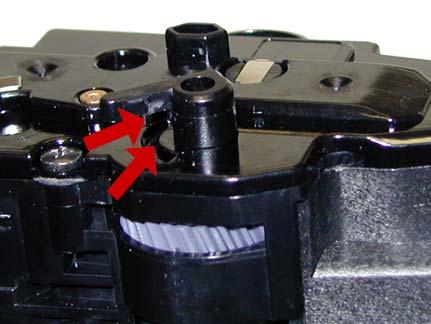
4 6) On the top and bottom back edge of the end cap, there are two plastic tabs. Press in on the tab and remove the left end cap. See Figures 7 & 8. 8) Carefully pry up the side plastic pieces on both sides to release the waste chamber. See Figures 10 & 11 Figure 7 Figure 10 Figure 11 Figure 8 9) Remove the waste chamber. See Figure 12 7) Lift off the roller assembly. See Figure 9 Figure 9 Figure 12


 Remove the developer roller.")

5 10) On the supply hopper, remove the fill plug and dump out any remaining toner. See Figure 13 Figure 16 Figure 13 11) Remove the developer roller drive gear; put a strip of tape across the remaining gears. They do not need to be removed the tape will help keep them in place See Figures 14 & 15 Figure 14 Figure 17 13) Remove the developer roller. See Figure 18 Figure 15 12) On the fill plug side, press in on the plastic tab and remove the spring/plastic bushing assembly. Be careful not to lose the spring! See Figure 16 & 17 Figure 18
 Replace the doctor blade and")
 Carefully pry up")
 Clean and install the")


6 14) Remove the two screws on the doctor blade. See Figure 19 19) Replace the doctor blade and 2 screws. See Fig. 22 Figure 22 Figure 19 16) Carefully pry up the doctor blade. See Figure 20 20) Clean and install the developer roller, long shaft side to gear side first. See Figure 23 Figure 20 17) Clean out any remaining toner from the hopper. Figure 23 21) Snap the spring/plastic bushing assembly in place. Make sure the tail of the spring is set properly. See Figures 24 & 25 18) Clean the doctor blade and foam seals. See Fig. 21 Figure 21 Figure 24
 On the waste hopper, remove the E-ring")
 Install the drive gear")
 Slide the drum")
 Fill")


7 Figure 25 Place the supply hopper aside 25) On the waste hopper, remove the E-ring from the drum axle. See Figure 28 23) Install the drive gear on the developer roller. See Figure 26 Figure 28 26) Slide the drum axle out from the side opposite the E- ring. See Figures 29 Figure 26 24) Fill the hopper with 250g of ML-3471 toner for the HY (10K cartridge and 125g for the LY 4K cartridge).replace the fill plug and check for leaks. See Figure 27 Figure 29 27) Remove the OPC drum. See Figure 30 Figure 27 Figure 30
 Clean the PCR with your preferred PCR cleaner.")


 Remove the two screws and the wiper blade.")

 Coat the new wiper blade with your preferred lubricant.")
8 28) Slide the PCR to the non contact side. Remove the PCR. See Figures 31 & 32 Figure 31 32) Clean the PCR with your preferred PCR cleaner. WARNING: Do not clean the OEM PCR with alcohol, as this will remove the conductive coating from the roller. If the PCR is an aftermarket, follow the cleaning methods recommended by the manufacturer. If the PCR is an OEM, we recommend it be cleaned with your standard PCR cleaner. 33) Clean the old conductive grease off the PCR shaft and contact. Replace with new. See Figure 35 Figure 32 29) Remove the two screws and the wiper blade. See Figure 33 Figure 35 34) Install the PCR by sliding the long shaft side through the non-contact side. Bring it back to fit into the contact side. See Figure 36 30) Clean out all the toner from the hopper. Figure 33 31) Coat the new wiper blade with your preferred lubricant. Install the new wiper blade and two screws. The tail of the wiper blade should face up. See Fig. 34 Figure 36 35) Coat the OPC drum with your preferred lubricant and install the drum. See Figure 37 Figure 34 Figure 37


 Install the E-ring.")


 Clean the foam")
9 36) Install the drum axle small drum gear side first. Make sure that the E-ring groove ends up on the small drum gear side. See Figures 38 & 39 Figure 38 Figure 41 Figure 39 37) Install the E-ring. See Figure 40 Figure 42 Figure 40 38) Install the waste hopper on to the supply chamber. Make sure that the tabs on both sides lock into place on the side wall. See Figures 41 & 42 39) Clean the foam rollers in the roller assembly with clean compressed air. 40) Install the roller assembly. See Figure 43 Figure 43


 Press the")


10 41) Install the right side end cap and three screws. Make sure the top rear tabs lock in place. Figs. 44 & 45 43) Remove the tape from the gears, and install the left side end cap and three screws. Make sure the top rear tab locks in place. See Figures 47 & 48 Figure 44 Figure 47 Figure 45 42) Press the drum axle bushing in place. Set it so the small tab is at the end of the groove; make sure it is fully seated. The two small bushings are different. Make sure you have the correct bushing for this side. See Fig. 46 Figure 48 42) Press the drum axle bushing in place. Set it so the small tab is at the end of the groove; make sure it is fully seated. The two small bushings are different. Make sure you have the correct bushing for this side. See Fig. 49 Figure 49 Figure 46

 47.")
11 43) The chip is held in place by plastic rivets. To replace the chip, drill out the plastic rivets and install 2 small self tapping screws. Install the two screws before you remove the cover so that the alignment does not change. You can now remove the screws and cover to replace the chip. See Figures 50 & 51 Configuration page Press the MENU button until Information appears on the display. Press Scroll Button until CONFIGURATION appears on the display Press the OK button. A configuration page will print out Repetitive Defect Chart Upper Fuser roller OPC Drum Lower Pressure roller Transfer Roller Supply roller PCR Developer Roller 77.8mm 75.5mm 62.8mm (Back of page) 47.1mm (Back of page) 44.9mm 37.7mm 35.2mm Machine Error Codes: Figure 50 The error codes put out by these machines are all in plain English and there is no need to go into them here. Expected printer part life: Transfer roller Fuser unit Pickup roller 70,000 pages 80,000 pages 150,000 pages Figure 51 Printing Test Pages: Demo Page Press the MENU button until Information appears on the display. Press Scroll Button until DEMO PAGE appears on the display Press the OK button. A demo page will print out
XEROX PHASER 3635 MFP
 XEROX PHASER 3635 MFP TONER CARTRIDGE REMANUFACTURING INSTRUCTIONS XEROX PHASER 3635 TONER CARTRIDGE REMANUFACTURING THE XEROX PHASER 3635 MFP TONER CARTRIDGE By Mike Josiah and the Technical Staff at
TONER CARTRIDGE REMANUFACTURING INSTRUCTIONS XEROX PHASER 3320 TONER CARTRIDGE
 XEROX PHASER 3320 TONER CARTRIDGE REMANUFACTURING INSTRUCTIONS XEROX PHASER 3320 TONER CARTRIDGE REMANUFACTURING THE XEROX PHASER 3320 TONER CARTRIDGE By Mike Josiah and the Technical Staff at UniNet First
ML-3712 MLT-D205 TONER CARTRIDGE REMANUFACTURING INSTRUCTIONS
 SAMSUNG ML-3712 MLT-D205 TONER CARTRIDGE REMANUFACTURING INSTRUCTIONS SAMSUNG MLT-D205 TONER CARTRIDGE CHANGES TO THE SAMSUNG MLT-D205 DRUM & CARTRIDGE By Mike Josiah and the Technical Staff at UniNet
TONER CARTRIDGE REMANUFACTURING INSTRUCTIONS OKIDATA B710/720/730 SERIES TONER CARTRIDGE
 OKIDATA B710/720/730 SERIES TONER CARTRIDGE REMANUFACTURING INSTRUCTIONS OKIDATA B710/720/730 SERIES TONER CARTRIDGE REMANUFACTURING THE OKIDATA B710/720/730 SERIES TONER CARTRIDGE By Mike Josiah and the
HP ENTERPRISE 600 M651/M680 SERIES TONER CARTRIDGE REMANUFACTURING INSTRUCTIONS
 HP ENTERPRISE 600 M651/M680 SERIES TONER CARTRIDGE REMANUFACTURING INSTRUCTIONS HP 652A TONER CARTRIDGE RREMANUFACTURING THE HP COLOR ENTERPRISE 600 M651/M680 SERIES TONER CARTRIDGES By Mike Josiah and
TONER CARTRIDGE REMANUFACTURING INSTRUCTIONS LASERJET P1505 SERIES TONER CARTRIDGE
 HP LASERJET P1505 TONER CARTRIDGE REMANUFACTURING INSTRUCTIONS HP LASERJET P1505 SERIES TONER CARTRIDGE 2010 UniNet Imaging Inc. All trademark names and artwork are property of their respective owners.
IMAGECLASS MF7200 SERIES (EP105) TONER CARTRIDGE REMANUFACTURING INSTRUCTIONS
 TONER CARTRIDGE REMANUFACTURING INSTRUCTIONS") CANON IMAGECLASS MF7200 SERIES (EP105) TONER CARTRIDGE REMANUFACTURING INSTRUCTIONS CANON EP105 TONER CARTRIDGE REMANUFACTURING THE CANON IMAGECLASS MF7200 SERIES EP105 TONER CARTRIDGE By Mike Josiah and
CANON IMAGECLASS MF7200 SERIES (EP105) TONER CARTRIDGE REMANUFACTURING INSTRUCTIONS CANON EP105 TONER CARTRIDGE REMANUFACTURING THE CANON IMAGECLASS MF7200 SERIES EP105 TONER CARTRIDGE By Mike Josiah and
LEXMARK C780 CARTRIDGE REMANUFACTURING INSTRUCTIONS LEXMARK C780 TONER CARTRIDGE
 LEXMARK C780 CARTRIDGE REMANUFACTURING INSTRUCTIONS LEXMARK C780 TONER CARTRIDGE REMANUFACTURING THE LEXMARK C780 BLACK & COLOR TONER CARTRIDGES First released in April 2008, the Lexmark C780 is based
Technical Document. Panafax UF-890 (actually revisiting the Panafax UF-550)
") Technical Document Disassembly Instructions SUMMIT Laser Products 95 Orville Drive Bohemia, New York 11716 Tel: 631-218-8376 Fax: 631-218-3275 Panafax UF-890 (actually revisiting the Panafax UF-550) Toner
Technical Document Disassembly Instructions SUMMIT Laser Products 95 Orville Drive Bohemia, New York 11716 Tel: 631-218-8376 Fax: 631-218-3275 Panafax UF-890 (actually revisiting the Panafax UF-550) Toner
1320 TO P2015 TONER CARTRIDGE CONVERSION INSTRUCTIONS
 HP 1320 TO P2015 TONER CARTRIDGE CONVERSION INSTRUCTIONS HP 1320 TO P2015 CONVERSION KIT (UNINET PART #1114) HP 1320 TO P2015 TONER CARTRIDGE CONVERSION INSTRUCTIONS By Javier Gonzalez and the Technical
XEROX WORKCENTRE 4150
 XEROX WORKCENTRE 4150 TONER CARTRIDGE REMANUFACTURING INSTRUCTIONS 013R00623 DRUM UNIT REMANUFACTURING THE XEROX WORKCENTRE 4150 DRUM UNIT By Enrique E. Estura, Daniel Reyes, and the Technical Staff at
HP LASERJET
 HP LASERJET 4200 4300 TONER CARTRIDGE REMANUFACTURING INSTRUCTIONS HP LASERJET 4200 TONER CARTRIDGE (Q1338A) HP LASERJET 4300 TONER CARTRIDGE (Q1339A) REMANUFACTURING HP LASERJET 4200/4300 TONER CARTRIDGES
MINOLTA MAGICOLOR 5430/5440/5450 CARTRIDGE REMANUFACTURING INSTRUCTIONS
 MINOLTA MAGICOLOR 5430/5440/5450 CARTRIDGE REMANUFACTURING INSTRUCTIONS MINOLTA MAGICOLOR 5430 Color Laser Printer with Toner Cartridge MINOLTA MAGICOLOR 5430 TONER CARTRIDGE SIDE VIEW WITH END CAP SHOWN
KONICA MINOLTA MAGICOLOR
 KONICA MINOLTA MAGICOLOR 5430 5440 5450 TONER CARTRIDGE REMANUFACTURING INSTRUCTIONS KONICA MINOLTA MAGICOLOR 5430 TONER CARTRIDGE REMANUFACTURING THE KONICA MINOLTA MAGICOLOR 5430/5440/5450 TONER CARTRIDGES
HP 5500 COLOR LASER PRINTER W/TONER CARTRIDGES
 AbsoluteCOLOR AbsoluteBLACK UniDrums UniRollers UniParts UniCoatings AbsoluteCOLOR AbsoluteBLACK UniDrums UniRollers UniParts UniCoatings HP 5500 CARTRIDGE REMANUFACTURING INSTRUCTIONS HP 5500 COLOR LASER
Sharp AR-160 OPC Cartridges DOC-0270
 Home New Arrivals! Company Info Publications Special Features Contact Us Overview Tools Required Supplies Needed Disassembly Recommended Supplies Sharp AR-160 OPC Cartridges DOC-0270 OVERVIEW The Sharp
TPE CC1997CRS HP M252/MFP M277 X TONER HOPPER 60GRMS FILL(WITH SEAL) OEM HP M252/MFP M277 (CF400A-CF403A
 OEM HP M252/MFP M277 (CF400A-CF403A") Installation Instructions for TPE CC1997CRS HP M252/MFP M277 X TONER HOPPER 60GRMS FILL(WITH SEAL) OEM HP M252/MFP M277 (CF400A-CF403A or CF400X-CF403X) Cartridge T.P.E. CC1997CRS HP M252/MFP M277 X TONER
Installation Instructions for TPE CC1997CRS HP M252/MFP M277 X TONER HOPPER 60GRMS FILL(WITH SEAL) OEM HP M252/MFP M277 (CF400A-CF403A or CF400X-CF403X) Cartridge T.P.E. CC1997CRS HP M252/MFP M277 X TONER
DRUM UNIT REMANUFACTURING INSTRUCTIONS
 Absolute COLOR Absolute BLACK Unidrums Unirollers Uniparts Unicoatings EPSON ACULASER C2600 DRUM UNIT REMANUFACTURING INSTRUCTIONS EPSON ACULASER C2600 COLOUR LASER PRINTER EPSON ACULASER C2600 DRUM UNIT
Conversion Kit for HP1200 Cartridge
 OEM HP1200 (C7115A) Cartridge Conversion Using T.P.E. CC1197 Canon EP26/EP27/X25/U Type Conversion Kit for HP1200 Cartridge OEM HP1200 (C7115A) T.P.E. CC1197 Canon EP26/EP27/X25/U Type Conversion Kit for
DELL C 5100 TONER CARTRIDGE REMANUFACTURING INSTRUCTIONS
 DELL C 5100 REMANUFACTURING INSTRUCTIONS DELL C 5100 LASER PRINTER DELL C 5100 REMOVING THE GEARLESS END CAP 1. Remove the gearless end cap (shown) to access the toner fill cap. Using a small flathead
5 Removal and replacement
 5 Removal and replacement This chapter describes the removal and replacement of field-replaceable units (FRUs) only. Removal and replacement strategy User-replaceable parts Covers Internal assemblies ENWW
Main Cover and Paper Input Assembly removal
 Main Cover and Paper Input Assembly Remove the toner cartridge. Remove memory door (HP LaserJet 5L and 6L). CAUTION Remove the memory door first (HP LaserJet 5L and 6L). The door will break if you remove
HP LaserJet 1160 or 1320 Fuser Replacement
 HP LaserJet 1160 or 1320 Fuser Replacement Written By: jrw01 ifixit CC BY-NC-SA www.ifixit.com Page 1 of 12 TOOLS: Metal Spudger Set (1) Phillips #0 Screwdriver (1) 8" Needle Nose Plier (1) PARTS: HP LaserJet
HP Support document. HP LaserJet 4000 and 4050 Family Printers - Printer Maintenance Kit Installation Instructions. Step 1: Fuser assembly
 Page 1 of 7 summary of JavaScript functions on this page» Sign-in with HP Passport»Register United States-English» Contact HP Search: More options nmlkji Business Support Center nmlkj All of HP United
Replace the pickup roller and separation pad (Tray 1)
") HP LaserJet P2015 series Maintenance Kit Instructions Replace the pickup roller and separation pad (Tray 1) 1. Press the print-cartridge-door button to open the print-cartridge door. 2. 3. Remove the print
HP LaserJet P2015 series Maintenance Kit Instructions Replace the pickup roller and separation pad (Tray 1) 1. Press the print-cartridge-door button to open the print-cartridge door. 2. 3. Remove the print
Short-throw Shifter Installation Guide
 Short-throw Shifter Installation Guide Removal Procedure 1) Remove the shift control knob. A. Lift up on the rear portion of the shift control closeout boot retaining ring and detach the retaining ring
EDGE The Laser Printer Tech Quarterly from Liberty Parts Team Summer 2014
 SERVICE EDGE The Laser Printer Tech Quarterly from Liberty Parts Team Summer 2014 THIS ISSUE: P4015 Transfer Block Replacement Replacing the M600 Fuser Drive P3005 Formatter and Ribbon Cables Three new
2003 CR-V - A/T Shift Cable Replacement-Print Preview
 Page 1 of 7 2003 CR-V - A/T Shift Cable Replacement 1. Raise the front of the vehicle, or lift the vehicle up, and make sure it is securely supported. 2. Remove the driver's dashboard lower cover, and
INSTALLATION INSTRUCTIONS
 INSTALLATION INSTRUCTIONS Accessory Application Publications No. AII 24642 BODY SIDE CLADDING 2003 CR-V P/N 08P21-S9A-100 Issue Date OCT 2002 PARTS LIST Right rear bumper piece Right front fender piece
Maintenance Information
 Form 16575334 Edition 1 April 2005 Electric Screwdrivers EL, EP and ET 34V DC Series Maintenance Information Save These Instructions WARNING Maintenance procedures have the potential for severe shock hazard
Wiper Motor Windshield Frame Mount Marinco-500. Installation Instructions
 Wiper Motor Windshield Frame Mount Marinco-500 Installation Instructions Wiper Motor Windshield Frame Mount Marinco-500 Tools (Not Included): Phillips head screwdriver 17 mm or small adjustable wrench
Detroit Speed, Inc. Electric Headlight Door Kit Corvette P/N: &
 Detroit Speed, Inc. Electric Headlight Door Kit 1968-82 Corvette P/N: 122006 & 122007 The Detroit Speed Inc. Electric Headlight Door Kit replaces the stock vacuum actuated system on all 1968-82 Corvettes.
In-Wall Slide-Out REPAIR KIT MANUAL. Rev: Page 1 In-Wall Repair Kits Manual
 In-Wall Slide-Out REPAIR KIT MANUAL Rev: 02.16.2017 Page 1 In-Wall Repair Kits Manual TABLE OF CONTENTS Safety Information 2 Introduction 2 Preliminary Visual Inspection 3 Assembly Removal Procedure 4
The fuser might be hot. Allow enough time for the fuser to cool after the product power is
 Fuser CAUTION: turned off. The fuser might be hot. Allow enough time for the fuser to cool after the product power is NOTE: The cartridge-door assembly should be in the closed position when the fuser is
CorkSport ort Mazda 3 Adjustable Shifter Mazdaspeed 3, Mazda 3 6-speed and Mazda3 SkyActiv 6-speed
 Part # Axl-6-963 CorkSport ort Mazda 3 Adjustable Shifter 2010-2013 Mazdaspeed 3, 2010-2013 Mazda 3 6-speed and 2012-2013 Mazda3 SkyActiv 6-speed Pre-Installation Notes: The CorkSport Adjustable Short
Replacing the pick rollers P.N X
 Instruction Sheet Replacing the pick rollers P.N. 118-9717-0X For assistance while replacing the pick rollers, contact you local Tektronix representative. In the U.S. and Canada, call 1-800-835-6100. 1.
ADF pickup roller assembly
 ADF pickup roller assembly 1. Open the ADF cover. 2. Disconnect one spring (callout 1). Figure 6-15 Remove the ADF pickup roller assembly (1 of 2) 1 3. Lift up on the end of the assembly, and then slide
Oreck Magnesium Series Service Manual. The Oreck Manufacturing Company
 Oreck Magnesium Series Service Manual The Oreck Manufacturing Company 08/2012 10/2011 The Oreck Manufacturing Company Contents Covering all Magnesium Upright Models Including: LW100, LW125, LW1000, AND
Lingenfelter Signature Series Camaro SS Rear Valance
 Lingenfelter Signature Series 2010-2012 Camaro SS Rear Valance PN: L850161410 Lingenfelter Performance Engineering 1557 Winchester Road Decatur, IN 46733 (260) 724-2552 (260) 724-0422 fax www.lingenfelter.com
Rollstar Shade Installation Instructions
 Rollstar Shade Installation Instructions All Lifting Systems Inside or Outside Mount Thank you for purchasing your new Rollstar shade. It has been custom-made from the highest quality materials to the
Installation Manual TWM Performance Short Shifter Subaru STi 2008+
 - 1 - Installation Manual TWM Performance Short Shifter Subaru STi 2008+ Please Note: It is preferable to park on a flat surface, as you will have to engage and disengage the hand brake and shift from
DRIVE SHAFT LOCATION INDEX
 DRIVE SHAFT LOCATION INDEX 2005 DRIVELINE/AXLE Drive Shaft - MX-5 Miata Fig. 1: Identifying Drive Shaft Location DRIVE SHAFT PRE-INSPECTION 1. Inspect the dust boot on the drive shaft for cracks, damage,
Installation For Technicians Only Toyota Tundra Extended Cab By Gilbert Gutierrez. Vehicle information
 2007-08 Toyota Tundra Extended Cab By Gilbert Gutierrez Vehicle information Vehicle type: Four-door extended cab pickup truck NAGS numbers*: Windshield part numbers FW02724, FW02723, FW02722 or FW02721;
Adjusting Carbs For Re-Jetting (Procedure written for an Intruder 1500 LC) NEWLY UPDATED: APRIL 2003
 NEWLY UPDATED: APRIL 2003") SECTION ONE: Get Prepared - Tools Adjusting Carbs For Re-Jetting (Procedure written for an Intruder 1500 LC) NEWLY UPDATED: APRIL 2003 Courtesy of: Half-Crazy Get a manual impact driver (the kind you hit
SECTION ONE: Get Prepared - Tools Adjusting Carbs For Re-Jetting (Procedure written for an Intruder 1500 LC) NEWLY UPDATED: APRIL 2003 Courtesy of: Half-Crazy Get a manual impact driver (the kind you hit
Installation Manual TWM Performance Short Shift Kit Stage 1 and Stage 2 MazdaSpeed 6
 Page 1 Installation Manual TWM Performance Short Shift Kit Stage 1 and Stage 2 MazdaSpeed 6 Please Note: It is preferable to park on a flat surface, as you will have to engage and disengage the hand brake
Detroit Speed, Inc. Electric Headlight Door Kit Corvette P/N: &
 Detroit Speed, Inc. Electric Headlight Door Kit 1968-82 Corvette P/N: 122006 & 122007 The Detroit Speed Inc. Electric Headlight Door Kit replaces the stock vacuum actuated system on all 1968-82 Corvettes.
Periodic Maintenance 7-1
 Periodic Maintenance This section provides periodic maintenance guidelines for keeping the InkCenter Refill System in optimal operational condition and detailed descriptions of maintenance procedures.
INSTALLATION INSTRUCTIONS REPAIR SEAL KIT PowerSurvivor 160E
 INSTALLATION INSTRUCTIONS REPAIR SEAL KIT PowerSurvivor 160E PURPOSE OF THE KIT The Repair Seal Kit should be installed after 500 hours of operation. It should be installed regardless of whether or not
GENUINE PARTS INSTALLATION INSTRUCTIONS
 GENUINE PARTS INSTALLATION INSTRUCTIONS 1. 2. 3. 4. DESCRIPTION: Accent light Kit APPLICATION: Versa (2012) PART NUMBER: 999F3 AW008 - Universal Accent Lighting Kit. KIT CONTENTS: Item QTY Description
VLP-UL-M-KIT INSTALLATION INSTRUCTIONS
 VLP-UL-M-KIT INSTALLATION INSTRUCTIONS The Command Access VLP-UL-M-KIT is a field-installable motorized latch-pullback kit for the Von Duprin 33/35 & 98/99 series devices. F. G. i. H. j. K. D. Kit Includes
Retrofitting Kit Filter Cleaning for Cable Coater ECC 700
 Instruction Sheet P/N 397 880 B English Retrofitting Kit Filter Cleaning for Cable Coater ECC 700 Safety Instructions WARNING: Allow only qualified personnel to perform the following tasks. Observe and
Please try our way first.
 1958-1962 Corvette Raingear installation instructions Designer s Note: The 1958-1962 Corvette RainGear wiper system that you have purchased is complex and will require patient fitting. Complete Instructions
 www.odometergears.com Mercedes-Benz Mechanical Odometer Repair This how to can be used for all mechanical repairs as the only difference will be the removal of the instrument cluster. http://www.dieselgiant.com/repairyourodometer.htm
Top Down Rollstar Shade Installation Instructions
 Top Down Rollstar Shade Installation Instructions Thank you for purchasing your new Rollstar shade. It has been custom-made from the highest quality materials to the dimensions you specified. With proper
Installation Instructions Short Throw Shifter
 Installation Instructions Short Throw Shifter 1996-1999 VW Golf VR6 1998-1999 VW eetle 1998-1999 VW Jetta/ora VR6 Part Number 45106 2001 by &M Racing and Performance Products LLC This &M Short Throw Shifter
Tape the screwdriver tip before use. Using a screwdriver, remove the inside handle bezel.
 Page 1 of 16 DISASSEMBLY 1. REMOVE DOOR INSIDE HANDLE BEZEL a. Using a screwdriver, open the cap. Tape the screwdriver tip before use. b. c. Remove the screw. Using a screwdriver, remove the inside handle
Fabric Studio Custom Roll Shades Installation Instructions
 Fabric Studio Custom Roll Shades Installation Instructions Cassette System Battery Motor Lifting System Inside or Outside Mount Thank you for purchasing your new roll shade. It has been custom-made from
How to remove and replace the Foonf/Fllo fabric
 How to remove and replace the Foonf/Fllo fabric Remove Headrest Locate the Troubleshooting Tool behind the manual on the back of the car seat, as shown in Figure 1. Raise Headrest to highest position by
DRIVE AXLE Volvo 960 DESCRIPTION & OPERATION AXLE IDENTIFICATION DRIVE AXLES Volvo Differentials & Axle Shafts
 DRIVE AXLE 1994 Volvo 960 1994 DRIVE AXLES Volvo Differentials & Axle Shafts 960 DESCRIPTION & OPERATION All 960 station wagon models use type 1041 rear axle assembly. All 960 4-door models use type 1045
Installation Manual TWM Performance Short Shifter 2008 Mitsubishi Lancer
 Page 1 Installation Manual TWM Performance Short Shifter 2008 Mitsubishi Lancer Please Note: It is preferable to park on a flat surface, as you will have to engage and disengage the hand brake and shift
FOR FUTURE REFERENCE SERIES 93HPS
 Hypro Series 93HPS Hydraulically Driven Wetseal Multistage Pumps Repair Manual KEEP FOR FUTURE REFERENCE Form L-1578R Rev. A SERIES 93HPS Hydraulically Driven Stainless Steel Multistage Centrifugal Pumps
Heljan EM Finescale Conversion.
 Heljan 02 2-8-0 EM Finescale Conversion. Before you start, it is a good idea to have some small containers or snap top poly bags to put screws and components in for safe keeping...much better than crawling
RHINO SUSPENSION SYSTEM INSTALLATION INSTRUCTIONS
 PARTS INCLUDED: 2 FRONT UPPER A-ARMS 2 FRONT LOWER A-ARMS 2 UNI-BALL JOINTS 2 UNI-BALL JOINT STUDS 2 UNI-BALL JOINT CAPS 2 RETAINING RINGS 1 FRONT SHOCK ASSEM. 2 DELRON STEERING STOPS 2 SHOCK MOUNT SPACERS
INSTALL/REMOVAL INSTRUCTIONS: WINDOW LIFT MOTOR
 REMOVAL/INSTALL OF WINDOW REGULATOR (742-269) Ford Mustang 1996 2004 General Tech Tips: Use painter s tape rather than duct tape to secure window. It will not damage paint or leave sticky residue. A plastic
In-Wall Slide-Out (Winnebago)
") In-Wall Slide-Out (Winnebago) REPIR MNUL Rev: 11.16.2017 Page 1 Winnebago In-Wall Repair Manual 22MR17 TBLE OF CONTENTS Safety Information 2 Introduction 2 Preliminary Visual Inspection 3 ssembly Removal
In-Wall Slide-Out (Winnebago) REPIR MNUL Rev: 11.16.2017 Page 1 Winnebago In-Wall Repair Manual 22MR17 TBLE OF CONTENTS Safety Information 2 Introduction 2 Preliminary Visual Inspection 3 ssembly Removal
TOYOTA RAV4/HV INTERIOR LIGHT KIT Preparation
 Preparation Part Number: PT413-42130 Kit Contents Item # Quantity Reqd. Description 1 1 Wire Harness 2 3 Hardware Bag Contents Item # Quantity Reqd. Description 1 20 Cable Tie 2 2 Scotchlok 3 2 Foam Pad
Brake Shoe Replacement
 Page 1 of 10 Document ID# 1284751 2005 Chevrolet Colorado Pickup - 2WD Print Brake Shoe Replacement Tools Required J 38400 Brake Shoe Spanner & Spring Remover J 21177-A Drum to Brake
Replacing the Gear Drive Motor Assembly and GFCI Module for Operation with the Chain Drive Motor Assembly
 Replacing the Gear Drive Motor Assembly and GFCI Module for Operation with the Chain Drive Motor Assembly Kit Contents B00009035-3 Motor Drive Assembly (Return original to CMI) B00007698-8 GFCI Module
~ ~j)~~ @) A WC (after 5/91) STURMEY ARCHER 3 SPEED COASTER BRAKE S3C
~~ @) A WC (after 5/91) STURMEY ARCHER 3 SPEED COASTER BRAKE S3C") STURMEY ARCHER 3 SPEED COASTER BRAKE A WC (after 5/91) ~ ~j)~~ @@ ~~@~~ @) @@ S3C «~ @OOlQj@l~ 'The lockwasher, brake arm nut and brake arm as a unit may be interchanged. 2Same as AW. 3HSA 469 replaces
STURMEY ARCHER 3 SPEED COASTER BRAKE A WC (after 5/91) ~ ~j)~~ @@ ~~@~~ @) @@ S3C «~ @OOlQj@l~ 'The lockwasher, brake arm nut and brake arm as a unit may be interchanged. 2Same as AW. 3HSA 469 replaces
INSTALLATION INSTRUCTIONS REPAIR SEAL KIT PowerSurvivor 40E
 INSTALLATION INSTRUCTIONS REPAIR SEAL KIT PowerSurvivor 40E PURPOSE OF THE KIT The Repair Seal Kit should be installed after 1000 hours of operation. It should be installed regardless of whether or not
Rear-upper cover (duplex products). See Rear-upper cover (duplex product) on page 111.
. See Rear-upper cover (duplex product) on page 111.") Fuser WARNING! The fuser might be hot. After turning off the product power, allow the fuser to cool for at least five minutes before removing it. NOTE: The fuser can be removed without removing the upper-cover
Fuser WARNING! The fuser might be hot. After turning off the product power, allow the fuser to cool for at least five minutes before removing it. NOTE: The fuser can be removed without removing the upper-cover
CAUTION. 2. Remove the wheel cover or nut covers, as required. Remove the wheel and tire assembly.
 Стр. 1 из 16 REAR DRUM BRAKES CAUTION Brake shoes may contain asbestos, which has been determined to be a cancer causing agent. Never clean the brake surfaces with compressed air! Avoid inhaling any dust
INSTALL/REMOVAL INSTRUCTIONS: WINDOW REGULATOR
 REMOVAL/INSTALL OF WINDOW REGULATOR (740-754) Ford F-Series Pickup & Bronco 1980 96 General Tech Tips: Use painter s tape rather than duct tape to secure window. It will not damage paint or leave sticky
Upper Class Grille Main grille INSERT - #54127 / #54131 / #54133 / #51127 / #51131 / 51133
 Parts included (1) - Main Full Opening - Polished - Part #54127 OR 1 Bar - Polished - Part #54131 OR 2 Bar - Polished - Part #54133 OR Full Opening - Black - Part #51127 OR 1 Bar - Black - Part #51131
SAFETY THIS PRODUCT IS FOR OFFROAD USE ONLY. ALL LIABILITY FOR INSTALLATION AND USE RESTS WITH THE OWNER.
 SAFETY Your safety and the safety of others is very important. In order to help you make informed decisions about safety, we have provided installation instructions and other information. These instructions
SPECIAL TOOLS. Core Drilling Machines SERVICE MANUAL. Page 1
 SPECIAL TOOLS Core Drilling Machines Page 1 SERVICE MANUAL Service Manual Necessary Tools for machine assembly BEAST by BBTEC Core Drilling Machines 1 Soft Hammer (preferred plastic head) Art. 6.512.096
LEXUS RC 350/RC-F ILLUMINATED DOOR SILLS Preparation
 Preparation Part Number: PT944-24150 Kit Contents Item # Quantity Reqd. Description 1 2 Inner LED Scuff 2 2 Outer Scuff 3 1 Hardware Bag Hardware Bag Contents Item # Quantity Reqd. Description 1 15 20
Signal Mirror Installation Instructions
 Signal Mirror Installation Instructions Chevy Blazer 1992-1994, Chevy Suburban 1992-1999, Chevy Tahoe 1995-1999, Chevy Tahoe Limited 2000, GMC Suburban 1992-1999, GMC Yukon 1992-1999, GMC Yukon Denali
Installation Manual TWM Performance Short Shift Kit 2006 and up Toyota Yaris
 Installation Manual TWM Performance Short Shift Kit 2006 and up Toyota Yaris 1. Unscrew the shift knob by rotating counter clockwise. 2. Remove the carpet or mat at the bottom of the cup holder at the
GENUINE PARTS INSTALLATION INSTRUCTIONS
 GENUINE PARTS INSTALLATION INSTRUCTIONS 1. 2. 3. 4. DESCRIPTION: APPLICATION: PART NUMBER: KIT CONTENTS: Security light Kit Maxima 999F4 AX009 - Universal Security Lighting Kit. Item QTY Description Service
NOTE: IF RUNNING FACTORY RANGER 900 ALUMINUM WHEELS OR AFTERMARKET ALUMINUM WHEELS THEN SPACERS ARE NOT REQUIRED.
 780 Professional Dr. North, Shreveport, LA. 318-524-2270 Polaris 900 XP Ranger Lift Kit Installation Instructions Read before Installation This product is designed for use on ATVs and/or RUVs to increase
In area - A -, a proper seal must be made against the top of the window glass.
 Door window, adjusting Page 1 of 3 Audi > B3 > 1994-1998 Body Exterior, Interior 61 - Convertible top, checking and adjusting Door window, adjusting Sections C-C and D-D. Adjust door window so that window
TORCH Main Grille Main grille INSERT - # / # Chevrolet Silverado
 Parts included (1) TORCH Grille - Main (1) 40 LED - Part #6311271 OR Stealth - Part #6311271-BR OR (1) 30 LED - Part #6311281 OR Stealth - Part #6311281-BR Hardware included (1) - Large Bottom Mounting
Fuser Replacement LJ 1160/1320/P2015
 Service Edge Page 6 COMPANY A L-side: Two tabs C R-side: Tabs E Back cover: tab, pin G Back cover B R-side: Tab D R-side: Tabs F Duplexer: tab Fuser Replacement LJ 1160/1320/P2015 As a regular maintenance
 INSTALLATION INSTRUCTIONS www.collegehillshonda.com Accessory P/N 08P21-SZA-100 Application 2009 PILOT Publications No. AII 39455 Issue Date MAY 2008 NOTE: The fender trim cannot be installed on vehicles
SCION xd INTERIOR LIGHTING UPGRADE Preparation
 Preparation Part Number: PTS21-52085 Light Guide Kit Contents Item # Quantity Reqd. Description 1 1 Controller Board, 4 color programmed w/ Bracket 2 1 RGB, LED Engine wire harness 3 2 14mm Light Rod,
Front seats. Special tools and equipment. VAS 5094 airbag adapter. Connecting page 72-9.
 Page 1 of 23 72-1 Front seats Special tools and equipment VAS 5094 airbag adapter Connecting page 72-9. Page 2 of 23 72-2 Front seats, removing and installing WARNING! Before starting work on seats, connect
Installation Manual TWM Performance Honda Accord 2008+
 Installation Manual TWM Performance Honda Accord 2008+ Begin the installation by parking on a flat surface, as you will have to engage and disengage the hand brake and shift from gears to neutral. If you
Suzuki Samurai 6.5 Transfer Case Gear Kit, KIT
 Suzuki Samurai 6.5 Transfer Case Gear Kit, 105004-3-KIT Kit Contents: Gear, 26 Spline/26 Tooth 1.0 Gear, 44 Tooth 1.0 Gear, 58 Tooth/23 Tooth 1.0 Gear, 67 Tooth/ 27 Tooth 1.0 Counter Shaft 1.0 Counter
INSTALL/REMOVAL INSTRUCTIONS: WINDOW REGULATOR
 REMOVAL/INSTALL OF WINDOW REGULATOR (665-2542) Ford F-Series Pickup & Bronco 1980 96 General Tech Tips: Use painter s tape rather than duct tape to secure window. It will not damage paint or leave sticky
Rear Door: Service and Repair REAR DOOR
 2007 Toyota Matrix L4-1.8L (1ZZ-FE) Copyright 2013, ALLDATA 10.52 Page 1 Rear Door: Service and Repair REAR DOOR Rear Door 2007 Toyota Matrix L4-1.8L (1ZZ-FE) Copyright 2013, ALLDATA 10.52 Page 2 ISASSEMBLY
LIMITED SLIP DIFFERENTIAL INSTALLATION
 Installation of the limited slip gear can be done with axle out of car or with car lifted to gain access from underneath. Refer to repair manual for proper lifting instructions if car is to be lifted.
Daily T-Jet2 TM Maintenance Procedures January 2007 Ver1.1
 Daily T-Jet2 TM Maintenance Procedures January 2007 Ver1.1 As a T-Jet2 owner there is daily maintenance that will need to be performed to ensure proper operation of your printer. By not following the required
2. Remove front wheels.
 1 PARTS DIAGRAM 2 Installation Instructions: (PASSENGER SIDE) 1. Place jack under center of RUV front end and lift until front wheels clear the ground. Be careful to support the RUV properly so that it
GENUINE PARTS INSTALLATION INSTRUCTIONS
 GENUINE PARTS INSTALLATION INSTRUCTIONS DESCRIPTION: APPLICATION: PART NUMBER: KIT-CARBON FIBER REAR SPOILER INFINITI Q50 T99J1 J5000 KIT CONTENTS: Item A B C D Qty. 1 4 1 1 Part Description Spoiler Assembly
Current Range Rover Sport STRUT Collection Installation Manual
 2014 - Current Range Rover Sport STRUT Collection Installation Manual 1 1. Removing Main Grille and Lower Fascia 1.1 Run a line of low tack masking tape across the front of the bumper below the grille
Replacing the Battery in the Patriot SPS 250, SPS 300 and SPS 450
 Replacing the Battery in the Patriot SPS 250, SPS 300 and SPS 450 PAT 609 P February 1, 1993 This PAT describes how to replace the battery in Patriot SPS 250, SPS 300, and SPS 450 units. Replacing the
Main Lift Cylinders. Level of difficulty: Not very hard, only a number of steps involved requires some patience, but is very rewarding!
 Main Lift Cylinders Level of difficulty: Not very hard, only a number of steps involved requires some patience, but is very rewarding! Tools needed: - Stubby Phillips screwdriver, or ratchet with Phillips
Maintenance Adjustments
 4 Maintenance and Adjustments Chapter Contents Cleaning the Printer and Paper Handling Accessories..... 158 Cleaning the HP Digital Copier....................... 161 Cleaning ADF and Glass............................
Installation Manual TWM Performance Short Shifter Cobalt SS/SC, SS/TC, HHR SS, Ion Redline and Saab 9-3
 Page 1 Installation Manual TWM Performance Short Shifter Cobalt SS/SC, SS/TC, HHR SS, Ion Redline and Saab 9-3 Please Note: It is preferable to park on a flat surface, as you will have to engage and disengage