Toyota Prius Hybrid Aftermarket Double DIN Stereo Installation Manual
|
|
|
- Myrtle Gaines
- 6 years ago
- Views:
Transcription


1 Toyota Prius Hybrid Aftermarket Double DIN Stereo Installation Manual CRUZ INC
2 P a g e Toyota Prius Hybrid with JBL Amplified Sound System and Navigation Installation Manual For this installation, we will be installing a Pioneer AppRadio 4 with Apple CarPlay Vehicle: 2008 Toyota Prius Hybrid Touring Edition with Stock Amplified JBL & Navigation System Budget: $ Actual Cost: $ for all components used for this installation Once this installation is complete, you will: Retain your factory JBL Amplified 9 Speaker System Retain Audio Steering Wheel Controls including Voice Command replaced by Siri Retain perfect MFD Functionality including Climate Controls Retain a fully Functional Navigation and Bluetooth phone Fully reversible installation back to the stock system if needed (no stock wires will be cut) Once this installation is complete, you will not have: The beep will not work, but we are working on a solution for this The Auxiliary input in the center dash armrest console but an adaptor can be purchased to retain its functionality. Unfortunately, you have to purchase the Scoshce Dash kit since it is not sold separately, but this kit does NOT fit into the dash correctly, which is why we always use Metra for all installation components. Components Needed for Installation: Pioneer AppRadio 4 Includes: USB Extension (USB1) GPS Antenna Microphone AUX Input Cord Pioneer Wiring Harness Metra B Dash Kit with 68 Ohm Resistor Metra Axxess ASCW-1 Universal Steering Wheel Control Interface Metra TYTO-01 JBL Amplifier Interface Harness Micro Bypass Video Motion Bypass Interface (optional) Installation Materials: Posi-Tap Wire Taps Soldering Gun with lead free solder Butt Connectors or crimp caps (18-22 AWG), ground connectors (1-1.5 mm) Electrical Tape Zip Ties Large and small
 Dash Tear Down Tools (Soft Plastic for prying dash")
3 P a g e 2 Wire Crimpers with Wire Cutter Spool of Wire for grounding (Copper ONLY) USB Extension Cable (USB2) High-Speed HDMI Cable Lightning to USB Cable Apple AV Adapter (For AppRadio) Power Drill with Extensions and various drill bits Screw Driver Philips Socket Wrench 10 mm Socket 3M Double Sided Tape (Included with AppRadio accessories) Dash Tear Down Tools (Soft Plastic for prying dash connectors) If using a soldering gun for the connections, you will also need heat shrink tubing and a heat gun TYTO-01 & ASCW-1 Allow the Amp & Steering wheel controls to continue functioning After gathering all electronics and materials needed, please follow the instructions below: Note: You can either solder your connections or use butt connectors/crimp caps your choice I prefer solder and heat shrinking. The Metra B, TYTO-1, ASWC-1, and Pioneer System ALL include Installation instruction manuals. You should consult these manuals and become familiar with the installation procedure of every individual component before attempting this install. Key *Connect = solder & heat shrink, butt connector, or crimp connector
4 P a g e 3 1. Set up a station to begin preparations for the installation You will need: If using the soldering method; Heat Shrink wraps, Heat Gun, Soldering gun, Solder, Posi-Taps, Electrical Tape, Zip ties, TYTO-01, ASWC-1, Pioneer Harness, and the 68 Ohm Resistor. If using the butt connector or crimp cap connector method, you will substitute the soldering materials for Crimp caps or Butt connectors 2. Prepare the ASWC-1 Steering wheel control interface Cut approximately 2 feet of wire from the spool of ground wire Connect 1 end of ground wire to BLACK wire from ASWC, strip the other side and set aside Attach a Posi-Tap to Green/Orange Wire Attach a Posi-Tap to Black/Green Wire Create another ground wire approximately 2 feet in length; connect a Posi-Tap to one side, leave the other stripped. 3. Prepare the TYTO-01 and Pioneer Harnesses The TYTO-01 Harness has a 16 Pin Harness and a 20 pin Harness, begin by plugging both harnesses into the TYTO-01, and place the Pioneer/Deck Harness next to it on your work bench. Connect the White wire to the left front positive speaker of the Deck harness Connect the White/Black wire to the left front negative speaker of the Deck harness Connect the Gray wire to the right front positive speaker of the Deck harness Connect the Gray/Black wire to the right front negative speaker of the Deck harness Connect the Green wire to the left rear positive speaker of the Deck harness Connect the Green/Black wire to the left rear negative speaker of the Deck harness Connect the Purple wire to the right rear positive speaker of the Deck harness Connect the Purple/Black wire to the right rear negative speaker of the Deck harness Connect the yellow wire from the TYTO-01 to the Yellow Wire from the Deck Harness Connect the black GROUND wire from the TYTO-01 to the Black Wire of the Deck Harness Connect the Orange wire from the TYTO-01 to the orange wire from the Deck Harness IMPORTANT The Micro Bypass you purchase will come with its own instructions but they typically are as follows: Connect Black wire to ground on stereo I recommend instead connecting a ground wire to the black wire, then leaving the other end stripped for later mounting. Connect Blue wire to Blue/White remote amp wire from Deck Harness Connect green wire to green parking brake wire on Deck harness Back to wiring the final wires Connect the Green Parking Brake wire on the Deck Harness to the green wire on the Microbypass

5 P a g e 4 Connect the Blue/White wire with the attached blue Micro Bypass wire to the amplifier remote turn on wire of the Deck harness 4. TYTO-01 and ASWC-1 Steering Wheel Control interface Connect the RED wire from the TYTO-01, RED wire from the ASWC-01, and RED wire from the Deck harness together (RED= 12 Volt Accessory wire/ignition wire). IMPORTANT: After soldering/connecting all Connections, you can either use shrink wrap plus heat to cover the connections, or if you used butt connectors, electrical tape can be supplemented. Crimp cap connectors are much sturdier than butt connectors so no electrical tape is needed. The purpose of the electrical tape is to be sure connections do not break free once you are placing all of the harness wires and TYTO-01 and ASWC-1 Boxes in the dash. I used solder plus shrink wrap, which made for a very clean finished harness. After all connections are made and ground wires and wire taps (Posi-Taps) are prepared, use zip ties to hold everything together in a organized manner. Figure A shows what your Harness should look like at this point 5. Prepare the 68 Ohm Resistor Cut inch portions of wire from the Wire in your supplies Strip back both sides of each wire Solder 1 side of each wire to the Resistor (remember to twist resistor single strand wire from each side around each striped end of wire) Apply heat shrink or electrical tape to the connections and resister With the remaining two stripped ends, attach a Posi-Tap to each side Set aside for now


6 P a g e 5 Be sure to tape up all connections once all soldering is complete 6. Interior/Dashboard tear down There are instructions for this with the Metra B Kit as well as many YouTube videos. I recommend you disconnect the negative battery terminal to ensure no short circuit occurs during the tear down and installation process. As you will see, only 1 plug will be disconnected in the process (Parking Button), so a short circuit is very unlikely but it is always standard practice to disconnect the battery. Install at your own risk! I recommend using a minimum of 4 towels to cover the dash with as well as the back seat to avoid scratches and scuffs from removed interior trim pieces. A bowl for the screws and Nuts is also helpful to ensure you do not lose them. SIMPLFIED DIRECTIONS Gather Dash tear down tools, Philips screwdriver, and Socket wrench with 10 mm socket (a long extension is recommended) Begin by removing the lower center console, there will be one screw that pops out on the right side. Pull forward on each side, left and right, and pull downwards to remove. No need to unplug the 12V adapter.
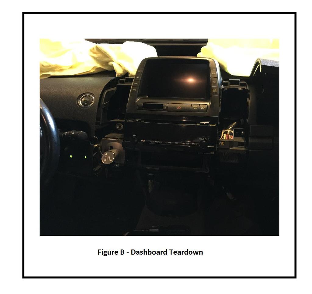
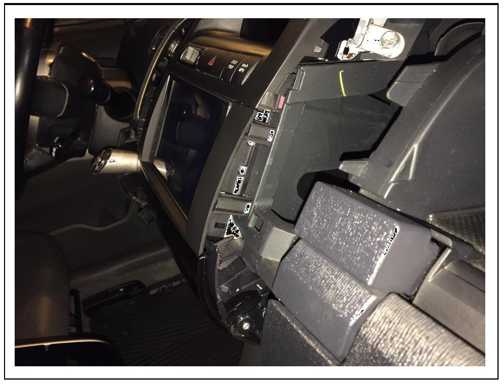
7 P a g e 6 Remove screw from the lower dash panel underneath the steering wheel beside the hood release latch. No Need to unplug anything again, just needs to be loose. Remove Left driver side Vent start by using soft plastic pry tool on the bottom of the vent, and pry upwards. Once loose, pull up and out, set down on towels on dashboard or towels on back seat carefully to avoid scratches. The clips will not break, do not worry if you have to pull hard but be careful and stop if you hear cracking and analyze with a flashlight to ensure you re doing it accurately. Remove screw from the bottom lining of vent hole. Pry outwards on lower dash piece surrounding the steering wheel, be careful with the last two clips around the steering wheel, they will be the toughest to pop out. However, you only need 1 clip on the outer left dash to come out and the two on the right side by the POWER button to pop out to allow for removal of the right side drivers vent to be removed. Pry upwards on the upper dash panel that includes the Power button, no need to unplug it, just make sure it s loose and moving freely. Cover Shift Lever with a towel to avoid scratches, then remove the vent in the same manner as the first far left vent, prying up from the bottom, then pulling up. Now, lift the center dash trim panel with the POWER button out of the way to allow clearance of the vent. UNPLUG the Parking button. Set Vent aside on towel on back seat. Remove the right vent around the stereo. Pry up from bottom and pull upwards until it comes out. Set aside carefully on towel. Figure B shows where you should be at this point:
8 P a g e 7
9 P a g e 8 Remove MFD (NAVIGATION SCREEN) Fold up a towel leaving at least 4-6 layers of cushion and place on top center portion of dash above the POWER button next to the vent gap. Remove two 10 mm bolts around Navigation/MFD Screen Pull outwards (it will be tough, but just be sure you re ready for the jolt it makes when popping it out of the clips) DO NOT unplug the MFD. Set on top of layered towel, the cables are long enough REMOVE FACTORY STEREO AND LOWER STEREO COMPONENTS Remove the two screws from the lower panel holding the cubby panel in place under the stereo. Pull outwards to unclip the panel and set aside. Remove Top Left and Right 10 mm bolts holding the stereo in place Remove the Bottom left bolt holding the stereo in place, then the right bolt. Pull outwards on the stereo until the clips release Unplug both harnesses connected to the factory stereo Bring the stock stereo to your designated workplace with your materials and electronics and newly made harness after.

10 P a g e 9 7. Prepare Stereo For Installation Take the stock stereo and remove the lower cubby Take the new Deck out of the box and mount the two mounting pieces included with the Metra B and be sure to mount it in the same place as the stock stereo. It is recommended to set them next to each other and compare and tweak until they are aligned in the same position as shown in Figure D
 One connector is for the TYTO-01 to plug into")
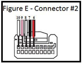
11 P a g e Install the Harness with ASWC-1 and TYTO-01 and Wire Taps As you will see, on the JBL head units there is two connectors (oppose to three on the non-jbl) One connector is for the TYTO-01 to plug into Connector #1 The other Connector is where you will add the Resistor and Wire taps Connector #2 Connector #2 & ASWC-1 Locate Pin 9 & 10, look closely, they are engraved in the connector. Connect one side of the Resistor Posi-Tap to Pin 10, and the other to Pin 9. Connect the Posi-Tap from the Black/Green Wire to PIN 8 Connect the Posi-Tap from the Green/Orange Wire to PIN 7 NOTE: Be sure you align the wire in the Posi-Tap in the middle of the connector and visually inspect it when tapping the wire to ensure it pierces directly through the middle. The stock OEM wires will not be harmed and only have holes afterword which can be covered with shrink wrap if you decide to reverse the installation process.

12 P a g e 11

13 P a g e 12 Complete resistor and ASWC-1 Installation and wire tap into Connector #2 GROUNDS In the middle of the two upper stereo frame bolts, there will be one 10 mm bolt in the middle, locate it and remove the 10 mm bolt. Connect the Posi-Tap from one end of the ground wire you created to PIN 6, leave the other end stripped The black wire from the ASWC-1 that you attached a ground wire and left one side stripped will now be utilized The Ground from the Micro Bypass that is stripped will now be utilized. Attach ALL 3 ground wires together and twist, then connect to a ground connector. Pull out on the plastic in front of the threading of the middle bolt and slip the round ground connecter behind the plastic panel. Re-Drive the bolt back into place. See image below for reference All your grounds are now ready, proceed to the next step

14 P a g e 13

15 P a g e 14 TYTO-1 Connection to Stock OEM Harness -Connect the TYTO-1 to the vehicles harness STEREO Auxiliary Cables In order to fit all Auxiliary Cable in a convenient place, especially when using an AppRadio with CarPlay enabled, you will need to drill a 1 Inch in Diameter hole in the side of the upper glove box facing the driver s side as shown in the images. You can always run them elsewhere, but I found that it was the best place since the Priuses glove box has an anti-slip mat preinstalled and it makes great use for a smartphone instead of mounting somewhere else. At the same time, your phone will charge as well and not fly or fall when braking or turning. Be sure to vacuum and wipe out the glovebox when you re done drilling. If your worried about doing irreversible damage to your glovebox, you can route the wires in the lower glove box, but remember you can always plug it with a grommet if you decide to reverse the installation. A Grommet can be placed inside the drilled hole before the wires are ran. But be aware that the HDMI cable barely fit so the whole would have to be larger, preferably up to 1.5 Inches

16 P a g e 15

17 P a g e 16 Connect the Deck harness to the back of the deck Connect the HDMI Cable Connect USB1 Connect USB2 Connect GPS Antenna Connect AUX Input Connect Microphone Connect Antenna IMPORTANT BE SURE TO CONNECT THE 3.5 mm jack from the ASWC to the remote wire on the back of the Deck. STOP - DOUBLE CHECK ALL CONNECTIONS TO MAKE SURE EVERYTHING IS CONNECTED BEFORE BOLTING THE NEW DECK DASH FRAME INTO PLACE

18 P a g e 17 Wiring Bolt stereo back into place starting on the top left, top right, then the bottom in the same order, be sure to leave the bolts partially untightened so you can get the Deck straight before the final tightening of the four 10mm bolts Run the GPS Antenna and Microphone to the Driver side vent closest to the window and be sure it is underneath all panels and on the inside of the dashboard snap connectors Run all Auxiliary connection Cables through drilled hole in upper glove box Place Apple AV Adapter and Lightning cable in their as well 9. GPS ANTENNA AND MICROPHONE MOUNTING GPS ANTENNA Run the GPS antenna wire down under the dash under the vent by the driver s side window Run it out all the way to the floor panel, then around the side. Then run it up into the corner of the dashboard and mount it as shown in the images using 3M Film and the under sticky metal panel (Sticky metal panel comes with the Pioneer AppRadio 4). IMPORTANT cut out a custom square of this sticky metal stuff to first stick onto the dash since the grooves in the dashboard will not allow the 3M to stick by itself Tuck the wires into the side until it is no longer visible Pull the excess wire through the Vent, then neatly zip tie it to the harness directly under the vent until it is tight and neat as shown in figure I below.

19 P a g e 18

20 P a g e 19
 Drilling the internals keeps the wire from being pinched Set aside Apply another cut square piece of the adhesive/metal plate Apply 3M to top side of metal, and")
21 P a g e 20 MICROPHONE Next to the dimmer switch, there is a removable blank button, remove it Drill out a slight half hole on the bottom Drill out the side of the Clip closest to the half hole you just drilled (inside the blank button) Drilling the internals keeps the wire from being pinched Set aside Apply another cut square piece of the adhesive/metal plate Apply 3M to top side of metal, and stick the microphone to it as shown Run wires through blank button holes you cut Adjust mic to proper position Place button back in with mic attached Pull excess microphone wire through the vent Zip tie it to the same place as previously done with the GPS wiring

22 P a g e TEST THE SYSTEM Place a towel back over the shift lever and reconnect the Parking Brake Button Reconnect the Negative Battery Terminal Press the POWER Button Watch everything turn on (MFD, Dash Lights, and Deck) If you have an iphone, plug it into USB1, and test CarPlay Use the Fade controls for the speakers and ensure every speaker is working Test the Steering Wheel Controls after 45 SECONDS after pressing the POWER button Volume Controls, Up, Down, Mode, and Voice Command for Siri should ALL Work Test microphone, GPS, and all functions related to CarPlay if applicable The Dashboard and MFD should NOT display ANY Error The Climate Controls should ALL work

23 P a g e 22

24 P a g e 23

25 P a g e 24 Climate control should work on both the MFD and the steering wheel, be sure to test both for full functionality If everything is working correctly then proceed to step 11 after POWERING OFF the vehicle and removing the Vent around the shifter If something is not working correctly, then analyze ALL CONNECTIONS in the wiring harnesses and dashboard components 11. PUT THE INTERIOR COMPONENTS BACK TOGETHER Now that everything works and everything is mounted properly, you can re-install all dash pieces in the reverse order. Start with placing the Metra Dash kit panel around the deck into the clip holes Reinstall the MFD Screen. Re-install the lower cubby panel under the new Deck Re-install the Vent with the shifter Clip the upper and lower dash around the steering column back together Re-install the lower panel under the lower stereo cubby with 12V in plug (remember to place the clip back into the right passenger side) Re-install the remaining vents

26 P a g e 25

27 P a g e 26

28 P a g e 27

29 P a g e 28
30 P a g e 29 THANK YOU FOR USING THIS MANUAL FOR YOUR INSTALL PLEASE ENJOY YOUR NEW SYSTEM! QUESTIONS? COMMENTS? CONTACT US AT K.CRUZ.INC@GMAIL.COM CRUZ INC 2015 DISCLAIMER: CRUZ INC & K.CRUZ disclaims any liability for ANY damage you may do to your vehicle as a result of following this installation manual. CRUZ INC disclaims ownership for any and all brand names and logos from all companies and manufacturer equipment used in this installation and mentioned in this manual. It is always recommended to have a professional install a new system in your vehicle, and this manual should not be used as a supplement for the installation manuals included with your components purchased as a part of this installation. CRUZ INC & K.CRUZ cannot guarantee success for every person using this
31 P a g e 30 manual, but we have always had success in our installations using these methods. INSTALL AT YOUR OWN RISK, ALWAYS FOLLOW ALL APPLICABLE SAFETY PRACTICES.
Chevy Equinox / GMC Terrain 2013-up (with color display) G
 G") INSTALLATION INSTRUCTIONS FOR PART 99-3308G Chevy Equinox / GMC Terrain 2013-up (with color display) 99-3308G KIT FEATURES ISO DIN radio provision with pocket ISO DDIN radio provision Painted gray to match
INSTALLATION INSTRUCTIONS FOR PART 99-3308G Chevy Equinox / GMC Terrain 2013-up (with color display) 99-3308G KIT FEATURES ISO DIN radio provision with pocket ISO DDIN radio provision Painted gray to match
B. Ford Fusion 2013-up
 99-5841B INSTALLATION INSTRUCTIONS Ford Fusion 2013-up KIT FEATURES ISO DIN radio provision with pocket ISO DDIN radio provision Integrated controls for info center Painted black Note: Does not support
Jeep Cherokee Latitude/Limited 2014-up
 Installation instructions for part 99-6526 REV. 5/23/2017 INST99-6526 KIT FEATURES ISO DDIN radio provision Included interface shows climate and menu info on the aftermarket radio screen. Painted scratch-resistant
CH. Ford Mustang
 99-5839CH INSTALLATION INSTRUCTIONS Ford Mustang 2010-2014 KIT FEATURES ISO DIN radio provision with pocket ISO DDIN radio provision Painted charcoal with a matte black center Touchscreen interface for
Nissan Maxima (with Technology Package) Nissan Maxima (with NAV) 2009 KIT FEATURES. ISO DIN radio provision with pocket...
 Nissan Maxima (with NAV) 2009 KIT FEATURES. ISO DIN radio provision with pocket...") 99-7633 INSTALLATION INSTRUCTIONS KIT FEATURES ISO DIN radio provision with pocket ISO DDIN radio provision Painted high gloss black KIT COMPONENTS A) Radio trim panel with climate controls B) Radio brackets
99-7633 INSTALLATION INSTRUCTIONS KIT FEATURES ISO DIN radio provision with pocket ISO DDIN radio provision Painted high gloss black KIT COMPONENTS A) Radio trim panel with climate controls B) Radio brackets
Harley-Davidson Street Glide, Electra Glide, Ultra and Limited models 2014-up
 INSTALLATION INSTRUCTIONS FOR PART 99-9700 APPLICATIONS Harley-Davidson Street Glide, Electra Glide, Ultra and Limited models 2014-up 99-9700 KIT FEATURES ISO DIN radio provision Included interface and
B. Ford Fusion 2013-up* *Visit metraonline.com for up-to-date vehicle specific applications.
 99-5841B INSTALLATION INSTRUCTIONS Ford Fusion 2013-up* *Visit metraonline.com for up-to-date vehicle specific applications. KIT FEATURES ISO DIN radio provision with pocket ISO DDIN radio provision Integrated
B. TABLE OF CONTENTS Dash Disassembly Kit Preparation...4 Kit Assembly...5 Axxess Interface Installation...6 Final Assembly...
 95-9324B INSTALLATION INSTRUCTIONS KIT FEATURES ISO DDIN radio provision Includes all necessary data interfaces, wiring harnesses, and antenna adapter, for a complete installation Includes components necessary
Tools Needed: 7mm Socket socket wrench socket extension interior removal tool wire cutter electical tape Wrangler Raxiom Navigation
 2007-2010 Wrangler Raxiom Navigation Contents: (1) - Raxiom Head Unit (1) - Headphone Jack With Wire (A) (1) - GPS Antennae With Wire (B) (1) - Amplifier Pre-Outs Wire Harness (C) (1) - External Microphone
Nissan Pathfinder (without NAV) (with color screen) HG
 (with color screen) HG") Installation instructions for part 99-7627HG Nissan Pathfinder 2013-2016 (without NAV) (with color screen) 99-7627HG KIT FEATURES ISO DIN radio provision with pocket ISO DDIN radio provision Painted to
Installation instructions for part 99-7627HG Nissan Pathfinder 2013-2016 (without NAV) (with color screen) 99-7627HG KIT FEATURES ISO DIN radio provision with pocket ISO DDIN radio provision Painted to
Chevrolet Camaro 2010-up S-LC
 INSTALLATION INSTRUCTIONS FOR PART 99-10S-LC APPLICATIONS Chevrolet Camaro 2010-up 99-10S-LC KIT FEATURES DIN and DDIN head unit provision Painted silver to match factory dash AXXESS Interface included
Ford Flex (without NAV) TABLE OF CONTENTS Dash Disassembly Kit Preparation...4 Kit Assembly KIT FEATURES
 TABLE OF CONTENTS Dash Disassembly Kit Preparation...4 Kit Assembly KIT FEATURES") 99-5842 INSTALLATION INSTRUCTIONS KIT FEATURES ISO DIN radio provision with pocket ISO DDIN radio provision Touchscreen display for climate and personalization features Center panel painted silver with
99-5842 INSTALLATION INSTRUCTIONS KIT FEATURES ISO DIN radio provision with pocket ISO DDIN radio provision Touchscreen display for climate and personalization features Center panel painted silver with
TOYOTA VENZA HANDS FREE BLU LOGIC Preparation
 TOYOTA VENZA 2009- HANDS FREE BLU LOGIC Preparation Part #: PT923-00111 Conflicts: JBL Audio NOTE: Part number of this accessory may not be the same as the part number shown. Kit Contents: For kits manufactured
CH. Ford Edge (with 4.2 screen)
") 99-5848CH INSTALLATION INSTRUCTIONS Ford Edge (with 4.2 screen) 2011-2014 KIT FEATURES ISO DIN radio provision with pocket ISO DDIN radio provision Touchscreen display for climate and personalization features
99-5848CH INSTALLATION INSTRUCTIONS Ford Edge (with 4.2 screen) 2011-2014 KIT FEATURES ISO DIN radio provision with pocket ISO DDIN radio provision Touchscreen display for climate and personalization features
HG. Chrysler Pacifica 2017-up* *Visit MetraOnline.com for up-to-date vehicle specific applications.
 99-6543HG INSTALLATION INSTRUCTIONS KIT FEATURES ISO DIN radio provision with pocket ISO DDIN radio provision Touchscreen display for climate and personalization features Painted high gloss black Note:
B. Ford F-150 (with 4.2 screen)
") 99-5846B INSTALLATION INSTRUCTIONS KIT FEATURES ISO DIN radio provision with pocket ISO DDIN radio provision Touchscreen display for climate and personalization features Integrated hazard button and passenger
99-5846B INSTALLATION INSTRUCTIONS KIT FEATURES ISO DIN radio provision with pocket ISO DDIN radio provision Touchscreen display for climate and personalization features Integrated hazard button and passenger
B. TABLE OF CONTENTS Dash Disassembly...2 Kit Preparation...3 Kit Assembly...4 Axxess Interface Installation...5 Final Assembly...
 95-9322B INSTALLATION INSTRUCTIONS BMW X5 (with MOST Amp) 2007-2013 Visit MetraOnline.com for more detailed information about the product and up-to-date vehicle specific applications KIT FEATURES ISO DDIN
Retains OnStar/OE Bluetooth Adjustable volume for chimes and OnStar Retains satellite radio Retains balance and fade Micro B USB updatable
 GMOS-LAN-034 INSTALLATION INSTRUCTIONS INTERFACE FEATURES Provides accessory power (12-volt 10-amp) Maintains the retained accessory power (R.A.P.) feature Can be used in non-amplified, or amplified models
B. TABLE OF CONTENTS Dash Disassembly...2 Kit Preparation...3 Kit Assembly...4 Axxess Interface Installation...5 Final Assembly...
 95-9317B INSTALLATION INSTRUCTIONS BMW 3 & 4 Series* (with NBT idrive, without MOST Amp) 2014-2016 F30, F31, F32, F33, F34, F36, F80, F82, F83 Visit MetraOnline.com for more detailed information about
CH. Ford Explorer (with 4.2 screen)
") 99-5847CH INSTALLATION INSTRUCTIONS Ford Explorer (with 4.2 screen) 2011-2015 KIT FEATURES ISO DIN radio provision with pocket ISO DDIN radio provision Touchscreen display for climate and personalization
99-5847CH INSTALLATION INSTRUCTIONS Ford Explorer (with 4.2 screen) 2011-2015 KIT FEATURES ISO DIN radio provision with pocket ISO DDIN radio provision Touchscreen display for climate and personalization
Mazda S
 INSTALLATION INSTRUCTIONS FOR PART 99-7523S KIT FEATURES Double DIN radio provision ISO DIN radio provision with pocket Painted silver Pre-wired ASWC-1 harness included (ASWC-1 sold separately) APPLICATIONS
Chevy Sonic 2012-up G
 INSTALLATION INSTRUCTIONS FOR PART 99-3012 APPLICATIONS Chevy Sonic 2012-up 99-3012G KIT FEATURES ISO DIN Head unit provision with pocket DDIN Head unit provisions Painted Gray to match factory finish
Ram 1500/2500/ up (with 8 touchscreen) B
 B") INSTALLATION INSTRUCTIONS FOR PART 99-6527B Ram 1500/2500/3500 2013-up (with 8 touchscreen) 99-6527B KIT FEATURES ISO DIN radio provision with pocket ISO DDIN radio provision Touchscreen display for climate
INSTALLATION INSTRUCTIONS FOR PART 99-6527B Ram 1500/2500/3500 2013-up (with 8 touchscreen) 99-6527B KIT FEATURES ISO DIN radio provision with pocket ISO DDIN radio provision Touchscreen display for climate
GMOS-LAN-034 GM LAN-11 OnStar interface
 Installation instructions for GMOS-LAN-034 GMOS-LAN-034 GM LAN-11 OnStar interface 2006-2012 Provides accessory power (12-volt 10-amp) Retains R.A.P. (retained accessory power) Can be used in non-amplified,
Ford F up CH
 INSTALLATION INSTRUCTIONS FOR PART 99-5834CH KIT FEATURES ISO DIN radio provision with pocket ISO DDIN radio provision Painted Charcoal Touchscreen display for climate and personalization features Ford
AVH-2330NEX AVH-2300NEX AVH-1330NEX AVH-1300NEX
 AVH-2330NEX AVH-2300NEX AVH-1330NEX AVH-1300NEX DVD RDS AV RECEIVER Installation Manual Connection Precautions Your new product and this manual Do not operate this product, any applications, or the rear
AFSI-02 SYNC INTERFACE INSTALLATION INSTRUCTIONS FORD SYNC INTERFACE * READ IMPORTANT WARNING ON PAGE 1 BEFORE ATTEMPTING ANY INSTALLATION
 FORD SYNC INTERFACE SYNC INTERFACE INSTALLATION INSTRUCTIONS * READ IMPORTANT WARNING ON PAGE 1 BEFORE ATTEMPTING ANY INSTALLATION The is designed to retain the features of the Ford Sync system allowing
Instructions for Front Midrange / Tweeter Installation in BMW 3 Series/M3 (E36)
") Disclaimer: Bavarian Soundwerks highly recommends professional installation of the products we sell. We provide these installation instructions free of charge as a guide to assist those customers who choose
Disclaimer: Bavarian Soundwerks highly recommends professional installation of the products we sell. We provide these installation instructions free of charge as a guide to assist those customers who choose
TOYOTA CAMRY HANDS FREE BLU LOGIC Preparation
 TOYOTA CAMRY 2008- HANDS FREE BLU LOGIC Preparation Part #: PT923-00111 Conflicts: JBL Audio, Factory Navigation NOTE: Part number of this accessory may not be the same as the part number shown. Kit Contents:
2010 Toyota Prius model II Head Unit Upgrade
 2010 Toyota Prius model II Head Unit Upgrade Monday, December 21, 2009 Disclaimer: Use this document and its contents at your own risk. Forward: Huge thanks to those members on Priuschat.com that forged
AFSI-01 SYNC INTERFACE INSTALLATION INSTRUCTIONS FORD SYNC INTERFACE * READ IMPORTANT WARNING ON PAGE 1 BEFORE ATTEMPTING ANY INSTALLATION
 FORD SYNC INTERFACE AFSI-01 SYNC INTERFACE INSTALLATION INSTRUCTIONS * READ IMPORTANT WARNING ON PAGE 1 BEFORE ATTEMPTING ANY INSTALLATION The AFSI-01 is designed to retain the features of the Ford Sync
Ford Mustang 2015-up CH. Table of Contents. METRA The World s best kits. metraonline.com. (with 4.2 screen)
") INSTALLATION INSTRUCTIONS FOR PART 99-5838CH Ford Mustang 2015-up Table of Contents (with 4.2 screen) Dash Disassembly...2-4 Kit Preparation...5-7 Kit Assembly 99-5838CH REV. 2/7/2017 INST99-5838CH KIT
INSTALLATION INSTRUCTIONS FOR PART 99-5838CH Ford Mustang 2015-up Table of Contents (with 4.2 screen) Dash Disassembly...2-4 Kit Preparation...5-7 Kit Assembly 99-5838CH REV. 2/7/2017 INST99-5838CH KIT
Honda Accord 2013-up B
 Installation Instructions for 99-7804B REV. 3/17/2015 INST99-7804B KIT FEATURES ISO DIN radio provision with pocket DDIN radio provision Painted two tone to match factory Retains factory color screen Honda
GMOS-LAN-012. GM LAN-29 Data Interface 2006-up* *Visit AxxessInterfaces.com for up-to-date vehicle specific applications.
 GMOS-LAN-012 INSTALLATION INSTRUCTIONS INTERFACE FEATURES Provides accessory power (12-volt 10-amp) Maintains the retained accessory power (R.A.P.) feature Can be used in non-amplified, or analog/digital
AX-JP901. Jeep Renegade Data Interface with SWC & Factory Display Retention 2015
 AX-JP901 INSTALLATION INSTRUCTIONS Jeep Renegade Data Interface with SWC & Factory Display Retention 2015 INTERFACE FEATURES Provides accessory power Designed for non-amplified models Provides NAV outputs
AX-ADVW01. Volkswagen Data Interface
 AX-ADVW01 INSTALLATION INSTRUCTIONS INTERFACE FEATURES Provides accessory power (12-volt 10-amp) Maintains the retained accessory power (R.A.P.) feature Provides NAV outputs (parking brake, reverse, speed
INSTALLATION INSTRUCTIONS JEEP 2011-UP JK SECURITY FULL CONSOLE #274
 INSTALLATION INSTRUCTIONS JEEP 2011-UP JK SECURITY FULL CONSOLE #274 PARTS CHECKLIST Tuffy Console #9 Left Front Mounting Bracket #10 Right Front Mounting Bracket #11 Electronics mounting bracket #12 Divider
OE Style Touch Screen Navigation
 2010-2014 OE Style Touch Screen Navigation Step 1 Begin by removing the shift knob on manual transmission equipped vehicles or the shifter trim bezel on an automatic car. Step 2 Open the center console.
B. Ford Focus (with 4.2 screen) 2015-up* *Visit MetraOnline.com for up-to-date vehicle specific applications.
 2015-up* *Visit MetraOnline.com for up-to-date vehicle specific applications.") 99-5843B INSTALLATION INSTRUCTIONS KIT FEATURES ISO DIN radio provision with pocket ISO DDIN radio provision Integrated controls for info center Includes Axxess interface and wiring Painted matte black
99-5843B INSTALLATION INSTRUCTIONS KIT FEATURES ISO DIN radio provision with pocket ISO DDIN radio provision Integrated controls for info center Includes Axxess interface and wiring Painted matte black
AVH-601EX AVH-600EX AVH-501EX AVH-500EX
 AVH-601EX AVH-600EX AVH-501EX AVH-500EX DVD RDS AV RECEIVER Installation Manual 2 Important safety information Rear visibility systems (backup cameras) are required in certain new vehicles sold in the
AX-ADGM01. GM Data Interface 2006-up* *Visit AxxessInterfaces.com for up-to-date vehicle specific applications.
 AX-ADGM01 INSTALLATION INSTRUCTIONS INTERFACE FEATURES Provides accessory power (12-volt 10-amp) Maintains the retained accessory power (R.A.P.) feature Provides NAV outputs (parking brake, reverse, speed
PART NUMBER: H630SSJ000. Kit Contents: A. Amplifier with Bracket (1) D. Badge (2) with push nuts (4)
 D. Badge (2) with push nuts (4)") Kit Contents: A. Amplifier with Bracket (1) D. Badge (2) with push nuts (4) E. Clip B. Harness (1) C. Cable tie (8) F. Mounting Hardware (2) G. Replacement Speaker (2) H. HVAC Duct extension (2) IMPORTANT:
Kit Contents: A. Amplifier with Bracket (1) D. Badge (2) with push nuts (4) E. Clip B. Harness (1) C. Cable tie (8) F. Mounting Hardware (2) G. Replacement Speaker (2) H. HVAC Duct extension (2) IMPORTANT:
Tutorial:Head Unit Installation
 Tutorial:Head Unit Installation From Tech Wiki : Nissan 350Z : Infiniti G35 : Nissan GT-R Here, I installed the Kenwood DDX7015 touch screen DVD system. I made this step-by-step tutorial to help those
U L T I M A T E R A D A R / L A S E R D E F E N S E S Y S T E M
 S m a r t e r Q u i e t e r M o r e A c c u r a t e U L T I M A T E R A D A R / L A S E R D E F E N S E S Y S T E M Installation Manual PASSPORT 9500ci Comes Complete Front Radar Receiver Miniature weatherproof
INSTALLATION INSTRUCTIONS
 INSTALLATION INSTRUCTIONS Accessory Application Publications No. AII 26042-26353 XM INTERFACE ODYSSEY EXCEPT EX-L WITH NAVI/RES Issue Date FEB 2004 PARTS LIST 8 Wire ties XM Radio Attachment P/N 08B15-S0X-100
AX-VL Volvo XC90 Data Interface with SWC * * For models with rear parking sensors
 AX-VL90042 INSTALLATION INSTRUCTIONS Volvo XC90 Data Interface with SWC 2004-2014* * For models with rear parking sensors INTERFACE FEATURES Provides accessory power Retains R.A.P. (retained accessory
Depress each tab as you pull the bezel off. The bezels are tight. L.H. shown.
 2013-2014 Ford Mustang V6 & Boss 302 Lower Valance Fog Light Kit Parts List: Quantity: Tool List: Fog light & bulb with bracket 2 Flat head & Phillips screwdriver Black bezels 2 Ratchet & Socket set OR
* * Inside Toyota Avalon. Tools Required IMPORTANT
 Revision 08/02/16 2013- Toyota Avalon IMPORTANT Before starting, compare items on your invoice with items received. Carefully check through packaging material. If any item is missing, please call Crutchfield
Essentials. Simple and Easy to Follow Installation Manual % Free Call! Expert Advice.
 Essentials Simple and Easy to Follow Installation Manual % Free Call! %800-745-5337 Expert Advice DVD Headrest JK Wrangler Installation Instructions Note: Be sure to read this entire instruction sheet
Tru-Billet Climate Control Knob Installation Instructions
 P/N S197-525-07 2007-08 Tru-Billet Climate Control Knob Installation Instructions Thank you for your purchase of SilverHorse Racing products. Please read all directions before beginning the installation.
Remove the 3-11mm nuts holding mirror on. Don t drop the nuts!
 2005-2012 Ford Mustang Puddle Lamp Kit Parts List: Quantity: Tool List: LED Lamps 2 Flat head screwdriver Seals 2 Ratchet & Socket set OR Nuts 2 Adjustable Wrench Wiring harness 1 Drill & 11/16 th bit
Please read thoroughly before starting installation and check that kit contents are complete.
 Rear Vision System Mirror Display 2013-Current Ram (Kit part number 1009-9518) Please read thoroughly before starting installation and check that kit contents are complete. Items Included in the Kit: Rear
AX-LR902. Land Rover Range Rover Evoque Data Interface with SWC & Factory Display Retention 2014* * For models with rear parking sensors
 AX-LR902 INSTALLATION INSTRUCTIONS Land Rover Range Rover Evoque Data Interface with SWC & Factory Display Retention 2014* * For models with rear parking sensors INTERFACE FEATURES Provides accessory power
Raxiom Factory GPS Rear Back-up Camera Kit (07-17 Wrangler)
") Raxiom Factory GPS Rear Back-up Camera Kit (07-17 Wrangler) Installation Time: 2.5-3Hrs Tools Required: 7mm Socket & Driver 10mm Socket 10mm Open end wrench Knife / Razor blade Zip-ties Wire Cutters Needle
Raxiom Factory GPS Rear Back-up Camera Kit (07-17 Wrangler) Installation Time: 2.5-3Hrs Tools Required: 7mm Socket & Driver 10mm Socket 10mm Open end wrench Knife / Razor blade Zip-ties Wire Cutters Needle
INSTALLATION INSTRUCTIONS
 INSTALLATION INSTRUCTIONS Accessory Application Publications No. SYSTEM 2005 ACCORD All 27511 (DX, LX) 2-AND 4-DOOR Issue Date AUG 2004 PARTS LIST Security System Attachment (LX): P/N 08E55-SDA-100A Unit
Toggle Button Kit. Installation Instructions MK5 / MK6 Golf, MK5 Jetta
 Toggle Button Kit Installation Instructions MK5 / MK6 Golf, MK5 Jetta Thank you for choosing the Double Apex Toggle Button kit. If you have any questions about the installation please do not hesitate to
INSTALLATION INSTRUCTIONS
 INSTALLATION INSTRUCTIONS Accessory USB ADAPTER Application 2014 INSIGHT Publications No. AII 50655 Issue Date OCT 2013 PARTS LIST USB Adapter Attachment Kit P/N 08B28-TM8-100A 6 mm Flange nut Control
Jeep Wrangler PSS-20WRA Sound System Installation Manual Model: Wrangler Unlimited Model Year:
 UNLIMITED 1/20 Jeep Wrangler PSS-20WRA Sound System Installation Manual Model: Wrangler Unlimited Model Year: 2007 2014 *Not compatible with factory amplified systems Jeep Model Year Wrangler Unlimited
TOYOTA tc HANDS FREE BLU LOGIC Preparation
 TOYOTA tc 2011- HANDS FREE BLU LOGIC Preparation Part #: PT923-00111 Conflicts: JBL Audio, Factory Navigation NOTE: Part number of this accessory may not be the same as the part number shown. Kit Contents:
Installation Instructions for Chevrolet Colorado, GMC Canyon, LT, Z71, With Factory Fog Lights
 Installation Instructions for 2015-2018 Chevrolet Colorado, GMC Canyon, LT, Z71, With Factory Fog Lights This kit is designed to allow use of your factory fog light operation along with an addition auxiliary
RZ3-5A Polaris RZR XP 1000 & 900 SSV Works 5 Speaker Audio Kit
 RZ3-5A Polaris RZR XP 1000 & 900 SSV Works 5 Speaker Audio Kit pg 2 Disassembly, Wire and Amplifier Plate Installation pg 9 Glovebox Subwoofer Installation pg 13 Kick Panel Speakers Installation pg 25
TOYOTA im INTERIOR LIGHT KIT Preparation
 Preparation Part Number: PT922-12170 Kit Contents Item # Quantity Reqd. Description 1 1 Main Wire Harness 2 1 Switch 3 1 Switch Header 4 1 ECU 5 1 ECU Bracket 6 1 Hardware Kit 7 1 Instruction Card 8 1
B. Land Rover LR Visit MetraOnline.com for more detailed information about the product and up-to-date vehicle specific applications
 95-9405B INSTALLATION INSTRUCTIONS Land Rover LR4 2010-2016 Visit MetraOnline.com for more detailed information about the product and up-to-date vehicle specific applications KIT FEATURES ISO DDIN radio
Installation of Auto Meter Cobalt Boost/Vacuum Gauge:
 Installation of Auto Meter Cobalt Boost/Vacuum Gauge: Fitment: All 79-14 models. This installation was completed on a 2004 Mustang GT, and should be identical for all 1999-2004 model Mustangs. Time needed:
INSTALLATION INSTRUCTIONS
 Rear Vision System Tailgate Emblem Camera Mirror Display 2009-Current Ford F-150 and 2010-Current Super Duty (Kit part number 1008-9527) Kit Contents: Mirror Tailgate Emblem Mount with Camera Interior
INSTALLATION INSTRUCTIONS
 INSTALLATION INSTRUCTIONS Accessory Application Publications No. All 12035 SYSTEM 2012 RIDGELINE Issue Date NOV 2011 PARTS LIST Security System Attachment Kit: P/N 08E55-SJC-101 Flange bolt Unit bracket
Ford Mustang V6 OEM-Style Fog Light Kit Parts List: Quantity: Tool List:
 2015-2017 Ford Mustang V6 OEM-Style Fog Light Kit Parts List: Quantity: Tool List: LED Foglights/ Bezels 2 Flat head & Phillips screwdriver (if you ordered part#3600) Ratchet & Socket set OR Wiring harness
PART NUMBER: H630SXC001. Kit Contents: A. Amplifier with Bracket (1) D. Badge (2) with push nuts (4)
 D. Badge (2) with push nuts (4)") Kit Contents: A. Amplifier with Bracket (1) D. Badge (2) with push nuts (4) E. Clip B. Interface / Power Harness (1) C. Cable tie (8) F. Mounting Nuts (2) G. Replacement Front Speaker (2) H. Badge mounting
Kit Contents: A. Amplifier with Bracket (1) D. Badge (2) with push nuts (4) E. Clip B. Interface / Power Harness (1) C. Cable tie (8) F. Mounting Nuts (2) G. Replacement Front Speaker (2) H. Badge mounting
INSTALLATION INSTRUCTIONS
 INSTALLATION INSTRUCTIONS Accessory Application Publications No. in- ENTERTAINMENT SYSTEM 2004 TSX BII 24811 Issue Date APRIL 2003 PARTS LIST Attachment Kit P/N 08B23-SDA-101A Monitor bracket harness FM
AX-LR903. Land Rover Range Rover Evoque (with M.O.S.T. 25 amplifier) Data Interface with SWC & Factory Display Retention
 Data Interface with SWC & Factory Display Retention") AX-LR903 INSTALLATION INSTRUCTIONS Land Rover Range Rover Evoque (with M.O.S.T. 25 amplifier) Data Interface with SWC & Factory Display Retention 2012-2014 INTERFACE FEATURES Provides accessory power Retains
AX-LR903 INSTALLATION INSTRUCTIONS Land Rover Range Rover Evoque (with M.O.S.T. 25 amplifier) Data Interface with SWC & Factory Display Retention 2012-2014 INTERFACE FEATURES Provides accessory power Retains
AX-HYKIA2-SWC. Hyundai Data Interface with SWC
 AX-HYKIA2-SWC INSTALLATION INSTRUCTIONS Hyundai Data Interface with SWC 2012-2016 INTERFACE FEATURES Provides NAV outputs (parking brake, reverse, speed sense) Retains audio controls on the steering wheel
RZ3-5K Polaris RZR XP 1000 & 900 Kicker 5 Speaker Audio Kit
 PO H PWER PO 5 O KIT I E D U A S A TS S I R LA R Z R R O SP pg 2 pg 9 pg 13 pg 25 pg 29 Disassembly, Wire and Amplifier Plate Installation Glovebox Subwoofer Installation Kick Panel Speakers Installation
Ford RSE/SYNC/THX retention interface 2007-up
 INSTALLATION INSTRUCTIONS FOR PART AX-ADFD100 AX-ADFD100 Ford RSE/SYNC/THX retention interface 2007-up FEATURES Provides accessory (12-volt 10-amp) Retains R.A.P. (retained accessory power) Used in amplified,
WARNING WARNING WARNING. English Quick start guide CAUTION CAUTION. Installation Precautions
 English Quick start guide Symbol Identification This manual uses symbols and icons to indicate safety precautions and concerns during the installation procedure. Be sure to carefully read and understand
GMOS-LAN-02 GM LAN 29 Amplified OnStar Interface 2006-up
 M4 M5 M3 ISO 6 2.5 1.5 INSTALLATION INSTRUCTIONS FOR PART INSTGMOS-LAN-02 GMOS-LAN-02 GM LAN 29 Amplified OnStar Interface 2006-up APPLICATIONS See inside front cover KIT FEATURES Provides accessory (12-volt
Installation Instructions for the Plug & Play Remote Start Package (EVOCHR4)
") T6002 v1.1 02/2013 Installation Instructions for the Plug & Play Remote Start Package (EVOCHR4) For CHRYSLER Town & Country 2008-2012 Review the remote start installation manual for safety instructions!
T6002 v1.1 02/2013 Installation Instructions for the Plug & Play Remote Start Package (EVOCHR4) For CHRYSLER Town & Country 2008-2012 Review the remote start installation manual for safety instructions!
GM Class-2 data interface
 GMOS-014 INSTALLATION INSTRUCTIONS INTERFACE FEATURES Provides accessory power (12-volt 10-amp) Maintains the retained accessory power (R.A.P.) feature Can be used in non-amplified, or analog/digital amplified
Installation Instructions Z-Gate Shifter
 Installation Instructions Z-Gate Shifter Part Number 80681 1998, 2001 by B&M Racing and Performance Products The B&M Z-Gate shifter can be used in vehicles equipped with most popular three speed automatic
TOYOTA RAV4/HV INTERIOR LIGHT KIT Preparation
 Preparation Part Number: PT413-42130 Kit Contents Item # Quantity Reqd. Description 1 1 Wire Harness 2 3 Hardware Bag Contents Item # Quantity Reqd. Description 1 20 Cable Tie 2 2 Scotchlok 3 2 Foam Pad
VX7010. DVD / NAV / SiriusXM-Ready / Built-in Bluetooth / Pandora Link Compatible with iphone /Compatible with ipod / USB / Aux In INSTALLATION GUIDE
 VX7010 DVD / NAV / SiriusXM-Ready / Built-in Bluetooth / Pandora Link Compatible with iphone /Compatible with ipod / USB / Aux In INSTALLATION GUIDE What s in the Box The following items are supplied with
GENUINE PARTS INSTALLATION INSTRUCTIONS
 GENUINE PARTS INSTALLATION INSTRUCTIONS 1. 2. 3. 4. DESCRIPTION: APPLICATION: PART NUMBER: KIT CONTENTS: Accent light Kit Pathfinder 999F3 XZ000 - Accent Lighting Kit. Item QTY Description Service Part
Contents. TCS/ Driver Mod Installation Manual
 Contents Introduction... 1 TCS Packing List... 3 Tools Needed for Installation... 4 How to Properly Solder... 5 Soldering Standard Butt Connection... 5 Soldering T Connection... 6 How to Properly Crimp...
Signal Mirror Installation Instructions
 Signal Mirror Installation Instructions Ford F-250 to F-750 Pick-Up, Super-Duty 1998-2007 Trailer Tow Mirror Ford Excursion XLT/Limited 2000-2002 Trailer Tow Mirror Ford Excursion (all models) 2003-2005
TOYOTA TACOMA HANDS FREE BLU LOGIC Preparation. Item 5 Item 6 Item 7 Item 8. Item 4. General Applicability Note: Recommended Tools
 TOYOTA TACOMA 2008- HANDS FREE BLU LOGIC Preparation Part #: PT923-00098 Conflicts: JBL Audio, Factory Navigation Kit Contents: NOTE: Part number of this accessory may not be the same as the part number
I want to try my hand here at doing a TacoBill write up so here it goes.
 Here is part 3 of my tutorial for the conversion of my Shaker 1000 to the Kenwood DNX7100 Navigation / Head Unit. With the 7100, my new system will include the Kenwood I-pod Adapter (P.I.E. KNW/USB-AV),
INSTALLATION INSTRUCTIONS
 INSTALLATION INSTRUCTIONS Accessory Application Publications No. CD CHANGER ATTACHMENT KIT 2005 CIVIC SI AII 27936 Issue Date AUG 2004 PARTS LIST CD Changer Attachment Kit (sold separately): P/N 08B26-S5T-100
INSTALLATION INSTRUCTIONS
 INSTALLATION INSTRUCTIONS FUEL SURGE TANK INSTALL KIT Honda S2000 Document# 19-0063 Support: info@radiumauto.com WARNING: DO NOT SMOKE WHILE WORKING ON FUEL SYSTEMS. KEEP SPARKS AND OPEN FLAMES AWAY FROM
INSTALLATION INSTRUCTIONS FOR PART INSTGMOS-LAN-03. GMOS-LAN-03 GM LAN 11 Non-amplified OnStar APPLICATIONS. See inside front cover KIT FEATURES
 M4 M3 M5 ISO 6 2.5 1.5 INSTALLATION INSTRUCTIONS FOR PART INSTGMOSLAN03 GMOSLAN03 GM LAN 11 Nonamplified OnStar Interface 2006up APPLICATIONS See inside front cover KIT FEATURES Provides accessory (12volt
INSTALLATION INSTRUCTIONS
 INSTALLATION INSTRUCTIONS Accessory Application Publications No. SYSTEM ACCORD 2-DOOR (LX/EX L4, LX V6) AII 25749 Issue Date FEB 2004 PARTS LIST Double-sided adhesive tape XM Radio Attachment Kit : P/N
Toyota RAV up
 REV. 2/27/2014 INST99-8217 INSTALLATION INSTRUCTIONS FOR PART 99-8217 APPLICATIONS See application list inside Toyota RAV 4 2006-up 99-8217 KIT FEATURES DIN radio provision with pocket ISO DIN radio provision
TOYOTA COROLLA ILLUMINATED DOOR SILLS Preparation
 Preparation Part Number: PT942-02140 Kit Contents Item # Quantity Reqd. Description 1 1 Illuminated Scuff plate, Front Right Hand 2 1 Illuminated Scuff plate, Front Left Hand 3 1 Door Scuff plate, Rear
Toggle Button Kit. Installation Instructions
 Toggle Button Kit Installation Instructions Thank you for choosing the Double Apex Toggle Button kit. If you have any questions about the installation please do not hesitate to email us at support@doubleapex.co.
INSTALLATION INSTRUCTIONS INFINITI CELLPORT UNIVERSAL HANDS FREE SYSTEM
 INSTALLATION INSTRUCTIONS 1. DESCRIPTION: INFINITI CELLPORT UNIVERSAL HANDS FREE SYSTEM 2. APPLICATION: 2002 Q45 3. PART NUMBER: 948T3CELLR95 (VPC) or 999Q2TN000 (PDC) 4. TOOLS REQUIRED: a. Loctite 242
Step #1 From your spool of 18 gauge primary wire, cut between 11 and 21 three inch strips of wire. You will only need 11 for the ROV, but it is good t
 How to make a ROV! Step #1 From your spool of 18 gauge primary wire, cut between 11 and 21 three inch strips of wire. You will only need 11 for the ROV, but it is good to have extras. Using the wire cutter,
INSTALLATION INSTRUCTIONS
 Rear Vision System Liftgate Emblem Camera Mirror Display 2009-2012 Ford Flex (Kit part number 1008-9527) Kit Contents: Mirror Liftgate Emblem Mount with Camera Interior (shorter) Harness Chassis (longer)
General Applicability Note: Recommended Tools. Personal & Vehicle Protection Safety Goggles Seat Covers Floor Covers Special Tools. Installation Tools
 TOYOTA HIGHLANDER/HIGHLANDER HV 2008- Preparation Part #: PT923-00111 Conflicts: JBL Audio, Factory Navigation NOTE: Part number of this accessory may not be the same as the part number shown. Kit Contents:
Installation Instructions - ECS Tuning Vent Pod Vacuum/Boost Gauge Kit
 Installation Instructions - ECS Tuning Vent Pod Vacuum/Boost Gauge Kit This tutorial is provided as a courtesy by ECS Tuning. Part Number (also available as steering wheel mounted kit ES2593248) for VW
2016 HONDA 1000 Pioneer PN 3102 Turn signal / horn kit rev nc
 2016 Honda 1000 Pioneer STOP - THIS KIT IS DESIGNED SPECIFICALLY FOR 2016 HONDA 1000 PIONEER IF YOUR MACHINE IS NOT THIS MODEL DO NOT PROCEED. THIS KIT DOES NOT WORK ON THE PIONEER 500 nor 700 S. Contact
2010-Up Prius HB Navigation speedlock override installation guide.
 2010-Up Prius HB Navigation speedlock override installation guide. Dash disassembly Dash disassembly are the same for 2010, 2011, and 2012 Prius Hatch Back. The following is a 2010 Prius III. Remove the
SALEEN SPEEDLAB BOOST AND WATER TEMPERATURE GAUGE POD KIT
 = SALEEN SPEEDLAB BOOST AND WATER TEMPERATURE GAUGE POD KIT INSTALLATION MANUAL: 2005-09 Mustang 4.6L 3V P/N: 10-8002-C12000B KIT P/N: 10-2903-B11511* Saleen Performance, Inc. 1225 East Maple Rd. Troy,