Pajero flashing light fix
|
|
|
- Lambert Woods
- 6 years ago
- Views:
Transcription
1 Pajero flashing light fix Pajero 4WD Flashing Light Fix and Troubleshooting last updated 15th Sept Many Pajero's owners at one time or another face is the dreaded 4x4 Super Select flashing light problem. It only takes a small amount of crud in the wrong place to upset the system so pays to acquaint yourself with it if you want to fix it yourself. NOTE: This article is based on a gen 2.5 PETROL RHD vehicle, Also please note there are some differences between some models/engines - so your mileage may vary! Flashing super select 4wd lights most often occur when the front differential automatic disconnect is not engaging /dis-engaging when you select/deselect 4x4 drive. Causes are: - front differential sensor switch is damaged or faulty - actuator rod/shaft jammed / seized (perhaps sand/mud/dirt) - vacuum lines leak/popped off fittings - vacuum solenoid valves (2no.) either maybe faulty - electrical wiring connection issue (ecu/solenoids/switch) - combination of the above From the Pajero forums it is clear that another common problem is flashing lights after repair work, for example after installing a new gearbox, or even a new radio. Radio Installation READERS TIP **** If you have just installed or repalced your radio/cassette/dvd player and you experience a new flashing light problem, check that you have not damaged or pulled a wire from the 4wd ecu (blue box) which is located just below the radio opening. Other problems, for example the orange flashing light is also covered below. How it works It helps troubleshooting if you understand how the system should work. Pajero's have a four wheel drive system that allows the driver to engage 2 or 4wd, The rear differential is always driven, selecting 4wd engages the front differential free wheel, using a vacuum powered system. The transfer gearbox (4wd) is mechanical (1998 GDI 3.5) so the selected gear is just that. Whatever the position of the transfer gearbox stick that is the gear you are in, it is a mechanical function. The status of the system is indicated on the drivers console i.e. super select panel, however most often problems occur causing flashing lights, because there is a discrepancy between engaging/dis-engaging mechanism on the front differential and the transfer gearbox (tcase) gearstick position.
2 Lights At ignition, in 2wd, the bottom pair of green lights are lit and stay lit constantly, because these lights are lit constantly, failure usually means a blown bulb(s). The top pair of green lights flash briefly at startup but that is just an ECU start up check. If 4wd is properly selected and all the sensors are playing nicely, all four green lights are lit, and should not be flashing. The main components of the system we need to look at are: - super select light display - Front differential - Actuator - Actuator shaft (and boot) - Position sensor (the manual calls it the Free wheel engage switch) - Vacuum control solenoid valves (x2) - Vacuum piping (rubber and steel tubing) - Vacuum tank (accumulator) - 4WD ECU (electronic control unit) - centre differential - transfer gearbox Troubleshooting Most often the flashing light problem is an easy fix, primarily it happens because the 4wd system has not been regularly used. The 4wd must be used regularly and exercised to keep it in good working order. Assuming it's a Mk 1/2, the green lights are flashing because the system thinks that the front axle freewheel unit is still engaged and is trying to disengage it (or vice versa). The system is operated via vacuum created by running engine (for petrol models) and is controlled by switches and electric solenoid valves. The solenoid valves on the bulkhead in front of the driver typically near the master cylinder. In turn they are connect to the actuator on the front axle by a mixture of steel and rubber piping. Once engaged (or disengaged) the position is verified by the free wheel sensor switch. Fixing This list should help you track down and the problem fault. Sometimes something simple, such as reversing a few metres helps dis-engagement with wheels straight helps too. If reversing doesnt solve the problem you probably have a problem that needs further investigation. Basics Check your fluids. Check the transfer box oil and front differential oil levels. Remove the top filler plug, both should be filled to the level of the bottom of the fill hole. Any foul/burnt smell gritty texture indicates the oil is spent and an oil change is needed. Identify the correct oil from your manual. It is a good idea to change the fill and plug washers at the same time. On mine, when the diff gets hot oil leaks from the fill plug (another thing to add to my things to do list).

3 Tyres Double check that all your tyres are the exactly same size and equal pressures. Slightly different tyre size / uneven wear may prevent correct engagement/dis-engagement. Vacuum Solenoid Valves A solenoid valve is a fancy term for an electrically controlled valve, in this case controlling vacuum to the Front differential actuator. On RHD drive models, the vacuum control solenoids are mounted near the top of the inner wheel tub, near the master cylinder. Vacuum is needed both to open, and close the actuator. Each typically identified with a blob of paint, yellow and blue. (see picture). Electronic signals from the transfer box, to the gearbox ECU govern the operation of solenoids that control the vacuum feed to open and close the actuator located on the front differential. The vacuum line with yellow strip, just visible in picture, connects to the solenoid with yellow paint blob, and in turn connects to front differential actuator. Same with the blue striped hose connecting to the solenoid with the blue blob of paint. - Check that both solenoids are not sticking and operate correctly. - Check the electrical resistance, should be approx. 39/45 ohms (Haynes states 45 ohms) - Check the harness connection, apply electrical contact cleaner to clean connectors Mounted on the cross member, near the front differential is a vacuum storage vessel, or acculumator. It is about the size of a tin of baked beans. worth checking for leaks, rust, lose connections, etc.
.")
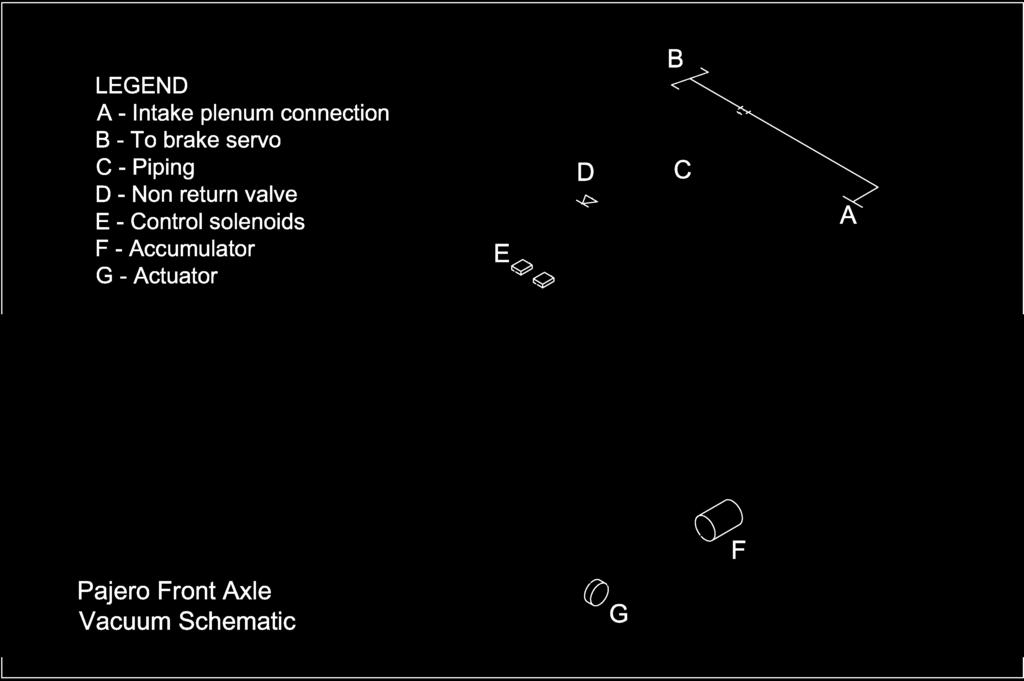
4 If you are greeted with flashing lights upon start up the vacuum accumulator (can) is unable to hold a vacuum, leaking or damage. Repair or replace. Also check that the vacuum line non-return valve is not leaking, causing accumulator to leak into the plenum overnight (refer to vacuum schematic drawing). Vacuum Solenoids - top of wheel tub near master cylinder Actuator and shaft Mount on the front differential, the actuator and shaft (covered with rubber boot) should be clean and free. Grease the actuator shaft under the rubber boot - they can seize and give a permanent flashing lights. The actuator is circular shape, about 50mm in diameter. Find someone you trust, lie under the car with the engine running while the "trusted" driver moves the transfer gear box (t-case) lever in and out of 4wd - you should see the shaft move. If it is not moving is probably seized from lack of use, carefully pull back the rubber boot and get some grease on the actuator rod. Try and slide it - it should move fairly easily if you jack a wheel and turn it a bit. If the shaft still doesn't move freely, pull each vacuum connection, and test if one, or other is sucking! (wise to ensure that the person behind the wheel knows what they are doing! - handbrake applied and auto in Park of course).
 D - Differential (front) E - Axle casing F - Crossmember Front Differential")
5 Key for images: A - Actuator B - Boot (covering actuator shaft) C - Vacuum can (about the size of a tin of baked beans) D - Differential (front) E - Axle casing F - Crossmember Front Differential Actuator
.")
6 Free Wheel Engage Switch When change 2wd to 4wd and vice versa, the actuator moves the actuator shaft, and its position is monitored by the free wheel engage switch. If the actuator is moving and the shaft is free, then the next check is the free wheel engage switch. It either needs replacing or cleaning (bad connection). This is located above the actuator shaft and if you remove your bashplates can see it clearly. To test continuity, whilst in 4wd, and igintion off, link across the connector. Upon restart if the flashing has stopped this confirms the wiring from the connector to the ecu is intact and the switch needs work (don't forget to remove the link and reinstate afterwards). Key for images: A - Actuator B - Boot (covering actuator shaft) C - Vacuum can (about the size of a tin of baked beans) D - Differential (front) E - Axle casing F - Crossmember
7 Vacuum Piping The vacuum piping comprises a combination of steel tube and rubber hoses bascially routed from the engine through the solenoid valves to the actuator. The piping might be leaking, disconnected or perished. Also it is easy to miss reconnecting if you have just done other work in that area (been there done that!). The non-return valve may also be faulty. You need to make sure that all the vacuum piping and hoses, and all connections are good. And don't forget without a hand vacuum pump the engine needs to be running to create the vacuum. To help trace any leakage: - Inspect the piping it might be damaged, leaking, spilt, cut, missing or perished. - Temporary swap over the vacuum hoses (yellow and blue stripe outlet from solenoid valves) if lights stop flashing, the fault is either yellow stripe or blue stripe tubing. Replace hoses to orginal position and track pipe leakage. A hand vacuum pump is really handy since a vacuum leak can be difficult to identify. - Test for continuity/blockage of piping. use a hand vaccum pump if available or alternately blow through disconnected pipe with helper underneath. If you identify a leak or disconnected pipe just reconnecting may not be sufficient to solve the problem since dust and dirt will have been sucked into the soleniod valve. Vacuum piping schematic diagram (pdf) Click here for vaccum piping schematic diagram (PDF format 1 page) Front axle (viewed from the front, beneath the radiator)
8
 D - Differential (front) E - Axle casing F - Crossmember Automotive Hand Vacuum")
9 Key for images: A - Actuator B - Boot (covering actuator shaft) C - Vacuum can (about the size of a tin of baked beans) D - Differential (front) E - Axle casing F - Crossmember Automotive Hand Vacuum Pump

10 Very useful tool to check vacuum piping. Centre Differential - Orange flashing light The transfer box (t-case) houses the centre differential, permitting drive to both front and rear wheels. On the super select panel it is represented as the central orange colour lamp, it is labelled "C/D Lock" The manual I have indicates that there is a switch connector, from the centre diff, with a yellow/blue wire (which then changes to brown/black) and connects to the 4x4 ECU. If you have different year, or a rear diff locker the wiring is a bit more complex. If you have the orange flashing light it is most probably an electrical issue with the centre differential detent switches on the transfer gear box (t/case), possibly a broken wire or fouled switch, could also be a poor connection due to mud/etc. There are five centre differential detent switches on the t/case for checking and inspection.
11 Vacuum Tank If you lights flash furiously even before firing up your engine, it most likely a problem with the vacuum accumulator or the non-return valve (refer to piping). The acculumator is a small vacuum tank, to "store" or retain vacuum, it looks like a small tin can, about the size of a can of baked beans (the universal size guage) and it is located just behind the front differential with vaccum pipe connection. Check the connection is secure, and tank itself is undamaged. Use hand vacuum pump if available to test for leakage. On older models check for rust, if you are sure the tank is intact, perhaps add a coat of hammerite paint or equal. DONT paint or use any solvents until you are sure the can is sound, otherwise any weakness would allow contamination to be sucked into the vacuum system. Transfer Gear box (t-case) The wiring from the switches on the top of the transfer gearbox can perish/harden over time and have a tendency to break. Treat them with care! Check for wiring for clean connections, continuity and possible short circuit. Where possible clean connectors with electrical contact cleaner or equal. transfer gearbox (t-case) sensor switches locations A Wiring Diagram I was asked for a wiring diagram, so there is link below. However, you have to be careful different models/years have different colour wiring! click here for wiring diagram (appox 110k)
12 Document1
13 4WD ECU Very rarely the 4WD Electronic Control Unit (ECU) located behind the dash is faulty. I'd re-check all above first, and try to swap with a known, working ECU to confirm the ECU fault before replacement $$$$
Wiring checks below assume the vehicle is in reverse, secured so it won't roll, and key is on so backup lights are illuminated:
 Reverse Lockout Troubleshooting The way that the backup solenoid works is: When the backup lights are lit on your tow vehicle, 12 volt power should come down the blue wire through the trailer connector
Connecting the rear fog light on the A4 Jetta, while keeping the 5 Light Mod
 Connecting the rear fog light on the A4 Jetta, while keeping the 5 Light Mod DISCLAIMER: I'm human and make mistakes. If you spot one in this how to, tell me and I'll fix it This was done on my 99.5 Jetta.
GLOVE BOX CHECK IT GUIDE
 GLOVE BOX CHECK IT GUIDE When it comes to road safety, one thing you can control is proper maintenance of your vehicle. Keep this simple guide in your glove box & use it to complete quick, regular checks
The Axles, Differentials And...Those Swivels!
 The Axles, Differentials And...Those Swivels! There are several different types of differential fitted to Series Landies: broadly, the Rover type differential, the Salisbury type differential, and the
Smart Opener Retrofit by Richard Bevan (bimmerfest riku2)
") Smart Opener Retrofit by Richard Bevan (bimmerfest riku2) Document history V 1.0 02.04.2015 Document created. Introduction This document tells how to retrofit the smart opener to a 2011 BMW 5 series (F10).
Smart Opener Retrofit by Richard Bevan (bimmerfest riku2) Document history V 1.0 02.04.2015 Document created. Introduction This document tells how to retrofit the smart opener to a 2011 BMW 5 series (F10).
Manual Where Do I Get Cars Need Transmission Fluid
 Manual Where Do I Get Cars Need Transmission Fluid This image compares the color of new transmission fluid to burnt fluid. be times when you need to get a transmission flush, in order to help protect your
Troubleshooting of the LubeTech Grease System
 Troubleshooting of the LubeTech Grease System February 2009 The LubeTech grease system is designed to be a preventative maintenance system that will extend the life of your bearings that are connected
SOME BASICS OF TROUBLESHOOTING
 SOME BASICS OF TROUBLESHOOTING DICK RANDALL I decided to pull these ideas together because I have spent plenty of hobby time figuring out things that did not work or that needed repair. This process and
Sunbeam Alpine Series III, IV, and V Fuel & Temperature Gauges by Michael Hartman and Thomas Hayden Version 1.4 May 9, 2018
 Sunbeam Alpine Series III, IV, and V Fuel & Temperature Gauges by Michael Hartman and Thomas Hayden Version 1.4 May 9, 2018 The Circuit Illustration 1: Temperature & Fuel Gauge Circuits (Series V) Example
Phone: Fax: ILD Series. Troubleshooting: ILD Column Lift
 15939 Piuma Avenue Cerritos, CA 90703 ILD Series Troubleshooting: ILD Column Lift Table of content: Page 1) Gate overview...2 2) Single Motor Setup overview. 3 3) Dual Motor Setup overview....4 4) Gate
INSTALLATION MANUAL AP60B INSTALLATION MANUAL
 INSTALLATION MANUAL 2. TOOLS REQUIRED The following is a list of tools required to properly install the cruise control. While this unit may be installed without some of the tools listed, it is recommended
Another CJ picture guide to replacing the key cylinder in a non-tilt steering column
 Another CJ picture guide to replacing the key cylinder in a non-tilt steering column by John Strenk Well I'm sure it's happened to all of us one time or another. You park your jeep and go to turn off your
Another CJ picture guide to
 Another CJ picture guide to replacing the key cylinder in a non-tilt steering column by John Strenk Well I'm sure it's happened to all of us one time or another. You park your jeep and go to turn off your
1 of 7 5/25/ :14 AM
 Home See What Fits Your Vehicle Towing Cargo Accessories Trailer Trim Manufacturers customer service view cart Subscribe to newsletter or feed Filter Videos Trailer Wiring Diagrams Articles about Wiring
VAGABOND S HANDBOOK TRANSMISSION
 03/24/07 TRANSMISSION Transmission won t engage into Gear This is caused usually by too low a Voltage to get into the ECM. This unit requires a minimum of 9VDC in order to operate at all. Almost all erratic
READ BEFORE STARTING PLEASE INSTALLATION! User Manual
 PLEASE READ BEFORE STARTING INSTALLATION! User Manual Contents 1 Scope of delivery3 2 Overview of the RaceChip 4 3 Installation 5 4 Fine tuning 14 5 Trouble Shooting 16 6 Contact 20 Overview and explanation
Multi-colour LED Status Light - using it as a diagnostic tool:
 All J+J electric actuators are tested prior to shipping. Most issues are site related, we hope that you will find a solution to your problem in this guide. If not, please contact us for support. Multi-colour
Lincoln Mark VII T5 Swap Version submitted by 5.0 bird
 Lincoln Mark VII 1984-1989 T5 Swap Version 20070611 submitted by 5.0 bird I've decided to make an article to assist with the T5 swap for the 84-89 Mark VIIs, since I was just in there because my DOA didn't
1 of 2 9/4/ :27 AM
 Ford Mustang IAC IAB - Solving your idle problems http://www.muscularmustangs.com/iac.php 1 of 2 9/4/2010 10:27 AM Solving idle problems part 1 - Cleaning your IAC Does your idle rise and fall over and
SMART DRIVE ELECTRONIC WASHING MACHINE
 SMART DRIVE ELECTRONIC WASHING MACHINE MODEL GWL08US Service Supplement to be used in conjunction with GWL03US Service Manual Part Number PM912 Fisher & Paykel Appliances Inc 27 Hubble, Irvine, California,
How to fit the remote parking heater module
 How to fit the remote parking heater module The function of this project is to convert a standard fuel burning heater on the diesel models of the Rover 75 and MG ZT to a remote controlled parking heater.
Advanced Troubleshooting Guide Snorkel V Battery Charger Rev 0 3JAN07
 Advanced Troubleshooting Guide Snorkel 3050097 24V Battery Charger Rev 0 3JAN07 1. How It Works: The 3050097 charger converts AC voltage to DC voltage, then uses high frequency to re-convert it to DC voltage/current
J71 AUTOMATIC APPLY PARKING BRAKE (aapb), Toubleshooting and Repair Information
, Toubleshooting and Repair Information") J71 AUTOMATIC APPLY PARKING BRAKE (aapb), Toubleshooting and Repair Information By sb1 at irv2.com, Aug 14, 2012. I have a 2003 Damon DayBreak 3285 with 25,000 miles. Though the coach is a 2003 model,
J71 AUTOMATIC APPLY PARKING BRAKE (aapb), Toubleshooting and Repair Information By sb1 at irv2.com, Aug 14, 2012. I have a 2003 Damon DayBreak 3285 with 25,000 miles. Though the coach is a 2003 model,
Converting The Electric Transfer Case Shift Motor To Manual
 Converting The Electric Transfer Case Shift Motor To Manual A. Transfer Case Information» Automatic Transmissions Manual Transmissions C. Jeeps 1941-79 Trucks 3. Transfer Cases & Adapters Toyota Trucks
CRUISE CONTROL SYSTEM
 CRUISE CONTROL SYSTEM 1994 Volvo 960 1994 ACCESSORIES/SAFETY EQUIPMENT Cruise Control System 960 DESCRIPTION & OPERATION MAIN SWITCH Cruise control main switch is located at end of directional signal lever.
MGB CLUTCH HYDRAULICS FAILURE TO DISENGAGE - GRINDS GOING INTO REVERSE
 MGB 1963-1980 CLUTCH HYDRAULICS FAILURE TO DISENGAGE - GRINDS GOING INTO REVERSE Depressing the clutch pedal pushes brake fluid from the clutch master cylinder bore into the steel line then into the flexi-line,
MANUAL VERSION FEBRUARY
 MANUAL VERSION FEBRUARY 2008 MAINTENANCE AND TROUBLESHOOTING Quick Troubleshooting: WARNING For your safety and to reduce risk of damage to your game read the Important Safety Information in Chapter 1-2
Brake lever removed. Not too much corrosion on this one. The circlip retaining the plunger can be seen more clearly after cleaning with WD40
 Genuine Suzuki Kits to re-furbish your Master Cylinder are available from your regular Kettle parts supplier Part No. 59600-45811 and should cost about 20. The Kits contain all of the parts that you need
POWERED RUNNING BOARDS INSTALLATION MANUAL
 POWE RUNNING BOARDS INSTALLATION MANUAL Level of Difficulty Moderate Parts List 1 Driver / left running board* 1 Passenger / right running board* 4 Mounting bracket, standard 2 Mounting bracket, middle
Series 1000 and Figure NOTE: The top terminals are showing normally closed at rest and the middle terminals are normally
 38.18.The red wire on the OCR plug carries battery voltage. Behavior: D.C. battery voltage should show-up on a volt meter when the red probe is touched to this terminal and the black probe is grounded,
Wide Band EFIE Installation Instructions. Locate the wide band oxygen sensor current wire
 Wide Band EFIE Installation Instructions Install your fuel efficiency device The EFIE is not intended to be a fuel saver by itself. You should install a device that is designed to get more energy out of
Fuel and exhaust systems 4A 21
 Fuel and exhaust systems 4A 21 15.40 Unscrew the union nuts and disconnect the fuel feed and return hoses from the manifold 41 Disconnect the injector wiring harness connector and the vacuum hose from
11712 Jefferson Ave, Suite C-#446 Newport News, VA Website: Office (757)
") 11712 Jefferson Ave, Suite C-#446 Newport News, VA 23606 E-mail: mpusupport@allteksystems.com Website: www.allteksystems.com Office (757) 546-0742 Manual and Users Guide Version B.4 2 Thank you for purchasing
11712 Jefferson Ave, Suite C-#446 Newport News, VA 23606 E-mail: mpusupport@allteksystems.com Website: www.allteksystems.com Office (757) 546-0742 Manual and Users Guide Version B.4 2 Thank you for purchasing
HOWTO: Diagnose the Dynamic Oil Pressure Warning System
 HOWTO: Diagnose the Dynamic Oil Pressure Warning System Contributed by Vince Waldon Sunday, 08 March 2009 Last Updated Sunday, 03 May 2009 vincewaldon.com Do any of these symptoms sound familiar??? My
X-Charge Fitting Instructions
 X-Eng is a division of Foundry 4x4 Limited The Old Bakery, Rear of Vale Terrace, Tredegar, Gwent. NP22 4HT X-Charge Fitting Instructions Thank you for choosing to buy an X-Charge! Vehicle newer than 1995
Show me, Tell Me Questions.
 Show me, Tell Me Questions. Ford Fiesta. Below are all the DSA 2014 driving practical test questions and answers for a Ford Fiesta. At the start of the practical driving test, the driving examiner will
WEBER CARBURETOR TROUBLESHOOTING GUIDE
 This guide is to help pinpoint problems by diagnosing engine symptoms associated with specific vehicle operating conditions. The chart will guide you step by step to help correct these problems. For successful
To increase the height of the trailer increase the length, to reduce the height, decrease the length of the link.
 RIDE HEIGHT (CONTINUED) 8.8.2. Trailer Suspension The trailer suspension is set at the factory and should always return to this setting when the height control valve is returned to the central position,
Amateur Radio Station WFØGM Repairing a Yaesu G-1000DXA Rotor
 WFØGM Home http://wf0gm.fpage.com/index.htm Amateur Radio Station WFØGM Repairing a Yaesu G-1000DXA Rotor (Part 1 of 2) The following is my experience with a faulty Yaesu G-1000DXA Rotor, and how I repaired
Applicable to the Following Part Numbers. Notes and Maintenance. Torque Specifications. Metric SAE. Use above torque setting unless otherwise noted
 INSTALLATION MANUAL Level of Difficulty Moderate This is the second first of two of two manuals required to complete this installation. The first second manual manual is is included with with your mounting
RV8 boot lid lock and boot light switch
 Godfrey Dennis has some useful pictures of the lock on the boot lid on his RV8 which he feels should help to clarify the metal tab which acts as the switch mechanism for the interior boot lamp, particularly
Corrado Club of Canada. VR6 Engine FAQ. By: Dennis
 Corrado Club of Canada VR6 Engine FAQ By: Dennis I thought I would snap a few pics of the engine compartment on my 1994 VR6 Corrado. First, this is the updated engine management system so it does have
Disconnect the negative battery cable!
 Understanding Mod-3 on a C90 With Wiring Diagrams By DrJones18LC I do not have a C90 at my disposal (or audio/video equipment for that matter) so I can't make a live step by step how-to on doing Mod-3.
Some tips and tricks I learned from getting clutch out of vehicle Skoda Octavia year 2000
 Some tips and tricks I learned from getting clutch out of vehicle Skoda Octavia year 2000 Last change 2013-Oct-11 I bought Haynes manual for a starter. That s something well worth it s cost I believe.
Improving the gearshift feel in an SW20.
 Improving the gearshift feel in an SW20. Part one In 3 parts. The SW20 gearshift can be often be greatly improved by eliminating play in the shift linkages, and this article covers three areas that need
We all put our heads together to try and determine what the facts were. They were as follows:
 VWvortex Forums > Eos > How to solve (or prevent) Eos Roof leaks As many of you know, I don t own an Eos. This makes it difficult to provide practical advice based on my own experience with the car, as
Installing Ignition Coil relay
 Installing Ignition Coil relay Above is a schematic diagram of the coil relay modification. All it really does is, it uses the existing 12 Volt positive that normally powers the coils, to power a relay,
Replacing the hub oil seal.
 Replacing the hub oil seal. The most common reason for hub oil seal failure is a blocked axle breather, so check this first before you start. Remove the brass bell-shaped fitting on the top of the axle,
1998 E-Series Workshop Manual
 SECTION 206-09A: Anti-Lock Control Rear DIAGNOSIS AND TESTING Procedure revision date: 02/08/2000 Anti-Lock Control Refer to Wiring Diagrams Cell 42, Speed Control for schematic and connector information.
List of tools: Jack Two Jack Stands Conventional Socket Set Liquid Collection pan Rear axle lubricant and friction modifier Rags for wiping up spills
 List of tools: Jack Two Jack Stands Conventional Socket Set Liquid Collection pan Rear axle lubricant and friction modifier Rags for wiping up spills 1. Jack car up Loosen wheel lugs first. Don t take
CHAPTER 2. Current and Voltage
 CHAPTER 2 Current and Voltage The primary objective of this laboratory exercise is to familiarize the reader with two common laboratory instruments that will be used throughout the rest of this text. In
Inside a typical car engine. Almost all cars today use a reciprocating internal combustion engine because this engine is:
 Tech Torque HOW PETROL ENGINES WORK The Basics The purpose of a gasoline car engine is to convert gasoline into motion so that your car can move. Currently the easiest way to create motion from gasoline
Note: Do NOT mix LED and incandescent lamps in the same circuit!
 Light Up Your Modified Car Some Hot Rod lights are hard to see. Your teardrop lights may look cool, but the 5W incandescent lamp that came with it just doesn t light up bright enough to show others you
PPM-D44538RJK JK Rear 5.38 Ring and Pinion Installation Instructions Version 1
 PPM-D44538RJK JK Rear 5.38 Ring and Pinion Installation Instructions Version 1 GENERAL NOTES: Gear set up and installation should be performed by someone experienced in gear and axle set up Special tools
Items Vehicles with 4G63 engine Vehicles with 4D56 engine. Type 5-speed, floor-shift 5-speed, floor-shift. 2nd rd
 22-2 MANUAL TRANSMISSION General Information GENERAL INFORMATION 22100010113 Items Vehicles with 4G63 engine Vehicles with 4D56 engine Transmission model R5M21-5 R5M21-5 Type 5-speed, floor-shift 5-speed,
Light Truck MegaShifter
 Installation Instructions Light Truck MegaShifter The B&M Light Truck Megashifter shifter is designed to be used in most light trucks equipped with most popular three speed or four speed automatic transmissions.
Hydraulic Brake System, Bosch 42.15
 Hydraulic Brake System, Bosch 42.15 Index Hydraulic Brake Index Subject Figure Brake warning lamp and buzzer related to parking brake Fig. 1 Brake warning lamp and buzzer related to service brake Fig.
ENGINE AND EMISSION CONTROL
 17-1 GROUP 17 ENGINE AND EMISSION CONTROL CONTENTS ENGINE CONTROL.......... 17-3 GENERAL INFORMATION...... 17-3 SERVICE SPECIFICATIONS..... 17-3 TROUBLESHOOTING.......... 17-3 INTRODUCTION TO ENGINE CONTROL
DIAGNOSTIC TROUBLESHOOTING INDEX
 DIAGNOSTIC TROUBLESHOOTING INDEX Curtis Industries, LLC. 111 Higgins Street Worcester, MA 01606 Telephone: (508) 853-2200 Fax: (800) 876-9104 www.snoproplows.com TROUBLESHOOTING INDEX - BY PROBLEM Section
HOW-TO: Pimp your glowplug wiring
 HOW-TO: Pimp your glowplug wiring Contributed by Vince Waldon Tuesday, 30 September 2008 Last Updated Friday, 27 November 2009 vincewaldon.com var gajshost = (("https:" == document.location.protocol)?
EQUALIZER SYSTEMS County Road 3 Elkhart, IN Fax
 EQUALIZER SYSTEMS 55169 County Road 3 Elkhart, IN 46515 800-846-9659 574-264-3437 Fax 574-266-6083 SERVICE INFORMATION FOR GULF STREAM COACH Many of the perceived problems with leveling and slide systems
ACURA NSX ABS/ALB Modulator Rebuild Procedure
 Version 03 ACURA NSX ABS/ALB Modulator Rebuild Procedure I rebuilt my 1991 ABS/ALB modulator using this procedure. Please note that this will not guarantee that your ABS/ALB system issues will be resolved
Battery Control Center - Diesel
 Service Manual CAUTION: All servicing of the Battery Control Center should be done only by a qualified Service Technician. Inadvertent shorts inside the Battery Control Center could result in severe damage
GENERAL <ELECTRICAL>
 00E-1 GROUP 00E GENERAL CONTENTS HARNESS CONNECTOR INSPECTION................................. 00E-2............. 00E-6................. 00E-6 TROUBLESHOOTING STEPS.......... 00E-6 INFORMATION
OVER THE KNUCKLE 1-TON STEERING INSTALLATION INSTRUCTIONS
 OVER THE KNUCKLE 1-TON STEERING INSTALLATION INSTRUCTIONS TOOLS NEEDED Grinder with cutoff wheel, sawzall, cutting torches, or a plasma cutter Welder (for optional sway bar mounts) Hand drill with a ½
Installation Guide Galvanic Isolator Gi50/32/S/SA - 120a Surge Current
 Installation Guide Galvanic Isolator Gi50/32/S/SA - 120a Surge Current The Gi50/32/SA withstands fault surges of up to 120a, and is designed for installations connected to shore supplies protected by an
Eurocompulsion Camshaft Installation
 Eurocompulsion Camshaft Installation Introduction, please read. The purpose of this article is too assist our customers with installation of a performance camshaft in the Fiat Multiair 1.4 Turbo. The operation
ARC4000e 4 wheel compressor system w / 4 way Ride Pro controller
 350 S. St. Charles St. Jasper, In. 47546 Ph. 812.482.2932 Fax 812.634.6632 on the internet: www.ridetech.com ARC4000e 4 wheel compressor system w / 4 way Ride Pro controller 1 ARC5001 Compressor 1 CON6000
GENERAL <ELECTRICAL>
 00E-1 GROUP 00E GENERAL CONTENTS HARNESS CONNECTOR INSPECTION................... 00E-2............. 00E-6................. 00E-6 TROUBLESHOOTING STEPS.......... 00E-6 INFORMATION FOR DIAGNOSIS.......
CORPORATION REPAIR MANUAL HWH TOUCH PANEL-CONTROLLED LEVELING SYSTEM 310 SERIES FEATURING:
 HWH R CORPORATION REPAIR MANUAL HWH TOUCH PANEL-CONTROLLED LEVELING SYSTEM 310 SERIES FEATURING: R TOUCH PANEL BI-AXIS CONTROL CENTRAL GROUNDING KICK-DOWN OR STRAIGHT-ACTING JACKS WITH OR WITHOUT AIR DUMP
TRITON ERROR CODES ERROR CODE MODEL SERIES DESCRIPTION RESOLUTION
 0 8100, 9100, 9600, 9610, 9615, 9640, No errors 9650, 9700, 9710, 9705, 9750, RL5000 (SDD),RL5000 (TDM), RT2000, 9800, MAKO, SuperScrip 1 9615 Unsolicited note channel 1 2 9615 Unsolicited note channel
BRAKE SYSTEM Return To Main Table of Contents
 BRAKE SYSTEM Return To Main Table of Contents GENERAL... 2 BRAKE PEDAL... 10 MASTER CYLINDER... 13 BRAKE BOOSTER... 16 BRAKE LINE... 18 PROPORTIONING VALVE... 19 FRONT DISC BRAKE... 20 REAR DRUM BRAKE...
PowerLevel s e r i e s
 Owner s Manual Hydraulic Leveling CONTENTS Introduction Operation Control Panel Automatic Leveling Manual Leveling Retracting Jacks Remote Operation Care & Maintenance Troubleshooting Error Codes 1 2 2
Detroit Speed, Inc. Electric Headlight Door Kit Corvette P/N: &
 Detroit Speed, Inc. Electric Headlight Door Kit 1968-82 Corvette P/N: 122006 & 122007 The Detroit Speed Inc. Electric Headlight Door Kit replaces the stock vacuum actuated system on all 1968-82 Corvettes.
Ford Racing BOSS 302 Engine Oil Cooler (11-14 GT)
") Tools needed: 14mm hex socket 7mm socket/wrench 8mm socket/wrench Ford Racing BOSS 302 Engine Oil Cooler (11-14 GT) 10mm socket (for airbox removal) ¾ inch or 19mm wrench Torque wrench Appropriate ratchets
Tools needed: 14mm hex socket 7mm socket/wrench 8mm socket/wrench Ford Racing BOSS 302 Engine Oil Cooler (11-14 GT) 10mm socket (for airbox removal) ¾ inch or 19mm wrench Torque wrench Appropriate ratchets
SECTION 3.00 WARNING WARNING ENGINE STARTUP AND SHUTDOWN PRESTART INSPECTION
 SECTION 3.00 ENGINE STARTUP AND SHUTDOWN PRESTART INSPECTION Be sure that the clutch, circuit breaker, or other main power transmission device is disconnected. Generators develop voltage as soon as the
911-FPR Fuse Panel Installation Guide. Issue 1.3
 911-FPR Fuse Panel Installation Guide Issue 1.3 Thanks! Thank you for purchasing our fuse panel upgrade for your 911. We hope you like it! The fuse panel is just one of many products we are developing.
A4 Coolant Fan testing, MANUAL Air Conditioning
 A4 Coolant Fan testing, MANUAL Air Conditioning REV 7 6/18/2009 Fan response to Air Conditioner. Remember both fans should come on in slow speed any time the key is on and the AC is on if the temperature
1.6 HDI or TDCI (up to 2010) Turbo and injector upgrade
 Turbo and injector upgrade") 1.6 HDI or TDCI (up to 2010) Turbo and injector upgrade The 1.6 90 and 110 16v engines are the same apart from the turbo charger and the injectors. The injectors both use the same body however the 110
1.6 HDI or TDCI (up to 2010) Turbo and injector upgrade The 1.6 90 and 110 16v engines are the same apart from the turbo charger and the injectors. The injectors both use the same body however the 110
PREVOST AIR SYSTEMS WHAT THEY DO AND HOW THEY DO IT
 PREVOST AIR SYSTEMS WHAT THEY DO AND HOW THEY DO IT Air. In our buses we use air for many purposes. We warm ourselves and cool ourselves with it. We supply it to our engines so they will run. Air is what
EnDuraLast II Charging System Installation Guidlines
 EnDuraLast II Charging System Installation Guidlines Notes & Disclaimers: The installation of this charging system assumes the installing technician has basic mechanical and electrical skills. Please understand
Subject Underhood G System Error Codes and Symptoms System or Parts affected
 System or Parts affected Index Underhood70G (V90Gxxx) System or Parts affected... 1 Overview... 1 Identifying your System... 1 Retrieving Logged Error Messages... 1 Error Messages... 3 Error Message Table...
AFT mid drive kit Trouble shooting guide For 24v to 48V Kelly Controller KBS 48101L-L 100 A peak
 Date: 2016-13-1 AFT mid drive kit trouble shooting guide Rev 1.7 Page 1 of 17 AFT mid drive kit Trouble shooting guide For 24v to 48V Kelly Controller KBS 48101L-L 100 Table of Contents 1. Safety... 2
J&M Mustang Adjustable Panhard Rod (05-09) - Installation Instructions
 - Installation Instructions") J&M Mustang Adjustable Panhard Rod (05-09) - Installation Instructions The below installation instructions work for the following products: J&M Mustang Adjustable Panhard Rod (05-09) Please read through
J&M Mustang Adjustable Panhard Rod (05-09) - Installation Instructions The below installation instructions work for the following products: J&M Mustang Adjustable Panhard Rod (05-09) Please read through
Troubleshooting Guide
 Troubleshooting Guide 1 TABLE OF CONTENTS How To Use Guide...3 Figure 1...4 Figure 2......5 Electrical Problems...6 Vacuum Motor Problems...8 Fragrance Delivery Problems...10 Timer Problems...15 Coin/Bill
X-Type w/ non-premium sound amplifier installation instructions
 X-Type w/ non-premium sound amplifier installation instructions 1. Pull radio from dash (see Radio Removal Instructions ) 2. Disconnect wiring harness from back of radio by pushing in tab on plug and pulling
CONTROL BOX. Wiring the control box into the vehicle. +12V
 CONTROL BOX Once the display panel is in place, mount the control box within the connecting cable's distance (approximately 3 feet) and secure to the underside of the dashboard. This case does not have
Comments and facts below in chronological order as testing progress. Added non Added resistive Total load Watt meter kwh resistive
 Comments and facts below in chronological order as testing progress Date Added non Added resistive Total load Watt meter kwh resistive from grid Jan 13 6 + 9 = 15 W 15 W 16 Jan 17 3 x 27 = 81 W 96 W 100
EU DLX LED Tail-Light Kit Installation:
 WWW.MUSTANGPROJECT.COM Page 1 1964.5-1966 EU DLX LED Tail-Light Kit Installation: First we will remove the old original flasher module. The original flasher module will be located on the driver side of
MAKING YOUR DREAMS A REALITY FITTING INSTRUCTIONS. KAWASAKI ZXR250 Ninja Style Fairing Set BPFS-0071
 MAKING YOUR DREAMS A REALITY FITTING INSTRUCTIONS KAWASAKI ZXR250 Ninja Style Fairing Set BPFS-0071 Handy Hints for fitting our fairings: 1. We recommend trial fitting of our fairings before painting.
Return to Instruction Sheet index TCI Installation Instructions for Turbo Hydramatic 350C & 250C
 Page 1 of 6 Return to Instruction Sheet index TCI 326300 Installation Instructions for Turbo Hydramatic 350C & 250C NOTE: This kit was not intended for installation in transmissions that are in poor general
Owners Manual. SLE450/550 Electric Step SLM450/550 Manual Step
 Owners Manual SLE450/550 Electric Step SLM450/550 Manual Step AVS Marketing Ltd, Alders Farmhouse, Alders Lane, Whixall, Whitchurch, Shropshire. SY13 2PZ Tel 01948 880010 Fax 01948 880020 Email Sales@avssteps.co.uk
2001 Honda Civic EX ACCESSORIES & EQUIPMENT' 'Cruise Control Systems - Civic & CR-V 2001 ACCESSORIES & EQUIPMENT
 DESCRIPTION 2001 ACCESSORIES & EQUIPMENT Cruise Control Systems - Civic & CR-V Cruise control system uses mechanical and electrically operated devices to maintain vehicle speed settings greater than 25
BMW Throttle Body Reconditioning. Reconditioning BMW 750il throttle assemblies./
 Reconditioning BMW 750il throttle assemblies./ My 1990 BMW 750il was not idling well, and I was starting to get "EML" errors on startup. The "EML" light would stay on when I started the car, and the engine
Peugeot 106 Citroen Saxo Gear Linkage Push Rods 3pc kit with grease seals x 2452/e1 Repair Fix Kit Instruction Install Guide
 Peugeot 106 Citroen Saxo Gear Linkage Push Rods 3pc kit with grease seals 245283 + 2 x 2452/e1 Repair Fix Kit Instruction Install Guide by x8rltd on August 6, 2015 Intro: Peugeot 106 Citroen Saxo Gear
CLASSIC MOTORCYCLE RESTORATION
 2.6 A good hammer helps with tasks such as knocking out rusted-in spindles, bushes, and shafts, gently easing in or out bolts or bushes, or gently tapping the end of the screwdriver to help split mating
A. Welding Control Module. 2. Control Models WC.12RO & WC.24RO -- Location of Internal Indicators and Fuses
 IX. Trouble/Fault Diagnosis (after successful installation) The ZENA mobile welding system has been designed to be very simple to use. In addition, no expense has been spared to insure that it is also
INTRODUCTION... 2 ABOUT THE VALHALLA... 2 ABOUT THIS MANUAL... 2 RETAILER & DISTRIBUTOR OBLIGATIONS... 2 HOW TO USE THIS MANUAL...
 Valhalla Service Manual Valhalla power supply for LP12 Turntable IMPORTANT DO NOT FAULT FIND ON THE VALHALLA WHILE IT IS POWERED UP unless you have read the Important Safety Information section below.
ANTI-LOCK BRAKE SYSTEM - REAR WHEEL
 ANTI-LOCK BRAKE SYSTEM - REAR WHEEL 1994 Nissan Pickup 1994 BRAKES Nissan - Rear Anti-Lock Pathfinder, Pickup DESCRIPTION In 2WD mode, Rear Anti-Lock Brake System (RABS) helps the driver to maintain steering
ELECTRONIC POSITIVE AIR SHUTOFF
 12 January 2015 103675X Electronic positive air shutdown (I-00336) 1 ELECTRONIC POSITIVE AIR SHUTOFF 1036750 2007-2009 Dodge 6.7L 1036751 2010-2015 Dodge 6.7L 1036754 2008-2010 Ford 6.4L 1036755 2011-2014