AMIAD Automatic Filters
|
|
|
- Hubert Malone
- 6 years ago
- Views:
Transcription
1 AMIAD Automatic Filters Filtomat M Series Models: M104XLP, M106XLP, M108LP, M110P Hydraulically-Controlled Serial number: Order number: Catalog number: Filtration degree: Tested by: Installation, Operation and Maintenance Instructions October 2009 Ref /

2 Amiad Automatic Filters M Series Models: M104XLP, M106XLP, M108LP, M110P Hydraulically- Controlled This document is the user-manual of the Filtomat M100 Hydraulically Controlled Series and it describes the installation, the operation and the maintenance procedures of the filters. isclaimer: This document and the information enclosed within it contain restricted and/or privileged information that are intended only for usage by authorized Amiad technicians. If you are not a qualified Amiad technician you must not take nay action in reliance to this document, unless permitted by Amiad. None of the procedures provided on this file may be used in any form or by any means without permission from Amiad. If you received this file in error please notify Amiad immediately. (reuven@amiad.com) The confidential nature of and/or privilege in the file enclosed is not waived or lost as a result of a mistake or error in this file. Amiad accepts no liability whatsoever, whether it was caused by: 1. Accessing or other related actions to this file. 2. Any links, procedures or materials provided/attached to this file. Amiad assumes that all users understand risks involved within this file and/or its attached materials. All the procedures, drawings, pictures and/or any other information provided in this document are presented as general information only; they can be altered, removed or changed without any further notice by Amiad. This document does not replace any certified drawing, procedure or information provided by Amiad in reference to a specific customer, site or project. All rights reserved. Ref / Filtomat M Page 2 of 24
3 TABLE OF CONTENTS Specifications 4 Safety instructions. 5 Dimensional drawing... 6 Introduction.. 7 Installation.. 9 Preparations for installation. 10 Troubleshooting. 11 Adjusting the rinse controller. 11 Maintenance Servicing.. 13 Parts schedule. 19 Parts drawing # Parts drawing # Parts drawing # Parts drawing # Control drawing.. 24 With any inquiry please quote the Filter Serial Number, located on the filter housing. Filtomat M Page 3 of 24
4 SPECIFICATIONS General Maximum flow rate 400m 3 /h; 1760USgpm Consult manufacturer for optimum flow depending on filtration degree & water quality. Min. working pressure Max. working pressure 2.5bar; 38psi 10bar; 150psi Filter area Flat screen 4600cm 2 ; 713in 2 Inlet/Outlet diameter Max. working temperature Molded screen 6300cm 2 ; 976in 2 Empty / Full weight M104XLP Empty / Full weight M106XLP Empty / Full weight M108LP Empty / Full weight M110P 100,150,200, 250mm; 4", 6", 8", 10" 60 0 C; F 121kg / 225kg; 270lb / 500lb 131kg / 241kg; 290lb / 535lb 151kg / 330kg; 335lb / 735lb 170kg / 362kg; 375lb / 805lb Flange standards as per request. Flush data Exhaust valve 40 mm; 11/2" Flushing cycle time 15 seconds Depending on the working pressure Wasted water per cycle 125liter; 35USgallon at 2bar; 30psi Minimum flow for flushing 30m 3 /h; 130USgpm at 2bar; 30psi Flush criteria Differential pressure of 0.5 bar; 7psi and manual operation Construction materials Filter housing Filter lid Coarse screen Fine screen Cleaning mechanism Motor assembly Hydraulic piston Control tubing Seals Control Epoxy-coated carbon steel 37-2 (St. St. 316 available on request) Epoxy-coated carbon steel 37-2 (St. St. 316 available on request) Reinforced nylon Stainless Steel 316, molded plastic support structure PVC and Stainless Steel 316L Reinforced nylon, brass, stainless steel Stainless Steel 316, brass Polyethylene BUNA-N Aluminum, Brass, Stainless Steel 316, PVC, Acetal Filtration degrees available Type Molded screen Flat screen micron mm Filtomat M Page 4 of 24
5 SAFETY INSTRUCTIONS General Carefully read the installation and operation instructions prior to installation or handling of the filter. While working with the filter all conventional safety instructions should be observed in order to avoid danger to the workers, the public or to property in the vicinity. Note that the filter may begin a flush cycle automatically, without prior warning. No changes or modifications to the equipment are permitted without written consent provided by the manufacturer or by its representative, on the manufacturer's behalf. Operation, Control and Maintenance Loosening or unscrewing bolts should be done only after the pressure in the filter has been released. Avoid splashing and water leakage in order to reduce danger of slipping, electrical danger or damage to the equipment caused by moisture. Always open and close valves gradually. Remove grease and fat material residues in order to avoid slipping. Manual cleaning of filter element using high water pressure or steam should be performed in accordance with the cleaning system instructions and without endangering the operator or his working area. Manual cleaning of filter element using acid or other chemical agents should be performed in accordance with the relevant material safety instructions and without endangering the operator or his working area. Use of Lifting Equipment While using lifting equipment, make sure that the filter or the lifted part is chained securely and in a safe manner. Avoid working below lifted equipment. Wear a safety helmet while using lifting equipment. Filtomat M Page 5 of 24
6 DIMENSIONAL DRAWING M106XLP Filtomat M Page 6 of 24
7 INTRODUCTION The FILTOMAT M Series are sophisticated, yet easy-to-operate automatic filters, with a self-cleaning mechanism driven by a hydraulic turbine. The FILTOMAT M Series is designed to work with various types of screens in filtration degrees from 800 to 50 micron, and is available in 4", 6", 8" and 10" inlet/outlet diameter. The FILTOMAT M Series filters are configured to meet your specific needs according to flow rates and water quality. These filters can be installed as stand-alone units for low flow rates, or assembled in a group on a manifold when high flow rates and/or a large screen area are required. The filters are delivered fully assembled, requiring a simple connection to the inlet and outlet and to the drain. General Description Water enters the filter through the inlet pipe and passes through a coarse screen which is designed to protect the cleaning mechanism from large dirt particles. It should not accumulate large quantities of suspended solids and is not cleaned automatically. The water then flows through a fine screen that filters out the smaller particles. Clean water then flows from the filter through the outlet. The particles form a "filtration cake" which accumulates on the fine screen surface. The cake build-up increases the pressure differential across the fine screen, and at a pre-set value (0.5bar; 7psi) the automatic self-cleaning cycle begins. Clean water continues to flow through the outlet. The clean water flow is maintained during this backflush cycle. Suction nozzles sweep across the surface of the fine screen pulling debris off and exhausting it out of the drain port. This innovative self-cleaning process, utilizes the backflush technique and dirt collector to effectively remove the dirt particles from the fine screen, and provide an uninterrupted downstream flow during the cycle. The M Series filters are hydraulically operated units. No external power source is required. This type of control enables operation at remote installation sites. Alternatively, where electricity is available, an electronic controller can also be incorporated into the filter. Filtomat M Page 7 of 24
8 Self-Cleaning Cycle The automatic flushing cycle described below takes a few seconds and does not interrupt the supply of process water. Water flows from the inlet through the coarse and fine screens to the outlet. At a pre-set pressure differential (0.5 bar 7 psi), the rinse controller activates the piston and opens the flushing valve. The water from the rotor chamber flows out the drain. The pressure in the rotor chamber drops, releasing a strong flushing stream that flows through the filter. This drop in pressure and corresponding release of the backflush stream create suction at the nozzle tips. This effect actuates spot cleaning directly in front of the openings of each nozzle on the inner surface of the fine screen. The water and particles passing through the hydraulic rotor cause the dirt collector to rotate, and the piston moves in an axial direction to the opposite end of the filter. The combination of rotational and axial movement of the dirt collector assembly ensures that the nozzles sweep the entire inner surface of the fine screen. When the first stroke is completed, the flushing valve closes and after a very short interval the rinse controller activates the second backflush stroke. The dirt collector assembly spins, moving with the piston in the opposite direction and returning to its original position. This self-cleaning process takes between 8 15 seconds, depending on the operating pressure. Filtomat M Page 8 of 24
9 INSTALLATION Read these instructions carefully before installing and operating the filter. Design Recommendations If a prolonged pipeline fill time causes a temporary high flow and low pressure situation, it is recommended that you install a pressure sustaining valve downstream of the filter. The pressure-sustaining valve will ensure a controlled fill-up of the line. The upstream pressure source should not drop below 38 psi (2.5 bar) during the rinse cycle. If this cannot be ensured, consult the manufacturer. If continued water delivery is essential even during down time maintenance periods, it is recommended that a manual or automatic by-pass be installed, and that isolating valves be installed up and downstream of each filter unit for isolation purposes. Avoid placing the drainage pipe on a rising slope to minimize backpressure. Secure the open end of the drain pipe to prevent movement during the rinse cycle. It is recommended to install a mechanical non-return valve downstream of the filter to prevent backflow damage to the screen. It is recommended to install a pressure gauge on the three-way valve. Check that there is sufficient space to remove the cover assembly and the screen from the filter for troubleshooting. Preparations for Installation Ensure suitable lighting at the area of the filter to enable good visibility and safe maintenance. Arrange suitable platforms and safety barriers to enable easy, safe access to the filter. Allow a convenient approach and enough space for dismantling and maintenance. Installation Procedure Ensure the direction of flow is according to the arrows marked on the filter housing. 1. Connect a minimum of 3" (75 mm) pipe to the exhaust valve. The exhaust pipe should be designed so that it creates minimal resistance to flow of 20 m3/h (88 US-gpm). Water should be allowed to flow to atmosphere freely from the exhaust pipe. 2. Connect a minimum of 1" (25 mm) flexible tube to the rinse controller drain port. Ensure this drain line is open to atmosphere. IMPORTANT!! Prevent static back pressure or reverse flow through the filter. Install a manual or a hydraulic valve downstream of the filter. NOTE: The filter may enter flushing mode automatically, without prior warning. Filtomat M Page 9 of 24
10 PREPARATIONS Before using the filter for the first time, go through the following check-list carefully. No special training is required to carry out these activities. Check that the upstream pressure at the filter inlet is more than 2.5 bar (38 psi) during the rinse cycle. Check that the filter is mounted in the correct flow direction. Check that all the control tubes are connected properly and that all connections are tight. Check that the three-way mini-valve is turned to the automatic position. The arrow on the knob should point to AUTO, and the sticker on the filter. The nominal diameter of the drainpipe should be at least 3" (75mm). If the recommended upstream and downstream isolation valves have been installed, check that they are shut. GETTING STARTED First operation of filter After completing the preparation check-list above, perform the following steps: 1. Slowly open the isolating valve at the filter inlet. Water will flow into the filter. 2. Check for leaks and repair if necessary. 3. Check that the minimum inlet pressure remains 2.5bar (38psi) or higher. 4. Slowly open the isolating valve at the outlet of the filter. 5. If there is a by-pass valve, close it slowly. 6. Ensure the flow through the filter does not exceed the filter's published maximum flow rate. 7. Start a manual flush by turning the three-way valve to the OPEN position for a few seconds, and then turn it back to AUTO. 8. During the self-cleaning cycle, check the pressure at the filter inlet and in the rotor chamber. NOTE: The minimum pressure in the rotor chamber should be 1.5bar (22psi) lower than the inlet pressure. Filtomat M Page 10 of 24
11 TROUBLESHOOTING Problem Possible Cause Solution The filter does not flush Excessive pressure in the rotor chamber Insufficient inlet pressure (less than 2 bar 30 psi) Pressure differential exceeds 0.7 bar (10 psi) during normal operation Water does not flow through the filter Valves are closed Pressure differential is not correct Rinse controller dripper blocked Rinse controller has been adjusted incorrectly Drain pipes are not clear Inlet valves not fully open Coarse filter is blocked Rinse controller needs adjusting Inlet lines blocked Isolating valves are closed Open valves Perform a manual flush as follows: 1. Close the filter outlet valve 2. Check that the filter outlet and inlet pressures are equal 3. Perform a manual flush as in item 7, page Check the pressures at the inlet valve and in the rotor chamber Change dripper Check and readjust screw on rinse controller (see below) Check if drain lines are clear. If necessary replace with a larger (diameter) flush drain line, or shorten the existing lines. Open inlet valves to maximum. Increase the inlet pressure or throttle the outlet to increase pressure during the flush cycle. Check coarse filter Adjust rinse controller (see below) Check for blockage at high pressure sensor connection. Check inlet lines Open isolating valves ADJUSTING THE RINSE CONTROLLER NOTE: Improper adjusting of the rinse controller may cause the filter to malfunction. 1. Disconnect the rinse controller drain line. 2. Loosen the locking nut on the long nose (1) and loosen (CCW) the adjusting screw (2) until a flush cycle begins. 3. Turn the adjusting screw (2) clockwise 1.5 times, and then tighten the locking nut (1). This adjusts the rinse controller for a differential pressure of 5m (7psi). 4. Observe at least one automatic self-cleaning cycle, if possible. The rinse controller is originally pre-set for a differential pressure of 0.5bar (7psi). 2 1 Filtomat M Page 11 of 24
12 MAINTENANCE NOTE: Depressurize the filter before maintenance (close inlet, and then outlet valve). Checking the Filter 1. Remove the filter cover by unscrewing the fastening nuts. 2. Extract the fine screen and clean if necessary. Cleaning may be performed by hosing the screen from outside-in, and/or with a nylon brush. 3. Check the coarse screen and clean if necessary. 4. Check the O-rings of the fine screen and apply grease, if necessary. 5. Reassemble the fine screen. NOTE: Check that the dirt collector shaft is properly aligned in the bearing. 6. Return the cover and fasten the nuts. 7. Perform First Operation of Filter as on page 10. Winterization Filter operations should be suspended in climates where the filter is exposed to freezing temperatures. 1. Check that the outlet isolating valve is closed and perform two manual rinses. 2. Close the inlet valve to the filter and release the pressure. 3. Remove all drain lines from the valves and rinse controller. These should be drained of water and re-connected. 4. Remove the following items from the filter and store in a dry place: Top cover assembly Coarse and fine screen assembly Rinse controller 5. Apply grease to the O-rings of the fine screen before storing. At the beginning of the operation season, reassemble the filter elements and check Preparations (on page 10) and First Operation of Filter (page 10). Filtomat M Page 12 of 24
 valve and isolate the filter from the")


13 SERVICING Draining the Filter 1. Close the filter s upstream (inlet) valve. 2. Close the filter s downstream (outlet) valve and isolate the filter from the water system. 3. Use the manual start function of the electronic flushing controller and start a flushing cycle to release the pressure of the filter housing. Removing the Screen and the Dirt Collector 1. Drain the filter as described above. 2. Remove the filter cover nuts and the cover. Note: Attempting to remove the screen from the piston-side of the filter will cause damage to the system. 3. Pull the coarse screen out of the filter housing. Filtomat M Page 13 of 24
 to extract the screen by")


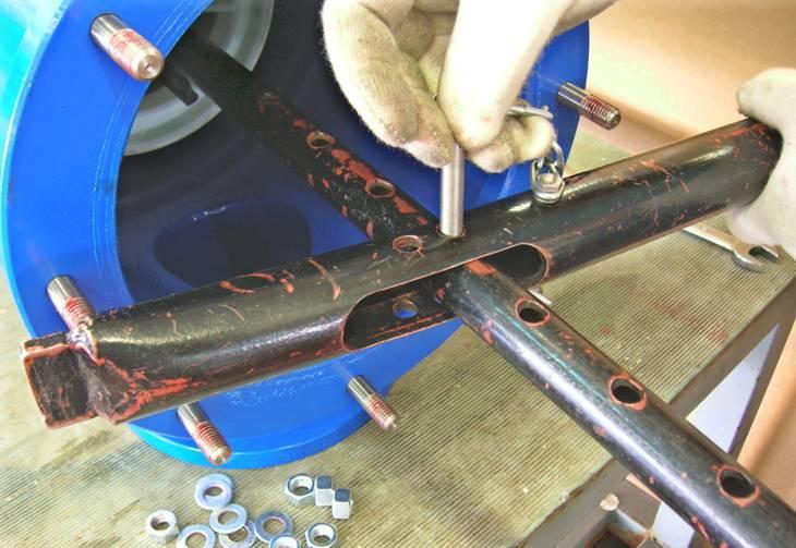
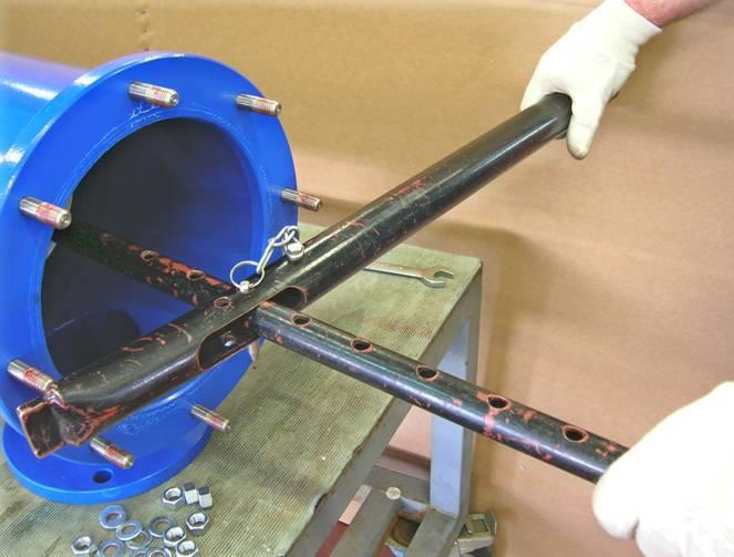
14 4. Pull the fine screen out of the filter housing. If it is difficult to release the screens use Amiad s Push Pull Tool (Catalog Number ) to extract the screen by performing the following procedure: A. Assemble the tool by inserting the fork shape part into the lever handle. B. Insert the fork shape part over the dirt collector shaft. C. Turn the tool clockwise till the fork teeth catch the fine screen handle. D. Lay the tip of the tool s lever handle on one of the filter s housing cover bolts (in order not to damage the filter paint coating) and secure the joint pin. E. Pull the handle firmly to release the screen. F. Pull the screen out of the filter housing. Joint Pin Lever Handle Fork Shape A Filtomat M Page 14 of 24


15 B C E D Filtomat M Page 15 of 24


16 F 5. Depending on the actual diameter of your filter use two units of Amiad s Screen Separation Tool (Catalog Number for 2-8, for or for filters) to separate the Chamber Flat Screen and the Dirt Collector from the Fine Screen. Filtomat M Page 16 of 24


17 Re-installing the Screen and the Dirt Collector 1. Insert the Dirt Collector to the Fine Screen. Make sure that the first suction nozzle of the Dirt Collector (A) is pointing downwards when inserted into the Fine Screen. A 2. Use the two Amiad s Screen Separation Tools to reconnect the Chamber Flat Screen and the Fine Screen. 3. Insert the fine screen back to the filter housing (A). Use the fork part of the Push Pull Tool to lift the screen and push it through the last few centimeters till it is correctly seated in the filter housing (B). A Filtomat M Page 17 of 24


18 B 4. Insert the Coarse Screen back to the filter housing (A), install the filter s cover (B) and retighten the cover bolts nuts (c). A B C Filtomat M Page 18 of 24
19 PARTS SCHEDULE No. Description Cat. No. 1 Filter housing 104XLP 15-14XX-XXXX 1 Filter housing 106XLP 15-16XX-XXXX 1 Filter housing 108LP 15-18XX-XXXX 1 Filter housing 110P X-XXXX 1.1 Plastic plug 1" Fitting 3/8" x Plastic plug 1/4" Way valve Nipple 1/4" X 1/8" Rinse controller /4" plastic filter Bracket Plastic plug 1/4" Stud bolt 1/2" X 50 (X16) Fine screen XLP XXXX 2 Fine screen 108LP/110P XXXX 2.1 O-Ring Handle bolt LP/XLP Handle bolt 108LP/110P Handle LP/XLP Handle 108LP/110P Spacer disc Fine screen bearing D. collector assembly O-Ring Rotor assembly Rotor DAG Rotor bearing housing Lower Bearing F. chamber flat screen F. chamber ZZ screen Dirt collector Bolt 3/8" X Dirt collector pipe Nozzle assembly DKF Collector connecting bolt Support bolt No. Description Cat. No Dirt collector shaft Dirt collector top plug Piston lid assembly (CI) Piston lid Plastic plug 1/4" L-Connector 1/4" X Piston shaft Exhaust valve seat DPF O-Ring P Rod DAF O-Ring P Exhaust valve seat O-Ring P Locking ring Disc seal seat DPF St.St. Nut 1/4" O-Ring P U-Ring 95X75X Seal holder U-Ring 95X75X St.St. Cylinder Piston rod tie O-Ring P Piston lid St.St. Lock nut 1/4" St.St. Washer M Plastic plug 1/4" Fitting 3/8" x Coarse screen 104XLP/106XLP Coarse screen 108LP/110P Filter lid O-Ring P Nut 1/2" (X 16) Washer 1/2" (X 16) Nipple 11/2" NPT Nipple 11/2" BSP Filtomat M Page 19 of 24
20 PARTS DRAWING #1 Filtomat M Page 20 of 24
21 PARTS DRAWING #2 Filtomat M Page 21 of 24
22 PARTS DRAWING #3 Filtomat M Page 22 of 24
23 PARTS DRAWING #4 Filtomat M Page 23 of 24
24 CONTROL DRAWING Filtomat M Page 24 of 24
Filtomat M100/MG Filters
 Filtomat M100/MG Filters Hydraulic self-cleaning screen filters, with no external power source required flow rates M100: up to 400 m 3 /h (1,760 gpm) MG: up to 800 m 3 /h (3,520 gpm) minimum operating
M300 Filters. Versatile and efficient self cleaning hydraulic filters that require no external power source
 M300 Filters Versatile and efficient self cleaning hydraulic filters that require no external power source flow rates filtration degrees water for cleaning minimum operating pressure up to 4840 US gpm
Operator's Manual. Models (¾") (1") (1½ ) (2 ) (3") (4") (6") (8")
 (1) (1½ ) (2 ) (3) (4) (6) (8)") OdisMatic Hydraulic Filter Series 851 Operator's Manual Models 85107 (¾") 85101 (1") 85115 (1½ ) 85102 (2 ) 85103 (3") 85104 (4") 85106 (6") 85108 (8") Content 1. Technical Specifications. 2. Materials.
OdisMatic Hydraulic Filter Series 851 Operator's Manual Models 85107 (¾") 85101 (1") 85115 (1½ ) 85102 (2 ) 85103 (3") 85104 (4") 85106 (6") 85108 (8") Content 1. Technical Specifications. 2. Materials.
To ensure proper installation, digital pictures with contact information to before startup.
 Check List for Optimal Filter Performance? There should be no back-pressure on the flush line. A 1 valve should have a 2 waste line, and 2 valve should have a 3 waste line. Do not use rubber hosing or
Check List for Optimal Filter Performance
 Check List for Optimal Filter Performance There should be no back-pressure on the flush line. A 1 valve should have a 2 waste line, and a 1.5" or 2 valve should have a 3 waste line. Do not use rubber hosing
Installation and Operation Instruction Manual FWINSMAN303. Yardney - Filtaworx FW06EX - FW10
 Installation and Operation Instruction Manual FWINSMAN303 Yardney - Filtaworx FW06EX - FW10 Phone: 951.656.6716 Toll-Free: 800.854.4788 www.yardneyfilters.com Yardney Water Management Systems, Inc. 6666
ARKAL SCREEN LINE H - SERIES Hydraulically Operated Self-Cleaning Screen Filter SERVICE & MAINTENANCE MANUAL
 ARKAL SCREEN LINE H - SERIES Hydraulically Operated Self-Cleaning Screen Filter SERVICE & MAINTENANCE MANUAL Table of Contents Subject Page No. Introduction... 2 Safety Instructions... 3 Description &
Installation & Operation Instruction Manual FWINSMAN300. Yardney - Filtaworx FW02 - FW03
 Installation & Operation Instruction Manual FWINSMAN300 Yardney - Filtaworx FW02 - FW03 Phone: 951.656.6716 Toll-Free: 800.854.4788 www.yardneyfilters.com Yardney Water Management Systems, Inc. 6666 Box
Tekleen LPF USERS AUTOMATIC FILTERS, INC. MANUAL
 AUTOMATIC FILTERS, INC. 2672 S. LA CIENEGA BLVD. LOS ANGELES, CA 90034 310 839 2828 800 336 1942 FAX 310 839 6878 www.tekleen.com info@tekleen.com Tekleen LPF USERS MANUAL Table of Contents SECTION I INTRODUCTION
Technical Specifications
 Technical Specifications Filter Type M100 750 M100 1500 M100 4500 M100 6800 General Data Maximum flow rate* 40 m³/h (175 US gpm) 80 m³/h (350 US gpm) 180 m³/h (793 US gpm) 400 m³/h (1760 US gpm) Inlet/Outlet
Filtomat M100/MG Filters
 Filtomat M100/MG Filters Hydraulic self-cleaning screen filters, with no external power source required flow rates M100: up to 400 m 3 /h (1,760 gpm) MG: up to 800 m 3 /h (3,520 gpm) minimum operating
Filtomat M100/MG Filters
 Filtomat M100/MG Filters Hydraulic self-cleaning screen filters, with no external power source required flow rates minimum operating pressure water for cleaning filtration degrees M100: up to 1,760 gpm
GL Ludemann Y-Strainers
 GL Ludemann Y-Strainers Installation, Operation and Maintenance Manual English Issue 1-03/2014 - Page 1/7 GENERAL These instructions are for installing, operation and maintenance of Y-strainers fabricated
M100 Filters. The most efficient hydraulic filters that require no external power source micron less than 1% of the total flow.
 M100 Filters The most efficient hydraulic filters that require no external power source flow rates filtration degrees water for cleaning minimum operating pressure up to 400 m 3 /h (1760 US gpm) 500-80
Spin Klin 12" Super Flow
 Spin Klin 12" Super Flow w w w. a r k a l - f i l t e r s. c o m Galaxy Super Flow Spin Klin Battery Standard Automatic Backwash Operation and Maintenance Manual Filtration Process During filtration, water
Spin Klin 3"-4" Apollo Angle
 Spin Klin 3"-4" Apollo Angle w w w. a r k a l - f i l t e r s. c o m 3"-4" Spin Klin Angle Apollo Battery Service & Maintenance Manual Table of Contents Subject Page No. 1. Introduction... 3 2. Safety
AMIAD "TAF" FILTER SERIES
 AMIAD "TAF" FILTER SERIES 2" - 3" Automatic electric filters for flow rates up to 50 m 3 /h; 220 USgpm An innovative self-cleaning filter, constructed of high quality plastic; suitable for a large variety
AMIAD Automatic Filters
 1. Model EBS AMIAD Automatic Filters Maintenance Guidelines General inspection In order to check the proper operation of the filter, close the low-pressure 1/4" valve to the pressure differential switch
Filtomat M100/MG Filters
 Filtomat M100/MG Filters Hydraulic self-cleaning screen filters, with no external power source required flow rates minimum operating pressure water for cleaning filtration degrees M100: up to 1,760 gpm
M100 Filters. The most efficient hydraulic filters that require no external power source micron less than 1% of the total flow.
 M100 Filters The most efficient hydraulic filters that require no external power source flowrates filtration degrees water for cleaning minimum operating pressure up to 400 m 3 /h (1760 US gpm) 500-80
Pressure Reducing Valve Type 2114/2415
 Pressure Reducing Valve Type 2114/2415 Fig. 1 Type 2114/2415 1. Design and principle of operation The Type 2114/2415 Pressure Reducing Valve consists of the Type 2114 Valve and the Type 2415 Actuator.
4" Spin Klin Twin Apollo Battery. Service & Maintenance Manual
 4" Spin Klin Twin Apollo Battery Service & Maintenance Manual Table of Contents Subject Page No. 1. Introduction... 3 2. Safety Instructions... 3 3. Description and Operation... 4 4. Technical Data...
Spin Klin 4" Apollo Twin
 Spin Klin 4" Apollo Twin w w w. a r k a l - f i l t e r s. c o m 4" Spin Klin Twin Apollo Battery Service & Maintenance Manual Table of Contents Subject Page No. 1. Introduction... 3 2. Safety Instructions...
Crispin Valves Operating Guide. Crispin
 Crispin Valves Operating Guide Crispin Since 1905 Crispin Multiplex Manufacturing Co. 600 Fowler Avenue Berwick, PA 18603 1-800-AIR-VALV T: (570) 752-4524 F: (570) 752-4962 www.crispinvalve.com sales@crispinvalve.com
CUSTOM COMBINATION AIR VALVE
 INSTALLATION / OPERATION / MAINTENANCE CUSTOM COMBINATION AIR VALVE INTRODUCTION This manual will provide you with the information to properly install and maintain this valve to ensure a long service life.
Mustang Series PRESSURE REDUCING CONTROL VALVE. M115 (Globe) M1115 (Angle) Schematic. Standard Components. Options & Accessories.
 M1115 (Angle) Schematic. Standard Components. Options & Accessories.") PRESSURE REDUCING CONTROL VALVE 02/09 Schematic Throttles to reduce high upstream pressure to constant lower downstream pressure Reducing setpoint is adjustable 2 (AOS) P/L Standard Components 1 Main Valve
PRESSURE REDUCING CONTROL VALVE 02/09 Schematic Throttles to reduce high upstream pressure to constant lower downstream pressure Reducing setpoint is adjustable 2 (AOS) P/L Standard Components 1 Main Valve
Operation and Maintenance of Mechanical Self-Cleaning Filters. Maynard King CB Tubecraft div of K&D Pratt
 Operation and Maintenance of Mechanical Self-Cleaning Filters Maynard King CB Tubecraft div of K&D Pratt Filtration Terms Filter Area The total area of a filter element, usually expressed in square inches
Operating manual Separator
 Operating manual Separator Sheet no. AS/4.1.141.1.1 issue 20.08.2014 Contents Section Title Page 0 Introduction... 1 1 Intended use......1 2 Marking of the fitting... 1 3 Safety instructions... 2 4 Transport
Type 644 and 645 Differential Pressure Pump Governors
 Instruction Manual 644 and 645 Pump Governors Type 644 and 645 Differential Pressure Pump Governors Introduction Scope of Manual This instruction manual provides information on installation, adjustment,
DP556 Pump. 55:1, Air-operated, Grease. General. Operation. Technical Data. Installation. Mounting with Reinforced Cover (Recommended)
") DP556 Pump 55:1, Air-operated, Grease General The DP556 Pump is a compressed air-operated reciprocating piston pump. This high capacity demand pump is compatible with mineral and synthetic grease and suitable
DP556 Pump 55:1, Air-operated, Grease General The DP556 Pump is a compressed air-operated reciprocating piston pump. This high capacity demand pump is compatible with mineral and synthetic grease and suitable
PRESSURE REDUCING VALVE
 Schematic Throttles to reduce high upstream pressure to constant lower downstream pressure Low Flow By-Pass controls at low flows 4 PRESSURE REDUCING VALVE with LOW-FLOW BY-PASS FEATURE Main Line valve
PRESSURE REDUCING VALVE
 Schematic Throttles to reduce high upstream pressure to constant lower downstream pressure Low Flow By-Pass controls at low flows 4 PRESSURE REDUCING VALVE with LOW-FLOW BY-PASS FEATURE Main Line valve
DP3 Pump. 3:1, Air-operated, Oil. General. Operation. Technical Data. Installation R0 10/09. 35a 35b 35c
 DP3 Pump 3:1, Air-operated, Oil General The DP3 Pump is a compressed air-operated piston reciprocating medium pressure pump. Suitable for medium flow transfer of high viscosity lubricants and for oil delivery
Mounting and Operating Instructions EB 8135/8136 EN. Series V2001 Valves Type 3535 Three-way Valve for Heat Transfer Oil
 Series V2001 Valves Type 3535 Three-way Valve for Heat Transfer Oil Type 3535 Three-way Valve with bellows seal and rod-type yoke (partial view) Mounting and Operating Instructions EB 8135/8136 EN Edition
PRESSURE REDUCING CONTROL VALVE
 PRESSURE REDUCING CONTROL VALVE 06/08 Schematics Throttles to reduce high upstream pressure to constant lower downstream pressure Reducing setpoint is adjustable 2 (AOS) X P/L Standard Components 1 Main
AMIAD "ABF-L" FILTER SERIES
 AMIAD "ABF-L" FILTER SERIES 8" - 14" Automatic Brush Filters for flow rates up to 1000 m 3 /h (4400 USgpm) Two models available: ABF-6,000 and ABF-10,000 Reduce maintenance costs on down stream equipment.
AMIAD "HydroTAF" FILTER SERIES
 AMIAD "HydroTAF" FILTER SERIES 2"/3" Hydraulic automatic filters for flow rates up to 50 m 3 /h (220 USgpm) This compact self-cleaning filter operates on water pressure and does not need any external source
Val-Matic 1-4 Combination Air Valve (Single Housing Type)
") Manual No. ARCO-OM1-3 Val-Matic 1-4 Combination Air Valve (Single Housing Type) Operation, Maintenance and Installation Manual INTRODUCTION... 1 RECEIVING AND STORAGE... 1 DESCRIPTION OF OPERATION... 1
Manual No. ARCO-OM1-3 Val-Matic 1-4 Combination Air Valve (Single Housing Type) Operation, Maintenance and Installation Manual INTRODUCTION... 1 RECEIVING AND STORAGE... 1 DESCRIPTION OF OPERATION... 1
FILTRATION AMIAD PLASTIC FILTERS, SCREENS & DISCS
 AMIAD PLASTIC FILTERS, SCREENS & DISCS Max pressure 10 bar, max temperature 60 O 3/4 to 1 1/2 bodies manufactured from poly acetal 2 bodies and above manufactured from poly made and glass fibre 3/4 to
SEMI-AUTOMATIC Filters. Quick and efficient way for cleaning manual filters
 irrigationglobal.com filtration for irrigation systems SEMI-AUTOMATIC Filters filtration degrees scanaway filtration degrees brushaway supported diameters max. operating pressure 500-50 micron 3500-200
OPERATION MANUAL AIR-OPERATED DOUBLE DIAPHRAGM PUMPS 3 POLYPROPYLENE PUMP PWR-FLO TM AIR DISTRIBUTION SYSTEM NPF 80. A JDA Global Company
 OPERATION MANUAL 3 POLYPROPYLENE PUMP PWR-FLO TM AIR DISTRIBUTION SYSTEM NPF 80 AIR-OPERATED DOUBLE DIAPHRAGM PUMPS A JDA Global Company CAUTIONS - READ FIRST CAUTION: Do not apply compressed air to the
Fisher 644 and 645 Differential Pressure Pump Governors
 Instruction Manual 644 and 645 Pump Governors Fisher 644 and 645 Differential Pressure Pump Governors Contents Introduction... 1 Scope of Manual... 1 Description... 1 Specifications... 2 Educational Services...
KEYSTONE SERIES 320 BUTTERFLY VALVES INSTALLATION AND MAINTENANCE INSTRUCTIONS
 Before installation these instructions must be fully read and understood HAZARD POTENTIALS disregarding of instructions improper use of product insufficiently qualified personnel Valve application to be
PRESSURE REDUCING VALVE
 Schematic Throttles to reduce high upstream pressure to constant lower downstream pressure Closes quickly when downstream pressure exceeds reduced pressure setpoint 3 PRESSURE REDUCING VALVE with SURGE
Butterfly valves Figure 56 Installation & Maintenance Instructions
 KEYSTONE Please read these instructions carefully This symbol indicates important messages and safety instructions. Hazard potentials: disregarding of instructions improper use of product insufficiently
PARTS SPECIFICATIONS
 CHECK VALVES MODELS NR- 010, NR-020 a. Model NR- 010 B NO PART PARTS SPECIFICATIONS MATERIAL BODY REINFORCED NYLON DISC REINFORCED NYLON SEAL RUBBER EPDM BOLT STAINLESS STEEL 316 SHAFT STAINLESS STEEL
APCO CRF-100A RUBBER FLAPPER SWING CHECK VALVES
 APCO CRF-100A RUBBER FLAPPER SWING CHECK VALVES Instruction D12043 June 2016 DeZURIK Instructions These instructions provide installation, operation and maintenance information for APCO CRF-100A Rubber
MAP Automatic Strainers In-Line Series
 MAP Automatic Strainers In-Line Series flow rate filtration degrees inlet / outlet diameters min. operating pressure up to 4.500 m 3 /h (19.800 gpm) 5.000 200 micron up to DN800 (32 ) 1 bar (15 psi) Heavy
Val-Matic 1-4 Combination Air Valve (Single Housing Type)
") Manual No. ARCO-OM1-2 Val-Matic 1-4 Combination Air Valve (Single Housing Type) Operation, Maintenance and Installation Manual INTRODUCTION... 1 RECEIVING AND STORAGE... 1 DESCRIPTION OF OPERATION... 1
Manual No. ARCO-OM1-2 Val-Matic 1-4 Combination Air Valve (Single Housing Type) Operation, Maintenance and Installation Manual INTRODUCTION... 1 RECEIVING AND STORAGE... 1 DESCRIPTION OF OPERATION... 1
MODEL 200 MULTI-JET FLOW METER
 MODEL 200 MULTI-JET FLOW METER - For Water Applications - INSTALLATION & INSTRUCTION MANUAL 8635 Washington Avenue Racine, Wisconsin 53406 Toll Free: 800.235.1638 Phone: 262.639.6770 Fax: 262.417.1155
MODEL 900 IMPELLER-TYPE FLOW METER
 MODEL 900 IMPELLER-TYPE FLOW METER - For Water Applications - INSTALLATION & INSTRUCTION MANUAL 8635 Washington Avenue Racine, Wisconsin 53406 Toll Free: 800.235.1638 Phone: 262.639.6770 Fax: 262.417.1155
INSTALLATION/OPERATION/MAINTENANCE INSTRUCTIONS FOR ARCHON MODELS WD2010L, WD2010, WD2010H WASHDOWN STATIONS. ARCHON Industries, Inc.
 ARCHON Industries, Inc. Washdown Stations Models WD2010L, WD2010, WD2010H Installation / Operation / Maintenance Instructions 1 This manual has been prepared as an aid and guide for personnel involved
OPERATION MANUAL.25 METALLIC PUMP PWR-FLO TM AIR DISTRIBUTION SYSTEM
 OPERATION MANUAL.25 METALLIC PUMP PWR-FLO TM AIR DISTRIBUTION SYSTEM CAUTIONS - READ FIRST CAUTION: Do not apply compressed air to the exhaust port pump will not function. CAUTION: Do not exceed 79 C (174
Tekleen ABW USERS AUTOMATIC FILTERS, INC. MANUAL
 AUTOMATIC FILTERS, INC. 2672 S. LA CIENEGA BLVD. LOS ANGELES, CA 90034 310 839 2828 800 336 1942 FAX 310 839 6878 www.tekleen.com info@tekleen.com Tekleen ABW USERS MANUAL ABW USERS MANUAL AUTOMATIC FILTERS,
WARNING Carefully Read These Instructions Before Use
 DO NOT RETURN THIS SPRAYER TO STORE Call: 1-800-950-4458 Backpack Sprayer Use and Care Manual Manufactured for Northern Tool + Equipment Co., Inc. WARNING Carefully Read These Instructions Before Use Model
Operating Instructions
 Operating Instructions Quadax Series Butterfly Valves (with actuator) Version September 2009 müller co-ax ag Gottfried-Müller-Str. 1 74670 Forchtenberg Germany Tel. +49 7947 828-0 Fax +49 7947 828-11 E-Mail
LEAD FREE * LFM115 (Globe) LFM1115 (Angle)
 LFM1115 (Angle)") ES-ACV-SB-LFM115_LFM1115 LEAD FREE * Pressure Reducing Control Valve Schematic Throttles to reduce high upstream pressure to constant lower downstream pressure Reducing setpoint is adjustable 2 (AOS) P/L
ES-ACV-SB-LFM115_LFM1115 LEAD FREE * Pressure Reducing Control Valve Schematic Throttles to reduce high upstream pressure to constant lower downstream pressure Reducing setpoint is adjustable 2 (AOS) P/L
APCO ASR-400/450 SEWAGE AIR RELEASE VALVES
 APCO ASR-400/450 SEWAGE AIR RELEASE VALVES Instruction D12005 December 2012 Instructions These instructions provide installation, operation and maintenance information for the APCO ASR- 400/450 Sewage
LEAD FREE * LFF115 (Globe) LFF1115 (Angle)
 LFF1115 (Angle)") ES-ACV-SB-LFF115_LFF1115 LEAD FREE * Pressure Reducing Control Valve Schematics Throttles to reduce high upstream pressure to constant lower downstream pressure Reducing setpoint is adjustable 2 (AOS)
ES-ACV-SB-LFF115_LFF1115 LEAD FREE * Pressure Reducing Control Valve Schematics Throttles to reduce high upstream pressure to constant lower downstream pressure Reducing setpoint is adjustable 2 (AOS)
CONTENTS. VIKING PUMP, INC. A Unit of IDEX Corporation Cedar Falls, IA USA SECTION TSM 710.1
 TECHNICAL SERVICE MANUAL industrial heavy duty motor speed pumps SERIES 4076 AND 4176 SIZES hle, ate and ale SECTION TSM 710.1 PAGE 1 of 8 ISSUE B CONTENTS Introduction....................... 1 Safety
Instructions Parts List
 Instructions Parts List : RATIO Fast Flo Pump Air operated piston transfer pump for low viscosity fluids. For professional use only. Only models that are EX certified are approved for use in European explosive
Installation and Operating Instructions
 Original Installation and Operating Instructions Hawle E2 Valve with Flange Outlet, System 2000 or PE Spigot Ends Table of Contents A) General...... 2 A1 Symbols..... 2 A2 Intended use... 2 A3 Labeling...
Bray/ VAAS Slurry Series Knife Gate Valve 760/762/765/766/767/768 Series Operation and Maintenance Manual
 Bray/ VAAS Knife Gate Valve 760/762/765/766/767/768 Series Table of Contents Definition of Terms 1 Safety Instructions 1 Introduction 2 Unpacking 2 Storage 2 Installation 3 Commissioning 3 Cylinder-Operated
SPIN KLIN GALAXY. Service & Maintenance Manual
 SPIN KLIN GALAXY Service & Maintenance Manual Mode of Operation Filtration Process During the filtration process the water flows through the inlet manifold, reaching the 4 filters through the 4 x3 inlet
HARMSCO Hurricane Swing Bolt Water Filters Models: HUR 1X170FL, HUR 3X170FL HUR 5X170FL, & HUR 8X170FL
 Models: HUR 1X170FL, HUR 3X170FL HUR 5X170FL, & HUR 8X170FL INSTALLATION AND OPERATION MANUAL HUR 8X170FL HUR 5X170FL HUR 3X170FL HUR 1X170FL Harmsco Filtration Products With Patented Up-Flow and Tangential/Rotational
Diaphragm Valves Type 15
 Serial No. H-V031-E-8 Diaphragm Valves Type 15 User s Manual Contents (1) Be sure to read the following warranty clauses of our product 1 (2) General operating instructions 2 (3) General instructions for
EP1306N 5 Gallon Can Extruder System Rev. A June EP1306N Operation Manual
 EP1306N Operation Manual 1 THIS PAGE HAS BEEN INTENTIONALLY LEFT BLANK 2 TABLE OF CONTENTS SECTION 1: SAFETY... 4 1. GENERAL SAFETY... 5 2. PUMP SAFETY... 5 3. FLUID PRESSURE AND COMPATIBILITY... 6 4.
Ph: (07) Fax: (07) Pump Manual
 Fax: (07) Pump Manual") sales@scintex.com.au www.scintex.com.au Ph: (07) 3137 0135 Fax: (07) 3041 0541 Pump Manual 12V 75LPM Vane Pump & Vane Pump Station SPEP12V75 & SP12VFS75 SPEP12V75 SP12VFS75 Parts List No. Part Name QTY
sales@scintex.com.au www.scintex.com.au Ph: (07) 3137 0135 Fax: (07) 3041 0541 Pump Manual 12V 75LPM Vane Pump & Vane Pump Station SPEP12V75 & SP12VFS75 SPEP12V75 SP12VFS75 Parts List No. Part Name QTY
Mounting and Operating Instructions EB 5894 EN. Electric control valves with jet pump. Flanged version of valve with jet pump
 Electric control valves with jet pump Type 3267/5824, Type 3267/5825, Type 3267/3374, Type 3267/3274 Pneumatic control valves with jet pump Type 3267-1, Type 3267-7 Flanged version of valve with jet pump
Fast-Flo Pump INSTRUCTIONS-PARTS LIST. Table of Contents 1:1 RATIO
 INSTRUCTIONS-PARTS LIST INSTRUCTIONS This manual contains important warnings and information. READ AND KEEP FOR REFERENCE. First choice when quality counts. 07 7 Rev. Z Supersedes W Includes Rev. Y changes
PRODUCT OPERATING MANUAL
 PRODUCT OPERATING MANUAL PANBLAST TM BP600 3 BLAST POT Manual Number: ZVP PC 0154 00 SECTION 1. GENERAL INFORMATION 2. INITIAL SETUP INSTRUCTIONS 3. OPERATING INSTRUCTIONS 4. MAINTENANCE 5. TROUBLE SHOOTING
INSTALLATION, OPERATION, AND MAINTENANCE MANUAL
 INSTALLATION, OPERATION, AND MAINTENANCE MANUAL MODEL 4D-200 REDUCED PRESSURE PRINCIPLE (RPZ) & MODEL 4D-700 REDUCED PRESSURE DETECTOR ASSEMBLY (RPDA) BACKFLOW PREVENTERS 2 ½ 10 Conbraco Industries Inc.
MODEL 1100 TURBINE FLOW METER
 MODEL 1100 TURBINE FLOW METER INSTALLATION & INSTRUCTION MANUAL 8635 Washington Ave. Racine, Wisconsin 53406 Phone: 800.433.5263 Fax: 800.245.3569 www.hedland.com 2 OPERATIONAL START-UP Fluid entering
MODEL 200 MULTI-JET FLOW METER
 MODEL 200 MULTI-JET FLOW METER - For Water Applications - INSTALLATION & INSTRUCTION MANUAL 8635 Washington Avenue Racine, Wisconsin 53406 Technical Toll-Free: 877.722.4631 Sales Toll-Free: 800.235.1638
Steam/Water Washdown Units Safety and Operation Installation and Maintenance Instructions
 INSTALLATION AND MAINTENANCE INSTRUCTIONS IM-8-002-US October 2016 Steam/Water Washdown Units Safety and Operation Installation and Maintenance Instructions These instructions should be read by the Company
FLUXA EBS FILTER SERIES. The largest automatic self-cleaning filter for fine filtration. For flow rates up to 4000 m 3 /h
 EBS FILTER SERIES Leaflet F-09-02-UK FLUXA Fluxa Filtri S.p.A. V.le A. De Gasperi, 88/B-20017 Mazzo di Rho (MI) Tel. 0293959.1 (15 lines) Fax 0293959.400-440-470 e-mail: info@fluxafiltri.com - www.fluxafiltri.com
DP5 Pump. 5:1, Air-operated, Heavy Duty, Oil. General. Operation. Technical Data. Installation R1 09/10
 DP5 Pump 5:1, Air-operated, Heavy Duty, Oil General The DP5 Pump is a compressed air-operated reciprocating piston medium pressure pump. These pumps are suitable for distribution of all types of light
TABLE OF CONTENT. 7-Operating mechanisms of Non-return valve with hydraulic damping cylinder
 TABLE OF CONTENT Title 1- Tilting-Disc Non-Return valves with counter weight (NVTW) 2-Parts list 3-Installation Non-return valve and Butterfly Valve 4-Dimensions 5-Installation of Non-return valves with
OPERATING AND MAINTENANCE MANUAL BATCH PRESSURE FILTER 3 GALLON CAPACITY
 OPERATING AND MAINTENANCE MANUAL BATCH PRESSURE FILTER 3 GALLON CAPACITY SEPOR, INC 718 N FRIES AVE. WILMINGTON, CA 90744 310 830 6601 Fax: 310 830 9336 info@sepor.com Installation The 3 gallon batch pressure
90 SERIES SELF CLEANING WATER FILTER OPERATION & MAINTENANCE MANUAL
 90 SERIES SEF CEANING WATER FITER OPERATION & MAINTENANCE MANUA CONTENTS Filter Basics Installation Requirements Flush ine Hydraulic Connections Hydraulic Piston Filter Performance Normal Operation Backwash
Mounting and Operating Instructions EB 5863 EN. Electric Control Valves. Pneumatic Control Valve
 Electric Control Valves Types 3226/5857, 3226/5824, 3226/5825, 3226/5757-7, 3226/5724-8, 3226/5725-7, 3226/5725-8 Pneumatic Control Valve Type 3226/2780 Type 3226/5857 Type 3226/5757-7 Type 3226/2780-2,
OPERATION MANUAL. ALUMINUM Models DUCTILE Models 316 S.S. Models AIR-OPERATED DOUBLE DIAPHRAGM PUMPS
 OPERATION MANUAL 2 METALLIC PUMP (CLAMPED) PWR-FLO TM AIR DISTRIBUTION SYSTEM NPF50 AIR-OPERATED DOUBLE DIAPHRAGM PUMPS ALUMINUM Models DUCTILE Models 316 S.S. Models A JDA Global Company CAUTIONS - READ
I & M 8000 Series. Ideal Installation Schematic. Preferred Installation. Trouble Shooting
 I & M 8000 Series 3170 Wasson Road Cincinnati, OH 45209 USA Phone 513-533-5600 Fax 513-871-0105 lowflow@richardsind.com www.lowflowvalve.com Installation & Maintenance Instructions for 8000 Series Low
Parker Hannifin Filtration Group Racor Division DUAL FBO OPERATION AND MAINTENANCE INSTRUCTIONS SPARE PARTS
 Parker Hannifin Filtration Group OPERATION AND MAINTENANCE INSTRUCTIONS SPARE PARTS DFBO-10-IN/DFBO-14-IN DFBO-14-MA 2(23) Duplex Fuel Filter / Separator Operation and Maintenance Instructions 73309 031912
NEOTECHA NTB-NTC BALL VALVES INSTALLATION AND MAINTENANCE INSTRUCTIONS
 Before installation these instructions must be fully read and understood 2 SAFETY Please also read through these notes carefully. 2.1 General potential danger due to: a. Failure to observe the instructions
These installation and maintenance instructions must be read in full and completely understood before the installation!
 These installation and maintenance instructions must be read in full and completely understood before the installation! 1. General information on the installation and maintenance instructions These instructions
DIFFERENTIAL PRESSURE RELIEF REGULATOR TYPE A4AL Port Size 3/4"- 4" (20-100mm) For Ammonia, R-22, R134a, R404a, R507 and other common refrigerants.
 For Ammonia, R-22, R134a, R404a, R507 and other common refrigerants.") DIFFERENTIAL PRESSURE RELIEF REGULATOR TYPE A4AL Port Size 3/4"- 4" (20-100mm) For Ammonia, R-22, R134a, R404a, R507 and other common refrigerants. FEATURES Pilot operated characterized Modulating Plug
DIFFERENTIAL PRESSURE RELIEF REGULATOR TYPE A4AL Port Size 3/4"- 4" (20-100mm) For Ammonia, R-22, R134a, R404a, R507 and other common refrigerants. FEATURES Pilot operated characterized Modulating Plug
1/2" AIR DRIVEN DIAPHRAGM PUMP
 1/2" DRIVEN DIAPHRAGM PUMP OPERATION AND SERVICE GUIDE O-1225D NOV. 2008 Page 1 of 6 Refer to Bulletin P-605, Parts List P-9151 DRIVEN, DOUBLE DIAPHRAGM PUMP MANUAL Congratulations on purchasing one of
Mounting and Operating Instructions EB 8222 EN. Type 3310/AT and Type 3310/3278 Pneumatic Control Valves. Type 3310 Segmented Ball Valve
 Type 3310/AT and Type 3310/3278 Pneumatic Control Valves Type 3310 Segmented Ball Valve Fig. 1 Type 3310/3278 with positioner Fig. 2 Type 3310/AT Mounting and Operating Instructions EB 8222 EN Edition
Owner's Manual. Model: LS-PCO-100-GEM ( ) (100 Gallon Skid-Mounted High Pressure Sprayer) Technical Specifications. General Information
 (100 Gallon Skid-Mounted High Pressure Sprayer) Technical Specifications. General Information") Owner's Manual Model: LS-PCO-00-GEM (5302043) (00 Gallon Skid-Mounted High Pressure Sprayer) Technical Specifications 00 Gallon Corrosion-Resistant PCO Tank 5.5 HP Honda Engine 990-D403GRGI Pump: (Maximun
Owner's Manual Model: LS-PCO-00-GEM (5302043) (00 Gallon Skid-Mounted High Pressure Sprayer) Technical Specifications 00 Gallon Corrosion-Resistant PCO Tank 5.5 HP Honda Engine 990-D403GRGI Pump: (Maximun
Bell AF200 Series Hydraulic Self-Cleaning Screen Filter
 v# 07-2018 Bell AF200 Series Hydraulic Self-Cleaning Screen Filter SERVICE & MAINTENANCE MANUAL E.L.I. Filtering LTD. Sha ar Efraim 42835 Israel. Tel: +972-4-6220006 Fax: +972-4-6220042 e-mail: yamit@yamit-f.com
LABORATORY ZERO AIR GENERATOR MODEL N-GC1500 USER S MANUAL
 LABORATORY ZERO AIR GENERATOR MODEL N-GC1500 USER S MANUAL Content 1. Introduction...2 2. Important safety instruction...3 3. System component...4 4. Engineering design overview...5 5. Installation...6
Wastewater Air Release Valve Models 48A, 49A
 Manual No. WWAR-OM1-2 Wastewater Air Release Valve Models 48A, 49A Operation, Maintenance and Installation Manual INTRODUCTION... 1 RECEIVING AND STORAGE... 1 DESCRIPTION OF OPERATION... 1 INSTALLATION...
DP33 Pump. 60:1, 3+3, Air-operated, Grease. General. Operation. Technical Data. Installation R2 08/15
 DP33 Pump 0:1, 3+3, Air-operated, Grease General The DP33 Pump is a compressed air-operated reciprocating piston pump designed to pump all types of mineral greases. Suitable for installations with medium
TYPE E Main Valve Sizes 3 /8 through 12
 Technical Data SD 3001E PRINTED IN U.S.A. SD 3001E/9709 SPENCE ENGINEERING COMPANY, INC. 150 COLDENHAM ROAD, WALDEN, NY 12586-2035 A B TYPE E MAIN VALVE FACE TO FACE DIMENSIONS C D E DIMENSIONS (inches)
SAFETY MANUAL READ FIRST!
 966-05-XX SAFETY MANUAL READ FIRST! IMPORTANT: READ THESE WARNINGS AND SAFETY PRECAUTIONS PRIOR TO INSTALLATION OR OPER- ATION. FAILURE TO COMPLY WITH THESE INSTRUC- TIONS COULD RESULT IN PERSONAL INJURY
3 Spin Klin Battery Operation and Maintenance Manual
 3 Spin Klin Battery Operation and Maintenance Manual Operation During the filtration stage, water flows through the INLET manifold and is distributed through the 3 x 2 backwash valves into the S.K. filters.
2311FA. Pressure Tester USER INSTRUCTION MANUAL BARFIELD M/N 2311FA Revision C April 12, 2011 BARFIELD, INC. Corporate Headquarters
 2311FA Pressure Tester USER INSTRUCTION MANUAL BARFIELD M/N 2311FA 56-101-00212 Revision C April 12, 2011 BARFIELD, INC. Corporate Headquarters 4101 Northwest 29th Street Miami, Florida 33142 www.barfieldinc.com
VSI, LLC SERIES 2100 RESILIENT SEATED BUTTERFLY VALVES INSTALLATION, OPERATION AND MAINTENANCE MANUAL
 VSI SERIES 2100 RESILIENT SEATED BUTTERFLY VALVES VSI, LLC. 2-0 SERIES 2100 RESILIENT SEATED BUTTERFLY VALVES INSTALLATION, OPERATION AND MAINTENANCE MANUAL Publication: V2100- August 2016 TABLE OF CONTENTS
Operation Manual BOTTLE TOP DISPENSER
 Operation Manual BOTTLE TOP DISPENSER TABLE OF CONTENTS Page No. Intended Use Of The Instrument 1 Safety Instructions 1 Functions and Limitations of Use 2 Operating Exclusions 3 Storage Conditions 3 Chemical