OEM INSTALLATION MANUAL
|
|
|
- Hugo Ellis
- 6 years ago
- Views:
Transcription


1 G C P 6 P OEM INSTLLTION MNUL Rev: Page 1 Ground Control 3.0 OEM Installation Manual
2 System and Safety Information TLE OF CONTENTS System and Safety Information 2 Preparation 2 Criteria for Determining Use of Ground Control Point or 6-Point System 3 4-Point pplication 3 6-Point pplication 3 Installation - Rear Jacks 4 Installation - Rear Sensor 4 Installation - Controller 7 Installation - Touch Pad 8 Wiring Diagram - 4 Point 9 Wiring Diagram - 6 Point 10 Touch Pad Diagram 11 operation 12 asic Jack Operation 12 Homing Jacks 12 Zero Point Calibration 13 Special Jack Error Codes 13 Touch Pad Error Codes 14 Failure to act in accordance with the following may result in death or serious personal injury. The use of the Ground Control 3.0 leveling system to support the unit for any reason other than which it is intended is prohibited by Lippert s limited warranty. The Lippert leveling system is designed as a leveling system only and should not be used to provide service for any reason under the coach such as changing tires or servicing the leveling system. ny attempts to change tires or perform other service while unit is supported by the Ground Control 3.0 leveling system could result in damage to the 5th wheel and/or cause death or serious injury. e sure to park the unit on solid, level ground. Clear all jack landing locations of debris and obstructions. Locations should also be free of depressions. When parking the unit on extremely soft surfaces, utilize load distribution pads under each jack. People and pets should be clear of coach while operating leveling system. Never lift the unit completely off the ground. Lifting the unit so the wheels are not touching the ground will create an unstable and unsafe condition. Preparation 1. nalyze the unit. Determine where the rear jack brackets, controller, and touch pad will be mounted on the unit. The rear jack brackets should be mounted approximately 1 foot behind the rear axle hanger and be aligned with each other. Jack brackets may already be pre-installed by LCI. The controller should be mounted in the center of the unit in compliance with RVI Gas Codes as the controller connections are not spark-proof. The touch pad should be mounted in a compartment on the side of the unit so that the operator will have a view of the hitch pin while using the touch pad. The touch pad MUST also be protected from the elements. NoTE: The landing gear will be installed to the frame of the unit by LCI. Rev: Page 2 Ground Control 3.0 OEM Installation Manual
. Fig.")
. Fig.")
3 Criteria for Determining Use of Ground Control Point or 6-Point System 4-Point pplication If the GVWR of the unit is less than 15,000 lbs. ND the distance between the center of the landing gear foot and the center of the rear jack foot will be less than 20 feet (Fig. 1). Fig. 1 < 20' 6-Point pplication If the GVWR of the unit is 15,000 lbs. or more OR the distance between the center of the landing gear foot and the center of the rear jack foot will be 20 feet or greater (Fig. 2). Fig. 2 > 20' NoTE: If either the GVWR is greater than 15,000 lbs. or the distance on center between the landing gear jack foot and the rear jack foot is 20 feet or greater, the 6-point Ground Control System MUST be installed. Rev: Page 3 Ground Control 3.0 OEM Installation Manual

 should be mounted approximately 1 foot behind the")


.")

 using six bolts (Fig. 3E) and nuts (Fig. 3) per jack.")


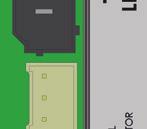
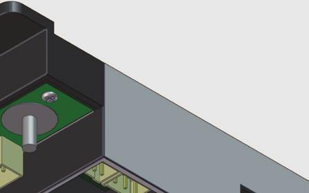
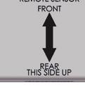
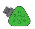
4 Installation - Rear Jacks 1. Determine position and ground clearance requirements for the rear jacks (Fig. 3D). The rear jack brackets (Fig. 3C) should be mounted approximately 1 foot behind the rear axle hanger and be aligned with each other. NoTE: When fully retracted, rear jacks should be equal to the departure angle or a minimum of 7" of ground clearance. 2. Mark jack mounting bracket (Fig. 3C) locations on the main frame rail. 3. Clamp the bracket to the main frame rail (Fig. 3) in the marked position. 4. Weld the bracket to the main frame rail (Fig. 3). Jack brackets may already be pre-installed by LCI. 5. olt the rear jacks (Fig. 3D) to the mounting brackets (Fig. 3C) using six bolts (Fig. 3E) and nuts (Fig. 3) per jack. Tighten the bolts to 90 lb.-ft. of torque. 6. Connect the wire harnesses to the rear jack motor wires and run the harnesses to the compartment where the controller will be mounted. NoTE: LCI recommends zip-tying the harnesses tight against the rear jack motors to prevent damage to the harnesses. Fig. 3 Weld C D E Installation - Rear Sensor The rear sensor (Fig. 4) MUST be installed on the crossmember to the rear of the back axle, centered curbside to roadside on the unit with the arrows on the top of the sensor pointing the correct direction (Fig. 4 detail). Fig. 4 Fig. 4 Detail Rev: Page 4 Ground Control 3.0 OEM Installation Manual


 to")
 using two 3")


5 1. Dry fit the mounting plate (Fig. 5) and the rear sensor (Fig. 5) to the crossmember (Fig. 5C). The predrilled holes in the plate are for mounting the rear sensor to the plate. Mark on the plate where the rear sensor will set. Space between the sensor and the crossmember MUST be left so the wire harness will not be pinched. Fig. 5 C Front Rear 2. ttach the rear sensor (Fig. 6) to the mounting plate (Fig. 6C) using two 3 8" hex head self-tapping screws (Fig. 6). Orientation is imperative for the correct operation of the leveling system. Fig. 6 C Rev: Page 5 Ground Control 3.0 OEM Installation Manual

 and sensor")


. Ensure")


. Fig.")


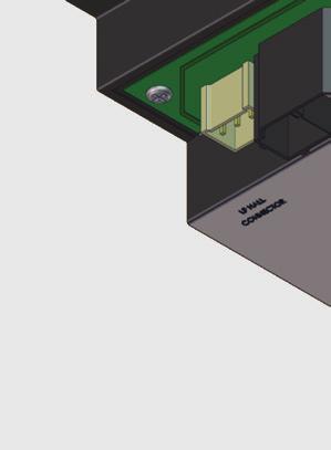
6 3. ttach the mounting plate (Fig. 7) and sensor (Fig. 7C) assembly to the crossmember (Fig. 7D) using two 3 8" hex head self-tapping screws (Fig. 7). Ensure that the plate is centered side to side on the frame and that the sensor is oriented properly (Fig. 7). Fig. 7 x D x C 4. Connect the rear sensor harness to the connector on the rear sensor (Fig. 8 )and run the harness through the frame and up to the compartment where the controller will be mounted. Fig. 8 Rev: Page 6 Ground Control 3.0 OEM Installation Manual


. NoTE: Some")


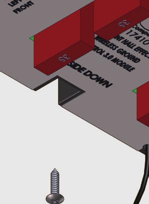

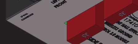
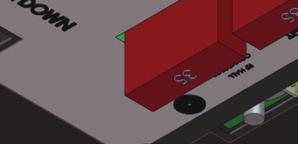

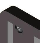
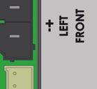
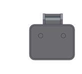
7 Installation - Controller NoTE: Prior to starting this portion of the installation, double check that all of the harnesses are properly and securely connected to the rear jacks, landing gear, and rear sensor. 1. Measure the ceiling of the compartment where the controller will be placed and mark the center point on the ceiling. The controller MUST be positioned directly in the center of the unit with the arrow on the label of the controller facing the front of the unit (Fig. 9). NoTE: Some 6-point controllers do not have orientation arrows for the front of the unit. When installing those controllers, ensure that the port labeled "LEFT FRONT" is pointing to the left-hand front of the unit. This will ensure proper orientation and function of the controller. 2. Using four #8 x 1 wood screws (Fig. 10), attach the controller (Fig. 10) to the ceiling of the compartment, centered over the marked centerline of the compartment. 3. ttach the power and ground harnesses to the corresponding posts on the controller and then connect them to the correct posts on the house battery. 4. Connect all jack harnesses to the appropriate connectors on the controller. Fig. 9 Fig. 10 Compartment Ceiling Rev: Page 7 Ground Control 3.0 OEM Installation Manual


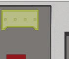
8 Installation - Touch Pad 1. Determine where to mount the touch pad. The touch pad should be mounted in a compartment on the side of the unit so the operator will have a view of the hitch pin while using the touch pad. 2. Remove the faceplate of the touch pad (Fig. 11) from the mounting bezel (Fig. 11). 3. Cut a hole in the wall of the compartment wide by 2 ¾ high (Fig. 12) so the top and bottom horizontal cuts are parallel to the floor of the compartment. Fig. 11 Fig. 12 Compartment Wall 2 ¾ " 3 3 8" 4. Feed the touch pad harness through this hole and run it to the compartment where the controller is mounted. Plug the harness into the appropriate connector on the controller. 5. Insert the touch pad bezel (Fig. 13) into the cutout and attach it with four #8x1" wood screws (Fig. 13) with sufficient length to thread into the compartment wall. 6. Plug the touch pad harness into the connector on the back of the touch pad faceplate and snap the faceplate into the bezel (Fig. 14). Fig. 13 Fig. 14 Rev: Page 8 Ground Control 3.0 OEM Installation Manual


9 Wiring Diagram - 4 Point Hall Effect Jack LCD Touch Pad Hall Effect Harness LCD Touch Pad Harness Rear Sensor Harness Rear Sensor Hall Effect Harness 4 Point Controller oem Supplied Circuit Interruption attery Hall Effect Landing Gear Rev: Page 9 Ground Control 3.0 OEM Installation Manual


10 Wiring Diagram - 6 Point Hall Effect Landing Gear LCD Touch Pad Rear Sensor Hall Effect Jack Rear Sensor Harness Touch Pad Harness Hall Effect Harness 6 Point Controller attery oem Supplied Circuit Interruption Hall Effect Jack Rev: Page 10 Ground Control 3.0 OEM Installation Manual


11 Touch Pad Diagram Fig. 15 E K C G D F H I J Callout C D E F G H I J K Description Up rrow - Scrolls up through the menu on LCD. Down rrow - Scrolls down through the menu on LCD. Enter - ctivates modes and procedures indicated on LCD. Retract - Places leveling system into retract mode. - Press and hold down for 1 second to initiate uto Retract. LCD Display - Displays procedures and results. uto Level - Places leveling system into auto level mode. Front Jack utton - ctivates front jacks in manual mode. Left Jack utton - ctivates left jacks in manual mode. Right Jack utton - ctivates right jacks in manual mode. Rear Jack utton - ctivates rear jacks in manual mode. Power utton - Turns leveling system on and off. Rev: Page 11 Ground Control 3.0 OEM Installation Manual
12 operation asic Jack Operation Landing gear jacks can be operated any time the system is ON. y pushing the FRONT button (Fig. 15G), both front or landing gear jacks can be extended. y pushing either the "FRONT" and LEFT (Fig. 15H) or "FRONT" and RIGHT (Fig. 15I) buttons, the individual front jacks can be extended. If the touch pad is put in the retract mode, indicated by the orange illuminated LED next to the RETRCT button (Fig. 15D), the front jacks can be retracted together by pushing the FRONT button (Fig. 15G) or individually by pressing LEFT (Fig. 15H) or RIGHT (Fig. 15I) buttons, while simultaneously pressing the FRONT button (Fig. 15G). NoTE: Middle jacks can only be operated in error mode. In order to engage middle jacks, press "LEFT" and "RIGHT" buttons simultaneously. The rear jacks can only be extended when the touch pad is in the manual mode. Once system is in manual mode, pressing the RER button (Fig. 15J) will extend both rear jacks at the same time. To extend individual rear jacks, press the LEFT (Fig. 15H) or RIGHT (Fig. 15I) buttons while simultaneously pressing the RER button (Fig. 15J), depending on which jack needs to be operated. If the touch pad is put in the retract mode, indicated by the orange illuminated LED next to the RETRCT button (Fig. 15D), the rear jacks can be retracted together by pushing the RER button (Fig. 15J) or individually by pressing either the LEFT (Fig. 15H) or RIGHT (Fig. 15I) buttons, while simultaneously pressing the RER button (Fig. 15J). NoTE: If the rear jacks will not operate individually using the method described above, but they operate properly when uto Level is performed, the Twist Prevention Protection system has locked out the operation to prevent damage to the frame of the unit. Homing Jacks 1. Introduce an error - disconnect one of the hall effect sensor wires at the controller. 2. ttempt to operate the jack that is associated with the sensor wire that was disconnected. The touch pad screen will display an error for that jack. 3. Reconnect the hall effect sensor wire. Manually extend all jacks down a minimum of 6 inches. 4. Press and hold the retract button until all of the jacks begin to retract. The jacks will retract until they reach the hard current limit. 5. The jacks are now homed. NoTE: If the jacks do not retract, an error should display on the touch pad screen. This is typically caused by wiring interruption. NoTE: In order to "home" jacks, middle jacks MUST also be extended. Refer to asic Jack Operation for middle jack operation. Rev: Page 12 Ground Control 3.0 OEM Installation Manual


 five (5) times and then press and release the RER button (Fig.")

. 6.")
.")

 inches, then press and hold the RETRCT")

13 Zero Point Calibration The Zero Point is the programmed point that the unit will return to each time the uto Level feature is used. The Zero Point MUST be programmed prior to using the uto Level feature to ensure the proper operation of the system. NoTE: Prior to starting this procedure, double check all connections on the controller, jacks, and touch pad. 1. Manually run the jacks to level the unit. This is best achieved by placing a level in the center of the unit and leveling it both front to back and then side to side. (See asic Jack Operation for instructions on how to manually operate the system). 2. Once the unit is level, turn off the touch pad. 3. With the touch pad off, press and release the FRONT button (Fig. 15G) five (5) times and then press and release the RER button (Fig. 15J) five (5) times. 4. The touch pad will flash and beep and the display will read ZERO POINT CLIRTION ENTER to set, Power to Exit (Fig. 16). 5. To set the current position as the zero point, press the ENTER button (Fig. 15C). 6. LCD display will read Zero Point stability check (Fig. 17). 7. LCD display will read Zero point set successfully once process is complete (Fig. 18). 8. The system will set this point as its level state and the touch pad will turn off. Fig. 16 Fig. 17 Fig. 18 Special Jack Error Codes To clear one of these errors: 1. Correct or otherwise repair the issue (see the table below). 2. Extend all of the jacks at least six (6) inches, then press and hold the RETRCT button on the touch pad until the jacks begin retracting. 3. ll of the jacks will retract fully to clear the error. LCD Message What's Happening? What Should e Done? ***ERROR*** LF Jack RF Jack LM Jack RM Jack LR Jack RR Jack Error at a specific jack (left front, right front, left rear, right rear). Hall signal issue (open, short, malfunction). Unexpected high amp current stall. Check harness connections at controller and at jack. Check harness for damage. Repair or replace as necessary. Rev: Page 13 Ground Control 3.0 OEM Installation Manual
14 Touch Pad Error Codes Note: To clear an error from the touch pad, repair or otherwise correct the issue, then press ENTER. If the error is still present, the message will be displayed again. LCD Message What's Happening? What Should e Done? Controller not properly secured. Check and secure controller placement. Excess ngle Excessive angle reached during Relocate the coach. auto operation. Excessive ngle Feature Disabled Low Voltage Out Of Stroke External Sensor Jack Time Out uto Level Fail ad Calibration Internal Sensor **PNIC STOP** Function borted Controller not properly secured. Excessive angle reached during auto operation. Front of coach below level when starting uto Level process (only when trying to initiate Hitch Recognition). Touch pad power not cycled between consecutive leveling operations. Zero point not set. attery voltage dropped below 10.8V. Jack has reached maximum stroke length and is unable to lift. ad connection or wiring from the controller to the rear sensor. Time limit exceeded for the requested auto operation. Unable to auto level due to uneven ground. Unable to auto level due to zero point being set incorrectly. Sensor calibration values are out of range. Internal sensor problem. The user pressed a button on the touch pad during an automatic operation. Check and secure controller placement. Relocate the coach. Raise front of coach above level and restart uto Level process. Turn touch pad off and then back on to reset the system. Set zero point. Check wiring for loose connections. Test battery voltage under load - charge or replace. Check disposition of jacks. Relocate the coach. Replace or repair connection to rear remote sensor. Check disposition of jacks. Check disposition of jacks. Relocate the coach. Reset zero point. Reset zero point. Replace controller. Restart automatic operation and then refrain from pressing any buttons on the touch pad. Rev: Page 14 Ground Control 3.0 OEM Installation Manual

15 The contents of this manual are proprietary and copyright protected by Lippert Components, Inc. ( LCI ). LCI prohibits the copying or dissemination of portions of this manual unless prior written consent from an authorized LCI representative has been provided. ny unauthorized use shall void any applicable warranty. The information contained in this manual is subject to change without notice and at the sole discretion of LCI. Revised editions are available for free download from Please recycle all obsolete materials. For all concerns or questions, please contact Lippert Components, Inc. Ph: (574) Web: warranty@lci1.com Rev: Page 15 Ground Control 3.0 OEM Installation Manual
OEM INSTALLATION MANUAL
 Ground Control 3.0 (5th Wheel) 4 Point and 6 Point OEM INSTLLTION MNUL Rev: 06.15.2016 Page 1 Ground Control 3.0 5th Wheel OEM Installation Manual TLE OF CONTENTS System and Safety Information 2 Preparation
Ground Control 3.0 (5th Wheel) 4 Point and 6 Point
 4 Point and 6 Point") Ground Control 3.0 (5th Wheel) 4 Point and 6 Point OEM INSTLLTION MNUL Rev: 11.13.2017 Page 1 Ground Control 3.0 5th Wheel OEM Installation Manual (2) TLE OF CONTENTS System and Safety Information 2 Preparation
Ground Control 3.0 (5th Wheel) 4 Point and 6 Point OEM INSTLLTION MNUL Rev: 11.13.2017 Page 1 Ground Control 3.0 5th Wheel OEM Installation Manual (2) TLE OF CONTENTS System and Safety Information 2 Preparation
Level-Up LCD 5th Wheel TROUBLESHOOTING GUIDE
 Level-Up LCD 5th Wheel TROULESHOOTING GUIDE TLE OF CONTENTS Introduction 2 System and Safety Information 2 Prior to Operation 2 Components 3 5 th Wheel Operation 5 Unhitching the Trailer From Tow Vehicle
Aftermarket Manual. Aftermarket Manual. Table Of Contents. Ground Control 3.0
 ftermarket Manual Ground Control 3.0 ftermarket Manual Table Of Contents Introduction................................... 2 Fully utomatic Electric Leveling System 2 Quick Facts 2 Parts List......................................
Ground Control TT Leveling System OWNER'S MANUAL
 Ground Control TT Leveling System OWNER'S MNUL TBLE OF CONTENTS System Information 2 Features 2 Safety Information 2 Touch Pad Diagram 3 Operation 4 Basic Jack Operation 4 Unhitching From Tow Vehicle 4
Ground Control TT Leveling with LCD Touch Pad
 Ground Control TT Leveling with LCD Touch Pad OEM INSTLLTION MNUL Rev: 11.29.2018 Page 1 TLE OF CONTENTS Safety Information 3 Resources Required 3 Measuring Departure and pproach ngle 4 Installation 5
Ground Control and 6 Point OneControl Touch Panel
 Ground Control 3.0 4 and 6 Point OneControl Touch Panel OEM INSTLLTION MNUL (For systems installed after June 1, 2018) TLE OF CONTENTS System Information 3 Safety Information 3 Resources Required 3 Preparation
Level-Up Motorhome Leveling
 Level-Up Motorhome Leveling Rev: 08.06.18 Page 1 CCD-0001751 TABLE OF CONTENTS Introduction 3 Components 3 Operation 5 Selecting a Site 5 Automatic Leveling Procedure 5 Automatic Leveling Descriptive Logic
Ground Control 3.0 (5th Wheel) 4 Point and 6 Point OneControl Touch Panel OWNER'S MANUAL
 4 Point and 6 Point OneControl Touch Panel OWNER'S MANUAL") Ground Control 3.0 (5th Wheel) 4 Point and 6 Point OneControl Touch Panel OWNER'S MNUL TBLE OF CONTENTS System Information 3 Safety Information 3 Touch Pad Diagram - uto Leveling Control Touch Pad 3 Operation
Ground Control 3.0 (5th Wheel) 4 Point and 6 Point OneControl Touch Panel OWNER'S MNUL TBLE OF CONTENTS System Information 3 Safety Information 3 Touch Pad Diagram - uto Leveling Control Touch Pad 3 Operation
Level-Up (Towable) System
 System") Level-Up (Towable) System OWNER'S MANUAL Rev: 12.21.2017 Page 1 Level-Up Towable Owner's Manual TABLE OF CONTENTS System and Safety Information 2 Introduction 3 Touch Pad Diagram 3 Prior to Operation 4
Level-Up (Towable) System OWNER'S MANUAL Rev: 12.21.2017 Page 1 Level-Up Towable Owner's Manual TABLE OF CONTENTS System and Safety Information 2 Introduction 3 Touch Pad Diagram 3 Prior to Operation 4
G C G III. OE Installation Manual
 G C G III OE Installation Manual 2 Table of Contents Installing Rear Jacks/Sensor 3 Installing Control Module/Interface 4 Programming the System 5 Parts Diagram and BOM 6 Wiring Diagram 7 NOTE: The front
PSX2 (Power Stabilizing System) OEM INSTALLATION MANUAL
 OEM INSTALLATION MANUAL") PSX2 (Power Stabilizing System) OEM INSTLLTION MNUL Rev: 10.24.2018 PSX2 OEM TLE OF CONTENTS Safety Information 2 System Description 3 Installation 3 Resources Required 3 Determine Stabilizer Locations
PSX2 (Power Stabilizing System) OEM INSTLLTION MNUL Rev: 10.24.2018 PSX2 OEM TLE OF CONTENTS Safety Information 2 System Description 3 Installation 3 Resources Required 3 Determine Stabilizer Locations
Level-Up With OneControl Touch Panel OWNER'S MANUAL
 Level-Up With OneControl Touch Panel OWNER'S MNUL Table of Contents System Information 2 Safety Information 3 Touch Pad Diagram - uto Leveling Control 3 Red/Green LED Indicator 3 Operation - uto Leveling
Tire Linc OEM INSTALLATION MANUAL
 Tire Linc OEM INSTLLTION MNUL Introduction The Tire Linc tire pressure monitoring system is a wireless system that automatically monitors tire pressure and temperature. If any abnormalities are detected,
Aftermarket Manual. Aftermarket Manual. Level-Up. Table of Contents. Level-Up
 Level-Up Aftermarket Manual Table of Contents Quoting Level Up Systems.... 2 Preparation.... 2 Installation... 4 Rear Jacks... 4 Rear Sensor... 6 Front Landing Gear... 7 Power Unit... 8 Assembling and
Level Up. Level Up Installation and Owner s Manual. Installation and Owner s Manual (For Aftermarket Applications)
") Level Up Installation and Owner s Manual (For Aftermarket Applications) THE LEVEL UP SYSTEM FOR 5TH WHEELS IS ONLY AUTHORIZED FOR INSTALLATION ON LCI BRAND FRAMES WITH AN I-BEAM OF 8 INCHES OR GREATER
Level Up Installation and Owner s Manual (For Aftermarket Applications) THE LEVEL UP SYSTEM FOR 5TH WHEELS IS ONLY AUTHORIZED FOR INSTALLATION ON LCI BRAND FRAMES WITH AN I-BEAM OF 8 INCHES OR GREATER
Electric Stabilizer Jack
 Electric Stabilizer Jack OWNER'S MANUAL Rev: 10.09.2017 Page 1 Electric Stabilizer Jack Owners Manual TABLE OF CONTENTS System 2 System Description 3 Operation 3 Extending Stabilizer Jack 3 Retracting
Level Up. Level Up Installation and Owner s Manual. Installation and Owner s Manual (For Aftermarket Applications) Table of Contents
 Table of Contents") Level Up Installation and Owner s Manual (For Aftermarket Applications) The Aftermarket Level Up system can only be installed on a Lippert chassis. Table of Contents System and Safety Information... 2
Level Up Installation and Owner s Manual (For Aftermarket Applications) The Aftermarket Level Up system can only be installed on a Lippert chassis. Table of Contents System and Safety Information... 2
Standalone Smart Jack OEM INSTALL MANUAL. Rev: Page 1 Standalone Smart Jack OEM Install Manual
 Standalone Smart Jack OEM INSTLL MNUL Rev: 09.23.2016 Page 1 Standalone Smart Jack OEM Install Manual TBLE OF CONTENTS Safety Information 2 Product Information 2 Resources Required 2 Preparation 3 Installation
Ground Control 3.0 Landing Gear
 Ground Control 3.0 Landing Gear OEM INSTALLATION MANUAL Rev: 12.28.2017 Page 1 TABLE OF CONTENTS Safety and System Information 2 Installation 3 Landing Gear 3 Wiring Landing Gear 4 Wiring Diagram 5 Operation
Easy Approach OEM INSTALLATION MANUAL (FOREST RIVER)
") Easy pproach OEM INSTLLTION MNUL (FOREST RIVER) Introduction TBLE OF CONTENTS Introduction 2 Safety 3 Resources Required 3 Installation 4 Fully ssembled xle Sub-Frame 4 Installing the Hydraulic System
Easy pproach OEM INSTLLTION MNUL (FOREST RIVER) Introduction TBLE OF CONTENTS Introduction 2 Safety 3 Resources Required 3 Installation 4 Fully ssembled xle Sub-Frame 4 Installing the Hydraulic System
PSX2 (Power Stabilizing System) OWNER'S MANUAL
 OWNER'S MANUAL") PSX2 (Power Stabilizing System) OWNER'S MANUAL TABLE OF CONTENTS Safety Information 2 System Description 3 Operation 3 Preparation 3 Extending Stabilizers 4 Retracting Stabilizers 4 Stabilizing System
PSX2 (Power Stabilizing System) OWNER'S MANUAL TABLE OF CONTENTS Safety Information 2 System Description 3 Operation 3 Preparation 3 Extending Stabilizers 4 Retracting Stabilizers 4 Stabilizing System
Hitch Receiver OEM INSTALLATION MANUAL
 Hitch Receiver OEM INSTALLATION MANUAL TABLE OF CONTENTS Introduction 2 Safety 3 Resources Required 3 Installation 4 2" and 2 1/2" Accessory Hitch Receiver 4 Bike Rack /Accessory Hitch Receiver 6 Boat
Ground Control 3.0 Landing Gear OEM INSTALLATION MANUAL
 Ground Control 3.0 Landing Gear OEM INSTALLATION MANUAL TABLE OF CONTENTS Safety and System Information 2 Installation 3 Landing Gear 3 Wiring Landing Gear 4 Wiring Diagram 5 Operation 6 Prior to Operation
LCI4A3LCD Hydraulic Leveling
 LCI4A3LCD Hydraulic Leveling OWNER'S MANUAL with LCD Touch Pad (4-Point/3-Valve - Motorized) TABLE OF CONTENTS System Information 3 Component Description 3 Safety Information 3 Operation 4 Selecting A
Schwintek Bunk Lift INSTALLATION MANUAL. Rev: Page 1 Schwintek Bunk Lift OEM Installation Manual
 Schwintek Bunk Lift INSTALLATION MANUAL Rev: 02.03.2017 Page 1 Schwintek Bunk Lift OEM Installation Manual TABLE OF CONTENTS Introduction 3 Required Components 3 Important Notes 3 Installation 4 Bearing
Ice House Axle OEM INSTALLATION MANUAL
 Ice House xle OEM INSTLLTION MNUL TLE OF CONTENTS System Information 2 Tools required 2 Hardware Required 2 Grease Specifications 2 Prior to Installation 3 Installation 4 Maintenance Schedule 8 Notes 9
Ground Control 3.0 Landing Gear OWNER'S MANUAL
 Ground Control 3.0 Landing Gear OWNER'S MANUAL Rev: 07.02.2018 TABLE OF CONTENTS System Information 2 Operation 2 Prior to Operation 2 Extending Landing Gear 3 Retracting Landing Gear 3 Troubleshooting
Flip Automatic Jack Foot
 Flip Automatic Jack Foot OEM INSTALLATION MANUAL Rev: 12.28.2017 Page 1 Flip Automatic Jack Foot OEM Installation Manual TABLE OF CONTENTS System Information 2 Safety Information 2 Resources Required 2
Triple Play Ramp Door OEM INSTALLATION MANUAL
 Triple Play Ramp Door OEM INSTLLTION MNUL TLE OF CONTENTS Introduction 2 Safety Information 3 Resources Required 3 Installation 4 Doorjamb 4 Hidden Hinge Installation 7 Door Cable System 8 Electrical Connections
Intelli-view Tank Monitor
 Intelli-view Tank Monitor INSTALLATION MANUAL Rev: 02.17.2017 Page 1 Intelliview Tank Monitor Install Manual TABLE OF CONTENTS System 2 Safety Information 2 Intelli-view Tank Monitor Panel Installation
Sway Command Tow Control System (For Travel Trailer) OEM INSTALL MANUAL. Rev: Page 1 Sway Command OEM Install Manual
 OEM INSTALL MANUAL. Rev: Page 1 Sway Command OEM Install Manual") Sway Command Tow Control System (For Travel Trailer) OEM INSTLL MNUL Rev: 09.17.2015 Page 1 Sway Command OEM Install Manual TBLE OF CONTENTS Introduction 2 Causes of Sway 2 Preparation 3 Tools and Hardware
Sway Command Tow Control System (For Travel Trailer) OEM INSTLL MNUL Rev: 09.17.2015 Page 1 Sway Command OEM Install Manual TBLE OF CONTENTS Introduction 2 Causes of Sway 2 Preparation 3 Tools and Hardware
In-Wall Slide-Out (Winnebago Version) OWNER'S MANUAL
 OWNER'S MANUAL") In-Wall Slide-Out (Winnebago Version) OWNER'S MANUAL TABLE OF CONTENTS System and Safety Information 2 Safety Information 2 Operation 3 Prior to Operation 3 Extending Slide-out Room 3 Retracting Slide-out
In-Wall Slide-Out (Winnebago Version) OWNER'S MANUAL TABLE OF CONTENTS System and Safety Information 2 Safety Information 2 Operation 3 Prior to Operation 3 Extending Slide-out Room 3 Retracting Slide-out
Class C Hydraulic Leveling System OEM INSTALLATION MANUAL
 Class C Hydraulic Leveling System OEM INSTALLATION MANUAL TABLE OF CONTENTS System Information 3 Component Description 3 Safety Information 3 Prior to Operation 4 Preparation 4 Installation 5 Prior to
In-Wall Slide-out COMPONENT ASSEMBLY MANUAL
 In-Wall Slide-out COMPONENT SSEMLY MNUL TLE OF CONTENTS System Information 2 Safety Information 2 Resources Required 2 Motor Removal 2 Timing Procedure 3 Installing Shipping ngles 4 Notes 5 System Information
LCI4A3LCD Hydraulic Leveling (Sprinter Bolt- On Mounting Bracket) OEM INSTALLATION MANUAL
 OEM INSTALLATION MANUAL") LCI4A3LCD Hydraulic Leveling (Sprinter Bolt- On Mounting Bracket) OEM INSTALLATION MANUAL TABLE OF CONTENTS System Information 3 Component Description 3 Safety Information 4 Preparation 5 Tools Required
LCI4A3LCD Hydraulic Leveling (Sprinter Bolt- On Mounting Bracket) OEM INSTALLATION MANUAL TABLE OF CONTENTS System Information 3 Component Description 3 Safety Information 4 Preparation 5 Tools Required
LCI Level-Up Motorhome Leveling (2013-Present) OWNER'S MANUAL. Rev: Page 1 LCILevel-Up MotorhomeLeveling (2013-Present)OwnersManual
 OWNER'S MANUAL. Rev: Page 1 LCILevel-Up MotorhomeLeveling (2013-Present)OwnersManual") LCI Level-Up Motorhome Leveling (2013-Present) OWNER'S MANUAL Rev: 05.23.2016 Page 1 LCILevel-Up MotorhomeLeveling (2013-Present)OwnersManual TABLE OF CONTENTS System Information 3 Prior To Operation 3
LCI Level-Up Motorhome Leveling (2013-Present) OWNER'S MANUAL Rev: 05.23.2016 Page 1 LCILevel-Up MotorhomeLeveling (2013-Present)OwnersManual TABLE OF CONTENTS System Information 3 Prior To Operation 3
SCHWINTEK TV LIFT (AUSTRALIA) INSTALLATION MANUAL
 INSTALLATION MANUAL") SCHWINTEK TV LIFT (AUSTRALIA) INSTALLATION MANUAL TABLE OF CONTENTS Safety Information 2 Resources Required 2 Schwintek TV Lift Installation 3-4 Programming the Extend and Retract Stops 5 Operation 5 Schwintek
SCHWINTEK TV LIFT (AUSTRALIA) INSTALLATION MANUAL TABLE OF CONTENTS Safety Information 2 Resources Required 2 Schwintek TV Lift Installation 3-4 Programming the Extend and Retract Stops 5 Operation 5 Schwintek
SlimRack Bed Lift System OEM INSTALLATION MANUAL
 SlimRack Bed Lift System OEM INSTALLATION MANUAL Rev: 07.11.2018 TABLE OF CONTENTS System Information 2 Safety Information 3 Resources Required 3 General Requirements 3 Installation 4 SlimRack Bed Lift
X-Ramp Hydraulic Lowering System OEM INSTALLATION MANUAL
 X-Ramp Hydraulic Lowering System OEM INSTLLTION MNUL TBLE OF CONTENTS Introduction 2 Safety Requirements 2 Resources Required 3 Preparation 3 Installation 3 Fully ssembled xle Sub-Frame 3 Welding xle Sub-Frame
Lexington L-Shaped Expandable Lounge OWNER'S MANUAL
 Lexington L-Shaped Expandable Lounge OWNER'S MANUAL TABLE OF CONTENTS Introduction 2 Safety 2 Operation 2 Expanding L-Lounge 2 Retracting L-Lounge 5 Notes 9 Introduction This owner's manual describes the
Patriot Jack Systems OWNER'S MANUAL
 Patriot Jack Systems OWNER'S MANUAL TABLE OF CONTENTS Introduction 2 Operation 3 Dual Jack Two-Valve System 3 Dual Jack One-Valve System 3 Single Jack One-Valve System 3 Preventive Maintenance 4 Adding
In-Wall Slide-Out OWNER'S MANUAL. Rev: Page 1 In-Wall Slide-out Owner's Manual
 In-Wall Slide-Out OWNER'S MANUAL Rev: 04.12.2017 Page 1 In-Wall Slide-out Owner's Manual TABLE OF CONTENTS Safety Information 3 Operation 3 Prior To Operation 3 Extending Slide-Out Room 4 Retracting Slide-Out
Patriot Jack Systems OEM INSTALLATION MANUAL
 Patriot Jack Systems OEM INSTALLATION MANUAL TABLE OF CONTENTS Introduction 2 Resources Required 2 Jack, Switch Installation 3 Dual Jack Two-Valve System 4 Connect Hoses 4 Electrical Connections 4 Operation
Compact Triple Electric Step OWNERS MANUAL
 Compact Triple Electric Step OWNERS MANUAL TABLE OF CONTENTS Safety Information 2 Product Information 3 Operation 3 Installation 3 Removal of Existing Step 3 Extending Step Assembly 3 Wiring the Step 4
SlimRack Bed Lift System OWNER'S MANUAL
 SlimRack Bed Lift System OWNER'S MANUAL TABLE OF CONTENTS System Information 2 Features 2 Operation 3 Prior to Operating the SlimRack Bed Lift System 3 Raising the Bed 3 Lowering the Bed 3 Troubleshooting
LCI Motorized Leveling - Unidirectional (2009-Present)
") LCI Motorized Leveling - Unidirectional (2009-Present) OWNER'S MANUAL Rev: 07.09.2018 LCI Motorized Leveling (2009 - Present) Owner's Manual TABLE OF CONTENTS SYSTEM 3 Prior to Operation 3 System Description
LCI Motorized Leveling - Unidirectional (2009-Present) OWNER'S MANUAL Rev: 07.09.2018 LCI Motorized Leveling (2009 - Present) Owner's Manual TABLE OF CONTENTS SYSTEM 3 Prior to Operation 3 System Description
Sway Command Tow Control System
 Sway Command Tow Control System (For Travel Trailer) OEM INSTLLTION MNUL TBLE OF CONTENTS Introduction 2 Causes of Sway 2 Preparation (Non-Prepped Trailer) 3 Resources Required 3 Components Required 3
Class C Hydraulic Leveling System OEM INSTALLATION MANUAL
 Class C Hydraulic Leveling System OEM INSTALLATION MANUAL TABLE OF CONTENTS System Information 3 Component Description 3 Safety Information 3 Prior to Operation 4 Preparation 4 Installation 5 Prior to
Coachstep OWNER'S MANUAL
 Coachstep OWNER'S MANUAL TABLE OF CONTENTS System and Safety Information 3 Operation 4 Maintenance 4 How to Adjust Cams 4 Lubrication 4 Coachstep Gear Plate and Bolt Replacement 5 Coachstep Motor Replacement
ULTRA LEVEL MOTORIZED LEVELING
 ULTRA LEVEL MOTORIZED LEVELING OWNER'S MANUAL Page 1 TABLE OF CONTENTS SYSTEM 3 Prior to Operation 3 System Description 3 Features 3 Fluid Recommendation 4 Component Description 4 System Wiring Requirements
Ice House Axle OEM INSTALLATION MANUAL
 Ice House xle OEM INSTLLTION MNUL TLE OF CONTENTS System Information 2 Resources Required 2 Installation 3-7 Maintenance Schedule 8 Notes 9 System Information This manual will detail the procedure for
Bauer NE Lock OWNER'S MANUAL
 Bauer NE Lock OWNER'S MNUL TBLE OF CONTENTS Product Information 2 Features 2 Operation 3 Calibration and Programming 3 Preset Factory Code 3 Programming New Code 3 Maintenance 3 Installation 4 Bauer NE
F.A.S.T. Ramp Rear Door SERVICE MANUAL
 F..S.T. Ramp Rear Door SERVICE MNUL TBLE OF CONTENTS Introduction 2 Safety Information 2 Resources Required 3 Operation 3 Removing Old Cable 3 Inserting New Cable 5 Notes 7 Introduction The following information
Embedded Rack Slide-out System
 Embedded Rack Slide-out System SERVICE MANUAL Rev: 02.16.2017 Page 1 Electric Embedded Rack Slide-out System TABLE OF CONTENTS Safety Information 3 Product Information 3 Operation 4 Extending Slide-Out
Equa-Flex Tandem and Triple OEM INSTALLATION MANUAL
 Equa-Flex Tandem and Triple OEM INSTALLATION MANUAL TABLE OF CONTENTS System Information 2 Tandem Axle Options 2 Triple Axle Options 2 Safety Information 2 Resources Required 3 Installation 3 Tandem Axle
Self-Deploying Rail Kit OEM INSTALLATION MANUAL
 Self-Deploying Rail Kit OEM INSTLLTION MNUL TLE OF ONTENTS Introduction 2 Safety Information 2 Resources Required 3 Prior to Installation 3 Installation 3 Doorjamb 3 Setting the Doorjamb 3 inch Latch 4
EuroLoft Bed Lift OWNER'S MANUAL
 EuroLoft Bed Lift OWNER'S MANUAL TABLE OF CONTENTS System Information 2 Safety Information 2 Important Safety Information 2 Operation 3 Prior to Operating the EuroLoft Bed Lift System 3 Lowering the Bed
Sway Command Tow Control System OWNER'S MANUAL
 Sway Command Tow Control System OWNER'S MANUAL TABLE OF CONTENTS System Components 2 Introduction 3 Causes of Sway 3 Prior to Operation 3 Sway Command Controller Operation 4 Light Codes and Troubleshooting
In-Wall Slide-Out (Winnebago)
") In-Wall Slide-Out (Winnebago) REPIR MNUL Rev: 11.16.2017 Page 1 Winnebago In-Wall Repair Manual 22MR17 TBLE OF CONTENTS Safety Information 2 Introduction 2 Preliminary Visual Inspection 3 ssembly Removal
In-Wall Slide-Out (Winnebago) REPIR MNUL Rev: 11.16.2017 Page 1 Winnebago In-Wall Repair Manual 22MR17 TBLE OF CONTENTS Safety Information 2 Introduction 2 Preliminary Visual Inspection 3 ssembly Removal
LCI Motorized Leveling ( )
") ED U TI N LCI Motorized Leveling (2002-2008) D IS C O N OWNER'S MANUAL Rev: 12.27.2017 Page 1 LCI Motorized Leveling (02-08) Owner's Manual TABLE OF CONTENTS System 3 System Description 3 Component Description
ED U TI N LCI Motorized Leveling (2002-2008) D IS C O N OWNER'S MANUAL Rev: 12.27.2017 Page 1 LCI Motorized Leveling (02-08) Owner's Manual TABLE OF CONTENTS System 3 System Description 3 Component Description
SlimRack Slide-out COMPONENTS ASSEMBLY MANUAL. Rev: Page 1 SlimRack Components Assembly Manual
 SlimRack Slide-out COMPONENTS ASSEMBLY MANUAL Rev: 11.16.2017 Page 1 SlimRack Components Assembly Manual TABLE OF CONTENTS Product Information 2 Additional Warranty Exclusions 2 Safety Information 2 Resources
In-Wall Slide-Out REPAIR KIT MANUAL. Rev: Page 1 In-Wall Repair Kits Manual
 In-Wall Slide-Out REPAIR KIT MANUAL Rev: 02.16.2017 Page 1 In-Wall Repair Kits Manual TABLE OF CONTENTS Safety Information 2 Introduction 2 Preliminary Visual Inspection 3 Assembly Removal Procedure 4
Road Armor Triple Axle Equalizer by Trailair
 Road Armor Triple Axle by Trailair OEM INSTALLATION MANUAL Rev: 06.26.2017 Page 1 TABLE OF CONTENTS System Information 2 Triple Axle Options 2 Safety Information 2 Resources Required 2 Installation 3 Rear
F.A.S.T. Track Flush Floor Slide-out. (Fast Assembly Self Tensioning) OWNER'S MANUAL
 OWNER'S MANUAL") F..S.T. (Fast ssembly Self Tensioning) Track Flush Floor Slide-out OWNER'S MNUL TBLE OF CONTENTS System Information 2 Major Components 2 Safety Information 3 Prior to Operation 3 Operation 4 Extending
F..S.T. (Fast ssembly Self Tensioning) Track Flush Floor Slide-out OWNER'S MNUL TBLE OF CONTENTS System Information 2 Major Components 2 Safety Information 3 Prior to Operation 3 Operation 4 Extending
Power Tongue Jack OWNER'S MANUAL
 Power Tongue Jack OWNER'S MANUAL TABLE OF CONTENTS Product Information 2 Safety 3 Operation 4 Unhitching From Tow Vehicle 4 Hitching to Tow Vehicle 4 Manual Operation 5 Troubleshooting 6 Fuse 6 Clutch
IMGL and 9510 Control Replacement Kit #214 INSTALLATION MANUAL
 IMGL and 9510 Control Replacement Kit #214 INSTALLATION MANUAL TABLE OF CONTENTS Safety Information 2 Product Information 2 Removal and Replacement of IMGL Assembly 4 Removal and Replacement of The Control
OEM INSTALLATION MANUAL
 Waste Master OEM INSTALLATION MANUAL Rev: 09.04.2015 Page 1 Waste Master Installation Manual TABLE OF CONTENTS Introduction 2 Installation of System 3 Prior To Storage Box Installation 4 Storage Box Installation
Hydro-Sync Slide-Out System
 Hydro-Sync Slide-Out System SERVICE MANUAL Rev: 08.14.2018 Hydro-Sync Slide-out System Service Manual TABLE OF CONTENTS Safety Information 3 Product Information 3 Operation 4 Extending Slide-Out Room 4
Solera Power Awning TROUBLESHOOTING AND SERVICE MANUAL
 Solera Power Awning TROUBLESHOOTING AND SERVICE MANUAL Table of Contents System and Safety Information 2 Basic Troubleshooting 3 Service and Replacement 4 Support Arm Assembly Replacement 4 Changing (Remove
Kwikee IMGL Step Control Testing Procedure #82-ST0500
 Kwikee IMGL Step Control Testing Procedure #82-ST0500 TABLE OF CONTENTS Introduction 2 Resources Required 2 General Service Notes 3 Preparation 5 Troubleshooting and Test Procedures 5 Testing the Step
Trailer Axle Beam Replacement SERVICE MANUAL
 Trailer Axle Beam Replacement SERVICE MANUAL September 20, 2017 Trailer Axle Beam Service Manual TABLE OF CONTENTS System Information 2 Safety Information 2 Required Resources 2 Hub Removal 3 Axle Beam
EuroLoft Bed Lift OWNER'S MANUAL
 EuroLoft Bed Lift OWNER'S MANUAL TABLE OF CONTENTS System Information 2 Safety Information 2 Important Safety Information 2 Operation 3 Prior to Operating the EuroLoft Bed Lift System 3 Lowering the Bed
Kwikee Revolution Step Series
 Kwikee Revolution Step Series OWNER'S MANUAL (3010002262) Rev: 07.26.2018 Kwikee Revolution Step Series Owner's Manual 3010002262 TABLE OF CONTENTS Safety Information 2 Product Information 2 General Service
Kwikee Platinum Series OWNER'S MANUAL
 Kwikee Platinum Series OWNER'S MANUAL TABLE OF CONTENTS Safety Information 2 Product Information 2 General Service Notes 3 Prior To Operation 3 Operation 4 Step with Control Unit 4 Troubleshooting 5 Step
Turning Point Pin Box. by Trailair OWNER'S MANUAL
 Turning Point Pin Box by Trailair OWNER'S MANUAL TABLE OF CONTENTS Product and Safety Information 2 Preparation 3 Tow Rating Weights Check For 10,000 lbs Pin Box (Fig. 1) 3 Tow Rating Weights Check For
Waste Master OWNER'S MANUAL. Rev: Page 1 Waste Master Owner's Manual
 Waste Master OWNER'S MANUAL Rev: 06.15.2015 Page 1 Waste Master Owner's Manual TABLE OF CONTENTS Introduction 2 Operation 3 Service 4 Removing The Hose Assembly 4 Field Changing Of Waste Master Nozzle
KWIKEE #888 ELECTRIC STEP. Owner's Manual ( )
") KWIKEE #888 ELECTRIC STEP Owner's Manual (1422279) TABLE OF CONTENTS Safety Information 2 Motor Assembly Identification 3 Product Information 4 Steps With Control Unit 4 Steps Without Control Unit 4 General
KWIKEE #888 ELECTRIC STEP Owner's Manual (1422279) TABLE OF CONTENTS Safety Information 2 Motor Assembly Identification 3 Product Information 4 Steps With Control Unit 4 Steps Without Control Unit 4 General
5th Wheel Electric Leveling System
 LEVELING SYSTEM MADE IN USA MADE IN U.S.A. R V PR ODUC T S NORCO INDUSTRIES, INC. 5th Wheel Electric Leveling System 20300513 TABLE OF CONTENTS...2 STANDARD PROCEDURES & AUTOMATED FUNCTIONS...3 UNIT DETACHMENT
Kwikee # Series Step OWNER'S MANUAL ( )
") Kwikee #842 42 Series Step OWNER'S MANUAL (1422258) TABLE OF CONTENTS Safety Information 2 Product Information 3 Step with Control Unit 3 Operation 3 General Service 4 Prior To Operation 4 Adjusting Cam
Kwikee #842 42 Series Step OWNER'S MANUAL (1422258) TABLE OF CONTENTS Safety Information 2 Product Information 3 Step with Control Unit 3 Operation 3 General Service 4 Prior To Operation 4 Adjusting Cam
Above Floor Slide-out OEM INSTALLATION MANUAL
 bove Floor Slide-out OEM INSTLLTION MNUL TLE OF CONTENTS System Information 2 Safety Information 3 Resources Required 3 Installation 4 Prior to Installation 4 Installing the Slide-Out ssembly Onto the
Electric Through Frame Slide-Out
 Electric Through Frame Slide-Out OWNER'S MANUAL Rev: 11.13.2017 Page 1 Electric Through Frame Slide-out Owner's Manual TABLE OF CONTENTS Warning, Safety, and System Requirement Information 2 Description
Ground Control. TT Leveling OneControl Touch Panel Installation and Owner s Manual
 Table of ontents Introduction... 2 Features... 2 Safety Information... 2 Trailer Weight Rating... 2 Resources Required... 2 Parts List... 3 Measuring Departure and pproach ngle... 4 Installation... 4 olt
GRAIN CART RETROFIT TRACK SLIDE-IN-HITCH SCALE SYSTEM
 GRAIN CART RETROFIT TRACK SLIDE-IN-HITCH SCALE SYSTEM Instructions This manual is copyrighted by Scale-Tec. Redistribution or copy of this manual or portions of this manual must be approved through Scale-Tec
Flow Max Fluid Pump. by Duraself OEM INSTALLATION MANUAL
 Flow Max Fluid Pump by Duraself OEM INSTALLATION MANUAL TABLE OF CONTENTS System and Safety Information 2 Resources Required 3 Installation 3 General Installation Instructions 3 Mounting Instructions 3
Operator s Manual. Automatic Electric Jack Leveling. The leveling system shall only be operated under the following conditions:
 Operator s Manual with Automatic Leveling Touchpad #140-1226 Control Box #140-1224 co Copyright PowerGear 1/07 #82-L0368 Rev. 0D Contents Before You Level Your Coach 1 Caution 1 Leveling System Operating
Triple Play Ramp Door OWNER'S MANUAL
 Triple Play Ramp Door OWNER'S MANUAL TABLE OF CONTENTS Introduction 2 Safety Information 3 Operation 4 To Operate the Triple Play Ramp Door Touchpad: 5 Patio Mode 5 Ramp Mode 5 Closing the Triple Play
Control Replacement # Page 1 REPLACEMENT OF OBSOLETE SEMI- AUTO CONTROLS WITH KIT #
 Control Replacement #500643 Page 1 R epla c ement of s emi-a uto c ontr ols with r epla c ement kit # 500643 Content CONTENTS Control Replacement 2 Calibration 5 Operating Instructions 6 Preventive Maintenance
WIRELESS TRI-JACK WIRELESS REMOTE KIT COMPONENTS LITERATURE NUMBER REV. C WARNING EXPLOSION WARNING PERSONAL INJURY & PROPERTY DAMAGE
 LITERATURE NUMBER 8260. REV. C WIRELESS TRI-JACK Effective July 207 Installation Operation Maintenance SAFETY ALERT SYMBOLS Safety Symbols alerting you to potential personal safety hazards. Obey all safety
Hydraulic Through Frame Slide-out SERVICE MANUAL
 Hydraulic Through Frame Slide-out SERVICE MNUL TBLE OF CONTENTS Warning, Safety, and System Requirement Information 3 Description 3 Safety Information 3 Prior to Operation 4 Operation 4 Extending Slide-Out
HYDRAULIC LANDING GEAR REPLACEMENT
 Purpose This kit outlines the procedure to replace existing square hydraulic landing gear jacks, including square and round hydraulic, pin-less jacks. Square landing gear is no longer available. Required
Correct Track Suspension Alignment System
 Correct Track Suspension Alignment System Table Of Contents Introduction........................................... 2 Parts List.............................................. 2 Preparation............................................
WIRELESS CAMPER JACK LITERATURE NUMBER REV. C CCD WARNING PERSONAL INJURY & PROPERTY DAMAGE WARNING EXPLOSION. Effective NOV 2018
 LITERATURE NUMBER 670903. REV. C WIRELESS CAMPER JACK Effective NOV 2018 Installation Operation Maintenance SAFETY ALERT SYMBOLS Safety Symbols alerting you to potential personal safety hazards. Obey all
GRAIN CART RETROFIT J-M TRACK SLIDE IN HITCH SCALE SYSTEM
 GRAIN CART RETROFIT J-M TRACK SLIDE IN HITCH SCALE SYSTEM Instructions This manual is copyrighted by Scale-Tec. Redistribution or copy of this manual or portions of this manual must be approved through
Correct Track. Correct Track Installation and Owner s Manual. Installation and Owner s Manual (For Aftermarket Applications)
") Correct Track Installation and Owner s Manual Table of Contents Introduction... 2 Safety Information... 2 Parts List... 3 Triple Axle... 3 Tandem Axle... 3 Single Axle... 3 Prior to Installation... 4 Preparation...
Correct Track Installation and Owner s Manual Table of Contents Introduction... 2 Safety Information... 2 Parts List... 3 Triple Axle... 3 Tandem Axle... 3 Single Axle... 3 Prior to Installation... 4 Preparation...
GRAIN CART RETROFIT WELD-IN KIT SCALE SYSTEM
 GRAIN CART RETROFIT WELD-IN KIT SCALE SYSTEM Instructions This manual is copyrighted by Scale-Tec. Redistribution or copy of this manual or portions of this manual must be approved through Scale-Tec and
Automatic Electric Jack Leveling
 Contents Before You Level Your Coach 1 Caution Leveling System Operating Instructions -- Buttons and Operation 2 Lights & Function Indicators 2 Selecting A Site 2 Automatic Leveling 2 Manual Leveling 3
OPERATORS MANUAL for AUTOMATIC RV SYSTEM. Comment [KO1]:
![OPERATORS MANUAL for AUTOMATIC RV SYSTEM. Comment [KO1]:](/thumbs/80/81800064.jpg "OPERATORS MANUAL for AUTOMATIC RV SYSTEM. Comment [KO1]:") OPERATORS MANUAL for AUTOMATIC RV SYSTEM Comment [KO1]: 82 L0130 00 Rev. 2 July 2003 TABLE OF CONTENTS OPERATION AND MAINTENANCE...1 OPERATION CAUTION NOTES...1 BEFORE YOU OPERATE THE SYSTEM...2 SELECTING
OPERATORS MANUAL for AUTOMATIC RV SYSTEM Comment [KO1]: 82 L0130 00 Rev. 2 July 2003 TABLE OF CONTENTS OPERATION AND MAINTENANCE...1 OPERATION CAUTION NOTES...1 BEFORE YOU OPERATE THE SYSTEM...2 SELECTING
HYDRAULIC LEVELING SYSTEMS OPERATIONS MANUAL
 HYDRAULIC LEVELING SYSTEMS OPERATIONS MANUAL (For systems with touch pad part number 500675) touchpad 500675 82-L0140-00 REV.3 WARNING DO NOT USE THE POWER GEAR HYDRAULIC LEVELING SYSTEM (OR AIR SUSPENSION)
Operation Guide. Operation Guide. Winnebago Hydraulic Leveling Systems by Kwikee. Introduction. Table of Content WARNINGS
 Operation Guide 05/07 Kwikee #1422192 Rev. 0F Table of Content Page Introduction 1 Safety Information 1 Operation 2 Control Panel 3 Manual Leveling 3 Automatic Leveling 3 Remote Operation 4 Stabilizing