HD UNIT INSTALLATION & SERVICE BOOKLET 3-7
|
|
|
- Myra Owens
- 6 years ago
- Views:
Transcription

1 HD UNIT INSTALLATION & SERVICE BOOKLET 3-7
2 2
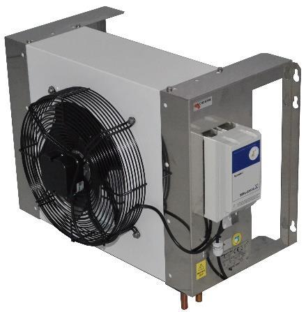
3 Heat exchanger Fan Mounting hole Speed control Air flow hole Technical information plate Power cable 230V Glycol inlet/outlet WARNING During the installation the heat dump unit should be disconnected from the el. main until the final installation and putting into function is done. USER INSTRUCTIONS User instruction consists of installation and usage instructions. This instruction is integral part of every cooler unit, and it should always be with the cooler and also during every displacement or installation, so technical personnel could use it. Before installation and usage of cooler, you should carefully read this user instruction in which there are important information for correct and safe use. Unit weight is 18 kg. NOTE: The unit should be installed and serviced by a suitably trained person. 1. Unpack the unit from its transportation packaging and visually inspect for signs of damage. 2. Site the heat dump in a convenient location, preferably in a non heat sensitive and shaded area on the outside of building. If it can not be installed outside, ensure that the area is free from other heat sources. The unit should be sited to allow free circulation of air. Height from the ground to base of unit should not exceed 9 metres. (30 feet) 3. Fix the unit to the wall. HEAT DUMP PIPES 1. Heat dump pipes are 15 mm and must be run with a space between the flow and return. 3
4 2. Only approved glycol tubing can be used. PVC pipes must never be used it is unsuitable for hot glycol. DISMANTLING DECOMMISSIONING PROCEDURE 1. Plug out the unit from Electricity Supply. 2. Disconnect the recirculating coolant Inlet/Outlet pipes. ADJUSTMENTS MAINTENANCE REQUIREMENTS It is not recommended that the end user makes any adjustments or carriers out any maintenance other than: 1. Check the mains lead and plug visually for condition. 2. Check the unit and its pipe work for evidence of leaks visually. METHODS OF CLEANING NOTE: Do not use a water or stream hose to clean the unit whilst still installed. NOTE: It is important that all the vents and grills are kept clear (including condenser grills where applicable). NOTE: Personal protective equipment should always be used. Twice annually: by a competent service / maintenance engineer: 1. Isolate the unit from the base cooler Electricity supply 2. Remove any extraneous debris from the unit or its casing preferably using a vacuum cleaner or a brush. 3. Check unit for electrical safety. Max. / min. ambient temperature (recommended) Minimum: - 5 C (nb 30% glycol/watermix) Maximum: 32 C WARNING In accordance with current law regulation, installation and use of unit must be done by specialized and adequate trained technical personnel. SPEED CONTROL PKE-2.5V UNIT OPERATION To operate HD unit, power supply should be 230V, 50 Hz. Connecting cable (5m) is directly connected to control box. Electronic circuit installed into control box placed on HD unit has function that depending on temperature (according to temperature probe) of heat exchanger regulates fan speed. Important is that temperature probe is correctly installed on appropriate place, otherwise will operate incorrectly. 4
5 PROGRAMMING THE REQUIRED FUNCTION Operation as controller = J1 to "Set" = down position: (P-controller with increasing speed for increasing actual value) Settings for "n-min", "P-band" and "Set" = RECUIRED value For operation as a controller, the actual value measured by the sensor is compared with the nominal value that has been set. The output voltage and hence the rotational speed of the connected motor automatically change as a function of the parameter settings. 5
 = \"J4\" and \"J5\" up = \"A\" (factory settings) connection at terminals \"E\" and \"GND\" - settings: set value \"Set\" 0-100% 0-60ºC, control range \"Pband\" 10-30% 6-18, \"n-min\" 0-100% (measuring")
6 Sensor selection: - Temperature sensor TF..(KTY10-6) = "J4" and "J5" up = "A" (factory settings) connection at terminals "E" and "GND" - settings: set value "Set" 0-100% 0-60ºC, control range "Pband" 10-30% 6-18, "n-min" 0-100% (measuring range approx. 0 to 80 ºC) Oprema settings: JUMPER J1 SET J4 A J5 A POTENTIOMETERS n-min adjusted to 0% (minimum) Pband adjusted to 30% (maximum) Set adjusted to 50% (~30-35 C, middle position) Technical data - Line voltage 1-230V (-15% / +10%), 50/60 Hz - Rated current 2.5A (at line voltage 230 V) - Min. motor current 0.2 A - Stepless controlled output voltage approx % (deactivation at approx. 25%, restart at approx. 35%) - Maximum line fuse 10 A - Sensor supply +24 V (+20% / -31%) Imax. 20mA - Max. heat dissipation approx. 10 W - Max. permissible ambient temperature 40ºC - Permissible rel. humidity 85% no condensation - Interference emission EN Interference immunity EN Harmonics current EN Housing protection / PKE2.5V IP 54 0,50 kg weight PKE2.5VE IP 20 0,26 kg 6
7 SAFETY INFORMATION - Apart from the operating instructions and the obligatory regulations to be followed by users relating to accident prevention, the recognized technical regulations must also be observed (safety and branch-related work as per UVV, VBG, VDE, etc.). - These devices are potentially dangerous if they are used incorrectly by untrained personnel or are not implemented according to their specified use. - Work on electric components/modules may only be carried out by trained electricians in accordance with electro-technical regulations (e.g. EN60204, DIN VDE 0100/0113/0160). The contractor or owner must also ensure that the electric systems and equipment are operated and maintained in accordance with electro-technical regulations. - It is forbidden to carry out work on electrically live parts. The enclosure rating of the device when open is lp00! It is possible to inadvertently touch components carrying hazardous voltages! - During operation, the device must be closed or installed in a control cabinet. - Fuses may only be replaced by new ones and must not be repaired or bypassed. - Use only fuses mentioned in schematic diagram. - The safe isolation from the supply must be checked using a two-gole voltage detector. - Any faults detected in the electric system/modules/operating equipment must be corrected immediately. If these faults are not corrected, the device/system is potentially very dangerous. The device/system must therefore not be operated when it is faulty. Transport and storage - Always use the original packaging materials when transporting the controller. - Avoid shocks and impacts to the device. - Check the packaging and controller for damage. - Store the controller in its original packaging in a dry and weather-proff room. - The device must not be exposed to extreme heat and low temperatures 7

8 DISASSEMBLING INSTRUCTIONS Disassembling procedure must be done in accordance with law regulations related to: Steel, plastic and other materials should be put aside by authorized person Insulation material must be removed by authorized companies and persons Symbol of crossed can means that product at the end of its life cycle must be put apart from other waste, related with decreasing use of dangerous substances in electrical and electronic devices, and also in accordance with adequate waste disposal. Individual collection and recycling of this equipment allow us to avoid negative effects on environment, and we can recycle and again use some of the parts. Unauthorized disposal of units by users can be penalized in accordance with current low regulations 8
9 9
Appendix: Safety and application notes for... 15
 Contents Safety... 2 Warnings... 2 Symbols used in this manual... 2 Operator s safety... 2 Avoid filter module damage... 2 DC-link resonance... 2 Description... 3 Description... 3 Ordering numbers, 380-415
HOYMILES MICRO-IVERTER MI-250
 HOYMILES MICRO-IVERTER MI-250 TECHNICAL MANUAL CONTENTS INTRODUCTION... 3 SAFETY... 4 SYMBOL ILLUSTRATION... 4 INSTALLATION WARNINGS... 5 PREPARE FOR INSTALLING... 6 TRANSPORT AND INSPECT... 6 CHECK INSTALLATION
MICRO-INVERTER OMNIKSOL M-300
 MICRO-INVERTER OMNIKSOL M-300 TECHNICAL MANUAL CONTENTS INTRODUCTION... 3 SAFETY... 4 SYMBOL ILLUSTRATION... 4 INSTALLATION WARNINGS... 6 PREPARE FOR INSTALLING... 7 TRANSPORT AND INSPECT... 7 CHECK INSTALLATION
HANGKAI GROUP HOYMILES MICRO-INVERTER MI-250
 HANGKAI GROUP HOYMILES MICRO-INVERTER MI-250 TECHNICAL MANUAL CONTENTS INTRODUCTION... 3 SAFETY... 4 SYMBOL ILLUSTRATION... 4 INSTALLATION WARNINGS... 6 PREPARE FOR INSTALLING... 7 TRANSPORT AND INSPECT...
Instruction Manual. Harmonic Filter AHF 005/010. Drives Solutions
 Harmonic Filter AHF 005/010 Instruction Manual Drives Solutions Contents Safety... 2 Warnings... 2 Symbols used in this manual... 2 Operator s safety... 2 Avoid filter module damage... 2 DC-link resonance...
Differential Pressure Transmitter
 Specifications/Instructions Differential Pressure Transmitter General Model PY9000D is a differential pressure transmitter that uses a ceramic cantilever sensor. Deflection of the ceramic cantilever caused
HBLT-C1 Controller. Instruction Manual. For pump control of levels in industrial refrigeration systems
 Instruction Manual HBLT-C1 Controller For pump control of levels in industrial refrigeration systems Instruction manual HBLT-C1 Controller (006-UK) 1 / 14 Table of Contents Safety Instructions... 3 Introduction...
DLT-U1100 UPS Uninterruptible Power Supply Manual V1.00. Industrial PCs applied in
 Industrial PCs applied in / Logistics and Warehouse / Heavy Duty / Fleet Management / Stationary and Automation DLT-U1100 UPS Uninterruptible Power Supply Manual V1.00 IMPORTANT: Read this manual carefully.
Compact System NRGS 11-2 NRGS Original Installation Instructions English
 Compact System NRGS 11-2 NRGS 16-2 EN English Original Installation Instructions 810366-05 1 Contents Important Notes Page Usage for the intended purpose...4 Safety note...4 LV (Low Voltage) Directive
User Manual Rittal PMC UPS 6kVA
 User Manual Rittal PMC UPS 6kVA Germany Rittal GmbH & Co. KG Auf dem Stützelberg D-35745 Herborn Tel.: ++49-27 72-5 05-0 Fax: ++49-27 72-5 05-23 19 Internet: www.rittal.de 26 Contents 1. Introduction...
Dimensions WxHxD [mm] Weight [kg]
![Dimensions WxHxD [mm] Weight [kg]](/thumbs/96/128790851.jpg "Dimensions WxHxD [mm] Weight [kg]") SPECIFICATIONS The SOLSTART electronic soft starter incorporates two sets of thyristors (Two phase control) to start a threephase squirrel cage induction motor and an internal bypass. By supplying a slowly
SPECIFICATIONS The SOLSTART electronic soft starter incorporates two sets of thyristors (Two phase control) to start a threephase squirrel cage induction motor and an internal bypass. By supplying a slowly
! C A U T I O N! Damages on the machine possible.
 1 The PIK is a connecting element between electro motor and hydraulik pump in combination with an oil - air cooler. General Hints Please read through these mounting instructions carefully before you assemble
USER'S GUIDE. WiseHP11 SINGLE PHASE HIGH PRECISION AVR SERVO-MOTOR AUTOMATIC VOLTAGE STABILIZER
 USER'S GUIDE WiseHP11 SINGLE PHASE HIGH PRECISION AVR SERVO-MOTOR AUTOMATIC VOLTAGE STABILIZER LEN.MAN.STA.145 Rev.5.00/2010 CONTENTS 1. SAFETY INSTRUCTIONS 1 2. INTRODUCTION 2 3. FRONT PANEL AND INSIDE
MWF+ Application. Types Available. Average temperature sensor. Datasheet
 MWF+ Average temperature sensor Datasheet Subject to technical alteration Issue date: 28.03.2018 A002 Application Duct averaging temperature sensor in enclosure USE-S for measuring the average temperature
MODEL 540 USER MANUAL INCORPORATING MODEL 530 TEMPERATURE CONTROLLER
 MODEL 540 USER MANUAL INCORPORATING MODEL 530 TEMPERATURE CONTROLLER Signal Group Limited 12 Doman Road, Camberley Surrey, GU15 3DF England Tel: +44 (0) 1276 682841 Fax: +44 (0) 1276 691302 e-mail: instruments@signal-group.com
USER MANUAL. 10 January Certification of constancy of performance CNBOP No CPR-0454 Certificate of admittance CNBOP No.
 User Manual ZSP100 Document No. 0658.00.95-03.2 Page 1/6 MERAWEX Sp. z o.o. Toruńska 8 44-122 Gliwice Poland tel. +48 32 23 99 400 fax +48 32 23 99 409 merawex@merawex.com.pl http://www.merawex.com.pl
RT Series Step Down Transformer for RT Series UPS 6-10kVA UL Input Vac Output Vac User Guide
 RT Series Step Down Transformer for RT Series UPS 6-10kVA UL Input 208-240 Vac Output 208-120 Vac User Guide UNLESS SPECIFICALLY AGREED TO IN WRITING, SELLER (A) MAKES NO WARRANTY AS TO THE ACCURACY, SUFFICIENCY
User Manual Digital Energy Uninterruptible Power Supply ML Series UPS VA GE Digital Energy Power Quality
 GE Digital Energy Power Quality User Manual Digital Energy Uninterruptible Power Supply ML Series UPS 350-500-700-1000 VA GE imagination at work GB User Manual Digital Energy Uninterruptible Power Supply
Quick guide. Plug-in fans GPPM with FC101_106 August 2014
 Quick guide Plug-in fans GPPM with FC101_106 August 2014 Fläkt Woods permanent magnet motors and speed controllers for plug fans GPPM 1. General Fläkt Woods offers a wide range of permanent magnet motors
Burden Fuse Rating Resistor SAF / SAK6 1NM 10mm M8 12NM SAF / SAK10 2NM 16mm M8 12NM
 Contents Section Page 1.0 Introduction 1 2.0 Specification 1-4 3.0 Installation 5-8 4.0 Programming 9-10 5.0 Menus 10-12 6.0 Fault Finding/Diagnostics 12-13 7.0 Communication 13 8.0 Setting Up 13-16 1.0
PURE SINE WAVE DC TO AC POWER INVERTER
 PURE SINE WAVE DC TO AC POWER INVERTER 60S-12A / 60S-24A 60S-12E / 60S-24E 100S-12A / 100S-24A 100S-12E / 100S-24E 150S-12A / 150S-24A 150S-12E / 150S-24E Instruction manual SINE WAVE INVERTER Please read
Ucontrol. 1 Data sheet. Multipurpose controllers for variable voltage 3 ~ fans PXDM Examples of application. 1.2 Equipment / Function
 english Multipurpose controllers for variable voltage 3 ~ fans Ucontrol PXDM6..35 1 1.1 Examples of application Speed controller with manual adjustment of output voltage at the unit or via external signal,
SOLSTART Instruction Manual
 Solstart Analog Soft Starter 8-58A, 220-600V Instruction Manual Ver. 23/03/2009 2 Table of Content SOLSTART Instruction Manual 1. TABLE OF CONTENT 1. Table of Content...2 2. Safety & Warnings...3 2.1 Safety...3
1 This instrument must only be used by a competent and trained person and operated in strict accordance with the instructions.
 1 This instrument must only be used by a competent and trained person and operated in strict accordance with the instructions. KYORITSU will not accept liability for any damage or injury caused by misuse
USE AND INSTALLATION HANDBOOK
 Date : 10/02/14 Rev. 01 PR.T : FG006172 USE AND INSTALLATION HANDBOOK DUPLEX-UP CONTROL PANEL FOR 2 ELECTRIC PUMPS WITH CURRENT CONTROL. DUPLEX-UP Via Enrico Fermi 8-35020 Polverara PD Tel.049/9772407
Appendix: Safety and application notes for 19
 Contents Safety 2 Warnings 2 Symbols used in this manual 2 Operator's safety 2 Avoid filter module damage 2 DC-link resonance 2 Description 3 Description 3 Ordering numbers, 380-415 V, 50 Hz 4 Ordering
User Manual. Digital Energy Uninterruptible Power Supply ML Series UPS VA. GE Digital Energy Power Quality. GE imagination at work
 GE Digital Energy Power Quality User Manual Digital Energy Uninterruptible Power Supply ML Series UPS 350-500-700-1000 VA GE Consumer & Industrial SA General Electric Company CH 6595 Riazzino (Locarno)
USER MANUAL. Uninterruptible Power Supply Line-interactive VCL Series UPS VA
 USER MANUAL Uninterruptible Power Supply Line-interactive VCL Series UPS 800 1100 2000 3000 VA GE Consumer & Industrial SA General Electric Company CH 6595 Riazzino (Locarno) Switzerland T +41 (0)91 /
dv Sentry TM 208V 600V INSTALLATION GUIDE Quick Reference ❶ How to Install Pages 6 14 ❷ Startup/Troubleshooting Pages WARNING
 dv Sentry TM 208V 600V INSTALLATION GUIDE FORM: DVS-IG-E REL. January 2018 REV. 003 2018 MTE Corporation High Voltage! Only a qualified electrician can carry out the electrical installation of this filter.
1.Safe testing IMPORTANT:
 Electricity is dangerous and can cause injury and death. Always treat it with the greatest of respect and care. If you are not quite sure how to proceed, then stop, take advice from a qualified person.
Catalyser Introduction. 3. Hazard Information. 2. Area of Application. 3.1 Symbology
 ENGLISCH Catalyser 2300-0001 1. Introduction We are pleased with your decision to purchase the Catalyser. Please read the following operating instructions carefully and observe the safety information they
Triple Output Power Supply
 Test Equipment Depot - 800.517.8431-99 Washington Street Melrose, MA 02176 TestEquipmentDepot.com Model 1672, 1673 Triple Output Power Supply INSTRUCTION MANUAL 1 Safety Summary The following safety precautions
Actuators for air and gas dampers
 7 814 Actuators for air and gas dampers SQM45... SQM48... Electromotoric actuators Torques: SQM45... up to 3 Nm SQM48... up to 20 Nm SQM48.6... up to 35 Nm Running times: 1) SQM45... 10... 120 s SQM48...
SineWave Guardian TM 380V 600V INSTALLATION GUIDE. Quick Reference. ❶ How to Install Pages 6 17 ❷ Startup/Troubleshooting Pages WARNING
 SineWave Guardian TM 380V 600V INSTALLATION GUIDE FORM: SWG-IG-E REL. October 2018 REV. 003 2018 MTE Corporation High Voltage! Only a qualified electrician can carry out the electrical installation of
Pressure chlorine changeover unit C 7520
 BW 2 24 04 / 1 Content 1. Scope of delivery 2. Device description 3. Installation 4. Operation 5. Shutdown 6. Maintenance 7. Troubleshooting 1 Scope of delivery The chlorine gas changeover unit C 7520
Technical Documentation
 Technical Documentation Product manual Holding brake controller Document: 0198441113316 Edition: V1.00, 03.2006 Important information The drive systems described here are products for general use that
USER MANUAL MPS 1-5KW SERIES
 USER MANUAL MPS 1-5KW SERIES Low Series Frequency Solar and Wind Power Charging Inverter CONTENTS 1 WWW.NEXTGENNRG.COM 1. Introduction... 3 2. Profile Structure 4 2.1. Working Principle 4 2.2.Product Features..5
VADA - V60-J PRODUCT OVERVIEW CONSTRUCTION MOTOR USAGE LIMITATIONS WARRANTY
 PRODUCT OVERVIEW The VADA series of self priming jet pumps combine the functional benefits of centrifugal pumps and the practical and qualitative benefits of self-priming pumps. The Venturi system the
AKF10+ Application. Types Available. Duct-/Immersion temperature sensor. Datasheet
 AKF10+ Duct-/Immersion temperature sensor Datasheet Subject to technical alteration Issue date: 26.03.2018 A002 Application Duct/Immersion sensor for measurement of air temperature and other gaseous mediums
Assembly and Maintenance Manual Type ASNU
 Assembly and Maintenance Manual Type ASNU Hatschekstr.36 69126 Heidelberg Germany Tel +49(0)6221 30470 Fax +49(0)6221 304731 info@stieber.de www.stieber.de Date of issue: 30.05.2018 GB Revision: 0 U:\EngUsers\!ProduktDoku\1AAA_Einbauerklaerung_Wartungsanleitung_Konformitaetserklaerung\1AAA_Wartungsanleitungen\Orginal_Worddatei\_ASNU.docx
VT Oil-Free Range Operators Handbook
 VT Oil-Free Range Operators Handbook Covering Models:- VT7 / VT7D VT10 / VT10D VT200 / VT200D VT300 / VT300D VT00 / VT00D BAMBI AIR COMPRESSORS LTD 12 Thimble Mill Lane Heartlands Birmingham B7 HT Tel:
Users Manual. Cobra Plus Stand-By Emergency Lighting Inverter. Technical Manual # Revision B
 Users Manual Cobra Plus Stand-By Lighting Inverter Technical Manual #018-0110-01 Revision B Phone: 1.877.DSPM.POWER 1.877.377.6769 Fax: 909.930.3335 Website: www.dspmanufacturing.com E-Mail: techsupport@dspmanufacturing.com
Users Manual. Defender 1 8.0KW to 14.0KW Online Emergency Lighting Inverter. Technical Manual # Revision B
 Users Manual Defender 1 8.0KW to 14.0KW Online Lighting Inverter Technical Manual #018-0102-01 Revision B Phone: 1.877.DSPM.POWER 1.877.377.6769 Fax: 909.930.3335 Website: www.dspmanufacturing.com E-Mail:
AKF10+ Application. Types Available. Duct-/Immersion temperature sensor. Datasheet
 AKF10+ Duct-/Immersion temperature sensor Datasheet Subject to technical alteration Issue date: 04.07.2018 A005 Application Duct/Immersion sensor for measurement of air temperature and other gaseous mediums
PRECISION UK Ltd DUPLEX AGSS PLANT
 DUPLEX AGSS PLANT Contents Page Section Page Product Description General 3 AGSS Plant 3 AGSS Remote Switch 3 Operation General 4 Safety General 5 Installation General 5 Mechanical 5 Electrical 7 Wiring
ULTRASONIC FLOW SENSOR QALCOSONIC FLOW 2
 AB AXIS INDUSTRIES ULTRASONIC FLOW SENSOR QALCOSONIC FLOW 2 TECHNICAL DESCRIPTION, INSTALLATION AND USER INSTRUCTIONS PESF2V01 KAUNAS Contents Page SAFETY INFORMATION... 1. APPLICATION FIELD... 2. TECHNICAL
Switching DC Power Supply
 99 Washington Street Melrose, MA 02176 Phone 781-665-1400 Toll Free 1-800-517-8431 Visit us at www.testequipmentdepot.com Model 1693, 1694 Switching DC Power Supply INSTRUCTION MANUAL 1 Safety Summary
Pure sine wave charger inverter Product Manual
 Pure sine wave charger inverter Product Manual The inverter installer must be professional, for the high pressure in the inverter, unprofessional person please do not open it. The inverter should be installed
Matrix APAX. 380V-415V 50Hz TECHNICAL REFERENCE MANUAL
 Matrix APAX 380V-415V 50Hz TECHNICAL REFERENCE MANUAL WARNING High Voltage! Only a qualified electrician can carry out the electrical installation of this filter. Quick Reference ❶ Performance Data Pages
1. INTRODUCTION SYSTEM DESCRIPTION Front Panel CONNECTION AND OPERATION TROUBLESHOOTING...8
 Contents : 1. INTRODUCTION...1 2. IMPORTANT SAFETY INSTRUCTIONS...2 3. SYSTEM DESCRIPTION...4 3.1 Front Panel...4 4. CONNECTION AND OPERATION...6 5. TROUBLESHOOTING...8 6. MAINTENANCE...9 6.1 Operation...9
High Frequency SineWave Guardian TM
 High Frequency SineWave Guardian TM 380V 480V INSTALLATION GUIDE FORM: SHF-IG-E REL. January 2018 REV. 002 2018 MTE Corporation High Voltage! Only a qualified electrician can carry out the electrical installation
INSTRUCTION MANUAL MARTINDALE CM52 CLAMP METER. ELECTRIC Trusted by professionals. Other products from Martindale:
 Other products from Martindale: 18th Edition Testers All-in-one s Calibration Equipment Continuity Testers Electrician s Kits Full Calibration & Repair Service Fuse Finders Digital Clamp Meters Digital
PREFACE. Dear customer,
 1 PREFACE Dear customer, Diesel exhaust particulate filters made by HUSS have been especially developed to enable the operation of diesel exhaust particulate filters even independently on current. The
Source Capture Air Purification System
 Source Capture Air Purification System HA-SCP-G3 Owner s Manual Table of Contents HealthyAir HA-IFM-1111 Filter 1 Important Safety Instructions 2 Technical Specifications 3 Packaging Reference 4 Packing
Uninterruptible power supply Supply MEg101.4
 Uninterruptible power supply Supply MEg101.4 MEgA Měřící Energetické Aparáty, a.s. 664 31 Česká 390 Czech Republic Uninterruptible power supply Supply MEg101.4 Uninterruptible power supply MEg101.4 1/
Operating Manual (Edition 04/2004) sinamics. Braking Module / Braking Resistor SINAMICS G130
 sinamics. Braking Module / Braking Resistor SINAMICS G130") Operating Manual (Edition 04/2004) sinamics Braking Module / Braking Resistor SINAMICS G130 04/04 Contents Contents 1 Safety Information 1-1 2 General 2-1 3 Mechanical Installation 3-1 4 Connection 4-1
Operating Manual (Edition 04/2004) sinamics Braking Module / Braking Resistor SINAMICS G130 04/04 Contents Contents 1 Safety Information 1-1 2 General 2-1 3 Mechanical Installation 3-1 4 Connection 4-1
ACC Series Power Conditioner OPERATION & INSTALLATION MANUAL
 ACC Series Power Conditioner OPERATION & INSTALLATION MANUAL PHASETEC digital power conditioners are designed to safely operate electrical equipment in the harshest power quality environments. With a wide
Installation Guide Smart-UPS On-Line SRT1000/1500 UXI-NCLI, SRT1000/1500 UXI-LI, Tower/Rack-Mount
 Installation Guide Smart-UPS On-Line SRT1000/1500 UXI-NCLI, SRT1000/1500 UXI-LI, Tower/Rack-Mount Important Safety Messages Read the instructions carefully to become familiar with the equipment before
Oil/Air Cooler Units. Standard series EL Type. Test procedure certified following EN 1048
 COMPLETE OIL / AIR COOLER SYSTEM WITH AXIAL FAN FOR INDUSTRIAL APPLICATIONS. Application These high performance coolers with axial fans are suitable for hydraulic cooling applications with both return
BellMega BM-510. Operation Manual Ver: 1.0 Rev: 1
 BellMega BM-510 Operation Manual Ver: 1.0 Rev: 1 CONTENTS Page Description 1 Operation 2 Safety 2 Charging 3 Service / Calibration 3 Specifications 4 Description The BellMega is a continuity tester for
RVS-AX Instruction Manual
 RVS-AX Analog Soft Starter 8-170A, 220-600V Instruction Manual Ver. 10/11/2009 2 Table of Content RVS-AX Instruction Manual 1. TABLE OF CONTENT 1. Table of Content...2 2. Safety & Warnings...3 2.1 Safety...3
IB IL 24 SEG/F. Function. INTERBUS Inline Segment Terminal With Fuse. Data Sheet 5656B
 INTERBUS Inline Segment Terminal With Fuse Data Sheet 5656B 02/2001 # $ # $ ) This data sheet is intended to be used in conjunction with the Configuring and Installing the INTERBUS Inline Product Range
GEWAS 181 A. Alarm- and protection device Leak-water detector
 S07.0.1X.6C-04 Alarm- and protection device Leak-water detector Operating Manual GEWAS 181 A WEEE-Reg.-Nr. DE93889386 GHM Messtechnik GmbH Standort Greisinger Hans-Sachs-Str. 26 D-93128 Regenstauf +49
Phoenix DX Sensorless AC Vector Drive. 3 HP to 3500 HP
 Phoenix DX Sensorless AC Vector Drive 3 HP to 3500 HP Standard Features: * PRECISE CONTROL OF MOTOR SPEED AND TORQUE * BI-DIRECTIONAL FLYCATCHER (CATCH SPINNING MOTOR) * EASY TO USE, SIMPLE SETUP * POWER
SPECIAL REVERSE HORIZONTAL FLOW ENCLOSURE OPERATING AND MAINTENANCE MANUAL. Issue No: 1
 SPECIAL REVERSE HORIZONTAL FLOW ENCLOSURE OPERATING AND MAINTENANCE MANUAL Issue No: 1 Certificate No: 0954499 CE Marking certifies that this equipment conforms to the following EEC directives: - Low Voltage
PMWS2W SURFACE MOUNT 2-WIRE WALL SWITCH
 infirm and children at night or when it is dark. Note: Read this entire manual before you start to install the system. SAFETY PRECAUTIONS PMWSW SURFACE MOUNT -WIRE WALL SWITCH Be sure to switch off power
Assembly and Maintenance Manual Type AS
 Assembly and Maintenance Manual Type AS Hatschekstr.36 69126 Heidelberg Germany Tel +49(0)6221 30470 Fax +49(0)6221 304731 info@stieber.de www.stieber.de Date of issue: 30.05.2018 GB Revision: 0 U:\EngUsers\!ProduktDoku\1AAA_Einbauerklaerung_Wartungsanleitung_Konformitaetserklaerung\1AAA_Wartungsanleitungen\Orginal_Worddatei\_AS.docx
HALOGEN FLOODLIGHTS Models CHL1260C & 1260T Part Nos: &
 HALOGEN FLOODLIGHTS Models CHL1260C & 1260T Part Nos: 5460600 & 5460595 OPERATING & MAINTENANCE INSTRUCTIONS GC0610 INTRODUCTION Thank you for purchasing this CLARKE Halogen Floodlight. Before attempting
FL ballasts Electronic fixed output. PC T5 TOP lp, W PC TOP T5
 EL T5 TC-L PC T5 TOP lp, 1 5 W PC TOP T5 Product description CELMA Energy Efficiency Index A2 Nominal life up to 50,000 hours (at ta. 50 C with a failure rate max. 0.2 % per 1,000 hours) Large temperature
EN Operating manual. Motorised zone valve. Three-way, 22 mm & 28 mm 3PV2, 3PV8 & VRMH3
 EN Operating manual Motorised zone valve Three-way, 22 mm & 28 mm 3PV2, 3PV8 & VRMH3 This manual ensures safe and efficient use of the 3PV2 or 3PV8 force-actuated three-way valve with spring-loaded return
WELDING INVERTER. PEGAS 160 E Smart PEGAS 200 E Smart OPERATING MANUAL. ALFA IN a.s. PEGAS E Smart Manual EN 04
 WELDING INVERTER PEGAS 160 E Smart PEGAS 200 E Smart OPERATING MANUAL PEGAS 160-200 E Smart Manual EN 04 2/12 CONTENT: 1. INTRODUCTION... 3 2. SAFETY INSTRUCTIONS AND WARNINGS... 4 3. TECHNICAL DATA...
UPS USER MANUAL F-11 LINE INTERACTIVE UPS GENERAL PURPOSE UPS 650VA/1200VA/2200VA
 UPS USER MANUAL F-11 LINE INTERACTIVE UPS GENERAL PURPOSE UPS 650VA/1200VA/2200VA IMPORTANT SAFETY INSTRUCTIONS SAVE THESE INSTRUCTIONS This manual contains important instructions for models Aurora Vista
Multi-Mover Charger for model L25
 Multi-Mover Charger for model L25 Important safety instruction. Keep these instructions. This manual contains important instructions for the safety of the user and the operation of the device. 1. SYMBOLS
Operating instructions Rotary actuators M135 M140 M150 M180. June 2012 / / EN
 Operating instructions Rotary actuators M135 M140 M150 M180 June 2012 / 118614 / EN General information General information Proof of amendment Copyright Subject to alterations Manufacturer Version Date
INSPECTOR LINE LOAD SIMULATOR INSTRUCTION MANUAL TASCO, INC.
 INSPECTOR LINE LOAD SIMULATOR INSTRUCTION MANUAL INS120P TASCO, INC. THIS TESTER IS DESIGNED FOR USE ONLY BY QUALIFIED ELECTRICIANS. IMPORTANT SAFETY WARNINGS mwarning Read and understand this material
Pulsar EXtreme 2200C / 3200C
 www.mgeups.com MGE UPS SYSTEMS Pulsar EXtreme 00C / 300C Installation and user manual P O W E R P R O V I D E R L E I B E R R U P T N T N I E U T H 3400753EN/AA - Page Introduction Thank you for selecting
Belt Conveyor Pull Rope Switch Types HEN, HEK and SEM OPERATING INSTRUCTIONS
 Belt Conveyor Pull Rope Switch Types HEN, HEK and SEM OPERATING INSTRUCTIONS 2 CE-Sign and Conformity The device meets the requirements of the valid European and national regulations. Conformity has been
LEAD ACID BATTERY CHARGER
 LEAD ACID BATTERY CHARGER MODEL NO: LA4 & LA6 OPERATION & MAINTENANCE INSTRUCTIONS LS1214 INTRODUCTION Thank you for purchasing this CLARKE Battery Charger. Please read this manual thoroughly, before attempting
Breezair TBA 550 Installation Manual
 Breezair TBA 550 Installation Manual Table of Contents ITEM Safety Instructions Specifications Exploded View of the Air Cooler Components of the Air Cooler Dismantling the Air Cooler Installing the Transition
Installation and Operating Instructions. Solar System Controller ISC3020
 Installation and Operating Instructions Solar System Controller ISC3020 ABOUT THIS MANUAL These operating instructions come with the product and should be kept with it as a reference to all user s of
INSTRUCTION MANUAL INDUSTRIAL PERISTALTIC PUMPS MODEL RBT-70
 INSTRUCTION MANUAL INDUSTRIAL PERISTALTIC PUMPS MODEL RBT-70 This manual forms an integral part of the pump and must accompany it until its demolition. The series FMP peristaltic pump is a machine destined
Pulsar EXtreme CLA 1500C
 www.mgeups.com MGE UPS SYSTEMS Pulsar EXtreme CLA 500C Installation and user manual 503998EN/AA - Page Introduction Thank you for selecting an MGE UPS SYSTEMS product to protect your electrical equipment.
Matrix AP 400V 690V INSTALLATION GUIDE. Quick Reference. ❶ How to Install Pages 6 20 ❷ Startup/Troubleshooting Pages WARNING
 Matrix AP 400V 690V INSTALLATION GUIDE FORM: MAP-IG-E REL. May 2017 REV. 002 2017 MTE Corporation WARNING High Voltage! Only a qualified electrician can carry out the electrical installation of this filter.
Fuse state indicator MEg72. User manual
 Fuse state indicator MEg72 User manual MEg Měřící Energetické paráty, a.s. 664 31 Česká 390 Czech Republic Fuse state indicator MEg72 User manual Fuse state indicator MEg72 INTRODUCTION The fuse state
REFERENCE MANUAL FORM: MX-TRM-E REL REV MTE
 Matrix APAX 380V-415V 50Hz TECHNICAL REFERENCE MANUAL FORM: MX-TRM-E REL. September 2014 REV. 002 2014 MTE Corporation WARNING High Voltage! Only a qualified electrician can carry out the electrical installation
GE FANUC Parts. VersaPoint Power Terminal. Segment Terminal Fused, with Diagnostics 24VDC IC220PWR013. Features. Ordering Information
 Segment Terminal Fused, with Diagnostics 24VDC Segment Terminal module is used to create a protected partial circuit (segment circuit) within the main circuit. It is not used to supply power and has no
PSBSH 2012B. PSBSH 13,8V/2A/7Ah/HERMETIC
 PSBSH 2012B v.1.2 PSBSH 13,8V/2A/7Ah/HERMETIC Buffer switch mode power supply unit, EN** Edition: 7 from 02.11.2017 Supercedes the edition: 6 from 08.06.2017 Features: DC 13,8V/2A uninterruptible power
USER MANUAL GEBRUIKSAANWIJZING. Phoenix 12/150 Phoenix 24/150 Phoenix 48/150
 USER MANUAL GEBRUIKSAANWIJZING Phoenix 12/150 Phoenix 24/150 Phoenix 48/150 Copyrights 1999, 2000 Victron Energie B.V. All Rights Reserved This publication or part thereoff, may not reproduced in any
Clamping and drive module
 Clamping and drive module RE 51147/10.05 Replaces: 04.02 1/14 Type UPE 3 Drive power 3.0 kw / 4.0 kw Series 1X Maximum operating pressure 700 bar H6842 Overview of contents Contents Page Features 1 Application
AIR COOLED CHILLERS WATER COOLED CHILLERS
 AIR COOLED CHILLERS WATER COOLED CHILLERS STANDARD UNIT SPECIFICATIONS OF COMMERCIAL AIR COOLED CHILLERS General Description & Assembly Air Cooled Chillers are commercial packaged systems complete with
M2TECH PALMER POWER STATION LOW NOISE BATTERY POWER SUPPLY/CHARGER USER MANUAL
 M2TECH PALMER POWER STATION USER MANUAL REV. PRB 12/2011 Warning! Changes or modifications not authorized by the manufacturer can invalidate the compliance to CE regulations and cause the unit to be no
DC POWER SUPPLY ALIMENTATION C.C.
 DC POWER SUPPLY ALIMENTATION C.C. ISO-TECH IPS 303A 201-3424 ISO-TECH IPS 601A 201-3446 SAFETY TERMS AND SYMBOLS These terms may appear in this manual or on the product: WARNING. Warning statements identify
16 37 TM INTEGRATED RADIO CONTROL INSTRUCTION MANUAL
 16-37 TM IRC Instruction Manual (99903542) 16 37 TM INTEGRATED RADIO CONTROL INSTRUCTION MANUAL 01.01 2007 IOWA MOLD TOOLING CO., INC. GARNER, IA 50438 1. Introduction... 2 2. The Components of the IRC-System...
OWNER S MANUAL MiniBoost
 A Brand OWNER S MANUAL MiniBoost www.teambmpro.com CONTENTS Safety Precautions 3 About the MiniBoost 4 Installation 4 Personnel 4 Ventilation, Orientation, and Thermal Considerations 4 Mounting 5 Wiring
EPS/ELA-Series User Manual EPS/ELA 250W
 EPS/ELA-Series User Manual EPS/ELA 250W EPS Stromversorgung GmbH Tel: +49 (0)821 570451 0 Index 3 Page: 1 Table of contents: Page 1. Features of ELA-Series... 3 1.1 Basic Functions... 3 1.2 Options...
Installation manual wall-mounted distributor
 EN Installation manual wall-mounted distributor EN 60003233 Issue 11.2016 2016-14-11 Table of contents 1 About this manual 3 1.1 Structure of the warnings 3 1.2 Symbols used 4 1.3 Signal words used 4 2
Monicon Instruments Co., Ltd. CHR-1285/2485 CHR-1285/2485 BATTERY CHARGER
 CHR-1285/2485 BATTERY CHARGER TEL:886-4-2238-0698 FAX:886-4-2238-0891 Web Site:http://www.monicon.com.tw E-mail:sales@monicon.com.tw Copyright 2007 Monicon Instruments Co., Ltd. All right reserved. Contents
55185 EMERGENCY PACK FOR LED PANEL TECHNICAL DATA SHEET
 FEATURES SPECIFICATIONS Power Consumption 10W Output Voltage 18~59Vdc MAX Input Current 500 ma Emergency Time 90 Minutes Battery Specification 14.4V/2000mAH Dimension (Inches) 12.6 (L) x 1.8 (W) x 1.3
HBLT-Wire LEVEL SENSOR For analogue measurements of NH3 and HFC in refrigeration systems
 Instruction manual HBLT-Wire LEVEL SENSOR For analogue measurements of NH3 and HFC in refrigeration systems Instruction manual HBLT-wire Levelsensor (006-UK) 1 / 11 Table of contents Safety Instructions...
Phocos CML-V2. Solar charge controller. User Manual (English) Dear customer,
 Dear customer,") Phocos CML-V2 Solar charge controller User Manual (English) Dear customer, Thank you very much for buying this Phocos product. Please read the instructions carefully and thoroughly before using the product.
Phocos CML-V2 Solar charge controller User Manual (English) Dear customer, Thank you very much for buying this Phocos product. Please read the instructions carefully and thoroughly before using the product.