Skid Steer Loader. Owner s and Operator s Manual. PUBLICATION NO July 2003
|
|
|
- Wendy Holt
- 6 years ago
- Views:
Transcription


1 175 Skid Steer Loader Owner s and Operator s Manual PUBLICATION NO July 2003
2 THOMAS EQUIPMENT LIABILITY WARRANTY THE WARRANTY IS THE ONLY OBLIGATION OF THOMAS OR A THOMAS DEALER TO THE PURCHASER OR ANYONE ELSE CONCERNING A PRODUCT, IT S SERVICE, IT S USE OR PERFORMANCE OR IT S LOSS OF USE OR FAILURE TO PERFORM. NEITHER THOMAS NOR A THOMAS DEALER HAVE MADE AND NEITHER WILL MAKE ANY OTHER EXPRESSED OR IMPLIED REPRESENTATION, WARRANTY OR AGREEMENT CONCERNING A PRODUCT, NEITHER THOMAS NOR A THOMAS DEALER HAVE MADE OR WILL MAKE ANY REPRESENTATION, WARRANTY OR AGREEMENT CONCERNING A PRODUCT S MERCHANTABILITY OR OTHER QUALITY, IT S SUITABILITY FOR PURCHASER S PURPOSE (EVEN IF A PURCHASER HAS INFORMED THOMAS OR A THOMAS DEALER OF THAT PURPOSE), IT S DURABILITY, PERFORMANCE OR OTHER CONDITION. EVEN IF THOMAS OR A THOMAS DEALER WAS ADVISED OF THE POSSIBILITY OF SUCH LOSS, NEITHER THOMAS NOR A THOMAS DEALER WILL BE LIABLE TO PURCHASER OR ANYONE ELSE FOR ANY INDIRECT, INCIDENTAL CONSEQUENTIAL, PUNITIVE, ECONOMIC, COMMERCIAL, OR SPECIAL LOSS WHICH IN ANY WAY ASSOCIATED WITH A PRODUCT. THIS INCLUDES ANY LOSS OF USE OR NON-PERFORMANCE OF A PRODUCT, ANY REPLACEMENT RENTAL OR ACQUISITION COST, ANY LOSS OF REVENUE OR PROFITS, ANY FAILURE TO REALIZE EXPECTED SAVINGS, ANY INTEREST COSTS, ANY IMPAIRMENT OF OTHER GOODS, ANY INCONVENIENCE OR ANY LIABILITY OF THE PURCHASER TO ANY OTHER PERSON. PURCHASER MAY NOT ATTEMPT TO ENLARGE ITS RIGHTS UNDER THE WARRANTY BY MAKING CLAIM, FOR INDEMNITY, FOR BREACH OF CONTRACT, FOR BREACH OF COLLATERAL WARRANTY, FOR A TORT (INCLUDING NEGLIGENCE, MISREPRESENTATION OR STRICT LIABILITY) OR BY CLAIMING ANY OTHER CAUSE OF ACTION. THE WARRANTY IS A CONDITION OF SALE OF THE PRODUCT TO THE PURCHASER AND WILL THEREFORE APPLY EVEN IF THE PURCHASER ALLEGES THAT THERE IS A TOTAL FAILURE OF THE PRODUCT. N.B. Read and practice your Thomas operating and servicing instructions. Failure to do this may void the warranty. PUBLICATION NUMBER Thomas Equipment Ltd Printed in Canada
3 INDEX 1. SAFETY PRECAUTIONS 2. CONTROLS 2. 1 Instrument Panel 2. 2 Control Lever Handles 2. 3 Seat and Seat Belt 2. 4 Seat Bar 2. 5 Parking Brake 2. 6 Throttle Control 2. 7 Lift Arm Supports 2. 8 Steering Controls 2. 9 Electrical Solenoid Auxiliary Foot Controls Hand Controls Quick-Tach Electrical Panel 3. OPERATION 3. 1 Starting Instructions 3. 2 Operating Procedures 3. 3 Filling From a Pile 3. 4 Digging with a Bucket 3. 5 Leveling and Backfilling 3. 6 Auxiliary Hydraulics 3. 7 Lifting 3. 8 Towing 3. 9 Securing and Transporting Lowering Lift Arms Accumulator 4. MAINTENANCE 4. 1 Preventive Maintenance Service Schedule 4. 2 Service Access 4. 3 Daily Service Check Hour Service Check Hour Service Check 4. 6 Final Drive Maintenance 4. 7 Hydraulic / Hydrostatic System Maintenance 4. 8 Engine Maintenance 4. 9 Air Cleaner Maintenance Engine Cooling System Electrical System Tire Maintenance Troubleshooting Hydraulic / Hydrostatic Circuit Special Tools 5. SPECIFICATIONS 5. 1 Loader Specifications 5. 2 Torque Specifications 5. 3 Decals 6. ATTACHMENTS AND BUCKETS 6. 1 Thomas Approved Buckets and Attachments
4 FOREWORD This book has been written to give the Owner / Operator necessary operating, servicing and preventative maintenance instructions on the loader. Read this manual completely and know the loader before operating or servicing it. Do not do any service procedures that are not in the Operator s manual. Only service personnel that have had training in the service of this loader can do these service procedures. Reference Information Write the correct information for your loaders in the spaces below. Always use these numbers when referring to your loader. Model No. Serial No. Dealer Name Address Phone Throughout this manual the terms DANGER, and CAUTION are used to indicate the degree of hazard in terms of personal safety. These words will be used in conjunction with the Safety - Alert symbol, a triangle with an exclamation mark. Throughout this manual, the term IMPORTANT is used * To indicate that instructions are necessary before operating or servicing the loader. * To show important procedures which must be followed to prevent damage to the loader or attachment. DANGER This warning indicates an immediate hazard which WILL result in severe personal injury or death. This warning indicates hazards or unsafe practices which COULD result in severe personal injury or death. IMPORTANT Instructions are necessary before operating or servicing this machine. Read the operators manual and service decals on the loader. Follow warnings and instructions in this manual when making repairs, adjustments or servicing. Check for correct operation after adjustments and repairs. CAUTION This warning indicates hazards or unsafe practices which COULD result in minor personal injury or product or property damage. IMPORTANT This notice shows important procedures which must be followed to prevent damage to the loader or attachment.
5 1. SAFETY PRECAUTIONS The following precautions are suggested to help prevent accidents. A careful operator is the best operator. Most accidents can be avoided by observing certain precautions. Read and take the following precautions before operating this loader to help prevent accidents. Equipment should be operated only by those who are responsible and instructed to do so. 1. Read this manual carefully before using the loader. Working with unfamiliar equipment can lead to accidents. 2. Do not allow anyone to ride on the loader with the operator. 3. Make sure the seat bar is installed and functioning at all times. 4. Never run the engine in a closed building without adequate ventilation, as the exhaust fumes can cause death. 5. Always fasten the seat belt around you before starting the engine. Never fasten the seat belt behind you. 6. Never attempt to start the engine while standing beside the unit unless as specified in this manual or under specific service and backhoe operation procedures. Start the engine only while sitting in the operator s seat with the seat belt fastened around you. Always check to make certain that the seat cushion is secured to the frame. 7 Keep the operator s area free of debris. 8. Never enter or leave the loader while the engine is running. Always lower the lift arms down against the frame, drop the attachment down to contact the ground, set the parking brake and shut off the engine prior to leaving the loader. 9. If the unit is equipped with a cab enclosure kit always close the door prior to operating the loader lift arms. 10. Do not operate the loader unless all safety equipment, shields, seat belt, seat bar, hydraulic controls, parking brake, operator guard, and lift arm supports are working properly, as well as all safety and instruction decals are in place. OPERATING THE LOADER 1. Always drive the loader at speeds compatible with safety, especially when operating over rough ground, unfamiliar terrain, when crossing ditches or when turning. 2. Avoid jerky turns, starts, stops, or reverses. 3. Use care when operating on steep grades to maintain proper stability. 4. Do not turn the loader while the lift arms are in the raised position. 5. Be careful when driving through door openings or under overhead objects. Always make sure there is sufficient clearance for the operator s guard. 6. When travelling on public roads, know the local rules and regulations and make sure your loader is equipped with the proper safety equipment. 7. Always be sure of water, gas, sewage and electrical line locations before you start to dig. 8. Watch out for overhead and underground high-voltage electrical lines when operating the loader. 9. Always park the loader on level ground where possible. If the loader is to be parked on an incline, always lower the attachment so it contacts the ground, set the parking brake and block the wheels. 10. Do not leave the loader when it is in motion. 11. Do not dismount from the loader and leave the loader lift arms raised, unless following specific service procedures. Always lower the lift arms down against the frame and drop the attachment down to contact the ground. 12. Always be watchful of bystanders when operating the loader. 13. Always carry the attachment low for maximum stability and visibility. 14. Exercise extreme caution when operating the loader with a raised attachment. 15. Never attempt to lift loads in excess of loader capacity. 16. Check that the foot pedals are locked before getting out of the operator s seat. 17. Keep both hands on the control levers while the loader is in motion. MAINTENANCE 1. Stop the engine before performing any service on the loader. 2. Never refuel the loader while smoking or with the engine hot or running. 3. Replace all missing, illegible or damaged safety and warning decals. See Section 5.3 for list. 4. Do not modify or alter, or permit anyone to modify or alter this loader or any of its components or any loader function. 5. Do not bypass the safety system. Consult your Thomas Equipment Dealer if your safety controls are malfunctioning. 6. Do not make mechanical adjustments while the loader is in motion or when the engine is running. However, if minor engine adjustments must be made, securely block the loader with the wheels clear of the ground, and use extreme caution. 7. Do not attempt to repair or tighten hydraulic hoses when the system is under pressure, when the engine is running or when the lift arms are raised. 8. Do not get under the attachment or lift arms or reach through the lift arms when they are raised. 9. Never attach the chains or ropes to the operator s guard for pulling purposes, as the loader can tip over. 10. Whenever servicing or replacing pins in cylinder ends, buckets, etc., always use a brass drift and a hammer. Failure to do so could result in injury from flying metal fragments. 11. Cooling system operates under pressure which is controlled by the radiator cap. It is dangerous to remove the cap while system is hot. Always turn cap slowly to the first stop and allow the pressure to escape before removing the cap entirely. 12. Keep the operator and foot pedal areas free from debris. 13. For lifting and towing instructions, refer to Sections 3.7 and 3.8 of this manual. 5


6 1. SAFETY PRECAUTIONS To avoid personal injury, lower the lift arms, shut off the engine, raise the seat bar and cycle the controls to ensure they are locked. Then, unlatch the seat belt and exit the loader. Do not enter or exit with the engine running unless as specified in this manual or under specific service and backhoe operating procedures. To prevent personal injury do not operate the loader without lowering the safety bar, fastening the seat belt and keeping feet on the control pedals or cab floor. To prevent personal injury do not start the engine unless you are in the seat with the seat belt fastened around you. START SAFELY C Sit in the operator s seat and adjust it so you can operate all of the controls properly. 2. Adjust the seat and fasten the seat belt. Cycle the controls to make sure they are in the locked or neutral position. Lower the seat bar. 3. Know the exact starting procedure for your machine. See Section 3 for the manufacturer s instructions for starting. IMPORTANT This engine is equipped with glow plugs. Do not use ether or any high energy fuels to assist starting. PARK SAFELY Select level ground whenever possible. If you must park on a slope or incline, position the machine at right angles to the slope. Lower the attachment to the ground, engage the parking brake and block the wheels (C359). C-359 6
7 2. CONTROLS 2. CONTROLS 2. 1 Instrument Panel 2. 2 Control Lever Handles 2. 3 Seat and Seat Belt 2. 4 Seat Bar 2. 5 Parking Brake 2. 6 Throttle Control 2. 7 Lift Arm Supports 2. 8 Steering Controls 2. 9 Electrical Solenoid Auxiliary Foot Controls Hand Controls Quick-Tach Electrical Panel 7
8 2. CONTROLS 2.1 INSTRUMENT PANEL C3170 Fig. 2.1A 1. Fuel Gauge: The fuel gauge indicates the quantity of fuel remaining in the fuel tank. 2. Ignition Switch: The ignition switch is a four (4) position switch: OFF, PRE-HEAT, RUN and START. Turn the key counter clockwise to engage engine PRE-HEAT. Turn the key clockwise to the START position, this engages the starter. The key will be in the RUN position when released. Turn the key to OFF to shut off the engine and remove the key. 3. Hour Meter: The hour meter records the number of engine operating hours and has a total of hours. 4. Left Signal Indicator Light: This light will illuminate when the operator uses the optional left signal (not available on all models). 5. Auxiliary Front Indicator Light: This light will illuminate when the loader auxiliary hydraulic front switch (not available on all models) is turned on. 6. Hi-Flow Hydraulics Indicator: This light will illuminate when the loader hi-flow hydraulics (not available on all models) are in use. 7. Work Lights Indicator: This light will illuminate when the loader work lights are turned on. This will serve as a reminder to turn them OFF when the loader is not in use. 8. Right Signal Indicator Light: This light will illuminate when the operator uses the optional right signal (not available on all models). 10. Brake Indicator Light: The brake light will illuminate when the parking brake is engaged. 11. Seat Belt Indicator Light: This light will illuminate when the seat belt is unfastened. 12. Hydraulic Oil Pressure Indicator Light: This light will illuminate when there is low hydraulic oil pressure. If this light illuminates, shut off the engine and determine the cause (not available on all models). 13. Rotary Beacon Indicator: This light will illuminate when the optional rotary beacon (not available on all models) is turned on. 14. Engine Oil Pressure Indicator: This light will illuminate when the engine loses lubrication pressure. Shut off the engine immediately and determine the cause. 15. Coolant Temperature Indicator Light: This light will illuminate if there is a rise in engine temperature. If this occurs, shut off the engine immediately and determine the cause. 16. Alternator Indicator Light: This light will illuminate when the alternator is not producing sufficient current. IMPORTANT This engine is equipped with glow plugs. Do not use ether or any high energy fuels to assist starting. 9. Hydraulic Oil Temperature Indicator: This light will illuminate when the oil temperature has exceeded recommended levels. Shut off the engine immediately and determine the cause. To prevent personal injury never add fuel to the loader when the engine is running or is hot. NO SMOKING! To prevent personal injury do not start the engine unless you are in the seat with the seat belt fastened around you. 8

9 2. CONTROLS IMPORTANT Fully retract lift arm support pins before raising or lowering lift arms. 17. Air Cleaner Indicator Light: This light will illuminate when there is an obstruction in the intake or when the air filter needs servicing. If this light illuminates, stop the engine and service the cleaner (see section 4.9). 18. Pre-heat Indicator Light: This light will illuminate when the ignition key is turned counter clockwise to activate the engine glow plugs. 19. Dipped Beam Light Switch: This switch is a toggle switch. Push up to turn the dipped beam lights on. These lights are located on the front of the loader (not available on all models). 20. Rotary Beacon Light Switch: This switch is a toggle switch. Push up to turn the optional rotary beacon light on (not available on all models). 21. Hazard Light Switch: This switch is a toggle switch. Push up to turn the optional hazard light on (not available on all models). 22. Work Light Switch: This switch is a toggle switch. Push up to turn the optional work light on (not available on all models). The light is located on the back of the loader. 23. Auxiliary Hydraulics Front Switch: This switch is a toggle switch. Push up to provide a continuous flow of hydraulic oil to the quick couplers when using an attachment (not available on all models). 24. Lift Arm Supports: For safety while performing service or maintenance, the loader is equipped with a lift arm support device. Refer to section 2.7 for details. 25. Hi-Flow Hydraulic Switch: This switch is a toggle switch. Push up to turn the hi-flow hydraulics on (not available on all models). 2.2 CONTROL LEVER HANDLES LH Control Handle C Fig. 2.2A RH Control Handle 6 5 C3933 Fig. 2.2B 1. Two Speed Switch (not available on all models): This switch provides alternate switching. Press to activate Hi- Speed function. Pressing and releasing the switch a second time will return the loader to the Low-Speed function. (See Fig. 2.2A) 2. Horn Switch (not available on all models): This switch is a momentary switch. Pressing and holding the switch will activate the horn. Releasing the switch deactivates the horn. (See Fig. 2.2A) 3 & 4. Electric Solenoid Auxiliary Switch: This switch is a momentary switch. Pressing and holding the switch in position 3 provides hydraulic flow to the female quick coupling. Pressing and holding the switch in position 4 provides hydraulic flow to the male quick coupling. Releasing the switch returns it to neutral, stopping the hydraulic flow. (See Fig. 2.2A) 5. LH Directional Signal Switch (not available on all models): This switch is a momentary switch. Pressing and holding this switch will activate the LH turn signal. Releasing the switch deactivates the LH turn signal. (See Fig. 2.2B) 6. RH Directional Signal Switch (not available on all models): This switch is a momentary switch. Pressing and holding this switch will activate the RH turn signal. Releasing the switch deactivates the RH turn signal. (See Fig. 2.2B) 7 & 8. Hi-Flow Hydraulic Switch (not available on all models): This switch is a momentary switch. Pressing and holding the switch in position 7 activates the hi-flow hydraulics to the male quick coupling. Pressing and holding the switch in position 8 activates the hi-flow hydraulics to the female quick coupling. Releasing the switch returns it to neutral and stops the hi-flow hydraulic flow. (See Fig. 2.2B) 7 8 9
 around you.")

10 2. CONTROLS 2.3 SEAT AND SEAT BELT The loader is equipped with a deluxe seat. The seat can be adjusted forward or back for operator comfort. (Fig. 2.3A). For your safety the loader is equipped with a seat belt. Before starting the loader adjust and fasten the seat belt (Fig. 2.3B) around you. The seat and seat belt also have integrated safety lock switches whereby the operator must be seated in the seat with the seat belt securely fastened around them and seat bar lowered before the loader hydraulics can be operated. To prevent personal injury do not start the engine unless you are in the seat with the seat belt fastened around you. C2699 Fig. 2.3A C3352 Release Fig. 2.3B 10
11 2. CONTROLS 2. 4 SEAT BAR For operator protection the loader is equipped with a seat bar. The loader must be started with the operator seated in the loader and the seat bar in the up position. To raise the seat bar, lift up on the bar (Fig. 2.4A). In the up position, the seat bar activates the parking brake. Seat Bar Up When down (Fig. 2.4B), the seat bar releases the park brake and the hydraulic controls of the lift and tilt circuits. Before exiting the loader always check the controls by cycling them to ensure that they are in the neutral position. C3011 Fig. 2.4A To avoid personal injury, lower the lift arms, shut off the engine, raise the seat bar and cycle the controls to ensure they are locked. Then, unlatch the seat belt and exit the loader. Do not enter or exit with the engine running unless as specified in this manual or under specific service and backhoe operating procedures. Seat Bar Down C3012 Fig. 2.4B 11
. When the seat bar is in the down position, the brake is off (Fig. 2.5B).")
12 2. CONTROLS 2. 5 PARKING BRAKE The loader is equipped with park brakes, located inside the torque motors. The brakes are activated and de-activated by the seat bar, via charge pressure. When the seat bar is in the up position, the brake is activated (Fig. 2.5A). When the seat bar is in the down position, the brake is off (Fig. 2.5B). The loader has a parking brake indication light to warn that the brake is engaged. Seat bar UP (Parking Brake On) The loader may be equipped with the optional emergency brake button. When the seat bar is in the down position, activation of the emergency brake can be carried out by pushing on the button (optional), located on the ROPS in front of the Left Control Handle (Fig. 2.5C). C3011 Fig. 2.5A Seat bar DOWN (Parking Brake Off) C3012 Fig. 2.5B Optional Emergency Brake Button To avoid personal injury, lower the lift arms, shut off the engine, raise the seat bar and cycle the controls to ensure they are locked. Then, unlatch the seat belt and exit the loader. Do not enter or exit with the engine running unless as specified in this manual or under specific service and backhoe operating procedures. C999 Fig. 2.5C 12

13 2. CONTROLS 2. 6 THROTTLE CONTROL The diesel engine throttle control, is a push / pull / turn to lock, located on the left hand side of the loader next to the steering control lever (Fig. 2.6) Engine start and stop are controlled electrically by the ignition key. Before shutting off the engine, return the throttle control to idle position and allow the engine to cool at least 2 minutes. Pulling upward, out, will increase engine speed. Turn the handle to lock. Turn the handle to release from position, push down to lower engine speed. The engine should always be operated at full speed and the loader travel speed controlled with the steering control levers. (See Section 2.8). Throttle Control 2. 7 LIFT ARM SUPPORTS For your safety, the loader is equiped with lift arm supports to be used while performing regular service or maintenance work. C3037 Fig. 2.6 The lift arm supports, when extended, prevent the lift arms from dropping if hydraulic pressure is relieved or the foot control pedals are accidentally cycled. To operate the lift arm supports, first remove any bucket or attachment from the quick - tach, raise the lift arms to full height and shut OFF the engine. Push the two lift arm support pin handles located directly in front of the operator at the top of the operator compartment (Fig. 2.7A) outward extending the lift arm locking pins (Fig. 2.7B). Slowly lower the lift arms down onto the pins. To retract the support pins, first lift the lift arms off of the pins before retracting. C3135 Fig. 2. 7A IMPORTANT Fully retract the lift arm supports before raising or lowering lift arms. Lift Arm Support C3949 C694 Fig. 2. 7B 13


.")


14 2. CONTROLS 2. 8 STEERING CONTROLS The two steering levers control speed, direction and turning of the loader. The R.H. lever controls the wheels on the R.H. side of the loader and the L.H. lever the L.H. wheels. Loader speed is controlled by the amount each lever is moved from centre or neutral position. (Fig. 2.8A) The further away from neutral, the faster the travel speed. For maximum power and slow travel speed move the control levers only a small amount. To drive the loader forward in a straight line, move both control levers forward the same amount (Fig. 2.8B). To drive the loader in reverse in a straight line, move both control levers back the same amount (Fig. 2.8B). The loader is turned by moving one lever further forward than the other. To turn right, move the left lever further than the right lever. To turn left, move the right lever further than the left lever (Fig. 2.8B). For the loader to turn or skid-steer within its own length, one lever is moved forward and the other back. This causes the wheels on one side to turn forward and the wheels on the other side to reverse, turning the loader (Fig. 2.8B). C3938 Fig. 2.8A FORWARD REVERSE LEFT TURN RIGHT TURN C Fig. 2.8B To avoid personal injury do not start the engine unless you are in the seat with the seat belt fastened around you, unless as specified in this manual or under specific service and backhoe operating procedures. IMPORTANT To avoid personal injury always carry the load low. Return the auxiliary hydraulic foot pedal to neutral position when not in use. 14
 is used to engage the loader s auxiliary hydraulic circuit to power attachments such as post hole augers, sweepers etc. Pressing and holding the switch in position 1 (Fig. 2.")

15 2. CONTROLS 2.9 ELECTRICAL SOLENOID AUXILIARY CONTROLS Auxiliary Hydraulic (solenoid operated standard). AUXILIARY HYDRAULIC CONTROL NEUTRAL 1 A switch located in the L.H. steering control lever (Fig. 2.9A) is used to engage the loader s auxiliary hydraulic circuit to power attachments such as post hole augers, sweepers etc. Pressing and holding the switch in position 1 (Fig. 2.9A) provides hydraulic flow to the female quick connect coupling located at the front of the lift arms (Fig. 2.9C). Releasing the switch returns the auxiliary hydraulic circuit to neutral, stopping hydraulic flow. Pressing and holding the switch in position 2 (Fig. 2.9A) provides hydraulic flow to the male quick connect coupling located at the front of the lift arms (Fig. 2.9C) Releasing the switch returns the auxiliary hydraulic circuit to neutral, stopping hydraulic flow. For continuous flow to the auxiliary hydraulic circuit, a toggle switch is located on the L.H. instrument panel (Fig. 2.9B). Placing the switch in the ON position provides continuous hydraulic flow to the female quick connect coupling located at the front of the lift arms (Fig. 2.9C). To stop hydraulic flow to the auxiliary hydraulic circuit, return the switch to the OFF position (Fig. 2.9B). When the switch on the instrument panel is in the ON position, the switch located in the L.H. control lever is not operable. C3015 ROPS SIDE 2 SEAT SIDE Fig. 2.9A NOTE: See Section 2.2 for information on the control handles. Toggle Switch C3793 Fig. 2.9B Male Quick Coupling To avoid personal injury, lower the lift arms, shut off the engine, raise the seat bar and cycle the controls to ensure they are locked. Then, unlatch the seat belt and exit the loader. Do not enter or exit with the engine running unless as specified in this manual or under specific service and backhoe operating procedures. Female Quick Coupling C641 Fig. 2.9C 15
16 2. CONTROLS 2.10 FOOT CONTROLS Operation of the lift cylinders and bucket tilt cylinders are controlled by foot pedals (Fig. 2.10A) connected to a hydraulic control valve. The hydraulic control valve is a series type valve which allows simultaneous use of both the lift and bucket tilt circuits. Lift The L.H. pedal is the lift control (Fig. 2.10A). To raise the lift arms press on the heel (2) of the pedal. To lower the lift arms press on the toe (1) of the pedal. Firm pressure on the toe (1) of the pedal will lock the lift arms in float position. This allows the bucket to follow the ground as the loader moves backward. Bucket Tilt The R.H. pedal is the bucket tilt (dump) control. Pressing on the toe (3) of the pedal will dump the bucket. Pressing on the heel (4) of the pedal will roll the bucket back. C669 Fig. 2.10A HAND CONTROLS Hand controls to operate the loader s lift arm and bucket hydraulic system as well as the loader s travel speed and direction are available. Refer to Section 2.8 for instruction on steering controls. LIFT ARM AND BUCKET CONTROLS The right hand lever controls the bucket tilt cylinders (Fig. 2.11A). Moving the control lever to the right causes the bucket to dump. Moving the lever to the left rolls the bucket to the carry position. Moving the left hand control lever (Fig. 2.11A) to the left will cause the lift cylinders to extend, raising the loader s lift arms. Moving the control lever to the right causes the lift cylinders to retract, lowering the lift arms. Moving the control lever to extreme right will place the lift arms in float position. This allows the bucket to follow the contour of the ground as the loader moves backward. C3020 Fig. 2.11A When the control levers are released they will automatically return to the neutral position stopping all hydraulic movement and travel speed. Before exiting the loader, lower the lift arms completely down to the frame and ground the attachment. Then shut off the engine. Move both levers to the left and right to ensure the hydraulic controls are locked before you get out of the loader. To prevent personal injury do not operate the loader without lowering the safety bar, fastening the seat belt and keeping feet on the control pedals or cab floor. IMPORTANT Return the auxiliary hydraulic control to the neutral position when not in use. To avoid personal injury, lower the lift arms, shut off the engine, raise the seat bar and cycle the controls to ensure they are locked. Then, unlatch the seat belt and exit the loader. Do not enter or exit with the engine running unless as specified in this manual or under specific service and backhoe operating procedures. 16

 up to completely retract the locking pins (2) (Fig.2.12A).")
 with the bucket tilt cylinders and drive into the attachment.")
 which will line up the bottom of the attachment with the quick - tach lock pins.")
 extending the lock pins (Fig. 2.")
17 2. CONTROLS 2.12 QUICK - TACH The quick - tach, which is standard equipment, allows changing from one attachment to another quickly without having to remove bolt or pins. To operate, lift the locking lever (1) up to completely retract the locking pins (2) (Fig.2.12A). Tilt the quick - tach frame forward (Fig. 2.12B) with the bucket tilt cylinders and drive into the attachment. Retract the bucket tilt cylinders (Fig. 2.12C) which will line up the bottom of the attachment with the quick - tach lock pins. Shut off the engine. Push the locking lever (1) fully down (Fig. 2.12D) extending the lock pins (Fig. 2.12E item 2) through the attachment and securing the attachment. Before operating the attachment check that the locking pins are correctly engaged. After hooking up the attachment, check to be sure pins and locking levers are correctly engaged C3967 Fig. 2.12A C3964 Fig. 2.12B C3965 Fig. 2.12C C3966 Fig. 2.12D C3968 Fig. 2.12E 2 17
18 2. CONTROLS 2.13 ELECTRICAL PANEL The loader is equipped with a 12 volt, negative ground electrical system. The fuse and relay panel are located in the engine compartment on the engine cover. The panel consists of the following: 1. Engine Pre-Heater Relay. 2. Starter Relay. 3. Fuse Panel. FUSE PANEL (3) 4. Electric Fuel Solenoid Shutoff (15A) 5. Alternator (10A) 6. Electric Auxiliary (10A) 7. Spare 8. Spare 9. Valve Locks (10A) 10. Horn (Optional) (10A) 11. Spare PRE-HEATER RELAY STARTER RELAY C672 Fig
19 3. OPERATION 3. OPERATION 3. 1 Starting Instructions 1. Pre-Starting Inspection 2. Starting Procedure 3. Shut-Off Procedure 3. 2 Operating Procedures 3. 3 Filling From a Pile 3. 4 Digging With a Bucket 3. 5 Leveling and Backfilling 3. 6 Auxiliary Hydraulics 3. 7 Lifting 3. 8 Towing 3. 9 Securing and Transporting Lowering Lift Arms Accumulator 19
20 3. OPERATION 3.1 STARTING INSTRUCTIONS 1. Pre-Starting Inspection Before starting the loader complete the following inspection: (1) Check the hydraulic oil level, engine oil level, engine coolant level and fuel supply. (2) Check for fuel, oil and hydraulic leaks. (3) Check lights, battery level and cables. (4) Check tire pressure: x PSI ( kpa) (5) Check wheel nut torque ft. lbs. ( Nm). (6) Lubricate all grease fittings. (7) Check the condition and operation of all safety decals and equipment Ensure all shields and safety screens are in place. If necessary repair or replace before starting. For complete daily servicing refer to section Starting Procedure Diesel To prevent personal injury do not operate the loader without lowering the safety bar, fastening the seat belt and keeping feet on the control pedals or cab floor. 1. Ensure the seat bar is in the UP position, the steering controls are centered and the foot pedals are locked. 2. Adjust and fasten the seat belt securely around you. 3. Place the throttle control in idle position. 4. Turn the ignition key counter clockwise to activate the glow plugs. Hold approximately 15 seconds. Both the alternator and engine oil pressure warning lights should be on. 5. Turn the key clockwise to start position to engage the starter. Do not crank the starter for more than 15 seconds. If the engine fails to start turn the key counter clockwise and pre-heat again. 6. When the engine has started the engine oil pressure and alternator warning lights should go out. If they don t, shut - off the engine immediately and determine cause. 7. Allow the engine to warm up for five minutes before operating. When ready to operate, lower the seat bar and advance the throttle to full on position. IMPORTANT 3. Shut-Off Procedure This engine is equipped with glow plugs. Do not use ether or any high energy fuels to assist starting. To avoid personal injury do not start the engine unless you are in the seat with the seat belt fastened around you, unless as specified in this manual or under specific service and backhoe operating procedures. (1) Select level ground whenever possible. If you must park on a slope or incline, position the machine at right angles to the slope. Lower the attachment to the ground, engage the parking brake and block the wheels. (2) Lower the lift arms and ground the attachment. (3) Return auxiliary hydraulics to neutral or OFF position. (4) Return the throttle control to idle position. If the engine is hot allow it to idle until normal. At least 2 minutes. (5) Never enter or exit the loader when the engine is running. (6) Raise the seat bar to apply the park brake. Turn the ignition switch to the OFF position, remove the key, unfasten the seat belt, and ensure the hydraulic controls are locked by rocking them. To avoid personal injury, lower the lift arms, shut off the engine, raise the seat bar and cycle the controls to ensure they are locked. Then, unlatch the seat belt and exit the loader. Do not enter or exit with the engine running unless as specified in this manual or under specific service and backhoe operating procedures. 20


 and push on the heel of the lift arm pedal to raise the lift arms.")
21 3. OPERATION 3. 2 OPERATING PROCEDURES 1. When learning to use the loader operate at a slow rate. 2. Take advantage of the efficient operation of the loader. Keep the travel distance as short as possible. Keep the work area small so the cycle time is short. 3. Keep the work area as level as possible. 4. Decrease cycle time by skid turning (See Section 2.8) rather than a go backward-go forward turn. * 5. Fill the bucket to rated capacity. Turning is easier with a full load than with a partial load. Keep the loaded bucket close to the ground when transporting. 6. Tilt the bucket as you raise the lift arms or drive up a slope. This will prevent material from falling off the back of the bucket. LH R H 7. Do not drive across a slope. Always go up or down a slope with the heavy end of the loader pointing up towards the top of the slope. C706 Fig. 3.3A IMPORTANT Always let the engine warm completely before you begin operation each day FILLING FROM A PILE Push down on the toe of the lift arm pedal and lower the lift arms completely down (Fig. 3.3A). Push the toe of the bucket pedal and place the cutting edge of the bucket on the ground. For hand control units, move the L.H. control lever towards you and lower the lift arms completely down. Move the R.H. control lever away from you (Fig. 3.3A) and place the cutting edge of the bucket on the ground. LH * RH Drive the loader forward slowly. As the bucket begins to fill push on the heel of the bucket pedal to raise the front of the bucket (Fig. 3.3B) and push on the heel of the lift arm pedal to raise the lift arms. When the bucket is full back away from the pile. For hand control units, move the R.H. control lever towards you to raise the front of the bucket, and move the L.H. control lever away from you to raise the lift arms (Fig. 3.3B). When the bucket is full back away from the pile. C707 Fig. 3.3B C709 To dump the bucket (Fig. 3.3C) push down on the heel of the lift arm pedal to raise the lift arms. Push down on the toe of the bucket pedal small amounts as the lift arms are raising to stop material from falling off the back of the bucket. When the bucket is at the correct height for dumping, push on the toe of the bucket pedal to empty the bucket. For hand control units, move the L.H. control lever away from you (Fig. 3.3C) to raise the lift arms. Move the R.H. control lever away from you in small amounts as the lift arms are raising to stop material from falling from the back of the bucket. When the bucket is at the correct height for dumping, move the R.H. lever away from you to empty the bucket. * Hand controls not available on all machines. LH C710 * RH Fig. 3.3C 21
.")
 to increase traction and keep an even digging depth. C712 LH * RH Continue to drive forward until the bucket is full.")
 to raise the tip of the bucket. For hand control units, move the L.H.")

 to raise the tip of the bucket. * Hand controls not available on all machines. C711 LH C714 Fig. 3.4D * RH C713 Fig. 3.4E To prevent personal injury, ensure that the bucket with the proper rated capacity is being used for the job you are doing.")
22 3. OPERATION 3. 4 DIGGING WITH A BUCKET Push on the toe of the lift arm pedal and lower the lift arms completely down. Push on the toe of the bucket pedal and place the cutting edge of the bucket on the ground (Fig. 3.4D). Drive the loader forward at a slow rate and continue to tilt the bucket down until it enters the ground. Push down on the heel of the bucket pedal (Fig. 3.4E) to increase traction and keep an even digging depth. C712 LH * RH Continue to drive forward until the bucket is full. When digging in hard ground, it is easier to raise and lower the bucket cutting edge with the tilt pedal while slowly driving forward. When the bucket is full, push down on the heel of the bucket pedal (Fig. 3.4F) to raise the tip of the bucket. For hand control units, move the L.H. control lever towards you to lower the lift arms completely down. Move the R.H. control lever away from you and place the cutting edge of the bucket on the ground (Fig. 3.4D). Drive the loader forward at a slow rate and continue to tilt the bucket down until it enters the ground. Move the R.H. control lever towards you (Fig. 3.4E) to increase traction and keep an even digging depth. Continue to drive forward until the bucket is full. When the bucket is full, move the R.H. control lever towards you (Fig. 3.4F) to raise the tip of the bucket. * Hand controls not available on all machines. C711 LH C714 Fig. 3.4D * RH C713 Fig. 3.4E To prevent personal injury, ensure that the bucket with the proper rated capacity is being used for the job you are doing. LH * C718 RH To avoid personal injury: When starting or operating loader in an enclosed area make sure there is enough ventilation. Exhaust fumes can kill. To prevent personal injury always carry the load low. C715 Fig. 3. 4F 22
.")


23 3. OPERATION 3. 5 LEVELING AND BACKFILLING Spread dirt on uneven ground by pushing on the heel of the lift arm pedal (Fig. 3.5G) to raise the lift arms and push on the toe of the bucket pedal to tilt the bucket down as you drive forward. For hand control units, spread dirt on uneven ground by moving the L.H. control lever away from you (Fig. 3.5G). To raise the lift arms and move the right hand control lever away from you to tilt the bucket down as you drive forward. To level the ground; raise the lift arms and tilt the bucket down by pressing on the toe of the bucket pedal. (See Fig. 3.5H) Push firmly on the toe of the lift arm pedal to lock the lift arms in the float position. The weight of the lift arms and bucket will hold the bucket on the ground. Drive backward to level material. To level the ground with a hand control unit, raise the lift arms and tilt the bucket down by moving the R.H. lever away from you. Move the L.H. control lever all of the way towards you (Fig. 3.5H) to place the lift arms in the float position. The weight of the lift arms and the bucket will hold the bucket on the ground. Drive backwards to level material. To fill a hole (Fig. 3.5I) drive the loader slowly with the bucket low, up to the hole. As the bucket passes the edge of the hole, push on the toe of the bucket pedal to dump the bucket. When necessary raise the lift arms to empty the bucket. On hand control units, as the bucket passes the edge of the hole, move the R.H. control lever away from you to dump the bucket. When necessary, raise the lift arms to empty the bucket. * Hand controls not available on all machines. * LH C716 RH C717 Fig. 3.5G C719 * C720 LH RH Fig. 3.5H * C722 LH RH To prevent personal injury always carry the load low. C721 Fig. 3.5I 23


24 3. OPERATION 3. 6 AUXILIARY HYDRAULICS To operate an attachment such as a grapple fork the Left Hand Control Lever will be used. Push right of neutral on the Auxiliary Hydraulic Control Switch to open the grapple (See Fig. 3.6J). To close the grapple (Fig. 3.6K), push left of neutral on the Auxiliary Hydraulic Control Switch, or push down on the toe of the auxiliary pedal if so equipped.the lift arm and the bucket pedals can be used to raise and tilt the grapple as with a bucket. C3022 To operate an attachment which requires a constant flow of oil, a toggle switch on the L.H. instrument panel (Fig. 3.6L) should be placed in the ON position. When the auxiliary circuit is not in use switch to the OFF position otherwise starting the loader may be difficult or impossible and damage to the starter may occur. C723 Fig. 3.6J C3022 IMPORTANT Return the auxiliary control to neutral when not in use otherwise starting may be impossible and damage to the starter may occur. C724 Fig. 3.6K To avoid personal injury, lower the lift arms, shut off the engine, raise the seat bar and cycle the controls to ensure they are locked. Then, unlatch the seat belt and exit the loader. Do not enter or exit with the engine running unless as specified in this manual or under specific service and backhoe operating procedures. Toggle Switch C3793 Fig. 3.6L 24


25 3. OPERATION 3. 7 LIFTING The loader may be equipped with features to use in lifting (for example by crane onto a flatbed trailer or a flat car), for securing, and for extraction (from mud or snow). To facilitate this requires the optional lifting lugs. To lift using a crane, first follow the shut - off procedure in section Once this is done, attach properly rated cables, chains or straps to the lift points (See Fig. 3.7). To prevent marking the operator guard or chafing of the lifting cable, a lifting frame should be used. C3937 Fig TOWING 1. When winching or towing a stuck loader from the rear, always lower the lift arms until the attachment is resting on the ground and then follow the shut-off procedure (See Section 3.1-3). 2. When winching or towing a stuck loader from the front, lower the attachment so that the front attachment points are accessible and have an assistant block the attachment, then follow the shut-off procedure (See Section 3.1-3). 3. Attach a properly rated chain, cable or towing strap to the towing points provided (Fig. 3.8A). 4. Deactivate the brake system for towing. To release the park brake, turn the release button on the brake valve counter clockwise. Pressurize the brake release quick coupler to 218 PSI (15 Bar). This will release the motor brakes for towing. See maintenance section for details. 5. The attachment point on the towing or winching equipment should be kept as low as possible and in as direct a line as possible with the stuck loader. A steep tow line angle or side pull could result in upsetting the stuck loader. C3934 Fig. 3.8A IMPORTANT Never install tie down chains across the bucket cylinders. Damage to the cylinders may occur. To avoid personal injury, lower the lift arms, shut off the engine, raise the seat bar and cycle the controls to ensure they are locked. Then, unlatch the seat belt and exit the loader. Do not enter or exit with the engine running unless as specified in this manual or under specific service and backhoe operating procedures. 25

26 3. OPERATION 3.9 SECURING AND TRANSPORTING There are three tie down points provided for securing the skid steer while transporting. One at the lower front and two at the rear (Fig. 3.9). Be sure the trailer and/or truck is of adequate size and capacity to safely transport your skid steer. Measure the clearance height of the machine and trailer or truck, and post it in the cab of the truck. Before loading the skid steer make sure the ramps and parking surface are free of all oil, grease, ice, etc. and of sufficient strength to support the load. Know the local rules and regulations, and make sure your truck and trailer is equipped with the correct safety equipment. When loading a skid steer with an attachment, always load the heavy end first. Once the skid steer has been loaded, lower the attachment to the floor, stop the engine and engage the park brake. Install chains at the front and rear tie down locations, and securely attach to the transport vehicle. NOTE: Minimum 3/8 in. grade 40 chain is required C3990 Fig. 3.9 IMPORTANT When moving your skid steer on or off a transport vehicle, drive slowly and keep the machine centered. Ramps must be of sufficient strength to support the weight of your skid steer. Wooden ramps can break and cause personal injury. SAFE SHUTDOWN PROCEDURES - Stop machine - Lower the bucket and other attachments flat on the ground - Position controls in neutral - Raise operator seat bar to engage parking brake - Idle engine for short cool-down period - Stop engine - Cycle all controls to ensure they are locked in neutral - Unbuckle seat belt - Remove ignition key and lock covers and closures C361 To avoid personal injury, lower the lift arms, shut off the engine, raise the seat bar and cycle the controls to ensure they are locked. Then, unlatch the seat belt and exit the loader. Do not enter or exit with the engine running unless as specified in this manual or under specific service and backhoe operating procedures. C362 26
 In the event that you should have an electrical failure which renders your skid steer inoperable with the lift arms up, the following procedures would apply.")
27 3. OPERATION 3.10 LOWERING LIFT ARMS (ENGINE OFF) In the event that you should have an electrical failure which renders your skid steer inoperable with the lift arms up, the following procedures would apply. To avoid personal injury: Do not leave lift arms up unless the lift arm supports are engaged. Lift Arm Support 1. Lift Arm Height Is Sufficient To Engage Lift Arm Support Pins Engage lift arm support pins. (Fig. 3.10A) Raise seat bar and cycle all controls to ensure they are locked. Exit loader and open rear door. Locate the control valve on the RH side of the machine. Unplug the electrical wire and remove the knurled nut holding the solenoid on the spool lock. Remove the solenoid, then remove the lock pin and spring assembly (Fig. 3.10C). Once the lock pin and spring are removed, the lift arm spool is free to travel. Enter the machine, being careful not to cycle the foot pedals or the control levers as the locking system has been disabled. Once in the operator seat, dis-engage lift arm support pins. Move the lift arm pedal or control lever to lower the lift arms to the ground. C3949 Lift Arm Lock Solenoid C694 Fig. 3.10A 2. Lift Arm Height Is Not Sufficient To Engage Lift Arm Support Pins DO NOT EXIT FROM FRONT OF LOADER WITHOUT LIFT-ARMS ON GROUND OR SUPPORTED BY ACCEPTABLE MEANS! Raise seat bar and cycle all controls to ensure they are locked. If help is readily available, have someone place a suitable support under the lift arms (e.g. 4 x 4 Lumber) or a piece of angle iron between lift cylinder end cap and lift cylinder rod mount. Then exit loader using extreme caution. If help is not available, the operator must exit the loader from the rear window and perform the proper lift arm supporting (as described previously). Once this is completed, open rear door. Locate the control valve on the RH side of the machine (Fig. 3.10B). Unplug the electrical wire and remove the knurled nut holding the solenoid on the spool lock. Remove the solenoid, then remove the lock pin and spring assembly (Fig. 3.10C). Once the lock pin and spring are removed, the lift arm spool is free to travel. Ensure assistance is available, then the operator can enter the machine, being careful not to cycle the foot pedals or the control levers as the locking system has been disabled. Once in the operator seat, have the assistant remove the lift arm support devices. The operator can then move the lift arm pedal or control lever to lower the lift arms to the ground. C3957 Fig. 3.10B C805 Knurled Nut Solenoid Spring Lock Pin O-ring O-ring (underneath) Fig. 3.10C 27
. Accumulator The electric auxiliary and stored system pressure can be used to activate the spools.")
28 3. OPERATION 3.11 ACCUMULATOR The accumulator (Fig. 3.11A) stores system pressure until it is required to activate the electric auxiliary. The key must be placed in the ON position to operate the electric auxiliary (engine not running). Accumulator The electric auxiliary and stored system pressure can be used to activate the spools. This decreases the hydraulic pressure from the male / female couplers located on the lift arms. This is accomplished by cycling the momentary switch on the LH control a couple of times (see Fig. 3.11B). Once this pressure is decreased the operator can remove / replace the quick attach accessories easily. C3675 Fig. 3.11A AUXILIARY HYDRAULIC CONTROL Momentary Switch ROPS SIDE SEAT SIDE C3015 Fig. 3.11B 28
29 4. MAINTENANCE 4. MAINTENANCE 4. 1 Preventative Maintenance Service Schedule 4. 2 Service Access 1. Lift Arm Support 2. Seat Removal 3. Battery Access 4. Engine Compartment 4. 3 Daily Service Check 1. Hydraulic Oil Level 2. Air Cleaner 3. Tires and Wheel Nuts 4. Safety Equipment 5. Decals 6. Lubrication 7. Engine Oil Level 8. Radiator / Oil Cooler Service Hour Service Check 1. Engine 2. Hydraulic / Hydrostatic 3. Final Drive 4. Controls and Safety Equipment 5. Electrical 6. Grease / Lubrication 7. General Hour Service Check 4. 6 Final Drive Maintenance 1. Oil Level Check 2. Adding Oil 3. Drive Chain, Axle and Sprocket Inspection 4. 7 Hydraulic / Hydrostatic System Maintenance 1. Oil Level Check 2. Adding Oil 3. Hydraulic Filter Replacement 4. Draining System Fluid 5. Oil Cooler and Cooling Fan 6. Brake Service Override 4. 8 Engine Maintenance 1. Engine Maintenance 2. Oil Level Check 3. Engine Oil and Filter Replacement 4. V-Belt Tension 5. Adding Fuel 6. Fuel Filter Replacement 7. Bleeding the Fuel System 4. 9 Air Cleaner Maintenance 1. Daily Maintenance 2. Servicing Cleaner Element Engine Cooling System Electrical System 1. Battery Maintenance and Boosting 2. Electrical Schematic - ROPS 3. Electrical Schematic - Engine Tire Maintenance 1. Tire Inflation and Service 2. Tire Rotation Troubleshooting 1. Hydraulic System 2. Hydrostatic Drive 3. Final Drive Transmission 4. Control Levers 5. Electrical 6. Engine Hydraulic / Hydrostatic Cicuit 4.15 Special Tools 29
30 4. MAINTENANCE 4.1 PREVENTIVE MAINTENANCE SERVICE SCHEDULE ITEM SERVICE REQUIRED 8 HOURS 50 HOURS 150 HOURS 300 HOURS 1000 HOURS Engine Oil Check level and add if necessary. Use 10W30 API Classification CF oil. Hydraulic Oil Check level and add if necessary. Use 10W30 API Classification SJ (-20ºC to 35ºC) or 20W50 API Classification SJ (-10ºC to 45ºC) oil. Radiator Check level and add if necessary. Fill with 50% mixture of ethylene glycol and water. Check cooling fins for dirt. (See Section 4.4) Air Cleaner Empty dust cap. Check condition indicator and replace element as required. Tires and Wheel Nuts Check for low pressure or tire damage, refer to Section 5.1 for more information. Check wheel nut torque ft. lbs. ( Nm). Safety Equipment Check all safety equipment for proper operation and condition. Seat belt, seat bar, control locks, lift arm supports, quick-tach locks, parking brake, safety treads, front shield and cab side screens. If necessary lubricate foot pedal and steering control linkages, springs and shafts with a silicone based lubricant. If necessary repair or replace. Decals Check for damaged safety or instruction decals (See Section 5.3). If necessary replace. Lubrication Grease all hinge pin fittings and pivot bearings until excess shows. Hydraulic Oil Filter Replace hydraulic oil filter element. Initial change only. Safety System Linkages and Springs Check and if necessary adjust. Lubricate shaft and linkage with a silicone based lubricant. 50 Hour Service Perform complete 50 hour service (See Section 4.4). Engine Oil Replace engine oil. Use API Classification CF oil. (See Section 4.8-3). Initial change only. Engine Oil Filter Replace engine oil filter. Initial change only. Final Drive Check chain and sprocket condition. Check every 150 hours. Hydraulic Oil Filter(s) Replace hydraulic oil filter element (See 4.7-3). Preventative Maintenance Service Check It is recommended as a preventative maintenance procedure that the 50 hour service be repeated every 150 hours. (See Section 4.5) Engine Oil Replace engine oil. Use API Classification CF oil. See Replace every 150 hours. Engine Oil Filter Replace engine oil filter. See Replace every 300 hours. 30
31 4. MAINTENANCE ITEM SERVICE REQUIRED 50 HOURS 150 HOURS 300 HOURS 800 HOURS 1000 HOURS Engine Fuel Filter Replace engine fuel filter. (See Section 4.8-6). Engine Valve Clearance Adjust (See Thomas Dealer). Final Drive Change final drive lubricating oil. Use 10W30 API Classification SJ oil. Hydraulic reservoir Remove and replace the 100 micron suction element in the oil reservoir. Change hydraulic oil. Replace with 10W30 API Classification SJ oil or 20W50 API Classification SJ. Engine Cooling System Drain, flush and refill. Use 50% mixture of ethylene glycol and water. : Escaping hydraulic fluid under pressure can penetrate the skin causing serious injury. DO NOT use your hand to check for leaks. Use a piece of cardboard or paper to search for leaks. Stop engine and relieve pressure before connecting or disconnecting lines. Tighten all connections before starting engine or pressurizing lines. If any fluid is injected into the skin obtain medical attention immediately. To avoid personal injury service repairs must be performed by an authorized Thomas dealer. 31

 out toward lift arms to extend the lift arm supports (Fig. 4.2B). Slowly lower the lift arms down on to the pins.")

32 4. MAINTENANCE 4. 2 SERVICE ACCESS 1. Lift Arm Support For safety while performing regular service or maintenance work, the loader is equipped with lift arm support pins. The lift arm support pins when extended prevent the lift arms from dropping if hydraulic pressure is relieved or the hydraulic controls are accidentally cycled. To operate the lift arm support, first remove any bucket or attachment from the quick-tach and raise the lift arms to full height. Push the lift arm support handle (Fig. 4.2A) out toward lift arms to extend the lift arm supports (Fig. 4.2B). Slowly lower the lift arms down on to the pins. To retract the lift arm supports, lift the lift arms off of the pins before retracting pins. C3135 Fig. 4.2A IMPORTANT Fully retract lift support pins before raising or lowering lift arms. Lift Arm Support To avoid personal injury: Do not leave lift arms up unless the lift arm supports are engaged. C3949 C694 Fig. 4.2B 2. Seat Removal The seat assembly can be removed to provide access to the controls, hydraulic and hydrostatic components. To remove the seat assembly, remove the fasteners located at the front of the seat. DISCONNECT ELECTRICAL PLUG! Lift the seat assembly out of the machine. When installing the seat, be sure the seat plate is locked in place at the rear (Fig. 4.2C). 3. Battery Access The battery is located in a compartment found behind the operators seat (Fig. 4.2D). Remove the seat and remove the bolt holding the battery cover in place. The battery compartment is hinged with a prop rod to hold open. See Section 4.11 for Boosting Procedures. C1132 Electrical Plug Fig. 4.2C C3958 Fig. 4.2D 32


33 4. MAINTENANCE 4. Engine Compartment The engine compartment is completely enclosed for component protection and lockable to discourage vandalism. For servicing the rear door swings open and the engine cover hinges up. To open; raise the door lock handle up over the lock plate; pull outward releasing the door catch and swing the door open (Fig. 4.2E). Lower the engine cover before closing the rear door. Figure 4.2F shows the engine compartment. C674 Fig. 4.2E IMPORTANT Keep the rear door closed except for servicing. Make sure the door is closed and latched before operating the loader DAILY SERVICE CHECK 1. Hydraulic Oil Level Check the oil level with the machine on a level surface with the lift arms down and the attachment grounded. Open the rear door and check the oil level sight glass (Fig. 4.3A). If oil is apparent the oil level is satisfactory. If necessary to add oil, remove the reservoir cap located at the top of the oil reservoir and add oil until oil appears in the oil level sight glass. Use a good quality 10W30 oil which meets the API classification SJ only. C3676 Fig. 4.2F To avoid personal injury: Stop, Cool and Clean the engine of flammable materials before servicing. Never service or adjust machine with engine running. C644 Fig. 4.3A 2. Air Cleaner The loader is equipped with an air cleaner restriction warning lamp. Should this lamp illuminate, shut off the engine and determine cause. Possibly a plugged air filter. Figure 4.3B shows the air cleaner. Check that all hose clamps are tight and the hose is undamaged. Check the vacuator valve for damage (Fig 4.3B). See Section 4.9 for Air Cleaner Maintenance. Vacuator Valve Air Cleaner C3677 Fig. 4.3B 33
 Tires can be inflated to 50 PSI (345 kpa) when operating on hard, flat surfaces. Torque Wheel Nuts 100-110 lbs. ft.")


 grease fittings located in the loader that require lubrication every eight hours. Lubricate with a good quality multi-purpose lithium based grease.")
34 4. MAINTENANCE 3. Tires and Wheel Nuts Inspect tires for wear or damage. Check and inflate tires to correct pressure: x PSI ( kpa) Tires can be inflated to 50 PSI (345 kpa) when operating on hard, flat surfaces. Torque Wheel Nuts lbs. ft. ( Nm) To prevent shearing of the wheel studs and rim damage check wheel nuts for proper torque lbs. ft. ( Nm) daily (Fig. 4.3C). After changing a rim, Check wheel nuts hourly, until the reading stabilizes. 4. Safety Equipment Check all safety equipment for proper operation and condition - seat belt, lift arm supports, seat bar, parking brake, quick tach lock, shields, safety treads and control locks. Lubricate all linkages, springs and pivot points with a silicone based lubricant. Repair or replace if necessary. C1658 Fig. 4.3C 5. Decals Check the condition of all safety and instruction decals. Replace any damaged or missing decals. Refer to Section 5.3 for decal description and locations. 6. Lubrication There are sixteen (16) grease fittings located in the loader that require lubrication every eight hours. Lubricate with a good quality multi-purpose lithium based grease. Apply grease until excess shows. Refer to the service schedule for complete service details. (See Fig. 4.3D). The sixteen (16) lubrication points are: Rear Lift Arm Pivots (2) Lift Cylinder Bushings (4) Bucket Cylinder Bushings (4) Lift Arm Supports (2) Quick Tach Pivot and Lock Pins (4) C3945 Fig. 4.3D Dipstick Location 7. Engine Oil Level Check the oil before engine start up. If the engine has been running let it cool for at least 5 minutes to allow the oil to drain back to the oil pan. To check the oil level, check with the loader on level ground, open the rear door and remove the dipstick (Fig. 4.3E). Keep the oil level between the full and low mark on the dipstick (Fig. 4.3F). Do not fill above the full mark. Use API Classification CF oil. C3678 Fig. 4.3E FULL LOW C3414 Fig. 4.3F 34

35 4. MAINTENANCE 8. Radiator / Oil Cooler Service With the engine cool, check the coolant level in the overflow reservoir (Fig. 4.3G). Ensure the coolant level is at the Full-Cold mark on the reservoir by adding a 50% mixture of ethylene glycol and water if required. The radiator and oil cooler fins must be kept free of debris otherwise overheating of the engine and hydraulic system will occur. Inspect the radiator cooling fins for damage or buildup of debris. Repair any damage and if necessary clean the radiator with compressed air to remove debris. To avoid personal injury, lower the lift arms, shut off the engine, raise the seat bar and cycle the controls to ensure they are locked. Then, unlatch the seat belt and exit the loader. Do not enter or exit with the engine running unless as specified in this manual or under specific service and backhoe operating procedures HOUR SERVICE CHECK The following service check is to be performed by your dealer after the first 50 hours of operation. 1 Engine 1.1 Oil and Filter: Change the engine oil and filter. Use only original replacement parts. Change the oil every 150 hours thereafter. Change the filter every 300 hours thereafter. 1.2 Radiator: Check the coolant level. A dirt buildup on the radiator cooling fins can cause engine overheating. If necessary, clean the radiator with compressed air. Check the sealing ring between the radiator and cooler for proper sealing. Repair or replace if necessary. 1.3 V-Belt Tension and Condition: Check v-belt for cuts or wear, if necessary replace. Check tension and adjust as shown in Section Fuel System for Leaks: Make a visual inspection of fuel system for leaks and potential hazards such as fuel line(s) touching exhaust manifold, flywheel, etc. Replace fuel filter every 300 hours. 1.5 Air Intake and Cleaner System: Visually inspect the air cleaner system and be sure all hose clamps are secure and no hoses are damaged. 1.6 Exhaust System: Visually inspect the exhaust system and ensure all clamps are secure and the manifold bolts/nuts are tight. 1.7 Engine Speed: Check engine speed and if adjustment is necessary, contact a Thomas Equipment dealer. IMPORTANT Coolant Fill Keep the rear door closed except for servicing. Make sure the door is closed and latched before operating the loader. Coolant Level C3959 Fig. 4.3G 1.8 Fan Drive: Inspect fan, bolts, v-belt and guard to ensure there is no buildup of dirt, trash, or wear. Use compressed air to clean the area. 35
36 4. MAINTENANCE 2 Hydraulic/Hydrostatic 2.1 Hydraulic Oil Filter: Change the hydraulic filter now and every 150 hours after the initial change. Lubricate the filter cartridge seal with system fluid Hydraulic Oil Level: If oil is visible in the oil level sight glass the level satisfactory. If additional oil is required use only 10W30 API classification SJ oil. Fill to the top or maximum check point. 2.3 Hoses and Pipes: Make a visual inspection of all hydraulic lines and fittings for leaks. Check that steel lines do not touch one another. 2.4 Cylinders: Inspect cylinders for leaks. Extend cylinders and check for rod damage. 2.5 Hydraulic Functions: Check that the following operate properly: control valve float position, auxiliary hydraulics, pedals and hydraulic cylinders. 2.6 Pumps & Motors, Leakage: Inspect pumps and motors for leaks. 2.7 Oil Cooler: Inspect the oil cooler for leaks, fin damage or clogged with dirt. If necessary clean fins with compressed air. 3 Final Drive 3.1 Oil Level: Check lubricating oil level. If necessary add 10W30 API classification SJ oil. 3.2 Drive Chain Condition: Check drive chains for any sign of wear or damage. Check lubrication oil in housing for signs of contamination. 3.3 Hydrostatic Motor Mounting Bolts: Check torque ft. lbs. ( Nm) 3.4 Bearing End Play: Check the axle bearings for loss of bearing pre-load. If necessary, adjust the bearings for zero end play. 3.5 Axle Seal: Inspect axle seal area. Clean area of debris build up and visually check for seal damage, replace as required. 4 Controls and Safety Equipment 4.1 Control Levers, Operation and Linkage: Check that the steering levers operate freely without binding, they return to neutral when released and the machine travels in a straight line with both levers in forward position. Lubricate linkage with a silicone based lubricant. 4.2 Hydraulic Controls, Operation and Linkage: Check that the hydraulic controls, foot pedals or hand controls operate freely without binding. Before leaving the operator seat, ensure the controls are locked. Seat Bar Switch Check: Raise the seat bar and check that the hydraulic controls are locked in neutral. Seat Belt Switch Check: Unbuckle the seat belt and check that the hydraulic controls are locked in neutral. Seat Switch Check: With the seat bar down and the seat belt connected loosely around you, raise your weight off the seat and check that the controls are locked in neutral. If the safety controls are malfunctioning or require adjustment, consult your Thomas Equipment Dealer for service. Lubricate linkage with a silicone based lubricant. 4.3 Engine Throttle Control: Check that the throttle control operates freely without binding or slackening off due to vibration Parking Brake: Check that the parking brake engages and completely disengages. The park brake automatically engages with seat bar up Lift Arm Supports: Check that the lift arm supports operate without binding. NOTE: Ensure the lift arm supports are fully retracted before raising or lowering the lift arms. 4.6 Quick-Tach, Operation & Linkage: Ensure the quick-tach linkage operates smoothly without binding and engage completely. 4.7 Seat Belt: Check seat belt condition. If necessary replace. To avoid personal injury: never repair or tighten hydraulic hoses or fittings with the engine running or the system under pressure. 36
37 4. MAINTENANCE 5 Electrical 5.1 Battery (s): Maintenance Free. 5.2 Battery Terminals: Check battery terminals for corrosion. If necessary, clean. 5.3 Starter Operation: Engage and disengage the starter a few times to ensure it s working properly. To prevent starter damage do not engage for more than 15 seconds. Allow 1 minute between starting attempts for cooling the starter. 5.4 Operation of Electrical Equipment: Make a complete check of all electrical equipment, gauges, warning devices, pre- heater indicator, work lights, seat and seat belt switch, seat bar switch and all optional equipment to ensure they are operating correctly Condition of Shields and Safety Equipment: Inspect and ensure all shields are in place and securely fastened. Inspect and ensure all safety equipment is working properly. Ensure owners and operators manual, safety manual and all safety and instruction decals are in place. If necessary, replace. If the safety controls are malfunctioning or require adjustment consult a Thomas Equipment Dealer for service General Condition: Make a general inspection of the machine looking for loose or missing parts, oil leaks, etc HOUR SERVICE CHECK The following service check is to be performed by your dealer after the first 150 hours of operation. 6 Grease/Lubrication Lubricate the following points with a good quality grease. Numbers marked ( ) indicate the number of fittings at each location. Rear Lift Arm Pivots (2) Lift Arm Cylinder Bushings (4) Bucket Cylinder Bushings (4) Engine Universal Joint (2) Lift Arm Supports (2) Quick - Tach Pivot (4) 1. It is recommended that the 50 hour check (see Section 4.4) be repeated at 150 hours. 7 General 7. 1 Tire Pressure: Check tire pressure and if necessary inflate to the following pressures: x PSI ( kpa) 7. 2 Wheel Nut Torque: Check and torque wheel nuts to ft. lbs. ( Nm). 7.3 Condition of Cab: Inspect both the seat and seat belt. Ensure all safety and instruction decals are in place. Inspect sound insulation, side windows and door operation for machines equipped with cab enclosure kits. Inspect for structural damage and alterations to R.O.P.S. 37
 located on the front of the loader to determine the oil level. The oil level should be checked after 50 operating hours and every 150 hours thereafter.")
 on the final drive housing. Remove the seat and hydrostatic shield. Remove the filler cap (Fig. 4.6B). Fill with 10W30 API Classification SJ to the level of the check plug.")
38 4. MAINTENANCE 4. 6 FINAL DRIVE MAINTENANCE 1. Oil Level Check The loader has two independent final drive housings. Check the lubricating oil level with the loader on a level surface. Remove the check plug (Fig. 4.6A) located on the front of the loader to determine the oil level. The oil level should be checked after 50 operating hours and every 150 hours thereafter. It is recommended the oil be changed after 1000 operating hours or if it shows signs of contamination. 2. Adding Oil Add oil with the loader on level ground. Remove the oil level check plug (Fig. 4.6A) on the final drive housing. Remove the seat and hydrostatic shield. Remove the filler cap (Fig. 4.6B). Fill with 10W30 API Classification SJ to the level of the check plug. C3692 Check Plug Filler Cap Fig. 4.6A 3. Drive Chain, Axle and Sprocket Inspection The condition of the drive chains should be checked after the first 50 hours of operation and every 150 hours thereafter. To inspect, block the loader securely with all four wheels off the ground. Remove both the front and rear wheels. On reassembly torque the wheel nuts to ft. lbs. ( N m). Remove the inspection cover on the side of the chain drive housing. Inspect the chain for any sign of wear, damage or excessive looseness. Inspect the sprockets for any sign of damage or excessive wear. Inspect the lubricating oil for signs of contamination. Check the axle bearings for loss of bearing preload. If necessary adjust the bearings for zero end play. Check the axle seals for leaking oil or damage. Replace seals at first sign of problem. C3130 Fig. 4.6B 38
39 4. MAINTENANCE 4. 7 HYDRAULIC/ HYDROSTATIC SYSTEM MAINTENANCE 1. Oil Level Check Check the oil level of the hydraulic reservoir with the machine on a level surface with the lift arms down and the attachment grounded. Shut off the engine. Open the rear door and check the oil level sight gauge (Fig. 4.7A). If oil is apparent the level is satisfactory. C644 Fig. 4.7A : Escaping hydraulic fluid under pressure can penetrate the skin causing serious injury. DO NOT use your hand to check for leaks. Use a piece of cardboard or paper to search for leaks. Stop engine and relieve pressure before connecting or disconnecting lines. Tighten all connections before starting engine or pressurizing lines. If any fluid is injected into the skin obtain medical attention immediately. 39
. Oil Filler Cap 3. Hydraulic Filter Replacement The hydraulic oil filter (Fig. 4.7C) must be changed after the first 50 hours of operation and every 150 hours thereafter.")


40 4. MAINTENANCE 2. Adding Oil To add oil, remove the oil filler cap located at the top of the oil reservoir (Fig. 4.7B). Check and ensure the filter screen in the filler neck is undamaged. Add 10W30 or 20W50API Classification SJ oil until oil is visible in the oil level sight gauge (Fig. 4.7A). Oil Filler Cap 3. Hydraulic Filter Replacement The hydraulic oil filter (Fig. 4.7C) must be changed after the first 50 hours of operation and every 150 hours thereafter. To change the filter; shut off the engine, lower the lift arms, ground any attachment and set the parking brake. Open the rear door and using an oil filter wrench remove the filter element. Lubricate the new filter seal with system fluid and reinstall hand tight. Note: The loader has one filter. 4. Draining System Fluid Change the hydraulic oil: 1. After 1000 operating hours. 2. If the oil has become contaminated. 3. After any major hydrostatic repair. To drain the oil: remove the drain plug located at the bottom of the reservoir (Fig. 4.7D). Have sufficient containers ready to hold the fluid. Remove any metal particles stuck to the magnet. Seal the plug with teflon tape when replacing. C1108 Hydraulic Filter Fig. 4.7B IMPORTANT Thomas recommends that you abide by all applicable environmental regulations when disposing of oil. C3364 Fig. 4.7C To avoid personal injury, lower the lift arms, shut off the engine, raise the seat bar and cycle the controls to ensure they are locked. Then, unlatch the seat belt and exit the loader. Do not enter or exit with the engine running unless as specified in this manual or under specific service and backhoe operating procedures. C734 Oil Reservoir Drain Fig. 4.7D 40


41 4. MAINTENANCE 5. Oil Cooler and Cooling Fan Oil returning from the control valve is circulated through the oil cooler before being sent to other parts of the hydraulic system. An engine cooling fan drives air through the oil cooler when the rear door is closed. Refer to Figure 4.7E. The oil cooler should be checked daily for dirt buildup on the cooling fins. If the air flow is restricted through the cooling fins, overheating of the hydraulic system may occur. Clean any dirt buildup with compressed air. Figure 4.7E shows the radiator setup for the loader. Fan Oil Cooler To avoid eye injury always use safety goggles when cleaning with compressed air. C3676 Fig. 4.7E Plunger 6. Brake Service Override A service Override has been incorporated for use bythomas Dealers. The normal position of the plunger is down and turned into the locked position (Fig. 4.7F & 4.7G). To release the park brake, turn the release button counter clockwise. Go to the rear of the machine and pressurize the small quick coupler (Fig. 4.7G) to 218 PSI (15 Bar) to release the park brake. C3681 Fig. 4.7F Quick Coupler C4010 Fig. 4.7G 41
 @ 1600 Displacement... 122.12 in.³ (1999 cm³) Engine Oil... 8.3 qts. (7.9 L) Firing Order... 1-3 - 4-2 Alternator...40 A Oil Check... Daily Oil Change.")
42 4. MAINTENANCE 4. 8 ENGINE MAINTENANCE 1. Engine Specifications Make... Kubota Model...V2003T No. of Cyls... 4 Horsepower (Gross) Power (ISO 9249 Net Power kw Max. High Idle RPM Max. Torque ft. lbs. (16.5 N 1600 Displacement in.³ (1999 cm³) Engine Oil qts. (7.9 L) Firing Order Alternator...40 A Oil Check... Daily Oil Change hrs. Filter Change hrs. Dipstick Location To avoid personal injury: Stop, Cool and Clean the engine of flammable materials before servicing. Never service or adjust machine with engine running. 2. Oil Level Check Check the oil before engine start up. If the engine has been running let it cool for at least 5 minutes. To check the oil level, stop the engine with the loader on level ground, open the rear door and remove the dipstick (Fig. 4.8A). Keep the oil level between the full and low mark on the dipstick. Do no fill above the full mark. C3415 Fig. 4.8A 3. Engine Oil and Filter Replacement Operate the engine until warm, approximately 5 minutes. Stop the engine. Remove the oil drain plug located at the bottom of the oil pan. Remove the oil filter (Fig. 4.8B). Clean the filter housing surface. Put clean oil on the seal of the new filter and install the filter hand tight. Replace the oil drain plug. Remove the filler cap and add 10W30 API classification CF engine oil. Start the engine and run for 5 minutes. Stop the engine and check for leaks at the filter. Recheck the oil level and add oil until the level is at the top mark on the dipstick. Engine Oil Filter C3682 Fig. 4.8B IMPORTANT Thomas recommends that you abide by all applicable environmental regulations when disposing of oil. 42
. Before adding fuel to the loader the key switch must be off and the engine must be cool. Remove the fuel cap (Fig. 4.8D).")
.")
43 4. MAINTENANCE 4. V-Belt Tension Check the V-belt tension midway between the crankshaft pulley and alternator pulley (Fig. 4.8C). Deflection should be between 1/4 to 3/8 in. (7-9 mm). Fan Pulley 5. Adding Fuel Use No. 2 diesel fuel only. Total tank capacity 19 gal. (73 L). Before adding fuel to the loader the key switch must be off and the engine must be cool. Remove the fuel cap (Fig. 4.8D). Use a clean approved safety container to add fuel. Add fuel only in an area that is well ventilated and away from open flames or sparks - NO SMOKING! Alternator Pulley Crankshaft Pulley 6. Fuel Filter Replacement C-834 Fig. 4.8C The fuel filter is located in the engine compartment on the left hand side (Fig. 4.8F). The fuel filter should be removed every 100 hours and any water or dirt found in the element drained off. Change the filter every 300 hours. To replace the filter; close the fuel inlet line shut - off located on the side of the fuel tank (Fig. 4.8E). Remove the filter element (Fig. 4.8F). Lubricate the seal on the new filter and install the filter hand tight. Open the fuel inlet shut - off. It may be necessary to remove air from the fuel system after changing the filter element. (Refer to Section 4.8-7). C1254 Fuel Tank Fig.4.8D Fuel Inlet Shut - off C3960 Fig.4.8E To avoid personal injury never add fuel to the loader when the engine is running or is hot. NO SMOKING. C3684 Fuel Filter Fig 4.8F 43
. Open the bleed valve by turning it counter clockwise (Fig. 4.8H) on top of the injector pump.")
44 4. MAINTENANCE 7. Bleeding the Fuel System Air must be removed from the fuel, after replacement of the fuel filter element, or when the tank has been run out of fuel, before starting the engine. To remove air, ensure the fuel inlet shut - off located on the side of the fuel tank is open (Fig. 4.8G). Open the bleed valve by turning it counter clockwise (Fig. 4.8H) on top of the injector pump. Place the throttle at idle, then turn the engine over with the starter. After the engine starts and runs smoothly, shut off the engine and close the bleed valve by turning it clockwise. Fuel Inlet Shut - off C3960 C3684 Fuel Filter Fig 4.8G Fuel Air Bleed Valve C3685 Fig. 4.8H 44
. 2. Servicing Cleaner Element (Fig. 4.9B) DO NOT open unless the indicator indicates a blocked filter or under normal scheduled servicing.")

45 4. MAINTENANCE 4. 9 AIR CLEANER MAINTENANCE 1. Daily Maintenance Inspect the air cleaner canister for holes, dents, missing or mis-aligned gaskets. Check all hose clamps for tightness and inspect the hose and vacuator valve for damage (Fig. 4.9A). 2. Servicing Cleaner Element (Fig. 4.9B) DO NOT open unless the indicator indicates a blocked filter or under normal scheduled servicing. 2.1 Unlatch and remove the cover assembly 2.2 Release The Seal Gently - The filter should be removed gently to reduce the amount of dust dislodged. Move the end of the filter up and down and side to side or twist to break the seal. 2.3 Avoid Dislodging Dust from the Filter - Gently pull the filter off the outlet tube. Avoid knocking the filter against the housing. 2.4 Always clean the sealing surface of the outlet tube - Dust on the outside diameter of the housing could hinder an effective seal. 2.5 Always clean the inside of the outlet tube. Dirt inside of the outlet tube will reach the engine : it only takes 9 grams of dirt to dust an engine. 2.6 Check your old filter. Inspecting your old filter will detect foreign material on the sealing surface that may causing leakage. 2.7 Inspect the new filter for seal or pleat damage. 2.8 Insert the new filter properly - The seal area is on the inside of the open end of the primary filter. A new filter has a dry lubricant to aid installation. The critical sealing area will stretch slightly, adjust itself and distribute the sealing pressure evenly. To complete a tight seal, apply pressure at the outer rim of the filter, not the flexible centre. No cover pressure is required to hold the seal. 2.9 Check connections and ducts for air tight fit - Make sure all clamps, bolts and connections are tight. Check for holes in piping. Leaks here send dust directly to the engine DO NOT reuse filters by cleaning and reinserting. C3686 Inlet Cover Assembly Air Cleaner Hose Vacuator Valve Fig 4.9A Vacuator Valve Latch Outlet Safety Filter (Optional) Primary Filter C-653 Fig. 4.9B To avoid personal injury: DO NOT charge a frozen battery because it can explode and cause personal injury. Let the battery warm to 60 F.(15.5 C.) before putting on a charger. To avoid personal injury, lower the lift arms, shut off the engine, raise the seat bar and cycle the controls to ensure they are locked. Then, unlatch the seat belt and exit the loader. Do not enter or exit with the engine running unless as specified in this manual or under specific service and backhoe operating procedures. 45
. Remove the radiator cap.")
46 4. MAINTENANCE ENGINE COOLING SYSTEM The engine cooling system fluid is a mixture of ethylene glycol and water for cold-weather protection. To drain the cooling system; attach a hose to the drain valve located at the bottom of the radiator (Fig. 4.10A). Remove the radiator cap. Turn the drain valve handle so that it s toward the valve outlet. To fill the cooling system; close the drain valve (Fig. 4.10A) and fill the radiator with a mixture of ethylene glycol and water. Refit the radiator cap. Engine Coolant Drain Drain Valve Handle C3687 Fig. 4.10A To avoid personal injury: DO NOT remove the radiator cap when the engine is hot. To avoid personal injury never add coolant when the engine is running or is hot. 46

47 4. MAINTENANCE ELECTRICAL SYSTEM 1. Battery Maintenance and Boosting Inspect the battery on a regular basis for damage such as a cracked or broken case or cover which would allow electrolyte loss. Boosting Lug (remove cap) Check the battery cables for tightness and corrosion. Remove any acid corrosion from the battery and cables with a baking soda and water solution. Coat the terminal connections with di-electric grease. If it is necessary to use a booster battery to start the engine, BE CAREFUL! There must be one person in the operators seat and one person to connect and disconnect the battery cables. C3687 Fig. 4.11A BOOSTING PROCEDURES The ignition must be in the OFF position. The booster battery to be used must be 12 volt. Connect the end of the first cable to the positive (+) terminal of the booster battery. Connect the other end of the same cable to the loader battery positive (+) terminal, or to the boosting lug. (See Fig 4.11A). Connect the end of the second cable to the negative ( ) terminal of the booster battery. Connect the other end of the same cable to a ground. Keep cables away from moving parts. Start the engine. After the engine has started, disconnect the end of the second cable from the negative ( ) terminal of the booster battery. Disconnect the other end of the same cable from the ground. Disconnect the end of the first cable from the positive (+) terminal of the booster battery. Disconnect the other end of the same cable from the loader battery positive (+) terminal, or boosting lug. (See Fig 4.11A). To prevent personal injury DO NOT charge a frozen battery because it can explode and cause personal injury. Let the battery warm to 60 F. (15.5 C.) before putting on a charger. Lead-acid batteries contain sulfuric acid which will damage the eyes or skin on contact. Always wear goggles to avoid acid in the eyes. If acid contacts the eyes, wash immediately with LARGE QUANTITIES of clean water and get medical attention. Wear rubber gloves and protective clothing to keep acid off the skin. If acid contacts the skin, wash off immediately with clean water. 47
48 4. MAINTENANCE 2. ELECTRICAL SCHEMATIC ROPS C
49 4. MAINTENANCE 3. ELECTRICAL SCHEMATIC ENGINE C
50 4. MAINTENANCE TIRE MAINTENANCE 1. Tire Inflation and Service 1.1 Upon receiving your loader, check the air pressure in the tires as indicated in the tables. 1.2 Check tire pressure every 8 hours. 1.3 Tire inflation pressure affects the amount of weight which a tire may carry. Do not over-orunder inflate the tires. 1.4 Do not inflate a tire above the manufacturer s maximum pressure shown on the tire or the maximum pressure shown in the table. 1.5 Do not re-inflate a tire that has been run flat or seriously under-inflated until the tire has been inspected for damage by a qualified person. 1.6 When checking tire pressure, inspect the tire for damaged side walls and tread cuts. Neglected damage will lead to early tire failure. To avoid personal injury: Inflating or servicing tires can be dangerous. Trained personnel should be called to service and/or mount tires when possible. In any event to avoid possible serious or fatal injury, follow the safety precautions below. 1.9 Use a clip-on tire chuck with a remote hose and gauge which allows the operator to stand clear of the tire while inflating it After seating the beads, adjust inflation pressure to recommended operating pressure Do not inflate a tire unless the rim is mounted on the loader or is secured so that it will not move if the tire or rim should suddenly fail Do not weld, braze, or otherwise repair a rim, Do not use a damaged rim Never attempt tire repairs on a public road or highway Use jack stands or other suitable blocking to support the loader while repairing tires 1.15 Insure jack has adequate capacity to lift your loader Insure jack is placed on a firm level surface Do not put any part of your body under the loader or start the engine while the loader is on the jack Torque lug nuts to specification after reinstalling wheel. Check lug nut torque hourly until torque stabilizes. Tire Inflation Pressure x PSI ( kpa) 1.7 Be sure the rim is clean and free of rust. 1.8 Lubricate both tire beads and rim flanges with soap solution. Do not use oil or grease. NEVER INFLATE TIRES TO OVER 240 kpa (35 PSI) TO SEAT BEADS. If beads have not seated by the time pressure reaches 240 kpa (35 PSI), deflate the assembly, reposition the tire on the rim, relubricate both tire beads, rim flanges and reinflate. INFLATION Beyond 240 kpa (35 PSI) with unseated beads may break the bead or rim with EXPLOSIVE force, sufficient to cause serious injury. 2. Tire Rotation The front and rear tires will wear at different rates. For even wear move the front tires to the rear and the rear tires to the front when wear is first noticed. If two tires become worn more than the other two put the two worn tires on the same side. When new tires are installed, always keep tires the same size on the same side of the loader. Two different size tires on the same side of the loader will cause drive chain wear, tire wear and a loss of power. 50
51 4. MAINTENANCE TROUBLESHOOTING 1. Hydraulic System Problem Cause Remedy Reservoir low on fluid Loss of hydraulic power (no flow from gear pump) Loss of hydraulic power (flow from gear pump) Hydraulic action jerky Hydraulic Overheat Lift arms raise slowly at full engine RPM Lift or tilt cylinders will not support a load Coupling between engine and pump failure Spline coupling failure between front and rear hydrostatic pump Hydraulic gear pump not functioning Reservoir low on fluid Foot pedal linkage disconnected or binding Auxiliary hydraulics engaged Relief valve failure in control valve Reservoir low on oil Air in hydraulic system Anticavitation check valve not functioning Engine fan not turning Incorrect temperature sensor Reservoir low on fluid Oil cooler plugged or dirty (also check engine radiator) Auxiliary engaged Reservoir low on oil Foot pedal linkage binding Auxiliary engaged Engine RPM too slow Anticavitation check valve spring broken Main relief or port relief valve in control valve faulty Internal leakage in pump due to wear Oil bypassing one or both lift cylinder piston seals External leak between or at control valve and cylinders Control valve spool not centering Oil leaking by one or both cylinder piston seals Replenish with 10W30 API SJ oil. Check for hose or fitting leaking. Inspect and replace damaged parts. Check for misalignment between engine and pumps. Inspect coupling for sheared splines. Also check pump shaft bearings. Inspect and repair. Replenish with 10W30 API SJ oil. Inspect and adjust. Disengage. Check pressure and adjust. Replenish with 10W30 API SJ oil. Check for leak between reservoir and pump. Bleed system by extending and retracting lift cylinders several times. Inspect and repair or replace. Inspect fan v-belt. Adjust or replace. Replace. Replenish with 10W30 API SJ oil. Clean cooling fins. Disengage. Replenish with 10W30 API SJ oil. Inspect and adjust. Disengage. Check RPM and reset. Replace. Check pressure, if necessary - adjust. Check pump flow and repair or replace as necessary. Install new piston seal kits. Check for leaks and correct. Check for sticking foot pedal linkages. Check for broken or stuck return spring on valve spool. Install new piston seal kits. Contact Thomas Equipment for all major fixes under the remedy column except for regular service (ie. Replenish fluids, tightening etc.) 51
52 4. MAINTENANCE 1. Hydraulic System (Continued) Problem Cause Remedy Foot pedals do not operate smoothly Foot pedal linkages out of adjustment Foot pedal linkages need lubrication Adjust foot pedal linkages. Lubricate with a silicone based lubricant. 2. Hydrostatic Drive Problem Cause Remedy Reservoir low on fluid No power on one side (both directions) No power on one side (one direction only) No power on both sides (also loss of hydraulic power) Gradual loss of power as machine warms up System erratic and/or noisy Machine will not travel in a straight line Disconnected control linkage Bolt sheared on pump pintle lever High pressure line failure Drive chain failure Motor shaft or key failure Excessive internal leakage in motor and/or pump Defective relief valve Reservoir low on oil Coupling failure between engine and pump Drive coupling between front and rear pump failure Check system pressure Excessive internal leakage in pump and/or motor Air in system due to low oil level in reservoir Air in system due to leak at suction fitting Internal pump or motor wear caused by overspeeding Excessive play in linkage or pintle lever Control levers binding Replenish with 10W30 API SJ oil. Check for hose or fitting leak. Reconnect and adjust linkage. Replace. Check pintle lever for loose bolt or excessive play. Replace line. Ensure new line fits without being forced. If necessary stress relieve. Replace chain or connection link. Adjust tightener tension. Inspect and repair defective parts. Check motor mounting bolts. Inspect and repair defective unit. Flush all lines and tank. Replace filter. Check on type of fluid used and engine RPM. Replace defective valve. Replenish with 10W30 API SJ oil. Check for hose or fitting leaks. Inspect and replace damaged parts. Check for misalignment between engine and pumps. Inspect couplings for sheared splines, replace. Also check support bearings in pumps. If low, consult dealer or Thomas Service Dept. Consult dealer or Thomas Service Dept. Replenish with 10W30 API SJ oil. Check fittings and tighten. Consult your dealer or Thomas Service Dept. Adjust linkage and tighten or replace pintle lever. Check that shields are not stopping lever from full travel. Adjust tracking. 52
53 4. MAINTENANCE 3. Final Drive Transmission Problem Cause Remedy Final drive transmission noisy No lubricating oil Axles have too much end play Chain loose Check and bring oil to the proper level. Use 10W30 API SJ engine oil. Preload axle bearings removing all end play. Replace the chain. 4. Control Levers Problem Cause Remedy Control levers will not center Linkage out of adjustment Machine operates erratically Machine will not travel in a straight line Control levers do not operate smoothly 5. Electrical Linkage disconnected Centering spring broken Linkage binding Control lever linkage loose Bolt in pintle lever worn or broken Linkage binding Control lever travel out of adjustment Internal pump and/or motor linkage Control lever linkages out of adjustment. Control lever linkages need lubrication. Adjust, check for wear at rod ends, loose counter nuts. Reconnect, check for wear at rod ends, loose counter nuts. Replace Binding of spring bushing in spring box. Align spring box with linkage. Control levers binding with safety shields or sound insulation. Adjust. Control lever bearings binding in lever assembly. Inspect, replace or clean as required. Inspect linkage for wear at rod ends, loose counter nuts. Replace bolt. Inspect pintle lever for wear at bolt hole. Ensure bolt clamping lever to pump shaft is tight. See also troubleshooting guide for hydrostatic system. Adjust. Adjust. See troubleshooting hydrostatic system. Adjust control lever linkages. Lubricate with a silicone based lubricant. Problem Cause Remedy Engine will not crank over Battery failure Battery cable failure Starter failure Check battery - charge or replace. Check for loose or corroded connectors. Tighten and clean as required. Use di-electric grease to prevent corrosion. Check continuity of cables and replace. Repair or replace. 53
54 4. MAINTENANCE 5. Electrical (Continued) Engine will not crank over (continued) Problem Cause Remedy Engine cranks over, but will not start Loader starts, but hydraulic controls will not release. Fuse burnt Defective relay Ignition switch failure Auxiliary hydraulics engaged Defective glow plug relay Defective glow plug Broken connection or defective wire No fuel Electric solenoids not releasing valve spools Check and replace. Check relay continuity. If defective, replace. Check continuity, repair or replace. Engine will smoke, but not run unassisted by starter. Disengage auxiliary hydraulics. Check continuity and if defective, replace. Check continuity and if defective, replace. Disconnect the ROPS harness from the engine harness. Open the dash panel and check continuity of the circuit not functioning properly in both engine and ROPS harness. Check fuel levels and system. Defective solenoid or binding solenoid locks. Loosen screws and re-adjust. Check continuity of connectors, seat bar switch, seat switch, seat belt switch and wires. 6. Engine Engine does not start Problem Cause Remedy No fuel Air in the fuel Water in the fuel Fuel pipe clogged Fuel filter clogged Excessively high viscosity of fuel or engine oil at low temperature Fuel with low cetane number Fuel leak due to loose injection pipe retaining nut Incorrect injection timing Fuel cam shaft worn Injection nozzle clogged Injection pump malfunctioning Seizure of crankshaft, camshaft, piston, cylinder liner or bearing Compression leak from cylinder Improper valve timing Piston ring and liner worn Excessive valve clearance Replenish fuel. Vent air. Change fuel and repair or replace fuel system. Clean. Clean or change. Use the specified fuel or engine oil. Use the specified fuel. Tighten nut. Adjust. Replace. Clean. Repair or replace. Repair or replace. Replace head gasket, tighten cylinder head bolt, glow plug and nozzle holder. Correct or replace timing gear. Replace. Adjust. 54
55 4. MAINTENANCE 6. Engine (Continued) Starter does not run Problem Cause Remedy Engine revolution is not smooth Either white or blue exhaust gas is observed Either black or dark gray exhaust gas is observed Excessive lubricant oil consumption Fuel mixed into lubricant oil Water mixed into lubricant oil Low oil pressure High oil pressure Battery discharged Starter malfunctioning Key switch malfunctioning Wiring disconnected Fuel filter clogged or dirty Air cleaner clogged Fuel leak due to loose injection pipe retaining nut Injection pump malfunctioning Incorrect nozzle opening pressure Injection nozzle stuck or clogged Fuel overflow pipe clogged Governor malfunctioning Excessive engine oil Low grade fuel used Fuel filter clogged Air cleaner clogged Overload Low grade fuel used Fuel filter clogged Air cleaner clogged Piston rings gap facing the same direction Oil ring worn or stuck Piston ring groove worn Valve stem and guide worn Crankshaft bearing and crank pin bearing worn Injection pump s plunger worn Injection pump broken Head gasket defective Cylinder block or cylinder head flawed Engine oil insufficient Oil strainer clogged Relief valve stuck with dirt Relief valve spring weakened or broken Excessive oil clearance of crankshaft bearing Excessive oil clearance of crank pin bearing Excessive oil clearance of rocker arm bearing Oil passage clogged Oil pump defective Different type of oil Relief valve defective Charge. Repair or replace. Repair or replace. Connect. Clean or change. Clean or change. Tighten nut. Repair or replace. Adjust. Repair or replace. Clean. Repair. Reduce to the specified level. Repair or replace. Adjust. Adjust top clearance. Lessen the load. Use the specified fuel. Clean or change. Clean or change. Shift gap direction. Replace. Replace. Replace. Replace. Replace pump element or pump. Replace. Replace. Replace. Replenish. Clean. Clean. Replace. Replace. Replace. Replace. Clean. Use the specified oil type. Use the specified oil type. Replace. 55
56 4. MAINTENANCE 6. Engine (Continued) Engine overheated Deficient output Battery quickly discharges Problem Cause Remedy Engine oil insufficient Fan belt broken or elongated Cooling water insufficient Radiator net and radiator fin clogged with dust Inside of radiator corroded Cooling water flow route corroded Radiator cap defective Overload running Head gasket defective Incorrect injection timing Unsuitable fuel used Incorrect injection timing Engine s moving parts seem to be seizing Uneven fuel injection Deficient nozzle injection Compression leak Battery electrolyte insufficient Fan belt slips Wiring disconnected Rectifier defective Alternator defective Battery defective Replenish. Change or adjust. Replenish. Clean. Clean or replace. Clean or replace. Replace. Lessen the load. Replace. Adjust. Use the specified fuel. Adjust. Repair or replace. Repair or replace injection pump. Repair or replace nozzle. Replace head gasket, tighten cylinder head bolt, glow plug and nozzle holder. Replenish distilled water recharge. Adjust belt tension or charge. Connect. Replace. Replace. Change. 56
57 4. MAINTENANCE 4.14 HYDRAULIC / HYDROSTATIC CIRCUIT Hydraulic Gear Pump Brake Valve Torque Motor w/ Brakes Torque Motor w/ Brakes Tandem Pump Oil Tank 100 Micron Filter Control Valve Oil Filter Oil Cooler Brake Release Coupler C3694 Fig
58 4. MAINTENANCE 4.14 HYDRAULIC CIRCUIT Auxiliary Hydraulics Tilt Cylinders Lift Cylinders A. Auxiliary Hydraulics Circuit B. Tilt Cylinder Circuit C. Lift Cylinder Circuit From Gear Pump To Oil Cooler Control Valve C
59 4. MAINTENANCE 4.15 SPECIAL TOOLS Part # ILLUSTRATION DESCRIPTION MODEL SEAL INSTALLATION TOOL: To install axle seal in final drive housing. T95S, T103S, T105S, T115S C3651 Qty. 3 required T103, T133, T133S, T135, T153, (6 Bolt) AXLE EXTRACTOR TOOL: To remove axle from final drive housing. Qty. 1 T103, T103S, T105, T115, T135, T153, 1300 C (8 Bolt) C3653 AXLE EXTRACTOR TOOL: To remove axle from final drive housing. Qty. 1 T173HL, T173HLS, T173HLSII, T203HD, T233HD, T243HDS, T245HDS, T175, 1700, SEAL INSTALLATION TOOL: To install axle seal in final drive housing. T83S, T85, T95 C3654 Qty SEAL INSTALLATION TOOL: To install axle seal in final drive housing. T173, T233 C3655 Qty C3656 SEAL INSTALLATION TOOL: To install axle seal in final drive housing. Qty. 2 required T233HD (up to S/N LH000338) C3657 SEAL INSTALLATION TOOL: To install axle seal in final drive housing. Qty. 2 required T173HL, T173HLS, T173HLSII, T203HD, T233HD (S/N LH onward), T243HDS, T245HDS, T175, T225, 1700, SEAL INSTALLATION TOOL: To install axle seal in final drive housing. 255 C3895 Qty. 2 required CHAIN TENSION TOOL: To test chain tension. T103, T133, T133S, T135, T153, 1300 C
60 4. MAINTENANCE 4.15 SPECIAL TOOLS (Cont d) Part # ILLUSTRATION DESCRIPTION MODEL U-1288 Universal Tool Kit UNIVERSAL TOOL KIT: 1 each. Combination wrench 7/16, 1/2, 9/16, 11/16, 3/4, 1 1/16, 1 1/4. Sockets, 1, 1/2 drive, 7/8, 1/2 drive, tool pouch, allen wrench 5/32 and 1/8. ALL MODELS DRY LINER PULLER: Used for removing and installing the dry liner of the engine Consists of: (64mm); (68mm); (75mm); (76mm); (82mm); (105mm); Removing Plates; Installing Plate KUBOTA DIESEL ENGINE COMPRESSION TESTER: Used to measure diesel engine compression and diagnosis of need for major overhaul. KUBOTA CRANKSHAFT NUT SOCKET: Used to take off and fix the crankshaft nut. (46 mm). KUBOTA NOZZLE REMOVER SOCKET: Used to unfasten the screw type nozzle holders. KUBOTA NOZZLE DISASSEMBLY SOCKET: Used in place of a vice for disassembly and repair of nozzles. KUBOTA HYDRAULIC FLOW AND PRESSURE GAUGE ASSEMBLY ALL MODELS 60
 Part # ILLUSTRATION")

")


61 4. MAINTENANCE 4.15 SPECIAL TOOLS (Cont d) Part # ILLUSTRATION DESCRIPTION MODEL CHAIN PULLER ALL MODELS C SPANNER WRENCH 2-4 3/4 : To Repair Hydraulic Cylinders ALL MODELS C PHOTO SENSOR / WHEEL SPEED TACHOMETER (Dual Function) ALL MODELS C1837 C1839 FORCE GAUGE, PUSH PULL: For Measuring Restraint Bar Brake Cable Adjustment. Special Order Only T173HLS T173HLS II T243HDS T245HDS T245HDK MULTI METER: For measuring continuity, voltage, etc. ALL MODELS C2342 C2343 ANGLE FINDER: For measuring control angles, U-joint and chassis angles etc. ALL MODELS 61
62
63 5. SPECIFICATIONS 5. SPECIFICATIONS 5. 1 Loader Specifications 5. 2 Torque Specifications 5. 3 Decals 63
 D. Overall length with bucket...3538 mm (139.3 ) E. Dump angle...26 F. Dump height...2813 mm (110.75 ) G. Reach fully raised...540 mm (21.25 ) H.")
64 5.1 LOADER SPECIFICATIONS 5. SPECIFICATIONS Dimensions: (With Std. Tires & Dirt Bucket) A. Overall operating height mm (168 ) B. Height to hinge pin mm ( ) C. Overall vehicle height mm (83 ) D. Overall length with bucket mm (139.3 ) E. Dump angle...26 F. Dump height mm ( ) G. Reach fully raised mm (21.25 ) H. Height at 45 dump angle mm (75.5 ) I. Reach at 45 dump angle mm (29.5 ) J. Maximum roll back at ground...20 K. Maximum roll back fully raised...96 M. Wheel base mm (39.5 ) N. Overall length less bucket mm ( ) O. Ground clearance mm (8.75 ) P. Maximum grading angle bucket...86 Q. Angle of departure...28 R. Bucket width mm (68.75 ) S. Clearance circle front less bucket mm (51 ) T. Clearance circle front with bucket mm (82.5 ) U. Clearance circle rear mm (65.5 ) V. Overall width less bucket mm (68 ) W. Tread mm (55.25 ) Operational: Tipping Load SAE lbs. (1588 kg) Rated Operating Capacity lbs. (794 kg) Operating Weight lbs. (3177 kg) Shipping Weight lbs. (2882 kg) Travel Speed mph (12.3 km/h) 64
65 5. SPECIFICATIONS Controls VEHICLE: HYDRAULICS: ENGINE: Steering direction and speed controlled by two hand operated control levers. Lift and bucket tilt are controlled by seperate foot pedals or hand controls. Auxiliary hydraulics controlled by electric solenoid. Hand throttle, key type ignition switch and shutoff. Engine Make and model...kubota V2003T Cylinders...4 Cooling system...liquid Displacement in³ (1999 cm³) Horsepower (Gross) Power (ISO 9249 Net Power) kw Max Torque ft. lbs. (16.5 N 1600 RPM) Fuel Type...Diesel No.2 Air Cleaner...Dual Replaceable Dry Cartridge w/indicator Maximum RPM (no load) Hydraulic System Pump type...gear Pump Capacity (theoretical) GPM (62.4 L/min) System Relief Setting PSI (165.5 bar) Control Valve...Series type with float on lift and electrical auxiliary Filtration...5 Micron Hydraulic Fluid...10W30 API Class SJ Oil Cooler BTU/min (711 kj/min) Cylinders....Lift Tilt. Type...Double acting Double acting Qty- per mach Bore dia in. 2.5 in. Rod dia in. 1.5 in. Stroke in in. Hydrostatic Transmission & Final Drive: Pump type...two in line, axial piston pumps Pump displacement in³ (44 cm³) Motor type...geroter Motor displacement (Single Speed) in³ (523.6 cm³) System relief setting PSI (345 bar) Final drive...2 pcs. of single roller chain running in oil bath Drive chain size...asa 100 Electrical Alternator...40 A Battery...12V Type (BCI GROUP)...34/78 Cranking Amps Starter...12 V Circuit breaker setting...40 A 65
66 5. SPECIFICATIONS Tires Standard x 16.5, 8 ply rating, PSI ( kpa) Optional x 16.5, 10 ply rating, PSI ( kpa) Fluid Capacities Fuel tank...19 gal. (73 L)...Diesel No. 2 Final drive transmissions (each) gal. (17 L)...10W30 API SJ Hydraulic reservoir gal. (56 L)...10W30 API SJ Engine oil qt. (7.9 L)...10W30 API CF Engine cooling system gal. (8.2 L)...50/50 water & ethylene glycol 5.2 TORQUE SPECIFICATIONS Loader Wheel nuts (24) ft lbs. ( N m) Motor mount isolators ft. lbs. (109 N m) Hydraulic / Hydrostatic Gear pump section bolts (8) ft. lbs. (34-38 N m) Piston pump section bolts (8) ft. lbs. (37-42 N m) Torque motor section bolts (4) ft. lbs. (68 N m) Hydraulic filter, case (1) ft. lbs. (41 N m) FOR NON-CRITICAL AND NOT OTHERWISE MENTIONED APPLICATIONS. THE FOLLOWING GENERAL ASSEMBLY TORQUES WILL APPLY: Bolts & Nuts Torque Lbs. ft. (Nm) 1/ ( ) 5/ (16-20) 5/ (16-20) 3/ (23-30) 3/ (30-37) 7/ (41-47) 7/ (54-61) 1/ (61-68) 1/ (68-81) 9/ (81-95) 9/ (88-102) 5/ ( ) 5/ ( ) 66


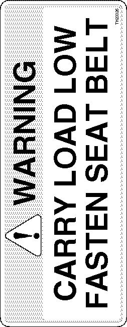

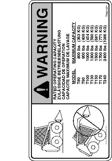

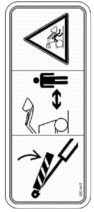
67 5.3 DECALS #35886 #39196 #23334 #32275 #25460 #37060 #39192 EXIT SORTIE AUSGANG SALIDA #36841 #23326 #41066 #36598 #37059 #41045 #42107 #43791 #35885 #


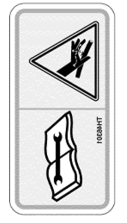

68 5.3 DECALS #38044 #38043 #23312 #23308 #41064 #39192 #23307 #37010 #39191 #23321 #23310 #43776 #23325 #


69 5.3 DECALS #41065 #47264 #44615 #47264 #
T245 HDK. Skid Steer Loader. Owner s and Operator s Manual
 T245 HDK Skid Steer Loader Owner s and Operator s Manual PUBLICATION NO. 47640 August, 2001 THOMAS EQUIPMENT LIABILITY WARRANTY THE WARRANTY IS THE ONLY OBLIGATION OF THOMAS OR A THOMAS DEALER TO THE PURCHASER
T105. Skid Steer Loader. Owner s and Operator s Manual
 T105 Skid Steer Loader Owner s and Operator s Manual PUBLICATION NO. 47639 September, 2001 THOMAS EQUIPMENT LIABILITY WARRANTY THE WARRANTY IS THE ONLY OBLIGATION OF THOMAS OR A THOMAS DEALER TO THE PURCHASER
Pro Tough Owner s and Operator s Manual
 Pro Tough 2200 Owner s and Operator s Manual PUBLICATION NO. 48241, MAY 2002 THOMAS EQUIPMENT LIABILITY WARRANTY THE WARRANTY IS THE ONLY OBLIGATION OF THOMAS OR A THOMAS DEALER TO THE PURCHASER OR ANYONE
35DT. Mini-Skid Loader
 35DT Mini-Skid Loader Owner s, Operator s and Parts Manual Publication Number - 52597 July, 2005 THOMAS EQUIPMENT LIABILITY WARRANTY THE WARRANTY IS THE ONLY OBLIGATION OF THOMAS OR A THOMAS DEALER TO
OPERATORS MANUAL SAFETY & WARRANTY SECTION
 OPERATORS MANUAL SAFETY & WARRANTY SECTION KMW Ltd. 198 N. Hwy 281 Great Bend, Kansas 67530 800 445-7388 Fax 620 793-6737 ïïïkâãïäç~çéêëkåçã SAFETY FIRST This symbol, the industry s Safety Alert Symbol,
Walker Loader Bucket OPERATOR S AND PARTS MANUAL
 Walker Loader Bucket OPERATOR S AND PARTS MANUAL Please Read and Save These Instructions For Safety, Read all Safety and Operation Instructions Prior To Operating Machine P/N 6690 TABLE OF CONTENTS Introduction
Talet Equipment International Ltd. Sand Kicker
 Talet Equipment International Ltd. Sand Kicker Parts & Operators Manual P.O. Box 35 Strathmore AB Canada TP K3 www.taletattachments.com sales@taletattachments.com Toll Free -888-37-5878 Fax -403-934-304
Trench Filler for Compact Utility Loaders
 Form No. 3353-608 Rev A Trench Filler for Compact Utility Loaders Model No. 22472 260000001 and Up Operator s Manual Register your product at www.toro.com Original Instructions (EN) Contents Page Introduction................................
Begin Program: Welcome everyone and introduce yourself, speaker(s) and/or interpreter if one is present/necessary. Feel free to include your name/prog
 and/or interpreter if one is present/necessary. Feel free to include your name/prog") Begin Program: Welcome everyone and introduce yourself, speaker(s) and/or interpreter if one is present/necessary. Feel free to include your name/program name on the title slide for purposes of personalization.
Begin Program: Welcome everyone and introduce yourself, speaker(s) and/or interpreter if one is present/necessary. Feel free to include your name/program name on the title slide for purposes of personalization.
Backhoe for Dingo Compact Utility Loaders
 Form No. 50-5 Backhoe for Dingo Compact Utility Loaders Model No. 60 000000 & Up Operator s Manual Original Instructions (EN/GB) Contents Page Introduction................................. Safety......................................
WARNING this attachments capacity changes depending on the Skid Steer Loader it is hooked up to. CAPACITY AT 24 LOAD CENTER
 SKID STEER FORKLIFT ATTACHMENT Any piece of equipment can be dangerous if not operated properly. YOU are responsible for the safe operation of this equipment. The operator must carefully read and follow
Boring Unit Sitework Systems Attachment
 FORM NO. 6 Boring Unit Sitework Systems Attachment Model No. 0 89000 & Up Operator s Manual English (CE) Contents Page Introduction................................. Safety......................................
OPERATOR S AND PARTS MANUAL PALLET FORKS. Part Number: MODEL NUMBER: Rev. 4
 OPERATOR S AND PARTS MANUAL PALLET FORKS SERIAL NUMBER: Manual Number: OM642 Part Number: 75542 MODEL NUMBER: Rev. 4 800-456-7100 I www.paladinlcg.com 503 Gay Street, Delhi, IA 52223, United States of
Backhoe for Compact Utility Loaders
 Form No. 54-4 Rev A Backhoe for Compact Utility Loaders Model No. 6 6000000 and Up Operator s Manual Register your product at www.toro.com. Original Instructions (EN) Contents Page Introduction.................................
Road Service Quick Reference Guide 2016 Lincoln MKZ / MKZ Hybrid. Quality and Education Services AAA Automotive 1000 AAA Drive Heathrow, FL 32746
 Road Service Quick Reference Guide 2016 Lincoln MKZ / MKZ Hybrid Quality and Education Services AAA Automotive 1000 AAA Drive Heathrow, FL 32746 December 12, 2015 Index Towing, Loading and Transporting
610 BUSHEL MANURE SPREADER
 610 BUSHEL MANURE SPREADER RODA MANUFACTURING 1008 LOCUST ST. HULL, IA. 51239 Art s-way Manufacturing 712-439-2366 Co., Inc. Hwy 9 West - PO Box 288 WWW.RODAMFG.COM Armstrong, IA. 50514 U.S.A 2 INTRODUCTION
Wind and Temperature Tip Over Hazard Do not add notice boards or similar
 Lift & Work Platform Safety Information Safety Information: Boom Lifts Safety Information: Scissor Lifts Safety Information: Boom Lifts Power Lines Electrocution Hazard Maintain safe clearance from Electrical
EZ Hauler 2500 Training & Procedure Manual
 EZ Hauler 2500 Training & Procedure Manual Load Capacity One of the most important considerations when operating this machine is the Load Capacity of the EZ Hauler 2500 s boom. The maximum weight capacity
Mulcher Operators Manual
 Mulcher Operators Manual Skid Pro Attachments PO Box 982 Alexandria, MN 56308 October 2015 1 2 Contents 1. Introduction And Warranty... 4 1.1 Introduction... 4 1.2 Warranty... 4 2. Component Identification...
MK AUGERS POWER SWING KIT ASSEMBLY & OPERATION MANUAL
 MK AUGERS POWER SWING KIT ASSEMBLY & OPERATION MANUAL Read this manual before using product. Failure to follow instructions and safety precautions can result in serious injury, death, or property damage.
BUCKET SWEEPER OPERATORS & PARTS MANUAL 2852 & 3174 SERIES
 OM628 BUCKET SWEEPER OPERATORS & PARTS MANUAL 2852 & 3174 SERIES MODEL 12002-5 FOOT WIDE X 24 INCH DIAMETER (SKID-STEER) MODEL 12004-6 FOOT WIDE X 24 INCH DIAMETER (SKID-STEER) MODEL 12017-6 FOOT WIDE
before serial number 2214
 before serial number 2214 Contents Page Safety Rules... 3 Pre-operational & Safety Inspection... 4 Operating Instructions... 6 Transport... 12 Maintenance & Routine Service... 12 Specifications... 14 SAFETY
Mini Skid Steer Training
 Safe Operating Practices Mini Skid Steer Training This product is capable of amputating hands and feet. Always follow all safety instructions to avoid serious injury or death. Engine exhaust contains carbon
R T SERIES ROTARY TILLER
 R T SERIES ROTARY TILLER Operating and Maintenance Manual TABLE OF CONTENTS 1. PRODUCT WARRANTY. 3 2. CHECKLIST Dealer s File Copy. 4 Customer s File Copy.. 5 3. INTRODUCTION 6 4. SPECIFICATIONS.. 7 5.
HydroTote Trailer Hydroject Aerator
 Form No. 3355 89 Rev. C HydroTote Trailer Hydroject Aerator Model No. 09833 Serial No. 6000000 and Up Operator s Manual English (EN, GB) Contents Page Introduction................................. Safety......................................
Section 4.3. Machine Operation - Operating Procedures. Before Starting the Engine: General Pre-Start Inspection
 Section 4.3 Machine Operation - Operating Procedures Before Starting the Engine: General Pre-Start Inspection... 4.3.2 Engine Starting Procedure... 4.3.2 Cold Weather Start-Up... 4.3.3 Engine Shutdown
John Deere. MODEL: 350C Crawler Loader, Bulldozer JD-O-OMT79469
 John Deere MODEL: 350C Crawler Loader, Bulldozer THIS IS A MANUAL PRODUCED BY JENSALES INC. WITHOUT THE AUTHORIZATION OF JOHN DEERE OR IT'S SUCCESSORS. JOHN DEERE AND IT'S SUCCESSORS ARE NOT RESPONSIBLE
OPERATOR S MANUAL 7(5 & ( 8&. $5.00 P/N REV.B
 OPERATOR S MANUAL &281 2817( 7(5 %$/$1&( /,)7 7758& 8&. $5.00 P/N 901345 REV.B As a lift truck operator, you are responsible for a machine that is useful, powerful, and can be hazardous if not operated
Operating and Assembly Manual
 Model 1080 Operating and Assembly Manual Midwest Equipment Manufacturing, Inc. 5225 Serum Plant Road Thorntown, IN 46071 08-02-16 SAFETY RULES Remember, any power equipment can cause injury if operated
SHEYENNE TELE-BOOM OWNERS MANUAL OPERATOR INSTRUCTIONS PARTS BOOK
 SHEYENNE TELE-BOOM OWNERS MANUAL OPERATOR INSTRUCTIONS PARTS BOOK 701 Lenham Ave. SW PO Box 647 Cooperstown ND 58425 1-800-797-1883 701-797-2700 * 701-797-2584 Fax www.sheyennemfg.com TABLE OF CONTENTS
Illustrated Parts Manual
 Illustrated Parts Manual Models 522D LoPro 524D LoPro S/N 0900 P/N - 948-403 Revised July 6, 2007 INTRODUCTION Table of Contents SECTION INTRODUCTION Table of Contents... - thru -4 Alphabetical Index...
MT55 Mini Tracked Loader A3WU A3WU /02/2010
 Copyright 2000-2010 Bobcat Europe MT55 Mini Tracked Loader A3WU 11001 A3WU 99999 15/02/2010 Dimensions (A) Angle of departure 23.3 Carry position 168 mm (C) Dump angle at maximum height 49.6 (D) Dump height
Talet Equipment International Ltd. Sanding Auger Bucket
 Talet Equipment International Ltd. Sanding Auger Bucket Parts & Operators Manual P.O. Box 35 Strathmore AB Canada TP K3 www.taletattachments.com sales@taletattachments.com Toll Free -888-37-5878 Fax -403-934-304
NET HORSEPOWER 40.3 kw rpm OPERATING WEIGHT 2940 kg 6,480 lb SK820-5 SKID STEER LOADER. Photos may include optional equipment.
 NET HORSEPOWER 40.3 kw 54 HP @ 2800 rpm OPERATING WEIGHT 2940 kg 6,480 lb SK820-5 SK 820 SKID STEER LOADER Photos may include optional equipment. SK820-5 S KID S TEER L O ADER WALK-AROUND Maximum Performance
S600/S600TX. There s nothing mini about their productivity
 Mini Skid Steers Mini Skid Steers S600/S600TX There s nothing mini about their productivity From landscape contractors to do-it-yourselfers, the Vermeer mini skid steer is a machine built for multiple
RED23305 Owner s Manual
 RED23305 Owner s Manual 5 foot, 3-Point Mounted Snow Blower 270 West Park Avenue Huron, SD 57350 866-526-5682 Serial Number: Date of Purchase: Red Devil Snow Blower See Figure 1. 1. The Red Devil Snow
ROTARY BRUSH CUTTERS THE LEADER OF THE PACK OWNER/OPERATOR SAFETY & INSTRUCTION MANUAL
 72 M-AX ROTARY BRUSH CUTTERS THE LEADER OF THE PACK OWNER/OPERATOR SAFETY & INSTRUCTION MANUAL CONTENTS Page 1. Introduction..................................2 2. Safety Instructions...........................3-4
1500 Series Roll Off Hoist. Owner s Manual (5-06)
") 1500 Series Roll Off Hoist Owner s Manual (5-06) Section 1: General Information Introduction Safety Information Warranty Information Table of Contents Section 2: Operation Operating the P.T.O. Operating
1500 Series Roll Off Hoist Owner s Manual (5-06) Section 1: General Information Introduction Safety Information Warranty Information Table of Contents Section 2: Operation Operating the P.T.O. Operating
W & A 12 ROW TOP LEVELING STACKER LEVEL BANDER
 W & A 12 ROW TOP LEVELING STACKER LEVEL BANDER NO. 3640 OPERATOR S MANUAL TO THE OWNER: Congratulations on your purchase of a new W & A Top Leveling Stacker Level Bander. Your selection is an indication
Illustrated Parts Manual
 Illustrated Parts Manual Model 544C-10 S/N 0255001 P/N - 91164001 Revised February 23, 2007 INTRODUCTION Table of Contents Original Issue 11-96 Revised 1-6-98 SECTION 1 INTRODUCTION Table of Contents...
CAUTION. Start & Stop Procedures. Section 1-2. Engine Oil Level
 Section 1-2 Start & Stop Procedures Before operating this machine, the operator must have: received operator training, a familiarity with this manual, and a complete understanding of all the procedures
Wheel Horse. 44 Snowthrower. for 5xi Lawn and Garden Tractors. Model No & Up. Operator s Manual
 FORM NO. 8 Rev A Wheel Horse Snowthrower for 5xi Lawn and Garden Tractors Model No. 7966 890050 & Up Operator s Manual IMPORTANT: Read this manual, and your tractor manual, carefully. They contain information
TABLE OF CONTENTS. Warranty Disclaimers Delivery Checklist After Sale Checklist Safety Set Up... 8
 TABLE OF CONTENTS Pickett Equipment Warranty... 2 Warranty Disclaimers... 3 Delivery Checklist... 4 After Sale Checklist... 4 Safety... 5-7 Set Up... 8 Machine Adjustments and Operation... 9 Maintenance
WHEEL LOADER OUTLINE
 Lesson 1: Lesson 2: Goals & Objectives of this Lesson - Safe Productivity. - Introduction. - Goals and Objectives. - What is a professional? Components & Control Identification - Goals and objectives of
Section 4.3. Machine Operation - Operating Procedures. Before Starting the Engine: General Pre-Start Inspection
 Section 4.3 Machine Operation - Operating Procedures Before Starting the Engine: General Pre-Start Inspection... 4.3.2 Engine Starting Procedure... 4.3.2 Cold Weather Start-Up... 4.3.3 Engine Shutdown
INSTALLATION GUIDE. Universal System for Zero Turn Mowers
 INSTALLATION GUIDE Universal System for Zero Turn Mowers Table of Contents General Information 1 Important Notice to Purchaser 2 Specifications 2 Intended Usage 2 Important Information 3 General Safety
Trencher Dingo Attachment
 Form No. 3326-453 Trencher Dingo Attachment Model No. 22459 2000000 & Up Operator s Manual English (CE) Contents Page Introduction................................ 2 Safety.....................................
Backhoe. Operation and Maintenance Manual
 Backhoe Operation and Maintenance Manual Revision Date: January 2018 Skid Pro Attachments PO Box 982 Alexandria, MN 56308 Toll Free: 877-378-4642 www.skidpro.com Contents INTRODUCTION... 2 To the Purchaser...
Talet Equipment International Ltd.
 Talet Equipment International Ltd. Postmaster and/or Slab Blaster Parts & Operators Manual P.O. Box 2351 Strathmore AB Canada T1 P 1 K3 www.taletattachments.com sales@taletattachments.com Toll Free 1-888-31
Road Service Quick Reference Guide 2016 Lincoln MKX. Quality and Education Services AAA Automotive 1000 AAA Drive Heathrow, FL 32746
 Road Service Quick Reference Guide 2016 Lincoln MKX Quality and Education Services AAA Automotive 1000 AAA Drive Heathrow, FL 32746 December 12, 2015 Index Towing, Loading and Transporting 2 Curb Weight
John Deere. MODEL: 410 Backhoe Loader JD-O-OMT66840
 John Deere MODEL: 410 Backhoe Loader THIS IS A MANUAL PRODUCED BY JENSALES INC. WITHOUT THE AUTHORIZATION OF JOHN DEERE OR IT'S SUCCESSORS. JOHN DEERE AND IT'S SUCCESSORS ARE NOT RESPONSIBLE FOR THE QUALITY
WARNING - BEFORE YOU DRIVE
 See back cover for a pre-ride checklist section 3 operation WARNING - BEFORE YOU DRIVE 1. Always perform a pre-ride inspection of the vehicle using the checklist provided on the back cover of this manual.
Operator's Manual. VC-60 & VC-60 Plus Harper Industries, Inc. 7/03 Part No
 Operator's Manual VC-60 & VC-60 Plus 2003 Harper Industries, Inc. 7/03 Part No. 970066 Thank you for purchasing a Harper/Goossen Verti-Cutter. As with all Harper/Goossen products, the Harper/Goossen Verti-Cutter
Premium Supply. Direct Push. Models PCK-3530-DP PCK DP PCK-530-DP. Operator s Manual and Installation Instructions
 Direct Push Models PCK-3530-DP PCK-3530-2DP PCK-530-DP Operator s Manual and Installation Instructions Premium Supply 2038 West Interstate 30 866-934-0777 Proud members of: and June 20, 2018 Table of Contents
Operating and Assembly Manual
 Model 455-IC/PRO/H Operating and Assembly Manual Midwest Equipment Manufacturing, Inc. 5225 Serum Plant Road Thorntown, IN 46071 03-08-12 SAFETY RULES Remember, any power equipment can cause injury if
Model 452-DIC/DH. Operating and Assembly Manual
 . Model 452-DIC/DH Operating and Assembly Manual Palmor Products Inc. 5225 Serum Plant Road Thorntown, IN 46071 02-14-12 SAFETY RULES Remember, any power equipment can cause injury if operated improperly
NET HORSEPOWER 62.6 kw rpm OPERATING WEIGHT 4330 kg 9,546 lb CK30-1 COMPACT TRACK LOADER. Photos may include optional equipment.
 NET HORSEPOWER 62.6 kw 84 HP @ 2500 rpm OPERATING WEIGHT 4330 kg 9,546 lb CK30-1 CK 30 COMPACT TRACK LOADER Photos may include optional equipment. CK30-1 C OMPACT T RACK L OADER WALK-AROUND Easy to use
Commander 15i Container and Pallet Loader. Property of American Airlines
 Commander 15i Container and Pallet Loader Section 2. Operation BEFORE ATTEMPTING TO OPERATE OR MAINTAIN THE VEHICLE, COMPLETELY READ AND UNDERSTAND THE OPERATION AND MAINTENANCE MANUAL, INCLUDING ALL DANGER,,
LARGE FRAME SKID-STEER LOADERS S220 S250 S300 S330
 LARGE FRAME SKID-STEER LOADERS S220 S250 S300 S330 Large Frame Skid-Steer Loaders Bobcat Large Frame Skid-Steer Loaders Name your task Bobcat large frame skid-steer loaders cut em down to size. These rugged
Chapter 1 Safety and Operation
 Chapter 1 Safety and Operation General The importance of safe operation cannot be over emphasized. Carelessness and neglect on the part of operators, job supervisors and planners, rigging personnel, and
MODEL HD99 HYDRAULIC ONE MAN TOWABLE EARTHDRILL
 DO NOT THROW AWAY IMPORTANT MANUAL MODEL HD99 HYDRAULIC ONE MAN TOWABLE EARTHDRILL Operators Manual GROUND HOG, INC. P.O.BOX 290 San Bernardino, CA. 92402 Phone (909) 478-5700 Fax (909) 478-5710 E-mail:
Operating and Assembly Manual
 Model 455-IC/PRO/H Operating and Assembly Manual Palmor Products Inc. 5225 Serum Plant Road Thorntown, IN 46071 03-08-12 SAFETY RULES Remember, any power equipment can cause injury if operated improperly
ROTARY TILLER. Operation, Service & Parts Manual For "AS" Series. FORM: ASTillerBook.QXD
 ROTARY TILLER Operation, Service & Parts Manual For "AS" Series FORM: ASTillerBook.QXD April 2002 TABLE OF CONTENTS Preparation......................................1 Assembly Instructions.............................2
Towing and Road Service Guide For The 2010 Lexus HS250H. Quality and Education Services AAA Automotive 1000 AAA Drive Heathrow, FL 32746
 Towing and Road Service Guide For The 2010 Lexus HS250H Quality and Education Services AAA Automotive 1000 AAA Drive Heathrow, FL 32746 October 7, 2009 Index General Vehicle Information Major Component
Premium Supply. Tilt Deck. Models PCK-TD PCK-PTD CTD-310-K. Operator s Manual and Installation Instructions
 Tilt Deck Models PCK-TD PCK-PTD CTD-310-K Operator s Manual and Installation Instructions Premium Supply 2038 West Interstate 30 866-934-0777 Proud members of: and April 20, 2018 Table of Contents Introduction...
753 Skid-Steer Loader
 Copyright 2003 Bobcat Europe 27/05/2008 Dimensions 753 Skid-Steer Loader Angle of departure... 26 Carry position... 224 mm Dump angle at maximum height... 40 Dump height with standard bucket... 2148 mm
301.5, 301.6, Mini Hydraulic Excavator
 301.5, 301.6, 301.8 Mini Hydraulic Excavator 301.5 301.6 301.8 Cat 3003 Naturally Aspirated Diesel Engine Flywheel Power 13 kw 17.4 hp 13 kw 17.4 hp 13 kw 17.4 hp Operating Weight With canopy 1616 kg 3563
Operating and Assembly Manual
 Model 380/385-IC/385-LH Operating and Assembly Manual Midwest Equipment Manufacturing, Inc. 5225 Serum Plant Road Thorntown, IN 46071 2-0916 SAFETY RULES Remember, any power equipment can cause injury
SAFETY AND OPERATION REQUIREMENTS CHART
 OPERATION, MAINTENANCE and SAFETY MANUAL MB16 and MTB16 Scoot-Crete Power Buggies IMPORTANT MACHINE SERVICE NOTES This manual covers the safety, operation and adjustment procedures for the Miller Scoot-Crete
Owner s Manual. Instructions for Assembly, Testing, Operation, and Servicing. Trailer Kit: High speed upgrade kit used with Item# WARNING
 M268176D.1 ITEM NUMBER: 268176 SERIAL NUMBER: Owner s Manual Instructions for Assembly, Testing, Operation, and Servicing Trailer Kit: High speed upgrade kit used with Item# 268175 WARNING READ and UNDERSTAND
User Manual Armadillo 9X Sweeper Models: 9X & 9XCE
 User Manual Armadillo 9X Sweeper Models: 9X & 9XCE PowerBoss, Minuteman International, Inc. A Member of the Hako Group #4100033 Rev. D 07/15 Page 1 PREFACE PREFACE Thank you for your purchase of the new
Tree Forks Sitework Systems Attachment
 Form No. 3323-274 Tree Forks Sitework Systems Attachment Model No. 22438 890001 & Up Operator s Manual English (CE) Contents Page Introduction................................. 2 Safety......................................
HORTICULTURE EQUIPMENT & SERVICES
 HORTICULTURE EQUIPMENT & SERVICES OPERATOR S MANUAL PEAT BALE PROCESSOR Model Number: LH00 Serial Number: 30000 & UP Contents Introduction Page Safety Safety 2 Safety Decal Instructions 2 Specifications
APCO ASR-400/450 SEWAGE AIR RELEASE VALVES
 APCO ASR-400/450 SEWAGE AIR RELEASE VALVES Instruction D12005 December 2012 Instructions These instructions provide installation, operation and maintenance information for the APCO ASR- 400/450 Sewage
Road Service Quick Reference Guide 2016 Lincoln MKT. Quality and Education Services AAA Automotive 1000 AAA Drive Heathrow, FL 32746
 Road Service Quick Reference Guide 2016 Lincoln MKT Quality and Education Services AAA Automotive 1000 AAA Drive Heathrow, FL 32746 December 12, 2015 Index Towing, Loading and Transporting 2 Curb Weight
ASSEMBLY INSTRUCTIONS
 CONTENTS ASSEMBLY INSTRUCTIONS... 1 TO THE DEALER... 1 SAFETY... 1 UNPACKING AND CHECKING PARTS... 2 Unpacking Wooden Crate...2 Checking Parts...3 TRACTOR PREPARATION... 4 ASSEMBLY... 4 Boom Assembly...4
Towing and Road Service Guide For The Lexus ES300h. Quality and Education Services AAA Automotive 1000 AAA Drive Heathrow, FL 32746
 Towing and Road Service Guide For The Lexus ES300h Quality and Education Services AAA Automotive 1000 AAA Drive Heathrow, FL 32746 September 7, 2012 1 Index General Vehicle Information Major Component
LEWIS WINDROWER OWNER / OPERATOR MANUAL
 LEWIS WINDROWER OWNER / OPERATOR MANUAL MODEL # WR-1 WINDROWER Manufactured by: LEWIS BROTHERS MANUFACTURING, INC. Post Office Box 146 Baxley, GA 31513 Tel: (912) 367-4651 Fax: (912) 367-3958 2-21-14 1
Towing and Road Service Guide For Lexus LS 600h L. Quality and Education Services AAA Automotive 1000 AAA Drive Heathrow, FL 32746
 Towing and Road Service Guide For Lexus LS 600h L Quality and Education Services AAA Automotive 1000 AAA Drive Heathrow, FL 32746 June 15, 2007 Index General Towing Information Special Precautions 3 Hybrid
Towing and Road Service Guide For Lexus GS 300 and GS 430. Quality and Education Services AAA Automotive 1000 AAA Drive Heathrow, FL 32746
 Towing and Road Service Guide For Lexus GS 300 and GS 430 Quality and Education Services AAA Automotive 1000 AAA Drive Heathrow, FL 32746 April 12, 2005 Index Equipment availability 3 General Towing Information
General Information - Inspection, Delivery, Service and Warranty Forms. Delivery and Inspection Information
 Section 1.1 General Information - Inspection, Delivery, Service and Warranty Forms Delivery and Inspection Information... 1.3.2 Pre-Delivery Inspection Form... 1.3.3 Delivery Report... 1.3.5 100-200 Hr
Premium Supply. Tilt Deck. Models PCK-TD PCK-PTD. Operator s Manual and Installation Instructions
 Tilt Deck Models PCK-TD PCK-PTD Operator s Manual and Installation Instructions Premium Supply 2038 West Interstate 30 866-934-0777 Proud members of: and June 1, 2015 Table of Contents Introduction...
Operator s Manual. Operator s Manual BC-O-742
 Bobcat Operator s Manual 742 Operator s Manual THIS IS A MANUAL PRODUCED BY JENSALES INC. WITHOUT THE AUTHORIZATION OF BOBCAT OR IT S SUCCESSORS. BOBCAT AND IT S SUCCESSORS ARE NOT RESPONSIBLE FOR THE
SKID STEER COMBO PLOW
 A DIV. OF NORTHERN STAR INDUSTRIES, INC. P.O. BOX 788 IRON MOUNTAIN, MICHIGAN 49801 SKID STEER COMBO PLOW INSTALLATION & OWNER S MANUAL TABLE OF CONTENTS SAFETY PRECAUTIONS... 2 ASSEMBLY PROCEDURE... 3
Road Service Quick Reference Guide Jaguar XF. Quality and Education Services AAA Automotive 1000 AAA Drive Heathrow, FL 32746
 Road Service Quick Reference Guide 2016-2017 Jaguar XF Quality and Education Services AAA Automotive 1000 AAA Drive Heathrow, FL 32746 March 31, 2017 Index Quick Specifications and Information 2 Start/Stop
25 BUSHEL MANURE SPREADER
 25 BUSHEL MANURE SPREADER RODA MANUFACTURING 338 MAIN ST. HULL, IA. 51239 Art s-way Manufacturing 712-439-2366 Co., Inc. Hwy 9 West - PO Box 288 WWW.RODAMFG.COM Armstrong, IA. 50514 U.S.A 2 INTRODUCTION
36 Tiller Wheel Horse Lawn and Garden Tractor Attachment
 Form No. 9 6 Rev B 6 Tiller Wheel Horse Lawn and Garden Tractor Attachment Model No. 797 890000 and Up Operator s Manual English(En) Contents Page Introduction................................ Safety.....................................
Multi-Purpose Tool Sitework Systems Attachment
 FORM NO. 22 648 Multi-Purpose Tool Sitework Systems Attachment Model No. 2242 89000 & Up Operator s Manual English (CE) Contents Page Introduction................................. 2 Safety......................................
32 quarts Transmission Allison HT 740 Automatic Fluid
 BOOK: Blue Book I SECTION: E-One Engine (SGT) Page 1 of 6 E-ONE CYCLONE TABLE OF CONTENTS SPECIFICATIONS... 2 DAILY CHECKS... 2 SAFETY CHECKS... 3 START ENGINE... 3 STOP ENGINE... 3 EMERGENCY SHUTDOWN
ROUGH TERRAIN VEHICLES
 ROUGH TERRAIN VEHICLES OPERATING SAFETY RULES AND PRACTICES Operator Responsibility Safe operation is the responsibility of the operator. The equipment can be dangerous if not used properly. The operator
Table of Contents. Technical Information Warning Statement
 Table of Contents Technical Information-----------------------------------1 Warning Statement--------------------------------------2 Read Before Riding-------------------------------------3 List of Parts-----------------------------------------------4
Pallet Fork Grapple. Operation and Maintenance Manual
 Pallet Fork Grapple Operation and Maintenance Manual Revision Date: July 2017 Skid Pro PO Box 982 Alexandria, MN 56308 Toll Free: 877-378-4642 www.skidpro.com TABLE OF CONTENTS INTRODUCTION... 2 To the
Towing and Road Service Guide For The Lexus CT200h. Quality and Education Services AAA Automotive 1000 AAA Drive Heathrow, FL 32746
 Towing and Road Service Guide For The Lexus CT200h Quality and Education Services AAA Automotive 1000 AAA Drive Heathrow, FL 32746 January 4 th, 2011 1 Index General Vehicle Information Major Component
RedGum GP160 Splitter. Owner s Manual
 RedGum GP160 Splitter Owner s Manual Product Description & Intended Purpose: This Log Splitter / Wood Splitter is an outdoor product that splits wood logs for use as fuel in a fireplace or a woodstove.
Auger Dingo Attachment
 Form No. 334-5 Auger Dingo Attachment Model No. 400 0000000 & Up Operator s Manual English (CE) Contents Page Introduction................................ Safety..................................... Safety
Mini Hydraulic Excavator
 302.5 Mini Hydraulic Excavator Cat 3013 Naturally Aspirated Diesel Engine Flywheel Power 17.1 kw 22.9 hp Operating Weight With canopy 2660 kg 5864 lb With cab 2783 kg 6135 lb 302.5 Mini Hydraulic Excavator
Road Service Quick Reference Guide 2016 Lincoln MKS. Quality and Education Services AAA Automotive 1000 AAA Drive Heathrow, FL 32746
 Road Service Quick Reference Guide 2016 Lincoln MKS Quality and Education Services AAA Automotive 1000 AAA Drive Heathrow, FL 32746 December 12, 2015 Index Towing, Loading and Transporting 2 Curb Weight
Richmond Conveyor. Hydraulic Ultimate Manual. January 2013
 Richmond Conveyor Hydraulic Ultimate Manual January 2013 Table of Contents Operators Manual Removing conveyor from truck Maintenance checklist Maintenance kit material list Safety information Index Installation
APCO CRF-100A RUBBER FLAPPER SWING CHECK VALVES
 APCO CRF-100A RUBBER FLAPPER SWING CHECK VALVES Instruction D12043 June 2016 DeZURIK Instructions These instructions provide installation, operation and maintenance information for APCO CRF-100A Rubber
3800 SERIES SINGLE HYDRAULIC LOCKING TOOLBAR
 3800 SERIES SINGLE HYDRAULIC LOCKING TOOLBAR 2565-774_REV_D 02/2018 OPERATOR S MANUAL PART IDENTIFICATION YETTER MANUFACTURING CO. FOUNDED 1930 Colchester, IL 62326-0358 Toll free: 800/447-5777 309/776-3222