67 Mustang Tilt-Away Steering Column Adjustment & Repair
|
|
|
- Joshua Ford
- 6 years ago
- Views:
Transcription


1 67 Mustang Tilt-Away Steering Column Adjustment & Repair NOTE: The following information was taken from Technical Service Bulletin #916 Dated October 21,1966
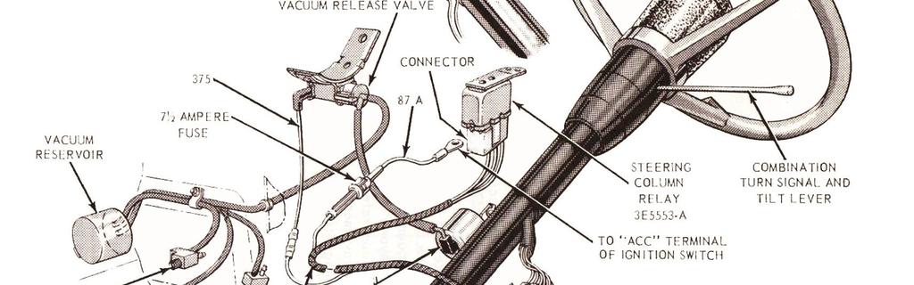
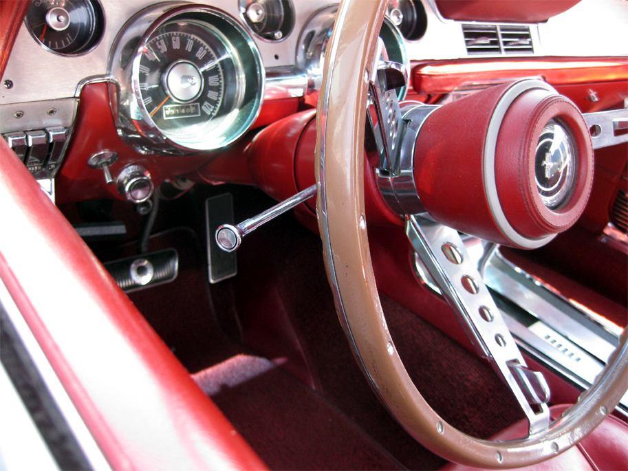
2 P a g e 2 DESCRIPTION A dual-action (tilt-away type) steering column features nine driving positions (four up and four down from a center position) and a tilt-away position that is automatically accomplished when the ignition key is turned to the OFF position and the left door is opened. This completes an electrical circuit through a switch in the left door jamb located just below the courtesy light switch and an electrically operated vacuum release valve mounted on the lower edge of the instrument panel approximately eight inches to the right of the steering column (Illus. G1476- A). The vacuum release valve is connected to a vacuum reservoir located on the right side of the dash panel in the engine compartment and to a vacuum motor located on the lower end of the steering column tube by rubber hoses. When the vacuum release valve is energized electrically, it opens a valve and allows reservoir vacuum to act on the vacuum motor diaphragm to pull the parking pawl out of the lower flange at the upper end of the column. Spring tension then moves the steering wheel upward and to the right at approximately a 45 degree angle (tilt-away position) at the steering shaft universal joint. The column will remain in the tilt-away position until the driver manually moves the column to the drive position after the left door has been closed. A starter safety switch located to the right of the vacuum motor on the steering column prevents the engine from being started while the steering wheel is in the tilt-away position. The starter safety switch is actuated by the locking pawl. A tab provided on the rod depresses the switch to open the starter motor circuit when the wheel is in the tilt position. When the steering wheel is placed in the drive position, the tab moves upward and allows the switch plunger to move upward and allows the switch plunger to move outward and close the circuit. The vacuum reservoir has a capacity STEERING to operate (cycle) the steering column for approximately three times after the engine has been shut down. VACUUM MOTOR REMOVAL AND INSTALLATION REMOVAL 1. Disconnect the vacuum hose from the lower end of the motor (Illus. CL476-A). 2, Lift the retaining clip from the lower end of the locking pawl rod, then slide the rod out of the vacuum motor push rod. Remove the retaining clip. 3, Remove the two vacuum motor attaching screws and remove the motor from the column. INSTALLATION 1. Position the vacuum motor on the column so that the retaining slot on the lower end engages the steering column tube. Install but do not tighten the two attaching screws. 2. Hold the locking pawl rod retaining clip in place on the vacuum motor rod and insert the locking pawl rod in the clip and vacuum motor rod, Snap the retaining clip into place. 3. Slide the vacuum motor as required to align the locking pawl rod and vacuum motor. Tighten the two vacuum motor attaching screws. 4. Connect the vacuum hose to the vacuum motor.

3 P a g e 3 VACUUM RELEASE YALVE REMOVAL 1. Disconnect the wire from the vacuum release valve terminal (Illus. G1476-A). 2. Disconnect the two vacuum hoses from the release valve. 3. Remove the bolt that attaches the vacuum release valve mounting bracket to the lower edge of the instrument panel. Remove the vacuum release valve and mounting bracket. INSTALLATION 1. Position the vacuum release valve on thelower edge of the instrument panel so that the mounting bracket points upward and the one connector points toward the steering column. Secure the release valve bracket with the attaching bolt. 2. Connect the wire to the terminal at the rear of the valve. 3. Connect the reservoir hose to the connector at the rear of the valve. Connect the vacuum motor hose to the connector that points toward the steering column. 4. Start the engine and check the steering column operation. STARTER SAFETY SWITCH REMOVAL 1. Disconnect the two plug in type wires from the rear of the starter safety switch located on the right side of the column (Illus. G1476-A). 2. Remove the two switch attaching screws and remove the switch and bracket. 3. Remove the switch from the bracket. INSTALLATION 1. Assemble the starter safety switch in the bracket. 2. Position the starter safety switch and bracket on the column tube and in- stall but do not tighten the screws. 3. Place the steering wheel in the drive position and slide the switch forward or back on the steering column tube to establish a clearance of inch gap between the tab on the locking pawl rod and the switch plunger, then tighten the two attaching screws. 4. Connect the two wires to the rear of the switch being careful not to disturb the position of the switch in the bracket.
 to relieve the tension from the column release lever. 3. Place the flange in a vise as shown in Illus.")
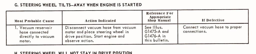
4 P a g e 4 LOCKING LEYER REMOVAL 1. Remove the upper flange and bearings as detailed on Page 3-9 of the 1967 Ford Preliminary Shop Manual. 2. Insert a 3 l,/8-inch bolt between the lower ends of the locking levers (Illus. G1459-A) to relieve the tension from the column release lever. 3. Place the flange in a vise as shown in Illus. G1459-A and remove the two retainers with a screwdriver. 4. Lift the column release lever from the flange. 5. Drive the locking lever retaining pins from the flange with a small drift. 6. Release the vise slowly to prevent the levers from flying out. 7. Remove the levers, spring caps and springs from the flange (Fig. 7 of the 1967 Ford Preliminary Manual) INSTALLATION 1. Make sure that the rubber insulators are in place in the upper flange. 2. Position the springs, spring caps and locking levers in the upper flange. 3. Place the assembly in a vise and compress the springs. Install the lever retaining pins in the upper flange. 4. Install a 3 1,/8-inch bolt between the lower ends of the locking levers as shown in Illus. G1459-A. 5. Make sure that the column release lever stop is in place in the upper flange, then position the column release lever on the flange. Install the two retainers. 6. Remove the 3 1/8-inch bolt from between the levers. 7. Install the upper flange and bearings as detailed on Page 3-9 of the 1967 Ford Preliminary Manual. PART II -- TROUBLE DIAGNOSIS TILT-AWAY STEERING COLUMN This trouble diagnosis procedure is compiled as a guide to correct problems which may occur in the tiltaway steering column, Trouble symptoms, possible causes and corrective measures are listed in the order they should be checked to eliminate the possibility of removing the steering column from the vehicle unnecessarily, or replacing serviceable parts.
5 P a g e 5
6 P a g e 6
7 P a g e 7
8 P a g e 8
DESCRIPTION AND OPERATION > CLUTCH CONTROLS
 Page 1 of 17 2004 Ford Mustang 3.9L Eng Base Service Manual: CLUTCH CONTROLS Print Date: DESCRIPTION AND OPERATION > CLUTCH CONTROLS Fig 1: Identifying Clutch Controls Components Page 2 of 17 The clutch
Steering Column. Disassembly. 1. Remove instrument panel cover and reinforcement from vehicle as described in this section.
 Page 1 of 14 Section 11-04A: Steering Column, Ranger 1997 Aerostar/Ranger Workshop Manual DISASSEMBLY AND ASSEMBLY Procedure revision date: 05/17/2000 Steering Column Disassembly 1. Remove instrument panel
TRW STEERING COLUMN MODELS CA (TILT/TELESCOPIC) AND CT (TILT ONLY) CAM REPLACEMENT KIT
 AND CT (TILT ONLY) CAM REPLACEMENT KIT") SERVICE BULLETIN (Not applicable to Mack Trucks Australia) NUMBER: SB-412-005 DATE: 6/28/02 MODEL: CX, CV, CH, CL TRW STEERING COLUMN MODELS CA (TILT/TELESCOPIC) AND CT (TILT ONLY) CAM REPLACEMENT KIT
SERVICE BULLETIN (Not applicable to Mack Trucks Australia) NUMBER: SB-412-005 DATE: 6/28/02 MODEL: CX, CV, CH, CL TRW STEERING COLUMN MODELS CA (TILT/TELESCOPIC) AND CT (TILT ONLY) CAM REPLACEMENT KIT
REMOVAL & INSTALLATION
 REMOVAL & INSTALLATION Removal 1. Center steering wheel. Disconnect negative battery cable. Remove steering coupling shield (if equipped). Disconnect steering shaft at flexible coupling or pot joint. Note
Rear seat. Rear seat, removing and installing. - Using screwdriver -2-, carefully lift headrest guides -3- out of rear backrest -1-.
 Page 1 of 19 72-57 Rear seat Rear seat, removing and installing - Using screwdriver -2-, carefully lift headrest guides -3- out of rear backrest -1-. - Detach rear seat -2- upward out of mounting -3-.
REMOVAL AND INSTALLATION Procedure revision date: 05/17/2000
 1997 Aerostar/Ranger REMOVAL AND INSTALLATION Procedure revision date: 05/17/2000 Module, Driver Side Air Bag NOTE: In general, if the air bag did not deploy in an accident, it was not needed. Complete
1999 Explorer/Mountaineer Workshop Manual
 Page 1 of 16 SECTION 211-04: Steering Column 1999 Explorer/Mountaineer Workshop Manual DISASSEMBLY AND ASSEMBLY Procedure revision date: 07/27/1998 Steering Column Automatic Transmission Disassembly WARNING:
The steering column is of a modular construction and features easy to service electrical switches.
 file://c:\tso\tsocache\vdtom_5368\svk~us~en~file=svkb4a01.htm~gen~ref.htm Page 1 of 3 Section 11-04A: Steering Column, Ranger DESCRIPTION AND OPERATION 1997 Ranger Workshop Manual Steering Column NOTE:
CRUISE CONTROL SYSTEM
 CRUISE CONTROL SYSTEM 1993 Mitsubishi Montero 1993 ACCESSORIES & EQUIPMENT Mitsubishi Cruise Control Systems Montero DESCRIPTION & OPERATION The cruise control system is electronically and vacuum controlled.
SERVICE PROCEDURES FOR CLUTCH HYDRAULIC UNITS
 SERVICE PROCEDURES FOR CLUTCH HYDRAULIC UNITS SAFETY PROCEDURES Always follow the vehicle manufacturer's recommended safety procedures in your Shop and Owners Manual. REQUIRED TOOLS Flat blade screwdriver,
CRUISE CONTROL SYSTEM
 CRUISE CONTROL SYSTEM 1992 Infiniti G20 1991-92 SAFETY EQUIPMENT Infiniti Cruise Control Systems G20, M30, Q45 DESCRIPTION & OPERATION NOTE: For system component locations, see SYSTEM COMPONENT LOCATIONS.
1989 Jeep Cherokee. STEERING COLUMN' '1989 STEERING Jeep Steering Columns STEERING COLUMN STEERING Jeep Steering Columns
 STEERING COLUMN 1989 STEERING Jeep Steering Columns DESCRIPTION All models use collapsible steering columns. All columns have integral ignition switch and locking device. Optional tilt wheel is available
Stowe Cargo Management System
 Installation Guide Stowe Cargo Management System Table of Contents 1. Pre-Installation (Page 2) a. Notes, Installation Kit contents & Tools needed 2. How to Install the Stowe Cargo Management System (Pages
Transaxle. 1. Mount the transaxle to Bench Mounted Holding Fixture T57L-500-B.
 «1997 Aspire Table of Contents» «Group 07: TRANSAXLE» «Section 07-01: Transaxle, Automatic» «DISASSEMBLY» Transaxle CAUTION: To prevent dirt from entering the transaxle, it should be disassembled and kept
Installation Guide. Stowe Cargo Management System. Table of Contents
 Installation Guide Stowe Cargo Management System Table of Contents 1. Pre-Installation (Page 2) a. Notes, Installation Kit contents & Tools needed 2. How to Install the Stowe Cargo Management System (Pages
JUNCTION BLOCK DESCRIPTION OPERATION XK 8W-97 POWER DISTRIBUTION 8W
 XK 8W-97 POWER DISTRIBUTION 8W - 97-7 JUNCTION BLOCK DESCRIPTION An electrical Junction Block(JB) is concealed beneath the driver side of the instrument panel in the passenger compartment of the vehicle.
Dismantling and assembling transmission
 27-640 Dismantling and assembling transmission Operation number of the operation texts and work units or standard texts and flat rates: 27-4010 P27-5367-61 Control pressure cable (98) Slacken, remove and
M GT 2005 up Mustang ENGINE START Push-Button INSTRUCTION SHEET
 Please contact the Ford Racing Techline for the most current instruction information @ (800) FORD-788!!! PLEASE READ THE FOLLOWING INSTRUCTIONS CAREFULLY PRIOR TO INSTALLATION!!! OVERVIEW: The following
1995 Town Car/Crown Victoria/Grand Marquis
 Page 1 of 23 Section 11-04: Steering Column DISASSEMBLY AND ASSEMBLY 1995 Town Car, Crown Victoria, Grand Marquis Workshop Manual Steering Column Disassembly 1. Disconnect battery ground cable (14301)
F - BASIC TESTING Toyota Celica INTRODUCTION PRELIMINARY INSPECTION & ADJUSTMENTS VISUAL INSPECTION MECHANICAL INSPECTION
 F - BASIC TESTING 1994 Toyota Celica 1994 ENGINE PERFORMANCE Toyota 4-Cylinder Basic Diagnostic Procedures Celica INTRODUCTION The following diagnostic steps will help prevent overlooking a simple problem.
INSTALLATION INSTRUCTIONS
 INSTALLATION INSTRUCTIONS Accessory Application Publications No. All 12035 SYSTEM 2012 RIDGELINE Issue Date NOV 2011 PARTS LIST Security System Attachment Kit: P/N 08E55-SJC-101 Flange bolt Unit bracket
1991 Mazda MX-5 Miata. STARTER - DIRECT DRIVE ELECTRICAL Mazda Starters - Direct Drive ELECTRICAL Mazda Starters - Direct Drive
 DESCRIPTION STARTER - DIRECT DRIVE 1990-92 ELECTRICAL Mazda Starters - Direct Drive Nippondenso direct drive starter is a conventional 12-volt, 4-pole, brush-type starter. The integral solenoid is attached
This file is available for free download at
 This file is available for free download at http://www.iluvmyrx7.com This file is fully text-searchable select Edit and Find and type in what you re looking for. This file is intended more for online viewing
1995 Jeep Grand Cherokee Limited. CRUISE CONTROL SYSTEM' '1995 ACCESSORIES & SAFETY EQUIPMENT Chrysler Corp. Cruise Control Systems
 TROUBLE SHOOTING NO CRUISE CONTROL WHEN SET BUTTON IS PRESSED & RELEASED Check for: blown fuse, no vacuum at servo and/or defective servo, disconnected speed control cable, brakelight switch out of adjustment,
CRUISE CONTROL SYSTEM
 CRUISE CONTROL SYSTEM 1990 Nissan 240SX 1990 ACCESSORIES & EQUIPMENT Nissan Cruise Control Systems Axxess, Maxima, Pathfinder, Pickup, Stanza, 240SX, 300ZX DESCRIPTION & OPERATION NOTE: For system component
CRUISE MASTER X-A-B-C-E SERIES
 CRUISE MASTER - X-A-B-C-E SERIES 9E- 1 CRUISE MASTER X-A-B-C-E SERIES WARNING: IF EQUIPPED WITH AIR CUSHION RESTRAINT SYSTEM, DO NOT ATTEMPT ANY ADJUSTMENT, REPAIR OR REMOVAL OF ANY ACCESSORY OR COMPONENTS
HORN OPERATION DIAGNOSIS MOST GM VEHICLES 1967 AND UP
 Revised: 27OC2010 HORN OPERATION DIAGNOSIS MOST GM VEHICLES 1967 AND UP All General Motors vehicles (from the 60s through the 80s) have a horn or horns that operate on the same basic principle. When you
GENUINE PARTS INSTALLATION INSTRUCTIONS
 GENUINE PARTS INSTALLATION INSTRUCTIONS 1 DESCRIPTION: 2 APPLICATION: 3 PART NUMBER(S) REQUIRED FOR INSTALLATION: Fog Lamp Kit Rogue w/ AL 999F1 G2000 (Fog Lamp Kit) 4 KIT CONTENTS: Item Qty. Part Description
STEERING COLUMN - TILT
 STEERING COLUMN - TILT 1993 Toyota Celica 1993 STEERING Toyota - Steering Columns - Tilt Wheel Celica DESCRIPTION & OPERATION Tilt steering wheels incorporate an upper steering shaft, attached by a "U"
1994 Ford Pickup F250. STEERING COLUMN - EXCEPT STRIPPED CHASSIS 1994 STEERING Ford Motor Co. - Steering Columns - Except Stripped Chassis
 STEERING COLUMN - EXCEPT STRIPPED CHASSIS 1994 STEERING Ford Motor Co. - Steering Columns - Except DESCRIPTION NOTE: Unless otherwise specified, references to Pickup include the F350 Super Duty commercial
BRAKES. Section III REAR AXLE DATA AND SPECIFICATIONS HAND BRAKE CHRYSLER SERVICE MANUAL BRAKES 17
 BRAKES 17 There is no basic design change in the rear axle and sure grip differential except the larger diameter pinion shaft is now used on all models for 1959. The Service Procedures will remain the
PRELIMINARY INSPECTION & ADJUSTMENTS
 PRELIMINARY INSPECTION & ADJUSTMENTS VISUAL INSPECTION Most driveability problems in the engine control system result from faulty wiring, poor electrical connections or leaking air and vacuum hose connections.
J2 Remove sound insulation/knee guard 1 and side panel 2 on center console
 J1 Preparations Drive car forward on a level surface so that wheels are straight. Disconnect battery negative lead. Turn ignition key to position 1 so that steering lock is off. J2 Remove sound insulation/knee
GENUINE PARTS INSTALLATION INSTRUCTIONS
 GENUINE PARTS INSTALLATION INSTRUCTIONS 1 DESCRIPTION: 2 APPLICATION: 3 PART NUMBER(S) REQUIRED FOR INSTALLATION: Fog Lamp Kit (AL) Rogue (SV) 999F1 G2000 (Fog Lamp Kit) 4 KIT CONTENTS: Item Qty. Part
1994 Mazda B4000 SE. CRUISE CONTROL SYSTEM 1994 ACCESSORIES/SAFETY EQUIPMENT Mazda Cruise Control System
 DESCRIPTION Cruise control system consists of control switches located on steering wheel, servo throttle actuator assembly, speed sensor mounted on transmission (transfer case on 4WD), clutch switch (M/T),
INTEGRAL POWER STEERING GEAR FORD Applies to F-100 F-350 (4X2), F-150 F-250 (4X4) And Bronco
, F-150 F-250 (4X4) And Bronco") Rockcrawler Steering Shop Manual page1 The following is from the Ford 1978 Truck Shop Manual, Volume 1 Chassis. It is provided here as a courtesy to classic Ford owners who would like to perform their
Rockcrawler Steering Shop Manual page1 The following is from the Ford 1978 Truck Shop Manual, Volume 1 Chassis. It is provided here as a courtesy to classic Ford owners who would like to perform their
Quick Start Guide Compact 24 LET ( s/n & up)
") Quick Start Guide Compact 24 LET (920022 s/n 000101 & up) Step 1: Assemble Handlebar Step 2: Install Trigger Cable Assembly Step 3: Install Discharge Chute Step 4: Install Discharge Chute Crank Step 5:
Quick Start Guide Compact 24 LET (920022 s/n 000101 & up) Step 1: Assemble Handlebar Step 2: Install Trigger Cable Assembly Step 3: Install Discharge Chute Step 4: Install Discharge Chute Crank Step 5:
CRUISE CONTROL SYSTEM
 CRUISE CONTROL SYSTEM 1994 Volvo 960 1994 ACCESSORIES/SAFETY EQUIPMENT Cruise Control System 960 DESCRIPTION & OPERATION MAIN SWITCH Cruise control main switch is located at end of directional signal lever.
ANTI-LOCK BRAKE SYSTEM
 ANTI-LOCK BRAKE SYSTEM 1992 Infiniti G20 1990-92 BRAKES Infiniti Anti-Lock Brake System Infiniti; G20, M30, Q45 DESCRIPTION & OPERATION The Anti-Lock Brake System (ABS) prevents wheel lock-up during abrupt
Auto Tilt Away Steering Column
 SR19 Auto Tilt Away Steering Column COMPONENTS SR20 STEERING DISASSEMBLY OF STEERING COLUMN 1. REMOVE IGNITION KEY CYLINDER ILLUMINATION 2. REMOVE INTERMEDIATE SHAFT 3, REMOVE WIRING HARNESS CLAMP 4. (USA)
1992 Clutch. Eclipse, Expo/Expo LRV, Galant, Mirage, Precis, 3000GT
 Article Text ARTICLE BEGINNING 1992 Clutch Eclipse, Expo/Expo LRV, Galant, Mirage, Precis, 3000GT DESCRIPTION All clutches are single disc type. Pressure plate assembly uses a diaphragm spring to engage
1997 Thunderbird/Cougar
 Page 1 of 7 Section 11-04: Steering Column 1997 Thunderbird/Cougar Workshop Manual DISASSEMBLY AND ASSEMBLY Procedure revision date: 05/16/2000 Steering Column Disassembly CAUTION: Do not remove the steering
2005 BMW 545i. Crank engine at central bolt in direction of rotation until drive belt is fully guided in belt pulley.
 Fig. 235: Installing Special Tool On Drive Belt Crank engine at central bolt in direction of rotation until drive belt is fully guided in belt pulley. Remove special tool 64 1 040. Installation: Check
CLUTCH - HIGH EFFORT - DASH CRACKED IN CLUTCH MASTER CYLINDER AREA-VEHICLES BUILT BEFORE 6/15/90
 Page 1 of 17 HIGH CLUTCH EFFORT/CLUTCH FLUID LEAK - CRACKED MOUNT TECHNICAL SERVICE BULLETIN Reference Number(s): 90-16-7, Date of Issue: August 1, 1990 Related Ref Number(s): 90-16-7 ARTICLE BEGINNING
2001 Toyota MR ENGINES' '1.8L 4-Cylinder
 TIMING CHAIN Removal 1. Disconnect negative battery cable. Drain cooling system. On Corolla, remove windshield washer fluid reservoir. On Celica, remove upper front fender apron seal and upper radiator
ContiTech: Expert Tips for Changing Timing Belts
 ContiTech: Expert Tips for Changing Timing Belts Detailed instructions for a CT1015 WP1 and CT1018K1 in an Audi A4 (B6) 2.5-liter V6 TDI with engine code AKE MY 2001 ContiTech shows how to avoid errors
DESCRIPTION Chevrolet Chevy Van 5.7L Eng G20. Service Manual: FUEL INJECTION SYSTEM - TBI
 Service Manual: FUEL INJECTION SYSTEM - TBI DESCRIPTION 1989 Chevrolet Chevy Van 5.7L Eng G20 The throttle body fuel injection system consists of 7 major sub-assemblies: fuel supply system, throttle body
STARTING SYSTEMS 8B - 1 STARTING SYSTEMS CONTENTS
 TJ STARTING SYSTEMS 8B - 1 STARTING SYSTEMS CONTENTS page DESCRIPTION AND OPERATION STARTER MOTOR... 2 STARTER RELAY... 3 STARTING SYSTEM... 1 DIAGNOSIS AND TESTING STARTER MOTOR... 8 STARTER MOTOR NOISE
1995 Mercury Grand Marquis GS
 AIR BAG SYSTEM CAUTION: Read the following safety precautions BEFORE servicing steering columns on vehicles equipped with air bag restraint system. ALWAYS wear safety glasses when servicing vehicle with
1997 Mazda MX-5 Miata. STARTER - DIRECT DRIVE 1997 STARTING & CHARGING SYSTEMS Mazda - Starters - Direct Drive
 STARTER - DIRECT DRIVE 1997 STARTING & CHARGING SYSTEMS Mazda - Starters - Direct Drive DESCRIPTION & OPERATION Direct drive starter is a conventional 12-volt, 4-pole, brush-type starter. The integral
SUBJECT: While In Bi-level Mode, Air Flow From Panel Vents Is Less Than That Of The Floor Vents
 NUMBER: GROUP: 24-20-99 Rev. A Heating & A/C DATE: Dec. 17, 1999 This bulletin is supplied as technical information only and is not an authorization for repair. No part of this publication may be reproduced,
DESCRIPTION FUEL AND VACUUM PUMP REMOVE AND REPLACE FUEL PUMP-OVERHAUL 6B PONTIAC SHOP MANUAL. S. Install battery and connect cables.
 6B-74 1955 PONTIAC SHOP MANUAL DESCRIPTION FUEL AND VACUUM PUMP All models are equipped with a combination fueland double acting vacuum pump operated by an eccentric bolted to the front end of the engine
1994 Mazda MX-5 Miata. STARTER - DIRECT DRIVE 1994 ELECTRICAL Mazda Starter - Direct Drive
 DESCRIPTION STARTER - DIRECT DRIVE 1994 ELECTRICAL Mazda Starter - Direct Drive Nippondenso direct drive starter is a conventional 12-volt, 4-pole, brush-type starter. The integral solenoid is attached
Z-Gate Universal Shifter
 Installation Instructions Z-Gate Universal Shifter Fits: GM, Ford, Lincoln and Chrysler Transmissions See Application Guide for Specific Applications Part #80681 Rev 06/01/2018 WORK SAFELY! For maximum
2003 Dodge Dakota ENGINE PERFORMANCE Removal & Installation - Dakota
 FUEL LINE DISCONNECT FITTINGS NOTE: Fuel lines may contain single tab, dual tab or plastic retainer ring disconnect fitting. Determine type of disconnect fitting used and use proper procedure for proper
REMOVAL AND INSTALLATION
 501-12-1 Instrument Panel and Console 501-12-1 REMOVAL AND INSTALLATION Instrument Panel Removal CAUTION: Electronic modules are sensitive to static electrical charges. If exposed to these charges, damage
Quick Start Guide Deluxe 30 ( s/n 101 & up)
") Quick Start Guide Deluxe 30 (921032 s/n 101 & up) Step 1: Assemble Handlebars Step 2: Connect Headlight Wire Harness Step 3: Install Discharge Chute Step 4: Install Discharge Chute Crank Step 5: Install
Quick Start Guide Deluxe 30 (921032 s/n 101 & up) Step 1: Assemble Handlebars Step 2: Connect Headlight Wire Harness Step 3: Install Discharge Chute Step 4: Install Discharge Chute Crank Step 5: Install
OVERHEAD CONSOLE SYSTEMS
 DN OVERHEAD CONSOLE SYSTEMS 8V - 1 OVERHEAD CONSOLE SYSTEMS TABLE OF CONTENTS page AND OPERATION OVERHEAD CONSOLE SYSTEM...1 OVERHEAD CONSOLE...1 COMPASS MINI-TRIP COMPUTER....2 OVERHEAD CONSOLE READING
10/01/00 1er octobre Recall - Park Brake Control Modification
 00S37 10/01/00 1er octobre 2000 - - Dealer Letter - October 2000 - Dealer Letter - November 2000 - Attachment I - Administrative Information - Attachment II - Labor and Parts Information - Attachment III
CAUTION: Do not compress the ratchet assembly. This will damage the ratchet assembly.
 Installation Engines with ratcheting timing chain tensioners 1. CAUTION: Timing chain procedure must be followed exactly or damage to valves and pistons will result. CAUTION: Do not compress the ratchet
OnGuard System Retrofit Kit Installation Instructions
 Issued 05-13 Technical Bulletin OnGuard System Retrofit Kit Installation Instructions Issued 1 Technical 05-13 Bulletin Hazard Alert Messages Read and observe all Warning and Caution hazard alert messages
 www.clubsuprafrance.com CLUTCH 1996 Toyota Supra 1995-96 Clutch Supra DESCRIPTION The single, dry-type disc clutch uses a hydraulicallyoperated master cylinder with a clutch release cylinder mounted on
IN-VEHICLE REPAIR. Timing Drive Components. Removal. 3. Disconnect the eight ignition coil electrical connectors.
 303-01A-1 IN-VEHICLE REPAIR Timing Drive Components 303-01A-1 Special Tool(s) Compressor, Valve Spring 303-581 (T97T-6565-A) Holding Tool, Crankshaft 303-448 (T93P-6303-A) 3. Disconnect the eight ignition
NOTE: PERFORM THE PARKING BRAKE CABLE INSPECTION ON BOTH RIGHT AND LEFT REAR PARKING BRAKE CABLES.
 NUMBER: 05-002-01 GROUP: Brakes DATE: Mar. 9, 2001 This bulletin is supplied as technical information only and is not an authorization for repair. No part of this publication may be reproduced, stored
1991 Volkswagen Vanagon Syncro
 corner of radiator. See Fig. 1. Fig. 1: Bleeding Cooling System 2. Open bleeder valve in engine compartment (turn counterclockwise). See Fig. 1. Fill expansion tank until full. Start and run engine at
Models Affected: Certain 2015 & 2016 All American Front Engine and Vision Buses Equipped with Hydraulic Brakes ISSUE _ CORRECTIVE ACTION _
 R E C A L L C A M P A I G N -- R 1 4 X R ---- Models Affected: Certain 2015 & 2016 All American Front Engine and Vision Buses Equipped with Hydraulic Brakes ISSUE _ CORRECTIVE ACTION -- -- _ The parking
REPAIR INSTRUCTIONS - ON VEHICLE
 2013 TRANSMISSION Automatic Transmission - 6T40 - Repair Instructions - On Vehicle - Orlando REPAIR INSTRUCTIONS - ON VEHICLE MANUAL SHIFT DETENT LEVER WITH SHAFT POSITION SWITCH ASSEMBLY REPLACEMENT Special
1996 Toyota Camry DX ENGINE PERFORMANCE Toyota Basic Diagnostic Procedures
 FUEL SYSTEM Basic diagnosis of fuel system should begin by checking fuel pump operation and fuel pressure. WARNING: ALWAYS release fuel pressure before disconnecting any fuel injection-related component.
1994 Mazda MX-5 Miata. STARTER - REDUCTION GEAR 1994 ELECTRICAL Mazda Starter - Reduction Gear
 DESCRIPTION STARTER - REDUCTION GEAR 1994 ELECTRICAL Mazda Starter - Reduction Gear The Nippondenso reduction gear starter is a conventional 12-volt, 4-pole, brush-type starter. The integral solenoid is
OVERVIEW: This bulletin involves correcting a sealant void between the cowl plenum lower panel and dash crossmember.
 NUMBER: 23-029-15 GROUP: Body DATE: July 21, 2015 This bulletin is supplied as technical information only and is not an authorization for repair. No part of this publication may be reproduced, stored in
Trailer Brake System Bleeding Procedure:
 Trailer Brake System Bleeding Procedure: The procedure immediately below assumes that a power bleeder will be used. Two people will be required to bleed the brakes if bleeding is to be performed conventionally
1993 ACCESSORIES & EQUIPMENT Volkswagen Cruise Control Systems. Volkswagen; Corrado SLC, EuroVan, Passat
 Article Text ARTICLE BEGINNING 1993 ACCESSORIES & EQUIPMENT Volkswagen Cruise Control Systems Volkswagen; Corrado SLC, EuroVan, Passat DESCRIPTION & OPERATION The cruise control system allows driver to
BRAKE SYSTEM Article Text 1992 Mitsubishi Mirage For a a a a a Copyright 1998 Mitchell Repair Information Company, LLC Monday, April 01, :05AM
 Article Text ARTICLE BEGINNING 1992 BRAKES Chrysler Motors/Mitsubishi - Disc & Drum Chrysler Motors: Colt, Colt 200, Colt Vista, Ram-50, Stealth, Summit, Summit Wagon; Mitsubishi: Diamante, Eclipse, Expo/Expo
P2284 REQUESTED INFORMATION. Pinpoint Test Ao: Injector Control Pressure Too High. Print Ford Pickup 6.0L Eng F250 Super Duty.
 Print 2004 Ford Pickup 6.0L Eng F250 Super Duty P2284 REQUESTED INFORMATION Pinpoint Test Ao: Injector Control Pressure Too High Introduction Signal Function The injector control pressure is determined
Master Power Brakes Disc Brake Conversion Kit Ford Mustang P/N: BM1521KA & BM1521KS
 Master Power Brakes Disc Brake Conversion Kit 67-70 Ford Mustang P/N: BM1521KA & BM1521KS BM1521KA (9 Single w/auto Trans) BM1521KS (8 Dual w/manual Trans) Thanks for your purchase of our Power Brake Conversion
Mopar 8 3/4 & 9 3/4 (Dana) Installation Instructions Rear Disc Conversion
 Installation Instructions Rear Disc Conversion") Mopar 8 3/4 & 9 3/4 (Dana) Installation Instructions Rear Disc Conversion This kit is for either Mopar 8 ¾ or Mopar 9 ¾ (Dana). This kit is designed to work with axles with either GM 5 x 4.75 Bolt Pattern
Mopar 8 3/4 & 9 3/4 (Dana) Installation Instructions Rear Disc Conversion This kit is for either Mopar 8 ¾ or Mopar 9 ¾ (Dana). This kit is designed to work with axles with either GM 5 x 4.75 Bolt Pattern
POWER DISTRIBUTION SYSTEMS
 DN POWER DISTRIBUTION SYSTEMS 8O - 1 POWER DISTRIBUTION SYSTEMS TABLE OF CONTENTS page AND POWER DISTRIBUTION SYSTEM....1 POWER DISTRIBUTION CENTER...1 GENERATOR CARTRIDGE FUSE....2 JUNCTION BLOCK...2
2000 Dodge Durango ACCESSORIES & EQUIPMENT' 'Power Windows - Dakota & Durango 2000 ACCESSORIES & EQUIPMENT. Power Windows - Dakota & Durango
 DESCRIPTION & OPERATION 2000 ACCESSORIES & EQUIPMENT Power Windows - Dakota & Durango A permanent magnet motor moves each of the power windows. A master switch on driver's door controls all windows and
Trim (general) Lower A-pillar trim, removing and installing
 Lower A-pillar trim, removing and installing") Page 1 of 16 70-72 Trim (general) Lower A-pillar trim, removing and installing - To remove, remove A-pillar bolts 4 (2x). Tightening torque: 1.5 Nm (13 in. lb) - Remove door seal -2- in area of A-pillar
Page 1 of 16 70-72 Trim (general) Lower A-pillar trim, removing and installing - To remove, remove A-pillar bolts 4 (2x). Tightening torque: 1.5 Nm (13 in. lb) - Remove door seal -2- in area of A-pillar
ANTI-LOCK BRAKE SYSTEM - REAR WHEEL
 ANTI-LOCK BRAKE SYSTEM - REAR WHEEL 1994 Nissan Pickup 1994 BRAKES Nissan - Rear Anti-Lock Pathfinder, Pickup DESCRIPTION In 2WD mode, Rear Anti-Lock Brake System (RABS) helps the driver to maintain steering
Front Door Non-Functional - Latch Replacement
 Page 1 of 6 Home Account Contact ALLDATA Log Out Help DAN GRIMWOOD DAN GRIMWOOD00002 Select Vehicle New TSBs Technician's Reference Component Search: OK 2002 Ford Truck Escape 2WD L4-122 2.0L DOHC VIN
HAND THROTTLE KIT For Workman 3000 Series
 FORM NO. 7 6 MODEL NO. 0746 INSTALLATION INSTRUCTIONS HAND THROTTLE KIT For Workman 000 Series. Position vehicle on a clean, level surface, stop engine, engage parking brake and remove key from ignition
2006 Saturn Ion ACCESSORIES & EQUIPMENT Doors - Ion
 POWER DOOR LOCK SWITCH REPLACEMENT Removal Procedure Fig. 28: View Of Power Door Lock Switch 1. Using a flat-bladed tool, pry the switch from the door trim panel enough to expose the locking tabs. 2. Press
A/C COMPRESSOR SERVICING Article Text 1991 Saab 9000 For Copyright 1997 Mitchell International Friday, October 15, :22PM
 Article Text ARTICLE BEGINNING 1991 GENERAL SERVICING Compressor Service * PLEASE READ THIS FIRST * CAUTION: When discharging air conditioning system, use only approved refrigerant recovery/recycling equipment.
STEERING COLUMN - TILT
 STEERING COLUMN - TILT 1994 Toyota Celica 1994 STEERING Toyota - Steering Column - Tilt Wheel Celica DESCRIPTION & OPERATION Tilt steering wheels incorporate a mainshaft, attached by a "U" joint to an
./#0#. 1"&." 1994 ELECTRICAL Suzuki of America Corp. - Starters. Swift
 !"" #$%!& '()!)((*(+,*)- 1994 ELECTRICAL Suzuki of America Corp. - Starters Swift Two types of starter motors are used, conventional and reduction gear. Both types of starters consist of yoke assembly,
Installation Manual For ISL98, ISL03, ISL07, ISC07
 Installation Manual For ISL98, ISL03, ISL07, ISC07 Table of Contents Section 1: Introduction... 3 Housing Identification... 3 Engine Identification... 3 Special Tools... 3 Automatic Transmissions... 3
POWER BRAKES-BENDIX GENERAL DESCRIPTION
 5-14 1955 PONTIAC SHOP MANUAL POWER BRAKES-BENDIX GENERAL DESCRIPTION The Bendix power brake unit can be identified by the die-cast hydraulic cylinder and pressed steel filler cap (Fig. 5-17). The Moraine
PRO RATCHET UNIVERSAL SHIFTER
 Installation Instructions PRO RATCHET UNIVERSAL SHIFTER Fits: GM, Ford and Chryslers w/automatic Transmission See Application Guide for Specific Vehicles Catalog # 80842 WORK SAFELY! For maximum safety,
TORCH MOUNTAIN REAR HUB SERVICE
 Industry Nine products are designed to keep you in the saddle and out of the service queue. Regular service and maintenance is simple and can be performed with basic tools readily available to the home
55-64 Full Size GM (Impala, Bel Air, etc.) This kit is for axles with a 3 3/8 spread center to center on the top two bolt holes (pictured left).
 This kit is for axles with a 3 3/8 spread center to center on the top two bolt holes (pictured left).") SUM-BK1624A Full Size GM Installation Instructions Rear Disc Conversion 55-64 Full Size GM (Impala, Bel Air, etc.) This kit is for axles with a 3 3/8 spread center to center on the top two bolt holes (pictured
SUM-BK1624A Full Size GM Installation Instructions Rear Disc Conversion 55-64 Full Size GM (Impala, Bel Air, etc.) This kit is for axles with a 3 3/8 spread center to center on the top two bolt holes (pictured
A /F/X Body Instruction Packet Rear Disc Conversion
 A /F/X Body Instruction Packet Rear Disc Conversion 64-72 A Body / 67-81 F Body / 62-74 X Body This kit is for axles with a 3 1/8 spread center to center on the top two bolt holes (pictured left). Rotor
DRIVE AXLES. Differentials & Axle Shafts - Corvette
 DESCRIPTION & OPERATION 1998-99 DRIVE AXLES Differentials & Axle Shafts - Corvette A Getrag 625 model differential is used on both the automatic and manual transmissions. Differential carrier and case
LIGHT DUTY ROLL UP DOOR
 1-800-225-6729 LIGHT DUTY ROLL UP DOOR CAUTION Use proper lifting equipment and correct lifting procedures to avoid damage or injury. MODEL 150C installation guide A rolling door is a large heavy object
INSTALLATION INSTRUCTIONS GRILLE GUARD TOYOTA TUNDRA TOYOTA SEQUOIA PART # P2067
 INSTALLATION INSTRUCTIONS GRILLE GUARD 07-14 TOYOTA TUNDRA 08-14 TOYOTA SEQUOIA PART # P2067 PARTS LIST: GRILLE GUARD 1 Grille Guard 2 10mm Cam Lever Quick Release Bolts with Special Pivot Washer 1 Driver/left
Installation Instructions AOD Transmissions 2014, 1995 B&M Racing & Performance Products
 Installation Instructions AOD Transmissions 2014, 1995 B&M Racing & Performance Products Congratulations, you have purchased the best automatic transmission available. We at B&M are proud of our products
Tilt Steering Column Instruction Sheet
 Tilt Steering Column Instruction Sheet PLEASE READ BEFORE YOU BEGIN TO INSTALL COLUMN Flaming River all new parts pledge. The best in the business and a three-year warranty. Flaming River tilt steering
Geo Prizm ( LSi) Toyota Celica 1.8L (1994)
 Toyota Celica 1.8L (1994)") Page 1 of 140 ARTICLE BEGINNING APPLICATION TRANSMISSION APPLICATIONS Application Geo Prizm (1993-94 LSi) Toyota Celica 1.6L (1993) Celica 1.8L (1994) Celica 2.2L (1993) Corolla 1.8L MR2 Paseo Transaxle
Page 1 of 140 ARTICLE BEGINNING APPLICATION TRANSMISSION APPLICATIONS Application Geo Prizm (1993-94 LSi) Toyota Celica 1.6L (1993) Celica 1.8L (1994) Celica 2.2L (1993) Corolla 1.8L MR2 Paseo Transaxle
CLUTCH 6-1 CLUTCH CONTENTS
 TJ CLUTCH 6-1 CLUTCH CONTENTS page GENERAL INFORMATION CLUTCH COMPONENTS... 1 INSTALLATION METHODS AND PARTS USAGE... 1 DESCRIPTION AND OPERATION CLUTCH OPERATION... 1 DIAGNOSIS AND TESTING DIAGNOSTIC
BRAKE SYSTEM Nissan 240SX DESCRIPTION BRAKE BLEEDING * PLEASE READ FIRST * BLEEDING PROCEDURES ADJUSTMENTS BRAKE PEDAL HEIGHT SPECS TABLE
 BRAKE SYSTEM 1990 Nissan 240SX 1990 BRAKE SYSTEMS Nissan Disc & Drum Axxess, Maxima, Pathfinder, Pickup, Pulsar NX, Sentra, Stanza, 240SX, 300ZX DESCRIPTION All brake systems are hydraulically operated