AUTOMATION PROCESS OF KING AIR AIRCRAFT - CARGO DOOR DESIGN
|
|
|
- Griselda Roberts
- 6 years ago
- Views:
Transcription
1 AUTOMATION PROCESS OF KING AIR AIRCRAFT - CARGO DOOR DESIGN Daryl Gruar darylgruar@bigpond.com.au C/o- Vaughn College of Aeronautics and Technology rd Ave Flushing, NY Advisors: Hossein Rahemi, Ph.D., Chair of Mechanical Engineering Technology Dept. George Kizner, Ph.D., Professor Engineering Technology Dept. Vaughn College of Aeronautics and Technology, Flushing, NY Abstract: The Hawker Beechcraft B200/B300 King Air aircraft is a twin engine turbo-prop aircraft with a pressurized cabin, normally capable of carrying 9 to 11 passengers. The aircraft can have a standard air-stair style access door or an optional larger cargo door, with a smaller air-stair within this cargo door. In either option the door is located on the left aft side of the fuselage, just aft of the wing. The larger cargo door generally to allow greater access to the cabin for aeromedical, freight or specialty roles. The cargo door measures an opening of 52 by 52 inches (1321mm by 1321mm) and is hinged from its top edge. Operation of the cargo door is carried out manually, by a single person assisted by two gas struts (not unlike those found on the lift-back on the back of a station wagon car). The door is safetied in the open position by a mechanical stay rod. The door is closed by the removal of the safety rod and pulling the cargo door down and into the aircraft fuselage, against the resistance of the two gas struts. The operation of this large and heavy door can place the operator in is an unsafe positions and requires a level of physical fitness and effort to, especially close the door. For this reason the operation of the door is generally avoided by operators unless absolutely needed and it has also created a number of workplace injuries such as strains, falls and slips. The operation of the air-stair door within the cargo door is also mechanical, but due to the air-stair door size and weight - its operation does not pose the same safety hazards. The engineering degree project developed an automated method of operating the cargo door, in the pre-existing cargo door installation. The design made consideration of the following: 1. cost of the installation 2. aircraft down time for the installation 3. simplicity of the retrofit installation 4. consideration of the aircraft pre-existing structure and aircraft systems 5. minimizing additional weight to the aircraft installation 6. minimizing the new mechanism interfering or consuming critical cabin space 7. aircraft certification requirements, and 8. provides for the operators health and safety needs. The automation retrofit design, was accomplished by the installation of an electrical motor, which applies it power is through a reduction gearbox, to actuate a rotary actuator and (radius) arm assembly. This, radius arm controls the doors position though a slide track, affixed to the cargo door, which: extends, safeties when the cargo door open and retracts the cargo door closed. The design incorporates a self braking and position monitoring system, along with a manual method of door actuation, if there is no electrical power is available or the electric motor has failed. All of the cargo doors original design features, including locking system, remain unaffected, except for the removal of the two side gas assist struts which are replace by this modification and (radius) arm assembly.
2 Table of contents Section & description Page 1. Abstract Table of contents List of symbols/abbreviations General 5.1 Introduction Proposed difficulties 5.3 Considered mechanisms (options) Selected design Design process Project design limitations References List of symbols and abbreviations Symbol/ Abbreviation deg lbs M m N kg mm in τ σ Pa k VDC Description degrees (angular) pounds Mega (10⁶) meters Newton s kilograms millimeters inch Shear stress Stress Pascal s kilo (10) Volts Direct Current
3 5. GENERAL 5.1 Introduction The Hawker Beechcraft B200/B300 King Air aircraft is a twin engine turbo-prop aircraft with a pressurized cabin, normally capable of carrying 9 to 11 passengers. The manufacture produces the aircraft with a standard airstair style door on the aft left side of the fuselage. This door opens outward and downward to provide two functions, that of: a pressurized door to the aircraft and as a set of extendable stairs to allow egress to the aircraft, refer figure 1 and 2. The King Air aircraft can also be fitted with a larger cargo door, which takes the place of the conventional (manufacturers) airstair door, while incorporating its own smaller airstair door. The larger cargo door generally to allow greater access to the cabin for aeromedical and freight operations. The cargo and smaller airstair door assembly is normally retro-fitted to the conventional aircraft at manufacture or later as a modification to the aircraft, refer figure 3 and 4. The cargo door installation measures an opening of approximately 52 by 52 inches (1321mm by 1321mm) and is hinged from the doors top edge and therefore opens outward and upward. Operation of the Cargo Door is carried out manually by a single person assisted by two gas assist struts (not unlike those found on the lift-back on the back of a hatchback or station wagon style car). The door is safetied in the open position by a mechanical stay rod. The door is closed by the removal of the safety rod and pulling the cargo door down and into the aircraft fuselage, against the resistance of the two gas struts. The operation of this door can place the operator in is an unsafe positions and requires a level of physical fitness, especially to close the door. The difficulty in closing the cargo door is further increased in warm weather which causes an increase in pressure within the gas assist struts, making it more difficult to close. The operation of the door is generally avoided by operators unless absolutely needed due to these difficulties and has created a number of workplace injuries such as strains, falls and slips. The operation of the airstair door within the cargo door, is also mechanical, but due to the airstair door size and weight - its operation does not pose an operational safety issue. The objective of this degree project is to retro-fit an alternate method of the cargo door s operation into the preexisting installation making consideration of the following: 1. cost of the installation 2. aircraft down time for the installation 3. simplicity of the retrofit installation 4. consideration of the aircraft pre-existing structure and aircraft systems 5. minimizing additional weight to the aircraft installation 6. minimizing the new mechanism interfering or consuming critical cabin space 7. aircraft certification requirements, and 8. provides for the operators health and safety needs
4 5.2 Proposed design difficulties/considerations The retrofitting a design can provide many difficulties and limitations that are not always encountered in an initial design concept. This particular design is complicated by the initial design does not readily lend itself to automation due to the lack of suitable locations to easily fit actuation systems. A major consideration of this modification is to adapt this modification design to the preexisting door with as little changes to the original configuration as possible. This reduces any effect to initial type design status of the aircraft. Due to the size of the aircraft, weight of the installation is a major consideration. The initial aim of the modification is to not add any more then 10kg (22lbs), but ideally have the system weigh about 7kg.(15.4lbs). The system needs to have an alternate form of actuation for 3 reasons, being: 1. The aircraft, itself, is generally not fitted with any form of additional or auxiliary power source while the engines are shut down. The aircraft can have additional ground power applied, if the ground facilities exist, but these are not always available. Some aircraft have an additional auxiliary battery fitted which is used to support ancillary systems, but this is more commonly the exception then the norm on these aircraft. Due to the electrical constraints of the aircraft and the limited capacity to operate ancillary systems, such as this door, an alternate mechanical method of actuation may be desired on occasion by some operators. 2. The King Air is commonly used in aeromedical operations where the operation of the aircraft is critical to peoples well being. For this reason, if there is a failure of the electrical portion of the cargo door actuation mechanism there needs to be an alternate means of operation to allow patient egress. 3. When the aircraft is in maintenance, the cargo door my need to be operated without electrical power being available on the aircraft. The lack of ancillary aircraft systems, other than electric, reduces the options that can be utilized in design of the cargo door automation system. Attempting to develop a design based without having to manufacture specialized components which add cost and complexity to the design, rather than using generic components. Ensuring that the cargo door operating system, will not load (or effect) the cargo door when in the closed, locked and with the aircraft pressurized. The mechanism has a form of safetying the cargo door in the open position.
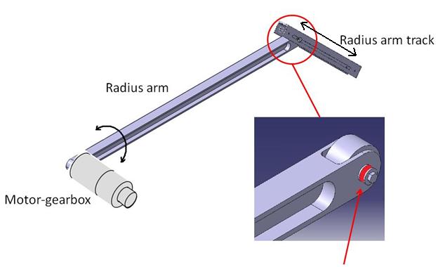
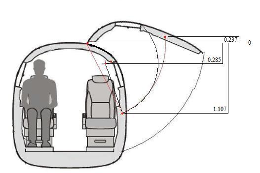
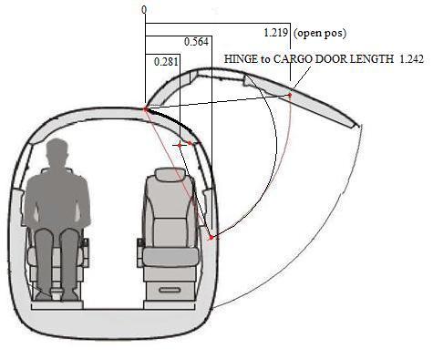
5 5.3 Design options The automation of the cargo door requires a method of assisting or operating both the opening and closing of the cargo door. Four options were considered, including linear actuators simply replacing the pre-existing gas struts and also mounted across the ceiling of the aircraft and one electrically operated scissor link linear actuator system mounted to either the cabin floor or lower side wall/door opening area. All of these design options were rejected due to: aircraft structural reasons, the cabin space that these methods of actuation and mechanical difficulties Selected design The selected design is an electrically powered system, which drives through a geared rotary actuator located/mounted on the internal side wall of the aircraft, a meter long radius arm. The radius arm rotation controls the position of the cargo door, in both the opening and closing directions. The actuation force of the radius arm, is applied through to the door via the radius arm-track (track), affixed to the door structure. The track allows for the changes in geometry between the arc of the cargo door and the arc of the radius arm. Refer to figure 5. The arm and the track have a method of positive contact throughout the doors operating range so provide for the safety needs. Refer figure 6. This concept, of this selected design, best fulfills the consideration requirements most importantly the mechanism consumed as little cabin space as possible and is relatively simple in its operation Design process After recognizing the need for the design and deciding on the concept of the radius arm mechanism, the following was the design process. 1. Calculating the loads and forces applied by the door and how they would affect the drive mechanism and mounting structure, including dynamic forces. 2. Selecting the motor and gearbox assemblies, according to the loads applied 3. Designing the radius arm and radius arm-track 4. Designing gearbox/motor mounting. The design factor of safety (Kf) in this design is 1.5. The justification for this is that the cargo door operation is not critical to the safe operation of the aircraft. It is purely a supplementary system to the aircraft Calculating forces After selecting this radius arm design, to operate the cargo door, based on elementary values of the door operation, accurate values had to be established. This process was essentially divided into four steps, in the following order: 1. Establishing the known reference points and angles of the cargo doors operation which all calculations could be based. Refer figure Calculating the moment values applied by the weight of the cargo door to the hinge of the cargo door, over its entire operating range. Refer Table 1.
6 3. Calculating the position, of the radius arm on the radius arm-track and the forces applied to the arm throughout the doors travel. Refer to Table 1 4. Calculation of the range of radial and shearing forces applied to, the radius arm, gearbox and motor. Refer to Table 1. Radial forces Rotating force - are compressive, on the radius arm, throughout the doors operating range. - the largest compressive force is applied at the cargo door 101 degree angle (fully open) position. - the maximum Radial force, on the radius arm, is 93.6N, with a rotational force of 68.7N. - are all in the negative direction throughout the doors operating range (naturally closing the cargo door closed) - the largest rotating force is applied at the cargo door 45 degree angle position. - the maximum rotating force is N, with a compressive force on the arm is 60.7Nm. This force applies a 135.9Nm torque at the gearbox output shaft Electric motor and gearbox - selection. The retro-fit design uses preexisting commercially available electric motor and gearbox assemblies. Use of these pre-existing components allows for simplicity and cost effective along with ease and cost effective future maintenance these components. The size of the motor and gearbox output shaft diameter is dictated by the peak torque and radial loads being applied to it by the cargo door. The gearbox output shaft diameter then dictates aspects of the radius arm design. The motor/gearbox assembly selection was based on the following constraints: 24VDC electric motor due the electrical power constrictions of the aircraft a gearbox, thence motor, maximum normal operating torque limitation of 135.9Nm. a gearbox that permits a radial load greater than 93.6 N Using these constraints the following motor gearbox assembly was selected, from a particular vendor (refer figure 8): 28VDC motor rated at 2500 RPM when combined with the selected gearbox, will draw 5 amperes during its peak operation. coupled with a failsafe brake unit, that has a spring applied friction brake that is released when electrical power is applied to the motor. the motor is also coupled with an encoder that provides an adjustable internal position limitation control to the motor. This would be set to slow then shut off the motor at the full extension and closing positions of the doors operation. The use of the motor encoder removes the need for additional door operation control witches and sensor needing to be installed on the cargo door itself.
7 the gearbox is a 1:400 ratio unit with a normal operating torque limitation of 164.7Nm and a peak maximum torque of 257.4Nm (within the factor of safety limit of 203.8Nm) the gearbox output shaft is 12.8mm (0.5in) diameter with a No.606 Woodruff key drive shaft Electric motor and gearbox mount design As the suitable engineering information about the aircraft structure is unavailable for this project, a full design of the motor/gearbox mount is not provided, except for the concept design. The mount would be a suitably made to adapt to the aircraft internal side wall and cargo door aperture structure. It would be in the same position and eventually taking the place of the current fitting for the gas-assist strut for the cargo door. The mounting structure would attach to the gearbox portion of the motor/gearbox assembly. This would allow for the removal and replacement of the electric motor (the most likely part of the design that would need to be replaced or regularly overhauled) without having to affect the safety or operation of the remaining door operating system Radius arm-track design (Refer figure 9) The design of the radius arm and the track has to for fill the following limitations: maximum width of the track being 50mm to fit within the preexisting clearance between the cargo door and the door frame aperture. a positive control and connection between the radius arm and radius arm-track to ensure that under normal operation the arm and door do not become disengaged from each other. able to withstand the maximum rotating load applied to the radius arm of 216N. The design of the radius arm-track is essentially a 500mm (19.6in) long inverted U shaped channel in which the roller bearing, connected to the radius arm, runs to transmit the loads between the cargo door and the actuator drive. This track is rigidly connected to the cargo door by the use of two 6.4mm (0.25in) bolts. These two bolts also serve two needs to attach the track to the door and as a mechanical means preventing the radius arm bearing from inadvertently extending beyond the track limits. The two bolts have an external bushing installed over them and between the two inner faces of the channel to provide strength and rigidity to the track. One side of the track has an elongated cut out for the for a guide bolt, from the radius arm bearing, to travel along, to ensure a method of positive contact throughout the doors operating range. This safeties the radius arm to the radius arm-track. The radius arm track is has a range of forces applied to it over the cargo doors operation. The largest is 216N when the cargo door is at 45 degree angle, at which point the radius arm contact point is essentially 50mm from one end of the radius arm track. This force is applied in the centre of the channel with the force distributed through the side walls of the channel and carried into the cargo structure by the two bolts previously mentioned. The resulting loads applied at each bolt location, are: Bolt A 22.5N and Bolt B 194.0N.
8 The selected 6.4mm (1/4in) dia. bolt for the installation will need support a τave = 2.75MPa. The radius arm-track, with 3mm side walls, will need be manufactured of a material that can withstand a shear stress of 1.52MPa Radius arm design The radius arm is a 1292 mm (50.9in) long arm (with an effective length of 1242 mm (48.9in)) that provides the drive from the motor/gearbox to the radius arm-track, attached to the cargo door. The arm is attached to the gearbox output shaft via Woodruff key installation. The contact point between the radius arm and the radius arm-track is made through a 60mm diameter roller bearing which is attached to the radius arm and rolls along the track. Refer figures 10. The radius arm was designed under the following specific requirements: the 12.8mm (0.5 inch) drive shaft and the No.606 Woodruff key provided by the shaft manufacture. the maximum sheering load applied to the radius arm of N the maximum radial compressive load applied to the radius arm of 93.6 N the maximum torque load applied to the radius arm at the gearbox shaft is Nm maximum width of the arm being 42mm to fit within the internal dimension of the radius arm track Bearing installation. The bearing is installed by a single through bolt in the radius arm. The bolt passes from the outside of the radius arm track through a bushing and the slotted track in the radius arm track, through one side of the forked end in the radius arm, then the bearing, finally being secured through the second side of the fork. Ref figure Radius arm. The radius arm is designed as a modified I style beam. The web sections extending to the full width of the arm (43mm) at the fork end to provide for the bearing installation and also at the drive shaft attach end to allow maximum contact area with the key drive, refer figure 10. As the maximum stress is located at the drive shaft connection, the design of the main section of the arm would be calculated to below these stress limitations. The general profile of the radius arm, except for the drive and bearing attachments, is shown in figure 11. The maximum stress in the radius arm is located at the drive key area where the gearbox drive shaft attaches. Material selection for the radius arm, is based on these stresses Cargo door actuation system The automated cargo door operation will be accomplished by either one of two methods. Normally, the door would be opened and closed using a selection switch mounted on the aircraft cabin side wall. The selection switch would be connected in series with a master switch and electrical circuit protection devices used and standard aircraft electrical designs. The door would
9 be powered from a hot DC bus within the aircraft from the aircraft battery or a supplemental DC system. Alternately operated through a mechanical adaptor with the use of a (standard tool) 3/8 drive ratchet wrench through the brake unit, mounted on the top of the electric motor. The cargo door actuation system can be manufactured using the proposed design (section 5.4.1) and complying with the limitations imposed by the pre-existing aircraft design. The estimated total weight of the installation is 11.73kg (25.8lbs) less the estimated weight of removed aircraft component due to the modification, the total weight increase per aircraft is estimated as 10.75kg (23.6lbs). Refer Table 2. The radius arm actuation mechanism, consumes an additional cabin space of approximately: 330mm (13in) longitudinally, 80mm (3.1in) vertically and 80mm (3.1in) laterally. This area is located on forward side wall of the cargo door opening, located 1100mm (43.3in) from the aircraft cabin floor. 6. Project design limitations Information of the pre-existing aircraft structure is not readily available therefore a full adaption of the modification cannot totally assessed. Although every attempt was made in the designed modification, to place loads in know pre-existing load bearing locations it is reasonable that modification can be adapted to the aircraft. 7. References [1] M.F. Spotts etal, Design of Machine Elements, Pearson Education International, 2004 [2] F.P. Beer etal, Mechanics of Materials, McGraw Hill, 2009 [3] F.P. Beer etal, Vctor Mechanics for Engineers Statics and Dynamics, McGraw Hill, 2007 [4] Hossein Rahemi, Finite Element with Matlab Application. Vaughn College of Aeronautics and Technology, 2006.
 cargo door, with the smaller airstair door located within the cargo")
10 Figure 1 Airstair door location Figure 2 Airstair door (open) Figure 3 Shows the size and location of the (larger) cargo door, with the smaller airstair door located within the cargo door.

11 Figure 4 Cargo door (open). Figure 5 Radius arm design

12 Figure 6 Radius arm assy
13 Guidance bolt/bearing Figure 7 Reference points for calculations


14 Figure 8 Electrical motor/gearbox (rotary actuator) unit Figure 9 Radius arm-track
 (Aluminum Alloy 6061T6) radius arm track")
 Effective weight of modification weight 4.21kg 6.23kg 0.79kg 0.50kg 11.")
15 Figure 10 Radius arm Figure 11 Radius arm cross-section t = 6mm Table 2 Weights Item motor/gearbox/encoder radius arm assy (inc bearing) (Aluminum Alloy 6061T6) radius arm track (Aluminum Alloy 7075T6) wiring and hardware TOTAL WEIGHT of installation less removed components from aircraft (approx) Effective weight of modification weight 4.21kg 6.23kg 0.79kg 0.50kg 11.73kg 1.00kg 10.73kg
(deg) angle from vertical")


16 Table 1 Moment and load calculations ANGLE OF DOOR ACTUATOR ARM ANGLE MOMENT APPLIED TO DOOR HINGE BY DOOR WEIGHT FORCE OF DOOR: APPLIED AT ACTUATOR CONTACT POINT COMPRESSIVE FORCE APPLIED TO RADIUS ARM hinge to CofG (from vertical)(deg) angle from vertical (deg) (Nm) (N) (N)
17
18 ETD 541
The Ladder Climber. Design Team. Design Advisor
 The Ladder Climber Design Team Younes Albahrani, Saad Farhad Andres Janna, Jhony Quintal, Shahan Sarkissian Design Advisor Prof. Hamid Hashemi Abstract The goal of this project was to create a low cost
SAE Baja - Drivetrain
 SAE Baja - Drivetrain By Ricardo Inzunza, Brandon Janca, Ryan Worden Team 11 Engineering Analysis Document Submitted towards partial fulfillment of the requirements for Mechanical Engineering Design I
Kaydon white paper The thin section bearing of today
 The thin section bearing of today by Joe Zagar, engineering specialist an SKF Group brand Thin section bearings provide space, save weight The ubiquitous ball bearing was a workhorse of industry throughout
The American Road Machinery Company 17, 25, 30 CUBIC YARD CHASSIS OR ROLLOFF MOUNT LEAF COLLECTOR June 2015
 GENERAL: This specification describes a self-contained engine-driven vacuum leaf-collecting machine. The leaf collector is chassis or roll off mounted, designed for one-person operation, and capable of
Design Considerations for Stability: Civil Aircraft
 Design Considerations for Stability: Civil Aircraft From the discussion on aircraft behavior in a small disturbance, it is clear that both aircraft geometry and mass distribution are important in the design
Revisiting the Calculations of the Aerodynamic Lift Generated over the Fuselage of the Lockheed Constellation
 Eleventh LACCEI Latin American and Caribbean Conference for Engineering and Technology (LACCEI 2013) International Competition of Student Posters and Paper, August 14-16, 2013 Cancun, Mexico. Revisiting
Redesign of Drive Shaft`s tripod Assembly, to improve the performance & reduce failure
 IOSR Journal of Mechanical and Civil Engineering (IOSR-JMCE) e-issn: 2278-1684,p-ISSN: 2320-334X, Volume 11, Issue 2 Ver. IV (Mar- Apr. 2014), PP 81-87 Redesign of Drive Shaft`s tripod Assembly, to improve
Riverhawk Company 215 Clinton Road New Hartford NY (315) Free-Flex Flexural Pivot Engineering Data
 Free-Flex Flexural Pivot Engineering Data") Riverhawk Company 215 Clinton Road New Hartford NY (315)768-4937 Free-Flex Flexural Pivot Engineering Data PREFACE Patented Flexural Pivot A unique bearing concept for applications with limited angular
Riverhawk Company 215 Clinton Road New Hartford NY (315)768-4937 Free-Flex Flexural Pivot Engineering Data PREFACE Patented Flexural Pivot A unique bearing concept for applications with limited angular
SOLUTIONS FOR SAFE HOT COIL EVACUATION AND COIL HANDLING IN CASE OF THICK AND HIGH STRENGTH STEEL
 SOLUTIONS FOR SAFE HOT COIL EVACUATION AND COIL HANDLING IN CASE OF THICK AND HIGH STRENGTH STEEL Stefan Sieberer 1, Lukas Pichler 1a and Manfred Hackl 1 1 Primetals Technologies Austria GmbH, Turmstraße
HYDRAULIC ACTUATOR REPLACEMENT USING ELECTROMECHANICAL TECHNOLOGY
 HYDRAULIC ACTUATOR REPLACEMENT USING ELECTROMECHANICAL TECHNOLOGY SCOPE This white paper discusses several issues encountered by Lee Air with past projects that involved the replacement of Hydraulic Actuators
AIRCRAFT DESIGN SUBSONIC JET TRANSPORT
 AIRCRAFT DESIGN SUBSONIC JET TRANSPORT Analyzed by: Jin Mok Professor: Dr. R.H. Liebeck Date: June 6, 2014 1 Abstract The purpose of this report is to design the results of a given specification and to
Design and Fabrication of Automated Hacksaw Machine
 Design and Fabrication of Automated Hacksaw Machine D.V.Sabariananda 1, V.Siddhartha 1, B.Sushil Krishnana 1, T.Mohanraj 2 UG Student [Mechatronics], Dept. of Mechatronics Engineering, Kongu Engineering
Bearings. Rolling-contact Bearings
 Bearings A bearing is a mechanical element that limits relative motion to only the desired motion and at the same time it reduces the frictional resistance to the desired motion. Depending on the design
White paper: Pneumatics or electrics important criteria when choosing technology
 White paper: Pneumatics or electrics important criteria when choosing technology The requirements for modern production plants are becoming increasingly complex. It is therefore essential that the drive
A Quick reference guide to the installation of Uniflex. Oldham Seals Group. Uniflex installation Guide
 A Quick reference guide to the installation of Uniflex. Oldham Seals Group Uniflex installation Guide Uniflex Guide From Oldham Seals Group Introduction: Uniflex systems provide a means of remote Valve
Design And Development Of Roll Cage For An All-Terrain Vehicle
 Design And Development Of Roll Cage For An All-Terrain Vehicle Khelan Chaudhari, Amogh Joshi, Ranjit Kunte, Kushal Nair E-mail : khelanchoudhary@gmail.com, amogh_4291@yahoo.co.in,ranjitkunte@gmail.com,krockon007@gmail.com
Huco Dynatork Flexible Couplings
 Huco Dynatork Flexible Couplings Flexible Couplings The Company & Its Products Huco products are manufactured in Hertford, England, in a modern plant equipped with all necessary design, development, toolroom
VEHICLE DYNAMICS CONTROL (VDC)
") VEHICLE DYNAMICS CONTROL (VDC) SYSTEM 1. Vehicle Dynamics Control (VDC) System A: GENERAL The vehicle dynamics control (VDC) system is a driver assist system which enhances vehicle s running stability
VEHICLE DYNAMICS CONTROL (VDC) SYSTEM 1. Vehicle Dynamics Control (VDC) System A: GENERAL The vehicle dynamics control (VDC) system is a driver assist system which enhances vehicle s running stability
Precision Modules PSK
 Precision Modules PSK The Drive & Control Company Rexroth Linear Motion Technology Ball Rail Systems Roller Rail Systems Standard Ball Rail Systems Super Ball Rail Systems Ball Rail Systems with Aluminum
TRANSLATION (OR LINEAR)
") 5) Load Bearing Mechanisms Load bearing mechanisms are the structural backbone of any linear / rotary motion system, and are a critical consideration. This section will introduce most of the more common
5) Load Bearing Mechanisms Load bearing mechanisms are the structural backbone of any linear / rotary motion system, and are a critical consideration. This section will introduce most of the more common
SAE Baja - Drivetrain
 SAE Baja - Drivetrain By Ricardo Inzunza, Brandon Janca, Ryan Worden Team 11A Concept Generation and Selection Document Submitted towards partial fulfillment of the requirements for Mechanical Engineering
Vibration damping precision couplings
 Vibration damping precision couplings In light of the advantages of elasticity, strength, resilience, and damping effects, elastomer materials are now being used in most areas of mechanical engineering.
Chapter 7: DC Motors and Transmissions. 7.1: Basic Definitions and Concepts
 Chapter 7: DC Motors and Transmissions Electric motors are one of the most common types of actuators found in robotics. Using them effectively will allow your robot to take action based on the direction
Development of Engine Clutch Control for Parallel Hybrid
 EVS27 Barcelona, Spain, November 17-20, 2013 Development of Engine Clutch Control for Parallel Hybrid Vehicles Joonyoung Park 1 1 Hyundai Motor Company, 772-1, Jangduk, Hwaseong, Gyeonggi, 445-706, Korea,
COMPARISON BETWEEN FMVSS No. 206 and ECE R11
 Informal document No. 15 31st GRSP May 2002 COMPARISON BETWEEN FMVSS No. 206 and ECE R11 DOOR COMPONENT A. Application 1. Vehicles a. Passenger Cars b. MPVs c. Trucks U.S. - FMVSS 206 Differences in ECE
CIRRUS AIRPLANE MAINTENANCE MANUAL
 MODEL SR PASSENGER AND CREW DOORS. DESCRIPTION AND OPERATION Serials 000 thru 00: The two crew/passenger doors incorporate a flush-mount outside door handle, key-operated door lock, and a conventional
HCB-8 AFTER BLENDING. Servoreeler vertical cradle support Registration slots in adapter bracket
 HCB-8 Hard Ceiling Box 8 Square Access Door Ceiling Box Assembly permits the installation of an SRL-8 Servoreeler above a sheetrock or other permanent ceiling structure. The HCB-8 provides service access
9 Locomotive Compensation
 Part 3 Section 9 Locomotive Compensation August 2008 9 Locomotive Compensation Introduction Traditionally, model locomotives have been built with a rigid chassis. Some builders looking for more realism
ROSTA MOTORBASES ROSTA. Self-Tensioning Motor Mount for Belt Drives. without slippage self-adjusting maintenance-free
 MOTORBASES Self-Tensioning Motor Mount for Belt Drives without slippage self-adjusting maintenance-free Technology Tensioning Motorbase Type MB for Belt Drives The elastic tensioning motorbase type MB,
Mechanical Considerations for Servo Motor and Gearhead Sizing
 PDHonline Course M298 (3 PDH) Mechanical Considerations for Servo Motor and Gearhead Sizing Instructor: Chad A. Thompson, P.E. 2012 PDH Online PDH Center 5272 Meadow Estates Drive Fairfax, VA 22030-6658
Linear Actuator with Ball Screw Series OSP-E..S. Contents Description Overview Technical Data Dimensions 79
 Linear Actuator with Ball Screw Series OSP-E..S Contents Description Page Overview 71-74 Technical Data 75-78 Dimensions 79 71 The System Concept ELECTRIC LINEAR ACTUATOR FOR HIGH ACCURACY APPLICATIONS
Design and Analysis of Pressure Die Casting Die for Side Differential Cover of Mini truck
 Design and Analysis of Pressure Die Casting Die for Side Differential Cover of Mini truck 1 A Chakravarthi P.G student, Department of Mechanical Engineering,KSRM CE, kadapa-516003 2. R Rama Krishna Reddy,
IMPACT REGISTER, INC. PRECISION BUILT RECORDERS SINCE 1914
 IMPACT REGISTER, INC. PRECISION BUILT RECORDERS SINCE 1914 RM-3WE (THREE WAY) ACCELEROMETER GENERAL The RM-3WE accelerometer measures and permanently records, for periods of 30, 60, and 90 days, the magnitude,
Uncontrolled copy not subject to amendment. Airframes. Revision 1.00
 Uncontrolled copy not subject to amendment Airframes Revision 1.00 Chapter 4: Fuselage Learning Objectives The purpose of this chapter is to discuss in more detail the first of the 4 major components
Linear Actuator with Toothed Belt Series OSP-E..B
 Linear Actuator with Toothed Belt Series OSP-E..B Contents Description Data Sheet No. Page Overview 1.20.001E 21-24 Technical Data 1.20.002E-1 to 5 25-29 Dimensions 1.20.002E-6 30 Order Instructions 1.20.002E-7
HIGH VOLTAGE vs. LOW VOLTAGE: POTENTIAL IN MILITARY SYSTEMS
 2013 NDIA GROUND VEHICLE SYSTEMS ENGINEERING AND TECHNOLOGY SYMPOSIUM POWER AND MOBILITY (P&M) MINI-SYMPOSIUM AUGUST 21-22, 2013 TROY, MICHIGAN HIGH VOLTAGE vs. LOW VOLTAGE: POTENTIAL IN MILITARY SYSTEMS
ISSN: [Patil et al., 5(10): October, 2016] Impact Factor: 4.116
![ISSN: [Patil et al., 5(10): October, 2016] Impact Factor: 4.116](/thumbs/83/88212336.jpg "ISSN: [Patil et al., 5(10): October, 2016] Impact Factor: 4.116") IJESRT INTERNATIONAL JOURNAL OF ENGINEERING SCIENCES & RESEARCH TECHNOLOGY DESIGN AND ANALYSIS OF TELESCOPIC HALFSHAFT FOR AN ALL-TERRAIN VEHICLE (ATV) Chirag Patil *, Sandeep Imale, Kiran Hiware, Sumeet
IJESRT INTERNATIONAL JOURNAL OF ENGINEERING SCIENCES & RESEARCH TECHNOLOGY DESIGN AND ANALYSIS OF TELESCOPIC HALFSHAFT FOR AN ALL-TERRAIN VEHICLE (ATV) Chirag Patil *, Sandeep Imale, Kiran Hiware, Sumeet
Linear Actuator with Ball Screw Series OSP-E..S. Contents Description Overview Technical Data Dimensions 89
 Linear Actuator with Ball Screw Series OSP-E..S Contents Description Page Overview 79-82 Technical Data 83-88 Dimensions 89 79 The System Concept ELECTRIC LINEAR ACTUATOR FOR HIGH ACCURACY APPLICATIONS
RTM COMPOSITE LUGS FOR HIGH LOAD TRANSFER APPLICATIONS
 25 TH INTERNATIONAL CONGRESS OF THE AERONAUTICAL SCIENCES RTM COMPOSITE LUGS FOR HIGH LOAD TRANSFER APPLICATIONS Markus Wallin*, Olli Saarela*, Barnaby Law**, Tommi Liehu*** *Helsinki University of Technology,
Simulating Rotary Draw Bending and Tube Hydroforming
 Abstract: Simulating Rotary Draw Bending and Tube Hydroforming Dilip K Mahanty, Narendran M. Balan Engineering Services Group, Tata Consultancy Services Tube hydroforming is currently an active area of
CONTRIBUTION TO THE CINEMATIC AND DYNAMIC STUDIES OF HYDRAULIC RADIAL PISTON MOTORS.
 Ing. MIRCEA-TRAIAN CHIMA CONTRIBUTION TO THE CINEMATIC AND DYNAMIC STUDIES OF HYDRAULIC RADIAL PISTON MOTORS. PhD Thesis Abstract Advisor, Prof. dr. ing. matem. Nicolae URSU-FISCHER D.H.C. Cluj-Napoca
Bushing connector application in Suspension modeling
 Bushing connector application in Suspension modeling Mukund Rao, Senior Engineer John Deere Turf and Utility Platform, Cary, North Carolina-USA Abstract: The Suspension Assembly modeling in utility vehicles
Functional Testing & Analysis
 Functional Testing & Analysis We've been providing turnkey Function Test Systems with Monitoring for over 25 years. From valve testing to seat slide exercise we have sensors to fit, cables to connect,
Modular Analysis of Main Rotor Blade of Light Helicopter using FEM
 Modular Analysis of Main Rotor Blade of Light Helicopter using FEM Mahesh N V 1, Raghu T 2 Schlor, IVth Semester M. Tech(Design Engineering), 2 Assistant Professor 1, 2 Mechanical Engineering Department
Extremely High Load Capacity Tapered Roller Bearings
 New Product Extremely High Load Capacity Tapered Roller Bearings Takashi UENO Tomoki MATSUSHITA Standard tapered roller bearing Extreme high load capacity bearing NTN developed a tapered roller bearing
CONTENT. 1. Syllabus 2. Introduction 3. Shaft 4. Coupling. Rigid coupling. Flange coupling. Sleeve (or) muff coupling Split muff coupling
 muff coupling Split muff coupling") UNIT II 1. Syllabus 2. Introduction 3. Shaft 4. Coupling Rigid coupling CONTENT Flange coupling Protected flange coupling Unprotected flange coupling Marine type flange coupling Sleeve (or) muff coupling
UNIT II 1. Syllabus 2. Introduction 3. Shaft 4. Coupling Rigid coupling CONTENT Flange coupling Protected flange coupling Unprotected flange coupling Marine type flange coupling Sleeve (or) muff coupling
White Paper. Electromechanical Actuators in the Automotive Industry Roller screw actuators for weld gun applications
 White Paper Electromechanical Actuators in the Automotive Industry Roller screw actuators for weld gun applications Exlar electric roller screw linear actuators, rotary servo motors, and integrated control
Fundamentals of Steering Systems ME5670
 Fundamentals of Steering Systems ME5670 Class timing Monday: 14:30 Hrs 16:00 Hrs Thursday: 16:30 Hrs 17:30 Hrs Lecture 3 Thomas Gillespie, Fundamentals of Vehicle Dynamics, SAE, 1992. http://www.me.utexas.edu/~longoria/vsdc/clog.html
Understanding the benefits of using a digital valve controller. Mark Buzzell Business Manager, Metso Flow Control
 Understanding the benefits of using a digital valve controller Mark Buzzell Business Manager, Metso Flow Control Evolution of Valve Positioners Digital (Next Generation) Digital (First Generation) Analog
Electromagnetic Fully Flexible Valve Actuator
 Electromagnetic Fully Flexible Valve Actuator A traditional cam drive train, shown in Figure 1, acts on the valve stems to open and close the valves. As the crankshaft drives the camshaft through gears
Technical Math 2 Lab 3: Garage Door Spring 2018
 Name: Name: Name: Name: As you may have determined the problem is a broken spring (clearly shown on the left in the picture below) which needs to be replaced. I. Garage Door Basics: Common residential
EMC-HD. C 01_2 Subheadline_15pt/7.2mm
 C Electromechanical 01_1 Headline_36pt/14.4mm Cylinder EMC-HD C 01_2 Subheadline_15pt/7.2mm 2 Elektromechanischer Zylinder EMC-HD Short product name Example: EMC 085 HD 1 System = ElectroMechanical Cylinder
DOORS Table of Contents REV 3, May 03/05 CHAPTER DOORS. INTRODUCTION Introduction System Circuit Breakers
 Vol. 1 06--00--1 DOOR Table of Contents REV 3, May 03/05 CHAPTER 6 --- DOOR Page TABLE OF CONTENT 06-00 -1 Table of Contents 06--00--1 INTRODUCTION 06-10 -1 Introduction 06--10--1 ystem Circuit Breakers
Smart Automated Vent Register Using an SMA Spring Actuated Rotary Ratchet
 Smart Automated Vent Register Using an SMA Spring Actuated Rotary Ratchet Mary Molepske, Victor Braciszewski, James Butler, Gregory Caputo, Fan-Ning Cheng, WonHee Kim, Jonathan Luntz, Diann Brei ABSTRACT
2300 OPERATING/APPLICATION/INSTALLATION INSTRUCTIONS
 2300 OPERATING/APPLICATION/INSTALLATION INSTRUCTIONS GENERAL The POWER ACCESS Model 2300 is an automatic door opener designed for opening and closing side hinged residential doors - both exterior and interior.
Single Pole Circuit Protectors 55. Multi-Pole Circuit Protectors 56. Configurations 58. Operating Characteristics 59.
 Single Pole Circuit Protectors 55 Multi-Pole Circuit Protectors 56 Configurations 58 Operating Characteristics 59 Delay Curves 60 Specifications 61 Decision Tables 62 SINGLE POLE CIRCUIT PROTECTORS The
AGN 076 Alternator Bearings
 Application Guidance Notes: Technical Information from Cummins Generator Technologies AGN 076 Alternator Bearings BEARING TYPES In the design of STAMFORD and AvK alternators, the expected types of rotor
NODIA AND COMPANY. Model Test Paper - I GATE Machine Design. Copyright By Publishers
 No part of this publication may be reproduced or distributed in any form or any means, electronic, mechanical, photocopying, or otherwise without the prior permission of the author. Model Test Paper -
Installation and Set-Up Manual
 MAXX LNX Power Center Mount Legrest Installation and Set-Up Manual NOTE: This manual contains important information related to the installation, set-up and adjustment of our Maxx Pivot Plus Legrests. Please
ASME Human Powered Vehicle
 ASME Human Powered Vehicle By Yousef Alanzi, Evan Bunce, Cody Chenoweth, Haley Flenner, Brent Ives, and Connor Newcomer Team 14 Mid-Point Review Document Submitted towards partial fulfillment of the requirements
Design and Vibrational Analysis of Flexible Coupling (Pin-type)
") Design and Vibrational Analysis of Flexible Coupling (Pin-type) 1 S.BASKARAN, ARUN.S 1 Assistant professor Department of Mechanical Engineering, KSR Institute for Engineering and Technology, Tiruchengode,
Design and Vibrational Analysis of Flexible Coupling (Pin-type) 1 S.BASKARAN, ARUN.S 1 Assistant professor Department of Mechanical Engineering, KSR Institute for Engineering and Technology, Tiruchengode,
DESIGN AND DEVELOPMENT OF IC ENGINE GO-KART
 DESIGN AND DEVELOPMENT OF IC ENGINE GO-KART AkshayB. Khot 1, KunalJ. Mahekar 2, VaibhavJ. Mahekar 3, GurunathS. Patil 4, MohanishM. Patil 5, Prof. S. P. Jarag 6 BE Student, Department of Mechanical Engineering,
Linear Motion Technology Handbook. The Drive & Control Company
 Linear Motion Technology Handbook The Drive & Control Company 1-2 Bosch Rexroth AG Linear Motion Technology Handbook R310EN 2017 (2006.07) Linear Motion and Assembly Technologies www.boschrexroth.com/brl
AN INTEGRATED MODULAR TEST RIG FOR LANDING GEAR FATIGUE AND STRENGTH TESTING
 ICAS2002 CONGRESS AN INTEGRATED MODULAR TEST RIG FOR LANDING GEAR FATIGUE AND STRENGTH TESTING R. Kyle Schmidt, P. Eng. Messier-Dowty Inc., Ajax, Ontario, Canada Keywords: landing gear, fatigue, strength,
Boombot: Low Friction Coefficient Stair Climbing Robot Using Rotating Boom and Weight Redistribution
 Boombot: Low Friction Coefficient Stair Climbing Robot Using Rotating Boom and Weight Redistribution Sartaj Singh and Ramachandra K Abstract Boombot comprising four wheels and a rotating boom in the middle
Stearns Heavy Duty Clutches & Brakes... Rugged, Reliable
 Stearns Heavy Duty Clutches & Brakes... Rugged, Reliable Stearns heavy duty clutches and brakes represent over 75 years of design, engineering and on-the-job experience. Stearns products are backed by
Lifting Columns. Self Supporting, Compact and Versatile Linear Motion for Quicker Throughput, Minimal Downtime and No Maintenance
 Self Supporting, Compact and Versatile Linear Motion for Quicker Throughput, Minimal Downtime and No Maintenance New! Now Available in Three Models Each with Unique Features Introducing the Thomson Lifting
ROTARY MOTION CONTROL
 ROTARY MOTION ONTROL Technical Data Sheet Mechanical Torque Limiter The trend in industry is to design and incorporate more automation into production processes. Machines are becoming more accurate, requiring
SAE Mini BAJA: Suspension and Steering
 SAE Mini BAJA: Suspension and Steering By Zane Cross, Kyle Egan, Nick Garry, Trevor Hochhaus Team 11 Progress Report Submitted towards partial fulfillment of the requirements for Mechanical Engineering
Analysis of Turn Table Assembly of Semi- Automatic High Pressure Molding Machine
 Kalpa Publications in Engineering Volume 1, 2017, Pages 259 264 ICRISET2017. International Conference on Research and Innovations in Science, Engineering &Technology. Selected Papers in Engineering Analysis
Maxx LNX Power Center Mount Legrest
 Maxx LNX Power Center Mount Legrest Installation, Set-Up & Adjustment TRD0341 Rev A - 2 - - 3 - Important! The most important link in the delivery chain is the end user. The user must be satisfied with
MSI SINGLE IDLER BELT SCALE
 MSI SINGLE IDLER BELT SCALE Instruction Manual PL-319 January 2001 33453190 Rev. 1.2 Safety Guidelines Warning notices must be observed to ensure personal safety as well as that of others, and to protect
Generator Termination Bus-bar Arrangement - Design requirements: Utility Perspective
 Generator Termination Bus-bar Arrangement - Design requirements: Utility Perspective D. K. Chaturvedi (NTPC) Harshvardhan Senghani (NTPC) K Venugopal (CS Electric) This paper appraise user on the termination
6-speed manual gearbox 0A5
 Service Training Self-study programme 320 6-speed manual gearbox 0A5 Design and function S320_002 In addition to meeting increasing technical demands, modern cars also have to represent effective space
Design, Modelling & Analysis of Double Wishbone Suspension System
 Design, Modelling & Analysis of Double Wishbone Suspension System 1 Nikita Gawai, 2 Deepak Yadav, 3 Shweta Chavan, 4 Apoorva Lele, 5 Shreyash Dalvi Thakur College of Engineering & Technology, Kandivali
Miniature Ball Rail Systems
 R310EN 2210 (2004.06) The Drive & Control Company 2 Bosch Rexroth AG Linear Motion and Assembly Technologies Miniature-BRS R310EN 2210 (2004.06) Linear Motion Systems Ball Rail System Standard Ball Rail
Design and Analysis of Spring-Ball Clutch Torque Limiter
 Design and Analysis of Spring-Ball Clutch Torque Limiter Nasiket M. Gawas, Manali S. Patkar, Prasad B. Gawade 1 B.E Student, B.E Student, 3 B.E Student Mechanical Engineering, Finolex Academy of Management
CRANE TESTING REQUIREMENTS FOR PERFORMANCE TESTS
 APPENDIX I CRANE TESTING REQUIREMENTS FOR PERFORMANCE TESTS 1. PERFORMANCE TESTING. a. Performance testing includes both operational performance testing and load performance testing. The following tables
Shaft-Hub-Connections
 Stand: 14.01.2010 Shaft-Hub-Connections Shrink Discs Cone Clamping Elements Star Discs 36 Edition 2012/2013 RINGSPANN Eingetragenes Warenzeichen der RINGSPANN GmbH, Bad Homburg Table of Contents Introduction
PIONEER RESEARCH & DEVELOPMENT GROUP
 Design and Stress Analysis of Tow Bar for Medium Sized Portable Compressors Pankaj Khannade 1, Akash Chitnis 2, Gangadhar Jagdale 3 1,2 Mechanical Department, University of Pune/ Smt. Kashibai Navale College
Candy Coup-Link OVER YEARS OF INNOVATION
 Candy Coup-Link Zero-backlash, flexible-shaft couplings High torque, excellent response Accommodates misalignment and shaft endplay Aluminum and stainless steel options Inch and metric bores available
Rodless Pneumatic Cylinders Series OSP-P
 Rodless Pneumatic Cylinders Series OSP-P System Concepts & Components... 2-5 Technical Data... 7-9 Dimensions... 10-15 Active rakes... 16-19 Accessories (Mounts & Supports)... 20-29 Ordering Information...30
III B.Tech I Semester Supplementary Examinations, May/June
 Set No. 1 III B.Tech I Semester Supplementary Examinations, May/June - 2015 1 a) Derive the expression for Gyroscopic Couple? b) A disc with radius of gyration of 60mm and a mass of 4kg is mounted centrally
Hybrid Architectures for Automated Transmission Systems
 1 / 5 Hybrid Architectures for Automated Transmission Systems - add-on and integrated solutions - Dierk REITZ, Uwe WAGNER, Reinhard BERGER LuK GmbH & Co. ohg Bussmatten 2, 77815 Bühl, Germany (E-Mail:
Static Structural and Thermal Analysis of Aluminum Alloy Piston For Design Optimization Using FEA Kashyap Vyas 1 Milan Pandya 2
 IJSRD - International Journal for Scientific Research & Development Vol. 2, Issue 03, 2014 ISSN (online): 2321-0613 Static Structural and Thermal Analysis of Aluminum Alloy Piston For Design Optimization
Tiger Lifting Home of the Tiger hoisting, winching and height safety ranges
 Tiger Professional Lever Hoist Model No. PROLH with optional travelling end stop with spark resistant components with overload protection Main Features DNV GL Verification tested according to NORSOK R-002
NOTICE. The above identified patent application is available for licensing. Requests for information should be addressed to:
 Serial Number 09/652.303 Filing Date 28 August 2000 Inventor Antoniko M. Amaral Stanley J. Olson NOTICE The above identified patent application is available for licensing. Requests for information should
HOW BELT DRIVES IMPACT OVERHUNG LOAD
 HOW BELT DRIVES IMPACT OVERHUNG LOAD HOW TO IMPROVE WORKER SAFETY AND REDUCE MAINTENANCE Introduction Today s belt drive systems are capable of transmitting enormous power in a compact space. What impact
Robot Arm with Conveyor Belts
 Robot Arm with Conveyor Belts This example models a robotic arm and two conveyor belts. One conveyor belts bring blocks to the robot. The robot grabs the block, flips it over and transfers it to another
DESIGN AND ANALYSIS OF PRE- INSERTION RESISTOR MECHANISM
 DESIGN AND ANALYSIS OF PRE- INSERTION RESISTOR MECHANISM Bhavik Bhesaniya 1, Nilesh J Parekh 2, Sanket Khatri 3 1 Student, Mechanical Engineering, Nirma University, Ahmedabad 2 Assistant Professor, Mechanical
STIFFNESS CHARACTERISTICS OF MAIN BEARINGS FOUNDATION OF MARINE ENGINE
 Journal of KONES Powertrain and Transport, Vol. 23, No. 1 2016 STIFFNESS CHARACTERISTICS OF MAIN BEARINGS FOUNDATION OF MARINE ENGINE Lech Murawski Gdynia Maritime University, Faculty of Marine Engineering
Structural Analysis of Differential Gearbox
 Structural Analysis of Differential Gearbox Daniel Das.A Seenivasan.S Assistant Professor Karthick.S Assistant Professor Abstract- The main aim of this paper is to focus on the mechanical design and analysis
Simulation of Brake Pressure Multiplier (BPM) through ANSYS 14.0 For Effective Braking in ATV
 through ANSYS 14.0 For Effective Braking in ATV") RESEARCH ARTICLE OPEN ACCESS Simulation of Brake Pressure Multiplier (BPM) through ANSYS 14.0 For Effective Braking in ATV Ronak Bandil 2, Anand Baghel 1,Akash Singh Parihar 2, Shubham Kumar Verma 2,Vikas
RESEARCH ARTICLE OPEN ACCESS Simulation of Brake Pressure Multiplier (BPM) through ANSYS 14.0 For Effective Braking in ATV Ronak Bandil 2, Anand Baghel 1,Akash Singh Parihar 2, Shubham Kumar Verma 2,Vikas
The filling pressure of SUSPA gas springs depends on the extension force and the geometry and is between 10 and 230 bar.
 FAQ s 1. Why is there a warning on the gas spring? Gas springs are filled with compressed nitrogen. The warning is intended to prevent unauthorized people from opening the gas spring or making other changes
Bodyshell...2 New features of body structure...2
 Table of Contents Subject Page Bodyshell.................................................2 New features of body structure...............................2 Crash scenarios............................................2
Racing Tires in Formula SAE Suspension Development
 The University of Western Ontario Department of Mechanical and Materials Engineering MME419 Mechanical Engineering Project MME499 Mechanical Engineering Design (Industrial) Racing Tires in Formula SAE
V-Rings around the clock... around the clock...
 Description V-rings are rotary seals that can perform numerous jobs in their function of sealing rotating shafts: sealing against the penetration of dirt, dust, water or watery pollutants, combination
Increase Factor of Safety of Go-Kart Chassis during Front Impact Analysis
 IJIRST International Journal for Innovative Research in Science & Technology Volume 3 Issue 04 September 2016 ISSN (online): 2349-6010 Increase Factor of Safety of Go-Kart Chassis during Front Impact Analysis
High aspect ratio for high endurance. Mechanical simplicity. Low empty weight. STOVL or STOL capability. And for the propulsion system:
 Idealized tilt-thrust (U) All of the UAV options that we've been able to analyze suffer from some deficiency. A diesel, fixed-wing UAV could possibly satisfy the range and endurance objectives, but integration
PAGE DESCRIPTION REF. NO.
 TABLE OF CONTENTS VC 628 / 5520 / 6620 MANUAL PAGE DESCRIPTION REF. NO. 1 READ THIS FIRST... 416756 2 IMPORTANT WARNING... 416086 3 WARNING AND CAUTION DECAL LOCATIONS... 416128 4 DECAL DRAWINGS & LIST...