GE Industrial Solutions ASTAT XL. Installation, connection and operation instructions. GE imagination at work. Original Instruction DET-812 ed.
|
|
|
- Bertina Morton
- 6 years ago
- Views:
Transcription

1 GE Industrial Solutions ASTAT XL Installation, connection and operation instructions GE imagination at work Original Instruction DET-812 ed. 00
2 Contents Contents 1 About This Manual Caution Statements Electrical Shock Risk System Design and Safety of Personnel Disposal Instructions Introduction Feature List Specifications Model Code Current Ratings Dimensions and Weights Specifications UL Compliant Installation Installation Physical Installation Control Terminals Control Wiring Relay Outputs Motor Thermistors Power Terminations Power Input and Output Configurations Schematic Diagrams Power Circuits Motor Connection Bypass Contactor Main Contactor Circuit Breaker Power Factor Correction Earth Terminals Power Supply Fuses Operation The Keypad Starter Status LEDs Displays Start, Stop and Reset Commands Soft Start Methods Stop Methods Jog Operation Inside Delta Operation Programming Menu Quick Setup Standard Menu Extended Menu Parameter Descriptions Adjustment Lock Access Code Setup Tools Logs Menu Trip Log Event Log Performance Counters...54 DET-812 1
3 Contents 10 Application Examples Installation with Main Contactor Installation with Bypass Contactor Emergency Run Operation Auxiliary Trip Circuit DC Brake with External Zero Speed Sensor Soft Braking Two Speed Motor Troubleshooting Protection Responses Trip Messages General Faults Accessories Communication Modules Remote Control Panel (RCP) Finger Guard Kit PC Software Appendix 1: Fuse Selection Tables Bussman Fuses - Square Body (170M) Bussman Fuses - British Style (BS88) Ferraz/Mersen Fuses - HSJ Ferraz/Mersen Fuses - North American Style (PSC 690) Ferraz/Mersen Fuses - European Style (PSC 690) Ferraz/Mersen Fuses - AJT UL Fuse Selection and Short Circuit Ratings Appendix 2: ASTAT XL Output Relay Compatibility Overview Using the Soft Starter to Switch a Contactor Coil DET-812
4 About This Manual 1 About This Manual The examples and diagrams in this manual are included solely for illustrative purposes. The information contained in this manual is subject to change at any time and without prior notice. In no event will responsibility or liability be accepted for direct, indirect or consequential damages resulting from the use or application of this equipment. WARNING Indicates a hazard that may cause personal injury or death. AVERTISSEMENT Indique un risque pouvant provoquer des blessures éventuellement mortelles. CAUTION Indicates a hazard that may damage the equipment or installation. Provides helpful information. DET-812 3
5 Caution Statements 2 Caution Statements Caution Statements cannot cover every potential cause of equipment damage but can highlight common causes of damage. It is the installer's responsibility to read and understand all instructions in this manual prior to installing, operating or maintaining the equipment, to follow good electrical practice including applying appropriate personal protective equipment and to seek advice before operating this equipment in a manner other than as described in this manual. The ASTAT XL soft starter is not user serviceable. The unit should only be serviced by authorised service personnel. Unauthorised tampering with the unit will void the product warranty. 2.1 Electrical Shock Risk The voltages present in the following locations can cause severe electric shock and may be lethal: AC supply cables and connections Output cables and connections Many internal parts of the starter, and external option units The AC supply must be disconnected from the starter using an approved isolation device before any cover is removed from the starter or before any servicing work is performed. WARNING - ELECTRICAL SHOCK HAZARD Models QLxxB0500D~QLxxX1600D: The busbar and heatsink must be treated as live whenever the unit has mains voltage connected (including when the starter is tripped or waiting for a command). AVERTISSEMENT - DANGER D'ELECTROCUTION Modèles QLxxB0500D à QLxxX1600D : Les barres de puissance et le radiateur doivent être traités comme étant des éléments sous tension si l'appareil est relié au secteur (y compris lorsque le démarreur s'est mis en sécurité ou s'il attend une commande). SHORT CIRCUIT The ASTAT XL is not short circuit proof. After severe overload or short circuit, the operation of the ASTAT XL should be fully tested by an authorised service agent. GROUNDING AND BRANCH CIRCUIT PROTECTION It is the responsibility of the user or person installing the ASTAT XL to provide proper grounding and branch circuit protection according to local electrical safety codes. 2.2 System Design and Safety of Personnel The starter is intended as a component for professional incorporation into complete equipment or a system. If installed incorrectly, the starter may present a safety hazard. The starter uses high voltages and currents, carries stored electrical energy, and is used to control equipment which can cause injury. Close attention is required to the electrical installation and the system design to avoid hazards either in normal operation or in the event of equipment malfunction. System design, installation, commissioning and maintenance must be carried out by personnel who have the necessary training and experience. They must read this safety information and this guide carefully. None of the starter functions must be used to ensure safety of personnel, ie they must not be used for safety-related functions. Careful consideration must be given to the functions of the starter which might result in a hazard, either through their intended behaviour or through incorrect operation due to a fault. In any application where a malfunction of the starter or its control system could lead to or allow damage, loss or injury, a risk analysis must be carried out, and where necessary, further measures taken to reduce the risk. The system designer is responsible for ensuring that the complete system is safe and designed correctly according to the relevant safety standards STOP function The STOP function does not remove dangerous voltages from the starter, the motor or any external option units. 4 DET-812
6 Caution Statements 2.3 Disposal Instructions Equipment containing electrical components may not be disposed of together with domestic waste. It must be collected separately as electrical and electronic waste according to local and currently valid legislation. DET-812 5
7 Introduction 3 Introduction 3.1 Feature List Extensive starting and stopping options Adaptive Control Constant Current Current Ramp Timed voltage ramp soft stop Brake Models for all connection requirements 23 A to 1600 A (nominal) 200 VAC to 525 VAC 380 VAC to 690 VAC Internally bypassed options In-line or inside delta connection (auto-detect) Inputs and outputs Remote control inputs (3 x fixed, 1 x programmable) Relay outputs (3 x programmable) Analog output Communication modules: Ethernet (Profinet, Modbus TCP, Ethernet IP), Profibus, DeviceNet, Modbus RTU, and USB Easy-to-read display with comprehensive feedback Multi-language feedback Multiple status screens and performance graphs Date and time stamped event logging Operational counters (number of starts, hours-run, kwh) Performance monitoring (current, voltage, power factor, kwh) User-programmable monitoring screen Customisable protection Motor overload Excess Start Time Undercurrent Instantaneous overcurrent Current imbalance Mains frequency Input Trip Motor thermistor Power circuit Phase sequence 6 DET-812
8 Specifications 4 Specifications 4.1 Model Code Example: Model QL21B0023D Q L 2 1 B 0023 D ASTAT L = XL Series Mains voltage 2 = 200 ~ 525 VAC 4 = 380 ~ 690 VAC Control voltage 1 = 110~120 VAC or 220~240 VAC 2 = 24 VAC/VDC Bypass B = internally bypassed X = non-bypassed Nominal current rating D = Built-in display 4.2 Current Ratings Contact your local supplier for ratings under operating conditions not covered by these ratings charts Current Ratings for Bypass Operation 80 A : AC-53b : 345 Off time (seconds) Start time (seconds) Start current (multiple of motor full load current) Starter current rating (amperes) Models QLxxX0255D~QLxxX1600D must be externally bypassed. DET-812 7
9 Specifications In-line connection AC53b :350 AC53b :345 AC53b :340 AC53b : ºC <1000 metres 40 ºC <1000 metres 40 ºC <1000 metres 40 ºC <1000 metres QLxxB0023D 23 A 20 A 17 A 15 A QLxxB0043D 43 A 37 A 31 A 26 A QLxxB0050D 50 A 44 A 37 A 30 A QLxxB0053D 53 A 53 A 46 A 37 A AC53b :590 AC53b :585 AC53b :580 AC53b : ºC <1000 metres 40 ºC <1000 metres 40 ºC <1000 metres 40 ºC <1000 metres QLxxB0076D 76 A 64 A 55 A 47 A QLxxB0097D 97 A 82 A 69 A 58 A QLxxB0100D 100 A 88 A 74 A 61 A QLxxB0105D 105 A 105 A 95 A 78 A QLxxB0145D 145 A 123 A 106 A 90 A QLxxB0170D 170 A 145 A 121 A 97 A QLxxB0200D 200 A 189 A 160 A 134 A QLxxB0220D 220 A 210 A 178 A 148 A QLxxB0255D 255 A 231 A 201 A 176 A QLxxX0255D 255 A 231 A 201 A 176 A QLxxB0350D 350 A 329 A 284 A 244 A QLxxX0360D 360 A 360 A 310 A 263 A QLxxX0380D 380 A 380 A 359 A 299 A QLxxB0425D 425 A 411 A 355 A 305 A QLxxX0430D 430 A 430 A 368 A 309 A QLxxB0500D 500 A 445 A 383 A 326 A QLxxB0580D 580 A 492 A 425 A 364 A QLxxX0620D 620 A 620 A 540 A 434 A QLxxX0650D 650 A 650 A 561 A 455 A QLxxB0700D 700 A 592 A 512 A 438 A QLxxX0790D 790 A 790 A 714 A 579 A QLxxB0820D 820 A 705 A 606 A 516 A QLxxB0920D 920 A 804 A 684 A 571 A QLxxX0930D 930 A 930 A 829 A 661 A QLxxB1000D 1000 A 936 A 796 A 664 A QLxxX1200D 1200 A 1200 A 1200 A 1071 A QLxxX1410D 1410 A 1410 A 1319 A 1114 A QLxxX1600D 1600 A 1600 A 1600 A 1353 A 8 DET-812
10 Specifications Inside delta connection AC53b :350 AC53b :345 AC53b :340 AC53b : ºC <1000 metres 40 ºC <1000 metres 40 ºC <1000 metres 40 ºC <1000 metres QLxxB0023D 34 A 30 A 26 A 22 A QLxxB0043D 64 A 59 A 51 A 44 A QLxxB0050D 75 A 66 A 55 A 45 A QLxxB0053D 79 A 79 A 69 A 55 A AC53b :590 AC53b :585 AC53b :580 AC53b : ºC <1000 metres 40 ºC <1000 metres 40 ºC <1000 metres 40 ºC <1000 metres QLxxB0076D 114 A 96 A 83 A 70 A QLxxB0097D 145 A 123 A 104 A 87 A QLxxB0100D 150 A 132 A 112 A 92 A QLxxB0105D 157 A 157 A 143 A 117 A QLxxB0145D 218 A 184 A 159 A 136 A QLxxB0170D 255 A 217 A 181 A 146 A QLxxB0200D 300 A 283 A 241 A 200 A QLxxB0220D 330 A 315 A 268 A 223 A QLxxB0255D 382 A 346 A 302 A 264 A QLxxX0255D 382 A 346 A 302 A 264 A QLxxB0350D 525 A 494 A 427 A 366 A QLxxX0360D 540 A 540 A 465 A 395 A QLxxX0380D 570 A 570 A 539 A 449 A QLxxB0425D 638 A 617 A 533 A 458 A QLxxX0430D 645 A 645 A 552 A 464 A QLxxB0500D 750 A 668 A 575 A 490 A QLxxB0580D 870 A 738 A 637 A 546 A QLxxX0620D 930 A 930 A 810 A 651 A QLxxX0650D 975 A 975 A 842 A 683 A QLxxB0700D 1050 A 889 A 768 A 658 A QLxxX0790D 1185 A 1185 A 1071 A 868 A QLxxB0820D 1230 A 1058 A 910 A 774 A QLxxB0920D 1380 A 1206 A 1026 A 857 A QLxxX0930D 1395 A 1395 A 1244 A 992 A QLxxB1000D 1500 A 1404 A 1194 A 997 A QLxxX1200D 1800 A 1800 A 1800 A 1606 A QLxxX1410D 2115 A 2115 A 1979 A 1671 A QLxxX1600D 2400 A 2400 A 2400 A 2030 A DET-812 9
11 Specifications Current Ratings for Continuous Operation (Not bypassed) 351 A : AC-53a : 50-6 In-line connection Starts per hour On-load duty cycle (%) Start time (seconds) Start current (multiple of motor full load current) Starter current rating (amperes) AC53a 3-10:50-6 AC53a :50-6 AC53a 4-20:50-6 AC53a : ºC <1000 metres 40 ºC <1000 metres 40 ºC <1000 metres 40 ºC <1000 metres QLxxX0255D 255 A 222 A 195 A 171 A QLxxX0360D 360 A 351 A 303 A 259 A QLxxX0380D 380 A 380 A 348 A 292 A QLxxX0430D 430 A 413 A 355 A 301 A QLxxX0620D 620 A 614 A 515 A 419 A QLxxX0650D 650 A 629 A 532 A 437 A QLxxX0790D 790 A 790 A 694 A 567 A QLxxX0930D 930 A 930 A 800 A 644 A QLxxX1200D 1200 A 1200 A 1135 A 983 A QLxxX1410D 1410 A 1355 A 1187 A 1023 A QLxxX1600D 1600 A 1600 A 1433 A 1227 A Inside delta connection AC53a 3-10:50-6 AC53a :50-6 AC53a 4-20:50-6 AC53a : ºC <1000 metres 40 ºC <1000 metres 40 ºC <1000 metres 40 ºC <1000 metres QLxxX0255D 382 A 334 A 293 A 257 A QLxxX0360D 540 A 527 A 455 A 388 A QLxxX0380D 570 A 570 A 522 A 437 A QLxxX0430D 645 A 620 A 533 A 451 A QLxxX0620D 930 A 920 A 773 A 628 A QLxxX0650D 975 A 943 A 798 A 656 A QLxxX0790D 1185 A 1185 A 1041 A 850 A QLxxX0930D 1395 A 1395 A 1200 A 966 A QLxxX1200D 1800 A 1800 A 1702 A 1474 A QLxxX1410D 2115 A 2033 A 1780 A 1535 A QLxxX1600D 2400 A 2400 A 2149 A 1840 A 10 DET-812
12 Specifications Minimum and Maximum Current Settings The ASTAT XL's minimum and maximum full load current settings depend on the model: In-line connection Inside delta connection Model Minimum Maximum Minimum Maximum QLxxB0023D 5 A 23 A 5 A 34 A QLxxB0043D 9 A 43 A 9 A 64 A QLxxB0050D 10 A 50 A 10 A 75 A QLxxB0053D 11 A 53 A 11 A 79 A QLxxB0076D 15 A 76 A 15 A 114 A QLxxB0097D 19 A 97 A 19 A 145 A QLxxB0100D 20 A 100 A 20 A 150 A QLxxB0105D 21 A 105 A 21 A 157 A QLxxB0145D 29 A 145 A 29 A 217 A QLxxB0170D 34 A 170 A 34 A 255 A QLxxB0200D 40 A 200 A 40 A 300 A QLxxB0220D 44 A 220 A 44 A 330 A QLxxB0255D 51 A 255 A 51 A 382 A QLxxX0255D 51 A 255 A 51 A 382 A QLxxB0350D 70 A 350 A 70 A 525 A QLxxX0360D 72 A 360 A 72 A 540 A QLxxX0380D 76 A 380 A 76 A 570 A QLxxB0425D 85 A 425 A 85 A 638 A QLxxX0430D 86 A 430 A 86 A 645 A QLxxB0500D 100 A 500 A 100 A 750 A QLxxB0580D 116 A 580 A 116 A 870 A QLxxX0620D 124 A 620 A 124 A 930 A QLxxX0650D 130 A 650 A 130 A 975 A QLxxB0700D 140 A 700 A 140 A 1050 A QLxxX0790D 158 A 790 A 158 A 1185 A QLxxB0820D 164 A 820 A 164 A 1230 A QLxxB0920D 184 A 920 A 184 A 1380 A QLxxX0930D 186 A 930 A 186 A 1395 A QLxxB1000D 200 A 1000 A 200 A 1500 A QLxxX1200D 240 A 1200 A 240 A 1800 A QLxxX1410D 282 A 1410 A 282 A 2115 A QLxxX1600D 320 A 1600 A 320 A 2400 A DET
13 Specifications 4.3 Dimensions and Weights C D A B A B F D C E Height mm (inch) Width mm (inch) Depth mm (inch) Weight kg (lb) Model A B C D E QLxxB0023D QLxxB0043D QLxxB0050D (7.2) (9.0) QLxxB0053D QLxxB0076D (11.6) (10.9) (5.9) (4.9) 4.4 (9.7) QLxxB0097D QLxxB0100D (8.4) (10.8) QLxxB0105D QLxxB0145D 13.6 (30.0) QLxxB0170D (30.4) QLxxB0200D (17.2) (15.0) (10.8) (9.8) (9.8) 14.6 QLxxB0220D (32.2) QLxxB0255D (57.3) QLxxB0350D (17.3) (15.4) (16.7) (14.8) (11.7) 29.4 QLxxB0425D (64.8) QLxxB0500D 49 QLxxB0580D (108.0) QLxxB0700D QLxxB0820D (25.2) (23.6) (17.0) (12.6) (11.5) (137.8) QLxxB0920D 63 QLxxB1000D (138.9) QLxxX0255D 460 (18.1) 400 (15.7) 390 (15.4) 320 (12.6) 278 (10.9) 23 (50.7) QLxxX0360D QLxxX0380D 36 QLxxX0430D (79.4) QLxxX0620D QLxxX0650D (27.1) (20.6) (16.9) (12.6) (11.9) 39.5 QLxxX0790D (87.1) QLxxX0930D 51.5 (113.5) QLxxX1200D (283.3) QLxxX1410D (33.9) (28.6) (22.6) (19.7) (14.3) 130 (286.6) QLxxX1600D 140 (308.6) E 12 DET-812
14 Specifications 4.4 Specifications Supply Mains voltage (L1, L2, L3) VAC ~ 525 VAC (± 10%) VAC ~ 600 VAC (± 10%) (in-line or inside delta connection) VAC ~ 690 VAC (± 10%) (earthed star supply system only) Control voltage (A4, A5, A6) ~ 120 VAC or 220 ~ 240 VAC (+ 10% / -15%), 600mA VAC/VDC ±20%, 2.8A Mains frequency Hz ~ 66 Hz Rated insulation voltage to earth VAC Rated impulse withstand voltage... 4 kv Form designation... Bypassed or continuous, semiconductor motor starter form 1 Short circuit capability Coordination with semiconductor fuses... Type 2 Coordination with HRC fuses... Type 1 QLxxB0023D ~ QLxxB0220D... prospective current 65 ka QLxxB0255D ~ QLxxB1000D... prospective current 85 ka QLxxX0255D ~ QLxxX0930D... prospective current 85 ka QLxxX1200D ~ QLxxX1600D... prospective current 100 ka Electromagnetic capability (compliant with EU Directive 89/336/EEC) EMC Emissions... IEC Class B and Lloyds Marine No 1 Specification EMC Immunity... IEC Inputs Input rating... Active 24 VDC, 8 ma approx Start (54, 55)... Normally Open Stop (56, 57)... Normally Closed Reset (58, 57)... Normally Closed Programmable input (53, 55)... Normally Open Motor thermistor (64, 65)... Trip >3.6 kω, reset <1.6kΩ Outputs Relay outputs VAC resistive, 250 VAC AC15 pf 0.3 Programmable outputs Relay A (13, 14)... Normally Open Relay B (21, 22, 24)... Changeover Relay C (33, 34)... Normally Open Analog output (40, 41) ma or 4-20 ma (selectable) Maximum load Ω (12 20 ma) Accuracy... ± 5% 24 VDC output (55, 41) Maximum load ma Accuracy... ± 10% Environmental Protection QLxxB0023D ~ QLxxB0105D... IP20 QLxxB0145D ~ QLxxX1600D... IP00 Operating temperature C to 60 C, above 40 C with derating Storage temperature C to + 60 C Operating Altitude m, above 1000 m with derating Humidity... 5% to 95% Relative Humidity Pollution degree... Pollution Degree 3 Vibration (QLxxB0023D ~ QLxxB1000D)... IEC DET
15 Specifications Heat Dissipation During Start watts per ampere During Run QLxxB0023D ~ QLxxB0053D watts approx QLxxB0076D ~ QLxxB0105D watts approx QLxxB0145D ~ QLxxB0220D watts approx QLxxB0255D ~ QLxxB0500D watts approx QLxxB0580D ~ QLxxB1000D watts approx QLxxX0255D ~ QLxxX1600D watts per ampere approx Certification C... IEC CE... IEC RoHS... Compliant with EU Directive 2002/95/EC CCC (pending)... GB GOST (pending)... GOST R Marine (pending)... Lloyds Marine No 1 Specification, ABS: 2010 Steel Vessels Rules UL / C-UL (pending)... UL 508* QLxxB0023D ~ QLxxB0425D, QLxxX0255D ~ QLxxX1600D... UL Listed QLxxB0500D ~ QLxxB1000D... UL Recognised * For UL certification additional requirements may apply, depending on the models. For details, see UL Compliant Installation. 4.5 UL Compliant Installation This section details additional requirements and configuration settings for the ASTAT XL soft starters to be UL-compliant. See also UL Fuse Selection and Short Circuit Ratings on page Models QLxxB0023D ~ QLxxB0105D There is no additional requirement for these models Models QLxxB0145D ~ QLxxB0220D Use with finger guard kit part no Use the recommended pressure terminal/connector kit. See Terminal/Connector Kit on page 15 for more information Models QLxxB0255D ~ QLxxB0425D Use with finger guard kit part no Use the recommended pressure terminal/connector kit. See Terminal/Connector Kit on page 15 for more information Models QLxxX0255D Use the recommended pressure terminal/connector kit. See Terminal/Connector Kit on page 15 for more information Models QLxxX0360D ~ QLxxX1600D Configure the busbars for line / load terminals at opposite ends of the soft starter (i.e. Top In, Bottom Out or Top Out, Bottom In). Use the recommended pressure terminal/connector kit. See Terminal/Connector Kit on page 15 for more information Models QLxxB0500D ~ QLxxB1000D These models are UL recognised components. Separate cable landing busbars may be required within the electrical cabinet when terminating cables sized according to the National Wiring Code (NEC) regulations. 14 DET-812
16 Specifications Terminal/Connector Parts For models QLxxB0145D~QLxxB0425D and QLxxX0255D~QLxxX1600D to be UL compliant, you must use the recommended pressure terminal/connector as detailed in the table below. Model FLC (A) No. of wires Recommended lugs part No. QLxxB0145D OPHD QLxxB0170D OPHD QLxxB0200D OPHD QLxxB0220D OPHD QLxxB0255D OPHD QLxxB0350D OPHD QLxxB0425D OPHD QLxxX0255D OPHD QLxxX0360D 360 QLxxX0380D 380 QLxxX0430D x 600T-2 QLxxX0620D 620 QLxxX0650D 650 QLxxX0790D x 600T-2 QLxxX0930D x 600T-2 QLxxX1200D 1200 QLxxX1410D x 750T-4 QLxxX1600D x 750T-4 and 1 x 600T-3 DET
17 2/T 1 4/T 2 6/T /L 1 3/L 2 5/ L A4 A5 A ASTAT XL User Manual Installation 5 Installation 5.1 Physical Installation 1/L 1 3/ L 2 5/ L3 2/T 1 4/ T 2 6/ T3 1 1/ L 1 3/L 2 5/ L /L 1 3/ L 2 5/ L3 2/T 1 4/ T 2 6/ T3 2 4 B 1 QLxxB0023D ~ QLxxB0220D: Allow 100 mm (3.94 inches) between soft starters. QLxxB0255D ~ QLxxB1000D: Allow 200 mm (7.88 inches) between soft starters. QLxxX0255D: Allow 100 mm (3.94 inches) between soft starters. QLxxX0360D ~ QLxxX1600D: Allow 200 mm (7.88 inches) between soft starters. 2 QLxxB0023D ~ QLxxB0220D: Allow 50 mm (1.97 inches) between the soft starter and solid surfaces. QLxxB0255D ~ QLxxB1000D: Allow 200 mm (7.88 inches) between the soft starter and solid surfaces. QLxxX0255D: Allow 100 mm (3.94 inches) between the soft starter and solid surfaces. QLxxX0360D ~ QLxxX1600D: Allow 200 mm (7.88 inches) between the soft starter and solid surfaces. 3 Soft starters may be mounted side by side with no clearance (that is, if mounted without communications modules). 4 The soft starter may be mounted on its side. Derate the soft starter's rated current by 15%. 5.2 Control Terminals Control terminations use 2.5mm 2 plug-in terminal blocks. Unplug each block, complete the wiring, then reinsert the block A4 A5 A A4 A5 A Relay outputs 4 Inputs and outputs 13, 14 Relay output A 54, 55 Start 21, 22, 24 Relay output B 56, 57 Stop 33, 34 Relay output C 58, 57 Reset 2 Control voltage (model dependent) 53, 55 Programmable input A A5, A6 110~120 VAC 64, 65 Motor thermistor input A4, A6 220~240 VAC 40, 41 Analog output A5, A6 24 VAC/VDC 55, VDC output 3 DB9 connector for remote control panel If you are not using a thermistor, do not short terminals 64, 65. The DB9 connector on the soft starter should only be used to connect to a remote control panel. Connecting other equipment to this port can damage the soft starter or the equipment. 16 DET-812
18 Installation 5.3 Control Wiring The ASTAT XL has three fixed inputs for remote control. These inputs should be controlled by contacts rated for low voltage, low current operation (gold flash or similar) Two-wire control Three-wire control 55 A 55 A 55 3 Four-wire control A B A Start B B B Stop C 58 C 58 C 58 C Reset B CAUTION Do not apply voltage to the control input terminals. must be controlled with potential free contacts. These are active 24 VDC inputs and Cables to the control inputs must be segregated from mains voltage and motor cabling. 5.4 Relay Outputs The ASTAT XL has three programmable relay outputs. Operation of the programmable outputs is determined by the settings of parameters 7A~7I. If assigned to Main Contactor, the output activates as soon as the soft starter receives a start command and remains active while the soft starter is controlling the motor (until the motor starts a coast to stop, or until the end of a soft stop). If assigned to Run, the output activates when the soft start is complete (when the starting current falls below 120% of the programmed motor full load current) and remains closed until the beginning of a stop (either soft stop or coast to stop). If assigned to a trip function, the output activates when a trip occurs. If assigned to a flag, the output activates when the specified flag is active (parameters 7J~7L). CAUTION Some electronic contactor coils are not suitable for direct switching with PCB mount relays. Consult the contactor manufacturer/supplier to confirm suitability. See also ASTAT XL Output Relay Compatibility on page 76 for more information. 5.5 Motor Thermistors Motor thermistors can be connected directly to the ASTAT XL. The soft starter will trip when the resistance of the thermistor circuit exceeds approximately 3.6 kω or falls below 20 Ω. 64 No motor thermistors 65 Thermistor input Motor thermistors A If no motor thermistors are connected to the ASTAT XL thermistor input terminals 64, 65 must be open. If 64, 65 are shorted, the ASTAT XL will trip. The thermistor circuit should be run in screened cable and must be electrically isolated from earth and all other power and control circuits. DET
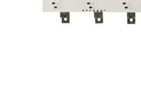
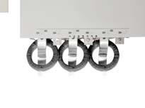
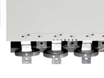
19 Installation 5.6 Power Terminations For personnel safety, the power terminals on models up to QLxxB0105D are protected by snap-off tabs. When using large cables, it may be necessary to break off these tabs. Some units use aluminium busbars. When connecting power terminations, we recommend cleaning the surface contact area thoroughly (using an emery or stainless steel brush) and using an appropriate jointing compound to prevent corrosion. Use only copper stranded or solid conductors, rated for 75 ºC or higher. QLxxB0023D~QLxxB0105D Cable size: Torx T20 x mm 2 (AWG 10-1/0) Flat 7 mm x mm (0.55 inch) Torque: 4 Nm (2.9 ft-lb) QLxxB0145D QLxxB0170D~QLxxB0220D QLxxB0255D 19 Nm (14.0 ft-lb) 38 Nm (28.0 ft-lb) 38 Nm (28.0 ft-lb) E A 8.5 mm (M8) 10.5 mm (M10) 11 mm (M10) B B B 19 mm 6 mm 19 mm QLxxB0350D~QLxxB0425D QLxxB0500D~QLxxB1000D QLxxX0255D 38 Nm (28.0 ft-lb) 38 Nm (28.0 ft-lb) 38 Nm (28.0 ft-lb) 6 mm 28 mm 5 mm 11 mm (M10) 11 mm (M10) 10.5 mm (M10) A B B 28 mm 6 mm 32 mm 13 mm 32 mm 6 mm 10.5 mm (M10) QLxxX0360D~QLxxX0930D QLxxX1200D~QLxxX1600D 38 Nm (28.0 ft-lb) 66 Nm (48.7 ft-lb) 12.5 mm (M12) B B 32 mm 13 mm 51 mm 16 mm 18 DET-812
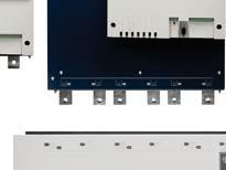
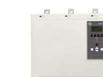
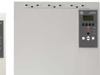
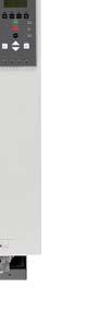
20 Local Local Remote Status Graphs Logs Start Ready Stop Run Reset Trip Menu Exit Enter RemoteInputs InputA Start Stop Reset Local Local Remote Status Graphs Logs Start Ready Stop Run Reset Trip Menu Exit Enter RemoteInputs InputA Start Stop Reset Local Local Remote Status Graphs Logs Start Ready Stop Run Reset Trip Menu Exit Enter RemoteInputs InputA Start Stop Reset Local Local Remote Status Graphs Logs Start Ready Stop Run Reset Trip Menu Exit Enter RemoteInputs InputA Start Stop Reset Local Local Remote Status Graphs Logs Start Ready Stop Run Reset Trip Menu Exit Enter RemoteInputs InputA Start Stop Reset ASTAT XL User Manual Installation 5.7 Power Input and Output Configurations Internally Bypassed Models (QLxxB0023D~QLxxB1000D) Models QLxxB0023D ~ QLxxB0220D have power inputs at the top of the unit and outputs at the bottom of the unit. Internally bypassed models QLxxB0255D ~ QLxxB0425D have output busbars at the bottom of the unit and input busbars at both the top and bottom of the unit. The AC supply can be connected 'Top in, Bottom out' or 'Bottom in, Bottom out'. Internally bypassed models QLxxB0500D ~ QLxxB1000D have input and output busbars at the top and bottom of the unit. The AC supply can be connected 'Top in, Bottom out', 'Top in, Top out', 'Bottom in, Bottom out' or 'Bottom in, Top out'. QLxxB0023D~ QLxxB0105D QLxxB0145D~ QLxxB0220D QLxxB0255D~ QLxxB0425D QLxxB0500D~ QLxxB1000D 1/L1 3/L2 5/L3 2/T1 4/T2 6/T3 1/L1, 3/L2, 5/L3 1/L1 3/L2 5/L3 1/L1 3/L2 5/L3 2/T1, 4/T2, 6/T3 2/T1 4/T2 6/T3 1/L1 3/L2 5/L3 2/T1 4/T2 6/T A 1/L1 3/L2 5/L3 2/T1 4/T2 6/T Non-bypassed Model - QLxxX0255D QLxxX0255D has dedicated bypass terminals at the bottom of the unit. The bypass terminals are T1B, T2B, T3B. 1/L1 3/L2 5/L A T1B T2B T3B 2/T1 4/T2 6/T Non-bypassed Models (QLxxX0360D~QLxxX1600D) QLxxX0360D~QLxxX1600D have dedicated bypass terminals, on the input busbars. The bypass terminals are L1B, L2B, L3B. The busbars on non-bypassed models QLxxX0360D ~ QLxxX1600D can be adjusted for top or bottom input and output as required. All units are manufactured top in/bottom out. For models QLxxX0360D ~ QLxxX1600D to be UL compliant, these must be mounted Top In, Bottom Out or Top Out, Bottom In. See UL Compliant Installation on page 14 for more information. 1/L1 3/L2 5/L3 (L1B L2B L3B) 2/T1 4/T2 6/T3 2/T1 4/T2 6/T3 1/L1 3/L2 5/L3 (L1B L2B L3B) D 2/T1 4/T2 6/T3 (L1B L2B L3B) 1/L1 3/L2 5/L3 (L1B L2B L3B) 1/L1 3/L2 5/L3 2/T1 4/T2 6/T3 DET
21 Installation 5.8 Schematic Diagrams Internally bypassed models 1/L1 2/T1 Non-bypassed models 1/L1 L1B * 2/T1 3/L2 4/T2 3/L2 L2B * 4/T2 5/L3 6/T3 5/L3 L3B * 6/T3 A4 PE A4 PE 24 VDC 200 ma A A5 A VDC 200 ma A A5 A B 1 Control voltage (model dependent) 54, 55 Start 2 Remote control inputs 56, 57 Stop 3 Motor thermistor input 58, 57 Reset 4 Relay outputs 53, 55 Programmable input A 40, 41 Analog output 13, 14 Relay output A 55, VDC output 21, 22, 24 Relay output B 33, 34 Relay output C B Different models require control voltage to different terminals: 1 (110~120 VAC) A5, A6 1 (220~240 VAC) A4, A6 2 (24 VAC/VDC) A5, A6 * QLxxX0255D current transformers are located on the output. Bypass terminals are labelled T1B, T2B and T3B. 20 DET-812
22 Power Circuits 6 Power Circuits 6.1 Motor Connection ASTAT XL soft starters can be connected to the motor in-line or inside delta (also called three-wire and six-wire connection). When connecting in inside delta, enter the motor full load current (FLC) for parameter 1A. The ASTAT XL will automatically detect whether the motor is connected in-line or inside delta and will calculate the correct inside delta current level Testing the Installation The ASTAT XL can be connected to a small motor for testing. During this test, the soft starter's control input and relay output protection settings can be tested. This test mode is not suitable for testing soft starting or soft stopping performance. The FLC of the test motor must be at least 2% of the soft starter's minimum FLC (see Minimum and Maximum Current Settings on page 11). When testing the soft starter with a small motor, set parameter 1A Motor Full Load Current to the minimum allowable value. Models which are internally bypassed do not require an external bypass contactor In-line installation, internally bypassed K1 F1 1/L1 3/L2 2/T1 4/T2 M 3 K1 F1 Main contactor (optional) Semiconductor fuses (optional) 5/L3 6/T3 E K1 DET
23 Power Circuits In-line installation, externally bypassed Non-bypassed models have dedicated bypass terminals, which allow the ASTAT XL to continue providing protection and monitoring functions even when bypassed via an external bypass contactor. The bypass contactor must be connected to the bypass terminals and controlled by a programmable output configured to Run (see parameters 7A~7I). K1 K2 F1 Main contactor (optional) Bypass contactor (external) Semiconductor fuses (optional) The bypass terminals on QLxxX0255D are T1B, T2B, T3B. QLxxX0360D ~ QLxxX1600D are L1B, L2B, L3B. The bypass terminals on The fuses can be installed on the input side if required In-line installation, non-bypassed K1 F1 1/L1 3/L2 2/T1 4/T2 M 3 K1 F1 Main contactor (optional) Semiconductor fuses (optional) 5/L3 6/T3 E K1 22 DET-812
24 Power Circuits Inside delta installation, internally bypassed K1 F1 1/L1 2/T1 U1(1) U2(4) K1 F1 Main contactor (strongly recommended) Semiconductor fuses (optional) 3/L2 4/T2 V1(2) W1(3) M 3 V2(5) W2(6) 5/L3 6/T3 E K1 CAUTION When connecting the ASTAT XL in inside delta configuration, always install a main contactor or shunt trip circuit breaker Inside delta installation, externally bypassed Non-bypassed models have dedicated bypass terminals, which allow the ASTAT XL to continue providing protection and monitoring functions even when bypassed via an external bypass contactor. The bypass contactor must be connected to the bypass terminals and controlled by a programmable output configured to Run (see parameters 7A~7I). K1 1/L1 K2 2/T1 F1 K1 K2 F1 Main contactor (strongly recommended) Bypass contactor (external) Semiconductor fuses (optional) L1B* 3/L2 L2B* 5/L3 L3B* E 4/T2 6/T V1(2) W1(3) U1(1) U2(4) M 3 V2(5) W2(6) 21 K1 24 K2 The bypass terminals on QLxxX0255D are T1B, T2B, T3B. QLxxX0360D ~ QLxxX1600D are L1B, L2B, L3B. The bypass terminals on The fuses can be installed on the input side if required. CAUTION When connecting the ASTAT XL in inside delta configuration, always install a main contactor or shunt trip circuit breaker. DET
25 Power Circuits Inside delta installation, non-bypassed K1 F1 1/L1 3/L2 2/T1 4/T2 V1(2) W1(3) U1(1) U2(4) M 3 V2(5) W2(6) K1 F1 Main contactor (strongly recommended) Semiconductor fuses (optional) 5/L3 6/T D 14 K1 CAUTION When connecting the ASTAT XL in inside delta configuration, always install a main contactor or shunt trip circuit breaker. 6.2 Bypass Contactor Some ASTAT XL soft starters are internally bypassed and do not require an external bypass contactor. Non-bypassed soft starters may be installed with an external bypass contactor. Select a contactor with an AC1 rating greater than or equal to the full load current rating of the connected motor. 6.3 Main Contactor A main contactor must be installed if the ASTAT XL is connected to the motor in inside delta format and is optional for in-line connection. Select a contactor with an AC3 rating greater than or equal to the full load current rating of the connected motor. 6.4 Circuit Breaker A shunt trip circuit breaker may be used instead of a main contactor to isolate the motor circuit in the event of a soft starter trip. The shunt trip mechanism must be powered from the supply side of the circuit breaker or from a separate control supply. 6.5 Power Factor Correction If power factor correction is used, a dedicated contactor should be used to switch in the capacitors. CAUTION Power factor correction capacitors must be connected to the input side of the soft starter. Connecting power factor correction capacitors to the output side will damage the soft starter. 6.6 Earth Terminals Earth terminals are located at the back of the soft starter. QLxxB0023D ~ QLxxB0105D have one terminal on the input side (top). QLxxB0145D ~ QLxxB1000D and QLxxX0255D ~ QLxxX1600D have two terminals, one on the input side (top) and one on the output side (bottom). 6.7 Power Supply Fuses Semiconductor fuses can be used for Type 2 coordination (according to IEC standard) and to reduce the risk of damage to SCRs from transient overload currents. HRC fuses (such as Ferraz/Mersen AJT fuses) can be used for Type 1 coordination according to IEC standard. CAUTION Adaptive Control controls the motor's speed profile, within the programmed time limit. This may result in a higher level of current than traditional control methods. For applications using Adaptive Control to soft stop the motor with stop times greater than 30 seconds, motor branch protection should be selected as follows: standard HRC line fuses: minimum 150% motor full load current motor rated line fuses: minimum rating 100/150% motor full load current motor control circuit breaker minimum long time setting: 150% motor full load current motor control circuit breaker minimum short time setting: 400% motor full load current for 30 seconds See Appendix 1: Fuse Selection Tables on page 69 for details. 24 DET-812
26 Operation 7 Operation 7.1 The Keypad Hand Hand Auto Exit Status Graph Start Stop Reset Alarm Logs Run Menu Enter Ready Alarm A 1 Four-line display for status and programming details. 2 HAND/AUTO: Toggle between Hand and Auto control (i.e. local/remote control mode) STATUS: Open the status displays and scroll between different status screens GRAPH: Open the performance graphs and scroll between different graph screens ALARM LOGS: Open the logs 3 Soft starter local control buttons: START: Start the motor STOP: Stop the motor RESET: Reset a trip (Hand mode only). 4 Status LEDs (see below for details) 5 Menu navigation buttons: EXIT: Exit the menu or parameter, or cancel a parameter change. ENTER: Enter a menu or parameter, or save a parameter change. : Scroll to the next or previous menu or parameter, change the setting of the current parameter or scroll through the status or graph screens. 6 Remote input LEDs. When on: INPUT A: Programmable input A is active START: The remote start input is active STOP: The remote stop input is active RESET: The remote reset input is active 7.2 Starter Status LEDs LED name On Flashing Ready The motor is stopped and the starter is ready to start. The motor is stopped and the starter is waiting for the Restart Delay (parameter 5A) or Motor Temperature Check (parameter 4F). Run The motor is in run state (receiving full The motor is starting or stopping. voltage). Alarm The starter has tripped. The starter is in warning state. Hand The starter is in Local control mode. Status The status screens are active. Graph The graph screens are active. The graph has been paused. Alarm Logs The logs menu is open. If the starter is in remote control mode, the Hand LED will be off. If all LEDs are off, the starter is not receiving control voltage. 7.3 Displays The keypad displays a wide range of performance information about the soft starter. The bottom half of the screen shows real-time information on current or motor power (as selected in parameter 10J). Use the STATUS button or and buttons to select the information shown on the top half of the screen. Starter status Motor temperature Current Motor power Last start information Date and time SCR conduction Screens shown here are with the default settings. DET
27 Operation Starter Status The starter status screen shows details of the starter's operating status, motor temperature and motor power. Ready M1 000% 000.0kW Programmable screen The ASTAT XL's user-programmable screen can be configured to show the most important information for the particular application. Use parameters 10B to 10E to select which information to display. Ready 0000 hrs Motor Temperature The temperature screen shows which motor data set is in use, and the temperature of both motors as a percentage of total thermal capacity. If the ASTAT XL is configured for use on one motor, the temperature for the secondary motor (M2) will always show 0%. Primary Motor Set M1 000% M2 000% Current The current screen shows real-time line current on each phase. Phase Currents 000.0A 000.0A 000.0A Motor Power The motor power screen shows motor power (kw, HP and kva) and power factor kW 0000HP 0000kVA pf Last Start Information The last start information screen shows details of the most recent successful start: start duration (seconds) maximum start current drawn (as a percentage of motor full load current) calculated rise in motor temperature Last start 010 s 350 % FLC Temp 5% Date and Time The date/time screen shows the current system date and time (24 hour format). For details on setting the date and time, see Set Date and Time on page SCR Conduction Bargraph The SCR conduction bargraph shows the level of conduction on each phase. L1 Cond L2 Cond L3 Cond Graphs The ASTAT XL can display real-time performance information for: current motor temperature motor kw motor kva motor power factor The newest information is displayed at the right hand edge of the screen. Older data is not stored. To access the graphs or to change which graph is shown, press the GRAPHS button. The graph can also be paused, to allow past performance to be analysed. To pause the graph, press and hold the GRAPHS button for more than 0.5 seconds. To unpause the graph, press the GRAPHS button again. 26 DET-812
28 Operation The ASTAT XL will not collect data while the graph is paused. When graphing resumes, a small gap will be shown between the old data and the new data. 7.4 Start, Stop and Reset Commands The soft starter can be controlled in three ways: using the buttons on the keypad via remote inputs via a serial communication link The HAND/AUTO button controls whether the ASTAT XL will respond to local control (via the keypad) or remote control (via the remote inputs). The ASTAT XL can also be set to allow local control only or remote control only, using parameter 6A Local/Remote. The Hand LED on the keypad is on when the soft starter is in local control mode and off when the soft starter is in remote control mode. The STOP button on the keypad is always enabled. Control via the fieldbus communication network is always enabled in local control mode, and can be enabled or disabled in remote control mode (parameter 6B Comms in Remote). Control via the serial communication network requires an optional communication module Using the Soft Starter to Control a Motor To soft start the motor, press the START button on the keypad or activate the Start remote input. The motor will start using the start mode selected in parameter 2A. To stop the motor, press the STOP button on the keypad or activate the Stop remote input. The motor will stop using the stop mode selected in parameter 2H. To reset a trip on the soft starter, press the RESET button on the keypad or activate the Reset remote input. To stop the motor with a coast to stop, regardless of the setting of parameter 2H Stop Mode, press the local STOP and RESET buttons at the same time. The soft starter will remove power from the motor and open the main contactor, and the motor will coast to stop. 7.5 Soft Start Methods Soft starters offer a variety of methods to control motor starting. Each soft start method uses a different primary control parameter Constant Current Constant current is the traditional form of soft starting, which raises the current from zero to a specified level and keeps the current stable at that level until the motor has accelerated. Constant current starting is ideal for applications where the start current must be kept below a particular level. 700% 3 Current (%motor full load current) 600% 500% 400% 300% 200% 100% 1 2 1: Initial current (parameter 2C) 2: Current limit (parameter 2B) 3: Full voltage current 10% 20% 30% 40% 50% 60% 70% 80% 90% 100% Rotor speed (% full speed) DET
29 Operation Current Ramp Current ramp soft starting raises the current from a specified starting level (1) to a maximum limit (3), over an extended period of time (2). Current ramp starting can be useful for applications where: the load can vary between starts (for example a conveyor which may start loaded or unloaded). Set the initial current (parameter 2C) to a level that will start the motor with a light load, and the current limit (parameter 2B) to a level that will start the motor with a heavy load. the load breaks away easily, but starting time needs to be extended (for example a centrifugal pump where pipeline pressure needs to build up slowly). the electricity supply is limited (for example a generator set), and a slower application of load will allow greater time for the supply to respond. 700% 4 Current (%motor full load current) 600% 500% 400% 300% 200% 100% 1: Initial current (parameter 2C) 2 2: Start ramp time (parameter 2D) 3 3: Current limit (parameter 2B) 4: Full voltage current 1 Time Adaptive Control for Starting In an adaptive control soft start, the ASTAT XL adjusts the current in order to start the motor within a specified time and using a selected acceleration profile. CAUTION Adaptive Control cannot start the motor faster than a direct on-line (DOL) start. If the start ramp time (parameter 2D) is shorter than the motor's DOL start time, starting current may reach DOL levels. Every application has a particular starting profile, based on characteristics of the load and the motor. Adaptive Control offers three different starting profiles, to suit the requirements of different applications. Selecting a profile that matches the inherent profile of the application can help smooth out acceleration across the full start time. Selecting a dramatically different Adaptive Control profile can somewhat neutralise the inherent profile. The ASTAT XL monitors the motor's performance during each start, to improve control for future soft starts Adaptive Control To use Adaptive Control to control starting performance: 1. Select Adaptive Control from the Start Mode menu (parameter 2A) 2. Set the desired Start Ramp Time (parameter 2D) 3. Select the desired Adaptive Start Profile (parameter 2J) 4. Set a start Current Limit (parameter 2B) sufficiently high to allow a successful start. The first Adaptive Control start will be a Constant Current start. This allows the ASTAT XL to learn the characteristics of the connected motor. This motor data is used by the ASTAT XL during subsequent Adaptive Control starts. Speed 100% 90% 80% 70% 60% 50% 40% 30% 20% 10% Time C Adaptive start profile (parameter 2J): 1. Early acceleration 2. Constant acceleration 3. Late acceleration 4. Start ramp time (parameter 2D) 28 DET-812
30 Operation How to Select the Adaptive Control Start Profile The best profile will depend on the exact details of each application. Some loads, such as submersible pumps, should not be run at slow speeds. An early acceleration profile will raise the speed quickly, then control acceleration through the rest of the start. Adaptive Control will control the load according to the programmed profile. Start current will vary according to the selected acceleration profile and the programmed start time. If replacing a motor connected to a ASTAT XL programmed for Adaptive Control starting or stopping, or if the starter has been tested on a different motor prior to actual installation, the starter will need to learn the characteristics of the new motor. The ASTAT XL will automatically re-learn the motor's characteristics if parameter 1A Motor Full Load Current or parameter 2L Adaptive Control Gain is changed. CAUTION Adaptive Control controls the motor's speed profile, within the programmed time limit. This may result in a higher level of current than traditional control methods Fine-tuning Adaptive Control If the motor does not start or stop smoothly, adjust the adaptive control gain (parameter 2L). The gain setting determines how much the ASTAT XL will adjust future adaptive control starts and stops, based on information from the previous start. The gain setting affects both starting and stopping performance. If the motor accelerates or decelerates too quickly at the end of a start or stop, increase the gain setting by 5%~10%. If the motor speed fluctuates during starting or stopping, decrease the gain setting slightly. Changing the gain setting resets the starter's adaptive control learning. The first start after changing the gain will use constant current Kickstart Kickstart provides a short boost of extra torque at the beginning of a start, and can be used in conjunction with current ramp or constant current starting. Kickstart can be useful to help start loads that require high breakaway torque but then accelerate easily (for example flywheel loads such as presses). Current (%motor full load current) : Kickstart level (parameter 2E) 2: Kickstart time (parameter 2F) 3: Initial current (parameter 2C) 4: Start ramp time (parameter 2D) 5: Current limit (parameter 2B) 6: Full voltage current Rotor speed (% full speed) 7.6 Stop Methods Soft starters offer a variety of methods for the control of motor stopping. Stop Method Performance Result Coast To Stop Natural load run down TVR Soft Stop Extended run down time Adaptive Control Extended run down time according to selected deceleration profile Brake Reduced run down time Soft starters are often used in pumping applications to eliminate the damaging effects of fluid hammer. Adaptive Control should be the preferred stop method for these applications. DET
31 Operation Coast to Stop Coast to stop lets the motor slow at its natural rate, with no control from the soft starter. The time required to stop will depend on the type of load TVR Soft Stop Timed voltage ramp reduces the voltage to the motor gradually over a defined time. The load may continue to run after the stop ramp is complete. Timed voltage ramp stopping can be useful for applications where the stop time needs to be extended, or to avoid transients on generator set supplies. 1 Voltage (% full voltage) 1: Stop time (parameter 2I) Time Adaptive Control for Stopping In an adaptive control soft stop, the ASTAT XL controls the current in order to stop the motor within a specified time and using a selected deceleration profile. Adaptive Control can be useful in extending the stopping time of low inertia loads. Adaptive control does not actively slow the motor down and will not stop the motor faster than a coast to stop. To shorten the stopping time of high inertia loads, use brake. CAUTION Adaptive Control controls the motor's speed profile, within the programmed time limit. This may result in a higher level of current than traditional control methods. Every application has a particular stopping profile, based on characteristics of the load and the motor. Adaptive Control offers three different stopping profiles. Choose the adaptive control profile that best matches your application requirements Adaptive Control To use Adaptive Control to control stopping performance: 1. Select Adaptive Control from the Stop Mode menu (parameter 2H) 2. Set the desired Stop Time (parameter 2I) 3. Select the required Adaptive Stop Profile (parameter 2K) Speed 100% 90% 80% 70% 60% 50% 40% 30% 20% 10% Time C Adaptive Control stop profile (parameter 2K): 1. Early deceleration 2. Constant deceleration 3. Late deceleration 4. Stop time (parameter 2I) 30 DET-812
32 Operation Pump stopping The hydraulic characteristics of pump systems vary considerably. This variation means the ideal deceleration profile and stop time will vary from application to application. The table provides guidelines on selecting between Adaptive Control deceleration profiles, but we recommend testing the three profiles to identify the best profile for the application. Adaptive Stop Profile Application Late Deceleration High head systems where even a small decrease in motor/pump speed results in a rapid transition between forward flow and reverse flow. Constant Deceleration Low to medium head, high flow applications where the fluid has high momentum. Early Deceleration Open pump systems where fluid must drain back through the pump without driving the pump in reverse. The first Adaptive Control stop will be a normal soft stop. This allows the ASTAT XL to learn the characteristics of the connected motor. This motor data is used by the ASTAT XL during subsequent Adaptive Control stops. Adaptive Control will control the load according to the programmed profile. Stopping current will vary according to the selected deceleration profile and stop time. If replacing a motor connected to a ASTAT XL programmed for Adaptive Control starting or stopping, or if the starter has been tested on a different motor prior to actual installation, the starter will need to learn the characteristics of the new motor. The ASTAT XL will automatically re-learn the motor's characteristics if parameter 1A Motor Full Load Current or parameter 2L Adaptive Control Gain is changed Brake Brake reduces the time required to stop the motor. During braking an increased noise level from the motor may be audible. This is a normal part of motor braking. When brake is selected, the ASTAT XL uses DC injection to slow the motor. ASTAT XL braking: Does not require the use of a DC brake contactor Controls all three phases so that the braking currents and associated heating are evenly distributed through the motor. CAUTION If the brake torque is set too high, the motor will stop before the end of the brake time and the motor will suffer unnecessary heating which could result in damage. Careful configuration is required to ensure safe operation of the starter and motor. A high brake torque setting can result in peak currents up to motor DOL being drawn while the motor is stopping. Ensure protection fuses installed in the motor branch circuit are selected appropriately. CAUTION Brake operation causes the motor to heat faster than the rate calculated by the motor thermal model. If you are using brake, install a motor thermistor or allow sufficient restart delay (parameter 5A). Braking has two stages: Pre-brake: provides an intermediate level of braking to slow motor speed to a point where full brake can be operated successfully (approximately 70% speed). Full brake: brake provides maximum braking torque but is ineffective at speeds greater than approximately 70%. DET
33 Operation To configure the ASTAT XL for brake operation: 1. Set parameter 2I for the desired stopping time duration (1). This is the total braking time and must be set sufficiently longer than the brake time (parameter 15H) to allow the pre-braking stage to reduce motor speed to approximately 70%. If the stop time is too short, braking will not be successful and the motor will coast to stop. 2. Set Brake Time (parameter 15H) to approximately one quarter of the programmed Stop Time. This sets the time for the Full Brake stage (2). 3. Adjust the Brake Torque (parameter 15G) so that the desired stopping performance is achieved. If set too low, the motor will not stop completely and will coast to stop by the end of the braking period. 100% Speed 75% 50% 25% 3 1: Stop time (parameter 2I) 2: Brake time (parameter 15H) 3: Coast to stop time 0% 1 2 Time CAUTION When using DC brake, the mains supply must be connected to the soft starter (input terminals L1, L2, L3) in positive phase sequence and parameter 4B Phase Sequence must be set to Positive Only. For loads which may vary between braking cycles, install a zero speed sensor to ensure that the soft starter ends DC braking when the motor stops. This avoids unnecessary heating of the motor. For more information on using the ASTAT XL with an external speed sensor (eg for applications with variable load during the braking cycle), see DC Brake with External Zero Speed Sensor on page Jog Operation Jog runs the motor at reduced speed, to allow alignment of the load or to assist servicing. The motor can be jogged in either forward or reverse direction. The maximum available torque for jog forward is approximately 50%~75% of motor full load torque (FLT) depending on the motor. The torque when the motor is jogged in reverse is approximately 25% to 50% of FLT. Parameter 15F Jog Torque controls how much of the maximum available jog torque the soft starter will apply to the motor. Setting parameter 15F above 50% may cause increased shaft vibration. 100% Available torque 90% 80% 70% 60% 50% 40% 30% 20% 10% 0% D 1. Motor FLT 2. Jog forward maximum torque 3. Jog reverse maximum torque 32 DET-812
34 Operation To activate jog operation, use a programmable input (parameter 6D). If any other command is received when jogging the starter will stop and await a new command. Soft start and soft stop are not available during jog operation. Jog is only available for the primary motor. CAUTION Slow speed running is not intended for continuous operation due to reduced motor cooling. Jog operation causes the motor to heat faster than the rate calculated by the motor thermal model. If you are using jog, install a motor thermistor or allow sufficient restart delay (parameter 5A) 7.8 Inside Delta Operation Adaptive Control, Jog, Brake and PowerThrough functions are not supported with inside delta (six-wire) operation. If these functions are programmed when the starter is connected inside delta the behaviour is as given below: Adaptive Control Start The starter performs a constant current start. Adaptive Control Stop The starter performs a TVR soft stop if parameter 2I Stop Time is >0 secs. If parameter 2I is set to 0 secs the starter performs a coast to stop. Jog The starter issues a warning with the error message Unsupported Option. Brake The starter performs a coast to stop. PowerThrough The starter trips with the error message Lx-Tx Shorted. When connected in inside delta, current imbalance is the only phase loss protection that is active during run. Do not disable current imbalance protection (parameter 4A) during inside delta operation. CAUTION Inside delta operation is only possible with mains voltage 600 VAC. DET
35 Programming Menu 8 Programming Menu The Programming Menu lets you view and change programmable parameters that control how the ASTAT XL operates. To open the Programming Menu, press the MENU/ENTER button while viewing the status or graph screens. To navigate through the Programming Menu: to scroll through parameter groups, press the or button. to open a submenu, press the ENTER button. to view the parameters in a group, press the ENTER button. to return to the previous level, press the EXIT button. to close the Programming Menu, press EXIT repeatedly or press the STATUS or GRAPHS button. To change a parameter value: scroll to the appropriate parameter in the Programming Menu and press ENTER to enter edit mode. to alter the parameter setting, use the and buttons. Pressing or once will increase or decrease the value by one unit. If the button is held for longer than five seconds, the value will increase or decrease at a faster rate. to save changes, press ENTER. The setting shown on the display will be saved and the keypad will return to the parameter list. to cancel changes, press EXIT. The keypad will ask for confirmation, then return to the parameter list without saving changes. You can access the Programming Menu at any time, including while the soft starter is running. Any changes to the start profile take effect immediately. The Programming Menu contains four sub-menus: Quick Setup Menu Provides access to quick setup options for common applications. Standard Menu The Standard Menu provides access to commonly used parameters, allowing you to configure the ASTAT XL to suit your application. Extended Menu The Extended Menu provides access to all the ASTAT XL's programmable parameters, allowing experienced users to take advantage of advanced features. Setup Tools Setup Tools includes maintenance options to configure the ASTAT XL's date and time or load a standard parameter set. 8.1 Quick Setup The Quick Setup Menu makes it easy to configure the ASTAT XL for common applications. The ASTAT XL selects the parameters relevant to the application and suggests a typical setting, and you can adjust each parameter to suit your exact requirements. Always set parameter 1A Motor Full Load Current to match the motor's nameplate full load current. The suggested value is the starter's minimum full load current. On the display, the highlighted values are suggested values and the values enclosed in a box are the loaded values. 34 DET-812
36 Programming Menu Application Parameter Suggested value Pump Centrifugal Motor Full Load Current Start Mode Adaptive Start Profile Start Ramp Time Stop Mode Adaptive Stop Profile Stop Time Model dependent Adaptive Control Early Acceleration 10 seconds Adaptive Control Late Deceleration 15 seconds Pump Submersible Fan Damped Fan Undamped Compressor Screw Compressor Recip Conveyor Crusher Rotary Crusher Jaw Motor Full Load Current Start Mode Adaptive Start Profile Start Ramp Time Stop Mode Adaptive Stop Profile Stop Time Motor Full Load Current Start Mode Current Limit Motor Full Load Current Start Mode Adaptive Start Profile Start Ramp Time Excess Start Time Locked Rotor Time Motor Full Load Current Start Mode Start Ramp Time Current Limit Motor Full Load Current Start Mode Start Ramp Time Current Limit Motor Full Load Current Start Mode Start Ramp Time Current Limit Stop Mode Adaptive Stop Profile Stop Time Motor Full Load Current Start Mode Start Ramp Time Current Limit Excess Start Time Locked Rotor Time Motor Full Load Current Start Mode Start Ramp Time Current Limit Excess Start Time Locked Rotor Time Model dependent Adaptive Control Early Acceleration 5 seconds Adaptive Control Late Deceleration 5 seconds Model dependent Constant Current 350% Model dependent Adaptive Control Constant Acceleration 20 seconds 30 seconds 20 seconds Model dependent Constant Current 5 seconds 400% Model dependent Constant Current 5 seconds 450% Model dependent Constant Current 5 seconds 400% Adaptive Control Constant Deceleration 10 seconds Model dependent Constant Current 10 seconds 400% 30 seconds 20 seconds Model dependent Constant Current 10 seconds 450% 40 seconds 30 seconds DET
37 Programming Menu 8.2 Standard Menu The standard menu provides access to commonly used parameters, allowing the user to configure the ASTAT XL as required for the application. 1 Motor Details 1A Motor Full Load Current Default Setting Model dependent 2 Primary Start/Stop 2A Start Mode Constant Current 2B Current Limit 350% 2C Initial Current 350% 2D Start Ramp Time 00:10 mm:ss 2G Excess Start Time 00:20 mm:ss 2H Stop Mode Coast To Stop 2I Stop Time 00:00 mm:ss 4 Protection Levels 4B Phase Sequence 4C Undercurrent 4D Instantaneous Overcurrent 4E Input A Trip 5 Protection Delays 5C Undercurrent Delay 5D Instantaneous Overcurrent Delay 5E Input A Trip Delay 5F Input A Initial Delay 6 Inputs 6D Input A Function 6E Input A Name 7 Relay Outputs 7A Relay A Function 7B Relay A On Delay 7C Relay A Off Delay 7D Relay B Function 7E Relay B On Delay 7F Relay B Off Delay 7G Relay C Function 7H Relay C On Delay 7I Relay C Off Delay 7J Low Current Flag 7K High Current Flag 7L Motor Temperature Flag 10 Display 10A Language 10B User Screen - Top Left 10C User Screen - Top Right 10D User Screen - Bottom Left 10E User Screen - Bottom Right 10J Display A or kw Any Sequence 20% FLC 400% FLC Always Active 00:05 mm:ss 00:00 mm:ss 00:00 mm:ss 00:00 mm:ss Motor Set Select Input Trip Main Contactor 00:00 mm:ss 00:00 mm:ss Run 00:00 mm:ss 00:00 mm:ss Trip 00:00 mm:ss 00:00 mm:ss 50% FLC 100% FLC 80% FLC English Starter State Blank Hours Run Blank Current 36 DET-812
38 Programming Menu 8.3 Extended Menu The Extended Menu provides access to all the ASTAT XL's programmable parameters. Default Setting 1 Motor Details 1A Motor Full Load Current Model dependent 1B Locked Rotor Time 00:10 mm:ss 1C Motor FLC-2 Model dependent 1D Locked Rotor Time-2 00:10 mm:ss 1E Dual Thermal Model Single 2 Primary Start/Stop 2A Start Mode Constant Current 2B Current Limit 350% FLC 2C Initial Current 350% FLC 2D Start Ramp Time 00:10 mm:ss 2E Kickstart Level 500% FLC 2F Kickstart Time 0 ms 2G Excess Start Time 00:20 mm:ss 2H Stop Mode Coast To Stop 2I Stop Time 00:00 mm:ss 2J Adaptive Start Profile Constant Acceleration 2K Adaptive Stop Profile Constant Deceleration 2L Adaptive Control Gain 75% 3 Secondary Start/Stop 3A Start Mode-2 Constant Current 3B Current Limit-2 350% FLC 3C Initial Current-2 350% FLC 3D Start Ramp-2 00:10 mm:ss 3E Kickstart Level-2 500% FLC 3F Kickstart Time-2 0 ms 3G Excess Start Time-2 00:20 mm:ss 3H Stop Mode-2 Coast To Stop 3I Stop Time-2 00:00 mm:ss 3J Adaptive Start Profile-2 Constant Acceleration 3K Adaptive Stop Profile-2 Constant Deceleration 3L Adaptive Control Gain-2 75% 4 Protection Levels 4A Current Imbalance 30% 4B Phase Sequence Any Sequence 4C Undercurrent 20% FLC 4D Instantaneous Overcurrent 400% FLC 4E Input A Trip Always Active 4F Motor Temperature Check Do Not Check 4G Frequency Check Start/Run 4H Frequency Variation ±5 Hz 5 Protection Delays 5A Restart Delay 00:10 mm:ss 5B Current Imbalance Delay 00:03 mm:ss 5C Undercurrent Delay 00:05 mm:ss 5D Instantaneous Overcurrent Delay 00:00 mm:ss 5E Input A Trip Delay 00:00 mm:ss 5F Input A Initial Delay 00:00 mm:ss 5G Frequency Delay 00:01 mm:ss DET
39 Programming Menu Default Setting 6 Inputs 6A Local/Remote LCL/RMT Anytime 6B Comms in Remote Enable Control in RMT 6C Remote Reset Logic Normally Closed (N/C) 6D Input A Function Motor Set Select 6E Input A Name Input Trip 7 Relay Outputs 7A Relay A Function Main Contactor 7B Relay A On Delay 00:00 mm:ss 7C Relay A Off Delay 00:00 mm:ss 7D Relay B Function Run 7E Relay B On Delay 00:00 mm:ss 7F Relay B Off Delay 00:00 mm:ss 7G Relay C Function Trip 7H Relay C On Delay 00:00 mm:ss 7I Relay C Off Delay 00:00 mm:ss 7J Low Current Flag 50% FLC 7K High Current Flag 100% FLC 7L Motor Temperature Flag 80% 8 Analog Output 8A Analog Output A Current (% FLC) 8B Analog A Scale 4-20 ma 8C Analog A Maximum Adjustment 100% 8D Analog A Minimum Adjustment 0% 9 Auto-Reset 9A Auto-Reset Action Do Not Auto-Reset 9B Maximum Resets 1 9C Reset Delay Groups A&B 00:05 mm:ss 9D Reset Delay Group C 5 minutes 10 Display 10A Language 10B User Screen - Top Left 10C User Screen - Top Right 10D User Screen - Bottom Left 10E User Screen - Bottom Right 10F Graph Timebase 10G Graph Maximum Adjustment 400% 10H Graph Minimum Adjustment 0% English Starter State Blank Hours Run Blank 10 seconds 10I Mains Reference Voltage 400 V 10J Display A or kw Current 15 Restricted 15A Access Code B Adjustment Lock Read & Write 15C Emergency Run Disable 15D Current Calibration 100% 15E Shorted SCR Action 3-Phase Control Only 15F Jog Torque 50% 15G Brake Torque 20% 15H Brake Time 00:01 mm:ss 15I Brake Torque-2 20% 15J Brake Time-2 00:01 mm:ss 38 DET-812
40 Programming Menu Default Setting 16 Protection Action 16A Motor Overload Trip Starter 16B Current Imbalance Trip Starter 16C Undercurrent Trip Starter 16D Instantaneous Overcurrent Trip Starter 16E Input A Trip Trip Starter 16F Frequency Trip Starter 16G Motor Thermistor Trip Starter 16H Excess Start Time Trip Starter 16I Starter Communication Trip Starter 16J Heatsink Overtemperature Trip Starter 16K Battery/Clock Trip Starter 16L Network Communication Trip Starter 16M Low Control Volts Trip Starter 8.4 Parameter Descriptions Motor Details Parameter 1B determines the trip current for motor overload protection. The default setting of parameter 1B provides Motor Overload Protection: Class 10, Trip Current 105% of FLA (full load amperage) or equivalent. 1A Motor FLC Range: Model dependent Description: Matches the starter to the connected motor's full load current. Set to the full load current (FLC) rating shown on the motor nameplate. 1B Locked Rotor Time Range: 0:01-2:00 (minutes:seconds) Default: 10 seconds Description: Sets the maximum length of time the motor can sustain locked rotor current from cold before reaching its maximum temperature. Set according to the motor datasheet. 1C Motor FLC-2 Range: Description: Model dependent Sets the secondary motor's full load current. 1D Locked Rotor Time-2 Range: 0:01-2:00 (minutes:seconds) Default: 10 seconds Description: Sets the maximum length of time the motor can sustain locked rotor current from cold before reaching its maximum temperature. Set according to the motor datasheet. 1E Dual Thermal Model Options: Single (default) Dual Description: Activates dual thermal modelling. The dual thermal model is required only if the ASTAT XL is controlling two physically separate motors. The second thermal model is only active if parameter 1E Dual Thermal Model is set to 'Dual' and the starter is using the secondary motor set (a programmable input is set to 'Motor Set Select' and the input is active). DET
41 Programming Menu Primary Start/Stop 2A Start Mode Options: Description: 2B Current Limit Constant Current (default) Adaptive Control Selects the soft start mode. Range: 100% - 600% FLC Default: 350% Description: Sets the current limit for constant current and current ramp soft starting, as a percentage of motor full load current. 2C Initial Current Range: 100% - 600% FLC Default: 350% Description: Sets the initial start current level for current ramp starting, as a percentage of motor full load current. Set so that the motor begins to accelerate immediately after a start is initiated. If current ramp starting is not required, set the initial current equal to the current limit. 2D Start Ramp Time Range: (seconds) Default: 10 seconds Description: Sets the total start time for an Adaptive Control start or the ramp time for current ramp starting (from the initial current to the current limit). 2E Kickstart Level Range: 100% - 700% FLC Default: 500% Description: Sets the level of the kickstart current. 2F Kickstart Time Range: milliseconds Default: 0000 milliseconds Description: Sets the kickstart duration. A setting of 0 disables kickstart. CAUTION Kickstart subjects the mechanical equipment to increased torque levels. Ensure the motor, load and couplings can handle the additional torque before using this feature. 2G Excess Start Time Excess start time is the maximum time the ASTAT XL will attempt to start the motor. If the motor does not transition to Run mode within the programmed limit, the starter will trip. Set for a period slightly longer than required for a normal healthy start. A setting of 0 disables excess start time protection. Range: 0:00-4:00 (minutes:seconds) Default: 20 seconds Description: Set as required. 2H Stop Mode Options: Description: Coast To Stop (default) TVR Soft Stop Adaptive Control Brake Selects the stop mode. 2I Stop Time Range: 0:00-4:00 (minutes:seconds) Default: 0 second Description: Sets the time for soft stopping the motor using timed voltage ramp or Adaptive Control. If a main contactor is installed, the contactor must remain closed until the end of the stop time. Use a programmable output configured to Run to control the main contactor. Sets the total stopping time when using brake. 40 DET-812
42 Programming Menu 2J Adaptive Start Profile Options: Description: 2K Adaptive Stop Profile Options: Description: 2L Adaptive Control Gain Early Acceleration Constant Acceleration (default) Late Acceleration Selects which profile the ASTAT XL will use for an Adaptive Control soft start. Early Deceleration Constant Deceleration (default) Late Deceleration Selects which profile the ASTAT XL will use for an Adaptive Control soft stop. Range: 1% - 200% Default: 75% Description: Adjusts the performance of Adaptive Control. This setting affects both starting and stopping control. We recommend leaving the gain setting at the default level unless performance is not satisfactory. If the motor accelerates or decelerates too quickly at the end of a start or stop, increase the gain setting by 5%~10%. If the motor speed fluctuates during starting or stopping, decrease the gain setting slightly Secondary Start/Stop See the Primary Start/Stop parameters for parameter details. 3A Start Mode-2 Options: Description: Constant Current (default) Adaptive Control Selects the soft start mode. 3B Current Limit-2 Range: 100% - 600% FLC Default: 350% Description: Sets the current limit for constant current and current ramp soft starting, as a percentage of motor full load current. 3C Initial Current-2 Range: 100% - 600% Default: 350% Description: Sets the initial start current level for current ramp starting, as a percentage of motor full load current. Set so that the motor begins to accelerate immediately after a start is initiated. If current ramp starting is not required, set the initial current equal to the current limit. 3D Start Ramp Time-2 Range: (seconds) Default: 10 seconds Description: Sets the total start time for an Adaptive Control start or the ramp time for current ramp starting (from the initial current to the current limit). 3E Kickstart Level-2 Range: 100% - 700% FLC Default: 500% Description: Sets the level of the kickstart current. 3F Kickstart Time-2 Range: (milliseconds) Default: 0000 milliseconds Description: Sets the kickstart duration. A setting of 0 disables kickstart. DET
43 Programming Menu 3G Excess Start Time-2 Range: 0:00-4:00 (minutes:seconds) Default: 20 seconds Description: Set as required. 3H Stop Mode-2 Options: Description: 3I Stop Time-2 Coast To Stop (default) TVR Soft Stop Adaptive Control Brake Selects the stop mode. Range: 0:00-4:00 (minutes:seconds) Default: 0 second Description: Sets the stop time. 3J Adaptive Start Profile-2 Options: Description: 3K Adaptive Stop Profile-2 Options: Description: 3L Adaptive Control Gain-2 Early Acceleration Constant Acceleration (default) Late Acceleration Selects which profile the ASTAT XL will use for an Adaptive Control soft start. Early Deceleration Constant Deceleration (default) Late Deceleration Selects which profile the ASTAT XL will use for an Adaptive Control soft stop. Range: 1% - 200% Default: 75% Description: Adjusts the performance of Adaptive Control. This setting affects both starting and stopping control Protection Levels 4A Current Imbalance Range: 10% - 50% Default: 30% Description: Sets the trip point for current imbalance protection. 4B Phase Sequence Options: Any Sequence (default) Positive Only Negative Only Description: Selects which phase sequences the soft starter will allow at a start. During its pre-start checks, the starter examines the sequence of the phases at its input terminals and trips if the actual sequence does not match the selected option. 4C Undercurrent Range: 0% - 100% Default: 20% Description: Sets the trip point for undercurrent protection, as a percentage of motor full load current. Set to a level between the motor's normal working range and the motor's magnetising (no load) current (typically 25% to 35% of full load current). A setting of 0% disables undercurrent protection. 4D Instantaneous Overcurrent Range: 80% - 600% FLC Default: 400% Description: Sets the trip point for instantaneous overcurrent protection, as a percentage of motor full load current. 42 DET-812
44 Programming Menu 4E Input A Trip Options: Always Active (default) A trip can occur at any time when the soft starter is receiving power. Operating Only A trip can occur while the soft starter is running, stopping or starting. Run Only A trip can only occur while the soft starter is running. Description: Selects when an input trip can occur. 4F Motor Temperature Check Options: Description: 4G Frequency Check Options: Description: Do Not Check (default) Check Selects whether the ASTAT XL will verify the motor has sufficient thermal capacity for a successful start. The soft starter compares the motor's calculated temperature with the temperature rise from the last motor start and only operates if the motor is cool enough to start successfully. Do Not Check Start Only Start/Run (default) Run Only Determines when and if the starter will monitor for a frequency trip. 4H Frequency Variation Options: ± 2 Hz ± 5 Hz (default) ± 10 Hz ± 15 Hz Description: Selects the soft starter's tolerance for frequency variation Protection Delays 5A Restart Delay Range: 00:01-60:00 (minutes:seconds) Default: 10 seconds Description: The ASTAT XL can be configured to force a delay between the end of a stop and the beginning of the next start. During the restart delay period, the display shows the time remaining before another start can be attempted. 5B Current Imbalance Delay Range: 0:00-4:00 (minutes:seconds) Default: 3 seconds Description: Slows the ASTAT XL's response to current imbalance, avoiding trips due to momentary fluctuations. 5C Undercurrent Delay Range: 0:00-4:00 (minutes:seconds) Default: 5 seconds Description: Slows the ASTAT XL's response to undercurrent, avoiding trips due to momentary fluctuations. 5D Instantaneous Overcurrent Delay Range: 0:00-1:00 (minutes:seconds) Default: 0 second Description: Slows the ASTAT XL's response to overcurrent, avoiding trips due to momentary overcurrent events. 5E Input A Trip Delay Range: 0:00-4:00 (minutes:seconds) Default: 0 second Description: Sets a delay between the input activating and the soft starter tripping. DET
45 Programming Menu 5F Input A Initial Delay Range: 00:00-30:00 (minutes:seconds) Default: 0 second Description: Sets a delay before an input trip can occur. The initial delay is counted from the time a start signal is received. The state of the input is ignored until the initial delay has elapsed. 5G Frequency Delay Range: 0:01-4:00 (minutes:seconds) Default: 1 second Description: Slows the ASTAT XL's response to frequency disturbances, avoiding trips due to momentary fluctuations Inputs 6A Local/Remote Options: LCL/RMT Anytime HAND/AUTO button is always enabled. LCL/RMT When Off HAND/AUTO button is enabled when the starter is off. Local Control Only All remote inputs are disabled. Remote Control Only Local control buttons (START, RESET, HAND/AUTO) are disabled. Description: Selects when the HAND/AUTO button can be used to switch between local and remote control, and enables or disables the local control buttons and remote control inputs. The STOP button on the keypad is always enabled. 6B Comms in Remote Options: Description: Disable Control in RMT Enable Control in RMT (default) Selects whether the starter will accept Start and Stop commands from the serial communication network when in Remote mode. The Reset and Local/Remote Control commands are always enabled. 6C Remote Reset Logic Options: Normally Closed (default) Normally Open Description: Selects whether the ASTAT XL's remote reset input (terminals 58, 57) is normally open or normally closed. 6D Input A Function Options: Motor Set Select (default) The ASTAT XL can be configured with two separate sets of motor data. To use the secondary motor data, parameter 6D must be set to 'Motor Set Select' and 53, 55 must be closed when a start command is given. The ASTAT XL checks which motor data to use at a start, and will use that motor data for the entire start/stop cycle. Input Trip (N/O) Input A can be used to trip the soft starter. When parameter 6D is set to Input Trip (N/O), a closed circuit across 53, 55 trips the soft starter. Input Trip (N/C) When parameter 6D is set to Input Trip (N/C), an open circuit across 53, 55 trips the soft starter. 44 DET-812
46 Programming Menu Local/Remote Select Emergency Run Input A can be used to select between local and remote control, instead of using the HAND/AUTO button on the keypad. When the input is open, the starter is in local mode and can be controlled via the keypad. When the input is closed, the starter is in remote mode. The START and HAND/AUTO buttons are disabled, and the soft starter will ignore any Local/Remote select command from the serial communications network. To use Input A to select between local and remote control, parameter 6A must be set to 'LCL/RMT Anytime' or 'LCL/RMT When Off'. In emergency run the soft starter continues to run until stopped, ignoring all trips and warnings (see parameter 15C for details). Closing the circuit across 53, 55 activates emergency run. Opening the circuit ends emergency run and the ASTAT XL stops the motor. Starter Disable The ASTAT XL can be disabled via the control inputs. An open circuit across 53, 55 will disable the starter. The ASTAT XL will not respond to start commands. If running, the soft starter will allow the motor to coast to stop, ignoring the soft stop mode set in parameter 2H. Jog Forward Activates jog operation in a forward direction (will operate only in Remote mode). Jog Reverse Activates jog operation in reverse direction (will operate only in Remote mode). Description: Selects the function of Input A. 6E Input A Name Options: Input Trip (default) No Flow Low Pressure Starter Disable High Pressure Controller Pump Fault PLC Low Level Vibration Alarm High Level Description: Selects a message for the keypad to display when Input A is active Relay Outputs 7A Relay A Function Options: Off Relay A is not used. Main Contactor (default) The relay closes when the ASTAT XL receives a start command, and remains closed as long as the motor is receiving voltage. Run The relay closes when the starter changes to run state. Trip The relay closes when the starter trips (see parameter 16A to 16M). Warning The relay closes when the starter issues a warning (see parameter 16A to 16M). Low Current Flag The relay closes when the low current flag activates while the motor is running (see parameter 7J Low Current Flag). High Current Flag The relay closes when the high current flag activates while the motor is running (see parameter 7K High Current Flag). Motor Temperature Flag The relay closes when the motor temperature flag activates (see parameter 7L Motor Temperature Flag). Description: Selects the function of Relay A (normally open). DET
47 Programming Menu 7B, 7C Relay A Delays The ASTAT XL can be configured to wait before opening or closing Relay A. Parameter 7B Relay A On Delay Range: 0:00-5:00 (minutes:seconds) Default: 0 second Description: Sets the delay for closing Relay A. Parameter 7C Relay A Off Delay Range: 0:00-5:00 (minutes:seconds) Default: 0 second Description: Sets the delay for re-opening Relay A. 7D~7I Output Relays B & C Parameters 7D~7I configure the operation of Relays B and C in the same way as parameters 7A~7C configure Relay A. See Relay A for details. Relay B is a changeover relay. 7D Relay B Function Default: Run 7E Relay B On Delay 7F Relay B Off Delay Relay C is normally open. 7G Relay C Function Default: Trip 7H Relay C On Delay 7I Relay C Off Delay 7J, 7K Low Current Flag and High Current Flag The ASTAT XL has low and high current flags to give early warning of abnormal operation. The current flags can be configured to indicate an abnormal current level during operation, between the normal operating level and the undercurrent or instantaneous overcurrent trip levels. The flags can signal the situation to external equipment via one of the programmable outputs. The flags clear when the current returns within the normal operating range by 10% of the programmed flag value. Parameter 7J Low Current Flag Range: 1% - 100% FLC Default: 50% Description: Sets the level at which the low current flag operates, as a percentage of motor full load current. Parameter 7K High Current Flag Range: 50% - 600% FLC Default: 100% Description: Sets the level at which the high current flag operates, as a percentage of motor full load current. 7L Motor Temperature Flag The ASTAT XL has a motor temperature flag to give early warning of abnormal operation. The flag can indicate that the motor is operating above its normal operating temperature but lower than the overload limit. The flag can signal the situation to external equipment via one of the programmable outputs. Range: 0% - 160% Default: 80% Description: Sets the level at which the motor temperature flag operates, as a percentage of the motor's thermal capacity. 46 DET-812
48 Programming Menu Analog Output The ASTAT XL has an analog output, which can be connected to associated equipment to monitor motor performance. 8A Analog Output A Options: Current (% FLC) (default) Motor Temp (%) Motor kw (%) Motor kva (%) Motor pf Current as a percentage of motor full load current. Motor temperature as a percentage of the motor's thermal capacity. Measured motor kilowatts, as a percentage of maximum kw. Measured motor kilovolt amperes, as a percentage of maximum kva. Motor power factor, measured by the soft starter. Description: 8B Analog A Scale Range: Description: Measured motor kw: 3 x average current x mains reference voltage x measured power factor Maximum motor kw: 3 x motor FLC x mains reference voltage. Power factor is assumed to be 1 Measured motor kva: 3 x average current x mains reference voltage Maximum motor kva: 3 x motor FLC x mains reference voltage Selects which information will be reported via the analog output ma 4-20 ma (default) Selects the range of the analog output. 8C Analog A Maximum Range: 0% - 600% Default: 100% Description: Calibrates the upper limit of the analog output to match the signal measured on an external current measuring device. 8D Analog A Minimum Range: 0% - 600% Default: 0% Description: Calibrates the lower limit of the analog output to match the signal measured on an external current measuring device Auto-Reset The ASTAT XL can be programmed to automatically reset certain trips, which can help minimise operating downtime. Trips are divided into three categories for auto-reset, depending on the risk to the soft starter: Group A Current imbalance Phase Loss Power loss Frequency B Undercurrent Instantaneous overcurrent Input A Trip C Motor overload Motor thermistor Heatsink Overtemperature Other trips cannot be automatically reset. This function is ideal for remote installations using 2-wire control in Auto mode. If the 2-wire start signal is present after an auto-reset, the ASTAT XL will restart. DET
49 Programming Menu 9A Auto-Reset Action Options: Description: 9B Maximum Resets Do Not Auto-Reset (default) Reset Group A Reset Group A & B Reset Group A, B & C Selects which trips can be auto-reset. Range: 1-5 Default: 1 Description: Sets how many times the soft starter will auto-reset, if it continues to trip. The reset counter increases by one each time the soft starter auto-resets, and decreases by one after each successful start/stop cycle. If the starter is manually reset, the resets counter will return to zero. 9C Reset Delay Groups A&B Range: 00:05-15:00 (minutes:seconds) Default: 5 seconds Description: Sets the delay before resetting Group A and Group B trips. 9D Reset Delay Group C Range: 5-60 (minutes) Default: 5 minutes Description: Sets the delay before resetting Group C trips Display 10A Language Options: English (default) Português Chinese Français Español Italiano Deutsch Russian Description: Selects which language the keypad will use to display messages and feedback. 10B, 10C, 10D, 10E User-Programmable Screen Options: Blank Displays no data in the selected area, allowing long messages to be shown without overlapping. Starter State The starter's operating state (starting, running, stopping or tripped). Only available for top left and bottom left positions on the screen. Motor Current The average current measured on three phases. Motor pf The motor's power factor, measured by the soft starter. Mains Frequency The average frequency measured on three phases. Motor kw The motor's running power in kilowatts. Motor HP The motor's running power in horsepower. Motor Temp The motor's temperature, calculated by the thermal model. kwh The number of kilowatt hours the motor has run via the soft starter. Hours Run The number of hours the motor has run via the soft starter. Description: Selects which information will be displayed on the programmable monitoring screen. 10B User Screen - Top Left Default: Starter State 10C User Screen - Top Right Default: Blank 10D User Screen - Bottom Left Default: Hours Run 10E User Screen - Bottom Right Default: Blank 48 DET-812
50 Programming Menu 10F Graph Timebase Options: 10 seconds (default) 30 seconds 1 minute 5 minutes 10 minutes 30 minutes 1 hour Description: Sets the graph time scale. The graph will progressively replace the old data with new data. 10G Graph Maximum Range: 0% 600% Default: 400% Description: Adjusts the upper limit of the performance graph. 10H Graph Minimum Range: 0% 600% Default: 0% Description: Adjusts the lower limit of the performance graph. 10I Mains Reference Voltage Range: V Default: 400 V Description: Sets the nominal mains voltage for the keypad's monitoring functions. This is used to calculate motor kilowatts and kilovolt amperes (kva) but does not affect the ASTAT XL's motor control or protection. 10J Display A or kw Options: Current (default) Motor kw Description: Selects whether the ASTAT XL will display current (amperes) or motor kilowatts on the main monitoring screen Restricted 15A Access Code Range: Default: 0000 Description: Sets the access code to control access to restricted sections of the menus. Use the EXIT and ENTER buttons to select which digit to alter and use the and buttons to change the value. In the event of a lost access code, contact your supplier for a master access code that allows you to re-program a new access code. 15B Adjustment Lock Options: Read & Write (default) Allows users to alter parameter values in the Programming Menu. Read Only Prevents users altering parameter values in the Programming Menu. Parameter values can still be viewed. Description: Selects whether the keypad will allow parameters to be changed via the Programming Menu. 15C Emergency Run Options: Disable (default) Enable Description: Selects whether the soft starter will permit emergency run operation. In emergency run, the soft starter will start (if not already running) and continue to operate until emergency run ends, ignoring stop commands and trips. Emergency run is controlled using a programmable input. CAUTION Continued use of Emergency Run is not recommended. Emergency Run may compromise the starter life as all protections and trips are disabled. Using the starter in 'Emergency Run' mode will void the product warranty. DET
51 Programming Menu 15D Current Calibration Range: 85% - 115% Default: 100% Description: Calibrates the soft starter's current monitoring circuits to match an external current metering device. Use the following formula to determine the necessary adjustment: Calibration (%) = Current shown on ASTAT XL display Current measured by external device eg 102% = 66A 65A This adjustment affects all current-based functions and protections. 15E Shorted SCR Action Options: 3-Phase Control Only (default) PowerThrough Description: Selects whether the soft starter will allow PowerThrough operation, if the soft starter is damaged on one phase. The soft starter will use two-phase control, allowing the motor to continue operating in critical applications. PowerThrough can only operate with internally bypassed soft starters. PowerThrough is only available with in-line installations. If the starter is installed inside delta, PowerThrough will not operate. PowerThrough remains active until '3-Phase Control Only' is reselected. A shorted SCR or a short within the bypass contactor will trip the starter on Lx-Tx shorted. If PowerThrough is enabled, the trip can be reset and subsequent starts will use PowerThrough two-phase control; however not all features will be available. The trip LED will flash and the display will indicate 2 Phase - Damaged SCR'. CAUTION PowerThrough uses a two-phase soft start technology and additional care is required when sizing circuit breakers and protection. Contact your local supplier for assistance. PowerThrough remains active until '3-Phase Control Only' is reselected. PowerThrough operation does not support Adaptive Control soft starting or soft stopping. In PowerThrough, the ASTAT XL will automatically select constant current soft starting and timed voltage ramp soft stopping. If PowerThrough is enabled, parameters 2C and 2B must be set appropriately. PowerThrough can only operate with internally bypassed soft starters. PowerThrough is only available with in-line installations. If the starter is installed inside delta, PowerThrough will not operate. The starter will trip on Lx-Tx Shorted on the first start attempt after control power is applied. PowerThrough will not operate if control power is cycled between starts. 15F Jog Torque The ASTAT XL can jog the motor at a reduced speed, which allows precise positioning of belts and flywheels. Jog can be used for either forward or reverse operation. Range: 20% - 100% Default: 50% Description: Sets the current limit for jog operation. 15G Brake Torque Range: 20% - 100% Default: 20% Description: Sets the amount of brake torque the ASTAT XL will use to slow the motor. 50 DET-812
52 < ASTAT XL User Manual Programming Menu 15H Brake Time Range: 1-30 (seconds) Default: 1 second Description: Sets the duration for DC injection during a braking stop. Parameter 15H is used in conjunction with parameter 2I. See Brake for details. 15I Brake Torque-2 Range: 20% - 100% Default: 20% Description: Sets the amount of brake torque the ASTAT XL will use to slow the motor. 15J Brake Time-2 Range: 1-30 (seconds) Default: 1 second Description: Sets the duration for DC injection during a braking stop Protection Action CAUTION Defeating the protection may compromise the starter and motor, and should only be done in the case of emergency. 16A~16M Protection Action Options: Trip Starter (default) Warn and Log Log Only Description: Selects the soft starter's response to each protection. 16A Motor Overload 16B Current Imbalance 16C Undercurrent 16D Instantaneous Overcurrent 16E Input A Trip 16F Frequency 16G Motor Thermistor 16H Excess Start Time 16I Starter Communication 16J Heatsink Overtemperature 16K Battery/Clock 16L Network Communication 16M Low Control Volts 8.5 Adjustment Lock You can lock the Programming Menu to prevent users from altering parameter settings. The adjustment lock can be turned on and off using parameter 15B. To lock the programming menu: 1. Open the Programming Menu. 2. Open the Extended Menu. 3. Select 'Restricted'. 4. Enter the Access Code. 5. Select parameter 15B Adjustment Lock 6. Select and store 'Read Only'. If a user attempts to change a parameter value when the adjustment lock is active, an error message is displayed: Access Denied Adj Lock is On DET
53 Programming Menu 8.6 Access Code Critical parameters (parameter group 15 and higher) are protected by a four-digit security access code, preventing unauthorised users from viewing or modifying parameter settings. When a user attempts to enter a restricted parameter group, the keypad prompts for an access code. The access code is requested once for the programming session, and authorisation continues until the user closes the menu. To enter the access code, use the EXIT and ENTER buttons to select a digit, and the and buttons to change the value. When all four digits match your access code, press ENTER. The keypad will display an acknowledgement message before continuing. Enter Access Code 0### ENTER Access Allowed SUPERVISOR To change the access code, use parameter 15A. The default access code is Setup Tools Setup Tools includes maintenance options to configure the ASTAT XL's date and time, reset the thermal models or load a standard parameter set. To access the Setup Tools, open the Programming Menu then select Setup Tools Set Date and Time To set the date and time: 1. Open the Setup Tools. 2. Scroll to the date/time screen. 3. Press the ENTER button to enter edit mode. 4. Press the ENTER and EXIT buttons to select which part of the date or time to edit. 5. Use the and buttons to change the value. 6. To save changes, press the ENTER button. The ASTAT XL will confirm the changes. To cancel changes, press the EXIT button Load/Save Settings The Load/Save Settings menu requires an access code and allows users to: Load the ASTAT XL's parameters with default values Reload previously saved parameter settings from an internal file Save the current parameter settings to an internal file In addition to the factory default values file, the ASTAT XL can store two user-defined parameter files. These files contain default values until a user file is saved. To load or save parameter settings: 1. Open the Setup Tools. 2. Scroll to Load/Save Settings and press the ENTER button. 3. Scroll to the required function and press the ENTER button. 4. At the confirmation prompt, select YES to confirm or NO to cancel and then ENTER to load/save the selection. When the action has been completed, the screen will briefly display a confirmation message, then return to the status screens. Load/Save Settings Load Defaults Load User Set 1 Load User Set 2 Load Defaults No Yes 52 DET-812
54 Programming Menu Reset Thermal Models This function is protected by the security access code. The ASTAT XL's advanced thermal modelling software constantly monitors the motor's performance. This allows the ASTAT XL to calculate the motor's temperature and ability to start successfully at any time. If the ASTAT XL is configured for use on two motors, each motor's temperature is modelled separately. The thermal model for the active motor can be reset if required. 1. Open the Setup Tools. 2. Scroll to Reset Thermal Models and press ENTER. Reset Thermal Models M1 X% M2 X% ENTER to Reset 3. Use to select Reset and press ENTER to confirm. Do Not Reset Reset 4. When the thermal model has been reset, the screen will display a confirmation message then return to the previous screen. CAUTION Resetting the motor thermal model may compromise motor life and should only be done in the case of emergency. DET
55 Logs Menu 9 Logs Menu The Logs Menu provides information on events, trips and starter performance. Press the ALARM LOGS button to open the Logs Menu. To navigate through the Logs Menu: to open a log, press the ENTER button. to scroll through the entries in each log, press the and buttons. to view details of a log entry, press the ENTER button. to return to the previous level, press the EXIT button. to close the Logs Menu, press ALARM LOGS. 9.1 Trip Log The Trip Log stores details of the eight most recent trips, including the date and time the trip happened. Trip 1 is the most recent and trip 8 is the oldest stored trip. To open the Trip Log: 1. Open the Logs Menu. 2. Scroll to Trip Log and press ENTER. 3. Use the and buttons to select a trip to view, and press ENTER to display details. To close the log and return to the main display, press ALARM LOGS. 9.2 Event Log The Event Log stores time-stamped details of the starter's 99 most recent events (actions, warnings and trips), including the date and time of the event. Event 1 is the most recent and event 99 is the oldest stored event. To open the Event Log: 1. Open the Logs Menu. 2. Scroll to Event Log and press ENTER. 3. Use the and buttons to select an event to view, and press ENTER to display details. To close the log and return to the main display, press ALARM LOGS. 9.3 Performance Counters The performance counters store statistics on the starter's operation: Hours run (lifetime and since counter last reset) Number of starts (lifetime and since counter last reset) Motor kwh (lifetime and since counter last reset) Number of times the thermal model has been reset To view the counters: 1. Open the Logs Menu. 2. Scroll to counters and press ENTER. 3. Use the and buttons to scroll through the counters. Press ENTER to view details. 4. To reset a counter, press ENTER then use the and buttons to select Reset/Do Not Reset. Press ENTER to confirm the action. To close the counter and return to the Logs Menu, press ENTER. The reset counters function is protected by the access code. 54 DET-812
56 Application Examples 10 Application Examples 10.1 Installation with Main Contactor The ASTAT XL is installed with a main contactor (AC3 rated). Control voltage must be supplied from the input side of the contactor. The main contactor is controlled by the ASTAT XL Main Contactor output, which by default is assigned to Output Relay A (terminals 13, 14). K1 F1 1/L1 2/T1 1 3/L2 4/T2 2 5/L3 E A4 A5 A6 3 6/T K1 1 Three-phase supply 2 Motor terminals 3 Control voltage (model dependent) 4 Remote control inputs 5 Motor thermistor input 6 Relay outputs K1 Main contactor F1 Semiconductor fuses (optional) 13, 14 Relay output A 21, 22, 24 Relay output B 33, 34 Relay output C B Parameter settings: Parameter 7A Relay A Function Select 'Main Contactor' - assigns the Main Contactor function to Relay Output A (default setting) DET
57 Application Examples 10.2 Installation with Bypass Contactor The ASTAT XL is installed with a bypass contactor (AC1 rated). The bypass contactor is controlled by the ASTAT XL Run Output which by default is assigned to Output Relay B (terminals 21, 22, 24). K1 F1 1/L1 2/T1 L1B 1 3/L2 4/T2 2 L2B 5/L3 6/T3 L3B E A Three-phase supply 2 Motor terminals 3 Control voltage (model dependent) 4 Remote control inputs 5 Motor thermistor input 6 Relay outputs K1 Bypass contactor (external) F1 Semiconductor fuses (optional) 13, 14 Relay output A 21, 22, 24 Relay output B 33, 34 Relay output C A5 A K Parameter settings: Parameter 7D Relay B Function Select 'Run' - assigns the run output function to Relay Output B (default value) B 56 DET-812
58 Application Examples 10.3 Emergency Run Operation In normal operation the ASTAT XL is controlled via a remote two-wire signal (terminals 56, 57). Emergency Run is controlled by a two-wire circuit connected to Input A (terminals 53, 55). Closing Input A causes the ASTAT XL to run the motor and ignore certain trip conditions. K1 F1 1/L1 2/T /L2 5/L3 E A4 A5 A6 3 4/T2 6/T Three-phase supply 2 Motor terminals 3 Control voltage (model dependent) 4 Remote control inputs 5 Motor thermistor input 6 Relay outputs S1 Start/stop contact S2 Reset contact S3 Emergency Run Contact 13, 14 Relay output A 21, 22, 24 Relay output B 33, 34 Relay output C S S S Parameter settings: Parameter 6D Input A Function Select 'Emergency Run' - assigns Input A for Emergency Run function. Parameter 15C Emergency Run Select 'Enable' - Enables Emergency Run mode B Although the Emergency Run satisfies the functionality requirements of Fire Mode, GE does not recommend its use in situations that require testing and/or compliance with specific standards as it is not certified. DET
59 Application Examples 10.4 Auxiliary Trip Circuit In normal operation the ASTAT XL is controlled via a remote two-wire signal (terminals 56, 57). Input A (terminals 53, 55) is connected to an external trip circuit (such as a low pressure alarm switch for a pumping system). When the external circuit activates, the soft starter trips, which stops the motor. K1 F1 1/L1 2/T /L2 5/L3 E A4 A5 A /T2 6/T Three-phase supply 2 Motor terminals 3 Control voltage (model dependent) 4 Remote control inputs 5 Motor thermistor input 6 Relay outputs S1 Start/stop contact S2 Reset contact S3 Auxiliary trip contact 13, 14 Relay output A 21, 22, 24 Relay output B 33, 34 Relay output C S S S B Parameter settings: Parameter 6D Input A Function Select 'Input Trip (N/O)'. Assigns the Input A to Auxiliary Trip (N/O) function. Parameter 6E Input A Name Select a name, eg Low Pressure. Assigns a name to Input A. Parameter 4E Input A Trip Set as required. For example, 'Run Only' limits the input trip to when the soft starter is running only. Parameter 5E Input A Trip Delay Set as required. Sets a delay between the input activating and the soft starter tripping. Parameter 5F Input A Initial Delay Set at around 120 seconds. Limits operation of the input trip to 120 seconds after the start signal. This allows time for pressure to build up in the piping before the low pressure input becomes active. 58 DET-812
60 Application Examples 10.5 DC Brake with External Zero Speed Sensor For loads which may vary between braking cycles, there are benefits in using an external zero-speed sensor to interface with the ASTAT XL for brake shut-off. This control method ensures that the ASTAT XL braking will always shut off when the motor has reached a standstill, thus avoiding unnecessary motor heating. The following schematic diagram shows how you can use a zero-speed sensor with the ASTAT XL to turn the brake function off at motor standstill. The zero-speed sensor (A2) is often referred to as an under-speed detector. Its internal contact is open at zero-speed and closed at any speed above zero-speed. Once the motor has reached a standstill, 53, 55 will open and the starter will be disabled. When the next start command is given (ie next application of K10), 53, 55 closes and the ASTAT XL is enabled. The ASTAT XL must be operated in remote mode and parameter 6D Input A Function must be set to 'Starter Disable'. L1 L2 L3 N E -F1 -K10 -A2 L1 L2 L3 E A4 A5 A T1 T2 T K10 -K C -K11 -K10 T1 T2 T3 M 3 -K10 -K11 1 Control voltage A Off (Ready) 54, 55 Start B Start 56, 57 Stop C Run 58, 57 Reset D Stop 2 Motor terminals E Zero speed 3 Three-phase supply 5 Start signal (2, 3, or 4-wire) 4 Starter Disable (shown on starter display) 6 Zero speed sensor For details on configuring DC Brake, see Brake (on page 31). CAUTION When using DC brake, the mains supply must be connected to the soft starter (input terminals L1, L2, L3) in positive phase sequence and parameter 4B Phase Sequence must be set to Positive Only. DET
61 Application Examples 10.6 Soft Braking For applications with high inertia and/or a variable load, the ASTAT XL can be configured for soft braking. In this application the ASTAT XL is employed with forward run and braking contactors. When the ASTAT XL receives a start signal (pushbutton S1), it closes the forward run contactor (K1) and controls the motor according to the programmed primary motor settings. When the ASTAT XL receives a stop signal (pushbutton S2), it opens the forward run contactor (K1) and closes the braking contactor (K2) after a delay of approximately 2-3 seconds (K1T). K12 is also closed to activate the secondary motor settings, which should be user programmed for the desired stopping performance characteristics. When motor speed approaches zero, the zero speed sensor (A2) stops the soft starter and opens the braking contactor (K2) Control voltage (model dependent) A2 Zero speed sensor 2 Remote control inputs K10 Run relay 3 Motor thermistor input K11 Start relay 4 Relay outputs K12 Brake relay 5 Three-phase supply K13 Zero speed sensor relay 6 Motor terminals K1 Line contactor (Run) K2 Line contactor (Brake) K1T Run delay timer K2T Brake delay timer K3T Zero speed sensor delay timer S1 Start contact S2 Stop contact S3 Reset contact Parameter settings: Parameter 6D Input A Function (terminals 53, 55) Select 'Motor Set Select' - assigns Input A for Motor set selection. Set starting performance characteristics using the primary motor set. Set braking performance characteristics using the secondary motor settings. Parameter 7G Relay C Function Select 'Trip' - assigns Trip function to Relay Output C. If the ASTAT XL trips on supply frequency (parameter 16F Frequency) when the braking contactor K2 opens, modify the frequency protection settings. 60 DET-812
62 Application Examples 10.7 Two Speed Motor The ASTAT XL can be configured for control of dual speed Dahlander type motors, using a high speed contactor (K1), low speed contactor (K2) and a star contactor (K3). Pole Amplitude Modulated (PAM) motors alter the speed by effectively changing the stator frequency using external winding configuration. Soft starters are not suitable for use with this type of two-speed motor. When the soft starter receives a high speed start signal, it closes the high speed contactor (K1) and star contactor (K3), then controls the motor according to the primary motor settings. When the soft starter receives a low speed start signal, it closes the low speed contactor (K2). This closes Input A and the ASTAT XL controls the motor according to the secondary motor settings. K3 T4 T5 4 1/L1 3/L2 5/L3 A4 2/T1 4/T2 6/T3 E K2 K1 T6 T1 T2 T3 5 A5 A6 1 K3 K1 K10 K1 K K11 K10 K2 K3 K1 K3 K2 57 K11 S B 6 K10 K10 7 K11 1 Control voltage (model dependent) K10 Remote start relay (low speed) 2 Remote control inputs K11 Remote start relay (high speed) 3 Relay outputs K1 Line contactor (high speed) 4 Three-phase supply K2 Line contactor (low speed) 5 Motor terminals K3 Star contactor (high speed) 6 Remote low speed start input S1 Reset contact 7 Remote high speed start input 21, 22, 24 Relay output B Contactors K2 and K3 must be mechanically interlocked. Parameter settings: Parameter 6D Input A Function Select 'Motor Set Select' - assigns Input A for Motor set selection. Set high speed performance characteristics using the primary motor settings. Set low speed performance characteristics using the secondary motor settings. Parameter 7D Relay B Function Select 'Trip' - assigns Trip function to Relay Output B If the ASTAT XL trips on supply frequency (parameter 16F Frequency) when the high-speed start signal (7) is removed, modify the frequency protection settings. DET
63 Troubleshooting 11 Troubleshooting 11.1 Protection Responses When a protection condition is detected, the ASTAT XL will write this to the event log and may also trip or issue a warning. The soft starter's response depends on the Protection Action setting (parameter group 16). Some protection responses cannot be adjusted by the user. These trips are usually caused by external events (such as phase loss) or by a fault within the soft starter. These trips do not have associated parameters and cannot be set to Warn or Log. If the ASTAT XL trips you will need to identify and clear the condition that triggered the trip, then reset the soft starter before restarting. To reset the starter, press the RESET button on the keypad or activate the Reset remote input. If the ASTAT XL has issued a warning, the soft starter will reset itself once the cause of the warning has been resolved Trip Messages This table lists soft starter's protection mechanisms and the probable cause of the trip. Some of these can be adjusted using parameter group 4 Protection Levels and parameter group 16 Protection Action, other settings are built-in system protections and cannot be set or adjusted. Display Possible cause/suggested solution 2 Phase - Damaged SCR Battery/clock This message is displayed if the soft starter tripped on Lx-Tx shorted during the pre-start checks and PowerThrough is enabled. It indicates that the starter now operates in PowerThough mode (2-phase control only). Check for either a shorted SCR or a short within the bypass contactor. Related parameters: 15E A verification error has occurred on the real time clock, or the backup battery voltage is low. If the battery is low and the power is off, date/time settings will be lost. The ASTAT XL will continue to soft start and soft stop correctly. Reprogram the date and time. The battery is not removable. PCB must be replaced. Related parameters: 16K Controller This is a name selected for a programmable input. See Input A trip. In order to replace the battery, the main control Current imbalance Current imbalance can be caused by problems with the motor, the environment or the installation, such as: An imbalance in the incoming mains voltage A problem with the motor windings A light load on the motor A phase loss on input terminals L1, L2 or L3 during Run mode An SCR that has failed open circuit. A failed SCR can only be definitely diagnosed by replacing the SCR and checking the starter's performance. Related parameters: 4A, 5B, 16B Current Read Err Lx Where 'X' is 1, 2 or 3. Internal fault (PCB fault). The output from the CT circuit is not close enough to zero when the SCRs are turned off. Contact your local supplier for advice. This trip is not adjustable. Related parameters: None Excess start time Excess start time trip can occur in the following conditions: parameter 1A Motor Full Load Current is not appropriate for the motor parameter 2B Current Limit has been set too low parameter 2D Start Ramp Time has been set greater than the setting for 2G Excess Start Time setting parameter 2D Start Ramp Time is set too short for a high inertia load when using Adaptive Control Related parameters: 1A, 1C, 2B, 2D, 2G, 3B, 3D, 3G, 16H 62 DET-812
64 Troubleshooting Display Possible cause/suggested solution Firing Fail Px Where 'X' is phase 1, 2 or 3. The SCR did not fire as expected. The SCR may be faulty or there may be an internal wiring fault. This trip is not adjustable. Related parameters: None FLC too high The ASTAT XL can support higher motor full load current values when connected to the motor using inside delta configuration rather than in-line connection. If the soft starter is connected in-line but the programmed setting for parameter 1A Motor Full Load Current is above the in-line maximum, the soft starter will trip at start (see Minimum and Maximum Current Settings on page 11). If the soft starter is connected to the motor using inside delta configuration, the soft starter may not be correctly detecting the connection. Contact your local supplier for advice. Related parameters: 1A, 1C Frequency The mains frequency has gone beyond the specified range. Check for other equipment in the area that could be affecting the mains supply, particularly variable speed drives and switch mode power supplies (SMPS). If the ASTAT XL is connected to a generator set supply, the generator may be too small or could have a speed regulation problem. Related parameters: 4G, 4H, 5G, 16F Heatsink Check if cooling fans are operating. If mounted in an enclosure, check if overtemperature ventilation is adequate. Fans operate during Start, Run and for 10 minutes after the starter exits the Stop state. Models QLxxB0023D to QLxxB0053D and QLxxB0170D do not have a cooling fan. Models with fans will operate the cooling fans from a Start until 10 minutes after a Stop. Related parameters: 16J High Level This is a name selected for a programmable input. See Input A trip. High Pressure This is a name selected for a programmable input. See Input A trip. Input A trip The soft starter's programmable input is set to a trip function and has activated. Resolve the trigger condition. Related parameters: 4E, 5E, 5F, 6D, 6E, 16E Instantaneous There has been a sharp rise in motor current, probably caused by a locked overcurrent rotor condition (shearpin) while running. This may indicate a jammed load. Related parameters: 4D, 5D, 16D Internal fault X The ASTAT XL has tripped on an internal fault. Contact your local supplier with the fault code (X). Related parameters: None L1 phase loss L2 phase loss L3 phase loss During pre-start checks the starter has detected a phase loss as indicated. In run state, the starter has detected that the current on the affected phase has dropped below 2% of the programmed motor FLC for more than 1 second, indicating that either the incoming phase or connection to the motor has been lost. Check the supply and the input and output connections at the starter and at the motor end. Phase loss can also be caused by a failed SCR, particularly an SCR that has failed open circuit. A failed SCR can only be definitely diagnosed by replacing the SCR and checking the starter's performance. Related parameters: None DET
65 Troubleshooting Display L1-T1 shorted L2-T2 shorted L3-T3 shorted Possible cause/suggested solution During pre-start checks the starter has detected a shorted SCR or a short within the bypass contactor as indicated. If the starter is connected in-line with the motor, consider using PowerThrough to allow operation until the starter can be repaired. PowerThrough is only available with in-line installations. If the starter is installed inside delta, PowerThrough will not operate. The starter will trip on Lx-Tx Shorted on the first start attempt after control power is applied. PowerThrough will not operate if control power is cycled between starts. Related parameters: 15E Low Control Volts The ASTAT XL has detected a drop in the control voltage. Check the external control supply (terminals A4, A5, A6) and reset the starter. If the external control supply is stable: the 24 V supply on the main control PCB may be faulty; or the bypass driver PCB may be faulty (internally bypassed models only). Contact your local supplier for advice. This protection is not active in Ready state. Related parameters: 16M Low Level This is a name selected for a programmable input. See Input A trip. Low Pressure This is a name selected for a programmable input. See Input A trip. Motor overload The motor has reached its maximum thermal capacity. Overload can be Motor 2 overload caused by: The soft starter protection settings not matching the motor thermal capacity Excessive starts per hour Excessive throughput Damage to the motor windings Resolve the cause of the overload and allow the motor to cool. Related parameters: 1A, 1B, 1C, 1D, 2A, 2B, 3A, 3B, 16A Motor Connection Tx Where 'X' is 1, 2 or 3. The motor is not connected correctly to the soft starter for in-line or inside delta use. Check individual motor connections to the soft starter for power circuit continuity. Check connections at the motor terminal box. This trip is not adjustable. Related parameters: None Motor thermistor The motor thermistor input has been enabled and: The resistance at the thermistor input has exceeded 3.6 kω for more than one second. The motor winding has overheated. Identify the cause of the overheating and allow the motor to cool before restarting. The motor thermistor input has been opened. If a valid motor thermistor is no longer used, a 1.2 kω resistor must be fitted across terminals 64, 65. Related parameters: 16G 64 DET-812
66 Troubleshooting Display Possible cause/suggested solution Network The network master has sent a trip command to the starter, or there may be a communication network communication problem. (between module and Check the network for causes of communication inactivity. network) Related parameters: 16L No Flow This is a name selected for a programmable input. See Input A trip. Parameter out of A parameter value is outside the valid range. range The starter will load the default value for all affected parameters. Press RESET to go to the first invalid parameter and adjust the setting. Related parameters: None Phase sequence The phase sequence on the soft starter's input terminals (L1, L2, L3) is not valid. Check the phase sequence on L1, L2, L3 and ensure the setting in parameter 4B is suitable for the installation. Related parameters: 4B PLC This is a name selected for a programmable input. See Input A trip. Power loss The starter is not receiving mains supply on one or more phases when a Start Command is given. Check that the main contactor closes when a start command is given, and remains closed until the end of a soft stop. Check the fuses. If testing the soft starter with a small motor, it must draw at least 2% of its minimum FLC setting on each phase. Related parameters: None Pump Fault This is a name selected for a programmable input. See Input A trip. Starter communication (between module and soft starter) There is a problem with the connection between the soft starter and the optional communications module. Remove and reinstall the module. If the problem persists, contact your local distributor. There is an internal communications error within the soft starter. Contact your local distributor. Related parameters: 16I Starter Disable This is a name selected for a programmable input. See Input A trip. Thermistor circuit Check that a PT100 (RTD) is not connected to 64, 65. The thermistor input has been enabled and: The resistance at the input has fallen below 20 Ω (the cold resistance of most thermistors will be over this value) or A short circuit has occurred. Check and resolve this condition. Related parameters: None Time-overcurrent The ASTAT XL is internally bypassed and has drawn high current during running. (The 10A protection curve trip has been reached or the motor current has risen to 600% of the motor FLC setting.) Related parameters: None Undercurrent The motor has experienced a sharp drop in current, caused by loss of load. Causes can include broken components (shafts, belts or couplings), or a pump running dry. Related parameters: 4C, 5C, 16C Unsupported option (function not available in inside delta) The selected function is not available (eg jog is not supported in inside delta configuration). Related parameters: None Vibration Alarm This is a name selected for a programmable input. See Input A trip. VZC Fail Px Where 'X' is 1, 2 or 3. Internal fault (PCB fault). Contact your local supplier for advice. This trip is not adjustable. Related parameters: None DET
67 Troubleshooting 11.3 General Faults This table describes situations where the soft starter does not operate as expected but does not trip or give a warning. Symptom Probable Cause Starter "Not Ready" Check Input A (53, 55). The starter disable function may be active. If parameter 6D is set to Starter Disable and there is an open circuit on 53, 55, the ASTAT XL will not start. The soft starter does not respond The soft starter may be in Remote control mode. When the to the START or RESET button on soft starter is in Remote control mode, the Hand LED on the the keypad. starter is off. Press the HAND/AUTO button once to change to Local control. The soft starter does not respond The soft starter may be in Local control mode. When the soft to commands from the control starter is in Local control mode, the Hand LED on the starter is inputs. on. Press the HAND/AUTO button once to change to Remote control. The control wiring may be incorrect. Check that the remote start, stop and reset inputs are configured correctly (see Control Wiring on page 17 for details). The signals to the remote inputs may be incorrect. Test the signalling by activating each input signal in turn. The appropriate remote control input LED should activate on the starter. The soft starter does not respond to a start command from either the local or remote controls. The soft starter may be waiting for the restart delay to elapse. The length of the restart delay is controlled by parameter 5A Restart Delay. The motor may be too hot to permit a start. If parameter 4F Motor Temperature Check is set to Check, the soft starter will only permit a start when it calculates that the motor has sufficient thermal capacity to complete the start successfully. Wait for the motor to cool before attempting another start. The starter may be disabled via a programmable input. If parameter 6D is set to Starter Disable and there is an open circuit on 53, 55, the ASTAT XL will not start. If there is no further need to disable the starter, close the circuit on the input. A reset does not occur after an Auto-Reset, when using a remote two-wire control. Non-resettable Thermistor Cct trip, when there is a link between the thermistor input 64, 65 or when the motor thermistor connected between 64, 65 is permanently removed. The soft starter does not control the motor correctly during starting. Parameter 6A Local/Remote controls when the HAND/AUTO button is enabled. The remote 2-wire start signal must be removed and reapplied for a re-start. The thermistor input is enabled once a link is fitted and short circuit protection has activated. Remove the link then load the default parameter set. This will disable the thermistor input and clear the trip. Place a 1k2 Ω resistor across the thermistor input. Turn thermistor protection to 'Log only' (parameter 16G). Start performance may be unstable when using a low Motor Full Load Current setting (parameter 1A). This can affect use on a small test motor with full load current between 5 A and 50 A. Power factor correction (PFC) capacitors must be installed on the supply side of the soft starter. To control a dedicated PFC capacitor contactor, connect the contactor to run relay terminals. 66 DET-812
68 Troubleshooting Symptom Probable Cause Motor does not reach full speed. If the start current is too low, the motor will not produce enough torque to accelerate to full speed. The soft starter may trip on excess start time. Make sure the motor starting parameters are appropriate for the application and that you are using the intended motor starting profile. If parameter 6D is set to Motor Set Select, check that the corresponding input is in the expected state. The load may be jammed. Check the load for severe overloading or a locked rotor situation. Erratic motor operation. The SCRs in the ASTAT XL require at least 5 A of current to latch. If you are testing the soft starter on a motor with full load current less than 5 A, the SCRs may not latch correctly. Erratic and noisy motor If the soft starter is connected to the motor using inside delta operation. configuration, the soft starter may not be correctly detecting the connection. Contact your local supplier for advice. Soft stop ends too quickly. The soft stop settings may not be appropriate for the motor and load. Review the settings of parameters 2H, 2I, 3H and 3I. If the motor is very lightly loaded, soft stop will have limited effect. Adaptive Control, brake, jog and PowerThrough functions not working. After selecting Adaptive Control the motor used an ordinary start and/or the second start was different to the first. PowerThrough does not operate when selected. Parameter settings cannot be stored. Remote keypad shows message "awaiting data" These features are only available with in-line installation. If the ASTAT XL is installed inside delta, these features will not operate. The first Adaptive Control start is actually 'Constant Current' so that the starter can learn from the motor characteristics. Subsequent starts use Adaptive Control. The starter will trip on Lx-Tx Shorted on the first start attempt after control power is applied. PowerThrough will not operate if control power is cycled between starts. Make sure you are saving the new value by pressing the ENTER button after adjusting a parameter setting. If you press EXIT, the change will not be saved. Check that the adjustment lock (parameter 15B) is set to Read & Write. If the adjustment lock is set to Read Only, settings can be viewed but not changed. You need to know the security access code to change the adjustment lock setting. The EEPROM may be faulty on the keypad. A faulty EEPROM will also trip the soft starter, and the keypad will display the message Parameter out of range. Contact your local supplier for advice. The keypad is not receiving data from the control PCB. Check the cable connection. DET
69 Accessories 12 Accessories 12.1 Communication Modules ASTAT XL soft starters support network communication via easy-to-install communications modules. Each soft starter can support one communications module at a time. Available protocols: Ethernet (Profinet, Modbus TCP, Ethernet IP), Profibus, DeviceNet, Modbus RTU, and USB Remote Control Panel (RCP) A remote mounted keypad can be installed with the ASTAT XL. The keypad can be mounted up to 3 metres away from the starter, for control and monitoring. The starter can be controlled and programmed from either the remote keypad or the keypad on the starter. Both displays show the same information. The remote keypad also allows parameter settings to be copied between soft starters Finger Guard Kit Finger guards may be specified for personnel safety. Finger guards fit over the soft starter terminals to prevent accidental contact with live terminals. Finger guards provide IP20 protection when correctly installed. Finger guards are required for models QLxxB0145D~QLxxB0425D to be UL compliant. See UL Compliant Installation on page 14 for more information. Finger guards can be used on soft starter models QLxxB0145D~QLxxB1000D (internally bypassed models only). Different kits are required for different models PC Software GE ASTAT Setup Tool ed.3 PC software provides monitoring, programming and control of up to 99 soft starters. A Modbus or USB communication module is required for each starter to use GE ASTAT Setup Tool ed DET-812
70 Appendix 1: Fuse Selection Tables 13 Appendix 1: Fuse Selection Tables Fuse selection is based on a 400% FLC start for 20 seconds in conjunction with standard published starts per hour, duty cycle, 40 C ambient temperature and up to 1000 m altitude. For installations operating outside these conditions, consult your local supplier. These fuse tables contain recommendations only. Always consult your local supplier to confirm the selection for your particular application Bussman Fuses - Square Body (170M) Model SCR I 2 t (A 2 s) Supply Voltage (< 440 VAC) Supply Voltage (< 575 VAC) Supply Voltage (< 690 VAC) QLxxB0023D M M M1314 QLxxB0043D M M M1316 QLxxB0050D M M M1318 QLxxB0053D M M M1318 QLxxB0076D M M M1318 QLxxB0097D M M M1319 QLxxB0100D M M M1321 QLxxB0105D M M M1321 QLxxB0145D M M M1321 QLxxB0170D M M M2621 QLxxB0200D M M M2621 QLxxB0220D M M M2621 QLxxB0255D M M M2621 QLxxX0255D M M M2621 QLxxB0350D M M5011 QLxxX0360D M M M6010 QLxxX0380D M M6011 QLxxB0425D M6011 QLxxX0430D M M6011 QLxxB0500D M6008* QLxxB0580D M M M6013 QLxxX0620D M M M6014 QLxxX0650D M M M6014 QLxxB0700D M M5015 QLxxX0790D M M M6016 QLxxB0820D M M6015 QLxxB0920D M M6017 QLxxX0930D M M M6019 QLxxB1000D M M6013* QLxxX1200D M6021 QLxxX1410D QLxxX1600D M6019* * Two parallel connected fuses required per phase. DET
71 Appendix 1: Fuse Selection Tables 13.2 Bussman Fuses - British Style (BS88) Model SCR I 2 T (A 2 S) Supply Voltage (< 440 VAC) Supply Voltage (< 575 VAC) Supply Voltage (< 690 VAC) QLxxB0023D FE 63FE 63FE QLxxB0043D FEE 120FEE 120FEE QLxxB0050D FEE 120FEE 120FEE QLxxB0053D FEE 200FEE 200FEE QLxxB0076D FEE 200FEE 200FEE QLxxB0097D FEE 200FEE 200FEE QLxxB0100D FM 280FM 280FM QLxxB0105D FM 280FM 280FM QLxxB0145D FM 280FM 280FM QLxxB0170D FMM 450FMM 450FMM QLxxB0200D FMM 450FMM 450FMM QLxxB0220D FMM 450FMM 450FMM QLxxB0255D FMM 450FMM 450FMM QLxxX0255D FMM 450FMM 450FMM QLxxB0350D FM* QLxxX0360D QLxxX0380D FMM* 400FMM 400FMM* QLxxB0425D FMM* QLxxX0430D QLxxB0500D FMM* QLxxB0580D FMM* 500FMM* 500FMM* QLxxX0620D FMM* 630FMM* QLxxX0650D FMM* 630FMM* QLxxB0700D FMM* QLxxX0790D QLxxB0820D QLxxB0920D QLxxX0930D QLxxB1000D QLxxX1200D QLxxX1410D QLxxX1600D * Two parallel connected fuses required per phase. 70 DET-812
72 Appendix 1: Fuse Selection Tables 13.3 Ferraz/Mersen Fuses - HSJ Model SCR I 2 t (A 2 s) Supply Voltage (< 440 VAC) Supply Voltage (< 575 VAC) Supply Voltage (< 690 VAC) QLxxB0023D 1150 HSJ40** HSJ40** QLxxB0043D 8000 HSJ80** HSJ80** QLxxB0050D HSJ90** HSJ90** QLxxB0053D HSJ110** HSJ110** QLxxB0076D HSJ125** HSJ125** QLxxB0097D HSJ175 HSJ175** QLxxB0100D HSJ175 HSJ175 QLxxB0105D HSJ225 HSJ225 QLxxB0145D HSJ250 HSJ250** QLxxB0170D HSJ300 HSJ300 QLxxB0200D HSJ350 HSJ350 QLxxB0220D HSJ400** HSJ400** QLxxB0255D HSJ450** HSJ450** QLxxX0255D HSJ450** HSJ450** QLxxB0350D HSJ500** QLxxX0360D QLxxX0380D QLxxB0425D QLxxX0430D QLxxB0500D QLxxB0580D QLxxX0620D Not suitable Not suitable Not suitable QLxxX0650D QLxxB0700D QLxxX0790D QLxxB0820D QLxxB0920D QLxxX0930D QLxxB1000D QLxxX1200D QLxxX1410D QLxxX1600D ** Two series connected fuses required per phase. DET
73 Appendix 1: Fuse Selection Tables 13.4 Ferraz/Mersen Fuses - North American Style (PSC 690) Model SCR I 2 t (A 2 s) Supply Voltage < 440 VAC Supply Voltage < 575 VAC Supply Voltage < 690 VAC QLxxB0023D 1150 A070URD30XXX0063 A070URD30XXX0063 QLxxB0043D 8000 A070URD30XXX0125 A070URD30XXX0125 A070URD30XXX0125 QLxxB0050D A070URD30XXX0125 A070URD30XXX0125 A070URD30XXX0125 QLxxB0053D A070URD30XXX0125 A070URD30XXX0125 A070URD30XXX0125 QLxxB0076D A070URD30XXX0160 A070URD30XXX0160 A070URD30XXX0160 QLxxB0097D A070URD30XXX0200 A070URD30XXX0200 A070URD30XXX0200 QLxxB0100D A070URD30XXX0200 A070URD30XXX0200 A070URD30XXX0200 QLxxB0105D A070URD30XXX0315 A070URD30XXX0315 A070URD30XXX0315 QLxxB0145D A070URD30XXX0315 A070URD30XXX0315 A070URD30XXX0315 QLxxB0170D A070URD30XXX0315 A070URD30XXX0315 A070URD30XXX0315 QLxxB0200D A070URD30XXX0450 A070URD30XXX0450 A070URD30XXX0450 QLxxB0220D A070URD30XXX0450 A070URD30XXX0450 A070URD30XXX0450 QLxxB0255D A070URD30XXX0450 A070URD30XXX0450 A070URD30XXX0450 QLxxX0255D A070URD30XXX0450 A070URD30XXX0450 A070URD30XXX0450 QLxxB0350D A070URD31XXX0550 QLxxX0360D A070URD33XXX0630 A070URD33XXX0630 A070URD33XXX0630 QLxxX0380D A070URD33XXX0700 A070URD33XXX0700 QLxxB0425D A070URD32XXX0630 QLxxX0430D A070URD33XXX0700 A070URD33XXX0700 QLxxB0500D A070URD32XXX QLxxB0580D A070URD32XXX QLxxX0620D A070URD33XXX1000 A070URD33XXX1000 A070URD33XXX1000 QLxxX0650D A070URD33XXX1000 A070URD33XXX1000 A070URD33XXX1000 QLxxB0700D A070URD33XXX QLxxX0790D A070URD33XXX1400 A070URD33XXX1400 A070URD33XXX1400 QLxxB0820D A070URD33XXX1100 QLxxB0920D A070URD33XXX1250 QLxxX0930D A070URD33XXX1400 A070URD33XXX1400 A070URD33XXX1400 QLxxB1000D A070URD33XXX1400 QLxxX1200D A055URD33XXX2250 QLxxX1410D A055URD33XXX2250 QLxxX1600D XXX = blade type. See Ferraz/Mersen catalog for details. 72 DET-812
74 * ASTAT XL User Manual Appendix 1: Fuse Selection Tables 13.5 Ferraz/Mersen Fuses - European Style (PSC 690) Model SCR I 2 t (A 2 s) Supply Voltage (< 440 VAC) Supply Voltage (< 575 VAC) Supply Voltage (< 690 VAC) QLxxB0023D URD30D11A URD30D11A URD30D11A0050 QLxxB0043D URD30D11A URD30D11A URD30D11A0125 QLxxB0050D URD30D11A URD30D11A URD30D11A0125 QLxxB0053D URD30D11A URD30D11A URD30D11A0125 QLxxB0076D URD30D11A URD30D11A URD30D11A0160 QLxxB0097D URD30D11A URD30D11A URD30D11A0200 QLxxB0100D URD30D11A URD30D11A URD30D11A0200 QLxxB0105D URD30D11A URD30D11A URD30D11A0315 QLxxB0145D URD30D11A URD30D11A URD30D11A0315 QLxxB0170D URD30D11A URD30D11A URD30D11A0315 QLxxB0200D URD31D11A URD31D11A URD31D11A0450 QLxxB0220D URD31D11A URD31D11A URD31D11A0450 QLxxB0255D URD31D11A URD31D11A URD31D11A0450 QLxxX0255D URD31D11A URD31D11A URD31D11A0450 QLxxB0350D URD31D11A0550 QLxxX0360D URD33D11A URD33D11A URD33D11A0630 QLxxX0380D URD33D11A URD33D11A URD33D11A0700 QLxxB0425D URD32D11A0630 QLxxX0430D URD33D11A URD33D11A URD33D11A0700 QLxxB0500D URD32D11A0700 QLxxB0580D URD32D11A0800 QLxxX0620D URD33D11A URD33D11A URD33D11A1000 QLxxX0650D URD33D11A URD33D11A URD33D11A1000 QLxxB0700D URD33D11A0900 QLxxX0790D URD33D11A URD33D11A1400 QLxxB0820D URD33D11A1100 QLxxB0920D URD33D11A1250 QLxxX0930D URD33D11A URD33D11A1400 QLxxB1000D URD33D11A1400 QLxxX1200D URD233PLAF2200 6URD233PLAF2200 QLxxX1410D URD233PLAF2200 6URD233PLAF2200 QLxxX1600D URD233PLAF2800 6URD233PLAF2800 DET
75 Appendix 1: Fuse Selection Tables 13.6 Ferraz/Mersen Fuses - AJT Model SCR I 2 t (A 2 s) Supply Voltage (< 440 VAC) Supply Voltage (< 575 VAC) Supply Voltage (< 690 VAC) QLxxB0023D 1150 AJT25 AJT25 QLxxB0043D 8000 AJT50 AJT50 QLxxB0050D AJT50 AJT50 QLxxB0053D AJT60 AJT60 QLxxB0076D AJT80 AJT80 QLxxB0097D AJT100 AJT100 QLxxB0100D AJT100 AJT100 QLxxB0105D AJT125 AJT125 QLxxB0145D AJT150 AJT150 QLxxB0170D AJT175 AJT175 QLxxB0200D AJT200 AJT200 QLxxB0220D AJT250 AJT250 QLxxX0255D AJT300 AJT300 QLxxB0255D AJT300 AJT300 QLxxB0350D AJT400 AJT400 Not suitable QLxxX0360D AJT400 AJT400 QLxxX0380D AJT450 AJT450 QLxxB0425D AJT450 AJT450 QLxxX0430D AJT450 AJT450 QLxxB0500D AJT500 AJT500 QLxxB0580D A4BQ800 A4BQ800 QLxxX0620D A4BQ800 A4BQ800 QLxxX0650D A4BQ800 A4BQ800 QLxxB0700D A4BQ800 A4BQ800 QLxxX0790D A4BQ1200 A4BQ1200 QLxxB0820D A4BQ1200 A4BQ1200 QLxxB0920D A4BQ1200 A4BQ1200 QLxxX0930D A4BQ1200 / A4BT1100 A4BQ1200 / A4BT1100 QLxxB1000D A4BQ1200 A4BQ1200 QLxxX1200D A4BQ1600 A4BQ1600 QLxxX1410D A4BQ2000 A4BQ2000 QLxxX1600D A4BQ2500 / A4BT1800 A4BQ2500 / A4BT DET-812
76 Appendix 1: Fuse Selection Tables 13.7 UL Fuse Selection and Short Circuit Ratings Two Short Circuit Current Ratings (SCCR) are available for UL compliant applications. Standard Fault Currents 600 VAC circuits) The standard fault currents are determined with reference to UL508, section 51, table This specifies the short circuit current that the starter must withstand based upon the soft starter model horsepower rating (or Full Load Current (FLC) rating or Locked Rotor Amps (LRA) depending upon model). If using the Standard Fault Current Ratings, the fuse used must be in accordance with the information in the table below (i.e. model and manufacture specific). High Available Fault Currents 480 VAC circuits) It is possible to specify short circuit current ratings exceeding the minimum ratings set by the Standard Fault Currents (see above) when the soft starter is capable of withstanding the high available short circuit current in accordance with the UL 508 test. If using the High Available Fault Current Ratings, then a suitable fuse may be selected based upon Amperage and Fuse Class (J or L as applicable). Nominal rating (A) HIGH 480 Max. Fuse VAC Rating (A) max. (fuse class) Short Circuit Ratings STANDARD FAULT CURRENT Ferraz/Mersen fuse, Listed J, L or RK5 Class Fuse Model Ferraz/Mersen 600 R/C semi-conductor VAC fuses QLxxB0023D 23 65kA 25 (J) 10kA AJT25 A070URD30XXX V Short cct rating 3 cycles QLxxB0043D 43 65kA 50 (J) 10kA AJT50 A070URD30XXX0125 QLxxB0050D 50 65kA 50 (J) 10kA AJT50 A070URD30XXX0125 QLxxB0053D 53 65kA 60 (J) 10kA AJT60 A070URD30XXX0125 QLxxB0076D 76 65kA 80 (J) 10kA AJT80 A070URD30XXX0200 QLxxB0097D 97 65kA 100 (J) 10kA AJT100 A070URD30XXX0200 QLxxB0100D kA 100 (J) 10kA AJT100 A070URD30XXX0200 n/a QLxxB0105D kA 125 (J) 10kA AJT125 A070URD30XXX0315 QLxxB0145D kA 150 (J) 18kA AJT150 / RK5 200 A070URD30XXX0315 QLxxB0170D kA 175 (J) 18kA AJT175 / RK5 200 A070URD30XXX0315 QLxxB0200D kA 200 (J) 18kA AJT200 / RK5 300 A070URD30XXX0450 QLxxB0220D kA 250 (J) 18kA AJT250 / RK5 300 A070URD30XXX0450 QLxxB0255D kA 225 (J) 18kA - 18kA QLxxB0350D kA 225 (J) 18kA - 3 cycles QLxxB0425D kA 350 (J) 30kA A070URD33XXX0630 QLxxB0500D kA 600 (J) 30kA 600, Class J A070URD33XXX0700 QLxxB0580D kA 800 (L) 30kA 800, Class L - QLxxB0700D kA 800 (L) 42kA 800, Class L - QLxxB0820D kA 1200 (L) 42kA 1200, Class L A070URD33XXX1000 QLxxB0920D kA% 1200 (L) 85kA 1200, Class L A070URD33XXX1400 QLxxB1000D kA% 1200 (L) 85kA 1200, Class L A070URD33XXX kA 3 cycles 42kA 3 cycles QLxxX0255D kA 200(J) 18kA AJT300 A070URD30XXX0450 QLxxX0360D kA 400 (J) 18kA AJT400 / RK5 500 A070URD33XXX0630 QLxxX0380D kA 450 (J) 18kA AJT450 / RK5 500 A070URD33XXX0700 QLxxX0430D kA 450 (J) 30kA AJT450 A070URD33XXX0700 QLxxX0620D kA 800 (L) 42kA A4BQ800 A070URD33XXX1000 QLxxX0650D kA 800 (L) 42kA A4BQ800 A070URD33XXX1000 n/a QLxxX0790D kA 1200 (L) 42kA A4BQ1200 A070URD33XXX1400 QLxxX0930D kA 1200 (L) 42kA A4BQ1200 A070URD33XXX1400 QLxxX1200D kA 1600 (L) 85kA A4BQ1600 A065URD33XXX1800 QLxxX1600D kA 2000 (L) 85kA A4BQ2500 A050URD33XXX2500 XXX = blade type. See Ferraz/Mersen catalog for details. - Models provided with a 3 cycle rating are suitable for use in a circuit with the prospective current noted, when protected by any UL Listed fuses or UL Listed circuit breakers sized according to the NEC. DET

77 Appendix 2: ASTAT XL Output Relay Compatibility 14 Appendix 2: ASTAT XL Output Relay Compatibility 14.1 Overview The ASTAT XL soft starter has three programmable output relays (terminals (A, B and C). These relays are often used to control line or bypass contactors. The electronic contactor coils used in many contactors have a high initial inrush current, which can damage the soft starter's internal relays if the contactor coil is switched directly Using the Soft Starter to Switch a Contactor Coil Before using the soft starter's output relay to switch an electronic contactor coil, consult the contactor manufacturer. Some contactor manufacturers (e.g. Klockner-Moeller) state that you cannot use PCB mount relays for direct switching of their electronic contactor coils. If this is the case, there are two solutions: 1. Use the soft starter's output relay to control a slave relay. This slave relay can then be used to directly switch the electronic contactor coil circuit. 1 Soft starter output relay 2 Slave relay coil 3 Contactor coil 2. If the contactor has a volt free electronic input (low voltage/low current), the soft starter's output relay can be wired directly into this input for contactor control. 1 Soft starter output relay 2 Contactor coil 76 DET-812
Operating Instructions. VLT Soft Starter - MCD 500. Phone: Fax: Web: -
 MAKING MODERN LIVING POSSIBLE Operating Instructions VLT Soft Starter - MCD 500 Contents Contents 1 Safety 5 1.1 Safety 5 2 Introduction 7 2.1.1 Feature List 7 2.1.2 Type Code 8 3 Installation 9 3.1 Mechanical
ASTAT XB USER MANUAL. 1 Caution Statements
 ASTAT XB USER MANUAL 1 Caution Statements Caution Statements cannot cover every potential cause of equipment damage but can highlight common causes of damage. It is the installer's responsibility to read
Operating Instructions VLT Soft Starter MCD 500
 MAKING MODERN LIVING POSSIBLE Operating Instructions VLT Soft Starter MCD 500 vlt-drives.danfoss.com Contents Operating Instructions Contents 1 Safety 6 1.1 Warnings 6 2 Introduction 8 3 Installation
1.1 Caution Statements
 USER MANUAL 1.1 Caution Statements Caution Statements cannot cover every potential cause of equipment damage but can highlight common causes of damage. It is the installer's responsibility to read and
MCD 500 Operating Instruction. Safety 5 Warnings 5. Feature List 7 Type Code 8. Mechanical Installation 9 Dimensions and Weights 10
 Contents Contents 1 Safety 5 Safety 5 Warnings 5 2 Introduction 7 Feature List 7 Type Code 8 3 Installation 9 Mechanical Installation 9 Dimensions and Weights 10 4 Electrical Installation 11 Control Wiring
MAKING MODERN LIVING POSSIBLE. Operating Instructions. VLT Soft Starter - MCD500
 MAKING MODERN LIVING POSSIBLE Operating Instructions VLT Soft Starter - MCD500 Contents Contents 1 Safety 5 1.1 Safety 5 2 Introduction 6 2.1.1 Feature List 6 2.1.2 Type Code 7 3 Installation 8 3.1 Mechanical
Operating Guide. VLT Soft Starter MCD 600
 Operating Guide VLT Soft Starter MCD 600 Contents Contents 1 Introduction 8 1.1 Product Description 8 1.2 Document Version 8 1.3 Additional Resources 8 1.4 Approvals and Certifications 8 2 Safety 9 2.1
User Guide. Digistart CS. 7.5kW - 110kW (18A - 200A) 200V, 400V, 575V
 200V, 400V, 575V") User Guide Digistart CS 7.5kW - 110kW (18A - 200A) 200V, 400V, 575V 0477-0000-04 www.controltechniques.com General The manufacturer accepts no liability for any consequences resulting from inappropriate,
User Guide Digistart CS 7.5kW - 110kW (18A - 200A) 200V, 400V, 575V 0477-0000-04 www.controltechniques.com General The manufacturer accepts no liability for any consequences resulting from inappropriate,
Operating Guide VLT Soft Starter MCD 500
 ENGINEERING TOMORROW Operating Guide VLT Soft Starter MCD 500 vlt-drives.danfoss.com Contents Operating Guide Contents 1 Safety 6 1.1 Warnings 6 2 Introduction 8 3 Installation 10 3.1 Mechanical Installation
RVS-AX Instruction Manual
 RVS-AX Analog Soft Starter 8-170A, 220-600V Instruction Manual Ver. 10/11/2009 2 Table of Content RVS-AX Instruction Manual 1. TABLE OF CONTENT 1. Table of Content...2 2. Safety & Warnings...3 2.1 Safety...3
A. Danfoss VLT Soft Starter The single speed drive. For any soft start situation MAKING MODERN LIVING POSSIBLE
 MAKING MODERN LIVING POSSIBLE Danfoss VLT Soft Starter The single speed drive 3 1600 A For any soft start situation VLT Soft Starters cover the full range from simple start-stop operation to high end performance.
MCD 200 Series Soft Starters
 MCD 200 Series Soft Starters AC motors often cause one or more serious problems during startup acceleration. MCD 200 Series electronic soft starters control motor current to provide a smooth start. When
VLT Soft Starter MCD 100, MCD 201, MCD 202, MCD 3000
 VLT Soft Starter MCD 100, MCD 201, MCD 202, MCD 3000 Soft starts Protect Gear, Goods, Equipment and Environment An AC motor switched directly on to the mains power supply will struggle to reach its nominal
Observe all necessary safety precautions when controlling the soft starter remotely. Alert personnel that machinery may start without warning.
 Introduction OPERATING INSTRUCTIONS: MCD REMOTE OPERATOR Order Codes: 175G94 (for MCD 2) 175G361 + 175G9 (for MCD 5) 175G361 (for MCD 3) 1. Introduction 1.1. Important User Information Observe all necessary
A. Danfoss VLT Soft Starter The single speed drive. For any soft start situation
 MAKING MODERN LIVING POSSIBLE Danfoss VLT Soft Starter The single speed drive 3 1600 A For any soft start situation VLT Soft Starters cover the full range from simple startstop operation to high end performance.
VLT Soft Starter. Remote operation. Serial communication 24 V AC/DC V AC. Constant effort to improve MCD 100, MCD 201, MCD 202, MCD 3000
 .5 00 (mm)hxwxd (Amps) 0x,5x, CSA, A: :0 (AC5b) 5A: 8:0000 0xx8 5A: 65:0080 0xx8 0 T C V Remote operation Series + protection Remote operation of 0, 0 and 00 is facilitated by the dedicated remote operator
AuCom - Soft Starters
 AuCom - Soft Starters AuCom - Soft Starters 208 CSXi Compact Soft Starters AuCom s new CSX Series includes two ranges. Users can choose between a simple soft start control device and an advanced soft start
1. Caution Statements System Design Electrical Installation Adjustments Troubleshooting... 16
 CSXi RIGHT FROM THE START Contents 1. Caution Statements... 2 2. System Design... 4 3. Electrical Installation... 11 4. Adjustments... 14 5. Troubleshooting... 16 The examples and diagrams in this manual
ACCESS Always replace the cover panel on the unit after gaining access to the electrical connections.
 F A I R F O R D E L E C T R O N I C S Soft Starters and Energy Optimising Soft Starters Guide to contents - applicable to Basic Guide to the Installation and Operation Of the Soft Starter 5MC software
USERS MANUAL MCD REMOTE OPERATOR
 USERS MANUAL MCD REMOTE OPERATOR Order Code: 175G9004, 175G3061 Contents Contents Introduction...2 Important User Information...2 General Description...2 Symbols Used in this Manual...2 Installation...3
Application Description
 -14 Type, Intelligent Technologies (IT.) Soft Starters February 2007 Contents Description Page Type, Intelligent Technologies (IT.) Soft Starters Product Description....... -14 Application Description....
SOLSTART Instruction Manual
 Solstart Analog Soft Starter 8-58A, 220-600V Instruction Manual Ver. 23/03/2009 2 Table of Content SOLSTART Instruction Manual 1. TABLE OF CONTENT 1. Table of Content...2 2. Safety & Warnings...3 2.1 Safety...3
2.1 Warnings & Agency Approvals Electrical Connections - Specifications Standard Wiring Configurations...2 4
 CHAPTER ELECTRICAL 2 INSTALLATION Contents of this Chapter... 2.1 Warnings & Agency Approvals..................2 2 2.1.1 Isolation..............................................2 2 2.1.2 Electrical Power
THE COMPLETE SOLUTION FOR STARTING AND STOPPING AC MOTORS. MCD 3000 Soft starter
 THE COMPLETE SOLUTION FOR STARTING AND STOPPING AC MOTORS MCD 3000 Soft starter THE PERFECT SOFTENER OF ROUGH STARTS The MCD Soft starter ranging from 7.5 to 800 kw is the optimum solution to a range of
Design Guide. VLT MCD 200 Soft Starter. Phone: Fax: Web: -
 MAKING MODERN LIVING POSSIBLE Design Guide VLT MCD 200 Soft Starter Contents MCD 200 Series Overview... 3 Description... 3 Ratings... 4 General Technical Data... 5 Mechanical Installation... 7 Dimensions
Contents. MCD 200 Design Guide. Contents
 Contents Warnings... 2 MCD 200 Series Overview Description... 3 Ratings... 4 General Technical Data... 5 Mechanical Installation... 7 Dimensions and Weights... 7 Cable Size... 9 Semiconductor Fuses...
MCD 500 Service Manual. Functional Tests 5 Power Circuit Test 5 Start Performance Test 5 Run Performance Test 6 Trip Messages 6 General Faults 10
 Contents Contents 1 Warnings 3 2 Troubleshooting 5 Functional Tests 5 Power Circuit Test 5 Start Performance Test 5 Run Performance Test 6 Trip Messages 6 General Faults 10 3 Service Instructions 13 Frame
A problem with the motor windings. A phase loss on mains terminals L1, L2, or L3 during run mode. Parameter 2-3 Current Imbalance Delay.
 10 Troubleshooting When a protection condition is detected, the VLT Soft Starter MCD 500 writes this condition to the event log and may also trip or issue a warning. The soft starter response depends on
Application example of a motor controlled by MCD100 and protected by a circuit breaker
 VLT T Soft Start Controller MCD 100 MCD 100 is a cost effective and extremely compact soft starter for AC motors up to 11 kw. Due to a unique semiconductor design MCD 100 is a true fit and forget product.
An Engineering Guide to. Soft Starters
 An Engineering Guide to Soft Starters Contents 1 Introduction 5 1.1 General 5 1.2 Benefits of soft starters 5 1.3 Typical Applications 6 1.4 Different motor starting methods 7 1.5 What is the minimum
EMX3 SOFT STARTER. Take control from the start
 EMX3 SOFT STARTER Take control from the start The EMX3 is a comprehensive motor management system for the most demanding soft starting and stopping applications. With an impressive range of features, the
MAKING MODERN LIVING POSSIBLE. Service Manual VLTp Soft Starter - MCD500 *MG17L402*
 MAKING MODERN LIVING POSSIBLE www.danfoss.com/drives Service Manual VLTp Soft Starter - MCD500 175R0550 MG17L402 *MG17L402* Rev. 2010 11 05 Contents Contents 1 Warnings 3 2 Troubleshooting 4 2.1 Functional
RVS-DN Digital Reduced Voltage Motor Starter
 RVS-DN Digital Reduced Voltage Motor Starter Specification Guide Specification Guide Contents 1.0 Introduction 2.0 Specifications 2.1 Standard Performance Features 2.2 Standard Protection Features 2.3
MAKING MODERN LIVING POSSIBLE. VLT Soft Starter MCD 100, MCD 201, MCD 202, MCD 500
 MAKING MODERN LIVING POSSIBLE VLT Soft Starter MCD 100, MCD 201, MCD 202, MCD 500 Soft starts Protect gear, goods, equipment and environment An AC motor switched directly on to the mains power supply will
Burden Fuse Rating Resistor SAF / SAK6 1NM 10mm M8 12NM SAF / SAK10 2NM 16mm M8 12NM
 Contents Section Page 1.0 Introduction 1 2.0 Specification 1-4 3.0 Installation 5-8 4.0 Programming 9-10 5.0 Menus 10-12 6.0 Fault Finding/Diagnostics 12-13 7.0 Communication 13 8.0 Setting Up 13-16 1.0
Motor Controllers AC Semiconductor Motor Controller Type RSHP Flexy
 otor Controllers AC Semiconductor otor Controller Type RSHP Flexy Soft starting and stopping of 3-phase squirrel cage motors Low surge and vibration-free starting User-selected ramping profiles Integral
Section 0.0 Warnings... 2 Section 1.0
 Section 0.0 Warnings... 2 Section 1.0 Overview 1.1 Description... 3 1.2 Ratings... 3 1.3 General Technical Data... 4 1.4 Mechanical Installation... 6 1.5 Dimensions & Weights... 6 1.6 Cable Size... 8 1.7
Innovation in soft start technology HFE-2 USER MANUAL. MAN-HFE-002. Version 01
 Innovation in soft start technology HFE-2 USER MANUAL MAN-HFE-002. Version 01 HFE-2 user guide Fairford Electronics Ltd Bristow House Gillard Way, Ivybridge PL21 9GG UK www.fairford.com 2016 by Fairford
825-P Modular Protection System for motors Specification Guide
 Specification Guide 1.0 General 1.01 The motor protection relay shall have a current operating range of 0.5 and 5000 amperes. 1.02 The motor protection relay shall provide current measurement-based protection
1.2. Reduced Voltage Motor Starters. Contents Description Type S611, Solid-State Soft Starters... Type S801+, Soft Starters. Solid-State Starters
 .2 Type S80+, Soft Starters Contents Description Type S6, Solid-State Soft Starters........... Type S80+, Soft Starters Operation............................. Features.............................. Benefits...............................
CTi Automation - Phone: Fax: Web:
 CTi Automation - Phone: 800.894.0412 - Fax: 208.368.0415 - Web: www.ctiautomation.net - Email: info@ctiautomation.net The control & protection you expect in an innovative soft starter design... Flexibility
Guide to contents - applicable to
 FAIRFORD ELECTRONICS Basic Guide to the Installation and Operation Of the QFE Soft Starter Guide to contents - applicable to 5MC software V55 Mechanical Outlines Referring to the appropriate size of QFE,
Motor Controllers AC Semiconductor Motor Controller Type RSHP Flexy
 Controllers AC Semiconductor Controller Type Soft starting and stopping of -phase induction squirrel cage motors Low inrush and reduced vibration during starting User-selected ramping profiles Integral
Reduced Voltage Starters
 Reduced Voltage Starters Reduced Voltage Starters- ASTAT XT Soft Starter Description and Features...2-2 Product Number Configuration...2-3 NEMA and IEC Ratings...2-4 Technical Specifications...2-5 Functions...2-6
Softstarters Softstarters
 , PSS & PST(B), PSS & PST(B) Low Voltage Products & Systems 6.1 General information PSR PSS From the moment the first electrical motors appeared, engineers have been searching for a way to avoid electrical
Data sheet. CI-tronic Soft start motor controller Type MCI 3, MCI 15, MCI 25, MCI 30 I-O, MCI 50 I-O 520B1443
 CI-tronic Soft start motor controller Type MCI 3, MCI 15, MCI 25, MCI 30 I-O, MCI 50 I-O December 2002 DKACT.PD.C50.G2.02 520B1443 2 DKACT.PD.C50.G2.02 Danfoss A/S 12-2002 Introduction The MCI soft starters
 Standard Features 200-600V, 50/60Hz input power supply Built-in run rated (AC1) By-pass contactor up to 820 A * Rated 450% current Conformal coated circuit board Voltage ramp or current limit start modes
CI-Tronic Soft start motor controller MCI 3, MCI 15, MCI 25, MCI 30 I-O, MCI 40-3D and MCI 50-3 I-O
 Data sheet CI-Tronic Soft start motor controller MCI 3, MCI 15, MCI 25, MCI 30 I-O, MCI 40-3D and MCI 50-3 I-O The MCI soft starters are designed for soft starting and stopping of 3 phase AC motors, thus
Soft Starters and Energy Optimising Soft Starters Guide to contents - applicable to
 Soft Starters and Energy Optimising Soft Starters Guide to contents - applicable to 5MC software V56 Basic Guide to the Installation and Operation Of the Soft Starter 1 Mechanical Outlines Referring to
RVS-DX Digital Reduced Voltage Motor Starter
 RVS-DX Digital Reduced Voltage Motor Starter Specification Guide Specification Guide Contents 1.0 Introduction 2.0 Specifications 2.1 Standard Performance Features 2.2 Standard Protection Features 2.3
CI-tronic Soft Start Motor Controller Type MCI 25B with Brake
 Data sheet CI-tronic Soft Start Motor Controller Type MCI 25B with Brake MCI 25B motor controller with brake is designed for soft starting and braking of 3 phase AC motors. The digital controlled soft
4491 en / c. D IGISTART et. Reference guide
 449 en - 0.06 / c 4 5 6 D IGISTART et Reference guide Contents Page Introduction 5. General 5. Benefits of soft starters 5. Typical Applications 6.4 Different motor starting methods 7.5 What is the minimum
Reduced Voltage Motor Starters
 Reduced Voltage Motor Starters Soft Start Controllers. Solid-State Controllers Product Overview........................................ Type S70, Soft Start Controllers............................. Type
RE-PR3-E-86&105 3-Phase Panel Mount 86 and 105kW
 Page 1 of 6 3-Phase Panel Mount 86 and 105kW Features: Benefits: 0-10Vdc, 0-5Vdc, 4-20mA or manual via potentiometer control input Over temperature protection with auto reset Enclosed panel mounting Efficient
Soft Starter. Types RSBD. Product Description. Type Selection. Ordering Code RSB D E V 61 HP
 Soft Starter Three-Phase Scroll Compressor Soft Starter Types RSBD Soft starting of 3-phase scroll compressors up to 95Amp Patented auto-adaptive algorithm for optimum inrush current reduction (No user
The Enclosed Altistart 22 Soft Start/Soft Stop Motor Controller
 The Enclosed Altistart 22 Soft Start/Soft Stop Motor Controller A pre-engineered solution with an integrated circuit breaker disconnect and an Altistart 22 soft start in a stand-alone enclosure Make the
Axpert-CSS AMTECH DRIVES Axpert-CSS Amtech
 The Axpert-CSS is a range of Combination Soft Starter panels offered by AMTECH DRIVES. We also offer the module unit as an individual product, named as Axpert-Opti torque Soft Starter. This is only the
MAKING MODERN LIVING POSSIBLE. Design Guide VLT MCD 100 Soft Starter the single speed drive
 MAKING MODERN LIVING POSSIBLE Design Guide VLT MCD 100 Soft Starter the single speed drive Contents Contents 1.1.1 Introduction 2 1.2 Technical Data 3 1.3.1 Functional Diagram 4 1.3.4 Wiring 5 1.3.5 Adjustments
Pocket Guide VLT Soft Starter the single speed drive
 MAKING MODERN LIVING POSSIBLE Pocket Guide VLT Soft Starter the single speed drive Contents Soft Starter Selection Guide Warnings... 5 Common Applications... 6 MCD Soft Starter Features and Specifications...
150 B180 N B D A 8L. Enclosure Type. Input Line Voltage Open Type V AC, 3-phase, 50 and 60 Hz V AC, 3-phase, 50 and 60 Hz
 Catalog Number Explanation Open Controllers a Bulletin Number Solid-State Controller B H H B B B B B B B B B B B B B Solid-State Controller and Isolation Contactor (enclosed only) b Controller Ratings
FLÄKTGROUP PM-MOTOR WITH INTEGRATED FC 106 FREQUENCY CONVERTER
 FLÄKTGROUP PM-MOTOR WITH INTEGRATED FC 106 FREQUENCY CONVERTER INSTALLATION AND MAINTENANCE INSTRUCTIONS Risk of electric shock: Motor terminals may still be live if the impeller is rotating, even when
1.1. Reduced Voltage Motor Starters
 Reduced Voltage Motor Starters. DS7 Soft Start Controllers Contents Description Type S70, Soft Start Controllers.............. Type S70, Soft Start Controllers with Auxiliary Contact.........................
Presentation Soft starters 0 Altistart 48 soft start - soft stop units
 Presentation Soft starters 5 6 7 65_Ver.-EN.fm/ Presentation (continued) Soft starters Applications The Altistart 8 soft start - soft stop unit is a controller with 6 thyristors which is used for the torque-controlled
Reduced Voltage Motor Starters
 Reduced Voltage Motor Starters Soft Start Controllers. Solid-State Controllers Product Overview........................................ DS7 Soft Start Controllers.................................. Type
ATS22D88Q soft starter-ats22-control 220V-power 230V (22kW)/ V(45kW)
/ V(45kW)") Product datasheet Characteristics ATS22D88Q soft starter-ats22-control 220V-power 230V (22kW)/400...440V(45kW) Complementary Assembly style Function available Supply voltage limits Main Range of product
Product datasheet Characteristics ATS22D88Q soft starter-ats22-control 220V-power 230V (22kW)/400...440V(45kW) Complementary Assembly style Function available Supply voltage limits Main Range of product
DEVICE STATE/BYPASSED FAILURE OVERLOAD
 Technical specifications Type 5. 7. Control electronics Rated values Terminal Rated control supply voltage A1A2 V AC 115 230 115 230 Tolerance % -15+10-15+10 Rated control supply STANDBY ma 15 15 Rated
Design Guide. VLT Soft Start Controller MCD 100
 Design Guide VLT Soft Start Controller MCD 100 Introduction The MCD 100 soft starters are designed for soft starting and stopping of 3 phase a.c. motors, thus reducing the inrush current and eliminating
Power Switching Devices
 Watlow has manufactured solid state power controllers for over forty years. Watlow s is a microprocessor-based product that features application flexibility unmatched by any other silicon controlled rectifier
AUCOM NORTH AMERICA. Complete range of motor starting solutions
 AUCOM NORTH AMERICA Complete range of motor starting solutions The future starts with AuCom We develop motor control products for industrial applications across the world. Our focus on research and development,
Low voltage AC drives. ABB component drives ACS to 2.2 kw / 0.25 to 3 hp Catalog
 Low voltage AC drives ABB component drives ACS55 0.18 to 2.2 kw / 0.25 to 3 hp Catalog ABB component drives ABB component drives ABB component drives are designed to be incorporated into a wide variety
ABB Softstarter Benefits Charnchanok Thongprad
 ABB Softstarter Benefits Charnchanok Thongprad tomation Technology Products AB Control - 1 - - Why Softstarters? Benefits for the Electrical network Reduces voltage drops on networks Minimizes starting
DRAFT 1400HP 1000HP 100HP. Reduced Voltage Solid State Starters. Softstarters SOFT. PF Controller PCS Controller PDS Controller V 1...
 100HP 400HP 700HP 1000HP 1400HP PCS Softstarter Controller IN-rail mountable microprocessor controller for 3-phase motors up to 480A (3...85A din-rail mountable) Provides three different starting modes
1.2. Reduced Voltage Motor Starters. Contents Description Type S611, Soft Starters... Type S801+, Soft Starters. Type S801+, Soft Starters
 Reduced Voltage Motor Starters.2 Type S80+, Soft Starters Contents Type S6, Soft Starters..................... Type S80+, Soft Starters Operation.............................. Features...............................
Low voltage AC drives. ABB micro drives ACS to 3 hp/0.18 to 2.2 kw Catalog
 Low voltage AC drives ABB micro drives ACS55 0.25 to 3 hp/0.18 to 2.2 kw Catalog ACS55 IP20 Overview ACS55 micro drives are designed for use in a wide variety of simple machinery applications where only
TRIPS AND FAULT FINDING
 WWW.SDS.LTD.UK 0117 9381800 Trips and Fault Finding Chapter 6 6-1 TRIPS AND FAULT FINDING Trips What Happens when a Trip Occurs When a trip occurs, the drive s power stage is immediately disabled causing
Dimensions WxHxD [mm] Weight [kg]
![Dimensions WxHxD [mm] Weight [kg]](/thumbs/96/128790851.jpg "Dimensions WxHxD [mm] Weight [kg]") SPECIFICATIONS The SOLSTART electronic soft starter incorporates two sets of thyristors (Two phase control) to start a threephase squirrel cage induction motor and an internal bypass. By supplying a slowly
SPECIFICATIONS The SOLSTART electronic soft starter incorporates two sets of thyristors (Two phase control) to start a threephase squirrel cage induction motor and an internal bypass. By supplying a slowly
Bulletin 825 SMM Smart Motor Manager
 Bulletin 825 SMM Smart Motor Manager Your order must include: Cat. no. of the Smart Motor Manager selected with supply Voltage Suffix Code, Cat. no. of Converter Module selected, and, If required, Cat.
SDS Enclosed Star-Delta Starter User Guide
 SDS Enclosed Star-Delta Starter User Guide (7.5kW~90kW) V2.0.0 PLEASE NOTE: AS STANDARD AND UNLESS OTHERWISE SPECIFIED, THIS PRODUCT IS EQUIPPED WITH A BASIC LOW INTEGRITY EMERGENCY STOP CIRCUIT STOPPING
HIB Enclosed Inverter User Guide
 HIB Enclosed Inverter User Guide (0.75kW~22kW) V1.2.0 Contents 1 Safety information...1 2 Technical Data...2 3 Motor Connection...4 4 Operation...5 5 Single phase circuit diagram...7 6 Three phase circuit
PSE The efficient range Description
 Description The PSE softstarter range is the world s first compact softstarters with Torque Control. This makes the PSE range an excellent choice for pumping application where water hammering normally
Installation and Maintenance Instructions. World Leader in Modular Torque Limiters. PTM-4 Load Monitor
 World Leader in Modular Torque Limiters Installation and Maintenance Instructions PTM-4 Load Monitor 1304 Twin Oaks Street Wichita Falls, Texas 76302 (940) 723-7800 Fax: (940) 723-7888 E-mail: sales@brunelcorp.com
Welcome to ABB machinery drives training. This training module will introduce you to the ACS850-04, the ABB machinery drive module.
 Welcome to ABB machinery drives training. This training module will introduce you to the ACS850-04, the ABB machinery drive module. 1 Upon the completion of this module, you will be able to describe the
Hp V AC Current Rating [A] 230V AC 60 Hz
![Hp V AC Current Rating [A] 230V AC 60 Hz](/thumbs/94/122258735.jpg "Hp V AC Current Rating [A] 230V AC 60 Hz") Product Selection/Options Open Type Controllers Up to V AC kw Hp V AC Current Rating [A] V AC Hz V AC Hz V AC Hz V AC Hz V AC Hz / Hz Control V AC/DC Control.. -BNBD -BNBR. -BNBD -BNBR -BNBD -BNBR -BNBD
Product Selection/Options Open Type Controllers Up to V AC kw Hp V AC Current Rating [A] V AC Hz V AC Hz V AC Hz V AC Hz V AC Hz / Hz Control V AC/DC Control.. -BNBD -BNBR. -BNBD -BNBR -BNBD -BNBR -BNBD
Softstarters. Softstarters Type SSM Medium voltage ,800V 1
 Medium voltage 2300 13,800V 1 Description Fused disconnect switch with blown fuse indicators and door safety interlocks rated for load break/fault make with automatic grounding arm Inline isolation vacuum
XFE. The cost effective starter for all AC induction motors from 4A 2800A The choice for small to medium industrial applications
 The cost effective starter for all AC induction motors from 4A 2800A The choice for small to medium industrial applications The XFE Soft Starter range provides a combination of competitive prices, flexible
Control Power V AC, 50/60 Hz 150-C30NBD 150-C30FHD
 Bulletin Product Selection Open Type and Non-Combination Enclosed (IP, NEMA /) Controllers For use with Line-Connected Motors Rated Voltage [V AC] / Motor Current [A]...... Max. kw, Hz Max. Hp, Hz Control
CATALOG. ABB micro drives ACS55, 0.18 to 2.2 kw
 CATALOG ABB micro drives ACS55, 0.18 to 2.2 kw 2 ABB MICRO DRIVES, ACS55, 0.18 TO 2.2 KW/0.25 TO 3 HP Ease of integration. ACS55 drives. 3 Table of contents 004 ABB micro drives, ACS55 005 Easily integrated
Product Description. Application Description
 -2 Solid-State Controllers Type TL, Torque Limiter August 6 Contents Description Page Torque Limiters............ -2 Soft Start Controllers........ -4 Soft Start Controllers with Auxiliary Contact.....
High performance Vector Control. Ratings. System configuration
 System configuration High performance Vector Control Low harmonic or regenerative drive IP54 full range Compact design and robustness Built-in filter (according to C3 class) Built-in fuses (from 200 kw)
Types of Motor Starters There are several types of motor starters. However, the two most basic types of these electrical devices are:
 Introduction Motor starters are one of the major inventions for motor control applications. As the name suggests, a starter is an electrical device which controls the electrical power for starting a motor.
KD LV Motor Protection Relay
 1. Protection Features KD LV Motor Protection Relay Overload (for both cyclic and sustained overload conditions) Locked rotor by vectorial stall Running stall / jam Single phasing / Unbalance Earth leakage
Phone: Fax: Web:
 Description Wide rated operational voltage 208 690 V AC Wide rated control supply voltage 100 250 V, 50/60 Hz Rated operational current 30 to 1050 A (Up to 1810 A inside delta) Wide ambient temperature
INTER PLANT STANDARD STEEL INDUSTRY NO CORRESPONDING IS
 INTER PLANT STANDARD STEEL INDUSTRY SOFT STARTER FOR VOLTAGE UP TO 690 V AC IPSS: 1-10-040-15 IPSS NO CORRESPONDING IS 0. FOREWORD 0.1 This interplant standard has been prepared by the Standard Committee
Pocket Guide VLT Soft Starter the single speed drive
 MAKING MODERN LIVING POSSIBLE Pocket Guide VLT Soft Starter the single speed drive Contents Soft Starter Selection Guide Warnings... 5 Common Applications... 6 MCD Soft Starter Features and Specifications...
Altistart 48 Y-Range Soft Start Controllers Installation Guide
 Altistart 48 Y-Range Soft Start Controllers Installation Guide Instruction Bulletin 30072-450-61B Retain for future use. For Use in North America 30072-450-61B Altistart 48 Y-Range Soft Start Controllers
SECTION MOTOR CONTROL
 SECTION 26 24 19 MOTOR CONTROL PART 1 - GENERAL 1.1 SECTION INCLUDES A. Manual motor starters B. Magnetic motor starters C. Combination magnetic motor starters D. Solid-state reduced voltage motor starters
This manual is to be given to the end user. Optional RFI filter. Drive. Stop. Thermal protection device. Start / Reset +DC.
 3943 en - 2013.12 / c Optional RFI filter This manual is to be given to the end user Main contactor power supply Start / Reset Stop Thermal protection device Drive +DC BR Braking resistor DIGIDRIVE SK
Short Form Guide. Unidrive SP. Part Number: Issue: 2.
 Short Form Guide Unidrive SP Part Number: 0471-0162-02 Issue: 2 General The manufacturer accepts no liability for any consequences resulting from inappropriate, negligent or incorrect installation or adjustment
User Manual Solar Charge Controller 3KW
 User Manual Solar Charge Controller 3KW Version: 1.3 CONTENTS 1 ABOUT THIS MANUAL... 1 1.1 Purpose... 1 1.2 Scope... 1 1.3 SAFETY INSTRUCTIONS... 1 2 INTRODUCTION... 2 2.1 Features... 2 2.2 Product Overview...
UL/NEMA Type 1 & Type 12 FRENIC-HVAC Combination VFD
 UL/NEMA Type 1 & Type 12 FRENIC-HVAC Combination VFD Safety Precautions Read this manual thoroughly before proceeding with installation, connections (wiring), or maintenance and inspection. Ensure you