Super Precision Bearings for Machine Tool Applications
|
|
|
- Edgar Nash
- 6 years ago
- Views:
Transcription


1 THE TIMKEN COMPANY Super Precision Bearings for Machine Tool Applications
2 Super Precision Bearings Machine Tool Spindle Ball Screw Support Timken Super Precision Bearings / 1
3
4 About The Timken Company Using This Catalog Terms and Conditions of Sale Warranty and Liabilities The Bearing Selection Process Bearing Operating Conditions General Bearing Selection Guidelines Timken Super Precision Bearings Roller Bearings vs. Ball Bearings Timken Precision Tapered Roller Bearings Timken Fafnir Super Precision Ball Bearings Bearing Selection Tapered Roller Bearing Nomenclature Bearing Identification Tag Markings Bearing Replacement and Inspection Precision Bearing Types TSF Style Sizes TS Style Sizes Inch TS Style Sizes Metric HydraRib Style Sizes TXR Style Sizes Metric, Inch Precision Tapered Roller Bearings Ball Bearing Nomenclature Selective Assembly Applications Examples (3)MM9300WI Series (3)MMV9300HX Series (3)MM9100WI Series (3)MMV9100HX Series (3)MMV99100WN Series MM9100K Series (3)MM200WI Series MM200K Series (3)MM300WI Series MM300K Series Ball Screw Support Bearings Inch, Metric Ball Screw Support Bearing Cartridge Units Ball Screw Support Bearing Pillow Block Units Sealed Ball Screw Support Bearings Ex-Cell-O Replacement Spindle Bearings Super Precision Ball Bearings Introduction Grease Shelf Life and Storage Policy Spindle System Characteristics Bearing Selection Tolerances Fitting Practices Tapered Roller Bearings Shaft and Housing Tolerances; Geometry Requirements Mounting Mounting Duplex Ball Bearings Runout Setting Guidelines Preloading Lubrication Tapered Roller Bearings Lubrication Ball Bearings Run In Procedures Heat Generation Life Calculations Tapered Roller Bearings Life Calculations Radial Ball Bearings Permissible Operating Speed Effect of Lubrication on Speed Capability Engineering Data More Friction Management Solutions Timken Solutions Fafnir Solutions Available Services Friction Management Solutions Ball Bearing Frequency Coefficients Tapered Roller Bearing Tags: Runout Deviation Tapered Roller Bearing Geometry Constants Speed Guidelines Tapered Roller Bearings Ball Bearing Radial Internal Clearances Bearing Locknuts and Torque Values Timken Lubrication Specifications Operating Temperatures for Component Materials Index Appendix/Index Timken Super Precision Bearings / 3
5 About The Timken Company The Timken Company was founded in St. Louis in 1899 by Henry Timken with his patented design for the tapered roller bearing. Five generations of Timken family members have led the company as it developed an ever-increasing number of tapered roller bearing designs and applications. In 1917, the company entered the steel business to ensure an uninterrupted supply of bearing-quality steel. Through international acquisitions in the 1990 s, the company expanded its product offering to include other bearing types, including ball bearings, and cylindrical and spherical roller bearings. Timken s acquisition of The Torrington Company in 2003 combined two organizations sharing a very similar heritage, brand promise and market approach. Both companies have demonstrated traditions of quality, technology and innovation. Further, both have earned the respect of their customers due to a collaborative, customer-centric approach to identifying and implementing solutions. Through the acquisition, Timken is providing a broader range of friction-management products and services. Timken has expanded its position as a leading global manufacturer of alloy steel and tapered and needle roller bearings for the aerospace, automotive, industrial and rail markets. Specifically, its industry credentials now include: Largest tapered roller bearing manufacturer worldwide Third largest bearings manufacturer worldwide Largest North American bearings manufacturer A leading manufacturer of needle bearings Second largest global supplier of aftermarket industrial bearings Using This Catalog We are committed to providing our customers with maximum service and quality. The part number of the product supplied may differ from those listed in these pages. This catalog contains dimensions, tolerances and load ratings, as well as an engineering section describing fitting practices for shafts and housings, internal clearances, materials, and other features of bearings. It can provide valuable assistance in the initial consideration of the type and characteristics of the bearing which may be most suitable for particular needs. This data is intended for reference purposes only and will assist the customer in part number and external bearing dimension identification. Every effort has been made to ensure the accuracy of the information contained but no liability can be accepted for errors, omissions or any other reason. ISO, DIN, and ABMA, as used in this catalog, refer to the International Organization for Standardization, Deutsches Institut für Normung EV and the American Bearing Manufacturers Association, respectively. Sales Engineering Services Turn to Timken and its highly trained sales engineers who are available to work toward solving new or unusual problems. Timken may have already solved a similar problem to yours and can offer a speedy, cost-effective solution. To get the best performance out of the application, especially when operating conditions are critical, contact your Timken sales representative to discuss the application. Special Applications Some products, such as for aerospace applications, are made to special standards, and only the original equipment manufacturer can determine if a particular bearing is suitable for use in their equipment. Timken engineers are able to provide technical assistance upon request. 4 / Timken Super Precision Bearings
6 Bearing Shelf Life and Storage Please note this policy listed in its complete form at the beginnning of the Engineering section of this catalog on page 183. Terms and Conditions of Sale All products described in this catalog are subject to Timken s Terms and Conditions of Sale, copies of which are available from any Timken Sales Office. It is understood that the buyer, in selecting and ordering from this catalog which supersedes all previous editions, accepts all terms and conditions of sale including the following: Limited Warranty We warrant, for a period of one year from the date of shipment of our product to you that our products shall be free of defects in material and workmanship, as shall be determined by our manufacturing standards, and shall conform to the description on the face of this order acknowledgment. THE WARRANTY DESCRIBED HEREIN SHALL BE IN LIEU OF ANY OTHER WARRANTY, EXPRESS OR IMPLIED, INCLUDING BUT NOT LIMITED TO ANY IMPLIED WARRANTY OF MERCHANTABILITY OR FITNESS FOR A PARTICULAR PURPOSE. The terms contained herein constitute the entire agreement of the parties and the warranty representations of the seller. There are no other representations, warranties, or guarantees applicable to the sale of our products unless otherwise expressly agreed to by us in writing. Purchaser s Exclusive Remedy/ Seller s Express Limit of Liability Purchaser s exclusive remedy for any warranty claim, or for any claim arising out of the purchase or use of our products, shall be the replacement of said products. We will replace our products, without charge to the purchaser, f.o.b. our point of shipment. We will not be liable for any consequential, incidental, or other damages sustained by purchaser, including but not limited to, loss of profits or revenue, loss of use of product, cost of capital, cost of substituted product, facilities, services, or claims of purchaser s customers for any damages. Any warranty claim of purchaser must be made within one year of the date of shipment of the product. This exclusive remedy applies regardless of the nature of purchaser s claim, whether in contract, tort, express or implied warranty, negligence or strict liability, upon which damages are claimed and regardless of whether the same is due to our negligence or any defect in our product. WARNING: Failure to observe the following warnings could lead to a risk of serious bodily harm: Proper maintenance and handling practices are critical. Follow equipment manufacturer s installation instructions. Failure to follow installation instructions and to maintain proper lubrication can result in equipment failure. Never spin a bearing with compressed air. The components may be forcefully expelled. Timken Super Precision Bearings / 5

7
8 Bearing Selection The Bearing Selection Process Size Selection Bearing Operating Conditions Timken Super Precision Bearings Tapered Roller Bearings vs. Ball Bearings General Application Requirements Precision Tapered Roller Bearings Bearing Types Fafnir Super Precision Ball Bearings Bearing Types Precision Grades Timken Super Precision Bearings / 7


9 The Bearing Selection Process Timken provides such a wide variety of rolling bearing types and sizes to the extent that the customer need not have to look elsewhere. Knowing that the bearing is perhaps the single most cost-effective and critical component within a moving assembly, Timken engineers have taken great steps to ensure the customer is receiving maximum value when a Timken bearing is specified to perform a given function. With the acquisition of the Torrington and Fafnir brands, Timken provides the proper bearing for virtually any motion control application. With over a century of proven experience in bearing technology, Timken is truly a world leader in the rolling bearing industry. The Timken Company has an experienced, highly skilled staff of trained engineers, located around the world to assist the customer in bringing new, mechanized products to market. Timken engineers are a logical resource for customers to turn to when they must perform the appropriate selection of bearings in cases where the following considerations are needed: higher technical demands or higher levels of application experience higher levels of machine complexity serious, or critical applications where system failure must be avoided (or is paramount) for all modes of operation potential exposure to personal injury costly damge or downtime resulting from the use of an inappropriate bearing for a given task Since Timken offers so many bearing configurations manufactured to serve specific situations, a recommended starting point in the selection process should focus on the assessment of some basic criteria. The bearing selection process includes comparing various key design parameters besides those discussed here; trade-offs or compromises must be addressed such that the final choice is a reasonable balance of these factors. It s a wise practice to examine factors critical to the success of the device and possibly prioritize these, as in many cases a less-than-ideal solution is often found. A perfect bearing might carry an offsetting feature such as high price or custom design. Each choice can affect performance, reliability and total (life cycle) cost. Since the rolling bearing is an integral part of the machine, looking at the key operating parameters of the machine will help focus in on the most viable bearing solution. Typical considerations include: the lubrication type and delivery system; the bearing shaft and housing arrangement and material(s); the presence of adequate sealing to protect the rolling bearing components from outside contamination. 8 / Timken Super Precision Bearings
 system rigidity Bearing Selection")
 exclusion of contaminants; types of foreign materials possible (pressing between rolling element and raceway where the bearing steel hardness requirement becomes significant) installation")
 determine the bearing types which meet initial/ basic requirements 2) final selection based on addressing various systems factors")
10 A sound selection procedure should first examine such basic service requirements as: rotational accuracy and repeatability (ie: service precision level) radial load, axial (thrust) load or their separate component forces speed, operating range or limits, acceleration and deceleration levels operating temperature range (including practical extreme limits) system rigidity Bearing Selection Secondary bearing selection criteria come from system application constraints to be considered, such as: maintenance procedures and intervals lubricating method (oil vs. grease) exclusion of contaminants; types of foreign materials possible (pressing between rolling element and raceway where the bearing steel hardness requirement becomes significant) installation (handling requirements of the bearing, as well as shaft and housing preparation) other driveline dynamics; ex: thermal expansion, vibration control, shock loads, etc. The bearing selection procedure should also include these steps: 1) determine the bearing types which meet initial/ basic requirements 2) final selection based on addressing various systems factors and performance goals 3) review bearing selection options and machine design basics with an experienced bearing sales engineer 4) optimization of controllable variables affecting bearing life (ex.: lubrication, maintenance, loading forces, etc.) Size Selection In the majority of cases, bearing bore size and shape will be dictated by the design of the machine (although alterations should be considered to facilitate not only the rolling bearing selection, but its installation and servicing). As a general rule: small shafts receive ball bearing supports while larger shafts might operate better with roller types. Other influencing properties regarding available space which affect bearing selection: the bearing cross section may be dependent on the dimensions of the machine cavity a separable bearing design might prove to be a preferred option using the machine s housing or shaft (or both) as a finished rolling element raceway. This is especially true of some roller or needle bearing types 1. 1) Sufficient surface finish and material hardness are usually necessary for this option. Timken Super Precision Bearings / 9
11 Bearing Conditions Pure radial loads typically warrant full complement bearings, due to their higher capacity, sacrificing higher speed capability. In situations where the loading forces are combined in axial and radial directions, some roller and needle bearing choices become excluded. If the thrust load is bi-directional, a pair of adjacent rolling bearings or a unitized bearing with two or more rows of opposing rolling elements could be a logical candidate for the given application. Combined loads are typically managed using angular contact type rolling bearings (contact angle selection is determined by the ratio of axial to radial loads) although a second, purely thrust loaded bearing may be introduced to handle higher thrust force components apart from the radial bearing. Universal designs of this nature can easily be converted to a specially matched set for unique applications by Timken. Some controllable factors having a significant impact on bearing performance include: mounting fits, internal clearances, lubricant type and integrity. For example, when using radial ball bearings, appropriate internal clearance is needed to ensure proper operation. Other issues, such as axial displacement, must be addressed where shaft length differentials must be tolerated when thermal expansion occurs. For these (common) situations, the rotating component supports include a fixed (locating) and floating (non-locating) bearing arrangement. The fixed bearing is subject to combination loads and is usually placed nearest the working end of the shaft to minimize axial motion and thereby maintain workpiece accuracy. Installation considerations for the typical fixed bearing positions should note the fitting recommendations listed in this catalog. These are compiled from a wealth of experience in a wide range of operating conditions. Where floating bearings are necessary, the spindle design must allow for axial displacement of the shaft. This can be accomplished by allowing the bearing to slide its set of rolling elements laterally, (within one of its own raceways, as with separable type bearings) or having the set of rolling elements in direct contact with an appropriately finished shaft (common with some cylindrical or heavy duty needle roller bearings) sometimes achieved with a full complement set of rollers alone. For these cases, the bearing raceways (rings) should be mounted with an interference fit to prevent ring slippage (where slippage can lead to problems when the machine returns to its thermal resting state). This separable bearing choice also facilitates bearing installation. If a non-separable type is selected (such as a typical ball bearing), further machining of the shaft or housing cavity is required to achieve a looser fit. This not only alleviates the axial stresses on this end of the assembly, but will also facilitate bearing and shaft installation as well. When allowable, cylindrical bore bearing installation can be simplified with a choice of the separable design. An alternative might be to use a tapered bore design on a matching tapered shaft (or an adapter sleeve, if space permits thus avoiding shaft modifications). When the size of the machine increases, so do concerns about alignment. Shaft bending or additional loading can impart moment loads that need to be considered. Bearing selection must further consider installation practices with distant machined (bearing) housing cavities. Manufacturing limitations to position housing bores might encourage the choice of a self-aligning bearing type. These can help compensate for machining variations and manage dynamic forces by featuring a spherical outside diameter or thrust face. With so many factors to consider for the successful operation of any device incorporating rolling element bearings, The Timken Company brings to its customers over a century of talent and experience to assist with these choices. Though the content in this catalog is an excellent start in the rolling bearing selection process, it should by no means be considered the final word. Timken bearing expertise is only a phone call away. 10 / Timken Super Precision Bearings
12 Relative Operating Characteristics Resistance to Elastic Deformation Rolling Bearing Type Radial Thrust Limiting Radial Axial Element Capacity Capacity Speed Bearing Selection Radial ball Deep groove fair fair high fair fair Maximum capacity good fair* high good fair* Angular contact fair good* excellent fair good* Double Row high fair good high fair Radial roller Cylindrical roller excellent poor high excellent poor (double flanged) Cylindrical roller excellent poor* high excellent poor* (single flanged) Radial needle roller Drawn cup good unsuitable good good unsuitable Heavy duty high unsuitable high high unsuitable (with inner ring) Caged radial high unsuitable high high unsuitable assembly Loose roller excellent unsuitable poor excellent unsuitable complement Track roller good poor fair good poor Tapered roller Single row high good* good high good* 1-row, steep angle good high* good good high* Double row excellent good fair excellent good Spherical roller Spherical radial high fair good high fair roller Thrust Angular contact (ball) poor fair* good poor fair* Ball thrust unsuitable good* good unsuitable good* Cylindrical thrust unsuitable excellent* fair unsuitable excellent* Tapered roller poor excellent* fair unsuitable excellent* Spherical Thrust poor excellent* fair poor excellent* Needle roller unsuitable excellent* poor unsuitable excellent* *Single-row bearings accept thrust load in one direction only. The above matrix should be viewed only as a general recommendation for the customer to consider a reasonable area to begin the selection process. Bearing selection is not a clearcut, simplistic procedure, but rather a sequence of interdependent tasks which must take into consideration: customer goals, manufacturing economics, design expectations, and above all, human safety. It is always prudent to enlist the assistance of your local Timken sales engineer for achieving optimum results. Timken Super Precision Bearings / 11

13 Timken Super Precision Bearings Catalog Benefits This catalog will help design engineers select the right Timken bearing for new applications and guide them in their choice of the most suitable mounting arrangement for machine tool and other high precision applications. Furthermore, the catalog will assist our customers and their end users to specify the correct Timken product, should a bearing need to be replaced in future service intervals. In addition to manufacturing a superior product, Timken also provides unsurpassed technical services. Our highly qualified teams of Sales, Application and Service Engineers are willing to assist in all aspects of bearing design and application that contribute to the ultimate success of your operation. Considerable detailed information is also given in the Engineering chapter of this catalog. Super Precision Bearings Manufacturers require machine tools that are extremely accurate, reliable, and capable of high levels of productivity. A major contribution to the performance of any machine tool is supplied by the anti-friction bearings used to support the spindles, rotating tables, ball screw and other critical, precision positions. A manufactured bearing s precision level has a major influence on the bearing s ability to perform in high speed applications commonly seen in shop floor machining environments. High speed bearings must manage the natural limits imposed by elevated operating temperatures. Current designs use strategies to lower friction (ex.: smoother raceway, better ball or roller grade, extreme control of dimensional variances, etc.) to lower operating temperatures. Another by-product of these measures of reduced friction and heat generation is quietness of operation and reduced vibration. When seeking a bearing design that minimizes noise, radial ball bearings are best suited to this challenge. Further Timken offers a wide range of products targeted for improving machining efficiency, cutting accuracy, and productivity. Qualified Sales and Service Engineers are available to help determine the appropriate solution for individual applications. enhancements in bearing noise and temperature control can be achieved by the use of ceramic rolling elements. Please contact your Timken sales or service engineer for your applications in which noise is a concern. The rolling element retainer design also plays a significant role in high speed bearing selection. Because these components can contribute to friction and heat generation, cage material/design options should be evaluated when selecting a bearing. Stiffness is not normally a critcal factor in common motion control applications. However, it becomes much more significant in precision machining applications. This impacts machine repeatability and running accuracy. Bearing stiffness is determined by the movement, or microscopic deflection under load within the bearing assembly. When high levels of stiffness are sought, roller bearings offer more stiffness than ball bearings. The stiffness characteristic of a given bearing can often be improved by adding a preloading force within the bearing assembly. Caution must be used as preloading can generate additional heat in the bearing system. System Bearing Type Precision Bearing Class Metric Timken Tapered Roller Bearings C B A AA ISO/DIN All bearing types P5 P4 P2 Tapered Roller Bearings Inch ABMA Roller Bearings RBEC5 Ball Bearings ABEC5 ABEC7 ABEC9 12 / Timken Super Precision Bearings
14 Which type of Timken bearing is most appropriate for your super precision application? In addition to precision level the majority of machine tool related bearing applications must primarily address three major performance requirements: speed, stiffness, and load handling capability. Today s industrial machining environments stress maximum production rates. To reach these high metal-removal goals, machines are running at maximum speeds with working spindles tuned to provide premium running accuracy. Apart from the spindle system configuration, the designer should choose a high-speed, Timken super precision bearing which will help achieve the target job requirements and provide the essential number of production hours. Tapered Roller Bearing vs Ball Bearing Maximum Permissible Speed (with synthetic high speed grease) Precaution: because the bearing selection process is so critical to the success of your business operation, one can always enlist the technical assistance of a qualified Timken engineering professional when needed to determine the specific Timken bearing most appropriate for your specific application. Speed Achievable spindle rotating speeds can be adversely affected by heat generation within the bearing assembly. The bearing s ability to not only minimize heat buildup, but also expel excess heat is a crucial consideration in the bearing selection process. Because of the differences in rolling element contact geometry, ball bearings are superior in minimizing heat generation where higher speeds are an issue. Figure 1-1 compares the relative difference of similar cross-section ball and tapered roller bearings (both using synthetic grease as a baseline lubricant). Therefore, where applications concerned with higher rpms levels as the primary issue, ball bearings have a distinct advantage. Some relative guidelines concerning dn values (ball bearing) and rib speed (tapered roller bearings) that have been established and are used by Timken engineers to focus on the relationship of speed and rotating mass are further described in later chapters of this catalog. Consult the topics addressing speed capability in the respective chapters of this catalog for more detailed information regarding ball bearings or roller bearings for more information to refine your choice. Bearing Selection Figure 1-1 Tapered Roller Bearing vs Ball Bearing Radial Stiffness Comparison Figure 1-2 Bearing Stiffness Because the bearing s stiffness contribution to the global system stiffness can be a major factor, it is of prime importance to consider the effect of the bearing selection and geometrical characteristics of the bearing. A tapered roller bearing is a line contact bearing with a high number of rolling elements. Compared to other popular bearings in spindle applications such as angular contact ball bearings (point contact) or cylindrical roller bearings (line contact), the preloaded tapered roller bearing (line contact) has a significantly higher radial stiffness in the same given envelope. Comparisons (fig. 1-2) show that a tapered roller bearing has as much as 4 to 6 times more radial stiffness than a comparable size angular contact ball bearing, and twice as much as a comparable size cylindrical roller bearing, for a zero clearance condition. Therefore, for most spindle applications only two tapered roller bearings are required, which can result in a more economical solution. Timken Super Precision Bearings / 13
15 Bearing stiffness also depends on bearing load zone, which is directly related to bearing setting, clearances, and applied loads. A bearing with zero endplay/zero preload has a load zone close to 180, while a bearing with preload can reach 360 load zone. Fig. 1-3 shows the effect of load zone on tapered roller bearing stiffness. The curves show that the amount of load on the bearing has a relatively small influence on bearing stiffness, compared to the influence of setting. This applies to ball and cylindrical roller bearings as well. It can be seen that changes of setting due to changes of thermal expansion of the spindle - bearing - housing system play a very important role in the resulting static and dynamic stiffness of a spindle system. An inherent advantage of the tapered roller bearing is that it can be adjusted after mounting. This means that the optimum stiffness can be obtained either by determining the proper setting during the mounting phase for a simple bearing arrangement (2TS), or during running by the use of a variable preload bearing design (see page 211). Housing Stiffness Experience and basic calculations show that good axial and radial housing stiffness are required to support the loads that are transmitted through the bearings. In most machine tool designs, the housing is normally adequate. However, when light sections or nonferrous housings are used, the axial and radial housing stiffnesses should be verified. Fig. 1-3 Effect of load zone on bearing stiffness Stiffness Bearings have a significant effect on spindle stiffness because of the deflection they experience while under cutting loads. Being able to minimize this deflection is paramount in achieving the required levels of cutting accuracy needed to produce finished parts within specified tolerances. Less variance in finished parts demonstrates better quality and keeps scrap levels at a minimum. Because of their internal geometry and rolling element type, tapered roller bearings provide considerably higher stiffness levels as shown in Figure 1-4 and 1-5 (adjacent page). To better manage the load sharing of the set of rolling elements, Timken offers various preload levels for ball bearings, plus a self-compensating variable preload type of roller bearing style. Be conservative with the addition of preloading as these forces will contribute to heat generation and thereby reduce the maximum permissible speed of either bearing design. Consult the topics addressing bearing stiffness in the respective chapters of this catalog for more detailed information regarding ball bearings or roller bearings for more information to refine your choice. Fig. 1-4 Radial spring rate comparison between popular machine tool bearings of a comparable size under zero internal clearance. Load Capacity The ability for spindle bearings to carry high loads will be important in certain applications. These loads can be properly distributed among the rolling elements by providing a permanent force called preload. While Timken posts its load capacities in the product tables within this catalog, many applications often approach only a fraction of those limits. For example, workpiece finish may determine the feed rates needed in an application thereby minimizing the importance of bearing capacity. 14 / Timken Super Precision Bearings
16 Figure 1-6 compares the levels of static capacity of ball vs. tapered roller bearings for the benefit of contrasting basic load capability of both bearing types. Consult the topics addressing static and dynamic load capacity in the respective chapters of this catalog for more detailed information regarding ball bearings and roller bearings to refine your choice. Tapered Roller Bearing vs Ball Bearing Axial Stiffness Comparison Bearing Selection Conclusion From this brief discussion and the additional, supporting technical content within the respective chapters of this catalog, one now has an indication which rolling element type should be further investigated to meet the given set of production goals and performance expectations. Timken cannot overemphasize its willingness to participate in the final bearing selection to help you achieve your precision machining production goals. Timken s staff of application engineers are ready to put their vast experience to any test for assisting our customers when it comes to challenging bearing applications commonly found in the machine tool industry. To refine your search, please turn to the chapter covering Timken tapered roller bearings (Chapter 2) or Fafnir ball bearings (Chapter 3) for more information needed to obtain a complete Timken part number specification. Figure 1-5 Tapered Roller Bearing vs Ball Bearing Static Capacities Timken Precision Tapered Roller Bearings Some applications require a level of precision that cannot be acheived with standard tapered roller bearings. Timken precision tapered roller bearings promote and maintain the operating accuracy required of today s machine tool industry and various related, specialized markets. Precision class tapered roller bearings offer machine tool builders an economical design solution that exceeds most application needs for rotational accuracy and rigidity. The Timken Company manufactures all of its precision tapered roller bearings (below 315 mm OD) in a plant dedicated exclusively for that mission. This includes high speed designs with a variable preload capability for optimum machining, and Precision Plus TM bearings having an overall radial runout less than a single micron. Timken s high precision tapered roller bearings consist of carefully matched components which also offer an added degree of fine tuning in the bearing setting and adjustment procedure to maximize customer machine productivity. The application of precision tapered roller bearings is not just limited to machine tools. Wherever spindles turn and rotational accuracy is essential to the Figure 1-6 machine s performance, precision tapered roller bearings can prove an excellent choice. Other typical applications are printing presses, optical grinders, profile cutters, indexing tables, precision drives, measuring gauges and ball screw drive applications. The significance of the machine tool market segment is matched by Timken s commitment to having a plant focused on manufacturing only premium precision bearings. With this level of dedicated resources, the precision quality is built into the bearing during manufacture and is not achieved by selecting from standard bearings. To further increased service reliability, Timken precision tapered roller bearings are manufactured from high-quality, carburized-steel alloys. Timken Super Precision Bearings / 15
17 Basic Tapered Roller Bearing Design The fundamental design principles of the tapered roller bearing make it an ideal solution for low speed/high load or low speed/high stiffness requirement machine tool applications. Combined Radial and Thrust Load Capability The angled raceways allow the tapered roller bearing to carry combinations of radial and thrust loads. The angularity of the bearing is often described by a factor called K. This factor is the ratio of Timken basic dynamic radial load rating (C 90 ) to Timken basic dynamic thrust load rating (C a90 ) in a single row bearing. For a bearing with a ribbed cone (the most common design), it is a function of the half-included cup angle α and can be found listed with the bearing part numbers in chapter 2. The smaller the K factor, the steeper the bearing angle. (See figure 1-7). True Rolling Motion True rolling motion of the rollers and line contact on the raceway allows the bearing to run cooler and improves spindle stiffness and accuracy as compared with other roller bearing types. The true rolling motion is the result of two design features: the taper of the roller and the contact between the spherical surface ground on the large end of the rollers and the race rib. The rollers are designed in such a way that extensions of the lines along the roller body converge towards the centerline of the bearing and meet at an apex on this centerline (fig. 1-8). As a result, there is no relative slip between the rollers and races. The tapered configuration of the roller not only ensures that the surface speeds of the rollers and races match at every point along the roller body, but also generates a seating force which pushes the rollers spherical ends against the race rib. This desirable seating force is a function of the different angles of the K = C 90 = 0.39 C a90 tan (α) Fig. 1-7 Designs to support radial and thrust loads in any combination. outer and inner races (fig. 1-9 vector diagram) and prevents rollers from skewing off apex. No skew means positive roller alignment, thereby enhancing bearing life, stiffness and accuracy. Precision Classes for Tapered Roller Bearing Applications Low precision machines Drilling machines Conventional lathes Class C or 3 Milling machines Precision gear drives NC lathes Milling / boring machines Class B or 0 Machining centers Grinding machines Jig boring machines Work piece spindles Class A or 00 (of cylindrical grinders) High accuracy machines Precision measuring instruments Class AA or 000 Special applications Manufacturers of precision machines have at their disposal vast resources of engineering data and application information to select the right bearing class and tune the critical components so that the machine tool achieves its performance objectives. The adjacent table can be considered as a general guideline. 16 / Timken Super Precision Bearings
18 Bearing Selection Precision Tapered Roller Bearing Types The size range of Timken precision bearings starts from less than 20 mm bore and extends to over 2000 mm OD, depending on bearing type. The most popular tapered roller bearing types made in precision classes are the single row bearings: Timken types TS and TSF as shown in chapter 2. These bearing types are supported by a range of special bearings which have been designed for machine tool applications, such as the variable preload Hydra-Rib bearing, the high speed TSMA bearing, and the compact TXR crossed roller bearing which are available only in precision classes. Timken also offers a selection of 2-row precision tapered roller bearings: types TDO and TNASWH. To further minimize the influence of variations, Timken offers a level of precision bearing manufacture so tightly controlled that it goes beyond the grade levels of both ISO and ABMA standards. Timken s Precision Plus line offers (inch-nominal) 000 and (metric-nominal) AA level tapered roller bearings in various sizes and styles. Crossed Roller Bearings Fig. 1-8 On-apex design results in true rolling motion at all points along the roller body. A crossed roller, or TXR bearing, is effectively two sets of bearing races and rollers brought together at right angle to each other, with alternate rollers facing opposite directions, within a section height not much greater than that of a single row bearing. Also, the steep angle, tapered geometry of the bearing causes the load-carrying center of each of the races to be projected along the axis, resulting in a total effective bearing spread many times greater than the width of the bearing itself. Because of the ability of the crossed roller bearing to withstand high overturning moments, it is ideal for the table bearing of machine tools such as vertical boring and grinding machines, and numerous other pivot and pedestal applications where space is limited or the lowest possible center of gravity of a rotating mass is required. Crossed roller bearings are available in two precision classes: Metric system Class S and P Inch system Class 3 and 0 The most usual form of the bearing is type TXRDO, which has a double outer race and two inner races, with rollers spaced by separators. TXRDO Fig. 1-9 Small seating force from the inner race rib keeps rollers aligned on the raceway. TXR Timken Super Precision Bearings / 17
19 Other mounting configurations and sizes of crossed roller bearings can be supplied to meet particular assembly or setting requirements. Please contact a Timken Company Sales Engineer for further information. Also, refer to chapter 2 for more details. Timken Fafnir Super Precision Ball Bearings Fafnir Super Precision Bearing Design The Timken Fafnir line of Super Precision machine tool ball bearings is manufactured to ABEC7/9 (ISO P4/P2) tolerance levels. Timken manufactures all Super Precision ball bearings to surpass ISO/ABMA criteria to ensure that the end users receive only the highest quality product to maximize machine performance. Super Precision ball bearings can be classified within two distinct categories: Spindle Bearings: angular contact radial and deep groove radial ball bearings Ball Screw Support Bearings: angular contact thrust ball bearings Spindle Bearings are the most popular type of super precision ball bearing in use in the machine tool industry. These angular contact bearings are used primarily in precision, high-speed machine tool spindles. Timken manufactures Super Precision machine tool bearings in four metric ISO dimensional series. In addition, because of specialized variations of bearing design and geometry, Timken offers a total of seven bearing types within these four basic series: ISO 10 (9300WI, 9300HX series) ISO 19 (9100WI, 9100HX, 99100WN series) ISO 02 (200WI series) ISO 03 (300WI series) WI-type bearings are designed to maximize load carrying capacity of the various bearing cross-sections (WI, WN, HX) and are used in low to moderate speeds. The HX is Fafnir s proven high speed design. It has a significant advantage at higher speeds, generating less heat and less centrifugal loading forces. The 99100WN series is generally a compromise between the WI and HX as it offers higher speed capability than the WI, but lower capacity and higher stiffness than the HX design, with lower speed capability. Most of the bearing types are available in either 15 (2MM) or 25 (3MM) contact angles. In addition, Timken now stocks more ceramic ball sizes than ever before. With our Quick Change program (see chapter 5) we now have the ability to supply almost every bearing with the ceramic complement option. Contact your local Timken Sales Engineer for availability. The Conrad Super Precision radial machine tool bearing is generally used on applications where capacity and stiffness do not require a duplex set of bearings. By virtue of the single row, radial deep groove construction, and super precision level tolerances, these are capable of carrying thrust loads in either direction and have a relatively high-speed capability especially if a light axial preload is applied. Timken offers Conrad Super Precision radial machine tool bearings in the following ISO dimensional series: ISO 10 (9100K series) ISO 02 (200K series) ISO 03 (300K series) Ball Screw Support Bearings To meet the demands of the servo-controlled machinery field, the Timken Fafnir ball screw support bearings are specially designed with steep contact angles and offer high levels of stiffness for ball screw application requirements. Timken s most recent product offering in this area is a series of double-row, sealed, flanged (or cartridge) units which use a integral double row outer ring to help simplify installation procedures. Timken offers the following ball screw support bearing products: Inch Series bearings (MM9300) Metric Series bearings (MMBS) Flanged Cylindrical Cartridge housings (BSBU) Pillow Block housings (BSPB) Integral Double Row units (MMN, MMF) Performance The performance of a super precision bearing is not completely defined by the ABEC/ISO classes. The latitude of these classes allows for a significant range of variability in product performance among bearing manufacturers. Characteristics such as raceway curvature and uniformity; 18 / Timken Super Precision Bearings

20 the balls conformance to sphericity; race and ball surface finish; waviness of contact areas; preload offset tolerance; cleanliness; calibration of envelope dimensions; matching of bearings within a set; cage design and material; lubricant; radial play; contact angle and precision of ball complement are not defined by ABEC/ISO. All have a direct impact on the service life and performance of a bearing. The lack of a comprehensive standard allows inferior bearings to be marketed as ABEC7 (or 9)/ISO P4 (or P2) without the ability to produce superior performance. All Timken MM, MMV, and MMX precision grades comply with strict controls over these non-specified parameters, to provide premium performance. Optimized Grades of Precision MM, MMV Super Precision, Super High Precision (ABEC7/9; ISO P2/P4) Super precision bearings manufactured to the MM(V) tolerance class operate with running accuracy and performance levels meeting ABEC9 (ISO P2) yet maintain noncritical features at ABEC7 (ISO P4) level for cost-effectiveness. Bore and O.D. surfaces are coded in micron units for the convenience of the discriminating machine tool builder striving for optimum fitting of crucial spindle components. MMX Ultraprecision (ABEC9, ISO P2) Super Precision bearings with closer tolerances and running accuracies than ABEC7 (ISO P4) bearings are made to ABEC9 (ISO P2) tolerances. Bearings produced to these tolerances are generally used on ultrahigh speed grinding spindles designed for tight dimensional tolerances and super-fine surface finishes. Contact your local Timken Sales Engineer for availability of product range. Superior Bearings from Timken Dimensional tolerance limits 100 times finer than a human hair (and for ultra-critical requirements: less than a single micron) are consistently reached with state of the art manufacturing technology pioneered through the Timken, Torrington and Fafnir brands. For over 50 years, Timken has produced a wide range of machine tool precision class bearings delivering superior accuracy and operation control for critical applications. The Timken Company offers a wide range of advanced engineered products with specific value-added features designed to meet our customers application requirements. This includes a full line of bearing types of the highest industry precision levels - in ball bearings, tapered roller bearings and crossed roller bearings. The Timken Difference The impact of advancements in Timken Super Precision bearing technology cannot be overstated. Consider the vast differences in the quality, efficiency, and precision in industries such as the automobile and computer hardware over the past twenty years. The driving forces in these and many other industries have leveraged the incremental improvements seen in Super Precision bearings to their advantage. The significantly enhanced running accuracy of the machines used to manufacture everything from finished engine blocks to ultra-precise laser disk drives enable industrialized nations to enjoy a standard of living and accessibility unimagined only a generation ago. Timken truly helps shape the world of tomorrow, today. Bearing Selection Timken Super Precision Bearings / 19
21 ISO/DIN MM P5 P4 P2 MM C B A AA IN ABMA Timken Precision Tapered Roller Bearings The Timken bearing numbering system has evolved over the years to accomodate the various international standards put forth by both the ISO and ABMA organizations. To retain the integrity of Timken s proven, initial designs and to support its extensive customer base, Timken honors the key numbering schemes as they have developed in the tapered roller bearing industry and as indicated here. Original Timken System (cone) - (cup) Ex:399A-394A (see common component/suffix) Family -design bearing group around a common roller (qty. & angle CAN vary) Components (cups, cones, rollers) get unique part numbers Ex.I Ex.II Comment Cup Component # > series # Series Cone Component # < series # Roller 300 Common, basic roller design ISO 355 (Application Oriented) Numbering System (cone) - (cup) Ex: JP10049-JP10010-B J Prefix metric nominal bearings Duty (alpha) field [C/D/F]: general purpose [N]: gen l.purpose+pinion [P]: high speed [S/T]: pinions [W]: high thrust loading Component Field (final 2 digits of PN) Series 00 (indicated by zeroes) Ex: 87000; Cups 10 thru 19; 20 up thru 29 (thinnest cup section is #10) Cones 30 thru 49; 29 down thru 20 (thinnest cone section is #49) Rollers 01 thru 04 Cage 05 thru 09 [Overflow numbers: 50 thru 99 as needed] see common Component & Suffix Fields Cone bore (in mm) Suffix Code Field (1 to 3 letters max.) Examples typical in Super Precision applications: [B]: flanged cup [HR(A)]: HydraRib design; (modified cup from std.) [P(H)]: Customized for performance; (non-interchangeable component) [E]: (exclusive) non-interchangeable component All members in a Series use the same roller and included angle; interchangeable components can occur ABMA Numbering System (for inch and metric radial bearings) (cone) - (cup) Ex: JLM JLM see common J Prefix metric nominal bearings Duty Code Field EL: Extra light LL: Lighter than light L: Light LM: Light-medium M: Medium HM: Heavy medium H: Heavy HH: Heavier than heavy EH: Extra heavy T: Thrust ONLY Angularity Code Field 1 0 < 24º 2 24º < 25.5º º < 27º º < 30.5º º < 32.5º º < 36º 8 36º < 45º 9 45º+ (excluding pure thrust) 0 (thrust only) Series Code Field (Cone bore) over-incl. inches mm Code <1" < to to 99;000 to to to to to to to to " to to to to to to to to to to to to to to to to to to to to to 899 >72.5 >1841.0mm 900 to 999 Component & Suffix Fields 20 / Timken Super Precision Bearings
22 ISO/DIN MM P5 P4 P2 MM C B A AA IN ABMA Bearing Identification Features Tag Markings Bearing Replacement, Inspection Precision Tapered Roller Bearings Precision Bearing Types Flanged Tapered Roller Bearing Sizes TS Style Tapered Roller Bearing Sizes Preloaded Tapered Roller Bearing Sizes Crossed Roller Thrust Bearing Sizes Timken Super Precision Bearings / 21
] Ex: 90B01 [Timken (internal) numbering system] (code is created at entry of initial custom order) For dedicated component")
![assemblies: Cone PN+5-digit code; Ex: LM48548-9K2A7 For interchangeable capable components: [cone PN]-[cup PN]; Ex: 29585-29520 Inspection Codes 5 characters (as 3 fields) Component: [Precision](/docs-images/71/66186320/images/23-1.jpg "Class]+[Timken code]+[perf.")
23 ISO/DIN MM P5 P4 P2 MM C B A AA IN ABMA Assemblies (Suffix Codes) 5 digit code: [Assy.No.]+[Timken code]+[component list code(1st field is Precision class)] Ex: 90B01 [Timken (internal) numbering system] (code is created at entry of initial custom order) For dedicated component assemblies: Cone PN+5-digit code; Ex: LM K2A7 For interchangeable capable components: [cone PN]-[cup PN]; Ex: Inspection Codes 5 characters (as 3 fields) Component: [Precision Class]+[Timken code]+[perf.code] Ex: C0030 Precision Level Indicated at Inspection code designation (see next) Each component gets Precision level assignment code (tolerance and runout values are given in chapter 4) Note tolerance structure differences within nominal inch and metric bearings Performance Codes printed on bearing box 3 digits; 900+ variations (Contact Timken Engineering) indicates non-standard requirements of the given Precision Class given to individual components (by Timken Customer Engineering Department) organized by Precision class or letter Special Packaging Timken Precision tapered roller bearings are shipped in boxes which employ a white colored box flap (vs. orange for standard bearings). Identification Tags (see the adjacent page for a detailed description of the use and purpose of component or assembly attached identification tags) Other Markings Year of manufacture Sequence rank of assembly (of given yr.) [For non-tagged products] Nominal(Bore or OD) deviation indicator: High point of radial runout) Inch Metric Symbol (Over/Incl.) (Over/Incl.) * 0/ /-2.5µm ** / µm/5µm Precision Class Indicator 22 / Timken Super Precision Bearings
24 ISO/DIN MM P5 P4 P2 MM C B A AA IN ABMA Tag Markings Bearings tag markings are a device to indicate accuracy of bearings and facilitate selective assembly. The information given on the tag varies by metric and inch systems, bearing class and type. All components more precise than Class C or 3 cones and cups are supplied as matched assemblies and are shipped as complete bearings. 1. Metric system precision bearing tag markings Tag markings on class A only Precision Tapered Roller Bearings TS-TSF 2. Inch system precision bearing tag markings Tag markings on class 00 only TS-TSF * Second number marked only on Class 3 product over mm (12 inches) cup O.D. Timken Super Precision Bearings / 23


25 ISO/DIN MM P5 P4 P2 MM C B A AA IN ABMA Introduction Timken tapered roller bearings have been used for many years in machine tool applications due to their widely recognized advantages in stiffness, load carrying capacity, precision and reliability over other bearing designs. The use of new ceramic and CBN cutting tools, together with increased spindle motor powers has allowed much higher cutting speeds to be achieved in many applications. To maintain the same global accuracy level at the higher cutting speeds poses a challenge to develop optimum spindle designs. The Timken Company has met this challenge by developing: Special internal bearing geometry Innovative bearing designs Progressive range of layouts for high speeds Technical information is provided in the Engineering chapter of this catalog to assist the designer to select the right bearing arrangement for a given application. Because of their high capability to carry loads together with a relatively low level of applied loads in the machine tool industry, precision tapered roller bearings are rarely replaced for fatigue failure. As a consequence, the bearings are mainly replaced when a global loss of precision of the machine is observed leading to a complete refurbishment of the machine. At this stage, it is advisable to replace the bearings, even if they may appear to be in good condition; they may be worn to a point where the accuracy is no longer effective. Bearing Replacement The best practice is to install a bearing of an equivalent precision class to the original equipment recommended by the builder. Both inner and outer races have to be replaced to guarantee the same accuracy level as the original equipment. Even if a machine is judged as an old machine after several years of service, it is not recommended to fit standard class bearings in place of the original precision ones; this practice would probably result in uncontrolled movements of the spindle due to the higher bearing runout of standard bearings, leading to poor accuracy of machined pieces and premature tool wear. Inspection The replacement of the bearings on any precision equipment is not necessarily sufficient to restore the original accuracy. If the surrounding components (spindle, housing, nut, spacer) show drastic defects in size or form, the bearing will simply transmit the consecutive default to the work-piece. The total runout of the system is the combination of the runout of each component. A precision bearing will add no more runout than is specified by the bearing class, but it will not reduce any runout already present from the spindle and housing. Careful inspection of the adjacent components followed by an appropriate refurbishment, if needed, must be made before remounting. Particular points to be checked are geometry (roundness, cylindricity, concentricity), surface finishes (nicks, burrs), sizes and resultant fitting practice. Remounting The rules described in the Engineering section apply exactly in the same way for replacement purposes as for original equipment. Precision Bearing Types The most popular bearing types made in precision classes are the single row bearings, types TS and TSF and the tworow bearings, types TDO and TNASWH. These bearing types are supported by a range of special bearings, which have been designed for machine tool applications such as the variable preload Hydra-Rib TM bearing, the high speed TSMA bearing and the compact TXR crossed roller bearing, which are available only in precision classes. The size range of Timken precision bearings starts from less than 20 mm bore and extends to over 2,000 mm outside diameter, depending upon bearing type. The importance of this market segment is demonstrated by The Timken Company s commitment to having a dedicated precision plant. This simply means that the precision quality is built into the bearing during manufacture, and is not achieved by selecting from standard bearings. For increased reliability, Timken bearings are manufactured from high quality alloy carburizing steels. 24 / Timken Super Precision Bearings
26 ISO/DIN MM P5 P4 P2 MM C B A AA IN ABMA The application of precision tapered roller bearings is not just limited to machine tools. Wherever spindles turn and rotational accuracy is essential to the machine s performance, precision tapered roller bearings are encountered. Other typical applications are printing presses, optical grinders, profile cutters, indexing tables, precision drives and measuring gauges. Bearing types marked * are described in detail in the bearing data tables at the end of this publication. Single row bearings TS single row* This is the basic and the most widely used type of tapered roller bearing. It comprises two main, separable parts: the inner race assembly and the outer race. It is usually fitted as one of an opposing pair. During equipment assembly single row bearings can be set to the required clearance (endplay) or preload condition to optimize performance. TSF single row, with flanged outer race* Variation on the basic single row bearing, type TSF has a flanged outer race to facilitate axial location and accurately aligned seats in a through-bored housing. Two-row bearings TDO double outer race This has a one-piece (double) outer race and two single inner races and is usually supplied complete with an inner race spacer as a pre-set assembly. This configuration gives a wide effective bearing spread and is, therefore, frequently chosen for applications where overturning moments are a significant load component. TDO bearings can be used in fixed (locating) positions or allowed to float in the housing bore, for instance to compensate for shaft expansion. TNASWH non adjustable, heavy duty, double outer race This is a two-row bearing assembly with two inner races and a one piece outer race. The outer race has a heavy wall section, which is self-supporting, allowing the bearings themselves to be used directly, for example, as steady-rest rollers, in sheet and strip levellers. The outer race is extended at both ends and counterbored to accept stamped closures, and the bearings can be supplied with these ready fitted as a unit assembly (but not pre-lubricated). Rubbing seals are also available for certain sizes. High speed bearings For many applications, notably in the machine tool industry, bearings are required to run at speeds in excess of those for which standard bearings are designed. TSMA single row, with axial oil provision The TSMA type is a single row bearing with a special provision for lubrication of the critical roller-rib contact area to ensure adequate lubrication at high speeds. The concept works by capturing oil in a manifold (attached to the inner race), which is then directed to the ribroller contact area through holes drilled axially in the inner race. HR Hydra-Rib TM bearing with preload adjustment device* The Hydra-RibTM bearing has a floating outer race rib controlled by hydraulic or pneumatic pressure which ensures that the required preload is maintained irrespective of the differential expansions or changes in loading taking place within the system. Crossed roller bearing* A crossed roller bearing is, effectively, two sets of bearing races and rollers brought together at right angles to each other - with alternate rollers facing opposite directions - within a section height not much greater than that of a single bearing housing. Also, the steep angle, tapered geometry of the bearing causes the load-carrying center of each of the races to be projected along the axis, resulting in a total effective bearing spread many times greater than the physical depth of the bearing itself. This type of bearing offers a high resistance to overturning moments for a minimal bearing effective spread. The most usual form of the bearing is type TXRDO, which has a double outer race and two inner races, with rollers spaced by polymer separators. The list of part numbers in the following tables for TS and TSF design styles is not exhaustive. These represent most of the common selections for the precision machine tool industry. Many tapered roller bearings currently are manufactured to standard precision classes (Class 2 or 4/ C or B) but can be readily produced to higher precision levels. Bearing modifications such as conversion to a two row design, a high speed TSMA, or use of ceramic rolling elements to meet specific application demands can usually be accommodated. Please contact your local Timken Sales Engineer for more information. Precision Tapered Roller Bearings Timken Super Precision Bearings / 25
27 ISO/DIN MM P5 P4 P2 MM C B A AA IN ABMA T 1 C 2 C Flanged outer ring facilitates axial location r Features to enhance spindle operation: matched components runout high point markings bearing assembly adjustment tuning (setting) D b d a d D C L a R D 1 D d b D a Performance options: high speed version (TSMA) B Max. Shaft Max. Shaft D 1 C 2 Fillet Rad. Fillet Rad. d D T 1 Flange Flange B C a at Cone (Shaft Backing Dia.) at Cup (Housing Backing Dia.) Cone Cup Eff. Backface Backface Bore O.D. Offset Dia. Width Width Width Center R d a d b r D a D b mm/tol: +0; -(µm)* kg mm 1 mm mm mm mm (12) (13) (12) (13) (12) (15) (15) (15) (15) (15) (15) (15) (18) (20) (18) (20) (18) (20) Notes 1) Negative value indicates effective center within the backface of the cone. 2) ISO calculation based on one million revolutions for L 10 life. 3) Timken Company life calculations based on 90 million revolutions for L 10 life. C 90 is radial load component force; C a90 is axial component. 4) For synthetic high speed grease, in appropriate fill quantities, service interval and appropriate setting, other methods may further improve speed by as much as 60% or more. 5) Other sizes not shown may be possible. Call for availability. 6) Nearly any TS style from tables above can be converted to TSF upon request. *Tighter tolerances are possible on any of the part numbers shown for higher precision requirements. 26 / Timken Super Precision Bearings
28 ISO/DIN MM P5 P4 P2 MM C B A AA IN ABMA Metric TSF Style Precision Level C* Precision Tapered Roller Bearings Load Ratings 3 Stiffness (Stat) (dyn) (dyn) (dyn) 2 cone-cup Wt. C O C 1 C 90 C a90 Lim. Speed 4 Kr (10 6 ) Fr Ka (10 6 ) Fa kg kn rpm N/mm kn N/mm kn JP6049-JP6010-B , JP7049-JP7010-B , JP8049-JP8010-B , JP9049-JP9010-B , JP10044-JP10010-B , JP10049-JP10010-B , JP13049-JP13010-B , JP14049-JP14010-B , JL JL B , Timken Super Precision Bearings / 27
29 ISO/DIN MM P5 P4 P2 MM C B A AA IN ABMA T r C Features to enhance spindle operation: matched components runout high points marked bearing assembly adjustments tuning (setting) D D b d a R d d b D a Performance options: high speed version (TSMA) B C L a Precision Level 3 Bearings d D T B C a Load Ratings 3 Bore O.D. Width Cone Cup Wt. Eff. (Stat) (Stat) (dyn) (dyn) cone-cup Width Width Center C O C 1 C 90 C a90 in./tol: -0; +.000(x) lbs. in. 1 lbs ,500 22,900 5,950 4, (5) (5) ,300 20,600 5,340 3, A-394A (5) (5) ,300 23,000 5,960 4, (5) (5) ,800 21,300 5,510 4, (5) (5) ,500 32,100 8,330 6, (5) (5) ,000 34,100 8,830 7,230 LM LM (5) (5) ,100 46,500 12,100 9, (5) (5) ,900 40,700 10,600 8, (5) (5) ,500 40,900 10,600 6, (5) (5) ,600 43,500 11,300 8, (5) (5) ,100 89,400 23,200 16, (5) (5) ,000 88,300 22,900 19, (5) (5) ,700 49,800 12,900 8, (5) (5) Notes 1) Negative value indicates effective center within the width of the inner ring. 2) ISO calculation based on one million revolutions for L 10 life. 3) Timken Company life calculations based on 90 million revolutions for L 10 life. C 90 is radial load component force; C a90 is axial component. 4) For synthetic high speed grease; other methods may further improve speed by as much as 60% or more. 5) Other sizes not shown may be possible. Call for availability. *Tighter tolerances are possible on any of the part numbers shown for higher precision requirements. 28 / Timken Super Precision Bearings
30 ISO/DIN MM P5 P4 P2 MM C B A AA IN ABMA Inch TS Style Precision Level 3* Precision Level 3 Bearings Stiffness Mounting Dimensions K r F r K a F a Lim. Speed 4 Shaft Shaft Shaft (R) (d a ) (d b ) Hsg-r Hsg-D a Hsg-D b (10 6 lbs/in) lbs. (10 6 lbs/in) lbs. (rpm) N/µm kn N/µm kn in. Precision Tapered Roller Bearings , , , , , , , , , , , , , (continued) Timken Super Precision Bearings / 29
31 ISO/DIN MM P5 P4 P2 MM C B A AA IN ABMA T r C Features to enhance spindle operation: matched components runout high points marked D D b bearing assembly adjustments tuning (setting) d a R d d b D a Performance options: high speed version (TSMA) B C L a Precision Level C Bearings d D T B C a Load Ratings 3 Bore O.D. Width Cone Cup Wt. Eff. (Stat) (Stat) (dyn) (dyn) cone-cup Width Width Center C O C 1 C 90 C a90 mm/tol: +0; -(µm)* kg mm 1 kn JP6049-JP6010 (12) (13) JLM710949C-JLM (12) (13) JP7049-JP7010 (12) (13) JP8049-JP8010 (12) (15) JM JM (15) (15) JP9049-JP9010 (15) (15) JP10044-JP10010 (15) (15) JM JM (15) (15) JP10049-JP10010 (15) (15) JM JM (15) (18) Notes 1) Negative value indicates effective center within the width of the inner ring. 2) ISO calculation based on one million revolutions for L 10 life. 3) Timken Company life calculations based on 90 million revolutions for L 10 life. C 90 is radial load component force; C a90 is axial component. 4) For synthetic high speed grease, other methods may further improve speed by as much as 60% or more. 5) Other sizes not shown may be possible. Call for availability. *Tighter tolerances are possible on any of the part numbers shown for higher precision requirements. 30 / Timken Super Precision Bearings
32 ISO/DIN MM P5 P4 P2 MM C B A AA IN ABMA Metric TS Style Precision Level C* Precision Level C Bearings Precision Tapered Roller Bearings Stiffness Mounting Dimensions K r (10 6 ) F r K a (10 6 ) F a Lim. Speed 4 Shaft Shaft Shaft (R) (d a ) (d b ) Hsg-r Hsg-D a Hsg-D b N/mm kn N/mm kn (rpm) mm , , , , , , , , , , (continued) Timken Super Precision Bearings / 31
33 ISO/DIN MM P5 P4 P2 MM C B A AA IN ABMA T r C Features to enhance spindle operations: matched components runout high points marked D D b d a B R C L d d b D a bearing assembly adjustments tuning (setting) Performance options: high speed version (TSMA) a Precision Level C Bearings d D T B C a Load Ratings 3 Bore O.D. Width Cone Cup Wt. Eff. (Stat) (Stat) (dyn) (dyn) cone-cup Width Width Center C O C 1 C 90 C a90 mm/tol: +0; -(µm)* kg mm 1 kn JLM JLM (15) (18) JL JL (15) (18) JL JL (18) (18) JP13049-JP13010 (18) (20) JP14049-JP14010 (18) (20) JL JL (18) (20) JP16049-JP16010 (18) (20) JP17049-JP17010 (18) (20) JP18049-JP18010 (18) (20) JM JM (18) (20) Notes 1) Negative value indicates effective center within the width of the inner ring. 2) ISO calculation based on one million revolutions for L 10 life. 3) Timken Company life calculations based on 90 million revolutions for L 10 life. C 90 is radial load component force; C a90 is axial component. 4) For synthetic high speed grease, other methods may further improve speed by as much as 60% or more. 5) Other sizes not shown may be possible. Call for availability. *Tighter tolerances are possible on any of the part numbers shown for higher precision requirements. 32 / Timken Super Precision Bearings
34 ISO/DIN MM P5 P4 P2 MM C B A AA IN ABMA Metric TS Style Precision Level C* Precision Tapered Roller Bearings Precision Level C Bearings Stiffness Mounting Dimensions K r (10 6 ) F r K a (10 6 ) F a Lim. Speed 4 Shaft Shaft Shaft (R) (d a ) (d b ) Hsg-r Hsg-D a Hsg-D b N/mm kn N/mm kn (rpm) mm , , , , , , , , , , Timken Super Precision Bearings / 33
35 ISO/DIN MM P5 P4 P2 MM C B A AA IN ABMA T 1 C 1 Timken Hydra-Rib Bearing Precision metric bearing available in any precision class Floating outer race rib maintains preload using fluid pressure Unique design allows for thermal expansion of spindle while maintaining desired preload Ideal choice for floating position bearing set Only minor modifications needed on existing spindles to install D 1 a d D d b Timken Spring-Rib Bearing Bearing preload maintained using spring pressure Available in JP5000, JP8500, JP11000 and JP17000 series Ideal choice for applications with relatively constant load and speed Choices of light, medium, or heavy preload settings (medium is standard) Call for available sizes C a d D 1 D T 1 C C 1 (Eff. Shaft Shaft Housing Hydra-Rib TM Bore Flange Seat Width Cup Seat Load R Shoulder r Load Dia. Dia. Width Width Center 1 ) Radius dia. Radius Ratings 2 K r (10 6 ) F r K a (10 6 ) F a Part Number mm mm kn N/mm kn N/mm kn JP5049P-JP5019HR JP5049P-JP5020HR JP5049PH-JP5017HR JP5049PH-JP5020HR JP7548P-JP7520HR JP7549P-JP7519HR JP8548-JP8518HR JP8549P-JP8519HR JP10048-JP10019HR JP10048-JP10019HRA JP11035-JP11019HR JP11048-JP11019HR JP12043P-JP12019HR JP12049P-JP12019HR Notes 1) Negative value indicates effective center within the width of the inner ring. 2) Timken Company life calculations based on 90 million revolutions for L 10 life. C 90 is radial load component force; C a90 is axial component. 3) Limiting speeds for Hydra-Rib & Spring-Rib bearings are significantly higher than standard ribbed-cone designs. Consult the Engineering chapter for greater detail or contact Timken. 34 / Timken Super Precision Bearings
36 ISO/DIN MM P5 P4 P2 MM C B A AA IN ABMA TSHR Style Hydra-Rib TM and Spring Rib TM Precision Tapered Roller Bearings a d D 1 D T 1 C C 1 (Eff. Shaft Shaft Housing Hydra-Rib TM Bore Flange Seat Width Cup Seat Load R Shoulder r Load Dia. Dia. Width Width Center 1 ) Radius dia. Radius Ratings 2 Kr 10 6 Fr Ka 10 6 Fa Part Number mm mm kn N/mm kn N/mm kn JP13043P-JP13016HR JP13049P-JP13016HR JP14043P-JP14019HR JP14049P-JP14019HR JP16043P-JP16019HR JP16049P-JP16019HR JP17049P-JP17019HR JP18049P-JP18019HR JP20049P-JP20019HR JP22049E-JP22019HR JL JL55512HR JL JL55512HR Timken Super Precision Bearings / 35
37 ISO/DIN MM P5 P4 P2 MM C B A AA IN ABMA T R D R T R d Config. 1 Config. 2 R D d Timken Crossed Roller Bearing Stability of bearing greatly enhanced by effective spread of double roller set Ideal choice for table bearing for vertical machining operations Compact design offers lowest possible center of gravity in precision rotational applications Provides low starting torque Simplified construction facilitates installation and adjustments Precision Level S D d T R Load Ratings 4 O.D. Bore Width Radius Radial 1 Thrust K 2 Preload 5,3 Config. mm/tol: +0; -(µm) kn mm Part Number to.040 JXR (40) (35) to.040 JXR (50) (35) to. 050 JXR (50) (40) Precision Level P D d T R Load Ratings 4 O.D. Bore Width Radius Radial 1 Thrust K 2 Preload 5,3 Config. mm/tol: +0; -(µm) kn mm Part Number to.040 JXR (20) (18) to.040 JXR (25) (18) to. 050 JXR (25) (20) Notes 1) Two row radial load rating shown. 2) K-factor is a ratio of radial load to thrust load see Engineering section for usage. 3) Preload set by adjustments to top inner race clamping spacer plate. 4) Load calculations based on 500 rpm for 3,000 hours. 5) Values listed apply to lower speed applications. Other preload values are available on request. Contact your local Timken Sales Engineer. *Application of these preload values assumes suggested fitting practice in Engineering chapter is used. 36 / Timken Super Precision Bearings
38 ISO/DIN MM P5 P4 P2 MM C B A AA IN ABMA TXR Style Metric Precision Level S,P Inch Precision Level 3,0 Precision Tapered Roller Bearings Precision Level 3 D d T R Load Ratings 4 O.D. Bore Width Radius Radial 1 Thrust K 2 Preload 5 Part Number Config. in./tol: +0; -(.000x) lbs. in. XR ,500 13, to.0015 (10) (10) XR ,500 27, to.002 (19) (19) XR ,600 40, to.002 (19) (19) XR , ,100 15, to.004 (28) (19) XR ,700 77, to.004 (28) (28) XR ,400 88, to.006 (38) (28) XR , , to.007 (48) (38) XR , , to.008 (48) (48) Precision Level O D d T R Load Ratings 4 O.D. Bore Width Radius Radial 1 Thrust K 2 Preload 5 Part Number Config. in./tol: +0; -(.000x) lbs. in. XR ,500 13, to.0015 (5) (5) XR ,500 27, to.002 (10) (10) XR ,600 40, to.002 (10) (10) Timken Super Precision Bearings / 37
 between ABEC-7 (ISO P4) and ABEC-9 (ISO P2) MMX ultraprecision ABEC-9 (ISO P2) Hybrid Ceramic Series: 9300 ultra light 9100 extra light 99100 extra light 200")
39 High Point of Radial Runout 2 MMV C HX CR VV DUL Timken Fafnir Super Precision Ball Bearings H, R, J, P internal fit P fit is standard in Conrad Bearings Contact Angle: 2 = 15 3 = 25 Precision Class: MM/MMV super high precision (HG) between ABEC-7 (ISO P4) and ABEC-9 (ISO P2) MMX ultraprecision ABEC-9 (ISO P2) Hybrid Ceramic Series: 9300 ultra light 9100 extra light extra light 200 light 300 medium Bore Size: (04 and up, multiply these last two numbers by 5 to get bore in millimeters:) 00 10mm 01 12mm 02 15mm 03 17mm 04 20mm Construction: WI angular contact; low shoulder on outer ring HX angular contact; low shoulder on both rings WO angular contact; low shoulder on inner ring WN angular contact; low shoulder on both rings K Conrad Retainer: PRB molded nylon cage PRC molded reinforced nylon cage CR phenolic (composition) Fafnir standard high speed seals Bearing Set Quantity and Preload Level S D T Q single bearing duplex pair of bearings triplex set of bearings quadruplex set of bearings U universally ground extra light preload light preload medium preload heavy preload X L M H Micron Coding Field 38 / Timken Super Precision Bearings A3188 an example of a specification number for other than standard
40 Introduction Selective Assembly Applications Fafnir Super Precision Spindle Bearings Fafnir Ball Screw Support Bearings Ball Screw Support Bearing Housings Super Precision Ball Bearings Sealed Ball Screw Support Bearings Ex-Cell-O Replacement Spindle Bearings Timken Super Precision Bearings / 39
41 Introduction Workload and tool spindles are the most important components of machine tools. Consequently, to reach the requirements for spindle speed, work accuracy and finish, selection of the proper size and type of ball bearings to support these spindles is a critical design problem. Of all the anti-friction bearing types, super precision ball bearings have proved to be the best value for the wide variety of bearing applications covering broad ranges of operating loads, speeds and lubrication conditions. Duplexed, preloaded, angular-contact bearings with one-piece composition retainers, have excellent capacity and provide maximum spindle rigidity. These bearings are widely used in achieving faster speeds, greater accuracy, smoother finishes and higher production rates. Many considerations are involved in the choice of bearings for precision applications. Among those which influence the performance of machine tool spindles are the internal fit-up and geometry of the bearings, the mounting arrangement, the shaft and housing mounting fits, the balance and alignment of the rotating parts, and last, but equally important, the lubrication. While many of these factors are significant in slow-speed applications, all of them must be considered for high-speed spindles. To minimize deflection under load, shafts for machine tool spindles are designed to have a minimum unsupported length and maximum cross-section. For the same reason, spindle housings are designed heavy enough to carry the work load. Their cross-sections are made as uniform as possible to reduce stress concentration during uneven deflection of the frame due to thermal changes. In addition, heavy, well-proportioned housings can function as sinks to conduct heat away from ball bearings. Successful Applications Detailed assembly drawings on the following pages are representative of successful applications of Timken Fafnir precision bearings on such equipment as gear drive assemblies; automatic screw machines; high-cycle wheel heads; high-speed internal grinding spindles; super precision work heads; and highspeed router spindles. It is hoped that these arrangements will stimulate questions regarding your particular application problems which will promptly be addressed by Timken Engineering. Special Requirements High-speed grease-lubricated spindles and heavy precision work heads requiring unusual rigidity and running accuracy are a few of the many special problems involving precision bearings. These and many other applications generally require design features which will be reviewed by Timken Engineering on request. Selective Assembly Under certain conditions it may be desirable to control fits more accurately without the added expense of using closer tolerance bearings and assembly parts. This can be accomplished by selective assembly of the bearings, shafts, and housings, after they have been sized and sorted according to bores and outside diameters. Timken provides bore and O.D. micron coding as standard practice for super precision angular contact radial ball bearings. This improved fit-up at assembly provides a higher degree of precision from the spindle. 40 / Timken Super Precision Bearings
42 Applications High-Speed Internal Grinding Spindle Designed for internal precision grinding, this spindle incorporates 2MM9106WO-CR super precision bearings, preloaded by a nest of coiled helical springs mounted in a cartridge. Thrust load exerted by the springs assures intimate contact of the balls with the bearing raceways under all operating conditions. The sealed construction provides highly effective protection against intrusion of coolant and foreign matter. Grease, packed in each bearing prior to assembly, is sealed-in for life. Operating speed of this spindle is 25,000 rpm. Ultra-Precision Surface Grinding Spindle 2MMX9122WI-DUM super precision bearings, produced to ABEC9 tolerances, are employed in this horizontal surface grinding spindle for maximum rigidity and accuracy. A back-to-back pair of 2MM312WI-CR-DUL super precision bearings are used as the floating location. This spindle grinds surfaces that are accurate within inch, flat, parallel and square within inch, and to a surface finish of 5 rms, or better. The spindle, driven by a 30 hp motor, operates at 900 rpm. Bearings are packed with grease prior to assembly. Precision Surface Grinding Spindle This motorized surface grinding spindle, operating at 3600 rpm, uses 2MM9107WI-DUM duplex super precision preloaded bearings at both locations, mounted back-toback, with one pair floating. Labyrinth slinger-type sealing prevents entry of contaminants and seals in the lubrication. Bearings are grease lubricated for life. Super Precision Ball Bearings Heavy-Duty Precision Boring Spindle Super precision, duplexed, preloaded bearings mounted back-to-back are used at each location in this boring spindle to assure smooth performance and a high degree of radial and axial rigidity. Operating speeds vary between 200 and 3000 rpm. Equal-length spacers between the bearings at the work-end increase spindle rigidity. When the bearings are properly positioned on the shaft and the respective rings securely clamped, the preload is reproduced and no subsequent adjustment is required. Just prior to assembly, each bearing is packed with grease for life. Six-Spindle Automatic Screw Machine This bearing arrangement meets the demand for a highspeed, heavy-duty, multiple-spindle screw machine to operate with constant accuracy at maximum production. Because of the hollow shaft construction and the short distance between bearings, extra-light series duplex pairs are used at each location. This affords a high degree of radial rigidity and adds stiffness to the shaft. By mounting a duplex pair of flanged (3MMF) bearing with a 2MM super precision bearing, back-to-back, under a predetermined preload at the front end, accuracy and rigidity of the spindle are assured and permit a straight housing bore. The rear pair of back-to-back bearings is allowed to float in the housing, making an outer-ring spacer unnecessary. Lubrication is by pressure-feed oil circulation. Timken Super Precision Bearings / 41
43 Applications (continued) High-Speed Precision Boring Head This high-speed boring head operates at 2500 to 3000 rpm, employing angular-contact, super precision bearings. The front bearings are of different sizes. The outer ring of the larger bearing abuts and is clamped against the housing shoulder. The inboard bearing is permitted to move axially in its housing under spring load. At the rear location two bearings, of the same size and spring loaded, are allowed to float in the housing as temperature differentials occur in the operation spindle. With this head, interference shafts may be permitted without affecting bearing preload. Excessive heat generation is prevented, resulting in low operating temperatures. Bearings are grease lubricated. Ultra-Precision Grinding Workhead This workhead must maintain straightness and roundness accuracy within ten millionths ( ) of an inch. To meet such rigid requirements for extremely close dimensional control, ultra-precision ball bearings and a shaft of extra stiffness are used. The bearings for such applications are manufactured to tolerances closer than those for ABEC9 specifications. Equally important is the high degree of workmanship and accuracy with which the shaft, housing and component parts of the workhead must be made. Upper section shows a four-bearing arrangement for heavy work. Lower half shows a two-bearing mounting for lighter work. In either case, the bearings are packed with grease, prior to mounting. Precision Toolroom Surface Grinder Spindle Fafnir duplexed, super precision, preloaded bearings used in this spindle provide the high degree of rigidity in both directions necessary to meet requirements for modern surface grinding and to assure efficient performance at a low operating temperature. The housing is bored straight-through to assure true alignment the housing shoulders are eliminated. The precision ground outer sleeve is doweled to the housing to provide the means for stabilizing the spindle axially at the work end bearing location. The rear pair of bearings floats to compensate for thermal changes. Bearings are grease lubricated for life just prior to assembly. Single Bar Machine This spindle is supported by two pairs of 2MM9124WI-DUM super precison bearings, mounted back-to-back in tandem pairs. Operating speeds vary from 78 to 1500 rpm. A pair of 2MM9122WI-DUM bearings mounted in tandem carry a 25,000 pound thrust load during the unchucking operation. The bearings are grease packed for life prior to assembly. 42 / Timken Super Precision Bearings
44 100,000 RPM High-Cycle Wheelhead Super precision 2MMX9101WO-CR bearings produced to ABEC9 tolerances are spring-loaded in this wheelhead which operates at 100,000 rpm at 1660 cycles. Oil mist lubrication is employed and the motor is water cooled. Precision Jig-Boring Spindle This jig-boring spindle delivers extreme accuracy over a wide range of speeds. Excellently designed, it is supported with 2MM210WI-DUM grease lubricated super precision Bearings. With this spindle, holes located to an accuracy of one ten-thousandth (.0001) of an inch are bore ground straight and to size limits of better than two ten-thousandths (.0002) of an inch. Superprecision Lathe Headstock This lathe spindle produces work held to a roundness of 35 millionths ( ) of an inch. Maximum operating speed is 4800 rpm. Tandem pair of 3MM9114WI- DUL bearings is opposed by a spring-loaded 3MM9113WI bearing, resulting in excellent spindle rigidity. Bearings are prelubricated with grease. Super Precision Ball Bearings High Speed Motorized Router A specially matched duplex pair of Fafnir 2MM210WI- DU-FS223 super precision ball bearings, mounted backto-back at the work-end, affords the necessary bearing rigidity to permit routing through aluminum plate one inch thick with a single pass. The upper bearing is spring-loaded and permitted to float. Router is driven by a 30 hp motor at speeds up to 15,000 rpm, and uses oil mist lubrication. Precision Vertical Milling Spindle This spindle operates at 12 different speeds ranging from 260 to 6200 rpm under a wide variety of conditions. At the work end, two duplex pairs of Fafnir 2MM212WI-DUL preloaded bearings are mounted in tandem pairs in a back-to-back arrangement, separated by spacers of equal length. This affords extremely high radial and axial rigidity. At the center, a pair of Fafnir 2MM210WI-DUL bearings mounted back-to-back permit axial float of the spindle to compensate for thermal changes. The driving pulley shaft is rigidly supported by a widely spaced duplex pair of Fafnir 2MM212WI-DUL preloaded bearings. All bearings are grease packed for life. Timken Super Precision Bearings / 43
45 C r Super Precision MM: Running accuracy and performance meet ABEC 9 (ISO P2) levels. Non-critical features conform to ABEC 7 (ISO P4) requirements. D r d d a D a WI Construction: Incorporates low shoulder on non-thrust side of outer rings. Maximum complement of balls separated by one-piece cage piloted against a ground thrust shoulder land of the outer ring. (2MM) Load Ratings (3MM) Load Ratings Recommended (steel ball & ceramic ball) (steel ball & ceramic ball) Shoulder Diameters d D C Ball x Dia. Wt C o (stat) C e (dyn) Limiting C o (stat) C e (dyn) Limiting r d a (Shaft) D a (Housing) Bore O.D. Width 1 Qty. (in.) Speed Speed Rad. 2 max. min. max. min. in/tol: +0; -.000(X) lbs lbs. rpm lbs. rpm in. 9300WI x 1/ , , (1.5) (2) (16) , , WI x 1/ , , (1.5) (2) (31) , , WI x 9/ ,030 55, , (1.5) (2) (31) 470 1,030 66, , WI x 9/ ,120 50, ,070 45, (1.5) (2) (31) 560 1,120 60, ,070 54, WI x 3/ ,020 1,820 42, ,730 37, (2) (2.5) (47) 910 1,820 50, ,730 49, WI x 3/ ,290 2,030 34,800 1,230 1,930 31, (2) (2.5) (47) 1,150 2,030 41,760 1,090 1,930 37, WI x 3/ ,490 2,150 29,700 1,410 2,030 26, (2) (2.5) (47) 1,320 2,150 35,640 1,260 2,030 32, WI x 7/ ,030 2,830 25,400 1,920 2,680 22, (2.5) (3) (47) 1,800 2,830 30,480 1,710 2,680 27, WI x 1/ ,640 3,600 22,400 2,500 3,400 20, (2.5) (3) (47) 2,350 3,600 26,880 2,220 3,400 24, WI x 1/ ,960 3,785 20,000 2,810 3,560 18, (2.5) (3) (47) 2,640 3,785 24,000 2,500 3,560 21, WI x 1/ ,290 3,950 18,300 3,100 3,730 16, (2.5) (3) (47) 2,930 3,950 21,960 2,760 3,730 19, WI x 9/ ,150 4,900 16,600 3,920 4,620 14, (3) (3) (59) 3,700 4,900 19,920 3,490 4,620 17, WI x 9/ ,540 5,100 15,300 4,270 4,820 13, (3) (3) (59) 4,040 5,100 18,360 3,800 4,820 16,560 Notes 1) Width tolerance of preloaded bearing (set):+0/-0.25mm. (Refer to Engineering chapter for width tolerance of preloaded duplex sets.) 2) ABMA Std. 20 (r as max ) 44 / Timken Super Precision Bearings
46 Fafnir Ultra-Light 2(3)MM9300WI (ISO 19) Series Inch Dimensional Sizes Fixed Floating Shaft Diameter Mounting Fits Housing Bore Mounting Fits Housing Bore Housing Clearance (Stationary) (Stationary) min. max. loose tight min. max tight loose max. min. max. min. in. in. in WI WI WI Super Precision Ball Bearings WI WI WI WI WI WI WI WI WI WI (continued) Timken Super Precision Bearings / 45
47 C r Super Precision MM: Running accuracy and performance meet ABEC 9 (ISO P2) levels. Non-critical features conform to ABEC 7 (ISO P4) requirements. D r d d a D a WI Construction: Incorporates low shoulder on non-thrust side of outer rings. Maximum complement of balls separated by one-piece cage piloted against a ground thrust shoulder land of the outer ring. (2MM) Load Ratings (3MM) Load Ratings Recommended (steel ball & ceramic ball) (steel ball & ceramic ball) Shoulder Diameters d D C Ball x Dia. Wt C o (stat) C e (dyn) Limiting C o (stat) C e (dyn) Limiting r d a (Shaft) D a (Housing) Bore O.D. Width 1 Qty. (in.) Speed Speed Rad. 2 max. min. max. min. in/tol: +0; -.000(X) lbs lbs. rpm lbs. rpm in. 9313WI x 9/ ,910 5,290 14,200 4,580 4,990 12, (3) (3) (5)9 4,370 5,290 17,040 4,080 4,990 15, WI x 11/ ,510 7,200 13,100 6,130 6,790 11, (3) (3) (59) 5,800 7,200 15,720 5,450 6,790 14, WI x 11/ ,810 7,310 12,300 6,380 6,890 11, (3) (3) (59) 6,060 7,310 14,760 5,670 6,890 13, WI x 11/ ,350 7,600 11,600 6,860 7,170 10, (3) (3) (59) 6,540 7,600 13,920 6,100 7,170 12, WI x 3/ ,440 8,700 10,800 7,880 8,200 9, (3) (3) (79) 7,510 8,700 12,960 7,010 8,200 11, WI x 13/ ,900 10,100 10,300 9,270 9,540 9, (3) (3.5) (79) 8,810 10,100 12,360 8,250 9,540 11, WI x 13/ ,700 10,500 9,800 9,930 9,910 8, (3) (3.5) (79) 9,480 10,500 11,760 8,840 9,910 10, WI x 13/ ,000 10,600 9,100 10,200 9,900 8, (3) (3.5) (79) 9,760 10,600 10,920 9,100 9,900 9, WI x 13/ ,600 10,900 8,400 10,800 10,200 7, (3) (3.5) (79) 10,300 10,900 10,080 9,650 10,200 9, WI x 15/ ,000 13,900 7,700 14,000 13,100 6, (3) (4) (79) 13,400 13,900 9,240 12,500 13,100 8, WI x 17/ ,400 17,600 7,100 18,100 16,600 6, (4) (4) (98) 17,300 17,600 8,520 16,100 16,600 7, WI x 17/ ,600 18,200 6,600 19,200 17,100 5, (4) (4.5) (98) 18,300 18,200 7,920 17,100 17,100 7, WI x 11/ ,400 26,805 6,200 21,600 25,300 5, (4) (4.5) (98) 26,200 26,805 7,440 24,500 25,300 6, WI x 23/ ,200 29,000 5,800 30,100 27,300 5, (4) (4.5) (98) 28,600 29,000 6,960 26,800 27,300 6, WI x 23/ ,500 30,100 5,500 32,200 28,300 5, (4) (4.5) (98) 30,700 30,100 6,600 28,700 28,300 6, WI x 15/ ,600 47,100 4,600 51,400 44,400 4, (4.5) (5) (118) 48,600 47,100 5,520 45,800 44,400 4,920 Notes 1) Width tolerance of preloaded bearing (set):+0/-0.25mm. (Refer to Engineering chapter for width tolerance of preloaded duplex sets.) 2) ABMA Std. 20 (r as max ) 46 / Timken Super Precision Bearings
48 Fafnir Ultra-Light 2(3)MM9300WI (ISO 19) Series Inch Dimensional Sizes Fixed Floating Shaft Diameter Mounting Fits Housing Bore Mounting Fits Housing Bore Housing Clearance (Stationary) (Stationary) min. max. loose tight min. max tight loose max. min. max. min. in. in. in WI WI WI WI Super Precision Ball Bearings WI WI WI WI WI WI WI WI WI WI WI WI Timken Super Precision Bearings / 47
49 C r Super Precision MM: Running accuracy and performance meet ABEC 9 (ISO P2) levels. Non-critical features conform to ABEC 7 (ISO P4) requirements. D r d d a D a WI Construction: Incorporates low shoulder on non-thrust side of outer rings. Maximum complement of balls separated by one-piece cage piloted against a ground thrust shoulder land of the outer ring. (2MM) Load Ratings (3MM) Load Ratings Recommended (steel ball & ceramic ball) (steel ball & ceramic ball) Shoulder Diameters d D C Ball x Dia. Wt C o (stat) C e (dyn) Limiting C o (stat) C e (dyn) Limiting r d a (Shaft) D a (Housing) Bore O.D. Width 1 Qty. (mm) Speed Speed Rad. 2 max. min. max. min. mm/tol: +0; -(µm) kg. N rpm N rpm mm 9300WI x ,640 3,510 77,500 1,580 3,380 69, (4) (5) (40) 1,460 3,510 93,000 1,410 3,008 83, WI x ,840 3,690 67,200 1,770 3,550 66, (4) (5) (80) 1,640 3,690 80,640 1,580 3,550 79, WI x ,370 4,560 55,600 2,280 4,360 50, (4) (5) (80) 2,110 4,560 66,720 2,030 4,360 60, WI x ,800 4,970 50,100 2,680 4,740 45, (4) (5) (80) 2,500 4,970 60,120 2,380 4,740 54, WI x ,560 8,080 42,100 4,360 7,700 41, (5) (6) (120) 4,050 8,080 50,520 3,880 7,700 49, WI x ,750 9,040 34,800 5,470 8,590 31, (5) (6) (120) 5,120 9,040 41,760 4,860 8,590 37, WI x ,610 9,540 29,700 6,270 9,040 26, (5) (6) (120) 5,890 9,540 35,640 5,580 9,040 32, WI x ,020 12,600 25,400 8,530 11,600 22, (6) (7) (120) 8,020 12,600 30,480 7,590 11,600 27, WI x ,700 16,000 22,400 11,100 15,100 20, (6) (7) (120) 10,400 16,000 26,880 9,890 15,100 24, WI x ,200 16,800 20,000 12,500 15,900 18, (6) (7) (120) 11,700 16,800 24,000 11,100 15,900 21, WI x ,600 17,600 18,300 13,800 16,600 16, (6) (7) (120) 13,000 17,600 21,960 12,300 16,600 14, WI x ,500 21,800 16,600 17,400 20,600 14, (7) (7) (150) 16,400 21,800 19,920 15,500 20,600 17, WI x ,200 22,700 15,300 19,000 21,400 13, (7) (8) (150) 18,000 22,700 18,360 16,900 21,400 16,500 Notes 1) Width tolerance of preloaded bearing (set):+0/-0.25mm. (Refer to Engineering chapter for width tolerance of preloaded duplex sets.) 2) ABMA Std. 20 (r as max ) 48 / Timken Super Precision Bearings
50 Fafnir Ultra-Light 2(3)MM9300WI (ISO 19) Series Metric Dimensional Sizes Fixed Floating Shaft Diameter Mounting Fits Housing Bore Mounting Fits Housing Bore Housing Clearance (Stationary) (Stationary) min. max. loose tight min. max tight loose max. min. max. min. mm mm mm WI WI Super Precision Ball Bearings WI WI WI WI WI WI WI WI WI WI WI (continued) Timken Super Precision Bearings / 49
51 C r Super Precision MM: Running accuracy and performance meet ABEC 9 (ISO P2) levels. Non-critical features conform to ABEC 7 (ISO P4) requirements. D r d d a D a WI Construction: Incorporates low shoulder on non-thrust side of outer rings. Maximum complement of balls separated by one-piece cage piloted against a ground thrust shoulder land of the outer ring. (2MM) Load Ratings (3MM) Load Ratings Recommended (steel ball & ceramic ball) (steel ball & ceramic ball) Shoulder Diameters d D C Ball x Dia. Wt C o (stat) C e (dyn) Limiting C o (stat) C e (dyn) Limiting r d a (Shaft) D a (Housing) Bore O.D. Width 1 Qty. (mm) Speed Speed Rad. 2 max. min. max. min. mm/tol: +0; -(µm) kg. N rpm N rpm mm 9313WI x ,900 23,600 14,200 20,400 22,200 12, (7) (8) (150) 19,500 23,600 17,040 18,100 22,200 15, WI x ,000 32,000 13,100 27,300 30,200 11, (7) (8) (150) 25,800 32,000 15,720 24,300 30,200 14, WI x ,300 32,500 12,300 28,400 30,600 11, (7) (8) (150) 26,900 32,500 14,760 25,200 30,600 13, WI x ,700 33,800 11,600 30,500 31,900 10, (7) (8) (150) 29,100 33,800 13,920 27,100 31,900 12, WI x ,500 38,700 10,800 35,000 36,500 9, (8) (8) (200) 33,400 38,700 12,960 31,200 36,500 11, WI x ,000 45,000 10,300 41,200 42,400 9, (8) (9) (200) 39,200 45,000 12,360 36,700 42,400 11, WI x ,400 46,800 9,800 44,200 44,100 8, (8) (9) (200) 42,200 46,800 11,760 39,300 44,100 10, WI x ,800 47,200 9,100 45,500 44,400 8, (8) (9) (200) 43,400 47,200 10,920 40,500 44,400 9, WI x ,700 48,400 8,400 48,200 45,600 7, (8) (9) (200) 46,000 48,400 10,080 42,900 45,600 9, WI x ,900 62,000 7,700 62,300 58,300 6, (8) (10) (200) 59,500 62,000 9,240 55,500 58,300 8, WI x ,400 78,500 7,100 80,500 73,900 6, (10) (10) (250) 76,900 78,500 8,520 71,700 73,900 7, WI x ,600 80,700 6,600 85,400 76,000 5, (10) (10) (250) 81,500 80,700 7,920 76,000 76,000 7, WI x , ,200 6, , ,400 5, (10) (10) (250) 116, ,200 7, , ,400 6, WI x , ,900 5, , ,600 5, (10) (10) (250) 127, ,900 6, , ,600 6, WI x , ,700 5, , ,000 5, (10) (11) (250) 13, ,700 6, , ,000 6, WI x , ,400 4, , ,700 4, (12) (13) (300) 216, ,400 5, , ,700 4,900 Notes 1) Width tolerance of preloaded bearing (set):+0/-0.25mm. (Refer to Engineering chapter for width tolerance of preloaded duplex sets.) 2) ABMA Std. 20 (r as max ) 50 / Timken Super Precision Bearings
52 Fafnir Ultra-Light 2(3)MM9300WI (ISO 19) Series Metric Dimensional Sizes Fixed Floating Shaft Diameter Mounting Fits Housing Bore Mounting Fits Housing Bore Housing Clearance (Stationary) (Stationary) min. max. loose tight min. max tight loose max. min. max. min. mm mm mm WI WI WI WI Super Precision Ball Bearings WI WI WI WI WI WI WI WI WI WI WI WI Timken Super Precision Bearings / 51
53 Mounting Arrangements Recommended Tandem Special Applications DB DT DF Spacer Offsets 1 Preload Axial Stiffness 1 Radial Stiffness 1 X-Light Light to Medium DUX DUL DUM DUH X-light Light Medium Heavy Light Medium Heavy to Light Medium to Heavy lbs lbs./in lbs./in. in. 2MM9300WI MM9301WI MM9302WI MM9303WI MM9304WI MM9305WI MM9306WI MM9307WI MM9308WI MM9309WI MM9310WI MM9311WI MM9312WI MM9313WI MM9314WI MM9315WI MM9316WI MM9317WI MM9318WI MM9319WI MM9320WI MM9322WI MM9324WI MM9326WI MM9328WI MM9330WI MM9332WI MM9334WI MM9340WI , Notes 1) For DB or DF arrangements only. For other mounting arrangements contact Timken Engineering. 52 / Timken Super Precision Bearings
54 Fafnir Ultra-Light 2(3)MM9300WI (ISO 19) Series Inch Duplex Performance Data Spacer Offsets 1 Preload Axial Stiffness 1 Radial Stiffness 1 Light to Medium DUX DUL DUM DUH Light Medium Heavy Light Medium Heavy Medium to Heavy lbs lbs./in lbs./in. in. 3MM9300WI MM9301WI MM9302WI MM9303WI MM9304WI MM9305WI MM9306WI MM9307WI MM9308WI Super Precision Ball Bearings 3MM9309WI MM9310WI MM9311WI MM9312WI MM9313WI MM9314WI MM9315WI MM9316WI MM9317WI MM9318WI MM9319WI MM9320WI MM9322WI MM9324WI MM9326WI MM9328WI MM9330WI MM9332WI MM9334WI MM9340WI Timken Super Precision Bearings / 53
55 Mounting Arrangements Recommended Tandem Special Applications DB DT DF Spacer Offsets 1 Preload Axial Stiffness 1 Radial Stiffness 1 X-Light Light to Medium DUX DUL DUM DUH X-light Light Medium Heavy Light Medium Heavy to Light Medium to Heavy N N/µm N/µm µm 2MM9300WI MM9301WI MM9302WI MM9303WI MM9304WI MM9305WI MM9306WI MM9307WI MM9308WI MM9309WI MM9310WI MM9311WI MM9312WI MM9313WI MM9314WI MM9315WI MM9316WI MM9317WI , MM9318WI , MM9319WI , MM9320WI , MM9322WI , , MM9324WI , , MM9326WI ,220 2, , , MM9328WI ,250 2, , , MM9330WI ,690 3, , , MM9332WI ,980 3, , , , MM9334WI 360 1,020 2,050 4, , , , MM9340WI 778 1,560 3,110 6, , , , Notes 1) For DB or DF arrangements only. For other mounting arrangements contact Timken Engineering. 54 / Timken Super Precision Bearings
56 Fafnir Ultra-Light 2(3)MM9300WI (ISO 19) Series Metric Duplex Performance Data Spacer Offsets 1 Preload Axial Stiffness 1 Radial Stiffness 1 Light to Medium DUX DUL DUM DUH Light Medium Heavy Light Medium Heavy Medium to Heavy N N/µm N/µm µm 3MM9300WI MM9301WI MM9302WI MM9303WI MM9304WI MM9305WI MM9306WI MM9307WI MM9308WI Super Precision Ball Bearings 3MM9309WI MM9310WI MM9311WI MM9312WI MM9313WI , MM9314WI , MM9315WI , MM9316WI , MM9317WI , MM9318WI , MM9319WI ,160 2, MM9320WI ,470 2, MM9322WI ,600 2, MM9324WI ,960 3, , MM9326WI 510 1,020 2,450 4, , , MM9328WI 530 1,070 2,560 4, , , MM9330WI 710 1,450 3,450 6, , , MM9332WI 800 1,580 3,950 6, , , MM9334WI 800 1,600 4,000 6, , , MM9340WI 1,250 3,110 6,230 12, , , , Timken Super Precision Bearings / 55
57 Grease Capacity Kluber Isoflex Operating Speeds 2 (DB Mounting) 1 NBU15 Grease Oil 25% 40% 15% 20% DUL DUM DUH DUL DUM DUH grams rpm rpm 2MM9300WI ,000 46,500 31, ,400 79,100 52,700 2MM9301WI ,800 40,300 26,900 91,500 68,500 45,700 2MM9302WI ,500 33,400 22,200 75,700 56,800 37,700 2MM9303WI ,100 30,100 20,000 68,200 51,200 34,000 2MM9304WI ,700 25,300 16,800 57,300 43,000 28,600 2MM9305WI ,800 20,900 13,900 47,300 35,500 23,600 2MM9306WI ,800 17,800 11,900 40,500 30,300 20,200 2MM9307WI ,300 15,200 10,200 34,500 25,800 17,300 2MM9308WI ,900 13,400 9,000 30,400 22,800 15,300 2MM9309WI ,000 12,000 8,000 27,200 20,400 13,600 2MM9310WI ,600 11,000 7,300 24,800 18,700 12,400 2MM9311WI ,300 10,000 6,600 22,600 17,000 11,200 2MM9312WI ,200 9,200 6,100 20,700 15,600 10,400 2MM9313WI ,400 8,500 5,700 19,400 14,500 9,700 2MM9314WI ,500 7,900 5,200 17,900 13,400 8,800 2MM9315WI ,800 7,400 4,900 16,700 12,600 8,300 2MM9316WI ,300 7,000 4,600 15,800 11,900 7,800 2MM9317WI ,600 6,500 4,300 14,600 11,100 7,300 2MM9318WI ,200 6,200 4,100 13,900 10,500 7,000 2MM9319WI ,800 5,900 3,900 13,300 10,000 6,600 2MM9320WI ,300 5,500 3,600 12,400 9,400 6,100 2MM9322WI ,700 5,000 3,400 11,400 8,500 5,800 2MM9324WI ,200 4,600 3,100 10,500 7,800 5,300 2MM9326WI ,700 4,300 2,800 9,700 7,300 4,800 2MM9328WI ,300 4,000 2,600 9,000 6,800 4,400 2MM9330WI ,000 3,700 2,500 8,500 6,300 4,300 2MM9332WI ,600 3,500 2,300 7,900 5,900 3,900 2MM9334WI ,400 3,300 2,200 7,500 5,600 3,700 2MM9340WI ,700 2,800 1,800 6,300 4,700 3,100 Notes 1) For other mounting arrangement configurations refer to Engineering chapter on Fafnir Permissible Speed calculation methods. 2) For ceramic ball complements use 120% of speeds shown. 56 / Timken Super Precision Bearings
58 Fafnir Ultra-Light 2(3)MM9300WI (ISO 19) Series Speed Capability Data Grease Capacity Kluber Isoflex Operating Speeds 2 (DB Mounting) NBU15 Grease Oil 25% 40% 15% 20% DUL DUM DUH DUL DUM DUH grams rpm rpm 3MM9300WI ,800 41,850 27,900 94,860 71,190 47,430 3MM9301WI ,420 36,270 24,210 82,350 61,650 41,130 3MM9302WI ,050 30,060 19,980 68,130 51,120 33,930 3MM9303WI ,090 27,090 18,000 61,380 46,080 30,600 3MM9304WI ,330 22,770 15,120 51,570 38,700 25,740 3MM9305WI ,020 18,810 12,510 42,570 31,950 21,240 3MM9306WI ,420 16,020 10,710 36,450 27,270 18,180 Super Precision Ball Bearings 3MM9307WI ,270 13,680 9,180 31,050 23,220 15,570 3MM9308WI ,110 12,060 8,100 27,360 20,520 3,770 3MM9309WI ,400 10,800 7,200 24,480 18,360 12,240 3MM9310WI ,140 9,900 6,570 22,320 16,830 11,160 3MM9311WI ,970 9,000 5,940 20,340 15,300 10,080 3MM9312WI ,980 8,280 5,490 18,630 14,040 9,360 3MM9313WI ,260 7,650 5,130 17,460 13,050 8,730 3MM9314WI ,450 7,110 4,680 16,110 12,060 7,920 3MM9315WI ,820 6,660 4,410 15,030 11,340 7,470 3MM9316WI ,370 6,300 4,140 14,220 10,710 7,020 3MM9317WI ,740 5,850 3,870 13,140 9,990 6,570 3MM9318WI ,380 5,580 3,690 12,510 9,450 6,300 3MM9319WI ,020 5,310 3,510 11,970 9,000 5,940 3MM9320WI ,570 4,950 3,240 11,160 8,460 5,490 3MM9322WI ,030 4,500 3,060 10,260 7,650 5,220 3MM9324WI ,580 4,140 2,790 9,450 7,020 4,770 3MM9326WI ,130 3,870 2,520 8,730 6,570 4,320 3MM9328WI ,770 3,600 2,340 8,100 6,120 3,960 3MM9330WI ,500 3,330 2,250 7,650 5,670 3,870 3MM9332WI ,140 3,150 2,070 7,110 5,310 3,510 3MM9334WI ,960 2,970 1,980 6,750 5,040 3,330 3MM9340WI ,330 2,520 1,620 5,670 4,230 2,790 Timken Super Precision Bearings / 57
59 C r Super Precision MM: Running accuracy and performance meet ABEC 9 (ISO P2) levels. Non-critical features conform to ABEC 7 (ISO P4) requirements. D r d d a D a WN Construction: Incorporates low shoulder on non-thrust side of both outer and inner rings. Maximum complement of balls separated by one-piece cage piloted against a ground thrust shoulder land of the outer ring. (2MM) Load Ratings (3MM) Load Ratings Recommended (steel ball & ceramic ball) (steel ball & ceramic ball) Shoulder Diameters d D C Ball x Dia. Wt. C o (stat) C e (dyn) Limiting C o (stat) C e (dyn) Limiting r d a (Shaft) D a (Housing) Bore O.D. Width 1 Qty. (mm) Speed Speed Rad. 2 max. min. max. min. mm/tol: +0; -(µm) kg. N rpm N rpm mm mm 9300HX x ,468 91, ,379 82, (4) (5) (40) 489 1, , ,379 99, HX x ,512 80, ,420 72, (4) (5) (80) 534 1,512 96, ,420 86, HX x ,091 66, ,046 60, (4) (5) (80) 890 2,091 80, ,046 72, HX x ,023 2,224 60, ,091 54, (4) (5) (80) 934 2,224 72, ,091 65, HX x ,690 3,514 50,200 1,601 3,336 45, (5) (6) (120) 1,512 3,514 60,240 1,423 3,336 54, HX x ,046 3,781 41,800 1,913 3,603 37, (5) (6) (120) 1,824 3,781 50,160 1,735 3,603 45, HX x ,402 4,048 35,900 2,224 3,825 32, (5) (6) (120) 2,135 4,048 43,080 1,957 3,825 38, HX x ,158 5,115 30,500 2,980 4,804 27, (6) (7) (120) 2,847 5,115 36,600 2,624 4,804 33, HX x ,005 10,675 28,000 5,693 10,097 25, (6) (7) (120) 5,338 10,675 33,600 5,071 10,097 30, HX x ,716 11,164 25,000 6,405 10,586 22, (6) (7) (120) 6,005 11,164 30,000 5,693 10,586 27, HX x ,473 11,698 22,900 7,072 11,031 20, (6) (7) (120) 6,672 11,698 27,480 6,405 11,031 24, HX x ,430 14,500 20,700 8,896 13,700 18, (7) (7) (150) 8,407 14,500 24,840 7,917 13,700 22, HX x ,319 15,123 19,200 9,697 14,278 17, (7) (8) (150) 9,207 15,123 23,040 8,629 14,278 20,760 Notes 1) Width tolerance of preloaded bearing (set):+0/-0.25mm. (Refer to Engineering chapter for width tolerance of preloaded duplex sets.) 2) ABMA Std. 20 (r as max ) 58 / Timken Super Precision Bearings
60 High Speed Seal Option Available with non-contact seals. Add VV suffix to part number (in place of CR cage designation). Ex: 2MMV9106HXVV SUL Fafnir Ultra-Light 2(3)MMV9300HX (ISO 19) Series Metric Dimensional Sizes Fixed Floating Shaft Diameter Mounting Fits Housing Bore Mounting Fits Housing Bore Housing Clearance (Stationary) (Stationary) min. max. loose tight min. max. tight loose max. min. max. min. mm mm mm HX HX Super Precision Ball Bearings HX HX HX HX HX HX HX HX HX HX HX (continued) Timken Super Precision Bearings / 59
61 C r Super Precision MM: Running accuracy and performance meet ABEC 9 (ISO P2) levels. Non-critical features conform to ABEC 7 (ISO P4) requirements. D r d d a D a WN Construction: Incorporates low shoulder on non-thrust side of both outer and inner rings. Maximum complement of balls separated by one-piece cage piloted against a ground thrust shoulder land of the outer ring. (2MM) Load Ratings (3MM) Load Ratings Recommended (steel ball & ceramic ball) (steel ball & ceramic ball) Shoulder Diameters d D C Ball x Dia. Wt. C o (stat) C e (dyn) Limiting C o (stat) C e (dyn) Limiting r d a (Shaft) D a (Housing) Bore O.D. Width 1 Qty. (mm) Speed Speed Rad. 2 max. min. max. min. mm/tol: +0; -(µm) kg. N rpm N rpm mm mm 9313HX x ,164 15,701 17,800 10,400 14,800 16, (7) (8) (150) 9,919 15,701 21,360 9,250 14,800 19, HX x ,767 21,306 16,400 13,922 20,105 14, (7) (8) (150) 13,166 21,306 19,680 12,365 20,105 17, HX x ,435 21,617 15,400 14,500 20,416 13, (7) (8) (150) 13,744 21,617 18,480 12,899 20,416 16, HX x ,680 22,507 14,500 15,568 21,217 13, (7) (8) (150) 14,856 22,507 17,400 13,833 21,217 15, HX x ,171 25,754 13,500 17,836 24,242 12, (8) (8) (200) 17,036 25,754 16,200 15,879 24,242 14, HX x ,462 29,935 12,900 20,995 28,200 11, (8) (9) (200) 19,972 29,935 15,480 18,682 28,200 13, HX x ,197 31,136 12,300 22,507 29,312 10, (8) (9) (200) 21,528 31,136 14,760 20,060 29,312 12, HX x ,864 31,403 11,400 23,174 29,535 9, (8) (9) (200) 22,151 31,403 13,680 20,639 29,535 11, HX x ,377 32,204 10,500 24,597 30,291 9, (8) (9) (200) 23,485 32,204 12,600 21,884 30,291 11, HX x ,161 41,277 9,600 31,803 38,831 8, (8) (10) (200) 30,424 41,277 11,520 28,334 38,831 10, HX x ,035 52,042 8,900 41,055 48,928 8, (10) (10) (250) 39,187 52,042 10,680 36,518 48,928 9, HX x ,704 53,821 8,300 43,501 50,707 7, (10) (10) (250) 41,544 53,821 9,960 38,742 50,707 9, HX x ,720 79,174 7,700 62,717 74,726 6, (10) (10) (250) 59,603 79,174 9,240 55,600 74,726 8,280 Notes 1) Width tolerance of preloaded bearing (set):+0/-0.25mm. (Refer to Engineering chapter for width tolerance of preloaded duplex sets.) 2) ABMA Std. 20 (r as max ) 60 / Timken Super Precision Bearings
62 High Speed Seal Option Available with non-contact seals. Add VV suffix to part number (in place of CR cage designation). Ex: 2MMV9106HXVV SUL Fafnir Ultra-Light 2(3)MMV9300HX (ISO 19) Series Metric Dimensional Sizes Fixed Floating Shaft Diameter Mounting Fits Housing Bore Mounting Fits Housing Bore Housing Clearance (Stationary) (Stationary) min. max. loose tight min. max. tight loose max. min. max. min. mm mm mm WI WI Super Precision Ball Bearings WI WI WI WI WI WI WI WI WI WI WI Timken Super Precision Bearings / 61
63 C r Super Precision MM: Running accuracy and performance meet ABEC 9 (ISO P2) levels. Non-critical features conform to ABEC 7 (ISO P4) requirements. D r d d a D a WN Construction: Incorporates low shoulder on non-thrust side of both outer and inner rings. Maximum complement of balls separated by one-piece cage piloted against a ground thrust shoulder land of the outer ring. (2MM) Load Ratings (3MM) Load Ratings Recommended (steel ball & ceramic ball) (steel ball & ceramic ball) Shoulder Diameters d D C Ball x Dia. Wt. C o (stat) C e (dyn) Limiting C o (stat) C e (dyn) Limiting r d a (Shaft) D a (Housing) Bore O.D. Width 1 Qty. (in.) Speed Speed Rad. 2 max. min. max. min. in/tol: +0; -.000(X) lbs. lbs. rpm lbs. rpm in. in. 9300HX x 3/ , , (1.5) (2) (16) , , HX x 3/ , , (1.5) (2) (31) , , HX x 7/ , , (1.5) (2) (31) , , HX x 7/ , , (1.5) (2) (31) , , HX x 9/ , , (2) (2.5) (47) , , HX x 9/ , , (2) (2.5) (47) , , HX x 9/ , , (2) (2.5) (47) , , HX x 5/ ,150 30, ,080 27, (2.5) (3) (47) 640 1,150 36, ,080 33, HX x 1/ ,350 2,400 28,000 1,280 2,270 25, (2.5) (3) (47) 1,200 2,400 33,600 1,140 2,270 30, HX x 1/ ,510 2,510 25,000 1,440 2,380 22, (2.5) (3) (47) 1,350 2,510 30,000 1,280 2,380 27, HX x 1/ ,680 2,630 22,900 1,590 2,480 20, (2.5) (3) (47) 1,500 2,630 27,480 1,440 2,480 24, HX x 9/ ,120 3,260 20,700 2,000 3,080 18, (3) (3) (59) 1,890 3,260 24,840 1,780 3,080 22, HX x 9/ ,320 3,400 19,200 2,180 3,210 17, (3) (3) (59) 2,070 3,400 23,040 1,940 3,210 20,760 Notes 1) Width tolerance of preloaded bearing (set):+0/-0.25mm. (Refer to Engineering chapter for width tolerance of preloaded duplex sets.) 2) ABMA Std. 20 (r as max ) 62 / Timken Super Precision Bearings
64 High Speed Seal Option Available with non-contact seals. Add VV suffix to part number (in place of CR cage designation). Ex: 2MMV9106HXVV SUL Fafnir Ultra-Light 2(3)MMV9300HX (ISO 19) Series Inch Dimensional Sizes Fixed Floating Shaft Diameter Mounting Fits Housing Bore Mounting Fits Housing Bore Housing Clearance (Stationary) (Stationary) min. max. loose tight min. max. tight loose max. min. max. min. in. in. in HX HX HX Super Precision Ball Bearings HX HX HX HX HX HX HX HX HX HX (continued) Timken Super Precision Bearings / 63
65 C r Super Precision MM: Running accuracy and performance meet ABEC 9 (ISO P2) levels. Non-critical features conform to ABEC 7 (ISO P4) requirements. D r d d a D a WN Construction: Incorporates low shoulder on non-thrust side of both outer and inner rings. Maximum complement of balls separated by one-piece cage piloted against a ground thrust shoulder land of the outer ring. (2MM) Load Ratings (3MM) Load Ratings Recommended (steel ball & ceramic ball) (steel ball & ceramic ball) Shoulder Diameters d D C Ball x Dia. Wt. C o (stat) C e (dyn) Limiting C o (stat) C e (dyn) Limiting r d a (Shaft) D a (Housing) Bore O.D. Width 1 Qty. (in.) Speed Speed Rad. 2 max. min. max. min. in/tol: +0; -.000(X) lbs. lbs. rpm lbs. rpm in. in. 9313HX x 9/ ,510 3,530 17,800 2,340 3,320 16, (3) (3) (59) 2,230 3,530 21,360 2,080 3,320 19, HX x 11/ ,320 4,790 16,400 3,130 4,520 14, (3) (3) (59) 2,960 4,790 19,680 2,780 4,520 17, HX x 11/ ,470 4,860 15,400 3,260 4,590 13, (3) (3) (59) 3,090 4,860 18,480 2,900 4,590 16, HX x 11/ ,750 5,060 14,500 3,500 4,770 13, (3) (3) (59) 3,340 5,060 17,400 3,110 4,770 15, HX x 3/ ,310 5,790 13,500 4,010 5,450 12, (3) (3) (79) 3,830 5,790 16,200 3,570 5,450 14, HX x 13/ ,050 6,730 12,900 4,720 6,340 11, (3) (3.5) (79) 4,490 6,730 15,480 4,200 6,340 13, HX x 13/ ,440 7,000 12,300 5,060 6,590 10, (3) (3.5) (79) 4,840 7,000 14,760 4,510 6,590 12, HX x 13/ ,590 7,060 11,400 5,210 6,640 10, (3) (3.5) (79) 4,980 7,060 13,680 4,640 6,640 12, HX x 13/ ,930 7,240 10,500 5,530 6,810 9, (3) (3.5) (79) 5,280 7,240 12,600 4,920 6,810 11, HX x 15/ ,680 9,280 9,600 7,150 8,730 8, (3) (4) (79) 6,840 9,280 11,520 6,370 8,730 10, HX x 17/ ,900 11,700 8,900 9,230 11,000 8, (4) (4) (98) 8,810 11,700 10,680 8,210 11,000 9, HX x 17/ ,500 12,100 8,300 9,780 11,400 7, (4) (4.5) (98) 9,340 12,100 9,960 8,710 11,400 9, HX x 11/ ,000 17,800 7,700 14,100 16,800 6, (4) (4.5) (98) 13,400 17,800 9,240 12,500 16,800 8,200 Notes 1) Width tolerance of preloaded bearing (set):+0/-0.25mm. (Refer to Engineering chapter for width tolerance of preloaded duplex sets.) 2) ABMA Std. 20 (r as max ) 64 / Timken Super Precision Bearings
66 High Speed Seal Option Available with non-contact seals. Add VV suffix to part number (in place of CR cage designation). Ex: 2MMV9106HXVV SUL Fafnir Ultra-Light 2(3)MMV9300HX (ISO 19) Series Inch Dimensional Sizes Fixed Floating Shaft Diameter Mounting Fits Housing Bore Mounting Fits Housing Bore Housing Clearance (Stationary) (Stationary) min. max. loose tight min. max. tight loose max. min. max. min. in. in. in HX HX Super Precision Ball Bearings HX HX HX HX HX HX HX HX HX HX HX Timken Super Precision Bearings / 65
67 Mounting Arrangements Recommended Tandem Special Applications DB DT DF Spacer Offsets 1 Preload Axial Stiffness 1 Radial Stiffness 1 DUL to DUM to Light Medium Heavy Light Light Medium Medium Heavy Heavy DUM DUH lbs lbs./in 10 6 lbs./in in. 2MMV9300HX MMV9301HX MMV9302HX MMV9303HX MMV9304HX MMV9305HX MMV9306HX MMV9307HX MMV9308HX MMV9309HX MMV9310HX MMV9311HX MMV9312HX MMV9313HX MMV9314HX MMV9315HX MMV9316HX MMV9317HX MMV9318HX MMV9319HX , MMV9320HX MMV9322HX MMV9324HX MMV9326HX MMV9328HX MMV9330HX Notes 1) For DB or DF arrangements only. For other mounting arrangements contact Timken Engineering. 66 / Timken Super Precision Bearings
68 Fafnir Ultra-Light 2(3)MMV9300HX (ISO 19) Series Inch Duplex Performance Data Preload Axial Stiffness 1 Radial Stiffness 1 Spacer Offsets 1 DUL to DUM to Light Medium Heavy Light Medium Heavy Light Medium Heavy DUM DUH lbs lbs./in lbs./in in. 3MMV9300HX MMV9301HX MMV9302HX MMV9303HX MMV9304HX MMV9305HX Super Precision Ball Bearings 3MMV9306HX MMV9307HX MMV9308HX MMV9309HX MMV9310HX MMV9311HX MMV9312HX MMV9313HX MMV9314HX MMV9315HX MMV9316HX MMV9317HX MMV9318HX MMV9319HX MMV9320HX MMV9322HX MMV9324HX MMV9326HX MMV9328HX MMV9330HX Timken Super Precision Bearings / 67
69 Mounting Arrangements Recommended Tandem Special Applications DB DT DF Spacer Offsets 1 Preload Axial Stiffness 1 Radial Stiffness 1 DUL to DUM to Light Medium Heavy Light Medium Heavy Light Medium Heavy DUM DUH lbs N/m 10 6 N/m µm 2MMV9300HX MMV9301HX MMV9302HX MMV9303HX MMV9304HX MMV9305HX MMV9306HX MMV9307HX MMV9308HX MMV9309HX MMV9310HX MMV9311HX MMV9312HX MMV9313HX MMV9314HX MMV9315HX MMV9316HX MMV9317HX MMV9318HX MMV9319HX MMV9320HX MMV9322HX MMV9324HX MMV9326HX MMV9328HX MMV9330HX Notes 1) For DB or DF arrangements only. For other mounting arrangements contact Timken Engineering. 68 / Timken Super Precision Bearings
70 Fafnir Ultra-Light 2(3)MMV9300HX (ISO 19) Series Metric Duplex Performance Data Preload Axial Stiffness 1 Radial Stiffness 1 Spacer Offsets 1 DUL to DUM to Light Medium Heavy Light Medium Heavy Light Medium Heavy DUM DUH N 10 6 N/m 10 6 N/m µm 3MMV9300HX MMV9301HX MMV9302HX MMV9303HX MMV9304HX MMV9305HX Super Precision Ball Bearings 3MMV9306HX MMV9307HX MMV9308HX MMV9309HX MMV9310HX MMV9311HX MMV9312HX MMV9313HX MMV9314HX MMV9315HX MMV9316HX MMV9317HX MMV9318HX MMV9319HX MMV9320HX MMV9322HX MMV9324HX MMV9326HX MMV9328HX MMV9330HX , Timken Super Precision Bearings / 69
71 Grease Capacity Kluber Isoflex Operating Speeds 2 (DB Mounting) NBU15 Grease Oil 25% 40% 15% 20% DUL DUM DUH DUL DUM DUH grams rpm rpm 2MMV9300HX ,360 55,020 36, ,795 93,534 62,310 2MMV9301HX ,000 48,000 32, ,000 81,600 54,360 2MMV9302HX ,440 40,080 26,720 90,180 68,136 45,391 2MMV9303HX ,320 36,240 24,160 81,540 61,608 41,042 2MMV9304HX ,160 30,120 20,080 67,770 51,204 34,111 2MMV9305HX ,440 25,080 16,720 56,430 42,636 28,403 2MMV9306HX ,720 21,540 14,360 48,465 36,618 24,394 2MMV9307HX ,400 18,300 12,200 41,175 31,110 20,725 2MMV9308HX ,400 16,800 11,200 37,800 28,560 19,026 2MMV9309HX ,000 15,000 10,000 33,750 25,500 16,988 2MMV9310HX ,320 13,740 9,160 30,915 23,358 15,561 2MMV9311HX ,560 12,420 8,280 27,945 21,114 14,066 2MMV9312HX ,360 11,520 7,680 25,920 19,584 13,046 2MMV9313HX ,240 10,680 7,120 24,030 18,156 12,095 2MMV9314HX ,120 9,840 6,560 22,140 16,728 11,144 2MMV9315HX ,320 9,240 6,160 20,790 15,708 10,464 2MMV9316HX ,600 8,700 5,800 19,575 14,790 9,853 2MMV9317HX ,800 8,100 5,400 18,225 13,770 9,173 2MMV9318HX ,320 7,740 5,160 17,415 13,158 8,766 2MMV9319HX ,840 7,380 4,920 16,605 12,546 8,358 2MMV9320HX ,120 6,840 4,560 15,390 11,628 7,746 2MMV9322HX ,400 6,300 4,200 14,175 10,710 7,135 2MMV9324HX ,680 5,760 3,840 12,960 9,792 6,523 2MMV9326HX ,088 5,316 3,540 11,960 9,037 6,020 2MMV9328HX ,616 4,962 3,300 11,165 8,435 5,619 2MMV9330HX ,168 4,626 3,080 10,410 7,864 5,239 Notes 1) For other mounting arrangement configurations refer to Engineering chapter on Fafnir Permissible Speed calculation methods. 2) For ceramic ball complements use 120% of speeds shown. 70 / Timken Super Precision Bearings
72 Fafnir Ultra-Light 2(3)MMV9300HX (ISO 19) Series Speed Capability Data Grease Capacity Kluber Isoflex Operating Speeds 2 (DB Mounting) NBU15 Grease Oil 25% 40% 15% 20% DUL DUM DUH DUL DUM DUH grams rpm rpm 3MMV9300HX ,080 49,560 33, ,510 84,250 56,125 3MMV9301HX ,600 43,200 28,800 97,200 73,440 48,900 3MMV9302HX ,080 36,060 24,040 81,135 61,300 40,850 3MMV9303HX ,440 32,580 21,720 73,305 55,390 36,900 3MMV9304HX ,160 27,120 18,080 61,020 46,100 30,700 Super Precision Ball Bearings 3MMV9305HX ,080 22,560 15,040 50,760 38,350 25,550 3MMV9306HX ,840 19,380 12,920 43,605 32,950 21,950 3MMV9307HX ,000 16,500 11,000 37,125 28,050 18,690 3MMV9308HX ,160 15,120 10,080 34,020 25,700 17,125 3MMV9309HX ,000 13,500 9,000 30,375 22,950 15,290 3MMV9310HX ,480 12,360 8,240 27,810 21,000 14,000 3MMV9311HX ,960 11,220 7,480 25,245 19,075 12,700 3MMV9312HX ,760 10,320 6,880 23,220 17,500 11,690 3MMV9313HX ,800 9,600 6,400 21,600 16,320 10,875 3MMV9314HX ,840 8,880 5,920 19,980 15,100 10,060 3MMV9315HX ,120 8,340 5,560 18,765 14,175 9,450 3MMV9316HX ,480 7,860 5,240 17,685 13,360 8,900 3MMV9317HX ,680 7,260 4,840 16,335 12,350 8,225 3MMV9318HX ,280 6,960 4,640 15,660 11,825 7,880 3MMV9319HX ,800 6,600 4,400 14,850 11,220 7,475 3MMV9320HX ,240 6,180 4,120 13,905 10,500 7,000 3MMV9322HX ,544 5,658 3,772 12,731 9,620 6,400 3MMV9324HX ,912 5,184 3,456 11,664 8,810 5,875 3MMV9326HX ,376 4,782 3,188 10,760 8,130 5,415 3MMV9328HX ,960 4,470 2,980 10,058 7,600 5,050 3MMV9330HX ,552 4,164 2,776 9,369 7,080 4,710 Timken Super Precision Bearings / 71
73 C r Super Precision MM: Running accuracy and performance meet ABEC 9 (ISO P2) levels. Non-critical features conform to ABEC 7 (ISO P4) requirements. D r d d a D a WI Construction: Incorporates low shoulder on non-thrust side of outer rings. Maximum complement of balls separated by one-piece cage piloted against a ground thrust shoulder land of the outer ring. (2MM) Load Ratings (3MM) Load Ratings Recommended (steel ball & ceramic ball) (steel ball & ceramic ball) Shoulder Diameters d D C Ball x Dia. Wt. C o (stat) C e (dyn) Limiting C o (stat) C e (dyn) Limiting r d a (Shaft) D a (Housing) Bore O.D. Width 1 Qty. (in.) Speed Speed Rad. 2 max. min. max. min. in/tol: +0; -.000(X) lbs. lbs. rpm lbs. rpm in. 9100WI x 3/ ,210 68, ,190 61, (1.5) (2) (16) 436 1,210 82, ,190 74, WI x 3/ ,430 57, ,390 51, (1.5) (2) (31) 579 1,430 68, ,390 61, WI x 3/ ,630 48, ,580 43, (1.5) (2.5) (31) 730 1,630 58, ,580 52, WI x 3/ ,530 43, ,480 38, (1.5) (2.5) (31) 685 1,530 51, ,480 46, WI x 1/ ,350 2,600 37,100 1,290 2,500 33, (2) (2.5) (47) 1,202 2,600 44,520 1,148 2,500 40, WI x 1/ ,660 2,900 30,900 1,590 2,770 27, (2) (2.5) (47) 1,477 2,900 37,080 1,415 2,770 33, WI x 9/ ,310 3,770 25,500 2,200 3,600 23, (2) (3) (47) 2,056 3,770 30,600 1,958 3,600 27, WI x 5/ ,070 4,760 22,600 2,930 4,540 20, (2.5) (3) (47) 2,732 4,760 27,120 2,608 4,540 24, WI x 5/ ,360 4,920 19,900 3,190 4,670 17, (2.5) (3) (47) 2,990 4,920 23,880 2,839 4,670 21, WI x 11/ ,330 6,080 17,900 4,110 5,760 16, (2.5) (3) (47) 3,854 6,080 21,480 3,658 5,760 19, WI x 11/ ,670 6,270 16,300 4,430 5,910 14, (2.5) (3) (47) 4,156 6,270 19,560 3,943 5,910 17, WI x 13/ ,420 8,500 14,700 6,110 8,080 13, (3) (3) (59) 5,714 8,500 17,640 5,438 8,080 15, WI x 13/ ,860 8,730 13,600 7,470 8,290 12, (3) (3) (59) 6,105 8,730 16,320 6,648 8,290 14, WI x 13/ ,330 8,950 12,700 6,970 8,480 11, (3) (3) (59) 6,524 8,950 15,240 6,203 8,480 13, WI x 15/ ,150 11,300 11,700 8,730 10,700 10, (3) (3) (59) 8,144 11,300 14,040 7,770 10,700 12,600 Notes 1) Width tolerance of preloaded bearing (set):+0/-0.25mm. (Refer to Engineering chapter for width tolerance of preloaded duplex sets.) 2) ABMA Std. 20 (r as max ) 2) ABMA Std. 20 (r as max ) 72 / Timken Super Precision Bearings
74 Fafnir Extra-Light 2(3)MM9100WI (ISO 10) Series Inch Dimensional Sizes Fixed Floating Shaft Diameter Mounting Fits Housing Bore Mounting Fits Housing Bore Housing Clearance (Stationary) (Stationary) min. max. loose tight min. max. tight loose max. min. max. min. in. in. in WI WI WI WI Super Precision Ball Bearings WI WI WI WI WI WI WI WI WI WI WI (continued) Timken Super Precision Bearings / 73
75 C r Super Precision MM: Running accuracy and performance meet ABEC 9 (ISO P2) levels. Non-critical features conform to ABEC 7 (ISO P4) requirements. D r d d a D a WI Construction: Incorporates low shoulder on non-thrust side of outer rings. Maximum complement of balls separated by one-piece cage piloted against a ground thrust shoulder land of the outer ring. (2MM) Load Ratings (3MM) Load Ratings Recommended (steel ball & ceramic ball) (steel ball & ceramic ball) Shoulder Diameters d D C Ball x Dia. Wt. C o (stat) C e (dyn) Limiting C o (stat) C e (dyn) Limiting r d a (Shaft) D a (Housing) Bore O.D. Width 1 Qty. (in.) Speed Speed Rad. 2 max. min. max. min. in/tol: +0; -.000(X) lbs. lbs. rpm lbs. rpm in. 9115WI x 15/ ,790 11,600 11,000 9,260 11,000 9, (3) (3) (59) 8,713 11,600 13,200 8,241 11,000 11, WI x 17/ ,400 14,600 10,300 11,800 13,800 9, (3) (3.5) (59) 11,036 14,600 12,360 10,502 13,800 11, WI x 17/ ,200 15,000 9,700 12,500 14,200 8, (3) (3.5) (79) 11,748 15,000 11,640 11,125 14,200 10, WI x 19/ ,500 17,900 9,200 14,800 16,900 8, (3) (3.5) (79) 13,795 17,900 11,040 13,172 16,900 9, WI x 19/ ,500 18,300 8,700 15,600 17,400 7, (3) (3.5) (79) 14,685 18,300 10,440 13,884 17,400 9, WI x 19/ ,400 18,800 8,300 16,500 17,800 7, (3) (3.5) (79) 15,486 18,800 9,960 14,685 17,800 9, WI x 21/ ,100 22,000 7,900 19,000 20,700 7, (3) (4) (79) 17,889 22,000 9,480 16,910 20,700 8, WI x 11/ ,100 24,600 7,500 21,900 23,200 6, (3) (4) (79) 20,559 24,600 9,000 19,491 23,200 8, WI x 11/ ,400 25,000 6,900 23,200 23,600 6, (3) (4) (79) 21,716 25,000 8,280 20,648 23,600 7, WI x 13/ ,800 32,200 6,400 29,200 30,500 5, (4) (4.5) (98) 27,412 32,200 7, ,500 6, WI x 13/ ,600 32,900 5,900 30,900 31,100 5, (4) (4.5) (98) 29,014 32,900 7,080 27,501 31,100 6, WI x 7/ ,800 37,600 5,600 35,800 35,500 5, (4) (4.5) (98) 33,642 37,600 6,720 31,862 35,500 6, WI x 15/ ,300 42,600 5,200 41,100 40,300 4, (4) (4.5) (98) 38,537 42,600 6,240 36,579 40,300 5, WI x 1-1/ ,200 52,600 4,900 52,300 49,700 4, (4) (5) (98) 49,128 52,600 5,880 46,547 49,700 5, WI x 1-3/ ,100 58,100 4,600 59,000 55,000 4, (4) (5) (98) 55,269 58,100 5,520 52,510 55,000 5, WI x 1-5/ ,800 66,700 4,100 72,200 63,200 3, (4.5) (5) (118) 67,462 66,700 4, ,200 4,440 Notes 1) Width tolerance of preloaded bearing (set):+0/-0.25mm. (Refer to Engineering chapter for width tolerance of preloaded duplex sets.) 2) ABMA Std. 20 (r as max ) 2) ABMA Std. 20 (r as max ) 74 / Timken Super Precision Bearings
76 Fafnir Extra-Light 2(3)MM9100WI (ISO 10) Series Inch Dimensional Sizes Fixed Floating Shaft Diameter Mounting Fits Housing Bore Mounting Fits Housing Bore Housing Clearance (Stationary) (Stationary) min. max. loose tight min. max. tight loose max. min. max. min. in. in. in WI WI WI WI Super Precision Ball Bearings WI WI WI WI WI WI WI WI WI WI WI WI Timken Super Precision Bearings / 75
77 C r Super Precision MM: Running accuracy and performance meet ABEC 9 (ISO P2) levels. Non-critical features conform to ABEC 7 (ISO P4) requirements. D r d d a D a WI Construction: Incorporates low shoulder on non-thrust side of outer rings. Maximum complement of balls separated by one-piece cage piloted against a ground thrust shoulder land of the outer ring. (2MM) Load Ratings (3MM) Load Ratings Recommended (steel ball & ceramic ball) (steel ball & ceramic ball) Shoulder Diameters d D C Ball x Dia. Wt. C o (stat) C e (dyn) Limiting C o (stat) C e (dyn) Limiting r d a (Shaft) D a (Housing) Bore O.D. Width 1 Qty. (mm) Speed Speed Rad. 2 max. min. max. min. mm/tol: +0; -(µm) kg. N rpm N rpm mm mm 9100WI x ,200 5,400 68,500 2,100 5,300 61, (4) (5) (40) 1,958 5,400 82,200 1,869 5,300 74, WI x ,900 6,400 57,300 2,800 6,200 51, (4) (5) (80) 2,581 6,400 68,760 2,492 6,200 61, WI x ,600 7,300 48,600 3,530 7,020 43, (4) (6) (80) 3,204 7,300 58,320 3,142 7,020 52, WI x ,400 6,800 43,100 3,300 6,600 38, (4) (6) (80) 3,026 6,800 51,720 2,937 6,600 46, WI x ,000 11,600 37,100 5,700 11,100 33, (5) (6) (120) 5,340 11,600 44,520 5,073 11,100 40, WI x ,400 12,900 30,900 7,100 12,300 27, (5) (6) (120) 6,586 12,900 37,080 6,319 12,300 33, WI x ,300 16,800 25,500 9,900 16,000 23, (5) (7) (120) 9,167 16,800 30,600 8,811 16,000 27, WI x ,700 21,200 22,600 13,000 20,200 20, (6) (7) (120) 12,193 21,200 27,120 11,570 20,200 24, WI x ,900 21,900 19,900 14,200 20,800 17, (6) (7) (120) 13,261 21,900 23,880 12,638 20,800 21, WI x ,300 27,000 17,900 18,300 25,600 16, (6) (7) (120) 17,177 27,000 21,480 16,287 25,600 19, WI x ,800 27,900 16,300 19,700 26,300 14, (6) (7) (120) 18,512 27,900 19,560 17,533 26,300 17, WI x ,600 37,800 14,700 27,200 35,900 13, (7) (8) (150) 25,454 37,800 17,640 24,208 35,900 15, WI x ,500 38,800 13,600 33,200 36,900 12, (7) (8) (150) 27,145 38,800 16,320 29,548 36,900 14, WI x ,600 39,800 12,700 31,000 37,700 11, (7) (8) (150) 29,014 39,800 15,240 27,590 37,700 13, WI x ,700 50,300 11,700 38,800 47,600 10, (7) (8) (150) 36,223 50,300 14,040 34,532 47,600 12, WI x ,500 51,600 11,000 41,200 48,900 9, (7) (9) (150) 38,715 51,600 13,200 36,668 48,900 11,880 Notes 1) Width tolerance of preloaded bearing (set):+0/-0.25mm. (Refer to Engineering chapter for width tolerance of preloaded duplex sets.) 2) ABMA Std. 20 (r as max ) 2) ABMA Std. 20 (r as max ) 76 / Timken Super Precision Bearings
78 Fafnir Extra-Light 2(3)MM9100WI (ISO 10) Series Metric Dimensional Sizes Fixed Floating Shaft Diameter Mounting Fits Housing Bore Mounting Fits Housing Bore Housing Clearance (Stationary) (Stationary) min. max. loose tight min. max. tight loose max. min. max. min. mm mm mm WI WI WI WI Super Precision Ball Bearings WI WI WI WI WI WI WI WI WI WI WI WI (continued) Timken Super Precision Bearings / 77
79 C r Super Precision MM: Running accuracy and performance meet ABEC 9 (ISO P2) levels. Non-critical features conform to ABEC 7 (ISO P4) requirements. D r d d a D a WI Construction: Incorporates low shoulder on non-thrust side of outer rings. Maximum complement of balls separated by one-piece cage piloted against a ground thrust shoulder land of the outer ring. (2MM) Load Ratings (3MM) Load Ratings Recommended (steel ball & ceramic ball) (steel ball & ceramic ball) Shoulder Diameters d D C Ball x Dia. Wt. C o (stat) C e (dyn) Limiting C o (stat) C e (dyn) Limiting r d a (Shaft) D a (Housing) Bore O.D. Width 1 Qty. (mm) Speed Speed Rad. 2 max. min. max. min. mm/tol: +0; -(µm) kg. N rpm N rpm mm mm 9116WI x ,200 64,900 10,300 52,500 61,400 9, (8) (9) (200) 49,128 64,900 12,360 46,725 61,400 11, WI x ,700 66,700 9,700 55,600 63,200 8, (8) (9) (200) 52,243 66,700 11,640 49,484 63,200 10, WI x ,900 79,600 9,200 65,800 75,200 8, (8) (9) (200) 61,321 79,600 11,040 58,562 75,200 9, WI x ,400 81,400 8,700 69,400 77,400 7, (8) (9) (200) 65,326 81,400 10,440 61,766 77,400 9, WI x ,400 83,600 8,300 73,400 79,200 7, (8) (10) (200) 68,886 83,600 9,960 65,326 79,200 9, WI x ,400 97,900 7,900 84,500 92,100 7, (8) (10) (200) 79,566 97,900 9,480 75,205 92,100 8, WI x , ,400 7,500 97, ,200 6, (8) (10) (200) 91, ,400 9,000 86, ,200 8, WI x , ,200 6, , ,000 6, (8) (10) (200) 96, ,200 8,280 91, ,000 7, WI x , ,200 6, , ,700 5, (10) (11) (250) 121, ,200 7, , ,700 6, WI x , ,300 5, , ,300 5, (10) (11) (250) 129, ,300 7, , ,300 6, WI x , ,200 5, , ,900 5, (10) (11) (250) 149, ,200 6, , ,900 6, WI x , ,500 5, , ,300 4, (10) (11) (250) 171, ,500 6, , ,300 5, WI x , ,000 4, , ,100 4, (10) (13) (250) 218, ,000 5, , ,100 5, WI x , ,400 4, , ,400 4, (10) (13) (250) 245, ,400 5, , ,400 5, WI x , ,700 4, , ,100 3, (12) (13) (300) 300, ,700 4, , ,100 4,440 Notes 1) Width tolerance of preloaded bearing (set):+0/-0.25mm. (Refer to Engineering chapter for width tolerance of preloaded duplex sets.) 2) ABMA Std. 20 (r as max ) 2) ABMA Std. 20 (r as max ) 78 / Timken Super Precision Bearings
80 Fafnir Extra-Light 2(3)MM9100WI (ISO 10) Series Metric Dimensional Sizes Fixed Floating Shaft Diameter Mounting Fits Housing Bore Mounting Fits Housing Bore Housing Clearance (Stationary) (Stationary) min. max. loose tight min. max. tight loose max. min. max. min. mm mm mm WI WI WI WI Super Precision Ball Bearings WI WI WI WI WI WI WI WI WI WI WI Timken Super Precision Bearings / 79
81 Mounting Arrangements Recommended Tandem Special Applications DB DT DF Spacer Offsets 1 Preload Axial Stiffness 1 Radial Stiffness 1 X-Light Light to Medium DUX DUL DUM DUH X-light Light Medium Heavy Light Medium Heavy to light Medium to Heavy lbs lbs./in lbs./in in. 2MM9100WI MM9101WI MM9102WI MM9103WI MM9104WI MM9105WI MM9106WI MM9107WI MM9108WI MM9109WI MM9110WI MM9111WI MM9112WI MM9113WI MM9114WI MM9115WI MM9116WI MM9117WI MM9118WI MM9119WI MM9120WI MM9121WI MM9122WI MM9124WI MM9126WI MM9128WI MM9130WI , MM9132WI , MM9134WI , MM9136WI , MM9140WI ,000 2, Notes 1) DB (back-to-back) or DF (face-to-face) arrangement only. For other mounting arrangements contact Timken Engineering 2) For ceramic ball complements, use 120% of listed operating speeds. 80 / Timken Super Precision Bearings
82 Fafnir Extra-Light 2(3)MM9100WI (ISO 10) Series Inch Duplex Performance Data Spacer Offsets 1 Preload Axial Stiffness 1 Radial Stiffness 1 X-Light Light to Medium DUX DUL DUM DUH X-light Light Medium Heavy Light Medium Heavy to light Medium to Heavy lbs lbs./in lbs./in in. 3MM9100WI MM9101WI MM9102WI MM9103WI MM9104WI MM9105WI MM9106WI MM9107WI MM9108WI Super Precision Ball Bearings 3MM9109WI MM9110WI MM9111WI MM9112WI MM9113WI MM9114WI MM9115WI MM9116WI MM9117WI MM9118WI MM9119WI MM9120WI MM9121WI MM9122WI , MM9124WI , MM9126WI , MM9128WI , MM9130WI ,000 1, MM9132WI ,200 2, MM9134WI ,300 2, MM9136WI ,400 2, MM9140WI ,000 3, Timken Super Precision Bearings / 81
83 Mounting Arrangements Recommended Tandem Special Applications DB DT DF Spacer Offsets 1 Preload Axial Stiffness 1 Radial Stiffness 1 X-Light Light to Medium DUX DUL DUM DUH X-light Light Medium Heavy Light Medium Heavy to light Medium to Heavy N N/µm N/µm µm 2MM9100WI MM9101WI MM9102WI MM9103WI MM9104WI MM9105WI MM9106WI MM9107WI MM9108WI MM9109WI MM9110WI MM9111WI MM9112WI MM9113WI MM9114WI , MM9115WI , MM9116WI , MM9117WI , MM9118WI , MM9119WI , , MM9120WI ,110 2, , MM9121WI ,220 2, , MM9122WI ,330 2, , MM9124WI ,560 2, , , MM9126WI ,780 3, , , MM9128WI 380 1,000 2,000 3, , , MM9130WI 440 1,110 2,450 4, , , , MM9132WI 490 1,330 2,670 5, , , , MM9134WI 580 1,670 3,340 6, , , , MM9136WI 670 1,730 3,470 6, , , , MM9140WI 930 2,220 4,450 8, , , , Notes 1) DB (back-to-back) or DF (face-to-face) arrangement only. For other mounting arrangements contact Timken Engineering 2) For ceramic ball complements, use 120% of listed operating speeds. 82 / Timken Super Precision Bearings
84 Fafnir Extra-Light 2(3)MM9100WI (ISO 10) Series Metric Duplex Performance Data Spacer Offsets 1 Preload Axial Stiffness 1 Radial Stiffness 1 X-Light Light to Medium DUX DUL DUM DUH X-light Light Medium Heavy Light Medium Heavy to light Medium to Heavy N N/µm N/µm µm 3MM9100WI MM9101WI MM9102WI MM9103WI MM9104WI MM9105WI MM9106WI MM9107WI MM9108WI MM9109WI Super Precision Ball Bearings 3MM9110WI , MM9111WI , MM9112WI , MM9113WI , MM9114WI ,110 2, MM9115WI ,220 2, MM9116WI ,560 2, MM9117WI ,670 2, MM9118WI ,780 3, MM9119WI ,980 3, MM9120WI ,000 3, MM9121WI ,050 4, MM9122WI 400 1,110 2,670 4, MM9124WI 440 1,220 2,890 5, MM9126WI 510 1,510 3,670 6, MM9128WI 580 1,560 3,890 6, MM9130WI 640 1,780 4,450 8, MM9132WI 760 2,220 5,340 8, MM9134WI 930 2,780 5,780 11, MM9136WI 1,020 3,110 6,230 12, MM9140WI 1,250 3,780 8,900 16, , Timken Super Precision Bearings / 83
85 Mounting Arrangements Recommended Tandem Special Applications DB DT DF Grease Capacity Kluber Isoflex Operating Speeds 2 (DB Mounting) NBU15 Grease Oil 25% 40% 15% 20% DUL DUM DUH DUL DUM DUH grams rpm rpm 2MM9100WI ,800 41,100 27,400 93,200 69,900 46,600 2MM9101WI ,800 34,400 22,900 77,900 58,500 38,900 2MM9102WI ,900 29,200 19,400 66,100 49,600 33,000 2MM9103WI ,500 25,900 17,200 58,700 44,000 29,200 2MM9104WI ,700 22,300 14,800 50,500 37,900 25,200 2MM9105WI ,700 18,500 12,400 42,000 31,500 21,100 2MM9106WI ,400 15,300 10,200 34,700 26,000 17,300 2MM9107WI ,100 13,600 9,000 30,800 23,100 15,300 2MM9108WI ,900 11,900 8,000 27,000 20,200 13,600 2MM9109WI ,300 10,000 7,200 24,300 18,200 12,200 2MM9110WI ,000 9,800 6,500 22,100 16,700 11,100 2MM9111WI ,800 8,800 5,900 20,100 15,000 10,000 2MM9112WI ,900 8,200 5,400 18,500 13,900 9,200 2MM9113WI ,200 7,600 5,100 17,300 12,900 8,700 2MM9114WI ,400 7,000 4,700 16,000 11,900 8,000 2MM9115WI ,800 6,600 4,400 15,000 11,200 7,500 2MM9116WI ,200 6,200 4,100 13,900 10,500 7,000 2MM9117WI ,800 5,800 3,900 13,300 9,900 6,600 2MM9118WI ,400 5,500 3,700 12,600 9,400 6,300 2MM9119WI ,000 5,200 3,500 11,900 8,800 6,000 2MM9120WI ,600 5,000 3,300 11,200 8,500 5,600 2MM9121WI ,300 4,700 3,200 10,700 8,000 5,400 2MM9122WI ,000 4,500 3,000 10,200 7,700 5,100 2MM9124WI ,500 4,100 2,800 9,400 7,000 4,800 2MM9126WI ,100 3,800 2,600 8,700 6,500 4,400 2MM9128WI ,700 3,500 2,400 8,000 6,000 4,100 2MM9130WI ,500 3,400 2,200 7,700 5,800 3,700 2MM9132WI ,200 3,100 2,100 7,100 5,300 3,600 2MM9134WI ,900 2,900 2,000 6,600 4,900 3,400 2MM9136WI ,700 2,800 1,800 6,200 4,700 3,100 2MM9140WI ,300 2,500 1,600 5,600 4,300 2,700 Notes 1) For other mounting arrangement configurations refer to Engineering chapter on Fafnir Permissible Speed calculation methods. 2) For ceramic ball complements use 120% of speeds shown. 84 / Timken Super Precision Bearings
86 Fafnir Extra-Light 2(3)MM9100WI (ISO 10) Series Speed Capability Grease Capacity Kluber Isoflex Operating Speeds 2 (DB Mounting) NBU15 Grease Oil 25% 40% 15% 20% DUL DUM DUH DUL DUM DUH grams rpm rpm 3MM9100WI ,320 36,990 24,660 83,880 62,910 41,940 3MM9101WI ,220 30,960 20,610 70,110 52,650 35,010 3MM9102WI ,010 26,280 17,460 59,490 44,640 29,700 3MM9103WI ,050 23,310 15,480 52,830 39,600 26,280 3MM9104WI ,730 20,070 13,320 45,450 34,110 22,680 3MM9105WI ,230 16,650 11,160 37,800 28,350 18,990 3MM9106WI ,360 13,770 9,180 31,230 23,400 15,570 3MM9107WI ,290 12,240 8,100 27,720 20,790 13,770 3MM9108WI ,310 10,710 7,200 24,300 18,180 12,240 3MM9109WI ,870 9,000 6,480 21,870 16,380 10,980 Super Precision Ball Bearings 3MM9110WI ,700 8,820 5,850 19,890 15,030 9,990 3MM9111WI ,620 7,920 5,310 18,090 13,500 9,000 3MM9112WI ,810 7,380 4,860 16,650 12,510 8,280 3MM9113WI ,180 6,840 4,590 15,570 11,610 7,830 3MM9114WI ,460 6,300 4,230 14,400 10,710 7,200 3MM9115WI ,920 5,940 3,960 13,500 10,080 6,750 3MM9116WI ,380 5,580 3,690 12,510 9,450 6,300 3MM9117WI ,020 5,220 3,510 11,970 8,910 5,940 3MM9118WI ,660 4,950 3,330 11,340 8,460 5,670 3MM9119WI ,300 4,680 3,150 10,710 7,920 5,400 3MM9120WI ,940 4,500 2,970 10,080 7,650 5,040 3MM9121WI ,670 4,230 2,880 9,630 7,200 4,860 3MM9122WI ,400 4,050 2,700 9,180 6,930 4,590 3MM9124WI ,950 3,690 2,520 8,460 6,300 4,320 3MM9126WI ,590 3,420 2,340 7,830 5,850 3,960 3MM9128WI ,230 3,150 2,160 7,200 5,400 3,690 3MM9130WI ,050 3,060 1,980 6,930 5,220 3,330 3MM9132WI ,780 2,790 1,890 6,390 4,770 3,240 3MM9134WI ,510 2,610 1,800 5,940 4,410 3,060 3MM9136WI ,330 2,520 1,620 5,580 4,230 2,790 3MM9140WI ,970 2,250 1,440 5,040 3, Timken Super Precision Bearings / 85
87 C r Super Precision MM: Running accuracy and performance meet ABEC 9 (ISO P2) levels. Non-critical features conform to ABEC 7 (ISO P4) requirements. D r d d a D a WN Construction: Incorporates low shoulder on non-thrust side of both outer and inner rings. Maximum complement of balls separated by one-piece cage piloted against a ground thrust shoulder land of the outer ring. (2MM) Load Ratings (3MM) Load Ratings Recommended (steel ball & ceramic ball) (steel ball & ceramic ball) Shoulder Diameters d D C Ball x Dia. Wt. C o (stat) C e (dyn) Limiting C o (stat) C e (dyn) Limiting r d a (Shaft) D a (Housing) Bore O.D. Width 1 Qty. (in.) Speed Speed Rad. 2 max. min. max. min. in/tol: +0; -.000(X) lbs. lbs. rpm lbs. rpm in. in. 9100HX x 5/ , , (1.5) (2) (16) , , HX x 3/ ,030 78, , (1.5) (2) (31) 330 1,030 94, , HX x 3/ ,170 64, ,120 57, (1.5) (2.5) (31) 420 1,170 77, ,120 69, HX x 7/ ,540 58, ,480 53, (1.5) (2.5) (31) 560 1,540 70, ,480 63, HX x 1/ ,960 48, ,880 44, (2) (2.5) (47) 750 1,960 58, ,880 52, HX x 1/ ,070 40, ,970 36, (2) (2.5) (47) 850 2,070 48, ,970 43, HX x 9/ ,320 2,680 33,600 1,260 2,550 30, (2) (3) (47) 1,170 2,680 40,320 1,120 2,550 36, HX x 5/ ,750 3,380 29,800 1,670 3,220 26, (2.5) (3) (47) 1,560 3,380 35,760 1,490 3,220 32, HX x 5/ ,910 3,490 26,200 1,820 3,310 23, (2.5) (3) (47) 1,700 3,490 31,440 1,620 3,310 28, HX x 3/ ,540 4,690 23,900 2,420 4,460 21, (2.5) (3) (47) 2,260 4,690 28,680 2,160 4,460 25, HX x 3/ ,760 4,850 21,800 2,620 4,600 19, (2.5) (3) (47) 2,450 4,850 26,160 2,330 4,600 23, HX x 5/ ,030 4,360 18,700 2,880 4,120 16, (3) (3) (59) 2,700 4,360 22,400 2,560 4,120 20,280 Notes 1) Width tolerance of preloaded bearing (set):+0/-0.25mm. (Refer to Engineering chapter for width tolerance of preloaded duplex sets.) 2) ABMA Std. 20 (r as max ) 86 / Timken Super Precision Bearings
88 High Speed Seal Option Available with non-contact seals. Add VV suffix to part number (in place of CR cage designation). Ex: 2MMV9106HXVV SUL Fafnir Extra-Light 2(3)MMV9100HX (ISO 10) Series Inch Dimensional Sizes Fixed Floating Shaft Diameter Mounting Fits Housing Bore Mounting Fits Housing Bore Housing Clearance (Stationary) (Stationary) min. max. loose tight min. max. tight loose max. min. max. min. in. in. in HX HX HX Super Precision Ball Bearings HX HX HX HX HX HX HX HX HX (continued) Timken Super Precision Bearings / 87
89 C r Super Precision MM: Running accuracy and performance meet ABEC 9 (ISO P2) levels. Non-critical features conform to ABEC 7 (ISO P4) requirements. D r d d a D a WN Construction: Incorporates low shoulder on non-thrust side of outer and inner rings. Maximum complement of balls separated by one-piece cage piloted against a ground thrust shoulder land of the outer ring. (2MM) Load Ratings (3MM) Load Ratings Recommended (steel ball & ceramic ball) (steel ball & ceramic ball) Shoulder Diameters d D C Ball x Dia. Wt. C o (stat) C e (dyn) Limiting C o (stat) C e (dyn) Limiting r d a (Shaft) D a (Housing) Bore O.D. Width 1 Qty. (in.) Speed Speed Rad. 2 max. min. max. min. in/tol: +0; -.000(X) lbs. lbs. rpm lbs. rpm in. in. 9112HX x 5/ ,190 4,420 17,400 3,010 4,180 15, (3) (3) (59) 2,840 4,420 20,880 2,680 4,180 18, HX x 11/ ,850 5,280 16,400 3,640 4,990 14, (3) (3) (59) 3,430 5,280 19,680 3,240 4,990 17, HX x 3/ ,580 6,180 15,000 4,330 5,830 13, (3) (3) (59) 4,080 6,180 18,000 3,850 5,830 16, HX x 3/ ,790 6,270 14,200 4,520 5,930 12, (3) (3) (59) 4,260 6,270 17,040 4,020 5,930 15, HX x 7/ ,210 8,210 13,200 5,880 7,740 11, (3) (3.5) (59) 5,530 8,210 15,840 5,240 7,740 14, HX x 7/ ,510 8,330 12,600 6,140 7,870 11, (3) (3.5) (79) 5,790 8,330 15,120 5,460 7,870 13, HX x 7/ ,040 8,630 11,700 6,600 8,150 10, (3) (3.5) (79) 6,260 8,630 14,040 5,880 8,150 12, HX x 1/ ,470 10,600 11,300 8,000 10,100 10, (3) (3.5) (79) 7,540 10,600 13,560 7,120 10,100 12, HX x 1/ , ,00 10,800 8,330 10,200 9, (3) (3.5) (79) 7, ,00 12,960 7,410 10,200 11, HX x 1/ , ,000 10,100 8,610 10,300 9, (3) (4) (79) 8, ,000 12,120 7,670 10,300 10, HX x 1/ , ,000 9,500 9,180 10,700 8, (3) (4) (79) 8, ,000 11,400 8,170 10,700 10, HX x 9/ , ,000 8,900 11,300 13,100 8, (3) (4) (79) 10, ,000 10,680 10,000 13,100 9,640 Notes 1) Width tolerance of preloaded bearing (set):+0/-0.25mm. (Refer to Engineering chapter for width tolerance of preloaded duplex sets.) 2) ABMA Std. 20 (r as max ) 88 / Timken Super Precision Bearings
90 High Speed Seal Option Available with non-contact seals. Add VV suffix to part number (in place of CR cage designation). Ex: 2MMV9106HXVV SUL Fafnir Extra-Light 2(3)MMV9100HX (ISO 10) Series Inch Dimensional Sizes Fixed Floating Shaft Diameter Mounting Fits Housing Bore Mounting Fits Housing Bore Housing Clearance (Stationary) (Stationary) min. max. loose tight min. max. tight loose max. min. max. min. in. in. in HX HX HX Super Precision Ball Bearings HX HX HX HX HX HX HX HX HX Timken Super Precision Bearings / 89
91 C r Super Precision MM: Running accuracy and performance meet ABEC 9 (ISO P2) levels. Non-critical features conform to ABEC 7 (ISO P4) requirements. D r d d a D a WN Construction: Incorporates low shoulder on non-thrust side of outer and inner rings. Maximum complement of balls separated by one-piece cage piloted against a ground thrust shoulder land of the outer ring. (2MM) Load Ratings (3MM) Load Ratings Recommended (steel ball & ceramic ball) (steel ball & ceramic ball) Shoulder Diameters d D C Ball x Dia. Wt. C o (stat) C e (dyn) Limiting C o (stat) C e (dyn) Limiting r d a (Shaft) D a (Housing) Bore O.D. Width 1 Qty. (mm) Speed Speed Rad. 2 max. min. max. min. mm/tol: +0; -(µm) kg N rpm N rpm mm mm 9100HX x ,180 3,310 85,800 1,140 3,170 77, (4) (5) (40) 1,050 3, ,960 1,010 3,170 92, HX x ,650 4,560 78,900 1,590 4,390 71, (4) (5) (80) 1,470 4,560 94,680 1,420 4,390 85, HX x ,110 5,210 64,300 2,010 4,980 57, (4) (6) (80) 1,880 5,210 77,160 1,790 4,980 69, HX x ,810 6,860 58,900 2,700 6,580 53, (4) (6) (80) 2,500 6,860 70,680 2,410 6,580 63, HX x ,740 8,730 48,900 3,570 8,370 44, (5) (6) (130) 3,330 8,730 58,680 3,180 8,370 52, HX x ,240 9,190 41,800 4,030 8,760 36, (5) (6) (130) 3,770 9,190 50,160 3,590 8,760 43, HX x ,850 11,900 34,900 5,600 11,300 30, (5) (7) (130) 5,210 11,900 41,880 4,990 11,300 36, HX x ,770 15,000 29,800 7,430 14,300 26, (6) (7) (130) 6,920 15,000 35,760 6,620 14,300 32, HX x ,510 15,500 26,200 8,090 14,700 23, (6) (7) (130) 7,580 15,500 31,440 7,200 14,700 28, HX x ,300 20,800 23,900 10,800 19,800 21, (6) (7) (130) 10,100 20,800 28,680 9,590 19,800 25, HX x ,300 21,600 21,800 11,700 20,500 19, (6) (7) (130) 10,900 21,600 26,160 10,400 20,500 23, HX x ,500 19,400 18,700 12,800 18,300 16, (7) (8) (150) 12,000 19,400 22,440 11,400 18,300 20,280 Notes 1) Width tolerance of preloaded bearing (set):+0/-0.25mm. (Refer to Engineering chapter for width tolerance of preloaded duplex sets.) 2) ABMA Std. 20 (r as max ) 90 / Timken Super Precision Bearings
92 High Speed Seal Option Available with non-contact seals. Add VV suffix to part number (in place of CR cage designation). Ex: 2MMV9106HXVV SUL Fafnir Extra-Light 2(3)MMV9100HX (ISO 10) Series Metric Dimensional Sizes Fixed Floating Shaft Diameter Mounting Fits Housing Bore Mounting Fits Housing Bore Housing Clearance (Stationary) (Stationary) min. max. loose tight min. max. tight loose max. min. max. min. mm mm mm HX HX HX Super Precision Ball Bearings HX HX HX HX HX HX HX HX HX (continued) Timken Super Precision Bearings / 91
93 C r Super Precision MM: Running accuracy and performance meet ABEC 9 (ISO P2) levels. Non-critical features conform to ABEC 7 (ISO P4) requirements. D r d d a D a WN Construction: Incorporates low shoulder on non-thrust side of outer and inner rings. Maximum complement of balls separated by one-piece cage piloted against a ground thrust shoulder land of the outer ring. (2MM) Load Ratings (3MM) Load Ratings Recommended (steel ball & ceramic ball) (steel ball & ceramic ball) Shoulder Diameters d D C Ball x Dia. Wt. C o (stat) C e (dyn) Limiting C o (stat) C e (dyn) Limiting r d a (Shaft) D a (Housing) Bore O.D. Width 1 Qty. (mm) Speed Speed Rad. 2 max. min. max. min. mm/tol: +0; -(µm) kg N rpm N rpm mm mm 9112HX x ,200 19,700 17,400 13,400 18,600 15, (7) (8) (150) 12,600 19,700 20,880 11,900 18,600 18, HX x ,100 23,500 16,400 16,200 22,200 14, (7) (8) (150) 15,200 23,500 19,680 14,400 22,200 17, HX x ,400 27,500 15,000 19,200 85,900 13, (7) (8) (150) 18,100 27,500 18,000 17,100 85,900 16, HX x ,300 27,900 14,200 20,100 26,408 12, (7) (8) (150) 19,000 27,900 17,040 17,900 26,408 15, HX x ,600 36,500 13,200 26,200 34,400 11, (7) (9) (150) 24,600 36,500 15,840 23,300 34,400 14, HX x ,000 37,100 12,600 27,300 35,000 11, (8) (9) (210) 25,800 37,100 15,120 24,300 35,000 13, HX x ,300 38,400 11,700 29,400 36,200 10, (8) (9) (210) 27,900 38,400 14,040 26,100 36,200 12, HX x ,700 47,400 11,300 35,600 44,700 10, (8) (9) (210) 33,500 47,400 13,560 31,700 44,700 12, HX x ,300 48,200 10,800 37,000 45,500 9, (8) (9) (210) 35,000 48,200 12,960 33,000 45,500 11, HX x ,900 48,700 10,100 38,300 46,000 9, (8) (10) (210) 36,400 48,700 12,120 34,100 46,000 10, HX x ,800 50,400 9,500 40,800 47,500 8, (8) (10) (210) 38,900 50,400 11,400 36,300 47,500 10, HX x ,700 61,700 8,900 50,200 58,100 8, (8) (10) (210) 47,800 61,700 10,680 44,700 58,100 9,640 Notes 1) Width tolerance of preloaded bearing (set):+0/-0.25mm. (Refer to Engineering chapter for width tolerance of preloaded duplex sets.) 2) ABMA Std. 20 (r as max ) 92 / Timken Super Precision Bearings
94 High Speed Seal Option Available with non-contact seals. Add VV suffix to part number (in place of CR cage designation). Ex: 2MMV9106HXVV SUL Fafnir Extra-Light 2(3)MMV9100HX (ISO 10) Series Metric Dimensional Sizes Fixed Floating Shaft Diameter Mounting Fits Housing Bore Mounting Fits Housing Bore Housing Clearance (Stationary) (Stationary) min. max. loose tight min. max. tight loose max. min. max. min. mm mm mm HX HX HX Super Precision Ball Bearings HX HX HX HX HX HX HX HX HX Timken Super Precision Bearings / 93
95 Mounting Arrangements Recommended Tandem Special Applications DB DT DF Spacer Offsets 1 Preload Axial Stiffness 1 Radial Stiffness 1 Extra Light Light to Medium DUX DUL DUM DUH Light Medium Heavy Light Medium Heavy to Light Medium to Heavy lbs lbs./in lbs./in in. 2MMV9100HX MMV9101HX MMV9102HX MMV9103HX MMV9104HX MMV9105HX MMV9106HX MMV9107HX MMV9108HX MMV9109HX MMV9110HX MMV9111HX MMV9112HX MMV9113HX MMV9114HX MMV9115HX MMV9116HX MMV9117HX MMV9118HX MMV9119HX MMV9120HX MMV9121HX MMV9122HX MMV9124HX Notes 1) For DB or DF arrangements only. For other mounting arrangements contact Timken Engineering. 94 / Timken Super Precision Bearings
96 Fafnir Extra-Light 2(3)MMV9100HX (ISO 10) Series Inch Duplex Performance Data Preload Axial Stiffness 1 Radial Stiffness 1 Spacer Offsets 1 DUX to DUL to DUM to X-light Light Medium Heavy X-light Light Medium Heavy X-light Light Medium Heavy DUL DUM DUH lbs lbs./in lbs./in µin. 3MMV9100HX MMV9101HX MMV9102HX MMV9103HX Super Precision Ball Bearings 3MMV9104HX MMV9105HX MMV9106HX MMV9107HX MMV9108HX MMV9109HX MMV9110HX MMV9111HX MMV9112HX MMV9113HX MMV9114HX MMV9115HX MMV9116HX MMV9117HX MMV9118HX MMV9119HX MMV9120HX MMV9121HX MMV9122HX MMV9124HX Timken Super Precision Bearings / 95
97 Mounting Arrangements Recommended Tandem Special Applications DB DT DF Spacer Offsets 1 Preload Axial Stiffness 1 Radial Stiffness 1 DUX to DUL to DUM to DUX DUL DUM DUH Light Medium Heavy Light Medium Heavy DUL DUM DUH N N/µm N/µm µm 2MMV9100HX MMV9101HX MMV9102HX MMV9103HX MMV9104HX MMV9105HX MMV9106HX MMV9107HX MMV9108HX MMV9109HX MMV9110HX MMV9111HX MMV9112HX MMV9113HX MMV9114HX MMV9115HX MMV9116HX , MMV9117HX , MMV9118HX , MMV9119HX , MMV9120HX , MMV9121HX , MMV9122HX , , MMV9124HX ,070 2, , Notes 1) For DB or DF arrangements only. For other mounting arrangements contact Timken Engineering. 96 / Timken Super Precision Bearings
98 Fafnir Extra-Light 2(3)MMV9100HX (ISO 10) Series Metric Duplex Performance Data Preload Axial Stiffness 1 Radial Stiffness 1 Spacer Offsets 1 DUX to DUL to DUM to X-light Light Medium Heavy X-light Light Medium Heavy X-light Light Medium Heavy DUL DUM DUH N 10 6 N/m 10 6 N/m µm 3MMV9100HX MMV9101HX MMV9102HX MMV9103HX MMV9104HX MMV9105HX Super Precision Ball Bearings 3MMV9106HX MMV9107HX MMV9108HX MMV9109HX MMV9110HX MMV9111HX MMV9112HX MMV9113HX MMV9114HX MMV9115HX MMV9116HX MMV9117HX MMV9118HX MMV9119HX MMV9120HX MMV9121HX MMV9122HX , MMV9124HX , Timken Super Precision Bearings / 97
99 Mounting Arrangements Recommended Tandem Special Applications DB DT DF Grease Capacity Kluber Isoflex Operating Speeds 2 (DB Mounting) NBU15 Grease Oil 25% 40% 15% 20% DUL DUM DUH DUL DUM DUH grams rpm rpm 2MMV9100HX ,400 52,800 35, ,700 89,800 59,800 2MMV9101HX ,100 47,300 31, ,300 80,400 53,700 2MMV9102HX ,400 38,600 25,700 87,400 65,600 43,700 2MMV9103HX ,100 35,300 23,600 80,100 60,000 40,100 2MMV9104HX ,100 29,300 19,600 66,500 49,800 33,300 2MMV9105HX ,400 25,100 16,700 56,800 42,700 28,400 2MMV9106HX ,900 20,900 14,000 47,400 35,500 23,800 2MMV9107HX ,800 17,900 11,900 40,500 30,400 20,200 2MMV9108HX ,000 15,700 10,500 35,700 26,700 17,900 2MMV9109HX ,100 14,300 9,600 32,500 24,300 16,300 2MMV9110HX ,400 13,100 8,700 29,600 22,300 14,800 2MMV9111HX ,000 11,200 7,500 25,500 19,000 12,800 2MMV9112HX ,900 10,400 7,000 23,600 17,700 11,900 2MMV9113HX ,100 9,800 6,600 22,300 16,700 11,200 2MMV9114HX ,000 9,000 6,000 20,400 15,300 10,200 2MMV9115HX ,400 8,500 5,700 19,400 14,500 9,700 2MMV9116HX ,600 7,900 5,300 18,000 13,400 9,000 2MMV9117HX ,100 7,600 5,000 17,200 12,900 8,500 2MMV9118HX ,400 7,000 4,700 16,000 11,900 8,000 2MMV9119HX ,000 6,800 4,500 15,300 11,600 7,700 2MMV9120HX ,600 6,500 4,300 14,600 11,100 7,300 2MMV9121HX ,100 6,100 4,000 13,800 10,400 6,800 2MMV9122HX ,600 5,700 3,800 12,900 9,700 6,500 2MMV9124HX ,100 5,300 3,600 12,100 9,000 6,100 Notes 1) For other mounting arrangement configurations refer to Engineering chapter on Fafnir Permissible Speed calculation methods. 2) For ceramic ball complements use 120% of speeds shown. 98 / Timken Super Precision Bearings
100 Fafnir Extra-Light 2(3)MMV9100HX (ISO 10) Series Speed Capability Grease Capacity Kluber Isoflex Operating Speeds 2 (DB Mounting) NBU15 Grease Oil 25% 40% 15% 20% DUL DUM DUH DUL DUM DUH grams rpm rpm 3MMV9100HX ,760 46,320 30, ,220 81,060 53,850 3MMV9101HX ,800 42,600 28,400 95,850 74,550 49,525 3MMV9102HX ,320 34,740 23,160 78,165 60,795 40,385 3MMV9103HX ,400 31,800 21,200 71,550 55,650 36,970 3MMV9104HX ,200 26,400 17,600 59,400 46,200 30,690 3MMV9105HX ,280 21,960 14,640 49,410 38,430 25,530 Super Precision Ball Bearings 3MMV9106HX ,160 18,120 12,080 40,770 31,710 21,065 3MMV9107HX ,440 16,080 10,720 36,180 28,140 18,690 3MMV9108HX ,880 14,160 9,440 31,860 24,780 16,460 3MMV9109HX ,200 12,900 8,600 29,025 22,575 15,000 3MMV9110HX ,680 11,760 7,840 26,460 20,580 13,675 3MMV9111HX ,520 10,140 6,760 22,815 17,745 11,788 3MMV9112HX ,560 9,420 6,280 21,195 16,485 10,950 3MMV9113HX ,840 8,880 5,920 19,980 15,540 10,325 3MMV9114HX ,800 8,100 5,400 18,225 14,175 9,415 3MMV9115HX ,160 7,620 5,080 17,145 13,335 8,860 3MMV9116HX ,520 7,140 4,760 16,065 12,495 8,300 3MMV9117HX ,040 6,780 4,520 15,255 11,865 7,880 3MMV9118HX ,400 6,300 4,200 14,175 11,025 7,325 3MMV9119HX ,160 6,120 4,080 13,770 10,710 7,115 3MMV9120HX ,760 5,820 3,880 13,095 10,185 6,770 3MMV9121HX ,280 5,460 3,640 12,285 9,555 6,350 3MMV9122HX ,850 5,135 3,425 11,560 8,990 5,970 3MMV9124HX ,425 4,820 3,210 10,840 8,430 5,600 Timken Super Precision Bearings / 99
101 C r Super Precision MM: Running accuracy and performance meet ABEC 9 (ISO P2) levels. Non-critical features conform to ABEC 7 (ISO P4) requirements. D r d d a D a WN Construction: Incorporates low shoulder on non-thrust side of both outer and inner rings. Maximum complement of balls separated by one-piece cage piloted against a ground thrust shoulder land of the outer ring. (2MM) Load Ratings (3MM) Load Ratings Recommended (steel ball & ceramic ball) (steel ball & ceramic ball) Shoulder Diameters d D C Ball x Dia. Wt. C o (stat) C e (dyn) Limiting C o (stat) C e (dyn) Limiting r d a (Shaft) D (Housing) Bore O.D. Width 1 Qty. (in.) Speed Speed Rad. 2 max. min. max. min. in/tol: +0; -.000(X) lbs. lbs. rpm lbs. rpm in. in WN x 3/ ,020 75, , (1.5) (2) (31) 360 1,020 90, , WN x 3/ ,170 64, ,120 57, (1.5) (2.5) (31) 450 1,170 77, ,120 69, WN x 3/ ,240 56, ,190 51, (1.5) (2.5) (31) 500 1,240 68, ,190 61, WN x 1/ ,050 2,190 43, ,090 39, (2) (2.5) (47) 940 2,190 52, ,090 47, WN x 1/ ,300 2,450 36,500 1,240 2,330 32, (2) (2.5) (47) 1,160 2,450 43,800 1,100 2,330 39, WN x 1/ ,680 2,770 29,500 1,590 2,620 26, (2) (3) (47) 1,490 2,770 35,400 1,410 2,620 31, WN x 7/ ,760 2,510 25,300 1,670 2,360 22, (2.5) (3) (47) 1,570 2,510 30,360 1,490 2,360 27, WN x 7/ ,060 2,670 22,000 1,930 2,510 19, (2.5) (3) (47) 1,830 2,670 26,400 1,720 2,510 23, WN x 1/ ,570 3,340 20,200 2,410 3,140 18, (2.5) (3) (47) 2,280 3,340 24,240 2,150 3,140 21, WN x 1/ ,810 3,470 18,500 2,630 3,260 16, (2.5) (3) (47) 2,500 3,470 22,200 2,340 3,260 20, WN x 9/ ,550 4,290 16,600 3,330 4,040 14, (3) (3) (59) 3,160 4,290 19,920 2,960 4,040 17, WN x 9/ ,700 4,340 15,400 3,440 4,080 13, (3) (3) (59) 3,290 4,340 18,480 3,060 4,080 16, WN x 9/ ,960 4,500 14,400 3,680 4,230 13, (3) (3) (59) 3,520 4,500 17,280 3,280 4,230 15,600 Notes 1) Width tolerance of preloaded bearing (set):+0/-0.25mm. (Refer to Engineering chapter for width tolerance of preloaded duplex sets.) 2) ABMA Std. 20 (r as max ) 100 / Timken Super Precision Bearings
102 Fafnir Extra-Light 2(3)MMV99100WN (ISO 10) Series Inch Dimensional Sizes Fixed Floating Shaft Diameter Mounting Fits Housing Bore Mounting Fits Housing Bore Housing Clearance (Stationary) (Stationary) min. max. loose tight min. max. tight loose max. min. max. min. in. in. in WN WN Super Precision Ball Bearings WN WN WN WN WN WN WN WN WN WN WN Continued Timken Super Precision Bearings / 101
103 C r Super Precision MM: Running accuracy and performance meet ABEC 9 (ISO P2) levels. Non-critical features conform to ABEC 7 (ISO P4) requirements. D r d d a D a WN Construction: Incorporates low shoulder on non-thrust side of both outer and inner rings. Maximum complement of balls separated by one-piece cage piloted against a ground thrust shoulder land of the outer ring. (2MM) Load Ratings (3MM) Load Ratings Recommended (steel ball & ceramic ball) (steel ball & ceramic ball) Shoulder Diameters d D C Ball x Dia. Wt. C o (stat) C e (dyn) Limiting C o (stat) C e (dyn) Limiting r d a (Shaft) D (Housing) Bore O.D. Width 1 Qty. (in.) Speed Speed Rad. 2 max. min. max. min. in/tol: +0; -.000(X) lbs. lbs. rpm lbs. rpm in. in WN x 5/ ,890 5,450 13,200 4,569 5,140 11, (3) (3) (59) 4,350 5,540 15,840 4,060 5,140 14, WN x 5/ ,200 5,620 12,300 4,850 5,290 11, (3) (3) (59) 4,630 5,620 14,760 4,320 5,290 13, WN x 11/ ,110 6,580 11,600 5,690 6,190 10, (3) (3.5) (59) 5,440 6,580 13,920 5,070 6,190 12, WN x 11/ ,490 6,780 11,000 6,040 6,380 9, (3) (3.5) (79) 5,770 6,780 13,200 5,380 6,380 11, WN x 13/ ,270 8,780 10,400 7,720 8,280 9, (3) (3.5) (79) 7,360 8,780 13,480 6,870 8,280 11, WN x 13/ ,530 8,890 9,900 7,970 8,390 8, (3) (3.5) (79) 7,590 8,890 11,880 7,090 8,390 10, WN x 13/ ,070 9,190 9,400 8,480 8,660 8, (3) (3.5) (79) 8,080 9,190 11,280 7,540 8,660 10, WN x 7/ ,200 10,300 8,900 9,540 9,750 8, (3) (4) (79) 9,080 10,300 10,680 8,490 9,750 9, WN x 15/ ,700 11,700 8,500 11,000 11,100 7, (3) (4) (79) 10,400 11,700 10,200 9,760 11,100 8, WN x 15/ ,400 12,000 7,900 11,600 11,400 7, (3) (4) (79) 11,100 12,000 9,480 10,300 11,400 8, WN x 17/ ,000 15,200 7,100 15,000 14,300 6, (4) (4.5) (98) 14,300 15,200 8,520 13,300 14,300 7, WN x 17/ ,900 15,600 6,600 15,800 14,700 5, (4) (4.5) (98) 15,100 15,600 7,920 14,100 14,700 7, WN x 19/ ,600 18,800 6,200 19,300 17,800 5, (4) (4.5) (98) 18,300 18,800 7,440 17,100 17,800 6,720 Notes 1) Width tolerance of preloaded bearing (set):+0/-0.25mm. (Refer to Engineering chapter for width tolerance of preloaded duplex sets.) 2) ABMA Std. 20 (r as max ) 102 / Timken Super Precision Bearings
104 Fafnir Extra-Light 2(3)MMV99100WN (ISO 10) Series Inch Dimensional Sizes Fixed Floating Shaft Diameter Mounting Fits Housing Bore Mounting Fits Housing Bore Housing Clearance (Stationary) (Stationary) min. max. loose tight min. max. tight loose max. min. max. min. in. in. in WN WN Super Precision Ball Bearings WN WN WN WN WN WN WN WN WN WN WN Timken Super Precision Bearings / 103
105 C r Super Precision MM: Running accuracy and performance meet ABEC 9 (ISO P2) levels. Non-critical features conform to ABEC 7 (ISO P4) requirements. D r d d a D a WN Construction: Incorporates low shoulder on non-thrust side of both outer and inner rings. Maximum complement of balls separated by one-piece cage piloted against a ground thrust shoulder land of the outer ring. (2MM) Load Ratings (3MM) Load Ratings Recommended (steel ball & ceramic ball) (steel ball & ceramic ball) Shoulder Diameters d D C Ball x Dia. Wt. C o (stat) C e (dyn) Limiting C o (stat) C e (dyn) Limiting r d a (Shaft) D a (Housing) Bore O.D. Width 1 Qty. (mm) Speed Speed Rad. 2 max. min. max. min. mm/tol: +0; -(µm) kg. N rpm N rpm mm mm 99101WN x ,740 4,540 75,800 1,670 4,360 68, (4) (5) (80) 1,550 4,540 90,960 1,490 4,360 81, WN x ,240 5,220 64,300 2,140 5,000 57, (4) (6) (80) 1,990 5,220 77,160 1,900 5,000 69, WN x ,510 5,530 56,900 2,400 5,280 51, (4) (6) (80) 2,230 5,530 68,280 2,140 5,280 61, WN x ,690 9,760 43,800 4,470 9,310 39, (5) (6) (120) 4,180 9,760 52,200 3,980 9,310 47, WN x ,800 10,900 36,500 5,510 10,300 32, (5) (6) (120) 5,160 10,900 43,800 4,900 10,300 39, WN x ,460 12,300 29,500 7,060 11,600 26, (5) (7) (120) 6,640 12,300 35,400 6,280 11,600 31, WN x ,840 11,100 25,300 7,440 10,500 22, (6) (7) (120) 6,980 11,100 30,360 6,620 10,500 27, WN x ,150 11,900 22,000 8,590 11,200 19, (6) (7) (120) 8,140 11,900 26,400 7,650 11,200 23, WN x ,400 14,800 20,200 10,700 14,000 18, (6) (7) (120) 10,200 14,800 24,240 9,560 14,000 21, WN x ,500 15,400 18,500 11,700 14,500 16, (6) (7) (120) 11,100 15,400 22,200 10,400 14,500 20, WN x ,800 19,100 16,600 14,800 18,000 14, (7) (8) (150) 14,100 19,100 19,920 13,200 18,000 17, WN x ,400 19,300 15,400 15,300 18,200 13, (7) (8) (150) 14,600 19,300 18,480 13,600 18,200 16, WN x ,600 20,000 14,400 16,400 18,800 13, (7) (8) (150) 15,700 20,000 17,280 14,600 18,800 15,600 Notes 1) Width tolerance of preloaded bearing (set):+0/-0.25mm. (Refer to Engineering chapter for width tolerance of preloaded duplex sets.) 2) ABMA Std. 20 (r as max ) 104 / Timken Super Precision Bearings
106 Fafnir Extra-Light 2(3)MMV99100WN (ISO 10) Series Metric Dimensional Sizes Fixed Floating Shaft Diameter Mounting Fits Housing Bore Mounting Fits Housing Bore Housing Clearance (Stationary) (Stationary) min. max. loose tight min. max. tight loose max. min. max. min. mm mm mm WN WN Super Precision Ball Bearings WN WN WN WN WN WN WN WN WN WN WN (continued) Timken Super Precision Bearings / 105
107 C r Super Precision MM: Running accuracy and performance meet ABEC 9 (ISO P2) levels. Non-critical features conform to ABEC 7 (ISO P4) requirements. D r d d a D a WN Construction: Incorporates low shoulder on non-thrust side of both outer and inner rings. Maximum complement of balls separated by one-piece cage piloted against a ground thrust shoulder land of the outer ring. (2MM) Load Ratings (3MM) Load Ratings Recommended (steel ball & ceramic ball) (steel ball & ceramic ball) Shoulder Diameters d D C Ball x Dia. Wt. C o (stat) C e (dyn) Limiting C o (stat) C e (dyn) Limiting r d a (Shaft) D a (Housing) Bore O.D. Width 1 Qty. (mm) Speed Speed Rad. 2 max. min. max. min. mm/tol: +0; -(µm) kg. N rpm N rpm mm mm 99114WN x ,700 24,300 13,200 20,300 22,900 11, (7) (8) (150) 19,300 24,300 15,840 18,000 22,900 14, WN x ,100 25,000 12,300 21,600 23,500 11, (7) (8) (150) 20,600 25,000 14,760 19,200 23,500 13, WN x ,200 29,300 11,600 25,300 27,500 10, (7) (9) (150) 24,200 29,300 13,920 22,500 27,500 12, WN x ,900 30,200 11,000 26,900 28,400 9, (8) (9) (200) 25,700 30,200 13,200 23,900 28,400 11, WN x ,100 39,000 10,400 34,400 36,800 9, (8) (9) (200) 32,700 39,000 12,480 30,600 36,800 11, WN x ,900 39,600 9,900 35,400 37,300 8, (8) (9) (200) 33,800 39,600 11,880 31,500 37,300 10, WN x ,400 40,900 9,400 37,700 38,500 8, (8) (9) (200) 35,900 40,900 11,280 33,600 38,500 10, WN x ,400 45,900 8,900 42,400 43,400 8, (8) (10) (200) 40,400 45,900 10,680 37,800 43,400 9, WN x ,100 52,200 8,500 48,800 49,300 7, (8) (10) (200) 46,400 52,200 10,200 43,400 49,300 8, WN x ,200 53,500 7,900 51,700 50,600 7, (8) (10) (200) 49,200 53,500 9,480 46,000 50,600 8, WN x ,200 67,500 7,100 66,600 63,700 6, (10) (11) (250) 63,400 67,500 8,520 59,200 63,700 7, WN x ,200 69,300 6,600 70,300 65,300 5, (10) (11) (250) 67,000 69,300 7,920 62,600 65,300 7, WN x ,500 83,800 6,200 85,600 79,100 5, (10) (11) (250) 81,400 83,800 7,440 76,200 79,100 6,720 Notes 1) Width tolerance of preloaded bearing (set):+0/-0.25mm. (Refer to Engineering chapter for width tolerance of preloaded duplex sets.) 2) ABMA Std. 20 (r as max ) 106 / Timken Super Precision Bearings
108 Fafnir Extra-Light 2(3)MMV99100WN (ISO 10) Series Metric Dimensional Sizes Fixed Floating Shaft Diameter Mounting Fits Housing Bore Mounting Fits Housing Bore Housing Clearance (Stationary) (Stationary) min. max. loose tight min. max. tight loose max. min. max. min. mm mm mm WN WN Super Precision Ball Bearings WN WN WN WN WN WN WN WN WN WN WN Timken Super Precision Bearings / 107
109 Mounting Arrangements Recommended Tandem Special Application DB DT DF Spacer Offsets 1 Preload Axial Stiffness 1 Radial Stiffness 1 X-Light Light to Medium DUX DUL DUM DUH X-light Light Medium Heavy Light Medium Heavy to light Medium to Heavy lbs lbs./in lbs./in in. 2MMV99101WN MMV99102WN MMV99103WN MMV99104WN MMV99105WN MMV99106WN MMV99107WN MMV99108WN MMV99109WN MMV99110WN MMV99111WN MMV99112WN MMV99113WN MMV99114WN MMV99115WN MMV99116WN MMV99117WN MMV99118WN MMV99119WN MMV99120WN MMV99121WN MMV99122WN MMV99124WN MMV99126WN MMV99128WN MMV99130WN / Timken Super Precision Bearings
110 Fafnir Extra-Light 2(3)MMV99100WN (ISO 10) Series Inch Duplex Performance Data Spacer Offsets 1 Preload Axial Stiffness 1 Radial Stiffness 1 X-Light Light to Medium DUX DUL DUM DUH X-light Light Medium Heavy Light Medium Heavy to light Medium to Heavy lbs lbs./in lbs./in in. 3MMV99101WN MMV99102WN MMV99103WN MMV99104WN MMV99105WN MMV99106WN Super Precision Ball Bearings 3MMV99107WN MMV99108WN MMV99109WN MMV99110WN MMV99111WN MMV99112WN MMV99113WN MMV99114WN MMV99115WN MMV99116WN MMV99117WN MMV99118WN MMV99119WN MMV99120WN MMV99121WN MMV99122WN , MMV99124WN , MMV99126WN , MMV99128WN , MMV99130WN , Notes 1) DB (back-to-back) or DF (face-to-face) arrangement only. For other mounting arrangements contact Timken Engineering 2) For ceramic ball complements, use 120% of listed operating speeds. Timken Super Precision Bearings / 109
111 Mounting Arrangements Recommended Tandem Special Application DB DT DF Spacer Offsets 1 Preload Axial Stiffness 1 Radial Stiffness 1 X-Light Light to Medium DUX DUL DUM DUH X-light Light Medium Heavy Light Medium Heavy to light Medium to Heavy N N/µm N/µm µm 2MMV99101WN MMV99102WN MMV99103WN MMV99104WN MMV99105WN MMV99106WN MMV99107WN MMV99108WN MMV99109WN MMV99110WN MMV99111WN MMV99112WN MMV99113WN MMV99114WN MMV99115WN MMV99116WN MMV99117WN MMV99118WN MMV99119WN MMV99120WN MMV99121WN MMV99122WN MMV99124WN MMV99126WN MMV99128WN MMV99130WN / Timken Super Precision Bearings
112 Fafnir Extra-Light 2(3)MMV99100WN (ISO 10) Series Metric Duplex Performance Data Spacer Offsets 1 Preload Axial Stiffness 1 Radial Stiffness 1 X-Light Light to Medium DUX DUL DUM DUH X-light Light Medium Heavy Light Medium Heavy to light Medium to Heavy N N/µm N/µm µm 3MMV99101WN MMV99102WN MMV99103WN MMV99104WN MMV99105WN MMV99106WN Super Precision Ball Bearings 3MMV99107WN MMV99108WN MMV99109WN , MMV99110WN , MMV99111WN , MMV99112WN , MMV99113WN , MMV99114WN , MMV99115WN ,070 2, MMV99116WN ,250 2, MMV99117WN ,420 2, MMV99118WN ,600 3, MMV99119WN ,600 3, MMV99120WN ,780 3, MMV99121WN ,000 4, MMV99122WN 530 1,070 2,220 4, MMV99124WN 620 1,250 2,450 4, , MMV99126WN 800 1,600 3,110 6, , MMV99128WN 850 1,690 3,340 6, , , MMV99130WN 890 1,780 3,560 7, , , Notes 1) DB (back-to-back) or DF (face-to-face) arrangement only. For other mounting arrangements contact Timken Engineering 2) For ceramic ball complements, use 120% of listed operating speeds. Timken Super Precision Bearings / 111
113 Mounting Arrangements Recommended Tandem Special Application DB DT DF Grease Capacity Kluber Isoflex Operating Speeds 2 (DB Mounting) NBU15 Grease Oil 25% 40% 15% 20% DUL DUM DUH DUL DUM DUH grams rpm rpm 2MMV99101WN ,200 60,600 45, , ,000 77,400 2MMV99102WN ,900 51,400 38,600 98,400 98,400 65,600 2MMV99103WN ,200 45,500 34,100 87,100 87,100 58,000 2MMV99104WN ,400 35,000 26,300 67,000 67,000 44,700 2MMV99105WN ,900 29,200 21,900 55,800 55,800 37,200 2MMV99106WN ,600 23,600 17,700 45,100 45,100 30,100 2MMV99107WN ,800 20,200 15,200 38,700 38,700 25,800 2MMV99108WN ,800 17,600 13,200 33,700 33,700 22,400 2MMV99109WN ,200 16,200 12,100 30,900 30,900 20,600 2MMV99110WN ,700 14,800 11,100 28,300 28,300 18,900 2MMV99111WN ,900 13,300 10,000 25,400 25,400 17,000 2MMV99112WN ,900 12,300 9,200 23,600 23,600 15,600 2MMV99113WN ,000 11,500 8,600 22,000 22,000 14,600 2MMV99114WN ,900 10,600 7,900 20,200 20,200 13,400 2MMV99115WN ,100 9,800 7,400 18,800 18,800 12,600 2MMV99116WN ,400 9,300 7,000 17,700 17,700 11,900 2MMV99117WN ,900 8,800 6,600 16,800 16,800 11,200 2MMV99118WN ,400 8,300 6,200 15,900 15,900 10,500 2MMV99119WN ,900 7,900 5,900 15,100 15,100 10,000 2MMV99120WN ,500 7,500 5,600 14,400 14,400 9,500 2MMV99121WN ,000 7,100 5,300 13,600 13,600 9,000 2MMV99122WN ,700 6,800 5,100 13,000 13,000 8,700 2MMV99124WN ,100 6,300 4,700 12,100 12,100 8,000 2MMV99126WN ,400 5,700 4,300 10,900 10,900 7,300 2MMV99128WN ,900 5,300 4,000 10,100 10,100 6,800 2MMV99130WN ,600 5,000 3,700 9,500 9,500 6,300 Notes 1) For other mounting arrangement configurations refer to text on Fafnir Permissible Speed calculation methods. 2) For ceramic ball complements use 120% of speeds shown. 112 / Timken Super Precision Bearings
114 Fafnir Ultra-Light Series 2(3)MMV99100WN Series Speed Capability Grease Capacity Kluber Isoflex Operating Speeds 2 (DB Mounting) NBU15 Grease Oil 25% 40% 15% 20% DUL DUM DUH DUL DUM DUH grams rpm rpm 3MMV99101WN ,000 47,700 34,100 86,900 71,600 51,100 3MMV99102WN ,000 40,500 28,900 73,800 60,800 43,400 3MMV99103WN ,500 35,800 25,600 65,300 53,800 38,400 3MMV99104WN ,500 27,600 19,700 50,200 41,400 29,500 3MMV99105WN ,900 23,000 16,400 41,800 34,400 24,600 3MMV99106WN ,500 18,500 13,200 33,800 27,800 19,900 3MMV99107WN ,300 15,900 11,300 28,900 23,800 17,000 3MMV99108WN ,800 13,900 9,900 25,200 20,800 14,800 Super Precision Ball Bearings 3MMV99109WN ,500 12,700 9,100 23,200 19,100 13,600 3MMV99110WN ,200 11,700 8,300 21,300 17,500 12,500 3MMV99111WN ,700 10,400 7,400 19,000 15,600 11,200 3MMV99112WN ,800 9,700 6,900 17,700 14,600 10,400 3MMV99113WN ,000 9,100 6,500 16,600 13,600 9,700 3MMV99114WN ,100 8,300 5,900 15,200 12,500 8,900 3MMV99115WN ,400 7,800 5,500 14,100 11,700 8,300 3MMV99116WN ,800 7,300 5,200 13,300 10,900 7,800 3MMV99117WN ,400 6,900 4,900 12,600 10,400 7,400 3MMV99118WN ,900 6,500 4,700 11,900 9,800 7,000 3MMV99119WN ,600 6,200 4,500 11,400 9,400 6,700 3MMV99120WN ,200 5,900 4,200 10,800 8,900 6,300 3MMV99121WN ,800 5,600 4,000 10,300 8,500 6,000 3MMV99122WN ,500 5,300 3,800 9,700 8,000 5,700 3MMV99124WN ,000 4,900 3,500 9,000 7,400 5,300 3MMV99126WN ,400 4,500 3,200 8,100 6,700 4,800 3MMV99128WN ,100 4,200 3,000 7,600 6,300 4,500 3MMV99130WN ,800 3,900 2,800 7,200 5,900 4,200 Timken Super Precision Bearings / 113
115 Super Precision MM: Running accuracy and performance meet ABEC 9 (ISO P2) levels. Non-critical features conform to ABEC 7 (ISO P4) requirements. Conrad Construction: Maximum complement of balls separated by two-piece land piloted cage. Load Ratings Recommended (steel ball & ceramic ball) Shoulder Diameters d D C Ball x Dia. Wt. C o (stat) C e (dyn) Limiting r d a (Shaft) D a (Housing) Bore O.D. Width Qty. (in.) Speed Rad. 1 max. min. max. min. in/tol: +0; -.000(X) lbs. lbs. rpm in. in. MM9101K x 3/ ,280 52, (1.5) (2) (31) 480 1,280 63,400 MM9103K x 3/ ,500 39, (1.5) (2.5) (31) 650 1,500 47,500 MM9104K x 1/ ,000 2,160 34, (2) (2.5) (47) 890 2,160 40,800 MM9105K x 1/ ,320 2,510 28, (2) (2.5) (47) 1,170 2,510 34,000 MM9106K x 9/ ,860 3,300 23, (2) (3) (47) 1,660 3,300 28,000 MM9107K x 5/ ,320 3,980 20, (2.5) (3) (47) 2,060 3,980 24,800 MM9108K x 5/ ,600 4,180 18, (2.5) (3) (47) 2,310 4,180 21,800 MM9109K x 11/ ,400 5,230 16, (2.5) (3) (47) 3,030 5,230 19,600 MM9110K x 11/ ,750 5,440 14, (2.5) (3) (47) 3,310 5,440 17,900 MM9111K x 13/ ,800 7,050 13, (3) (3) (59) 4,250 7,050 16,200 MM9112K x 13/ ,210 7,340 12, (3) (3) (59) 4,630 7,340 15,000 Notes 1) ABMA Std. 20 (r as max ) 114 / Timken Super Precision Bearings
116 Fafnir Extra-Light MM9100K (ISO 10) Series Inch Dimensional Sizes Fixed Floating Shaft Diameter Mounting Fits Housing Bore Mounting Fits Housing Bore Housing Clearance (Stationary) (Stationary) min. max. loose tight min. max. tight loose min. max. max. min. in. in. in MM9101K MM9103K Super Precision Ball Bearings MM9104K MM9105K MM9106K MM9107K MM9108K MM9109K MM9110K MM9111K MM9112K (continued) Timken Super Precision Bearings / 115
117 Super Precision MM: Running accuracy and performance meet ABEC 9 (ISO P2) levels. Non-critical features conform to ABEC 7 (ISO P4) requirements. Conrad Construction: Maximum complement of balls separated by two-piece land piloted cage. Load Ratings Recommended (steel ball & ceramic ball) Shoulder Diameters d D C Ball x Dia. Wt. C o (stat) C e (dyn) Limiting r d a (Shaft) D a (Housing) Bore O.D. Width Qty. (in.) Speed Rad. 1 max. min. max. min. in/tol: +0; -.000(X) lbs. lbs. rpm in. in. MM9113K x 13/ ,650 7,610 11, (3) (3) (59) 5,030 7,610 13,900 MM9114K x 15/ ,940 9,490 10, (3) (3) (59) 6,180 9,490 12,800 MM9115K x 15/ ,500 9,850 10, (3) (3) (59) 6,700 9,850 12,100 MM9116K x 17/ ,000 11,900 9, (3) (3.5) (59) 7,940 11,900 11,300 MM9117K x 17/ ,650 12,300 8, (3) (3.5) (79) 8,600 12,300 10,700 MM9118K x 19/ ,200 14,500 8, (3) (3.5) (79) 9,920 14,500 10,100 MM9120K x 19/ ,200 15,000 7, (3) (3.5) (79) 10,800 15,000 9,160 MM9122K x 11/ ,000 18,700 6, (3) (4) (79) 13,500 18,700 8,210 MM9124K x 11/ ,300 19,400 6, (3) (4) (79) 14,600 19,400 7,580 MM9126K x 13/ ,200 25,300 5, (4) (4.5) (98) 18,800 25,300 6,975 Notes 1) ABMA Std. 20 (r as max ) 116 / Timken Super Precision Bearings
118 Fafnir Extra-Light MM9100K (ISO 10) Series Inch Dimensional Sizes Fixed Floating Shaft Diameter Mounting Fits Housing Bore Mounting Fits Housing Bore Housing Clearance (Stationary) (Stationary) min. max. loose tight min. max. tight loose min. max. max. min. in. in. in MM9113K MM9114K Super Precision Ball Bearings MM9115K MM9116K MM9117K MM9118K MM9120K MM9122K MM9124K MM9126K Timken Super Precision Bearings / 117
119 Super Precision MM: Running accuracy and performance meet ABEC 9 (ISO P2) levels. Non-critical features conform to ABEC 7 (ISO P4) requirements. Conrad Construction: Maximum complement of balls separated by two-piece land piloted cage. Load Ratings Recommended (steel ball & ceramic ball) Shoulder Diameters d D C Ball x Dia. Wt. C o (stat) C e (dyn) Limiting r d a (Shaft) D a (Housing) Bore O.D. Width Qty. (mm) Speed Rad. 1 max. min. max. min. mm/tol: +0; -(µm) kg. N rpm mm mm MM9101K x ,400 5,670 52, (4) (5) (80) 2,130 5,670 63,400 MM9103K x ,300 6,660 39, (4) (6) (80) 2,890 6,660 47,500 MM9104K x ,400 9,620 34, (5) (6) (120) 3,980 9,620 40,800 MM9105K x ,900 11,200 28, (5) (6) (120) 5,210 11,200 34,000 MM9106K x ,300 14,700 23, (5) (7) (120) 7,390 14,700 28,000 MM9107K x ,300 17,700 20, (6) (7) (120) 9,150 17,700 24,800 MM9108K x ,600 18,600 18, (6) (7) (120) 10,300 18,600 21,800 MM9109K x ,100 23,300 16, (6) (7) (120) 13,500 23,300 19,600 MM9110K x ,700 24,200 14, (6) (7) (120) 14,700 24,200 17,900 MM9111K x ,400 31,400 13, (7) (8) (150) 18,900 31,400 16,200 MM9112K x ,200 32,600 12, (7) (8) (150) 20,600 32,600 15,000 Notes 1) ABMA Std. 20 (r as max ) 118 / Timken Super Precision Bearings
120 Fafnir Extra-Light MM9100K (ISO 10) Series Metric Dimensional Sizes Fixed Floating Shaft Diameter Mounting Fits Housing Bore Mounting Fits Housing Bore Housing Clearance (Stationary) (Stationary) min. max. loose tight min. max. tight loose min. max. max. min. mm mm mm MM9101K MM9103K MM9104K Super Precision Ball Bearings MM9105K MM9106K MM9107K MM9108K MM9109K MM9110K MM9111K MM9112K Continued Timken Super Precision Bearings / 119
121 Super Precision MM: Running accuracy and performance meet ABEC 9 (ISO P2) levels. Non-critical features conform to ABEC 7 (ISO P4) requirements. Conrad Construction: Maximum complement of balls separated by two-piece land piloted cage. Load Ratings Recommended (steel ball & ceramic ball) Shoulder Diameters d D C Ball x Dia. Wt. C o (stat) C e (dyn) Limiting r 1 d a (Shaft) D a (Housing) Bore O.D. Width Qty. (mm) Speed Rad. max. min. max. min. mm/tol: +0; -(µm) kg. N rpm mm mm MM9113K x ,200 33,900 11, (7) (8) (150) 22,400 33,900 13,900 MM9114K x ,900 42,200 10, (7) (8) (150) 27,500 42,200 12,800 MM9115K x ,400 43,800 10, (7) (8) (150) 29,800 43,800 12,100 MM9116K x ,000 52,800 9, (7) (9) (150) 35,300 52,800 11,300 MM9117K x ,900 54,900 8, (8) (9) (200) 38,300 54,900 10,700 MM9118K x ,800 64,500 8, (9) (9) (200) 44,100 64,500 10,100 MM9120K x ,300 66,700 7, (8) (9) (200) 48,200 66,700 9,160 MM9122K x ,700 83,400 6, (8) (10) (200) 59,900 83,400 8,240 MM9124K x ,500 86,300 6, (8) (10) (200) 65,000 86,300 7,500 MM9126K x , ,600 5, (10) (11) (250) 83, ,600 6,975 Notes 1) ABMA Std. 20 (r as max ) 120 / Timken Super Precision Bearings
122 Fafnir Extra-Light MM9100K (ISO 10) Series Metric Dimensional Sizes Fixed Floating Shaft Diameter Mounting Fits Housing Bore Mounting Fits Housing Bore Housing Clearance (Stationary) (Stationary) min. max. loose tight min. max. tight loose min. max. max. min. mm mm mm MM9113K Super Precision Ball Bearings MM9114K MM9115K MM9116K MM9117K MM9118K MM9120K MM9122K MM9124K MM9126K Timken Super Precision Bearings / 121
123 C r Super Precision MM: Running accuracy and performance meet ABEC 9 (ISO P2) levels. Non-critical features conform to ABEC 7 (ISO P4) requirements. D r d d a D a WI Construction: Incorporates low shoulder on non-thrust side of outer rings. Maximum complement of balls separated by one-piece cage piloted against a ground thrust shoulder land of the outer ring. (2MM) Load Ratings (3MM) Load Ratings Recommended (steel ball & ceramic ball) (steel ball & ceramic ball) Shoulder Diameters d D C Ball x Dia. Wt. C o (stat) C e (dyn) Limiting C o (stat) C e (dyn) Limiting r d (Shaft) D a (Housing) Bore O.D. Width 1 Qty. (in.) Speed Speed Rad. 2 max. min. max. min. in/tol: +0; -.000(X) lbs. lbs. rpm lbs. rpm in. in. 200WI x 7/ ,600 62, ,550 56, (1.5) (2) (16) 590 1,600 75, ,550 67, WI x 15/ ,970 56, ,910 51, (1.5) (2.5) (31) 770 1,970 68, ,910 61, WI x 15/ ,010 2,200 47, ,080 43, (1.5) (2.5) (31) 900 2,200 57, ,080 51, WI x 17/ ,320 2,750 41,900 1,270 2,600 37, (1.5) (2.5) (31) 1,160 2,750 50,300 1,120 2,600 45, WI x 5/ ,810 3,620 35,700 1,730 3,490 32, (2) (2.5) (47) 1,610 3,620 42,800 1,550 3,490 38, WI x 5/ ,320 4,130 29,800 2,200 3,950 26, (2) (3) (47) 2,050 4,130 35,800 1,950 3,950 32, WI x 3/ ,310 5,740 25,100 3,150 5,490 22, (2) (3) (47) 2,940 5,740 30,100 2,810 5,490 27, WI x 7/ ,490 7,580 21,600 4,300 7,240 19, (2.5) (3) (47) 4,000 7,580 25,900 3,820 7,240 23, WI x 1/ ,340 9,070 19,300 5,100 8,690 17, (2.5) (3) (47) 4,750 9,070 23,200 4,550 8,690 20, WI x 1/ ,470 10,200 17,500 6,200 9,700 15, (2.5) (3) (47) 5,760 10,200 21,000 5,500 9,700 19, WI x 1/ ,130 10,700 16,000 6,800 10,200 14, (2.5) (3) (47) 6,340 10,700 19,200 6,050 10,200 17, WI x 9/ ,000 13,200 14,500 8,650 12,600 13, (3) (3) (59) 7,980 13,200 17,400 7,640 12,600 15, WI x 5/ ,000 16,000 13,200 10,600 15,200 11, (3) (3) (59) 9,810 16,000 15,800 9,400 15,200 14,300 Notes 1) Width tolerance of preloaded bearing (set):+0/-0.25mm. (Refer to Engineering chapter for width tolerance of preloaded duplex sets.) 2) ABMA Std. 20 (r as max ) 122 / Timken Super Precision Bearings
124 Fafnir Light 2(3)MM200WI (ISO 02) Series Inch Dimensional Series Fixed Floating Shaft Diameter Mounting Fits Housing Bore Mounting Fits Housing Bore Housing Clearance (Stationary) (Stationary) min. max. loose tight min. max. tight loose max. min. max. min. in. in. in WI WI WI WI Super Precision Ball Bearings WI WI WI WI WI WI WI WI WI (continued) Timken Super Precision Bearings / 123
125 C r Super Precision MM: Running accuracy and performance meet ABEC 9 (ISO P2) levels. Non-critical features conform to ABEC 7 (ISO P4) requirements. D r d d a D a WI Construction: Incorporates low shoulder on non-thrust side of outer rings. Maximum complement of balls separated by one-piece cage piloted against a ground thrust shoulder land of the outer ring. (2MM) Load Ratings (3MM) Load Ratings Recommended (steel ball & ceramic ball) (steel ball & ceramic ball) Shoulder Diameters d D C Ball x Dia. Wt. C o (stat) C e (dyn) Limiting C o (stat) C e (dyn) Limiting r d a (Shaft) D a (Housing) Bore O.D. Width 1 Qty. (in.) Speed Speed Rad. 2 max. min. max. min. in/tol: +0; -.000(X) lbs. lbs. rpm lbs. rpm in. in. 213WI x 21/ ,300 17,400 12,100 11,800 16,600 10, (3) (3) (59) 11,000 17,400 14,500 10,400 16,600 13, WI x 11/ ,400 18,900 11,400 12,900 18,000 10, (3) (3.5) (59) 12,100 18,900 13,700 11,500 18,000 12, WI x 11/ ,600 19,800 10,800 14,000 18,800 9, (3) (3.5) (59) 13,100 19,800 13,000 12,500 18,800 11, WI x 3/ ,300 23,100 10,100 16,600 22,000 9, (3) (3.5) (59) 15,500 23,100 12,100 14,800 22,000 10, WI x 13/ ,400 26,700 9,400 19,300 25,500 8, (3) (3.5) (79) 18,200 26,700 11,300 17,300 25,500 10, WI x 7/ ,000 29,200 8,900 20,800 27,800 8, (3) (4) (79) 19,600 29,200 10,700 18,600 27,800 9, WI x 15/ ,000 33,100 8,400 24,000 31,500 7, (3) (4) (79) 22,400 33,100 10,100 21,300 31,500 9, WI x ,500 37,100 8,000 27,000 35,400 7, (3) (4) (79) 25,400 37,100 9,600 24,200 35,400 8, WI x 1-1/ ,000 43,800 7,200 34,500 41,800 6, (3) (4.5) (79) 31,900 43,800 8,600 30,600 41,800 7, WI x 1-3/ ,500 47,200 6,700 39,000 45,100 6, (3) (4.5) (79) 35,900 47,200 8,000 34,300 45,100 7, WI x 1-3/ ,000 53,500 6,100 47,500 51,000 5, (4) (4.5) (98) 44,400 53,500 7,300 42,500 51,000 6, WI x 1-1/ ,000 68,600 5,300 65,500 65,400 4, (4) (5) (98) 61,200 68,600 6,400 58,400 65,400 5,800 Notes 1) Width tolerance of preloaded bearing (set):+0/-0.25mm. (Refer to Engineering chapter for width tolerance of preloaded duplex sets.) 2) ABMA Std. 20 (r as max ) 124 / Timken Super Precision Bearings
126 Fafnir Light 2(3)MM200WI (ISO 02) Series Inch Dimensional Sizes Fixed Floating Shaft Diameter Mounting Fits Housing Bore Mounting Fits Housing Bore Housing Clearance (Stationary) (Stationary) min. max. loose tight min. max. tight loose max. min. max. min. in. in. in WI WI WI Super Precision Ball Bearings WI WI WI WI WI WI WI WI WI Timken Super Precision Bearings / 125
127 C r Super Precision MM: Running accuracy and performance meet ABEC 9 (ISO P2) levels. Non-critical features conform to ABEC 7 (ISO P4) requirements. D r d d a D a WI Construction: Incorporates low shoulder on non-thrust side of outer rings. Maximum complement of balls separated by one-piece cage piloted against a ground thrust shoulder land of the outer ring. (2MM) Load Ratings (3MM) Load Ratings Recommended (steel ball & ceramic ball) (steel ball & ceramic ball) Shoulder Diameters d D C Ball x Dia. Wt. C o (stat) C e (dyn) Limiting C o (stat) C e (dyn) Limiting r d a (Shaft) D a (Housing) Bore O.D. Width 1 Qty. (mm) Speed Speed Rad. 2 max. min. max. min. mm/tol: +0; -(µm) kg. N rpm N rpm mm mm 200WI x ,900 7,100 62,800 2,800 6,900 56, (3.8) (5.1) (40) 2,610 7,100 75,400 2,540 6,900 67, WI x ,800 8,760 56,700 3,700 8,500 51, (3.8) (6.4) (80) 3,410 8,760 68,000 3,320 8,500 61, WI x ,500 9,580 47,800 4,400 9,250 43, (3.8) (6.4) (80) 4,010 9,580 57,400 3,880 9,250 51, WI x ,900 12,000 41,900 5,600 11,600 37, (3.8) (6.4) (80) 5,170 12,000 50,300 5,000 11,600 45, WI x ,100 16,100 35,700 7,700 15,500 32, (5.1) (6.4) (130) 7,160 16,100 42,800 6,900 15,500 38, WI x ,200 18,400 29,800 9,800 17,600 26, (5.1) (7.7) (130) 9,110 18,400 35,800 8,690 17,600 32, WI x ,700 25,500 25,100 14,000 24,400 22, (5.1) (7.7) (130) 13,100 25,500 30,100 12,500 24,400 27, WI x ,000 33,700 21,600 19,100 32,200 19, (6.4) (7.7) (130) 17,800 33,700 25,900 17,100 32,200 23, WI x ,800 40,400 19,300 22,700 38,700 17, (6.4) (7.7) (130) 21,100 40,400 23,100 20,200 38,700 20, WI x ,800 45,200 17,500 27,600 43,100 15, (6.4) (7.7) (130) 25,600 45,200 21,000 24,500 43,100 19, WI x ,700 47,400 16,000 30,200 45,200 14, (6.4) (7.7) (130) 28,200 47,400 19,200 26,900 45,200 17, WI x ,000 58,700 14,500 38,500 55,900 13, (7.7) (7.7) (150) 35,500 58,700 17,400 34,000 55,900 15, WI x ,900 71,000 13,200 47,100 67,700 11, (7.7) (7.7) (150) 43,600 71,000 15,800 41,800 67,700 14,300 Notes 1) Width tolerance of preloaded bearing (set):+0/-0.25mm. (Refer to Engineering chapter for width tolerance of preloaded duplex sets.) 2) ABMA Std. 20 (r as max ) 126 / Timken Super Precision Bearings
128 Fafnir Light 2(3)MM200WI (ISO 02) Series Metric Dimensional Sizes Fixed Floating Shaft Diameter Mounting Fits Housing Bore Mounting Fits Housing Bore Housing Clearance (Stationary) (Stationary) min. max. loose tight min. max. tight loose max. min. max. min. mm mm mm WI WI WI Super Precision Ball Bearings WI WI WI WI WI WI WI WI WI WI (continued) Timken Super Precision Bearings / 127
129 C r Super Precision MM: Running accuracy and performance meet ABEC 9 (ISO P2) levels. Non-critical features conform to ABEC 7 (ISO P4) requirements. D r d d a D a WI Construction: Incorporates low shoulder on non-thrust side of outer rings. Maximum complement of balls separated by one-piece cage piloted against a ground thrust shoulder land of the outer ring. (2MM) Load Ratings (3MM) Load Ratings Recommended (steel ball & ceramic ball) (steel ball & ceramic ball) Shoulder Diameters d D C Ball x Dia. Wt. C o (stat) C e (dyn) Limiting C o (stat) C e (dyn) Limiting r d a (Shaft) D a (Housing) Bore O.D. Width 1 Qty. (mm) Speed Speed Rad. 2 max. min. max. min. mm/tol: +0; -(µm) kg N rpm N rpm mm mm 213WI x ,700 77,400 12,100 52,500 73,700 10, (7.7) (7.7) (150) 48,700 77,400 14,300 46,500 73,700 13, WI x ,000 84,200 11,400 57,400 80,200 10, (7.7) (9) (150) 53,600 84,200 13,700 51,100 80,200 12, WI x ,900 87,900 10,800 62,300 83,700 9, (7.7) (9) (150) 58,200 87,900 13,000 55,600 83,700 11, WI x , ,900 10,100 73,800 98,000 9, (7.7) (9) (150) 69, ,900 12,100 65,800 98,000 10, WI x , ,900 9,400 85, ,300 8, (7.7) (9) (200) 80, ,900 11,300 76, ,300 10, WI x , ,900 8,900 92, ,700 8, (7.7) (10.3) (200) 87, ,900 10,700 82, ,700 9, WI x , ,100 8, , ,100 7, (7.7) (10.3) (200) 99, ,100 10,100 94, ,100 9, WI x , ,200 8, , ,500 7, (7.7) (10.3) (200) 112, ,200 9, , ,500 8, WI x , ,900 7, , ,800 6, (7.7) (11.5) (200) 142, ,900 8, , ,800 7, WI x , ,100 6, , ,500 6, (7.7) (11.5) (200) 159, ,100 8, , ,500 7, WI x , ,200 6, , ,800 5, (10.3) (11.5) (250) 197, ,200 7, , ,800 6, WI x , ,200 5, , ,900 4, (10.3) (12.8) (250) 272, ,200 6, , ,900 5,800 Notes 1) Width tolerance of preloaded bearing (set):+0/-0.25mm. (Refer to Engineering chapter for width tolerance of preloaded duplex sets.) 2) ABMA Std. 20 (r as max ) 128 / Timken Super Precision Bearings
130 Fafnir Light 2(3)MM200WI (ISO 02) Series Metric Dimensional Sizes Fixed Floating Shaft Diameter Mounting Fits Housing Bore Mounting Fits Housing Bore Housing Clearance (Stationary) (Stationary) min. max. loose tight min. max. tight loose max. min. max. min. mm mm mm WI WI WI Super Precision Ball Bearings WI WI WI WI WI WI WI WI WI Timken Super Precision Bearings / 129
131 Mounting Arrangements Recommended Tandem Special Applications DB DT DF Spacer Offsets 1 Preload Axial Stiffness 1 Radial Stiffness 1 Extra Light Light to Medium DUX DUL DUM DUH Extra Light Light Medium Heavy Light Medium Heavy to Light Medium to Heavy lbs lbs./in lbs./in. in. 2MM200WI MM201WI MM202WI MM203WI MM204WI MM205WI MM206WI MM207WI MM208WI MM209WI MM210WI MM211WI MM212WI MM213WI MM214WI MM215WI MM216WI MM217WI MM218WI MM219WI MM220WI , MM222WI , MM224WI , MM226WI , MM230WI , Notes 1) For DB or DF arrangements only. For other mounting arrangements contact Timken Engineering. 130 / Timken Super Precision Bearings
132 Fafnir Light 2(3)MM200WI (ISO 02) Series Inch Duplex Performance Data Spacer Offsets 1 Preload Axial Stiffness 1 Radial Stiffness 1 Extra Light Light to Medium DUX DUL DUM DUH Light Medium Heavy Light Medium Heavy to Light Medium to Heavy lbs lbs./in lbs./in. in. 3MM200WI MM201WI MM202WI MM203WI MM204WI MM205WI MM206WI Super Precision Ball Bearings 3MM207WI MM208WI MM209WI MM210WI MM211WI MM212WI MM213WI MM214WI MM215WI MM216WI , MM217WI , MM218WI , MM219WI , MM220WI , MM222WI , MM224WI ,010 2, MM226WI ,150 2, MM230WI ,400 2, Timken Super Precision Bearings / 131
133 Mounting Arrangements Recommended Tandem Special Applications DB DT DF Spacer Offsets 1 Preload Axial Stiffness 1 Radial Stiffness 1 Extra Light Light to Medium DUX DUL DUM DUH Extra Light Light Medium Heavy Light Medium Heavy to Light Medium to Heavy N N/µm N/µm µm 2MM200WI MM201WI MM202WI MM203WI MM204WI MM205WI MM206WI MM207WI MM208WI MM209WI , MM210WI , MM211WI , MM212WI , MM213WI ,000 2, MM214WI ,110 2, MM215WI ,220 2, MM216WI ,450 2, , MM217WI ,670 3, , MM218WI ,780 3, , MM219WI ,000 4, , MM220WI 380 1,110 2,220 4, , , MM222WI 440 1,330 2,670 5, , , MM224WI 490 1,470 2,940 5, , , MM226WI 560 1,650 3,290 6, , , , MM230WI 690 1,890 3,780 7, , , , Notes 1) For DB or DF arrangements only. For other mounting arrangements contact Timken Engineering. 132 / Timken Super Precision Bearings
134 Fafnir Light 2(3)MM200WI (ISO 02) Series Metric Duplex Performance Data Spacer Offsets 1 Preload Axial Stiffness 1 Radial Stiffness 1 Extra Light Light to Medium DUX DUL DUM DUH Light Medium Heavy Light Medium Heavy to Light Medium to Heavy N N/µm N/µm µm 3MM200WI MM201WI MM202WI MM203WI MM204WI Super Precision Ball Bearings 3MM205WI MM206WI MM207WI , MM208WI , MM209WI ,110 1, MM210WI ,220 2, MM211WI ,560 2, MM212WI ,890 2, MM213WI ,110 3, MM214WI ,220 3, MM215WI ,450 3, MM216WI 400 1,110 2,780 4, MM217WI 440 1,200 3,000 4, MM218WI 490 1,330 3,110 5, MM219WI 560 1,560 3,110 6, , MM220WI 600 1,730 3,470 6, , MM222WI 690 2,050 4,082 8, , MM224WI 820 2,250 4,480 8, , , MM226WI 980 2,560 5,120 10, , , MM230WI 1,290 3,110 6,230 12, , , , Timken Super Precision Bearings / 133
135 Grease Capacity Kluber Isoflex Operating Speeds 2 (DB Mounting) 1 NBU15 Grease Oil 25% 40% 15% 20% DUL DUM DUH DUL DUM DUH grams rpm rpm 2MM200WI ,200 37,700 25,100 85,300 64,100 42,700 2MM201WI ,400 34,000 22,200 79,100 57,800 39,400 2MM202WI ,200 28,700 19,100 66,300 48,800 33,200 2MM203WI ,500 25,100 16,500 58,100 42,700 29,100 2MM204WI ,600 21,400 14,300 48,600 36,400 24,300 2MM205WI ,800 17,900 11,900 40,500 30,400 20,200 2MM206WI ,000 15,100 10,000 34,200 25,600 17,000 2MM207WI ,300 13,000 8,600 29,400 22,000 14,600 2MM208WI ,400 11,600 7,700 26,200 19,700 13,100 2MM209WI ,000 10,500 7,000 22,800 17,900 11,900 2MM210WI ,500 9,600 6,400 21,800 16,300 10,900 2MM211WI ,600 8,700 5,800 19,700 14,800 9,900 2MM212WI ,600 7,920 5,300 18,000 13,500 9,000 2MM213WI ,700 7,260 4,800 16,500 12,300 8,200 2MM214WI ,100 6,840 4,600 15,500 11,600 7,800 2MM215WI ,600 6,480 4,300 14,600 11,020 7,300 2MM216WI ,100 6,060 4,000 13,800 10,300 6,800 2MM217WI ,500 5,640 3,800 12,800 9,590 6,500 2MM218WI ,100 5,340 3,600 12,100 9,080 6,100 2MM219WI ,700 5,040 3,400 11,400 8,570 5,800 2MM220WI ,400 4,800 3,200 10,900 8,160 5,400 2MM222WI ,800 4,320 2,900 9,900 7,340 4,900 2MM224WI ,400 4,020 2,700 9,200 6,830 4,600 2MM226WI ,900 3,660 2,400 8,300 6,220 4,100 2MM230WI ,200 3,180 2,160 7,100 5,410 3,600 Notes 1) For other mounting arrangement configurations refer to Engineering chapter on Fafnir Permissible Speed calculation methods. 2) For ceramic ball complements use 120% of speeds shown. 134 / Timken Super Precision Bearings
136 Fafnir Light 2(3)MM200WI (ISO 02) Series Speed Capability Grease Capacity Kluber Isoflex Operating Speeds 2 (DB Mounting) NBU15 Grease Oil 25% 40% 15% 20% DUL DUM DUH DUL DUM DUH grams rpm rpm 3MM200WI ,180 33,930 22,590 76,770 57,690 38,430 3MM201WI ,860 30,600 19,980 71,190 52,020 35,460 3MM202WI ,380 25,830 17,190 59,670 43,920 29,880 3MM203WI ,150 22,590 14,850 52,290 38,430 26,190 3MM204WI ,740 19,260 12,870 43,740 32,760 21,870 3MM205WI ,420 16,110 10,710 36,450 27,360 18,180 3MM206WI ,000 13,590 9,000 30,780 23,040 15,300 Super Precision Ball Bearings 3MM207WI ,570 11,700 7,740 26,460 19,800 13,140 3MM208WI ,860 10,440 6,930 23,580 17,730 11,790 3MM209WI ,600 9,450 6,300 20,520 16,110 10,710 3MM210WI ,250 8,640 5,760 19,620 14,670 9,810 3MM211WI ,440 7,830 5,220 17,730 13,320 8,910 3MM212WI ,540 7,128 4,770 16,200 12,150 8,100 3MM213WI ,730 6,534 4,320 14,850 11,070 7,380 3MM214WI ,190 6,156 4,140 13,950 10,440 7,020 3MM215WI ,740 5,832 3,870 13,140 9,918 6,570 3MM216WI ,290 5,454 3,600 12,420 9,270 6,120 3MM217WI ,750 5,076 3,420 11,520 8,631 5,850 3MM218WI ,390 4,806 3,240 10,890 8,172 5,490 3MM219WI ,030 4,536 3,060 10,260 7,713 5,220 3MM220WI ,760 4,320 2,880 9,810 7,344 4,860 3MM222WI ,220 3,888 2,610 8,910 6,606 4,410 3MM224WI ,860 3,618 2,430 8,280 6,147 4,140 3MM226WI ,410 3,294 2,160 7,470 5,598 3,690 3MM230WI ,780 2,862 1,944 6,390 4,869 3,240 Timken Super Precision Bearings / 135
137 Super Precision MM: Running accuracy and performance meet ABEC 9 (ISO P2) levels. Non-critical features conform to ABEC 7 (ISO P4) requirements. Conrad Construction: Maximum complement of balls separated by two piece land piloted cage. Load Ratings Recommended (steel ball & ceramic ball) Shoulder Diameters d D C Ball x Dia. Wt. C o (stat) C e (dyn) Limiting r d a (Shaft) D a (Housing) Bore O.D. Width Qty. (in.) Speed Rad. 1 max. min. max. min. in/tol: +0; -.000(X) lbs. lbs. rpm in. in. MM201K x 15/ ,700 52, (1.5) (2.5) (31) 610 1,700 62,600 MM202K x 15/ ,900 44, (1.5) (2.5) (31) 740 1,900 52,800 MM203K x 17/ ,060 2,380 38, (1.5) (2.5) (31) 950 2,380 46,200 MM204K x 5/ ,460 3,190 32, (2) (2.5) (47) 1,320 3,190 39,400 MM205K x 5/ ,760 3,490 27, (2) (3) (47) 1,570 3,490 32,900 MM206K x 3/ ,550 4,850 23, (2) (3) (47) ,850 27,600 MM207K x 7/ ,450 6,400 19, (2.5) (3) (47) 3,060 6,400 23,800 MM208K x 1/ ,500 8,130 17, (2.5) (3) (47) 3,970 8,130 21,200 MM209K x 1/ ,550 8,160 16, (2.5) (3) (47) 4,090 8,160 19,200 MM210K x 1/ ,200 8,740 14, (2.5) (3) (47) 4,640 8,740 17,500 MM211K x 9/ ,550 10,800 13, (3) (3) (59) 5,850 10,800 16,000 MM212K x 5/ ,150 13,100 12, (3) (3) (59) 7,190 13,100 14,500 MM213K x 21/ ,000 14,300 11, (3) (3) (59) 8,000 14,300 13,300 MM214K x 11/ ,800 15,500 10, (3) (3.5) (59) 8,800 15,500 12,600 MM215K x 11/ ,000 15,500 9, (3) (3.5) (59) 8,960 15,500 11,900 MM216K x 3/ ,000 18,100 9, (3) (3.5) (59) 10,600 18,100 11,000 Notes 1) ABMA Std. 20 (r as max ) 136 / Timken Super Precision Bearings
138 Fafnir Light MM200K (ISO 02) Series Inch Dimensional Sizes Fixed Floating Shaft Diameter Mounting Fits Housing Bore Mounting Fits Housing Bore Housing Clearance (Stationary) (Stationary) min. max. loose tight min. max. tight loose max. min. max. min. in. in. in MM201K MM202K MM203K MM204K Super Precision Ball Bearings MM205K MM206K MM207K MM208K MM209K MM210K MM211K MM212K MM213K MM214K MM215K MM216K Timken Super Precision Bearings / 137
139 Super Precision MM: Running accuracy and performance meet ABEC 9 (ISO P2) levels. Non-critical features conform to ABEC 7 (ISO P4) requirements. Conrad Construction: Maximum complement of balls separated by two piece land piloted cage. Load Ratings Recommended (steel ball & ceramic ball) Shoulder Diameters d D C Ball x Dia. Wt. C o (stat) C e (dyn) Limiting r d a (Shaft) D a (Housing) Bore O.D. Width Qty. (mm) Speed Rad. 1 max. min. max. min. mm/tol: +0; -(µm) kg. N rpm mm mm MM201K x ,000 7,550 52, (4) (6) (80) 2,710 7,550 62,600 MM202K x ,700 8,450 44, (4) (6) (80) 3,290 8,450 52,800 MM203K x ,700 10,600 38, (4) (6) (80) 4,230 10,600 46,200 MM204K x ,500 14,200 32, (5) (6) (130) 5,860 14,200 39,400 MM205K x ,800 15,500 27, (5) (7) (130) 6,980 15,500 32,900 MM206K x ,300 21,600 23, (5) (7) (130) 10,000 21,600 27,600 MM207K x ,300 28,500 19, (6) (7) (130) 13,600 28,500 23,800 MM208K x ,000 36,200 17, (6) (7) (130) 17,700 36,200 21,200 MM209K x ,200 36,300 16, (6) (8) (130) 18,200 36,300 19,200 MM210K x ,100 38,900 14, (6) (8) (130) 20,600 38,900 17,500 MM211K x ,100 48,100 13, (7) (8) (150) 26,000 48,100 16,000 MM212K x ,300 58,200 12, (7) (8) (150) 32,000 58,200 14,500 MM213K x ,000 63,400 11, (7) (8) (150) 35,600 63,400 13,300 MM214K x ,600 69,000 10, (7) (9) (150) 39,200 69,000 12,600 MM215K x ,500 68,900 9, (7) (9) (150) 39,900 68,900 11,900 MM216K x ,400 80,600 9, (7) (9) (150) 47,200 80,600 11,000 Notes 1) ABMA Std. 20 (r as max ) 138 / Timken Super Precision Bearings
140 Fafnir Light MM200K (ISO 02) Series Metric Dimensional Sizes Fixed Floating Shaft Diameter Mounting Fits Housing Bore Mounting Fits Housing Bore Housing Clearance (Stationary) (Stationary) min. max. loose tight min. max. tight loose max. min. max. min. mm mm mm MM201K MM202K MM203K Super Precision Ball Bearings MM204K MM205K MM206K MM207K MM208K MM209K MM210K MM211K MM212K MM213K MM214K MM215K MM216K Timken Super Precision Bearings / 139
141 C r Super Precision MM: Running accuracy and performance meet ABEC 9 (ISO P2) levels. Non-critical features conform to ABEC 7 (ISO P4) requirements. D r d d a D a WI Construction: Incorporates low shoulder on non-thrust side of outer rings. Maximum complement of balls separated by one-piece cage piloted against a ground thrust shoulder land of the outer ring. (2MM) Load Ratings (3MM) Load Ratings Recommended (steel ball & ceramic ball) (steel ball & ceramic ball) Shoulder Diameters d D C Ball x Dia. Wt. C o (stat) C e (dyn) Limiting C o (stat) C e (dyn) Limiting r d a (Shaft) D a (Housing) Bore O.D. Width 1 Qty. (in.) Speed Speed Rad. 2 max. min. max. min. in/tol: +0; -.000(X) lbs lbs. rpm lbs. rpm in. in. 301WI x 9/ ,060 2,450 47,600 1,040 2,450 42, (1.5) (2.5) (31) 950 2,450 57, ,450 51, WI x 17/ ,320 2,700 38,100 1,270 2,600 34, (1.5) (2.5) (31) 1,160 2,700 45,700 1,120 2,600 41, WI x 3/ ,630 3,900 36,800 1,600 3,690 33, (1.5) (2.5) (31) 1,460 3,900 44,100 1,420 3,690 39, WI x 13/ ,200 4,840 32,200 2,160 4,700 29, (2) (3) (47) 2,000 4,840 38,600 1,930 4,700 34, WI x 15/ ,450 6,850 26,200 3,350 6,630 23, (2) (3) (47) 3,060 6,850 31,400 2,970 6,630 28, WI x 17/ ,990 9,270 22,100 4,820 8,960 19, (2) (3) (47) 4,440 9,270 26,500 4,290 8,960 23, WI x 9/ ,700 10,400 19,200 5,600 10,000 17, (2.5) (3) (47) 5,130 10,400 23,000 4,940 10,000 20, WI x 5/ ,800 13,400 16,900 7,600 12,900 15, (2.5) (3) (47) 7,010 13,400 20,300 6,770 12,900 18, WI x 11/ ,650 15,000 15,100 8,500 14,400 13, (2.5) (3) (47) 7,750 15,000 18,100 7,480 14,400 16, WI x 3/ ,400 17,500 13,600 10,000 16,900 12, (2.5) (3) (47) 9,250 17,500 16,300 8,940 16,900 14, WI x 13/ ,200 20,300 12,400 11,800 19,500 11, (3) (3) (59) 10,900 20,300 14,900 10,500 19,500 13, WI x 7/ ,300 23,200 11,400 13,700 22,300 10, (3) (3.5) (59) 12,700 23,200 13,700 12,200 22,300 12, WI x 15/ ,000 28,000 10,500 17,300 26,900 9, (3) (3.5) (59) 16,100 28,000 12,600 15,500 26,900 11, WI x ,800 31,500 9,800 20,000 30,200 8, (3) (3.5) (59) 18,400 31,500 11,800 17,700 30,200 10,600 Notes 1) Width tolerance of preloaded bearing (set):+0/-0.25mm. (Refer to Engineering chapter for width tolerance of preloaded duplex sets.) 2) ABMA Std. 20 (r as max ) 140 / Timken Super Precision Bearings
142 Fafnir Medium 2(3)MM300WI (ISO 03) Series Inch Dimensional Sizes Fixed Floating Shaft Diameter Mounting Fits Housing Bore Mounting Fits Housing Bore Housing Clearance (Stationary) (Stationary) min. max. loose tight min. max. tight loose max. min. max. min. in. in. in WI WI WI WI Super Precision Ball Bearings WI WI WI WI WI WI WI WI WI WI Timken Super Precision Bearings / 141
143 C r Super Precision MM: Running accuracy and performance meet ABEC 9 (ISO P2) levels. Non-critical features conform to ABEC 7 (ISO P4) requirements. D r d d a D a WI Construction: Incorporates low shoulder on non-thrust side of outer rings. Maximum complement of balls separated by one-piece cage piloted against a ground thrust shoulder land of the outer ring. (2MM) Load Ratings (3MM) Load Ratings Recommended (steel ball & ceramic ball) (steel ball & ceramic ball) Shoulder Diameters d D C Ball x Dia. Wt. C o (stat) C e (dyn) Limiting C o (stat) C e (dyn) Limiting r d a (Shaft) D a (Housing) Bore O.D. Width 1 Qty. (mm) Speed Speed Rad. 2 max. min. max. min. mm/tol: +0; -(µm) kg. N rpm N rpm mm mm 301WI x ,700 11,000 47,600 4,600 10,900 42, (4) (6) (80) 4,230 11,000 57,100 4,060 10,900 51, WI x ,810 12,900 38,100 5,600 11,600 34, (4) (6) (80) 5,170 12,900 45,700 5,000 11,600 41, WI x ,280 16,900 36,800 7,100 16,400 33, (4) (6) (80) 6,480 16,900 44,200 6,300 16,400 39, WI x ,000 21,500 32,200 9,650 20,900 29, (5) (7) (120) 8,900 21,500 38,600 8,590 20,900 34, WI x ,300 30,500 26,200 14,800 29,500 23, (5) (7) (120) 13,600 30,500 31,400 13,200 29,500 28, WI x ,200 34,120 22,100 21,500 39,900 19, (5) (7) (120) 19,800 34,120 26,500 19,100 39,900 23, WI x ,600 46,200 19,200 24,700 44,500 17, (6) (7) (120) 22,800 46,200 23,000 22,000 44,500 20, WI x ,000 59,700 16,900 38,900 57,500 15, (6) (8) (120) 31,200 59,700 20,300 30,100 57,500 18, WI x ,700 66,500 15,100 37,400 64,100 13, (6) (8) (120) 34,500 66,500 18,100 33,300 64,100 16, WI x ,200 77,900 13,600 44,700 75,100 12, (6) (8) (120) 41,200 77,900 16,300 39,800 75,100 14, WI x ,600 90,200 12,400 52,600 86,700 11, (7) (8) (150) 48,600 90,200 14,900 46,800 86,700 13, WI x , ,100 11,400 61,100 99,100 10, (7) (9) (150) 56, ,100 13,700 54,400 99,100 12, WI x , ,400 10,500 77, ,700 9, (7) (9) (150) 71, ,400 12,600 68, ,700 11, WI x , ,900 9,800 88, ,500 8, (7) (9) (150) 81, ,900 11,800 78, ,500 10,600 Notes 1) Width tolerance of preloaded bearing (set):+0/-0.25mm. (Refer to Engineering chapter for width tolerance of preloaded duplex sets.) 2) ABMA Std. 20 (r as max ) 142 / Timken Super Precision Bearings
144 Fafnir Medium 2(3)MM300WI (ISO 03) Series Metric Dimensional Sizes Fixed Floating Shaft Diameter Mounting Fits Housing Bore Mounting Fits Housing Bore Housing Clearance (Stationary) (Stationary) min. max. loose tight min. max. tight loose max. min. max. min. mm mm mm WI WI WI WI Super Precision Ball Bearings WI WI WI WI WI WI WI WI WI WI Timken Super Precision Bearings / 143
145 Mounting Arrangements Recommended Tandem Special Application DB DT DF Spacer Offsets 1 Preload Axial Stiffness 1 Radial Stiffness 1 Extra Light Light to Medium DUX DUL DUM DUH Extra Light Light Medium Heavy Light Medium Heavy to Light Medium to Heavy N N/µm N/µm µm 2MM301WI MM302WI MM303WI MM304WI MM305WI MM306WI MM307WI MM308WI MM309WI MM310WI MM311WI MM312WI MM313WI MM314WI MM319WI Notes 1) For DB or DF arrangements only. For other mounting arrangements contact Timken Engineering. 144 / Timken Super Precision Bearings
146 Fafnir Medium 2(3)MM300WI (ISO 03) Series Metric Duplex Performance Data Spacer Offsets 1 Preload Axial Stiffness 1 Radial Stiffness 1 X-Light Light to Medium DUX DUL DUM DUH X-light Light Medium Heavy Light Medium Heavy to light Medium to Heavy N N/µm N/µm µm 3MM301WI MM302WI MM303WI Super Precision Ball Bearings 3MM304WI MM305WI MM306WI MM307WI MM308WI MM309WI MM310WI MM311WI MM312WI MM313WI MM314WI MM319WI 1, Timken Super Precision Bearings / 145
147 Mounting Arrangements Recommended Tandem Special Application DB DT DF Grease Capacity Kluber Isoflex Operating Speeds 2 (DB Mounting) 1 NBU15 Grease Oil 25% 40% 15% 20% DUL DUM DUH DUL DUM DUH grams rpm rpm 2MM301WI ,700 28,600 19,000 60,700 48,600 32,400 2MM302WI ,600 22,900 15,200 48,600 38,900 25,900 2MM303WI ,600 22,100 14,700 46,900 37,500 25,000 2MM304WI ,200 19,300 12,900 41,100 32,800 21,900 2MM305WI ,700 15,700 10,500 33,400 26,700 17,800 2MM306WI ,600 13,300 8,800 28,200 22,500 15,000 2MM307WI ,400 11,500 7,700 24,500 19,600 13,100 2MM308WI ,700 10,100 6,800 21,500 17,200 11,500 2MM309WI ,300 9,100 6,000 19,300 15,400 10,300 2MM310WI ,200 8,200 5,400 17,300 13,900 9,200 2MM311WI ,300 7,400 5,000 15,800 12,600 8,400 2MM312WI ,600 6,800 4,600 14,500 11,600 7,800 2MM313WI ,900 6,300 4,200 13,400 10,700 7,100 2MM314WI ,400 5,900 3,900 12,500 10,000 6,700 2MM319WI ,600 4,400 3,000 9,400 7,500 5,000 Notes 1) For other mounting arrangement configurations refer to Engineering chapter on Fafnir Permissible Speed calculation methods. 2) For ceramic ball complements use 120% of speeds shown. 146 / Timken Super Precision Bearings
148 Fafnir Medium 2(3)MM300WI (ISO 03) Series Speed Capability Grease Capacity Kluber Isoflex Operating Speeds 2 (DB Mounting) NBU15 Grease Oil 25% 40% 15% 20% DUL DUM DUH DUL DUM DUH grams rpm rpm 3MM301WI ,130 25,740 17,100 54,630 43,740 29,160 3MM302WI ,740 20,610 13,680 43,740 35,010 23,310 Super Precision Ball Bearings 3MM303WI ,840 19,890 13,230 42,210 33,750 22,500 3MM304WI ,780 17,370 11,610 36,990 29,520 19,710 3MM305WI ,730 14,130 9,450 30,060 24,030 16,020 3MM306WI ,940 11,970 7,920 25,380 20,250 13,500 3MM307WI ,960 10,350 6,930 22,050 17,640 11,790 3MM308WI ,430 9,090 6,120 19,350 15,480 10,350 3MM309WI ,170 8,190 5,400 17,370 13,860 9,270 3MM310WI ,180 7,380 4,860 15,570 12,510 8,280 3MM311WI ,370 6,660 4,500 14,220 11,340 7,560 3MM312WI ,740 6,120 4,140 13,050 10,440 7,020 3MM313WI ,110 5,670 3,780 12,060 9,630 6,390 3MM314WI ,660 5,310 3,510 11,250 9,000 6,030 3MM319WI ,040 3,960 2,700 8,460 6,750 4,500 Timken Super Precision Bearings / 147
149 Super Precision MM: Running accuracy and performance meet ABEC 9 (ISO P2) levels. Non-critical features conform to ABEC 7 (ISO P4) requirements. Conrad Construction: Maximum complement of balls separated by two piece land piloted cage. Recommended Load Ratings Shoulder Diameters d D C Ball x Dia. Wt. C o (stat) C e (dyn) Limiting r d a (Shaft) D a (Housing) Bore O.D. Width Qty. (in.) Speed Rad. 1 max. min. max. min. in/tol: +0; -.000(X) lbs. lbs. rpm in. in. MM305K x 15/ ,750 6,000 26, (2) (3) (47) MM306K x 17/ ,550 7,650 22, (2) (3) (47) MM307K x 9/ ,150 8,500 19, (2.5) (3) (47) MM308K x 5/ ,100 10,400 17, (2.5) (3) (47) MM309K x 11/ ,100 13,400 15, (2.5) (3) (47) MM310K x 3/ ,500 15,600 13, (2.5) (3) (47) MM311K x 13/ ,000 18,300 12, (3) (3) (59) MM312K x 7/ ,600 20,800 11, (3) (3.5) (59) MM313K x 15/ ,400 23,600 10, (3) (3.5) (59) MM314K x ,300 26,000 9, (3) (3.5) (59) Notes 1) ABMA Std. 20 (r as max ) 148 / Timken Super Precision Bearings
150 Fafnir Medium MM300K (ISO 03) Series Inch Dimensional Sizes Fixed Floating Shaft Diameter Mounting Fits Housing Bore Mounting Fits Housing Bore Housing Clearance (Stationary) (Stationary) min. max. loose tight min. max. tight loose max. min. max. min. in. in. in MM305K MM306K Super Precision Ball Bearings MM308K MM308K MM309K MM310K MM311K MM312K MM313K MM314K (continued) Timken Super Precision Bearings / 149

151 Super Precision MM: Running accuracy and performance meet ABEC 9 (ISO P2) levels. Non-critical features conform to ABEC 7 (ISO P4) requirements. Conrad Construction: Maximum complement of balls separated by two piece land piloted cage. Recommended Load Ratings Shoulder Diameters d D C Ball x Dia. Wt. C o (stat) C e (dyn) Limiting r d a (Shaft) D a (Housing) Bore O.D. Width Qty. (mm) Speed Rad. 1 max. min. max. min. mm/tol: +0; -(µm) kg. N rpm mm mm MM305K x ,200 26,700 26, (5) (7) (130) MM306K x ,800 34,000 22, (5) (7) (130) MM307K x ,500 37,800 19, (6) (7) (130) MM308K x ,700 46,300 17, (6) (8) (130) MM309K x ,600 59,600 15, (6) (8) (130) MM310K x ,800 69,400 13, (6) (8) (130) MM311K x ,500 81,400 12, (7) (8) (150) MM312K x ,600 92,500 11, (7) (9) (150) MM313K x , ,000 10, (7) (9) (150) MM314K x , ,600 9, (7) (9) (150) Notes 1) ABMA Std. 20 (r as max ) 150 / Timken Super Precision Bearings
152 Fafnir Medium MM300K (ISO 03) Series Metric Dimensional Sizes Fixed Floating Shaft Diameter Mounting Fits Housing Bore Mounting Fits Housing Bore Housing Clearance (Stationary) (Stationary) min. max. loose tight min. max. tight loose max. min. max. min. mm mm mm MM305K MM306K Super Precision Ball Bearings MM307K MM308K MM309K MM310K MM311K MM312K MM313K MM314K Timken Super Precision Bearings / 151
153 D C (2xC) R D a R d a Designed for maximum axial rigidity, low drag torque, and extreme control of lateral eccentricity Manufactured to ABEC9 axial tolerances Nonseparable angular-contact type design (60 contact angle) Manufactured to ABEC7 radial and envelope dimensions Maximum complement of balls Supplied prelubricated with heavy duty grease NLGI #2 Packaged in DB arrangement [can be mounted in duplexed pairs and in multiplexed sets in either Back-to-Back (DB), Face-to-Face (DF) or Tandem (DT) arrangements] d Recommended Shoulder Diameters d D C Wt. Ball x Dia. r d a (Shaft) D a (Housing) Bore O.D. Width 1 Qty. (in.) Rad. 3 max. min. max. min. in/tol: +0; -.000(X) lbs. in. in. MM9306WI2H x 5/ (2) (2.5) (50) MM9308WI2H x 5/ (2) (3) (50) MM9310WI2H x 11/ (2.5) (3) (50) MM9311WI3H x 11/ (2.5) (3) (50) MM9313WI5H x 11/ (3) (3) (60) MM9316WI3H x 11/ (3) (3) (60) MM9321WI x 3/ (3) (3.5) (80) MM9326WI6H x 1/ (3) (4) (100) Notes 1) Single bearing specifications 2) Refer to Engineering section for width tolerance of preloaded ball screw support bearings. 3) ABMA Std. 20 (r as max ) 152 / Timken Super Precision Bearings
154 Fafnir Ball Screw Support Series Inch Dimensional Sizes Shaft Diameters Housing Diameters max. min. max. min. in. in MM9306WI2H Ball Screw Bearings MM9308WI2H MM9310WI2H MM9311WI3H MM9313WI5H MM9316WI3H MM9321WI MM9326WI6H Timken Super Precision Bearings / 153
155 D C (2xC) R D a R d a Designed for maximum axial rigidity, low drag torque, and extreme control of lateral eccentricity Manufactured to ABEC9 axial tolerances Nonseparable angular-contact type design (60 contact angle) Manufactured to ABEC7 radial and envelope tolerances Maximum complement of balls Supplied prelubricated with heavy duty grease NLGI #2 Packaged in DB arrangement [can be mounted in duplexed pairs and in multiplexed sets in either Back-to-Back (DB), Face-to-Face (DF) or Tandem (DT) arrangements] d Recommended Shoulder Diameters d D C Wt. Ball x Dia. r d a (Shaft) D a (Housing) Bore O.D. Width 1 Qty. (mm) Rad. 3 max. min. max. min. mm/tol: +0; -(µm) kgs. mm mm MM17BS x (4) (6) (80) MM20BS x (5) (6) (130) MM25BS x (5) (7) (130) MM30BS x (5) (7) (130) MM30BS x (5) (7) (130) MM35BS x (6) (7) (130) MM35BS x (6) (8) (130) MM40BS x (6) (7) (130) MM40BS x (6) (8) (130) Notes 1) Single bearing specifications 2) Refer to Engineering section for width tolerance of preloaded ball screw support bearings. 3) ABMA Std. 20 (r as max ) 154 / Timken Super Precision Bearings
156 Fafnir Ball Screw Support Series Metric Dimensional Sizes Shaft Diameters Housing Diameters max. min. max. min. mm mm MM17BS47 Ball Screw Bearings MM20BS MM25BS MM30BS MM30BS MM35BS MM40BS MM45BS MM40BS90 (continued) Timken Super Precision Bearings / 155
157 (2xC) Designed for maximum axial rigidity, low drag torque, and extreme control of lateral eccentricity Manufactured to ABEC9 axial tolerances Nonseparable angular-contact type design (60 contact angle) Manufactured to ABEC7 radial and envelope tolerances Maximum complement of balls Supplied prelubricated with heavy duty grease NLGI #2 Packaged in DB arrangement [can be mounted in duplexed pairs and in multiplexed sets in either Back-to-Back (DB), Face-to-Face (DF) or Tandem (DT) arrangements] D C R D a R d a d Recommended Shoulder Diameters d D C Wt. Ball x Dia. r d a (Shaft) D a (Housing) Bore O.D. Width 1 Qty. (mm) Rad. 3 max. min. max. min. mm./tol: +0; -(µm) kgs. mm mm MM40BS x (6) (8) (130) MM45BS x (6) (7) (130) MM45BS x (6) (8) (130) MM50BS x (6) (8) (130) MM50BS x (6) (8) (130) MM55BS x (7) (8) (150) MM55BS x (7) (8) (150) MM60BS x (7) (8) (150) MM75BS x (7) (8) (150) MM100BS x (8) (9) (150) Notes 1) Single bearing specifications 2) Refer to Engineering section for width tolerance of preloaded ball screw support bearings. 3) ABMA Std. 20 (r as max ) 156 / Timken Super Precision Bearings
158 Fafnir Ball Screw Support Series Metric Dimensional Sizes Shaft Diameters Housing Diameters max. min. max. min. mm mm MM50BS90 Ball Screw Bearings MM55BS MM35BS MM40BS MM45BS MM50BS MM75BS MM55BS MM60BS MM100BS150 Timken Super Precision Bearings / 157
159 Static Limiting Dynamic Axial Thrust Thrust Capacity Load Rating 1 Axial Spring Drag Torque Preload 2 C ae Max. Speed Constant (preloaded set) (Heavy) Duplex Set lbs. rpm 10 6 lbs./in. in.- lbs. lbs. MM9306WI2HDUH 5,600 5,600 4, MM9308WI2HDUH 8,000 6,700 3, ,000 MM9310WI2HDUH 10,200 8,150 2, ,400 MM9311WI3HDUH 11,400 8,650 2, ,500 MM9313WI5HDUH 13,700 9,300 2, ,800 MM9316WI3HDUH 17,300 10,000 1, ,200 MM9321WI3DUH 26,000 12,900 1, ,800 MM9326WI6HDUH 42,000 21, ,000 Notes: 1) Based on 1500 hours L 10 life and permissible speed. 2) Heavy Preload is standard. 158 / Timken Super Precision Bearings
160 Fafnir Ball Screw Support Series Inch Performance Data Static Limiting Dynamic Axial Thrust Capacity Thrust Load Rating 1 Axial Spring Drag Torque Preload 2 C ae Max. Speed Constant (preloaded set) (Heavy) Quadruplex Set lbs. rpm 10 6 lbs./in. in.- lbs. lbs. MM9306WI2HQUH 11,200 9,100 3, ,400 Ball Screw Bearings MM9308WI2HQUH 16,000 10,900 2, ,000 MM9310WI2HQUH 20,400 13,200 2, ,800 MM9311WI3HQUH 22,800 14,100 1, ,000 MM9313WI5HQUH 27,400 15,100 1, ,600 MM9316WI3HQUH 34,600 16,200 1, ,400 MM9321WI3QUH 52,000 21, ,600 MM9326WI6HQUH 84,000 34, ,000 Timken Super Precision Bearings / 159
161 Static Limiting Dynamic Axial Thrust Thrust Capacity Load Rating 1 Axial Spring Drag Torque Preload 2 C ae Max. Speed Constant (preloaded set) (Heavy) Duplex Set N rpm 10 6 N/m N-m N MM17BS47DUH 24,900 24,900 4, ,110 MM20BS47DUH 24,900 24,900 4, ,110 MM25BS62DUH 35,600 29,800 3,200 1, ,450 MM30BS62DUH 35,600 29,800 3,200 1, ,450 MM30BS72DUH 45,400 36,300 2,500 1, ,230 MM35BS72DUH 45,400 36,300 2,500 1, ,230 MM40BS72DUH 45,400 36,300 2,500 1, ,230 MM45BS75DUH 50,700 38,500 2,100 1, ,670 MM40BS90DUH 60,900 41,400 2,000 1, ,010 MM50BS90DUH 60,900 41,400 2,000 1, ,010 MM55BS90DUH 60,900 41,400 2,000 1, ,010 MM35BS100DUH 93,400 71,200 1,700 1, ,900 MM40BS100DUH 93,400 71,200 1,700 1, ,900 MM45BS100DUH 93,400 71,200 1,700 1, ,900 MM50BS100DUH 93,400 71,200 1,700 1, ,900 MM75BS110DUH 77,000 44,500 1,400 2, ,790 MM55BS120DUH 133,400 75,600 1,400 2, ,570 MM60BS120DUH 133,400 75,600 1,400 2, ,570 MM100BS150DUH 115,600 57,400 1,000 3, ,350 Notes: 1) Based on 1500 hours L 10 life and permissible speed. 2) Heavy Preload is standard. 160 / Timken Super Precision Bearings
162 Fafnir Ball Screw Support Series Metric Performance Data Static Limiting Dynamic Axial Thrust Capacity Thrust Load Rating 1 Axial Spring Drag Torque Preload 2 C ae Max. Speed Constant (preloaded set) (Heavy) Quadruplex Set N rpm 10 6 N/m N-m N MM17BS47QUH 49,800 40,500 3,700 1, ,230 MM20BS47QUH 49,800 40,500 3,700 1, ,230 Ball Screw Bearings MM25BS52QUH 54,300 42,300 3,700 1, ,400 MM30BS62QUH 71,200 48,500 2,700 2, ,900 MM30BS72QUH 90,700 58,700 2,100 2, ,450 MM35BS72QUH 90,700 58,700 2,100 2, ,450 MM40BS72QUH 90,700 58,700 2,100 2, ,450 MM45BS75QUH 101,400 62,700 1,800 2, ,340 MM40BS90QUH 121,900 67,200 1,700 3, ,010 MM50BS90QUH 121,900 67,200 1,700 3, ,010 MM55BS90QUH 121,900 67,200 1,700 3, ,010 MM35BS100QUH 186, ,600 1,400 3, ,800 MM40BS100QUH 186, ,600 1,400 3, ,800 MM45BS100QUH 186, ,600 1,400 3, ,800 MM50BS100QUH 186, ,600 1,400 3, ,800 MM75BS110QUH 153,900 72,100 1,200 4, ,570 MM55BS120QUH 266, ,800 1,200 4, ,140 MM60BS120QUH 266, ,800 1,200 4, ,140 MM100BS150QUH 231,300 93, , ,700 Timken Super Precision Bearings / 161
163 I R ISO/DIN P5 P4 P2 10 HOLES 'd2' EQUISPACED ON 'N' P.C. DIA. 4 HOLES 'd1' EQUISPACED ON 'F' P.C. DIA A P 1 X 45 F A F N D D1 d d3 D2 D D B S B U 30 A A K E L C Shaft Unit Dia. Number C d(max) d(min) d 1 d 2 d 3 D(max) D(min) D 1 D 2 mm in. in. in. in. in. 17 BSBU17D BSBU17Q BSBU20D BSBU20Q BSBU25D BSBU25Q BSBU30D BSBU30Q BSBU35D BSBU35Q BSBU35D BSBU35Q BSBU40D BSBU40Q BSBU40D BSBU40Q BSBU45D BSBU45Q BSBU50D BSBU50Q / Timken Super Precision Bearings
164 I R ISO/DIN P5 P4 P2 Fafnir Ball Screw Support Bearing Cartridge Units Inch Dimensional Sizes 10 HOLES 'd2' EQUISPACED ON 'N' P.C. DIA. 4 HOLES 'd1' EQUISPACED ON 'F' P.C. DIA A P 1 X 45 F A F N D D1 d d 3 D2 D Q B S B U 30 A A K L E Ball Screw Bearings C Unit Shaft D 3 E(max) E(min) F K L N P Wt. Number Dia. in. in. in. lbs. mm BSBU17D BSBU17Q BSBU20D BSBU20Q BSBU25D BSBU25Q BSBU30D BSBU30Q BSBU35D BSBU35Q BSBU35D BSBU35Q BSBU40D BSBU40Q BSBU40D BSBU40Q BSBU45D BSBU45Q BSBU50D BSBU50Q124 Timken Super Precision Bearings / 163
165 I R ISO/DIN P5 P4 P2 10 HOLES 'd2' EQUISPACED ON 'N' P.C. DIA. 4 HOLES 'd1' EQUISPACED ON 'F' P.C. DIA A P 1 X 45 F A F N D D1 d d3 D2 D D B S B U 30 A A K E L C Shaft Unit Dia. Number C d(max) d(min) d 1 d 2 d 3 D(max) D(min) D 1 D 2 mm mm mm mm mm mm 17 BSBU17D BSBU17Q BSBU20D BSBU20Q BSBU25D BSBU25Q BSBU30D BSBU30Q BSBU35D BSBU35Q BSBU35D BSBU35Q BSBU40D BSBU40Q BSBU40D BSBU40Q BSBU45D BSBU45Q BSBU50D BSBU50Q / Timken Super Precision Bearings
166 I R ISO/DIN P5 P4 P2 Fafnir Ball Screw Support Bearing Cartridge Units Metric Dimensional Sizes 10 HOLES 'd2' EQUISPACED ON 'N' P.C. DIA. 4 HOLES 'd1' EQUISPACED ON 'F' P.C. DIA A P 1 X 45 F A F N D D1 d d 3 D2 D Q B S B U 30 A A K L E Ball Screw Bearings C Unit Shaft D 3 E(max) E(min) F K L N P Wt. Number Dia. mm mm mm kg. mm BSBU17D BSBU17Q BSBU20D BSBU20Q BSBU25D BSBU25Q BSBU30D BSBU30Q BSBU35D BSBU35Q BSBU35D BSBU35Q BSBU40D BSBU40Q BSBU40D BSBU40Q BSBU45D BSBU45Q BSBU50D BSBU50Q124 Timken Super Precision Bearings / 165
167 G G A H H A B A A C E A B J CENTER HEIGHT D d d4 K N 1 X 45 FOOT HEIGHT H 4 HOLES 'd1' EQUISPACED ON 'F' P.C. DIA. L H A 4 HOLES 'd3' S R P 2 HOLES 'd2' T U Shaft Unit C(max) C(min) d(max) d(min) d 1 d 2 d 3 d 4 D E(max) E(min) F Dia. Number mm in. in. in. 17 BSPB17D BSPB17Q BSPB20D BSPB20Q BSPB25D BSPB25Q BSPB30D BSPB30Q BSPB35D BSPB35Q BSPB35D BSPB35Q BSPB40D BSPB40Q BSPB40D BSPB40Q BSPB45D BSPB45Q BSPB50D BSPB50Q Notes: 1) Step L = 0.04" 166 / Timken Super Precision Bearings
168 Fafnir Ball Screw Support Bearing Pillow Block Units Inch Dimensional Sizes A A H G G H B A A C E A B J CENTER HEIGHT D d d4 K N 1 X 45 FOOT HEIGHT H 4 HOLES 'd1' EQUISPACED ON 'F' P.C. DIA. L H A 4 HOLES 'd3' R S P 2 HOLES 'd2' Ball Screw Bearings T U G(max) G(min) H J K N(max) N(min) P R S T U Wt. Unit Shaft Number Dia. in. in. in. in. lbs. mm BSPB17D BSPB17Q BSPB20D BSPB20Q BSPB25D BSPB25Q BSPB30D BSPB30Q BSPB35D BSPB35Q BSPB35D BSPB35Q BSPB40D BSPB40Q BSPB40D BSPB40Q BSPB45D BSPB45Q BSPB50D BSPB50Q65 Timken Super Precision Bearings / 167
169 G G A H H A B A A C E A B J CENTER HEIGHT D d d4 K N 1 X 45 FOOT HEIGHT H 4 HOLES 'd1' EQUISPACED ON 'F' P.C. DIA. L H A 4 HOLES 'd3' S R P 2 HOLES 'd2' T U Shaft Unit C(max) C(min) d(max) d(min) d 1 d 2 d 3 d 4 D E(max) E(min) F Dia. Number mm mm mm mm 17 BSPB17D BSPB17Q BSPB20D BSPB20Q BSPB25D BSPB25Q BSPB30D BSPB30Q BSPB35D BSPB35Q BSPB35D BSPB35Q BSPB40D BSPB40Q BSPB40D BSPB40Q BSPB45D BSPB45Q BSPB50D BSPB50Q Notes: 1) Step L = 1.0 mm 168 / Timken Super Precision Bearings
170 Fafnir Ball Screw Support Bearing Pillow Block Units Metric Dimensional Sizes A A H G G H B A A C E A B J CENTER HEIGHT D d d4 K N 1 X 45 FOOT HEIGHT H 4 HOLES 'd1' EQUISPACED ON 'F' P.C. DIA. L H A 4 HOLES 'd3' R S P 2 HOLES 'd2' Ball Screw Bearings T U G(max) G(min) H J K N(max) N(min) P R S T U Wt. Unit Shaft Number Dia. mm mm mm mm kg mm BSPB17D BSPB17Q BSPB20D BSPB20Q BSPB25D BSPB25Q BSPB30D BSPB30Q BSPB35D BSPB35Q BSPB35D BSPB35Q BSPB40D BSPB40Q BSPB40D BSPB40Q BSPB45D BSPB45Q BSPB50D BSPB50Q65 Timken Super Precision Bearings / 169
171 M6 B r1 t B 0 r D J d d1 D1 d 2 b MMF Series Flanged Bore OD Width Outer Inner Min. Max. d/tol D/Tol B/Tol Wt. Rs1 Rs D1 d1 in. +0/-(x) lbs. inch inch MMF512BS55PP DM ( ) (0.0003) (0.0100) MMF515BS60PP DM ( ) (0.0003) (0.0100) MMF517BS62PP DM ( ) (0.0003) (0.0100) MMF520BS68PP DM (0.0002) (0.0003) (0.0100) MMF525BS75PP DM (0.0002) (0.0003) (0.0100) MMF530BS80PP DM (0.0002) (0.0003) (0.0100) MMF540BS100PP DM ( ) (0.0003) (0.0100) MMF550BS115PP DM ( ) (0.0003) (0.0100) MMF550BS140PP DM ( ) ( ) (0.0100) MMF560BS145PP DM (0.0003) ( ) (0.0100) 170 / Timken Super Precision Bearings
172 Sealed, Double Row Ball Screw Support Bearings Flanged Style MMF Series Inch Dimensional Sizes Housing Shoulder Shaft Shoulder Pitch Hole Contact Diameter Diameter Hole Circle Spacing Angle Heavy D a d a Dia. Holes J t B 0 Series inch Qty. inch degrees degrees MMF512BS55PP DM Ball Screw Bearings MMF515BS60PP DM MMF517BS62PP DM MMF520BS68PP DM MMF525BS75PP DM MMF530BS80PP DM MMF540BS100PP DM MMF550BS115PP DM H MMF550BS140PP DM MMF560BS145PP DM Timken Super Precision Bearings / 171
173 M6 B r1 t B 0 r D J d d1 D1 d 2 b MMF Series Flanged Bore OD Width Outer Inner Min. Max. d/tol D/Tol B/Tol Wt. Rs1 Rs D1 d1 mm +0/ -(µm) kg mm mm MMF512BS55PP DM (3.8) (7.6) (254) MMF515BS60PP DM (3.8) (7.6) (254) MMF517BS62PP DM (3.8) (7.6) (254) MMF520BS68PP DM (5.1) (7.6) (254) MMF525BS75PP DM (5.1) (7.6) (254) MMF530BS80PP DM (5.1) (7.6) (254) MMF540BS100PP DM (6.4) (7.6) (254) MMF550BS115PP DM (6.4) (7.6) (254) MMF550BS140PP DM (6.4) (8.9) (254) MMF560BS145PP DM (7.6) (8.9) (254) 172 / Timken Super Precision Bearings
174 Sealed, Double Row Ball Screw Support Bearings Flanged Style MMF Series Metric Dimensional Sizes Housing Shoulder Shaft Shoulder Pitch Hole Contact Diameter Diameter Hole Circle Spacing Angle Heavy D a d a Dia. Holes J t B 0 Series mm Qty. mm degrees degrees MMF512BS55PP DM Ball Screw Bearings MMF515BS60PP DM MMF517BS62PP DM MMF520BS68PP DM MMF525BS75PP DM MMF530BS80PP DM MMF540BS100PP DM MMF550BS115PP DM H MMF550BS140PP DM MMF560BS145PP DM Timken Super Precision Bearings / 173
175 B r 1 B 0 r D D 1 d d 1 MMN Series Bore OD Width Outer Inner d/tol D/Tol B/Tol Wt. Rs1 Rs in. +0/-(x) lbs. inch MMN512BS42PP DM ( ) ( ) (.0100) MMN515BS45PP DM ( ) ( ) (.0100) MMN517BS47PP DM ( ) ( ) (.0100) MMN520BS52PP DM (0.0002) (0.0003) (.0100) MMN525BS57PP DM (0.0002) (0.0003) (.0100) MMN530BS62PP DM (0.0002) (0.0003) (.0100) MMN540BS75PPDM ( ) (0.0003) (.0100) MMN550BS90PP DM ( ) (0.0003) (.0100) MMN550BS110PP DM ( ) ( ) (.0100) MMN560BS110PP DM (0.0003) ( ) (.0100) 174 / Timken Super Precision Bearings
176 Sealed, Double Row Ball Screw Support Bearings Cartridge Style MMN Series Inch Dimensional Sizes Housing Shoulder Shaft Shoulder Contact Min. Max. diameter diameter Angle Heavy D 1 d 1 D a d a B 0 Series inch inch inch degrees MMN512BS42PP DM Ball Screw Bearings MMN515BS45PP DM MMN517BS47PP DM MMN520BS52PP DM MMN525BS57PP DM MMN530BS62PP DM MMN540BS75PPDM MMN550BS90PP DM H MMN550BS110PP DM MMN560BS110PP DM Timken Super Precision Bearings / 175
177 B r 1 B 0 r D D 1 d d 1 MMN Series Bore OD Width Outer Inner d/tol D/Tol B/Tol Wt. Rs1 Rs mm +0/ -(µm) kg mm MMN512BS42PP DM (3.8) (6.4) (254) MMN515BS45PP DM (3.8) (6.4) (254) MMN517BS47PP DM (3.8) (6.4) (254) MMN520BS52PP DM (5.1) (7.6) (254) MMN525BS57PP DM (5.1) (7.6) (254) MMN530BS62PP DM (5.1) (7.6) (254) MMN540BS75PPDM (6.4) (7.6) (254) MMN550BS90PP DM (6.4) (7.6) (254) MMN550BS110PP DM (6.4) (8.9) (254) MMN560BS110PP DM (7.6) (8.9) (254) 176 / Timken Super Precision Bearings

178 Sealed, Double Row Ball Screw Support Bearings Cartridge Style MMN Series Metric Dimensional Sizes Housing Shoulder Shaft Shoulder Contact Min. Max. diameter diameter Angle Heavy D 1 d 1 D a d a B 0 Series mm mm mm degrees MMN512BS42PP DM Ball Screw Bearings MMN515BS45PP DM MMN517BS47PP DM MMN520BS52PP DM MMN525BS57PP DM MMN530BS62PP DM MMN540BS75PPDM MMN550BS90PP DM H MMN550BS110PP DM MMN560BS110PP DM Timken Super Precision Bearings / 177
179 Ex-Cell-O Spindle Bearings EX series (Fafnir WI construction) designed to meet Ex-Cell-O replacement requirements for inch nominal spindles with bore and O.D. tolerances nominal to plus XWO series (Fafnir WO separable construction) designed to meet Ex-Cell-O replacement requirements for inch nominal spindles with bore and O.D. tolerances nominal to minus Measurement of shafts and housings (or reconditioning of parts) should determine replacement bearing style Shafts and housings should be checked (and reworked) to avoid improper shaft and housing fits. Preload selection should be based on operating speed and lubrication system of spindle. Ex-Cell-O Bore (in) OD (in) Width -pair (in) Max. speed No. Preload (lbs) Max. Min. Max. Min. Max. Min. (rpm) MM20EXCR DU FS ,000 MM30EXCR DU ,000 MM30EXCR DU ,000 MM50EXCR DU FS ,000 MM50EXCR DU ,000 MM50EXCR DU ,000 *MM55EXCR DU ,000 MM57EXCR DU FS ,000 MM57EXCR DU ,000 MM57EXCR DU ,000 MM67EXCR DU FS ,000 MM67EXCR DU ,500 MM67EXCR DU ,500 MM67EXCR DU ,500 MM90EXCR DU ,000 MM90EXCR DU ,500 MM90EXCR DU ,700 MM90EXCR DU **MM92EXCR DU ,000 **MM92EXCR DU ,500 **MM92EXCR DU ,700 **MM92EXCR DU MM115EXCR DU ,000 MM115EXCR DU ,600 MM115EXCR DU ,800 MM135EXCR DU ,000 MM135EXCR DU ,000 MM155EXCR DU ,000 MM155EXCR DU ,800 MM165EXCR DU ,800 MM165EXCR DU ,200 These bearings not intended for new design applications. Consult your local Timken Engineering Sales office. Do not interchange with MM-XWO. (*) Four slots in outer ring faces. (**) No keyway in bore. FS-223 Zero to negative preload. 178 / Timken Super Precision Bearings
180 Old Design, MM-EX Bore and O.D. Tolerance Nominal + Tolerance WI Construction New Design, MM-XWO Bore and O.D. Tolerance Nominal - Tolerance WO Construction Ex-Cell-O Preload Bore (in.) OD (in.) Width - pair (in) Max. Speed (rpm) No. (lbs) Max. Min. Max. Min. Max. Min. Grease Oil Mist MM20XWOCRDU E9103A XLO ,000 65,000 80,000 MM30XWOCRDU E9103C XLO ,000 30,000 35,000 MM30XWOCRDU E9103A XLO ,000 40,000 60,000 MM55XWOCRDU E9103E XLO ,000 8,000 12,000 MM55XWOCRDU E9103C XLO ,000 22,000 24,000 MM55XWOCRDU E9103A XLO ,000 27,000 45,000 MM57XWOCRDU E9103F XLO ,000 4,000 6,000 MM57XWOCRDU E9103C XLO ,000 20,000 22,000 MM57XWOCRDU E9103A XLO ,000 25,000 35,000 MM67XWOCRDU E9103F XLO ,000 4,500 6,000 MM67XWOCRDU E9103C XLO ,500 15,000 20,000 MM67XWOCRDU E9103A XLO ,000 20,000 30,000 MM90XWOCRDU E9103F XLO ,000 2,000 4,000 MM90XWOCRDU E9103D XLO ,000 5,000 8,000 MM90XWOCRDU E9103C XLO ,000 7,000 11,000 MM90XWOCRDU E9103A XLO ,000 14,000 20,000 MM115XWOCRDU E9103E XLO ,000 2,000 3,000 MM115XWOCRDU E9103C XLO ,000 4,500 7,000 MM115XWOCRDU E9103A XLO ,000 8,000 15,000 MM135XWOCRDU E9103C XLO ,000 7,000 12,000 MM135XWOCRDU E9103A XLO ,000 19,000 28,000 MM155XWOCRDU E9103D XLO ,000 2,000 3,000 MM155XWOCRDU E9103B XLO ,000 5,000 6,500 MM155XWOCRDU E9103A XLO ,000 7,000 10,000 MM165XWOCRDU E9103E XLO ,000 2,000 MM165XWOCRDU E9103C XLO ,000 3,000 5,000 MM165XWOCRDU E9103A XLO ,000 6,500 9,000 Super Precision Ball Bearings Do not interchange with MM-EX MM-XWO produced to nominal minus tolerance. Timken Super Precision Bearings / 179

181
182 Introduction Shelf Life and Storage Policy Spindle System Characteristics Bearing Selection Tolerances Fitting Practices Shaft and Housing Parameters Mounting High Points of Runout Setting (Tapered Roller Bearings) Preloading (Ball Bearings) Engineering Data Lubrication Run-In Procedures Heat Generation Bearing Life Calculations Permissible Speeds Speed Capability Internal Bearing Design Factors Timken Super Precision Bearings / 181
183 INTRODUCTION Timken has long been a pioneer and leader in the advancement of bearing technology as demonstrated by its present level of sophistication and precision. Expert craftsmen, world class production facilities and ground breaking research and development programs insure that Timken products are synonymous with quality and reliability. Today, Timken plants manufacture thousands of bearing types and sizes to handle a broad range of application requirements. Today s antifriction bearings possess capabilities involving a wide range of speeds, plus various combinations of radial and thrust loads. Other important environmental conditions, such as low and high temperature operation, dust and dirt, moisture, and unusual mounting conditions affect successful bearing operation. This engineering section is not intended to be a totally comprehensive manual but to help serve as a useful guideline in bearing selection. Where more complex bearing applications are involved, Timken Engineering should be consulted. 182 / Timken Super Precision Bearings
184 ISO/DIN MM P5 P4 P2 MM C B A AA IN ABMA SHELF LIFE AND STORAGE OF GREASE LUBRICATED BEARINGS AND COMPONENTS SHELF LIFE POLICY: The Timken Policy for the Shelf Life of Grease Lubricated Rolling Element Bearings, Components and Assemblies is set forth below. The Shelf Life values are based on test data and experience. Shelf Life should be distinguished from lubricated bearing/component Service Life as follows: Shelf Life The Shelf Life of the grease lubricated bearing/component is the maximum allowable time interval from date of original manufacture/packaging to the removal from the original packaging (hereinafter referred to as Shelf Life ). Service Life The Service Life of the grease lubricated bearing/component is a measure of the anticipated aggregate usage (hereinafter referred as Service Life ). Variations in lubricant bleed rates, oil migration, operating conditions, installation conditions, temperature, humidity and extended storage make it difficult to accurately predict Service Life. The Bearing Shelf Life is related primarily to the lubricant s ability to maintain the bearing s original manufactured radial internal clearance and freedom to rotate. The Component Shelf Life is related to the ability of the component to function as originally intended. The Shelf Life values, available from a Timken Sales Office, represent the period of time prior to use or installation. Due to the broad range of applications, Timken cannot anticipate the performance of the grease lubricant after the bearing or component is installed or placed in service. These Shelf Life values are to be used as a maximum limit assuming adherence to the Timken recommended storage and handling policy. Deviations from Timken s Storage and Handling Policy may reduce Shelf Life. Any specification or operating practice that defines a shorter Shelf Life should be used. TIMKEN DISCLAIMS RESPONSIBILITY FOR THE SHELF LIFE OF ANY BEARING/COMPONENT LUBRI- CATED BY ANOTHER PARTY. STORAGE POLICY: The Timken policy recommends the following storage guidelines for finished products (bearings, components, and assemblies, hereinafter referred to as Products ): Unless directed otherwise by Timken, Products should be kept in their original packaging until they are ready to be placed into service. Do not remove or alter any labels or stencil markings on the packaging. Products should be stored in such a way that the packaging is not pierced, crushed or otherwise damaged. After a Product is removed from its packaging, it should be placed into service as soon as possible. When removing a Product that is not individually packaged from a bulk pack container, the container should be resealed immediately after the Product is removed. Do not use Product that has exceeded its Shelf Life as defined in Timken s Shelf Life Policy Statement. The storage area temperature should be maintained between 0 C (32 F) and 40 C (104 F); temperature fluctuations should be minimized. The relative humidity should be maintained below 60%. The storage area should be kept free from airborne contaminants such as, but not limited to: dust, dirt, harmful vapors, etc. The storage area should be isolated from undue vibration. Extreme conditions of any kind should be avoided. In as much as Timken is not familiar with a customer s particular storage conditions, these guidelines are strongly recommended. However, the customer may very well be required by circumstance, applicable government requirements, and the like to adhere to stricter storage requirements. Any questions concerning the Shelf Life or Storage Policy should be directed to the local Sales Office. Engineering Data Warning: A bearing/component should not be put into service if its shelf life has been exceeded. Failure to adhere to this warning, or to follow the instructions on storage, can result in equipment failure, creating a risk of serious bodily harm. Timken Super Precision Bearings / 183
185 SPINDLE SYSTEM CHARACTERISTICS The bearing characteristics which often concern machine tool builders beyond bearing precision are: Vibration characteristics Heat generation Noise level Stiffness A machine tool designer s goal is to build a precise spindle with the least possible vibration and with the optimum heat generation and dissipation characteristics. This will then produce the best surface finish, dimensional accuracy and optimum production rates. Bearing noise has become important as far as work safety legislation is concerned, but has little or no effect on either machine performance or finished product. Due to the increase in cutting speeds, and in some cases the cutting forces, machine tool builders are developing spindle designs to improve dynamic stiffness. Dynamic stiffness depends upon: Static stiffness Damping Mass From a design standpoint, the bearing selection has little effect on mass, but static stiffness and damping can be altered by bearing and application design criteria. The natural frequency of a system can be radically altered by any change in the static stiffness. On the other hand, damping will determine the magnitude of displacement of a system in the chatter mode. Tests have shown that the damping varies with the type of anti-friction bearing used. Static Stiffness The static stiffness or spring rate of a system is defined as the ratio of the amount of load, to the deflection of the spindle at the point of load, and is expressed in N/mm. In conventional spindle designs, the load is usually applied at the end of the spindle nose. In a spindle system, several factors contribute to the total static stiffness: Bare spindle stiffness Bearing stiffness Housing stiffness Bare Spindle Stiffness Fig. 4-1 illustrates the important elements that need to be considered to determine the bare spindle stiffness: Diameter of the spindle Overhung distance from the nose bearing to the load Bearing spread Fig. 4-1 Deflection of the bare spindle on two supports 184 / Timken Super Precision Bearings
186 ISO/DIN MM P5 P4 P2 MM C B A AA IN ABMA The maximum value of the spindle deflection at the point of load is: Y = F r x X 2 x (X + L) (mm) with I = x d 4 (N) 3 x E x I 64 where: F r = radial load applied at spindle nose (N) L = bearing spread (mm) X = overhung distance (mm) I = moment of inertia (mm 4 ) Y = deflection at point of load (mm) d = diameter of spindle (mm) E = modulus of elasticity (N/mm 2 ) Therefore, the static stiffness of the bare spindle at this point is: F r 3 x E x l 3 x E x x d 4 K = = = y X 2 x (X + L) 64 x X 2 x (X + L) (N/mm) The previous formula shows that the diameter of a shaft is considered to the fourth power. Thus, any increase in spindle diameter will significantly increase stiffness. For example: a 19 % increase in shaft diameter results in a 100 % increase of the bare spindle stiffness. From a design standpoint, this means that the selected bearings should have as large a bore diameter as practical for a given outside diameter (fig. 4-2). The overhung distance from the nose bearing to the applied loads is generally fixed by design constraints (or load cycles). However, the stiffness of the bare spindle can be increased by determining the optimum spread between the two supports. For a given overhung distance x, the bearing spread has an optimum value for minimum deflection at the cutting point (fig. 4-3). Fig. 4-3 Influence of spread on bare spindle deflection at point of load Spindle System Dynamic Stiffness Dynamic stiffness is influenced to a large degree by the damping characteristics and the static stiffness of the system. Fig. 4-4 demonstrates that bearing setting plays a major role in the static stiffness of a spindle-bearinghousing system. As the preload is increased,the static stiffness increases. A load that would cause very little static deflection can cause, however, very high dynamic Engineering Data Relative stiffness of bare spindle Fig. 4-4 Effect of bearing setting on spindle system static stiffness Spindle diameter (mm) Fig. 4-2 Influence of spindle diameter on its stiffness for different tapered roller bearings sections within same envelope (85 mm bore taken as reference) (continued) Timken Super Precision Bearings / 185
187 deflections if the frequency of the dynamic load is the same as the natural frequency of the spindle. To control the dynamic stiffness, the damping characteristics of the system are very important. Damping can be visualized as resistance to vibration. It can be seen on fig. 4-5 that the damping ratio of a spindle system is higher when bearings are preloaded. The optimum value is, however, obtained around the zero clearance condition. Fig. 4-7 Effect of bearing setting on surface finish and accuracy of the workpieces Fig. 4-5 Effect of bearing setting on spindle system damping ratio Finally, the resulting dynamic stiffness characteristics of a spindle system are directly affected by the bearing setting. The curve plotted in fig. 4-6 shows an optimum setting slightly in the preload region. This gives the least compliance, or maximum dynamic stiffness, of a spindle system since the damping decreases as preload increases. As previously explained, any preload increase beyond the optimum setting will reduce the dynamic spindle characteristics. Extensive research by The Timken Company has resulted in a better knowledge of machine tool spindle behavior. It was identified that higher accuracy and improved surface finish can be achieved at an optimum preload setting (fig. 4-7). The unique design of a tapered roller bearing with its line contact produces a damping characteristic which is not necessarily inherent to other bearing designs (fig. 4-8). This is due to the bending mode of the spindle and bearing centerline caused by dynamic deflection is resisted inside the bearing through a shearing action of the viscous lubricant between the rollers and the cup and cone races. It is the combination of the tapered roller bearing construction and proper bearing setting which results in improved damping characteristics. An extension of this insight culminated in the development of a new bearing system called the Hydra-Rib TM, specifically designed to provide the optimum bearing preload and thus the ultimate dynamic stability for the spindle system under any operating conditions. Proper selection of the preload for a given application must not focus only on stiffness and damping characteristics. The lubrication method, operating speeds and loads must be reviewed to determine the optimum setting/preload to maximize performance. Consult the appropriate topic in this engineering section for more details. Fig. 4-6 Effect of bearing setting on spindle system dynamic stiffness Fig. 4-8 Damping in a tapered roller bearing 186 / Timken Super Precision Bearings
188 ISO/DIN MM P5 P4 P2 MM C B A AA IN ABMA BEARING SELECTION In selecting the proper size and type of bearing, consideration is given to the operating speeds, lubrication method, size and construction of the spindle, and the type of mounting (since this relates directly to the spindle rigidity and deflection characteristics). In general, where the operating load is primarily radial, low contact angle type bearings are used. However, when maximum axial rigidity is required in combination with heavy thrust loads (or when high ambient temperatures are common), bearings with higher contact angles are preferred. As described in the very beginning of this catalog, the process for selecting the proper type of antifriction bearing, design style and ultimately the full part number and code/specification can be complex and iterative in nature. This Engineering section, along with the discussion in the introductory section (pgs. 8-9) is intended to act as a guide to assist in the selection process. Please contact Timken for clarification, concerns, and further guidance with your selection. Selecting the Appropriate Precision Tapered Roller Bearing As noted in the Spindle System Characteristics section, optimizing stiffness is often a customer s primary design goal. This usually results in the determination of a desired spindle diameter. Therefore, meeting a given envelope narrows the choices for the tapered roller bearing selection. The next most common criteria are the speed capability/limitations of the remaining potential candidates. This can be challenging, since the limiting speed of a tapered roller bearing is a function of its internal geometry, the axial setting under operation conditions, the lubricant used and method of delivery. The Appendix contains a speed guideline matrix that will aid in determining the limiting speed and suggested lubricant/delivery method for your tapered roller bearing application. Also included in the Appendix is a table listing the G1 and G2 factors that can be utilized to compare the relative speed capability and heat generation between the various tapered roller bearing selections. Please refer to the section on speedability and heat generation for further discussion. Most precision and machine tool applications that are maintained properly and well designed do not reach their limits of service life from the same causes seen in common industrial bearing applications (such as spalling damage). However, the fatigue life should be an important consideration, since the bearing load capacities are intrinsically linked to the stiffnesses of the bearing. In fatigue life or stiffness requirements, the selection of the most appropriate tapered roller bearing cup angle can help optimize the bearing selection for a given application. Typically, once the most appropriate bearing part number has been identified for a particular application, the final parameter is the desired precision level. The suggested assembly and/or inspection code (precision class & performance code) can be applied to the chosen part number to obtain the necessary precision level. Consult Timken for suggestions related to appropriate bearing enchancements that improve the performance of your application. Such enhancements might include unique precision levels; conversion of a TS-style design to a (flanged) TSF or (multi-row) TDO; or possibly ceramic rolling elements for better stiffness and speedability. Engineering Data Timken Super Precision Bearings / 187
189 Selecting the Appropriate Super Precision Ball Bearing For each bore size there are three preload levels available: light, medium and heavy. The three established preload values are necessarily higher for high contact angle bearings than for those having low contact angles. The axial and radial deflection characteristics of low angular-contact, light series, preloaded ball bearings of a standard size are shown in Figure 4-9. Curves C and D, which are for a preloded tandem pair of such bearings, indicate the greatly reduced axial and radial deflections as compared to those for a preloaded single bearing of the same size (Curves A and B). For example, a tandem pair of bearings under a thrust load of 600 pounds would have an axial defection of inch, while that for a single bearing would be about inch. Similarly, the radial deflections for these bearings operated under 600 pounds radial loads would be inch and inch. Timken-Fafnir angular-contact precision ball bearings are available with high (25 ) and low (15 ) contact angles. Each type has inherent characteristics that are desirable for machine tool spindles. Low contact angle bearings are more rigid radially and less rigid axially than high contact angle bearings. A bearing having a low contact angle allows more axial yield and less radial deflection than one having a high contact angle. Axial deflection curves for the standard preload levels for both the 2MM (15 contact angle) and the Effect of Single and Tandem Mounting on Axial and Radial Rigidity.0030 Axial Deflection A C Thrust Load lbs. A Preloaded DB C Preloaded Tandem Radial Deflection B D Radial Load lbs. B Preloaded DB D Preloaded Tandem Figure 4-9 Axial vs Radial Deflections 188 / Timken Super Precision Bearings
190 ISO/DIN MM P5 P4 P2 MM C B A AA IN ABMA 3MM (25 contact angle) are shown in Figure Please note the force for the equivalent preload level for a 2MM bearing is about one-half that of the preload level for a 3MM bearing. Preload values for all Fafnir machine tool grade angular-contact bearings have been calculated to give optimum performance over a wide range of applications. A comparison of the curves in Figure 4-10 shows the 25 contact angle bearing to be more rigid under axial loads than the 15 contact angle bearing. Note that the axial deflection for the 2MM 15 contact angle preloaded pair of bearings with a medium preload (60 pounds) is " under a 300 pound thrust load. The 3MM 25 contact angle preloaded pair with a light preload (60 pounds) deflects " under the same 300 pound thrust load. Similar comparisons of the radial deflection characteristics of the same two types of angular-contact ball bearings can be made from the two graphs shown in Figure These curves show that increased radial deflections result when bearings having the higher contact angle are used. The indicated radial deflections are for one bearing. When employing duplex pairs of bearings under equal, applied loads, the radial deflections would be approximately one-half of the values shown. Effects of Contact Angle on Axial Deflection Less Axial Rigidity More Axial Rigidity Low Contact Angle High Contact Angle Axial Deflection Thrust Load lbs. A No Preload C Medium Preload 125lbs. B Light Preload 40lbs. D Heavy Preload 250lbs. A B C D Axial Deflection Thrust Load lbs. A No Preload C Medium Preload 125lbs. B Light Preload 40lbs. D Heavy Preload 250lbs. A B C D Engineering Data Figure 4-10 Axial Deflections Effect of Contact Angle on Radial Deflection Less Radial Rigidity High Contact Angle More Radial Rigidity Low Contact Angle Radial Deflection B C D Radial Deflection B C D Radial Load lbs. B Light Preload 40 lbs. C Medium Preload 125 lbs. D Heavy Preload 250 lbs. Figure 4-11 Radial Deflections Radial Load lbs. B Light Preload 40 lbs. C Medium Preload 125 lbs. D Heavy Preload 250 lbs. Timken Super Precision Bearings / 189
191 TOLERANCES Timken Tapered Roller Bearings Runout Rotational accuracy is normally expressed as a runout or T.I.R. (Total Indicator Reading). A definition of the runout is the total displacement measured by an instrument sensing against a moving surface, or moved with respect to a fixed surface. Under this definition, a radial runout measurement includes both roundness errors and the centering error of the surface that the instrument head senses against. The maximum assembled radial runout (T.I.R.) for the different classes of Timken bearings are listed in the following tables for both metric and inch-dimension bearings. For comparison purposes, the maximum radial runout of standard class bearings are included in the tabulation. These bearings are identified as Class 4 and 2 in the inch system, and Class K and N in the metric system. Metric System Tapered Roller Bearings Assembled Bearing Maximum Radial Runout (T.I.R.) Deviation in micrometers (µm) and inches Precision Standard Cup O.D. Class Class Over Incl. C B A AA K N mm/inch mm/inch Inch System Tapered Roller Bearings Assembled Bearing Maximum Radial Runout (T.I.R.) Deviation in micrometers (µm) and inches Precision Standard Cup O.D. Class Class Over Incl (mm/inch) (mm/inch) / Timken Super Precision Bearings
192 ISO/DIN MM P5 P4 P2 MM C B A AA IN ABMA Ball Bearings The Annular Bearing Engineers Committee has established four classes of tolerances for ball bearings, known as ABEC1, ABEC5, ABEC7, and ABEC9. The highest number indicates the class with the most exacting tolerances. Every ball bearing manufactured by The Timken Company is made to close tolerances, adhering to the established ABEC standards. Applications involving high speeds, extreme accuracy and rigidity in such equipment as high-grade machine tools, precision wheelheads and workheads, woodworking machines, superchargers, jet engines, sensitive precision instruments and digital computers, Timken manufactures a complete line of super precision ball bearings made to ABEC7&9 tolerances. Basically single row construction, these ball bearings are available in four series, named ultra-light (9300/ISO- 19), extra-light (9100/ISO-10), light (200/ISO-02) and medium (300/ISO-03), providing a considerable range in external dimension relationships. The chart below shows the various classes of tolerances for 35-millimeter bore size, light series bearings (207). To meet the exacting requirements of the machine tool industry, even ABEC9 tolerances do not represent the ultimate, since some special applications require even higher precision. ABEC Tolerances Before it can be determined which type and classification of Fafnir precision ball bearing is the best suited for a particular application, all details of the bearing mounting, bearing tolerances and eccentricities as listed in the dimension tables and cost must be thoroughly explored. Obviously, it is not economical to attempt the use of low precision bearings on an application where extra-high speeds and ultra-precision bearings are required. Assuring consistent performance and interchangeability, Fafnir precision bearings are manufactured to close tolerances. To take full advantage of this precision product, it is expected that equally close tolerances be used in the production of mounting components (housings, shafts, spacers, etc.). Therefore, special consideration must be given to the particular details relating to proper shaft and housing fits and the housing design. Values of standard tolerances ABEC7 and ABEC9, for super precision ball bearings used in machine tool applications are shown on the following pages. ABEC Tolerances (Light Series, 35mm Bore Type) Inner ring Outer Ring Engineering Data Ring Features Timken Super Precision Bearings / 191
193 Standard Tolerances (Ball Bearings) Outer, Inner Rings ABEC7,9 ISO P4, P2 Values of tolerances ABEC7 and ABEC9 for super precision ball bearings are shown below. All Timken Fafnir sizes in this catalog are manufactured to MMV levels (even if marked and packaged only as MM.) ABMA/ISO Symbols Outer Ring Dmp Single plane mean outside diameter deviation from basic outside diameter,i.e.,o.d. tolerance. K ea Radial runout of assembled bearing outer ring, i.e., radial runout of raceway. V Cs Outer ring width variation, i.e. parallelism. S D Outside cylindrical surface runout with outer ring refernece face, i.e., squareness O.D. to face. S ea Axial runout af assembled bearing outer ring, i.e. lateral (axial) runout of raceway. C s Single outer ring width deviation from basic, i.e., width tolerance. Standard Fafnir Tolerances Outer Ring All tolerances in number of ten-thousandths inches (.0001") and micrometers (µm) D Dmp V Cs K ea S ea S D Cs Bearing Outside Diameter (1) Width Variation Raceway Raceway Outside Diameter Width O.D. (Parallelism) Radial Runout Axial Runout Runout Outer Rings ",+0.0µm With Face ",+0.0µm to minus µ (Squareness) to minus MM(V) MM(V) MM(V) MM(V) MM(V) ABEC ABEC 2 ABEC ABEC ABEC ABEC ABEC Over Incl. inch inch inch inch inch inch inch mm mm µm µm µm µm µm µm µm /2-1 1/2 1/2 1/2 1/ /2 1/ / /2-1 1/2 1/ / /2 1/2 1 1/2 1 1/2 1/ / / / / (1) DMIN and DMAX (the smallest single diameter and the largest single diameter of a O.D. in a single radial plane, respectively) may fall outside limits shown. DMIN + DMAX in a single radial plane must be within O.D. diameter tabulated. For further details see ABMA Standard 20 and Standard 4. 2 (2) Bearings can be produced with ABEC9/ISO P2 level tolerances. Call for availability. 192 / Timken Super Precision Bearings
194 ISO/DIN MM P5 P4 P2 MM C B A AA IN ABMA ABMA/ISO Symbols Inner Ring dmp Single plane mean bore diameter deviation from the basic bore diameter,i.e.,bore tolerance. K ia Radial runout of assembled bearing inner ring, i.e., radial runout of raceway. V Bs Inner ring width variation, i.e. parallelism. S d Inner ring reference face runout with bore, i.e., squareness bore to face. S ia Axial runout af assembled bearing inner ring, i.e., lateral (axial) runout of raceway. Bs Single inner ring width deviation from basic, i.e., width tolerance. Standard Fafnir Tolerances Inner Ring All tolerances in number of ten-thousandths inches (.0001") and micrometers (µm) Width Tolerances: The width tolerances for individual inner and outer rings are shown in the table below. To allow for the preload grinding on bearings for various preloads, the total width tolerances of duplex sets are as shown. The total width tolerance is proportional to the number of bearings. Note how the Timken Fafnir values are significantly tighter than ABMA/ ISO requirements. Preloaded Duplex Set Width Tolerance Nominal bore Width Tolerance Millimeters (Duplex Set) ABMA/ISO Timken/Fafnir Over Inclusive Max. Min. Max. Min " ".000" ".00mm -.50mm.00mm -.25mm " ".000" ".00mm -.76mm.00mm -.25mm " ".000" ".00mm -1.00mm.00mm -.25mm d dmp V Bs K ia S d S ia Bs Bearing Bore Diameter (1) Width Variation Raceway Face Runout Raceway Width Bore (Parallelism) Radial Runout With Bore Axial Runout Inner ",+.0.0µm (Squareness) "+0.0µm to minus to minus MM(V) MM(V) MM(V) MM(V) MM(V) ABEC ABEC 2 ABEC ABEC ABEC ABEC ABEC Over Incl. inch inch inch inch inch inch inch mm mm µm µm µm µm µm µm µm Engineering Data (1) dmin and dmax (the smallest single diameter and the largest single diameter of a bore in a single radial plane, respectively) may fall outside limits shown. dmin + dmax in a single radial plane must be within bore diameter tabulated. For further details see ABMA Standard 20 and Standard 4. 2 Timken Super Precision Bearings / 193
 Micron coding is based on average bore and O.D. diameters.")
195 Micron Bore & O.D. Coding (Ball Bearings) To better match machine tool bearings to spindles, Timken offers micron coding for its Timken Fafnir Super Precision ball bearing line. (Micron coding is standard on all products except ball screw support bearings and Ex-Cell-O bearings.) Micron coding is based on average bore and O.D. diameters. This type of coding indicates the deviation from the nominal size in microns. The coding is marked on the inner and outer rings and on the box label. d - 4 D - 3 Bore(dm) - 4mm OD(Dm) - 3 mm Deviation From Nominal Micron Micron Inch Coding Over Incl. Over Incl / Timken Super Precision Bearings

196 ISO/DIN MM P5 P4 P2 MM C B A AA IN ABMA Fitting Practices General Guidelines for Tapered Roller Bearings The design of a tapered roller bearing permits the setting to be achieved during installation (or during running when using a Hydra-Rib TM ), irrespective of the inner and outer race fits on shaft and housing. This allows the use of the widest possible machining tolerances for shaft and housing and the use of the best possible fits for the inner and outer races to match the duty of the bearing. The fitting practice will depend upon the following parameters: Precision class of the bearing Type of layout Type and direction of loads Running conditions (vibrations, high speeds) Shaft and housing sections and materials Mounting and setting conditions. In the machine tool industry, where almost 100% of cases are rotating shaft applications, the general rule is to tight-fit both the cones and cups for simple 2TS(F) layouts in order to eliminate any undesirable radial clearance. Note: Tapered roller bearing envelope tolerances can be adjusted to the needs of a specific application. Engineering Data Timken Super Precision Bearings / 195
197 Fitting Guidelines For Metric Tapered Roller Bearings (except TXR bearings) Suggested precision application limits and fitting guidelines for ferrous shaft and housing. HOUSING BORE Deviation from nominal (maximum) bearing OD and resultant fit, expressed in micrometers (µm) and inches Bearing O.D. Class C Non-adjustable Floating Adjustable or in carrier Range Bearing Housing Housing Housing mm/inch O.D. Symbol Bore Resultant Symbol Bore Resultant Symbol Bore Resultant Over Incl. Tol. Fit Deviation Fit Fit Deviation Fit Fit Deviation Fit N T G5 +7 7L K5-8 8T T L +1 9L T L T T L L N T G5 +9 9L K5-9 9T L L +2 11L T L T T L L N T G L K T T L +3 14L T L T T L L N T G L K T T L +2 15L T L T T L L N T G L K T T L +3 18L T L T T L L N T G L K T T L +3 21L T L T T L L N T G L K T T L +2 22L T L T T L L N T G L K T T L +3 28L T L T T L L 196 / Timken Super Precision Bearings
198 ISO/DIN MM P5 P4 P2 MM C B A AA IN ABMA Class B Class A and AA T= Tight L=Loose Non-adjustable Floating Adjustable Non-adjustable Floating Adjustable or in carrier or in carrier Bearing Housing Housing Housing Bearing Housing Housing Housing O.D. Symbol Bore Resultant Symbol Bore Resultant Symbol Bore Resultant O.D. Bore Resultant Bore Resultant Bore Resultant Tol. Fit Deviation Fit Fit Deviation Fit Fit Deviation Fit Tol. Deviation Fit Deviation Fit Deviation Fit 0 M T G5 +7 7L K5-8 8T T +8 8L -8 8T L L +1 7L L 0 8L T L T T L T L L L L L 0 M T G5 +9 9L K5-9 9T T +8 8L -8 8T L L +2 9L L 0 8L T L T T L T T L L L L 0 M T G L K T T +8 8L -8 8T L L +3 12L L 0 8L T L T T L T L L L L L Engineering Data 0 M T G L K T T +8 8L -8 8T L L +2 12L L 0 8L T L T T L T L L L L L 0 M T G L K T T +8 8L -8 8T L L +3 12L L 0 8L T L T T L T L L L L L 0 M T G L K T T +8 8L -8 8T L L +3 16L L 0 8L T L T T L T L L L L L 0 M T G L K T T +8 8L -8 8T L L +2 17L L 0 8L T L T T L T L L L L L 0 M T G L K T T +8 8L -8 8T L L +3 21L L 0 8L T L T T L T L L L L L Timken Super Precision Bearings / 197
199 Fitting Guidelines For Metric Tapered Roller Bearings (except TXR bearings) Suggested precision application limits and fitting guidelines for ferrous shaft and housing. SHAFT O.D. Deviation from nominal (maximum) bearing bore and resultant fit, expressed in micrometers (µm) and inches. Bearing Bore Range mm/inch Bearing Bore Fit Shaft O.D. Resultant over incl Tolerance Symbol Deviation Fit k T T T T k T T T T k T T T T k T T T T k T T T T k T T T T k T T T T k T T T T Class C 198 / Timken Super Precision Bearings
200 ISO/DIN MM P5 P4 P2 MM C B A AA IN ABMA T=Tight L=Loose Class B Bearing bore Symbol Shaft O.D. Resultant Tolerance Fit Deviation Fit -5 k T T T T -6 k T T T T Class A and AA Bearing bore Symbol Shaft O.D. Resultant Tolerance Fit Deviation Fit -5 k T T T T -6 k T T T T -8 k T 0 2 2T T T -9 k T T T T T T T T T T T T Engineering Data -10 k T T T T -13 k T T T T -15 k T T T T -15 k T T T T T T = T T T T T T T T T T T T T T Timken Super Precision Bearings / 199
201 Fitting Guidelines For Inch Bearings (except TXR bearings) Suggested precision application limits and fitting guidelines for ferrous shaft and housing. HOUSING BORE Deviation from nominal (minimum) bearing outer diameter (O.D.) and resultant fit: All metric tolerances are in micrometers (µm). All inch tolerances are in inches. T=Tight L= Loose Class 3 and 0 Class 00 and 000 Bearing Non-adjustable Floating Adjustable Non-adjustable Floating Adjustable O.D. or in carrier or in carrier Range Bearing Housing Resultant Housing Resultant Housing Resultant Bearing Housing Resultant Housing Resultant Housing Resultant mm/inch O.D. bore fit bore fit bore fit O.D. bore fit bore fit bore fit Over Incl. tolerance deviation deviation deviation tolerance deviation deviation deviation T L 0 13T T +15 7L 0 8T L L L +8 8L T L T T L T L L L L T L 0 13T T +15 7L 0 8T L L L +8 8L T L T T L T L L L L T L 0 25T L L T L T L L T L 0 38T L L T L T L L SHAFT O.D. Deviation from nominal (minimum) bearing bore and resultant fit: All metric tolerances are in micrometers (µm). All inch tolerances are in inches Tight=Tight L=Loose Bore Bore Class 3 and 0 Class 00 and 000 Range Bearing Shaft O.D. Resultant Bearing Shaft O.D. Resultant mm /inch Tolerance Deviation Fit Tolerance Deviation Fit Over Incl. OD dev T T T T T T T T T T T T T T T T 200 / Timken Super Precision Bearings
202 ISO/DIN MM P5 P4 P2 MM C B A AA IN ABMA TXR Shaft Fitting Practices Metric (Interference Fit) Bearing Bore Class S Class P Over Incl. Min. Max Min. Max mm mm mm 50 7T 20T 4T 14T T 25T 4T 17T T 33T 4T 17T T 52T 4T 17T T 60T 4T 20T T 70T 4T 22T T 77T 4T 24T T 85T 4T 30T TXR Housing Fitting Practices Metric (Interference Fit) Bearing O.D. Class S Class P Over Incl. Min. Max. Min. Max. mm mm mm 50 7T 20T 4T 14T T 25T 4T 17T T 33T 4T 17T T 52T 4T 17T T 60T 4T 20T T 70T 4T 22T T 77T 4T 24T T 85T 4T 30T TXR Shaft Fitting Practices Inch (Interference Fit) Bearing Bore Class 3 Class 0 Over Incl. Min. Max. Min. Max. in. in. in T T T T T T T T Engineering Data T T T T T T TXR Housing Fitting Practices Inches (Interference Fit) Bearing O.D. Class 3 Class 0 Over Incl. Min. Max. Min. Max. in. in. in T T T T T T T T T T T T T T Timken Super Precision Bearings / 201
203 Recommended Shaft and Housing Tolerances Shaft Fits (Ball Bearings) The main purpose of the shaft fit is to assure a proper attachment of the inner ring to the shaft. Under normal conditions of shaft rotation, a loosely fitted inner ring will creep on the shaft, leading to wear and fretting. This condition will be further aggravated by increase of load or speed. To prevent creeping or slipping, the inner ring should be mounted firmly in place and held securely against the shaft shoulder. However, it is important that the shaft fit should not result in any undue tightening of the bearing. An excessive interference fit of the bearing bore with the shaft could result in a proportionate expansion of the bearing inner ring which could disturb the internal fit of the bearing and lead to heating and increased power consumption. As a general rule, it is recommended that the shaft size and tolerance for seating super precision bearings (ISO P4/ABEC7 and ISO P2/ABEC9) be the same as the bearing bore. In the case of preloaded bearings, the ideal shaft fit to strive for is line-to-line fit, since an excessively tight fit expands the bearing inner ring and increases the bearing preload which can lead to overheating. For example, a duplex pair of 2MM9111WI DUL bearings, with 35 pounds built-in preload, when mounted on a shaft that provides an interference fit of.0004 inch, will increase the preload to approximately 180 pounds which could result in elevated operating temperatures. Example: MMV(ABEC7, ISO P4) Bore size Shaft Diameter Resulting Mounting Inches Inches Fit, Inches max min loose min max tight Housing Fits (Ball Bearings) Under normal conditions of rotating shaft, the outer ring is stationary and should be mounted with a hand push to a light tapping fit. Should the housing be the rotating member, the same fundamental considerations apply in mounting the outer race as in the case of an inner ring mounted on a rotating shaft. Contact Timken Engineering for outer ring rotation requirements. As a general rule, the minimum housing bore dimension for super precision bearings may be established as the same as the maximum bearing outside diameter. If the bearing O.D. tolerance is.0003 inch (.0080mm), the maximum housing bore should be established as.0003 inch (.0080mm) larger than the minimum housing bore dimensions. Example: MMV(ABEC7/ISO P4) Outside Diameter Housing Bore Resulting Mounting Fit Average Fit Inches Inches Inches Inches max min tight.0003 loose min max loose Tables covering recommended shaft and housing seat dimensions for super precision (ABEC-7) ball bearings are shown with part numbers in the previous chapter. To accomplish this, the optimum mounting condition, it is important to follow the tabulated tolerances, except when deviations are recommended by Timken Engineering. It is equally important that all shaft and housing shoulders be square and properly relieved to assure accurate seating and positioning of the bearings in the mounting. On high-speed applications where nearby heat input is along the shaft, it is extremely important that the floating bearings can move axially to compensate for thermal changes. Ball bearings cannot float axially if they are restricted by tight housing bores or by the radial expansion of the bearing itself due to temperature differentials. Therefore, in such cases, the recommended housing mounting fit for the floating bearings is slightly looser than the tabulated average fit. Likewise, in spring-loaded ball bearing applications the housing mounting fit must be free enough to permit axial movement of the bearings under the spring pressure, during all conditions of operation. The recommended housing dimensions to ensure proper float of the bearings under average conditions are listed with the pages of part numbers, also. 202 / Timken Super Precision Bearings
204 ISO/DIN MM P5 P4 P2 MM C B A AA IN ABMA Shaft and Housing Geometry Tapered Roller Bearings In general, machining bearing seats and shoulders in spindles and housings requires careful consideration of the following form and orientation characteristics. The first four characteristics apply to the seats of bearing races. Circularity (roundness) of each seat at every cross section. Cylindricity of each seat. Cylindricity includes the taper, roundness and other form characteristics of the seat. Coaxiality of the inner race seats on the spindle and coaxiality of the outer race seats in the housing. Coaxiality includes offset misalignment and angular misalignment between seats. Angularity of each bearing race seat. This is a consideration when an inner race seat is tapered. The following two characteristics apply to the shoulders corresponding to each bearing seat. Perpendicularity (squareness) of each shoulder to its corresponding bearing seat, or as a more practical measure, perpendicularity of each shoulder to the spindle or housing centerline established from the two bearing seats. Flatness of each shoulder. A practical way of assessing the combined perpendicularity and flatness of each shoulder is to measure the total runout of the shoulder relative to the spindle or housing centerline. The runout of the face of the adjusting nuts, if used, should also be measured. The tolerances to which these characteristics should be held are dependant upon the class, size and application of the bearing. In general, these tolerances should be no greater than the total indicator runout (TIR) of the assembled bearing. Some of the characteristics can be difficult to measure precisely. The individual user may elect to measure a subset of these characteristics (roundness and taper as an alternative to cylindricity). The individual user must determine the degree of effort and expense to be invested in the measurements. That determination should be based on the intended application of the bearing and the level of confidence in the machining process employed to manufacture the spindle and housing. Bearing class All Sizes C B A AA Shaft - Ra (µm) Housing - Ra (µm) Engineering Data Timken Super Precision Bearings / 203
205 Shaft Geometry Requirements (Ball Bearings) Shaft Tolerances Tolerance MMV/MM MMX Description Symbol Value ABEC 7/ISO P4 (9/7) ABEC 9/ISO P2 Roundness t1 IT2 IT1 IT0 Parallelism // t2 IT2 IT1 IT0 Squareness t3 IT2 IT1 IT0 Concentricity t4 IT3 IT2 IT2 Surface Finish Ra 16 (µin.) or 0.4 µm Shaft Shaft Journal Units Micrometer (µm) Journal Units Microinches (µin.) Diameter (d) Diameter d mm IT0 IT1 IT2 IT3 mm IT0 IT1 IT2 IT3 > > Reference ISO / Timken Super Precision Bearings
206 ISO/DIN MM P5 P4 P2 MM C B A AA IN ABMA Housing Geometry Requirements (Ball Bearings) Housing Tolerances Tolerance MMV/MM MMX Description Symbol Value ABEC 7/ISO P4 (9/7) ABEC 9/ISO P2 Roundness t1 IT2 IT1 IT0 Parallelism t2 IT2 IT1 IT0 Squareness t3 IT2 IT1 IT0 Concentricity t4 IT3 IT2 IT2 Surface Finish Ra 16 (µin.) or 0.4 µm Engineering Data Housing Housing Journal Units Micrometer (µm) Journal Units Microinches (µin.) Diameter (D) Diameter D mm IT0 IT1 IT2 IT3 mm IT0 IT1 IT2 IT3 > > Reference ISO 286. Timken Super Precision Bearings / 205
 Correct use of information given on bearings")
207 Mounting Designs Obtaining good spindle accuracy depends not only on selecting the proper precision bearings but also on the following factors: Good design and machining of the components that support the bearing (roundness and alignment of the seats, squareness of backing shoulders of both the spindle and the housing, and surface finish) Correct use of information given on bearings Correct fitting practices Appropriate bearing setting Selection of the most appropriate mounting design is largely dictated by optimizing the stiffness, speedability and ease of assembly. Design and Accuracy of Mounting Surfaces It should be noticed that the total runout of a spindlebearing-housing system is a combination of the runout of each component. A precision bearing will assume the shape of the spindle and perpetuate whatever runout is present. If the runout is caused by a defective housing, the spindle and bearing will simply transmit the error to the work-piece. Therefore, particular attention needs to be paid to the design and accuracy of the mounting surfaces. The primary function of either the inner or outer race seat and abutment is to positively establish the location and alignment of the bearing under all loading and operating conditions. It is essential for the bearing performance that round and aligned spindle and housing seats together with abutments, square with the spindle axis and of sufficient diameter, be designed. Shoulders must be of sufficient section and design to resist axial deflection under load. The shoulder diameters indicated in the preferred bearing list must be respected to assure optimum bearing performance. 206 / Timken Super Precision Bearings
208 ISO/DIN MM P5 P4 P2 MM C B A AA IN ABMA Housing Design Housings are usually made of cast iron or steel and generally heat treated to lessen possible distortion. For the smaller high-speed applications, steel housings are preferable. The bore of the housing should be ground or bored and checked at a number of points throughout its length and diameter to assure that it is round and does not taper. It is preferable to mount the bearings in one casting; this permits machining the two housing bores in one setting and assures accurate alignment of the bearings. In many cases of machine design, it is advantageous to employ a sub-housing or a steel sleeve between the outer ring of the bearing and the machine frame, thus allowing assembly of the bearings on the shaft and insertion of the entire unit into the machine frame. This method also provides a surface of proper hardness where machine frames are made of a material that has a low Brinell value, such as aluminum and other soft metals. Shaft shoulders and housing shoulders should be square and true, and should be of such diameters as to meet the recommendations shown with the part numbers given. The choice between fillets and undercut reliefs rests with the individual shaft design and conditions surrounding its normal use. Recommended housing geometry requirements are discussed previously on page 203 and 205. Where screws are used to fasten end caps into the main housing, adequate section should be left between the screw hole and the hosing bore. This is required to prevent distortion of the housing bore when the screws are tightened and the covers or others parts pulled tightly into place. Prior to assembly, shafts and housings, as well as all lubricant holes and channels, should be cleaned thoroughly, in order to remove all chips and particles which may be carried by the lubricant into the bearings and cause bearing damage. Slingers should be machined all over to assure true-running. Their diameters should be concentric with the bore. The outside diameter of the slinger is often tapered to throw off cutting compounds, coolants, etc., from the point at which such liquids may enter the spindle. A drip or run-off groove adjacent to the open lip of the end cover is highly desirable and practical. The axial clearances of the internal faces between slinger and end cover should be about 1 /16 inch (1.6mm). The first radial clearance opening on any design through which liquid may pass should be made very close, about.0035 inch (.089mm) on a side. The inner radial clearances should be between inch (.38mm) and.0075 inch (.190mm). Shafts Shafts are preferably made from steel hardened and ground; and where not otherwise unsuitable, a hardness of Rockwell C has been successful. When designing a spindle or shaft it is highly desirable to plan so that it can be ground all over in one setting as a final operation. This promotes true balance and running accuracy, which is critical in high-speed. Recommended shaft geometry can be found earlier on pages 203 and 204. Engineering Data Housing Seals A labyrinth combination of slinger and end cover provides a highly effective seal against the intrusion of foreign matter. This seal is recommended for use over a wide range of speeds. For slower-speed applications, a combination of slinger and commercial contact-type seal is usually employed. Timken Super Precision Bearings / 207
209 (a) (b) (c) Fig Locking devices In most cases, simple 2TS(F) spindle layouts are adjusted by correct positioning of the tail bearing cone. A commonly used device is a precision adjusting nut. A locking device must be provided to properly maintain the nut after setting, either axially, by means of two screws 180 opposite pinching the threads (fig. 4-12a), or radially, by pressure of a screw on a soft metal shoe (fig. 4-12b). For improved accuracy, a ground spacer in conjunction with a square ground spindle shoulder and a locking precision nut can also be used (fig. 4-13). A good parallelism of the ground spacer faces as well as the squareness of the spindle shoulder will ensure a perfect positioning of the cone backface. This mounting configuration also offers assurance that the initially defined setting cannot be interfered with by the final user. Fig. 4-12c shows two different solutions with ground spacers. Note the practicality of the above centerline solution which allows the spacer to both increase or decrease the initial setting. A well-known method of providing good spindle alignment, roundness, and backing squareness is to grind the cone seats and the backing shoulders during the same operation (fig. 4-14). In this method, the grinding of the square backing of the adjusting nut (if any) can also be achieved by locking the nut on its thread. This eliminates any possible default of the nut due to internal thread clearance. Tapered roller bearings are generally used in two fundamental spindle design configurations: Three-support mountings for heavily loaded or long spindles Simple mounting of two single row bearings Fig Using ground spacer and spindle shoulder together with a precision nut for improved accuracy Fig Grinding of cone shaft and backing shoulders 208 / Timken Super Precision Bearings
210 ISO/DIN MM P5 P4 P2 MM C B A AA IN ABMA Three-support Mounting Fig shows the box type mounting using three bearings. The two nose bearings are located axially (fixed position) and accept axial forces in both directions, while the tail bearing is fitted as a floating position to accommodate the thermal expansion of the spindle. The floating position can be assured either by a tapered roller bearing or a cylindrical roller bearing. This kind of arrangement is mainly used for special heavy machines running at low or medium speeds, or for long spindle designs. Simple Mounting The evolution of two single row bearing arrangements for spindles, discussed below, is directly related to the speed requirements, and consequently the lubrication modes (see page 218). TS + TSF Arrangement The spindle is supported by one bearing at the nose position and a second one at the tail position. This layout offers the advantage of being a simple isostatic design that allows easy machining of adjacent parts. The mounting and setting procedures can be achieved without any specific tooling. Engineering Data Fig Box type mounting with a TDO at the floating position Timken Super Precision Bearings / 209
211 Static stiffness calculations of the spindle-bearing system allows the optimum bearing spread to be determined precisely for each mounting, as a function of the overhung value of the spindle nose. A good approximation, however, is to consider that the distance between bearing centers should be of 2.5 to 3 times the spindle nose diameter. This represents an optimum value not only for stiffness, but also for thermal equilibrium. Fig represents the simplest layout of a two single row bearing concept. The view above the centerline shows flanged cups (type TSF) allowing a through-bore machining concept for the housing which offers increased accuracy with no need for cup backing shoulders. The arrangement shown below the centerline uses two single row bearings (type TS). The bearings are adjusted by means of a ground spacer locked by a precision nut. Lubrication is often achieved by oil circulation, which enters through radial oil inlets or special high speed grease. As shown below, the next evolution of this arrangement consists of improving the lubrication system by using appropriate jets for oil inlets and cooling (fig & fig. 4-18). Fig Simple mounting with a pair of TS or TSF bearings Fig Simple paired TS mounting with oil inlet at the small end of the rollers Fig Simple paired TS mounting with oil jets at both ends of the rollers for inlet and cooling 210 / Timken Super Precision Bearings
 + Hydra-Rib Experience has demonstrated that by optimizing the design parameters of bearing geometry, spindle diameter, bearing spread, lubrication")
212 ISO/DIN MM P5 P4 P2 MM C B A AA IN ABMA Fig Two designs of the Hydra-Rib TM bearing TS(F) + Hydra-Rib Experience has demonstrated that by optimizing the design parameters of bearing geometry, spindle diameter, bearing spread, lubrication system and mounting, the two single row bearing layout gives very good results over a large range of speeds and power. However for very wide variations of speed and load, the variable preload Hydra-Rib bearing concept developed by The Timken Company is the optimum solution. The Hydra-Rib bearing (fig. 4-19) has a floating outer race rib in contact with the large roller ends instead of the usual fixed inner race rib. This floating rib operates within a sealed cavity at a given pressure controlled by an appropriate hydraulic or pneumatic pressure system. Changing the pressure consequently changes the preload in the bearing system. The controlled pressure enables the floating rib to maintain constant spindle preload even through differential thermal expansion occurs in the spindle system during the working cycle. By changing the pressure, a variable preload setting can readily be achieved. This unique bearing concept allows the operator to control any machining condition by simply changing the pressure to optimize the dynamic stiffness and damping characteristics of the spindle. Furthermore, the hydraulic or pneumatic pressure control system can easily be monitored by the numerical control of the machine. In the case of oil pressure control, the hydraulic circuit of the machine can be used. A list of the preferred Hydr-Rib bearings (in Class B) is available in the Precision Tapered Roller Bearings chapter. Other assemblies are available up to a maximum of 285mm bore diameter. Engineering Data Timken Super Precision Bearings / 211
.")
213 A Timken Company Sales Engineer should be consulted to determine the optimum bearing selection as well as the pressure figures, as a function of the given running conditions. A typical arrangement is the combination of a Hydra-Rib TM bearing with a single row TS bearing (fig. 4-21). The Hydra-Rib TM bearing is fitted at the tail position, and the TS bearing at the nose position of the spindle. The outer race rib simplifies the lubrication at high speed since the natural flow of the oil under centrifugal effect feeds the oil to the rib. A simple axial oil inlet above the cage on the small roller end is therefore sufficient for lubricating the Hydra-Rib TM bearing. Fig Simple mounting with a Hydra-Rib TM bearing cooled by an axial oil inlet and a TSMA bearing with oil jets at both ends of the rollers for inlet and cooling TSMA + Hydra-Rib TM Fig shows the same arrangement with a TSMA bearing. This arrangement allows the widest range of operating speeds, under optimum preload. Fig Simple mounting with a Hydra-Rib TM cooled by an axial oil inlet and a TS bearing with oil jets at both end of the rollers for inlet and cooling TXR(DO) A typical mounting arrangement for the type TXRDO crossed roller bearing is shown in fig. 4-21a. The arrangement shown is for lubrication by oil circulation in conjunction with an oil level. It can, however, be designed for grease lubrication with appropriate sealing arrangements. The bore of the housing (DH) and the diameter of the spigot (DS) (fig. 4-21b) should be machined to give a mean of the suggested interference fits (pg. 201). The bearing is adjusted externally by segments beneath the top inner race clamping plate (fig 4-21b), to get the required preload. A Timken Company Sales Engineer should be consulted for more details about the use of crossed roller bearings. Fig. 4-21a Typical mounting arrangement of a TXRDO bearing Fig 4-21b Fitting and setting of TXR bearings 212 / Timken Super Precision Bearings
214 ISO/DIN MM P5 P4 P2 MM C B A AA IN ABMA Mounting Combinations of Duplex Ball Bearings Back-to-Back Mounting, DB or ( O ) (Contact angles diverging toward shaft centerline) Before mounting, there is clearance between the two adjacent inner ring faces of the bearings. After mounting, these faces are clamped together to provide an internal preload on each bearing. This arrangement is well suited for pulleys, sheaves, and in other applications where there are overturning loads, and also in all floating positions where thermal expansion of the shaft occurs. It also provides axial and radial rigidity and equal thrust capacity in either direction when used in a fixed location. Back-to-back is the most commonly used of all duplex arrangements. Specify bearing number followed by suffix DU. Example: 2MM207WI-DU. Clearance between Inner ring faces Before Mounting DB Marked DB faces of Stamped Outer faces rings of Outer rings together Inner ring faces clamped together These Inner and Outer ring faces are flush Mounted Face-to-Face Mounting, DF or ( X ) (Contact angles converging toward shaft centerline) DF Unmarked faces DF of Unstamped Outer rings faces of Outer rings together Before mounting, there is clearance between the two adjacent outer ring faces. After mounting, these faces are clamped together between the housing shoulder and the cover plate shoulder, providing an internal preload on each bearing. This arrangement provides equal thrust capacity in either direction as well as radial and axial rigidity. Since the face-to-face mounting has inherent disadvantages of low resistance to moment loading and thermal instability, it should not be considered unless a significantly more convenient method of assembly or disassembly occurs with its use. Fafnir pairs for face-to-face mounting should be ordered as DU. Example: 2MM212WI-DU. Tandem Mounting, DT Before mounting, the inner ring faces of each bearing are offset from the outer ring faces. After mounting, when a thrust load is applied, equal to that of twice the normal preload, the inner and outer ring faces are brought into alignment on both sides. This arrangement provides double thrust capacity in one direction only. More than two bearings can be used in tandem if additional thrust capacity is required. Fafnir pairs for tandem mounting should be specified as DU. Example: 2MM205WI-DU. Clearance between Outer ring faces These Inner and Outer ring faces not flush Before Mounting Inner and outer ring faces not flush on either side DT One marked and one unmarked DT Outer One stamped ring faces and one unstamped Outer together ring face together Inner and Outer ring faces clamped together Faces flush on both sides Mounted Under thrust load equivalent to twice the normal preload. Inner and Outer ring faces are flush on both sides Engineering Data Before Mounting Mounted Other Mountings Flush ground (DU) pairs may be mounted in combination with a single flush-ground bearing as a triplex (TU) set shown in Figure A. Figure B illustrates a quadruplex (QU) set where three bearings in tandem are mounted back-toback with a single bearing. These arrangements provide high capacity in one direction and also a positively rigid mounting capable of carrying a moderate amount of reverse thrust. Figure A Figure B Timken Super Precision Bearings / 213
215 Back-To-Back Versus Face-To-Face Mountings Mountings having bearings applied in any of the faceto-face (DF) arrangements are objectionable because they provide the least rigidity. Furthermore, when the operating speeds are comparatively high, such mountings may build up bearing preload excessively because the temperature gradient between the housings, bearings, and shafts. As this gradient increases, the bearing preload builds up, starting a detrimental cycle which may lead to premature spindle failure. In spindle mountings, the shaft temperature usually changes at a faster rate than the housing, creating temperature differentials between the two members. These are due to their difference in mass and their respective abilities to act as heat sinks. Thus, the shaft and the inner-ring spacer expand at a faster rate rather than the housing and the outer-ring spacer. As the shaft expands longitudinally and the inner-ring spacer lengthens, a thrust load builds up on each bearing and continues to increase until the equilibrium temperature is reached. This occurs when the temperature at the housing levels off and the heat transferred from the bearings balances the heat generated within the system. Therefore, if the housing attains an excessively high temperature, the initial bearing temperature is built up considerably. In a face-to-face mounting, Figure 4-22, the shaft expands radially and longitudinally and the inner ring spacer lengthens, but at a faster rate than the outer ring spacer. This thermal expansion causes an additional thrust to be imposed on both inner rings, increasing the preload of the bearings. Conversely, in back-to-back mounting, Figure 4-23, the longitudinal expansion of the inner ring spacer tends to relieve, rather than build up, the bearing preload. The two back-to back pairs, shown in Figure 4-24, are mounted so that the two middle bearings are face-toface. As previously observed, temperature differentials cause the preload of these inner bearings to increase during operation. This mounting operation is not suggested. In bearing mountings of the system seen in Figure 4-25, undue thrust loads are put on the two outer bearings as the temperature along the shaft becomes higher than at the housing. The two inner bearings unload, starting a vicious cycle of increasing temperature, preload build-up, and lubricant breakdown. This is also an unacceptable mounting arrangement, and is not recommended. The same bearings are shown correctly mounted in tandem and arranged back-to-back in Figure Lateral expansion of the shaft and inner ring spacer of such mountings increase neither thrust loading nor bearing preload. Therefore, in order to prevent increases in preload due to the thermal expansion, back-to-back mountings are preferred for bearings on machine tool spindles. When two pairs are used, each pair should be mounted in tandem but the combination should be arranged back-to-back as in Figure FACE-TO-FACE MOUNTING Figure 4-22 DF Mounting, Fixed (Not Suggested) BACK-TO-BACK MOUNTING Figure 4-23 DB Mounting, Fixed (Suggested) TWO BACK-TO-BACK PAIRS Figure 4-24 DB-DB Mounting, Fixed (Not Suggested) TWO FACE-TO-FACE PAIRS Figure 4-25 DF-DF Mounting, Fixed (Not Suggested) TWO TANDEM PAIRS MOUNTED DB Figure 4-26 DT-DB Mounting, Fixed (Suggested) 214 / Timken Super Precision Bearings
216 ISO/DIN MM P5 P4 P2 MM C B A AA IN ABMA Spring Loaded Mountings For high speed applications, radial and axial rigidity and smooth spindle performance may be obtained by spring loading the ball bearings with a predetermined thrust load. Spring loading allows the spindle to float laterally during temperature changes without appreciably increasing or decreasing the original spring thrust load. As the inner ring heats up during operation it expands radially. This radial expansion applies an increasing load through the ball and outer ring and finally to the preload springs. The preload springs deflect slightly to compensate for the loads due to thermal expansion and maintain a consistent load on the spindle system. In some applications, single, spring-loaded bearings are employed at the front and rear locations, mounted in back-to-back arrangement. Other mountings, similarly spring loaded, have a pair of bearings installed in tandem at each end of the spindle in back-to-back arrangement (DT-DB). In either case, the spring pressure is applied to the pulley-end or rear bearing position, placing the shaft in tension between the two bearing locations. High Points of Runout Correct: high points of runout in line Incorrect: high points of runout not in line Correct: bearing having largest runout at rear. High points of runout in line The correct use of the high point of runout etched on the bearing components allows the accuracy of the spindle to be optimized. The components should be mounted in the housing and on the spindle so that the high points are aligned with each other. In other words, the inner race are fitted on the spindle so the high point of the rear race is aligned with the high point of the nose bearing. Similarly, the high points of the outer race are aligned in the housing. To obtain maximum precision, and when the high points of runout of both the spindle and the housing are known, the respective high points of the bearing components should be 180 opposite to those of the spindle and the housing. This will tend to neutralize the eccentricity and minimize the effect of the high spots of all components. Fig shows typical examples of the right and wrong use of the high point of runout of bearings. The greatest accuracy can be provided by grinding the spindle nose after the bearings are installed. This procedure will produce spindle runout considerably smaller than the bearing runout. Incorrect: bearing having largest runout at rear. High points of runout not in line Incorrect: bearing having largest runout at nose. High points of runout in line Engineering Data Incorrect: bearing having largest runout at nose. High points of runout not in line Fig 4-27 Timken Super Precision Bearings / 215

217 Setting Guidelines for Tapered Bearings It has been demonstrated that optimum operating setting of a bearing system has a direct influence on the spindle performance as far as accuracy, dynamic stiffness, operating temperature, and cutting capabilities are concerned. An operating setting range between zero and light preload is generally the optimum value for simple dual TS or TSF layouts. To reach this range,it is important to evaluate the different parameters that will directly influence the operating setting in order to determine the cold mounted setting: Rotating speed Applied loads Spindle layout Lubrication system External sources of heat This evaluation occurs generally during the testing phase of the spindle because of the complexity of each individual parameter and the interaction of all of them during running conditions. At the same time, it is also important to consider the bearing layout and particularly the bearing spread to evaluate its effect on bearing setting. It has been demonstrated that an optimum bearing spread for stiffness exists. In the same way, an optimum spread for thermal stability can be determined should this be the overriding factor. Under steady-state temperature conditions, the spindle and housing temperature is not uniformly distributed. Generally, a temperature gradient of 2 to 5 C exists between the spindle and housing. This phenomenon is valid for any type of bearing and has a direct influence on the bearing setting. In the case of pure radial bearings, such as cylindrical roller bearings, the radial setting will vary proportionally to the radial temperature gradient without any possibility for correction. The use of tapered roller bearings allows the radial loss of endplay due to the gradient between the spindle and the housing to be compensated by the axial expansion of the spindle with respect to the housing through optimization of the bearing spread. Fig Graphical determination of optimum thermal spread Fig shows a graphical way to determine this optimum spread. To define the optimum spread for thermal compensation or to calculate the effect on setting for a given spread in a simple 2TS(F) bearing system, the designer can use the formula below for ferrous housings and spindles. Loss of endplay = 12 x 10-6 x t x [( K 1 x D o1 ) ( + K 2 x o2) D ] - L where: t = temperature difference between shaft / inner race rollers and housing / outer race (0s - 0h) ( C) K 1 and K 2 = respective K factor of bearings 1 and 2 from bearing tables D o1 and D o2 = respective outer race mean diameter (mm) L = distance between bearings geometric centerlines (mm) During the starting period, care must be taken, because the radial thermal expansion is not immediately compensated by the axial expansion of the spindle. That only occurs slightly later. During this transient period, a decrease of the axial end play or an increase of preload is generally recorded (fig. 4-29). The loss of endplay can be calculated by using the same formula but ignoring the parameter L. For this reason, it is generally recommended to initially set the bearings with a light, cold endplay to avoid any bearing burn-up, due to excessive preload during the transient temperature raise. During the testing phase, it will be possible to modify this initial endplay to obtain the optimum setting for the application. Fig shows also that a three-support layout is more sensitive to thermal effects leading to a higher temperature raise and loss of endplay than a simple arrangement because of the short bearing geometric spread at the fixed position. 216 / Timken Super Precision Bearings
218 ISO/DIN MM P5 P4 P2 MM C B A AA IN ABMA Engineering Data Fig 4-29 Evolution of the spindle system setting and temperature during the transient period: a) Simple mounting b) Three-support mounting Timken Super Precision Bearings / 217

219 Preloading Ball Bearings Preloading of precision ball bearings to a predetermined thrust load for universal mounting is accomplished by grinding a certain amount of stock off faces of the inner and outer rings so that before mounting the bearing, faces on the abutting side are offset an amount equal to the deflection under preload. When mounted, these faces are clamped together, the opposite bearing faces become flush and the bearing parts are subjected to compressive forces, bringing the balls into contact with their respective raceways, to take up the initial clearances of the bearings. Thus, the preload built into the bearings is automatically obtained. The condition of a preloaded ball bearing is similar to that of one in operation under thrust load. This initial thrust load serves to decrease the axial and radial deflections when subsequent operational loads are imposed on the bearing assembly. Bearings are preloaded no more than necessary. Excessive preload adds little to the rigidity of the spindle but appreciably reduces the range of operating speeds by causing bearings to run hot at higher speeds. To meet conditions of speed, mounting arrangement and maximum rigidity consistent with low operating temperatures, Fafnir precision ball bearings are designed and produced with preloads varying from light to heavy and, in some instances, with negative preload. In many cases, the amount of bearing preload is a trade-off between having the desired degree of rigidity and reducing any adverse effect preloading has on the equipment. If the operating speed is high, a heavy preload can lead to excessively high operating temperatures, resulting in early bearing failure. For these reasons, three classes of ball-bearing preloads are used Light, Medium and Heavy. In certain applications, such as high-speed motorized router spindles, specially preloaded, super precision ball bearings are required. Such bearings are zero preloaded that is, the faces of the inner and outer rings are ground flush under negligible load. The Light, Medium and Heavy standard preload values for Fafnir super precision angular-contact ball bearings and for both high and low contact angles are located with the dimension tables in chapter 3. Axial deflection curves of various preload conditions for duplex pairs of 2MM209WI superprecision ball bearings are shown in Figure 4-30 and the radial deflection curves for the same bearings are shown in Figure Effect of Preload on Axial Deflection Axial Deflection in Inches MM209WI BEARING THRUST Thrust Load in Lbs. A No Preload B Light Preload 40 lbs. C Medium Preload 125 lbs. D Heavy Preload 250 lbs. Figure 4-30 Axial Deflection Curves Effect of Preload on Radial Deflection Radial Deflection in Inches MM209WI BEARING RADIAL Radial Load in Lbs. A No Preload B Light Preload 40 lbs. C Medium Preload 125 lbs. D Heavy Preload 250 lbs. Figure 4-31 Radial Deflection Curves A B C D A B C D LUBRICATION Tapered roller bearings The selection of the lubricant and lubricant delivery method is directly linked with the speedability of a bearing. It is strongly suggested that the section on speedability is reviewed by the customer in addition to this section on lubrication. Grease Grease lubrication speed limits are lower than limits for oil lubrication because all the heat must be carried away by conduction through the shaft and housing. Mineral Grease When conventional (mineral) greases are used, the rib speed should be limited to 5 m/s. This limit can be increased under pure radial loads up to 13 m/s provided that the bearings remain in endplay under all operating conditions. Generally, N 2 consistency greases are used with medium to low viscosity base oils. 218 / Timken Super Precision Bearings
 x 10-3 7.8 x 10 ] -3 (cm3 ) 4 where: f mg = factor depending on speed: 0.3 < f mg < 0.")
220 ISO/DIN MM P5 P4 P2 MM C B A AA IN ABMA Fig Filling a bearing with synthetic grease Fig Simple radial oil inlet hole with oil collector Fig Axial oil jet to direct oil at small end of the rollers π V mg = f mg x V = f mg x [ x T M x (D2 d 2 ) x x 10 ] -3 (cm3 ) 4 where: f mg = factor depending on speed: 0.3 < f mg < 0.5 V = free volume of the bearing (cm 3 ) T = overall bearing width (mm) D = cup outer diameter (mm) d = cone bore (mm) M = bearing weight (kg) A normal way to fill the bearing with grease is to do it by hand before heating and fitting the components. For the cone, the free volume corresponding to the first third of the rollers starting from their large end, is filled with grease; an additional quantity is provided below the cage. For the cup, a thin film of grease is spread all around the race. See Figure Grease lubrication of spindle bearings is generally preferred by machine tool builders over oil circulation lubrication due to its simplicity and low heat generation. For high loads or high speeds, however, circulating oil is probably the most widely used method because of its capability to remove heat from the spindle. Synthetic Grease The use of low torque greases (or synthetic greases) can be considered for rib speeds over 13 m/s, up to a maximum of 25 m/s. Experience has shown that stabilized temperatures, around 15 to 20 above ambient, can be obtained at the maximum permissible speed. The following procedures must be respected to achieve the above performance: All corrosion protection is removed from the bearing surfaces by using an organic solvent Very small initial quantity of grease is applied to prevent excessive churning Initial run-in period to evacuate unnecessary grease Oil Circulation from the bearing Many parameters have to be considered in designing Good spindle design to retain grease around the an efficient oil circulation lubrication system: bearings Oil characteristics Efficient sealing to protect against external contamination Oil flow rates Oil feed and drain systems π M Heat dissipation rate of the bearing system V sg = f sg x V = f sg x [ x T x (D2 d 2 ) x x 10-3] (cm3 ) 4 where: fsg = factor depending on speed: 0.15 < fsg < 0.3 Engineering Data When using synthetic greases, the limiting factor is the lubrication for life concept (without re-greasing). Depending on load and speed conditions the grease life will typically be limited to 5,000 to 8,000 hours. The Timken Company s suggestions for the use and run-in of synthetic greases are illustrated at the end of this chapter. Fig Cooling jets in top part of the housing for speed above 25 m/s Timken Super Precision Bearings / 219
221 Fig The TSMA bearing The latter is affected by factors such as conduction through the housing walls and convection by the circulating lubricant. Oil Characteristics A low viscosity mineral oil in the range of ISO VG10 to ISO VG22 is generally specified for the bearings. This choice will minimize heat generation, particularly at high speeds, where the lowest practical viscosity is required. Care must be taken, however, if gears are used for the power transmission because the choice of the common lubricant will be systematically dictated by the needs of the gears. High quality mineral oils having suitable additives for lubricating both the gears and bearings are available with a relatively low viscosity. Oil Feed System Forced-feed oil systems are generally used in the machine tool industry. In a typical system, oil is pumped from a central reservoir to each bearing separately. Oil is introduced at the small end of the rollers and drained away at the large end to take advantage of the natural pumping action of tapered roller bearings. Circulating oil allows a continuous regulated oil flow. Apart from providing the advantages of maximum heat dissipation, it also has the added benefit of removing any Fig Oil drain design contamination or debris which could possibly cause bearing wear. Heat exchangers can be included in a circulating system to reduce oil inlet temperature and better regulate the running temperature of the system. Filters of 40 µm size are also generally provided to remove debris. Experience has shown that for speeds up to 20 m/s, a simple radial oil inlet hole in the top part of the housing in conjunction with an oil collector is sufficient (fig. 4-33). For speeds over 20 m/s, an axial oil jet should be positioned to direct oil at the small end of the roller at the gap between the cage and the inner race (fig. 4-34). For high speeds or in case of large size bearings, additional oil jets can be arranged about the circumference to better distribute the oil within the bearings. With increasing speeds (approximately 25 m/s and above), the effect of centrifugal force will throw the oil to the outside along the cup race. To prevent lubricant starvation at the inner race rib, and consequent bearing burn-up, additional oil jets have to be provided in the top part of the housing (fig. 4-36). For rib speeds of over 40 m/s, special high speed TSMA bearings have been developed. A special provision for lubrication of the roller rib contact area is provided to ensure adequate lubrication. The concept works by capturing oil in a manifold attached to the inner race and directing it to the rib-roller contact area through holes drilled axially in the inner race (fig. 4-37). Oil Drainage System An effective circulating oil system requires adequate drainage to prevent an oil build-up which would cause excessive churning and unnecessary heat generation. Oil passing through a high speed bearing will exit the bearing at a high velocity and will also swirl around the housing in the direction of rotation of the bearing. To effectively drain the oil away, the high velocity must be slowed and the swirling action stopped so that the oil will fall down into the drain area. A drain catch basin is required to break up the flow of oil and direct the oil to the drain hole (fig. 4-38). Oil drain sections must be adequately dimensioned in order to ease the rapid evacuation of the oil. LUBRICATION Ball Bearings Even though ball bearings have the least amount of friction of any of the common anti-friction bearings, lubrication is required to minimize rolling resistance due to deformation of the balls in the raceways under load, and to minimize any sliding friction that occurs between the balls, the raceway and the retainer. Lubrication also serves to protect the accurately ground and polished surfaces from corrosion. In addition, lubrication, in general, dissipates generated heat and can help protect the bearing from the entry of foreign matter. Only enough lubrication to accomplish these purposes should be used since another source of heat may become 220 / Timken Super Precision Bearings
222 ISO/DIN MM P5 P4 P2 MM C B A AA IN ABMA present, namely friction between the lubricant and the moving parts, in the form of churning or internal shear of the lubricant itself. Regardless of the method of lubrication or type of lubricant, it is important that quality lubricants be used to minimize oxidation, gumming or sludging and that the lubricant be clean and free of moisture to minimize wear. In the lubrication of ball bearings, it is important to realize that a small quantity of oil or grease will, if constantly present in the bearing, suffice for its requirements. It should be noted that trouble can result from excessive lubrication as it can from too little. Either condition should be avoided. Excessive oil or grease will result in high temperature and possibly failure. When grease is used, it is especially necessary to take into consideration the maximum operating temperature. Also particular attention must be given the housing design relating to the proximity of the grease to the bearing, in order to assure adequate purge room and grease retention. Depending upon operating speeds, loads and temperatures, machine tool ball bearings are lubricated with grease, oil or oil mist. In general, oils are required when bearings operate at high speeds as they provide greater cooling than is possible with grease. Grease The use of grease as a lubricant for Timken Fafnir Super Precision ball bearings on various spindle applications is becoming more popular due to the development of better ball bearing greases, simplification of design and elimination of the human maintenance factor which is frequently responsible for too much lubrication, not enough lubrication, or the wrong kind of lubrication. Prelubricating the bearings at assembly with the correct amount of the right grease and thus eliminating all grease fittings has increased bearing life in many instances. For successful lubrication, grease for ball bearings should have good mechanical and chemical stability with low torque characteristics. Two different types of grease, one soft and the other firmer, have proved to be suitable lubricants for machine tool spindle bearings. The soft greases have a worked penetration factor corresponding to NLGI of 2 or less. The firmer grease has a worked penetration factor of 3 or more and is of the channeling type. All greases show a very slight change in consistency after operation in a bearing. As the softer grease has a tendency to churn, particular attention should be given to the quantity packed into the bearing. Because the firmer grease is of the channeling type, the amount used is not as critical. For super precision ball bearings below a 400,000 DN value, which is equivalent to a 40mm bore bearing rotating at 10,000 rpm, either a light consistency grease or the channeling grease may be used. At continuous speeds above a dn value of 400,000, the Bearing Temperature Increase Due to Break-In Procedure Temperature F Typical Temperature After Break-In Procedure Rise Above Room Temperature F HOURS HOURS Figure 4-39 Temperature vs Time operating temperature is generally lower when the bearings are lubricated with a lower consistency grease and after sufficient break in. However, the grease quantity in each bearing must be limited. At these higher speeds, an excessive amount of grease in the bearing may result in greatly increased operating temperatures, due to churning action. This condition, if uncontrolled, may lead to premature bearing failure. The top graph in Figure 4-39 shows bearing temperature increase due to break-in procedure. The peaking temperature followed by the leveling off is a result of the new grease being worked and then stabilized for a particular condition of load and speed. It is important that the peak temperature not exceed 100 F/55 C above room temperature since the chemical consistency and characteristics of the grease can be permanently altered. Thus, the proper break-in procedure is to run the machine until the spindle temperature rises to 150 F/65 C and then turn it off to allow the grease to cool. Repeat until the spindle temperature stabilizes at a temperature below 130 F/54 C. The bottom graph in Figure 4-39 shows the typical temperature rise of the bearing once the grease has been worked in for the specific speed and load Temperature C Temperature C Engineering Data Timken Super Precision Bearings / 221
223 Oil Although several grease products have been successful at DN values as high as one million, oils are generally required for bearings operating at high speeds or to provide more cooling and dissipation of heat than is possible with grease. High-grade spindle oil having a viscosity of 100 seconds Saybolt at 100 F/37 C is recommended for use in drip-feed oilers, oil bath lubrication arrangements and oil mist systems. In heavily-loaded applications, oil in relatively large quantities must be supplied, and where temperatures run higher than normal, oil coolers will be required. Churning of a large pool of oil is to be avoided if speed is significant. Oil Bath The conventional oil-bath system for lubricating the bearings is satisfactory for low and moderate speeds. The static oil level must never be higher than the center of the lowermost ball. When the shaft is rotating, the running level may drop considerably below the standstill level, depending on the speed of the revolving parts. A sight gauge or other suitable means should be provided to permit an easy check. Drip-Feed Oil Where the speeds are considered high for oil bath and the bearings are moderately loaded, oil, introduced through a filter-type, sight-feed oiler, is recommended. This assures a constant supply of lubricant. The feed in drops-per-minute is determined by closely observing the operating temperatures. Oil Jet In applications where the ball bearing is heavily loaded and operating at high speed and high temperatures or where the operating conditions are severe with high ambient temperatures encountered, oil jet lubrication may be required. In such cases it is necessary to lubricate each bearing location individually, and to provide adequately large drain openings to prevent excessive accumulation of oil after it has passed through the bearings. Oil Mist Oil mist lubrication is recommended for spindles running continuously at high speeds. With this method of lubrication, oil of the proper viscosity is atomized into finely divided particles, mixed with clean, filtered, dry compressed air and directed to pass through the bearings in a constant stream. This oil is metered into the air under pressure. Thus, the system not only lubricates the bearings but it affords some cooling due to the air flow. This continuous passage of air and oil through the bearings and the labyrinth seals also serves to prevent the entrance of contaminants into the bearings. To insure the wetting of the bearings and to prevent possible damage to the balls and raceways, it is imperative that the oil mist system be turned on for several minutes before the spindle is started. The importance of wetting the bearings before starting cannot be over stressed and has particular significance for spindles that have been idle for extended periods of time. To avoid such effects, most oil mist systems have interlocks which make it impossible to start the spindle until the lubricating system is working properly and the bearings are thoroughly wetted. Metered Air/Oil This method is similar to the oil mist; however, the oil is fed by periodic pulses to the lubrication line providing a higher air to oil ratio. Therefore, this method lowers the operating bearing temperature and lubricant shear effects, enabling higher operating speeds. Lube System Comparison System Typical * Cost Speed (dn) Grease Low 500,000 High Speed Grease Low 750,000 Oil Bath Low 400,000 Oil Drip Low 600,000 Oil Mist Medium 1,000,000 Metered Air/Oil High >1,000,000 Oil Jet High >1,000,000 * Speed value is an approximation and assumes proper mounting and preload techniques along with average loading conditions. For more specific guidance contact your local Timken sales engineer. The Speed, dn, value is obtained by multiplying the bearing bore size in millimeters by the shaft RPM. 222 / Timken Super Precision Bearings
224 ISO/DIN MM P5 P4 P2 MM C B A AA IN ABMA Synthetic Grease Run-in Cycles (Tapered Roller Bearings) The aim of run-in cycles is to correctly spread the grease inside the bearing, in order to avoid churning of the grease and excessive bearing temperature. During run-in operations the bearing temperature must be constantly monitored and immediately plotted on a graph so that any tendency of the curve toward a vertical asymptote can be averted. Temperature probes placed closest to the bearings, will provide better control of the run-in operations. The other advantage of the graph is to help determine the running-in time at a given speed. When the curve becomes horizontal, it shows that the temperature has stabilized. It is then possible to proceed to the next speed. The indicated times may vary depending on the speeds and heat dissipation capacity of the spindles. According to the results obtained on the prototype, it may be possible to reduce either the number or the length (or both) of the run-in steps for production spindles. In any event, temperature control should be retained for safety reasons. When running-in multi-speed spindles, reduced speeds must be chosen at start-up of the cycles. The speed can be progressively increased until the bearings evacuate any excessive quantities of grease. Multi-speed Spindles 1 min Run 1 min Stop 1 min Run 1 min Stop 2 min Run 1 min Stop 3 min Run 5 min Stop Then run until temperature stabilizes. 1 min Run 1 min Stop 1 min Run 1 min Stop 2 min Run 1 min Stop 3 min Run 5 min Stop Then run until temperature stabilizes. Single-speed Spindles Time Action 10 s Run 1 min Stop 20 s Run 1 min Stop 30 s Run 1 min Stop 40 s Run 1 min Stop 50 s Run 1 min Stop 1 min Run 1 min Stop 90 s Run 1 min Stop 2 min Run 1 min Stop 3 min Run* 1 min Stop 4 min Run* 1 min Stop 6 min Run* 1 min Stop 10 min Run* 20 min Stop Then run until temperature stabilizes. At this step of the cycle, as well as at the other steps marked *, closely watch the curve s shape. If it tends to be vertical, stop 15 minutes and run again at 75% of max. speed until the temperature stabilizes again. Then restart the cycle from the beginning at max. speed. 25% max. speed 50% max. speed 75% max. speed Max. speed Time Action Time Action Time Action Time Action 1 min Run 1 min Stop 1 min Run 1 min Stop 2 min Run 1 min Stop 3 min Run 5 min Stop Then run and closely watch the curve s shape during running, until stabilization. If it tends to be vertical, stop 15 min and run again at same speed. 1 min Run 1 min Stop 1 min Run 1 min Stop 2 min Run 1 min Stop 3 min Run 5 min Stop Then run until temperature stabilizes. At this step of the cycle, as well as at the other steps marked *, closely watch the curve s shape. If it tends to be vertical, stop 15 minutes and run again at 75% of max. speed until the temperature stabilizes again. Then restart the cycle from the beginning at max. speed. Engineering Data Table 4-58 Run-in recommendations for synthetic grease lubricated tapered roller bearings Timken Super Precision Bearings / 223
225 Run-In Procedure For Greased Ball Bearings (for speeds > 500,000 dn) A proper run-in procedure will provide the following results: Expel the excess grease from the bearings Orient the lubricating film on each contact surface Establish a low equilibrium operating temperature Run-In Procedure 1. Install proper quantity of grease as indicated. 2. Start at a reasonable low speed, typically 10% of the maximum operating speed. 3. Increase speed with small, reasonable increments when a stable temperature is reached. 4. Continue incremental increase in speed as described. If a rapid temperature increase occurs (temperature exceeds 70 C/170 F), stop the run-in process. Maximum bearing temperatures should not exceed 70 C (170 F). Temperatures in excess of 70 C will cause excessive bearing preloads and possible permanent grease or bearing damage. 5. Allow the system to cool to room temperature. 6. Restart procedure at the last speed prior to the temperature spike. 7. Continue repeating the above cycle until an equilibrium temperature is reached at the maximum operating speed of the application. The ideal equilibrium operating temperature is 35 C to 46 C (95 F to 115 F). Alternative Run-In Procedure (when unable to control incremental speeds) Run-in at constant speed is also possible. In this operation, the bearing should run at full speed for about 30 seconds. After stopping, the heat in the bearing dissipates. In this way, a dangerous temperature rise is prevented. The non-running time depends on the various design factors, but it should be at least 5 times greater than the running time. This process is repeated until the bearing temperature becomes constant. 224 / Timken Super Precision Bearings
.")
226 ISO/DIN MM P5 P4 P2 MM C B A AA IN ABMA Vertical Spindles For vertical axis spindles, special attention must be paid to the lubrication and sealing. Modified sealing is required to prevent the coolant from contaminating the lubricant when the spindle nose bearing is at the upper position (fig 4-40). In the case of grease lubrication, deflectors have to be installed to prevent grease migration away from the bearing cavity. Alternatively, when oil lubrication is adopted and the nose bearing is at the lower position, a system to collect and extract the oil has to be provided to prevent leakage (fig. 4-41). Fig Engineering Data Fig Timken Super Precision Bearings / 225
227 HEAT GENERATION When ball bearing spindles are grease lubricated, the heat generated is removed only by conduction through the surrounding parts. With jet or circulating oil lubrication, generated heat is dissipated by the oil passing through the bearings as well as by conduction through the shaft and housing. Both means of removing heat from the bearings are important but, generally, dissipation through conduction is less obvious. As an example, in an oil mist lubricated grinding spindle the nose or wheel-end bearings are fixed and close to the grinding coolant. The pulley-end or rear bearings are secured axially on the shaft but permitted to float laterally in the housing to compensate for size variations due to thermal changes. Heat is conducted away from the front bearings at a faster rate because of the mass of the spindle nose and the intimate contact of the outer rings with the housing shoulder, the end cover, and the housing bore. This condition, coupled with oil mist lubrication and the proximity of the grinding coolant, takes away generated heat efficiently. The rear or floating pair of bearings are not so favored. Usually, the mass of the shaft at the pulley-end is not so great. The pulley possesses some heat-conduction ability but also receives heat generated by belt friction. The absence of grinding coolant and the reduced area of conduction usually results in a slightly higher operating temperature. Low operating temperatures, combined with adequate spindle rigidity, are important and highly desirable for precision machine tools. This is particularly true for high-speed grinding spindles where the preload of the bearings is the principle load imposed upon them. Some of the benefits derived from low operating temperatures are: better dimensional stability of the processed work, less need for bearing lubrication, prevention of objectionable heat at the external surfaces of the spindle housing, and elimination of troubles due to thermal effects on mounting fits and preloads. The heat developed at the bearings under load is a function of the operating speed and the bearing preload. Preloading is necessary for maximum axial and radial rigidity. Unfortunately, if speeds are increased, the bearing preload may have to be lessened to maintain proper operating temperatures at the bearing. For high-speed operation, the bearing preload should be sufficient to maintain proper rolling friction for the balls but not so high as to generate excessive heat. In cases where lower operating speeds are desired, bearing preloads may be increased to obtain additional bearing rigidity, provided the proper operating temperatures are maintained. Thus, a balance between heat generation and spindle rigidity dictates the amount of bearing preload that is used, commensurate with the operational speed and the bearing life required. Ball Bearings How bearing preload affects the operating temperature is illustrated in Figure This graph applies to 207 size, angular-contact, duplexed super precision ball bearings, mounted back-to-back. Curve A is a plot of operating temperature at the bearing outside diameter for the speeds indicated, using bearings with a 150 pound builtin preload. Curve B is for bearings having a 30 pound preload. The slope of Curve A is much steeper than that of Curve B. Using bearings with a 150 pound preload, the temperature rise at the bearing outside diameter is 60 F when operating at 3600 rpm. For the same temperature rise, using bearings with 30 pounds preload, an operating speed of 15,300 rpm is indicated. Therefore it is evident that for higher-speed operation the bearing preload should be kept to the minimum necessary to assure sufficient bearing rigidity. For workhead spindles, the operating speeds are generally low and the loading conditions heavy. Maximum radial and axial spindle rigidity is required under these loads, making increased bearing preload mandatory. Temperature Rise Above Room F Effect of Preload on Temperature Rise A Speed in RPM 1 = 1000 A High Preload B Low Preload Figure 4-51 Temperature vs Speed Bearing Geometry vs Heat Generation It should be noted that a bearings internal geometry has a major impact on heat generation. High speed designs such as Timken Fafnir s HX Series incorporates optimized internal geometries that balance load carrying capacity, stiffness and heat generation. B 226 / Timken Super Precision Bearings
228 ISO/DIN MM P5 P4 P2 MM C B A AA IN ABMA Heat Generation and Dissipation (Tapered Roller Bearings) One of the major benefits of oil lubricated systems is that most of the heat generated by the bearings is carried away by the circulating oil. Heat Generation Under normal operating conditions most of the torque and heat generated by the bearing is due to the elasto hydrodynamic losses at the contact area between rollers and races. The following equation is used to calculate the heat generated by the bearing : if K x F a > 2.0 F r { f1 = K x Fa F r f 2 = f Q gen = 2.68 x 10⁻⁷ (G 1 ) (n)1.62 (µ)0.62 (P eq ) 0.3 (1) where : Q gen = generated heat (W) n = rotational speed (rev/min) G 1 = geometry factor from appendix tables µ = viscosity at operating temperature (cp) P eq = equivalent dynamic load (N) can be determined using table 4-52 and fig if 0.47 K x F a 2.0: Use graph F r { if K x F a f 1 = 0.06 > 0.47 F r f 2 = 1.78 Table 4-53 Determination of combined load factors f 1 and f 2 The generated heat will be underestimated if operating speed: n k 2 ( f 2 x F r ) 0.66 RPM G 2 x µ K where: G 2 = geometry factor from Appendix tables k 2 = 625 K = K factor of the bearing (Appendix) f 2 = combined load factor (fig. 4-53). Engineering Data Design Thrust condition Net thrust load Equivalent dynamic (thrust f ae onto A) load P eq 0.47 x F ra 0.47 x F rb + Fae K A K B 0.47 x F ra 0.47 x F > rb + Fae K A K B F aa = 0.47 x F rb + Fae K B F ab = 0.47 x F rb K B P eq = ( f 1 x F r ) F aa = 0.47 x F ra K A F ab = 0.47 x F ra - F ae K A K f 1 = combined load factor (see fig. 4-53) Table 4-52 Determination of equivalent dynamic load P eq Timken Super Precision Bearings / 227
229 Heat Dissipation The heat dissipation rate of a bearing system is affected by many factors and the modes of heat transfer need to be considered. Major heat transfer modes in most systems are conduction through the housing walls, convection at the inside and outside surfaces of the housing, and convection by the circulating lubricant. In many applications, overall heat dissipation can be divided into two categories: heat removed by circulating oil and heat removed through the housing. Heat Dissipation by Circulating Oil Heat dissipated by a circulating oil system is: Q oil = k 5 x f x (0 o - 0 i ) (2) If a circulating lubricant other than petroleum oil is used, the heat carried away by that lubricant will be: Q oil = k 6 x C p x P x f x (0 o - 0 i ) (3) If lubricant flow is unrestricted on the outlet side of a bearing, the flow rate which can freely pass through the bearing depends on bearing size and internal geometry, direction of oil flow, bearing speed,and lubricant properties. A tapered roller bearing has a natural tendency to pump oil from the small to the large end of the rollers. For maximum oil flow and heat dissipation, the oil inlet should be adjacent to the small end of the rollers. In a splash or oil level lubrication system, heat will be carried by convection to the inner walls of the housing. The heat dissipation rate with this lubrication method can be enhanced by using cooling coils in the housing sump. k 5 k 6 = dimensional factor to calculate heat carried away by a petroleum oil in equation (2) k 5 = 28 = dimensional factor to calculate heat carried away by a circulating fluid in equation (3) k 6 = 1.67 x 10⁻⁵ Q oil = heat dissipation rate of circulating oil 0 i = oil inlet temperature ( C) 0 o = oil outlet temperature ( C) C p = specific heat of lubricant (J/[kg C]) f = lubricant flow rate (l/min) p = lubricant density (kg/m 3 ) (W) Heat Dissipation Through Housing Heat removed through the housing is, in most cases, difficult to determine analytically. If the steady-state bearing temperature is known for one operating condition, the following method can be used to estimate the housing heat dissipation rate. At the steady-state temperature, the total heat dissipation rate from the bearing must equal the heat generation rate of the bearing. The difference between the heat generation rate and heat dissipation rate of the oil is the heat dissipation rate of the housing at the known temperature. Heat losses from housings are primarily by conduction and convection and are, therefore, nearly linearly related to temperature difference. Thus, the housing heat dissipation rate is: Q hsg = C (0 o - 0 ambt ) (4) At the operating condition where the steady-state temperature is known, the housing heat dissipation factor can be estimated as: C = Q gen - Q oil (5) 0 o - 0 ambt 228 / Timken Super Precision Bearings
230 ISO/DIN MM P5 P4 P2 MM C B A AA IN ABMA Temperature Estimation The operating temperature of the bearing system depends upon the heat generation and dissipation rates. Steadystate temperature of a bearing occurs when the heat generation and dissipation rates are equal. A graphical analysis can be used either to estimate steady-state operating temperature of a system or to fine-tune the oil flow rates of the system during the testing period. The approach is described as follows (fig. 4-54): Plot the curve of bearing heat generation as a function of the running temperature by using equation (1) Evaluate the heat dissipation rate of the housing by plotting a straight line (a) between two known points: Point 1 - Zero at ambient temperature Point 2 - Determined by equation (4) for a known steady-state temperature under one operating condition Plot the curve (b) of heat dissipation of the circulating oil by using equation (2) for arbitrary values of oil flow rate and gradient (0 o - 0 i ) Add (a) and (b) to determine the total heat dissipation curve Undertake iterations to determine the suitable values of oil flow rates, gradient, oil viscosity (fig. 4-55) It should be noted, in the above approach, that the oil outlet temperature is considered to be equal to the steadystate temperature. When the heat dissipation rate of the housing is difficult to calculate or to appreciate by measurement, an approximation can be done by considering that 15 to 20% of the heat is removed by the housing. Alternatively, all the heat should be considered to be removed by the oil; in this case, the calculated oil flow rates will be over-estimated. The above can be used to provide an initial estimate, for the starting tests, of the parameters that will have to be fine-tuned as a function of the performance obtained. Fig Fig Engineering Data Timken Super Precision Bearings / 229
231 LIFE CALCULATIONS Tapered Roller Bearings Bearings are normally selected to carry a given load for a given duration. The traditional approach to bearing selection begins with the determination of applied forces and calculation of a bearing dynamic equivalent radial load (P). Using the design life (established from experience of successful performance of similar equipment L 10 ) and bearing speed (n), a required dynamic radial load rating (C 90 ) can be calculated and used to select a bearing part number from the bearing data tables. It is suggested that the traditional approach to bearing selection be expanded to include life adjustment factors relating to a number of variables such as lubrication, load zone, alignment and useful life. Equations are included to permit a designer to do this on a limited basis. C 90 = required dynamic radial rating L 10 = design life n = speed in rpm P = dynamic equivalent radial load a = life adjustment factor C 90 = ( L 10 x n ) a x 3000 x 500 Basic Dynamic Load Rating The basic philosophy of the Timken Company is to provide the most realistic bearing rating to assist our customers in the tapered roller bearing selection process. Since 1915, The Timken Company has developed specific rating methods for its tapered roller bearings. Customers gained from periodic bearing rating revisions which have been published only after thorough verification by extensive research effort and testing programs. The testing schedule, which is now established as an international Quality Audit Program, randomly samples bearings as packaged in Timken distribution centers. The latest revision of Timken bearing ratings as printed in this publication was adopted in The revision was due to a significant improvement in bearing steel quality. With the continued improvement of ratings, the environment in which the bearing operates must be carefully considered in the bearing selection process. In addition, the demand for greater energy efficiency and productivity requires more exacting specifications and places more stringent requirements on bearings. Therefore, it is essential that the designer is able to compare the reference conditions under which the ratings are established to those of the real-world environment. 1 10/3 x P The environmental reference conditions that relate to Timken published ratings are: Load: F r = C 90 or F a = C a90 Speed: n = 500 rev/min Lubrication: Oil viscosity, C ( F) Bearing operating temperature: θ = 55 C (130 F) Setting: Equivalent to 150 load zone Alignment: An angle between the cone and cup centerlines of less than radians Fatigue spall size: 6 mm 2 (0.01 in 2 ) Actual bearing operating environmental conditions may vary from one or all of these reference conditions. Therefore, it is necessary in the application design analysis and the bearing selection process to be able to evaluate and compensate for these differences. The traditional approach to bearing analysis and selection has been expanded in this publication to include certain environmental variables over and above load and speed that affect bearing life expectancy. In addition to bearing material and the controlled environmental conditions that exist in the testing programs, a bearing s rating is a function of its internal geometry including cup raceway angle, roller diameter, and effective contact length between raceways and rollers. It also depends on the number of rollers in each row and the number of rows in the bearing. These parameters and a geometry-material factor are the basis of the equation from which the rating for each bearing is determined. Timken Dynamic Load Rating Published ratings for Timken bearings include the basic dynamic load rating, C 90 and C 90(2), for single-row and two-row bearings respectively, and the basic dynamic thrust load rating, C a90. These are based on a basic rating life of 90 million revolutions or 3000 hours at 500 rpm. The bearing rating method published by the International Organization for Standardization (ISO) and American Bearing Manufacturers Association (ABMA) is presently based on a rating life of one million revolutions. The ISO/ABMA rating is considered a reference value only, since applied loads equal to this rating could produce plastic deformation within a bearing. To 230 / Timken Super Precision Bearings
232 ISO/DIN MM P5 P4 P2 MM C B A AA IN ABMA determine the bearing load rating that will provide 90 million revolutions life, divide the ISO/ABMA roller bearing rating by: 1 10/3 ( ) 90,000,000 or ,000,000 However, a direct comparison between ratings of various manufacturers can be misleading because of differences in rating philosophy, material, manufacturing, and design. Note: for the convenience of users, the bearing data tables show both the 90 million revolutions rating (C 90 ) and the 1 million revolutions rating (C 1 ) when possible. Timken bearing load ratings are based on data obtained from standardized laboratory life tests. K Factor The Timken Company also publishes K factors for its bearings. The K factor is the ratio of basic dynamic radial load rating to basic dynamic thrust load rating of a single row bearing. This ratio assumes a 180 load zone for the basic dynamic radial load rating: K = C 90 /C a90 The smaller the K factor, the steeper the bearing cup angle becomes. This relationship is: K = cot (α) Rating Life (L 10 ) Rating life, L 10, is the life that 90 percent of a group of identical bearings will complete or exceed before the area of fatigue spalling reaches a defined criterion. The L 10 life is also associated with 90 percent reliability for a single bearing under a certain load. The life of a properly applied and lubricated tapered roller bearing is normally reached after repeated stressing produces a fatigue spall of a specific size on one of the contact surfaces. The limiting criterion for fatigue used in Timken laboratories is a spalled area of 6mm 2 (0.01 sq.in.). This is an arbitrary designation and, depending upon the application, bearing useful life may extend considerably beyond this point. If a sample of apparently identical bearings is run under specified laboratory conditions until a material associated spall of 6mm 2 (0.01 sq.in.) develops on each bearing, 90 percent of these bearings are expected to exhibit lives greater than the rating life. Then, only 10 percent would have lives less than the rating life. To assure consistent quality, worldwide, The Timken Company conducts extensive bearing fatigue life tests in its own state-of-the-art laboratories. This testing results in confidence in Timken ratings. BEARING LIFE EQUATIONS Traditionally, the L 10 life has been calculated as follows for bearings under radial or combined loading where the dynamic equivalent radial load (P) has been determined: L 10 = ( C 90 ) 10/3 (90 x 10 6 ) or, P revolutions (1) L 10 = ( C 90 ) 10/3 (1.5 x 10 6 ) hours (2) P n The following factors also help to visualize the effects of load and speed on bearing life: Doubling the load reduces life to approximately one-tenth. Reducing the load by one-half increases life approximately ten times. Doubling the speed reduces hours of life by onehalf. Reducing the speed by one-half doubles hours of life. Technology permits the quantitative evaluation of environmental differences, such as lubrication, load zone and alignment, in the form of various life adjustment factors. These factors, plus a factor for useful life, are considered in the bearing analysis and selection approach by The Timken Company. Bearing life adjustment equations are: L na = a 1 a 2 a 3 a 4 (C 90 / P) 10/3 (90 x 10 6 ) (revolutions) or L na = a 1 a 2 a 3 a 4 (C 90 / P) 10/3 (1.5 x 10 6 ) / n (hours) where: a 1 = life adjustment factor for reliability a 2 = life adjustment factor for bearing material a 3 = life adjustment factor for environmental conditions a 4 = life adjustment factor for useful life (spall size) Traditional L 10 life calculations are based on bearing capacity, dynamic equivalent radial load and speed. The Timken Company method of calculating L 10 life is based on a C 90 load rating, which is the load under which populations of bearings will achieve an L 10 life of 90 million revolutions. The ISO method is based on a C 1 load rating, which produces a population L 10 life of one million revolutions. While these two methods correctly account for differences in basis, other differences can affect the calculation of bearing life. For instance, the two methods of calculating dynamic equivalent radial load can yield Engineering Data Timken Super Precision Bearings / 231
233 slight differences that are accentuated in the life equations by the exponent 10/3. In addition, it is important to distinguish between the ISO L 10 life calculation method and the ISO bearing rating. Comparisons between bearing lives should only be made for values calculated on the same basis (C 1 or C 90 ) and the same rating formula (Timken or ISO). Note: for pure thrust loading and for thrust bearings, equations 1 and 2 become: L 10 = (C a90 / F ae ) 10/3 (90 x 10 6 ) (revolutions) (1a) L 10 = (C a90 / F ae ) 10/3 (1.5 x 10 6 )/n (hours) (2a) where: C a90 = basic dynamic thrust rating for an L 10 life of 90 million revolutions F ae = external thrust load The ISO Method (ISO 281) L 10 = (C 1 / P) 10/3 (1x10 6 ) (revolutions) (3) L 10 = (C 1 / P) 10/3 (1 x 10 6 ) / 60n (hours) (4) where: C 1 = basic dynamic radial load rating for an L 10 life of 1 million revolutions Note: The C 1 ratings used in equations 3 and 4 and in the bearing dimensional tables listed in this catalog are Timken C 90 ratings modified for an L 10 of 1 million revolutions and not ISO 281 ratings. Bearing Equivalent Loads and Required Ratings Tapered roller bearings are ideally suited to carry all types of loadings radial, thrust and any combination of both. Due to the tapered design of the bearing, a radial load will induce a thrust reaction within the bearing that must be opposed by an equal or greater thrust reaction to keep the cones and cups from separating. The number of rollers in contact as a result of this ratio determines the load zone in the bearing. If all the rollers are in contact, the load zone is referred to as being 360 degrees. When only a radial load is applied to a tapered roller bearing, it is assumed that half the rollers support the load and the load zone is 180 degrees. In this case, induced bearing thrust is: F a(180) = 0.47F r / K The equations for determining thrust reactions and equivalent radial loads in a system of 2 single-row bearings are based on the assumption of a 180-degree load zone in one of the bearings and 180 degrees or more in the opposite bearing. Dynamic Equivalent Radial Load The basic dynamic radial load rating (C 90 ) is assumed to be the radial load carrying capacity with a 150 load zone in the bearing. When the thrust load on a bearing exceeds the induced thrust, F a(180), a dynamic equivalent radial load must be used to calculate bearing life. The dynamic equivalent radial load is that radial load which, if applied to a bearing, will give the same life as the bearing will attain under the actual loading (combined axial and thrust). The equations presented on the opposite page give close approximations of the dynamic equivalent radial load assuming a 180-degree load zone in one bearing and 180 degrees or more in the opposite bearing. More exact calculations using computer programs can be used to account for parameters such as bearing spring rate, setting, and supporting housing stiffness. The approximation equation is: P = XF r + YF a Adjusted Life With the increased emphasis on the relationship between rating reference conditions and the actual environment in which the bearing operates, the traditional life equations have been expanded to include certain additional variables that affect bearing performance. The expanded bearing life equation becomes: L na =a 1 a 2 a 3 a 4 L 10 L na = adjusted rating life a 1 = life adjustment factor for reliability a 2 = life adjustment factor for material a 3 = life adjustment factor for environmental conditions a 4 = life adjustment factor for useful life L 10 = rating life from equations 1 to 4 Factor for Reliability (a 1 ) Reliability, in the context of bearing life for a group of apparently identical bearings operating under the same conditions, is the percentage of the group that is expected to attain or exceed a specified life. The reliability of an individual bearing is the probability that the bearing will attain or exceed a specified life. Rating life, L 10, for an individual bearing, or a group of bearings operating under the same conditions, is the life associated with 90 percent reliability. Some bearing applications require a reliability other than 90 percent. A life adjustment factor for determining a reliability other than 90 percent is: a 1 = 4.48 [ln (100 / R)] 2/3 ln = natural logarithm (Base e) Multiply the calculated L 10 rating life by a 1 to obtain the L n life, which is the life for reliability of R percent. By definition, a 1 = 1.0 for a reliability of 90 percent, so for reliabilities greater than 90 percent, a 1 < 1.0 and for reliabilities less than 90 percent, a 1 > / Timken Super Precision Bearings
234 ISO/DIN MM P5 P4 P2 MM C B A AA IN ABMA Procedure to Calculate Dynamic Equivalent Load (P): 1) Examine the 2 sets of paired diagrams to determine the mounting arrangement and thrust load direction in the given application to select the (upper or lower) table to use in the following step. 2) Using the appropriate table (upper or lower), determine which inequality holds true for the Thrust Condition equations listed. Dynamic Equivalent Radial Load Equations Single-Row Mounting 3) Use the adjacent Thrust Load equations adjacent the accurate inequality to determine reaction forces F aa and F ab. 4) Likewise, use the Dynamic Equivalent Radial Load equations to determine P A and P B. Note that the Dynamic Equivalent Radial Load cannot be less than the corresponding radial reaction force (see footnote). Design Thrust Conditions Thrust Load Dynamic Equivalent Radial Load 0.47 F ra ( 0.47 F rb + F K A K B ae) F aa = 0.47 F rb + Fae K B F ab = 0.47 F rb K B * P A = 0.4 F ra + K A F aa P B = F rb 0.47 F ra > ( 0.47 F rb + F K A K B ae) F aa = 0.47 F ra K A F ab = 0.47 F ra - F ae K A P A = F ra * P B = 0.4 F rb + K B F ab 0.47 F rb ( 0.47 F ra + F K B K A ae) F aa = 0.47 F ra K A F ab = 0.47 F ra + F ae K A P A = F ra * P B = 0.4 F rb + K B F ab * If P A < F ra, use P A = F ra and if P B < F rb, use P B = F rb F rb > ( 0.47 F ra + F K B K A ae) F aa = 0.47 F rb - F ae K B F ab = 0.47 F rb K B * P A = 0.4 F ra + K A F aa P B = F rb Engineering Data Factor for Material (a 2 ) For Timken bearings manufactured from electric-arc furnace, ladle refined, bearing quality alloy steel, a 2 is generally = 1.0. Bearings can also be manufactured from premium steels that contain fewer and smaller inclusion impurities than standard bearing steels and provide the benefit of extending bearing fatigue life where it is limited by nonmetallic inclusions. A higher value can then be applied for the factor a 2. Factor for Environmental Conditions (a 3 ) Calculated life can be modified to take into account different conditions, on a comparative basis, by using the factor a 3, which is composed of four separate factors: a 3k load zone factor Load zone is the loaded portion of the raceway measured in degrees. It is a direct indication of how many rollers share the applied load. Load zone is a function of the amount of endplay (internal clearance) or preload with the bearing system. This, in turn, is a function of the initial setting, internal geometry of the bearing, the load applied and deformation of components (shaft, bearing, housing). a 3k = 1.0: The nominal or catalog L 10 life assumes a minimum of 180 degrees load zone in the bearing. a 3k 1.0: Depending on endplay or preload, to quantify a 3k requires computer analysis by The Timken Company. a 3 =a 3k a 3m a 3l a 3p a 3k = life adjustment factor for load zone a 3m = life adjustment factor for alignment a 3l = life adjustment factor for lubrication a 3p = life adjustment factor for low loads Timken Super Precision Bearings / 233
235 a 3m alignment factor For optimum performance and life, the races of a tapered roller bearing should be perfectly aligned. However, this is generally impractical due to misalignment between shaft and housing seats and also deflection under load. a 3m = 1.0: For catalog life calculations, it is assumed that alignment is equivalent to the rating reference condition of radians. a 3m < 1.0 If misalignment is greater than radians, then bearing performance will be affected. However, the predicted life is dependent on such factors as bearing internal geometry, load zone and applied load. Quantifying a 3m for actual operating conditions requires a computer analysis by Timken. a 3l lubrication factor Ongoing research conducted by The Timken Company has demonstrated that bearing life calculated from only speed and load may be very different from actual life when operating environment differs perceptibly from laboratory conditions. Historically, The Timken Company has calculated the catalog life adjustment factor for lubrication (a 3l ) as a function of three parameters: Bearing speed Bearing operating temperature Oil viscosity [Note: the a 3l maximum is 2.88 for all bearings. The a 3l minimum is 0.20 for case carburized bearings. A lubricant contamination factor is not included in the lubrication factor because Timken s endurance tests are run with a 40 µm filter to provide a realistic level of lubricant cleanliness. Geometry factor C g C g is available in the Appendix of this catalog for the precision tapered roller bearing assemblies listed herein. Load factor C l The C l factor is obtained from Figure 4-41a F a is the thrust load on each bearing which is determined from the calculation method as done in the process of determining P. Separate curves are given for loads measured in Newtons and pounds. It is necessary to resolve all loads on the shaft into bearing radial loads (F ra, F rb ) and one external thrust load (F ae ) before calculating the thrust load for each bearing. These parameters are needed to determine the thickness of the elastohydrodynamic lubricant film (EHL) in the rolling contact region of rolling element bearings. During the last decade, extensive testing has been done to quantify the effects of other lubricationrelated parameters on bearing life. Roller and raceway surface finish relative to lubricant film thickness have the most notable effect. Other factors include bearing geometry, material, loads and load zone. The following equation provides a simple method to calculate the lubrication factor for prediction of the influence of lubrication on bearing life (L 10a ). a 3l = C g C l C i C s C v C gr where: C g = geometry factor C l = load factor C i = load zone factor C s = speed factor C v = viscosity factor C gr = grease lubrication factor Figure 4-41a Load factor (C l ) for case-carburized bearings Load zone factor C i Calculate X, where: X = F r / (F ak ) If X > 2.13, the bearing load zone is less than 180, then: C i = If X < 2.13, the bearing load zone is larger than 180 and C i can be determined from figure 4-41b. 234 / Timken Super Precision Bearings
236 ISO/DIN MM P5 P4 P2 MM C B A AA IN ABMA 120 (248) 110 (230) 100 (212) 90 (194) Viscosity cst at 40 C (104 F) 80 (176) 70 (158) 60 (140) t C ( F) 50 (122) 40 (104) 30 (86) Figure 4-41b Load zone factor (C i ) for case-carburized bearings. 20 (68) 10 (50) Figure 4-41d Operating viscosity v [mm 2 / s] Engineering Data Figure 4-41c Speed factor (C s ) for case-carburized bearings. Speed factor C s C s is determined from Figure 4-41c where RPM is the rotational speed of the inner race. Viscosity factor C v The kinematic viscosity lubricant [centistokes (cst)] is taken at the operating temperature of the bearings. The operating viscosity can be estimated by using Figure 4-41d. Viscosity factor (C v ) can then be determined from Figure 4-41e. Grease lubrication factor C gr For grease lubrication, the EHL lubrication film becomes depleted of oil over time and is reduced in thickness. Consequently, a reduction factor (C gr ) should be used to adjust for this effect. Contact Timken Engineering for suggested recommendations for this value. Figure 4-41e Viscosity factor (Cv) for case-carburized bearings. a 3p low load life factor Bearing life testing at Timken Research has shown that extended bearing fatigue life is achievable when the bearing contact stresses are low and the lubrication film is sufficient to fully separate the asperities on the contacting surfaces. Mating test data with sophisticated computer programs for predicting bearing performance, The Timken Company developed a low load factor for use in this catalog to help predict the life increase expected when operating under low bearing loads. Figure 4-41f (following page) shows the low load factor (a 3p ) as a function of the lubricant life factor (a 3l ) and the ratio of bearing dynamic rating to the bearing dynamic equivalent load (axial or radial). Timken Super Precision Bearings / 235
237 Figure 4-41f Low Load Factor (a 3p ) vs. Lubricant Life Factor (a 3l ) and C90/Pr Ratio Care must be exercised when using the low load factor, as the contact stresses within the bearing during operation must be uniform across the contact. Misalignment within the bearings causes an uneven distribution of load along the roller-raceway contact surfaces and thus large, localized contact stresses. Also, debris damage on contact surfaces causes shoulders or raised material to form around the dents again, leading to larger than expected, localized contact stresses. In this situation, a detailed Bearing System Analysis (BSA) should be performed to better understand the contact stresses and thus, expected fatigue life of the bearing(s). To perform a BSA for your application, or for more information on the low load factor, contact your local Timken Sales Engineer. Factor For Useful Life a 4 The limiting criterion for fatigue is a spalled area of 6mm 2 (0.01 sq.in.). This is the reference condition in The Timken Company rating, establishing a 4 = 1.0. If a larger limit for area of fatigue spall can be reasonably established for a particular application, then a higher value of a 4 can be applied. Bearing System Analysis BSA Bearing System Analysis analyzes the effect many real life variables have on bearing performance, in addition to the load and speed considerations used in the traditional catalog life calculation approach. The Timken Company s unique computer program adds sophisticated bearing selection logic to that analytical tool. Bearing System Analysis allows the designer to quantify differences in bearing performance due to changes in the operating environment. The selection procedure can be either performance or price oriented. SYSTEM LIFE AND WEIGHTED AVERAGE LOAD AND LIFE System Life System reliability is the probability that all of the given bearings in a system will attain or exceed some required 236 / Timken Super Precision Bearings life. System reliability is the product of the individual bearing reliabilities in the system: R (system) = R A R B R C. R n In the application, the L 10 system life for a number of bearings each having different L 10 life is: L 10 (system) = [ (1/L 10A ) 3/2 + (1/L 10B ) 3/2 +.(1/L 10n ) 3/2 ] -2/3 Weighted Average Life and Load Equations In many applications, bearings are subjected to various conditions of loading and bearing selection is often made on the basis of maximum load and speed. However, under these conditions a more meaningful analysis may be made examining the loading cycle to determine the weighted average load. Bearing selection based on weighted average loading will take into account variations in speed, load, and proportion of time during which the variable loads and speed occur. However, it is still necessary to consider extreme loading conditions to evaluate bearing contact stresses and alignment. Weighted Average Load Variable speed, load and proportion time: F wt = [ (n 1 T 1 F 1 10/3 +.n n T n F n 10/3 ) / n a ] 0.3 where during each condition in a load cycle: T = proportion of total time F = load applied n = rpm n a = assumed (arbitrary) speed of rotation for use in bearing life equations. For convenience, 500 rpm is normally used by The Timken Company. Uniformly increasing load, constant speed: F w = [ (3/13) (F max 13/3 - F min 13/3 ) / (F max - F min ) ] 0.3 where, during a load cycle: F max = maximum applied load F min = minimum applied load
238 ISO/DIN MM P5 P4 P2 MM C B A AA IN ABMA NOTE: The above formulae do not allow the use of the life modifying factor for lubrication a 3l, except in the case of constant speed. Therefore, when these equations are used in the bearing selection process, the design L 10 bearing life should be based on a similar successful machine that operates in the same environment. Life calculations for both machines must be performing on the same basis. To allow for varying lubrication conditions in a load cycle, it is necessary to perform the weighted average life calculation: Weighted Average Life L 10wt = 1/ { [T 1 / (L 10 ) 1]+ [T 2 / (L 10 ) 2]+ [T n / (L 10 ) n]} where, during a load cycle: T = proportion of total time L 10 = calculated L 10 bearing life for each condition Ratios of Bearing Life to Loads, Power, and Speeds In applications subjected to variable conditions of loading, bearing life is calculated for one condition. Life for any other condition can easily be calculated by taking the ratio of certain variables. To use these ratios, the bearing load must vary proportionally with power, speed, or both. Nevertheless, this applies only to catalog lives or adjusted lives by any life adjustment factor(s). The following relationships hold under stated specific conditions (life ratio equations): Condition Equation Variable load (L 10 ) 2 = (L 10 ) 1 (P 1 / P 2 ) 10/3 (n 1 / n 2 ) Variable speed STATIC CONDITIONS Static rating The static radial load rating C 0 is based on a maximum contact stress within a non-rotating bearing of 4,000MPa (580,000psi) at the center of contact and a 180 load zone (loaded portion of the raceway). The 4,000MPa (580,000psi) stress level may cause visible, light brinell marks on the bearing raceways. This degree of marking will not have a measurable effect on fatigue life when the bearing is subsequently rotating under a lower application load. If noise, vibration, or torque are critical, a lower load limit may be required. The following formulae may be used to calculate the static equivalent radial load on a bearing under a particular loading condition. This is then compared with the static radial rating as a criterion for selection of bearing size. However, it is advisable to consult The Timken Company for qualification of bearing selection in applications where static loads prevail. Static Equivalent Radial Load (Single Row Bearings) The static equivalent radial load is the static radial load (no rotation or oscillation) that produces the same maximum stress, at the center of contact or a roller, as the actual combined radial and thrust applied load. The equations presented give an approximation of the static equivalent radial load assuming a 180 load zone (loaded portion of the raceway) in one bearing and 180 or more in the opposing bearing. Engineering Data Variable power (L 10 ) 2 = (L 10 ) 1 (H 1 / H 2 ) 10/3 (n 2 / n 1 ) 7/3 Variable speed Constant load (L 10 ) 2 = (L 10 ) 1 (n 1 / n 2 ) Variable speed Condition Equation Constant power (L 10 ) 2 = (L 10 ) 1 (n 2 / n 1 ) 7/3 Variable speed Variable load (L 10 ) 2 = (L 10 ) 1 (P 1 / P 2 ) 10/3 Constant speed Variable power (L 10 ) 2 = (L 10 ) 1 (H 1 / H 2 ) 10/3 Constant speed [P = Load, torque or tangential gear force] Note: To calculate system weighted life Timken determines the weighted life for each bearing separately and then calculates a system weighted life. Timken Super Precision Bearings / 237
239 0.47 F ra / K A 0.47 F rb / K B + F ae F aa = 0.47 F rb / K B + F ae F ab = 0.47 F rb / K B P 0B = F rb for F aa < 0.6 F ra / K A : P 0A = 1.6F ra K A F aa for F aa > 0.6F ra / K A : P 0A = 0.5F ra K A F aa 0.47 F ra / K A > 0.47 F rb / K B + F ae F aa = 0.47 F ra / K A F ab = 0.47 F ra / K A - F ae for F ab > 0.6F rb / K B : P 0B = 0.5F rb K B F ab for F ab < 0.6F rb / K B : P 0B = 1.6F rb K B F ab P 0A = F ra Note: use the values of P 0 calculated for comparison with the static rating C 0, even if P 0 is less than the radial applied load (F r ). F r = applied radial load F a = net bearing thrust load [F aa and F ab calculated from equations] LIFE CALCULATIONS Radial Ball Bearings Load Ratings The load ratings published in this catalog are based on ABMA Standard Section 9, but are increased to reflect improvements in materials and processing. These ratings are referred to as EXTENDED TIMKEN DYNAMIC LOAD RATINGS, C E. Care must be taken that the EXTENDED TIMKEN DYNAMIC LOAD RAT- INGS only be used in equations containing C E, and should not be used in any equations in prior published catalogs. Fatigue Life Because of the dispersion in life of identical bearings operating under identical conditions, a statistical result will be obtained for bearing fatigue life. For most calculations life is expressed as the number of hours that 90% of a group of identical bearings will exceed under a given set of conditions, and is referred to as the L 10 life. For life values of greater reliability than 90% refer to Table 4-45 (pg. 240). The basic equation for radial ball bearings is: L n = x a 1 x a 2 x a 3 [ f B x C E ] 3 Hours 238 / Timken Super Precision Bearings N Calculate EQUIVALENT RADIAL LOAD (P) by using Table 4-42 and required Y factors from Table P Notations Used in this Section: C = Dynamic Radial Load Rating Radial Ball Bearings Pounds or Newtons C E = Extended Timken Dynamic Radial Load Rating Radial Ball Bearings Pounds or Newtons NOTE: C E does not represent the maximum permissible radial load which in general is equal to C o (the Static Radial Load) Rating. C o = Static Radial Load Rating Radial Ball Bearings Pounds or Newtons K T = Relative Thrust Load Factor Ball Bearings L f = Life Factor L n = Fatigue Life for Reliability Level r Hours L v = Fatigue Life for Varying Loads and Speeds N = Operating Speed R.P.M. R = Applied Radial Load on Bearing Pounds or Newtons P = Equivalent Radial Load on Bearing Pounds or Newtons T = Applied Thrust Load on Bearings Pounds or Newtons Y, Y 1, = Thrust Load Factors Y 2, Y 3 a 1 = Life adjustment Factor for Reliability a 2 = Life adjustment Factor for Bearing Material a 3 = Life adjustment Factor for Application Conditions f B = Dynamic Load Rating Adjustment Factor for Number of Adjacently Mounted Bearings i B = Number of Adjacently Mounted Bearings P 1...P n = Proportion of Time at Load-Speed Conditions 1 through n r = Percent Reliability of Survival Life µ = Operating Viscosity Centistokes µ R = Reference Viscosity Centistokes
240 ISO/DIN MM P5 P4 P2 MM C B A AA IN ABMA or Table 4-42 Bearing Description Single Row Bearings Double Row Bearings and Tandem Mountings and Preload Pair Mountings Bearing Type K T = T K T = T and/or Series i B C o C o RADIAL TYPE BALL BEARINGS Use larger of Resulting P Values MM9300K P = R P = R Y MM9100K 1 T or or MM200K P = 0.56R + Y MM300K 1 T P = 0.78R Y 1 T ANGULAR CONTACT BALL BEARINGS 2MM9100WI 2MMV99100WN 2MMV9100HX 2MM9300WI 2MMV9300HX P = R P = R Y 2 T 2MM200WI or or 2MM300WI P = 0.44R + Y 2 T P = 0.72R Y 2 T 2MM9100WO P = R or P = 0.44R + Y 3 T P = R Y 3 T or P = 0.72R Y 3 T 3MM9100WI 3MMV99100WN 3MMV9100HX 3MM200WI P = R P = R T 3MM300WI or or 3MMV9300HX P = 0.41R T P = 0.67R T Table 4-43 K T Y 1 Y 2 Y Obtain the DYNAMIC LOAD RATING ADJUSTMENT FACTOR, f B, from Table This factor accounts for the number of active bearings (i B ) mounted adjacent to one another. f B = (i B ) 0.7 Table 4-44 i B f B Engineering Data Timken Super Precision Bearings / 239
241 Life Adjustment Factors Determine the Life Adjustment Factors a 1, a 2, a 3 : a 1, Life Adjustment Factor for Reliability The most commonly used reliability level for bearing life calculations is 90%. This is referred to as, L 10, or rating life, and is the life based upon 90% survival of a group of identical bearings at the specified load and speed. Should the application require a higher degree of reliability, the a 1 life adjustment factors can be selected from Table Table 4-45 Reliability Life Adjustment % L n Factor For (r) Reliability: a 1 90 L 10 (RATING LIFE) 1 95 L L L L L a 2, Life Adjustment Factor for Bearing Material In previous catalogs Fafnir used a factor of 3 for material and processing for Fafnir Superior Steel. This factor has now been incorporated in the C E value and accordingly, the a 2 factor for Fafnir Superior Steel now is 1. Factors for other materials are given in Table Table 4-46 Life Adjustment Factor Bearing Steel For Material: a 2 Fafnir Superior Steel (standard material) 1 Vacuum Melted (VIM-VAR) * *In certain applications this factor can exceed 4. Consult our Engineering Department. In order to obtain a 3, it is necessary to compare the actual lubricant operating viscosity, µ, centistokes (mm 2 /sec.) to a Reference Viscosity, µ R, which is based on requirements determined by the application speed and bearing pitch diameter. Determine the Reference Viscosity from Figure 4-47 (opposite page) by entering the bearing pitch diameter, which is equal to the outer diameter plus the bore divided by 2, and the bearing speed. In order to obtain the value of, a 3, the Life Adjustment factor for Lubrication, from Fig by entering the value of, µ/µ R. The value of, µ, the actual viscosity of the lubricant in the bearing must be obtained from the lubricant manufacturers viscosity index specification for the temperature of the oil in the bearing at operating conditions. Where the operating temperature of the oil is unknown considerable care is necessary to estimate this temperature, since it depends on loading, speed, lubricant flow and heat transfer characteristics of the shaft and housing. The factor, a 3, is a multiplier of the bearing life, L n, reflecting lubricant effectiveness in an adequately filtered lubrication system. The values of, a 3, are a consequence of the direct contact between the bearing rolling elements and the bearing rings. Contaminants in the lubricant, exceeding lubricant film thickness, result in shorter lives than would be computed using the values of, a 3. The use of the a 3 factor is also based on the adequate supply of lubricant which will not deteriorate over the life of the bearing. When bearings are grease lubricated determine the a 3 factor using the specifications for the oil used in the grease, however, the maximum value of a 3 should not exceed 1. One reason for this limitation is the question on grease maintenance over long periods which is beyond the control of the designer. a 3, Life Adjustment Factor for Application Conditions Many bearing users will find that they are able to calculate bearing life with acceptable accuracy using an Application Factor (a 3 ) of 1. The a 3 factor can be made up of any number of application factors based upon the degree of detail the user wishes to employ in analysis. Such factors as lubrication, alignment, mounting stiffness, and temperature can be considered. The factors are multiplied together to develop the final a 3 factor. The Engineering Department will assist in developing various application factors when requested by the user. The following may be used as a guide to determine the a 3 factor based on lubrication considerations. 240 / Timken Super Precision Bearings
242 ISO/DIN MM P5 P4 P2 MM C B A AA IN ABMA RPM µ R Reference Viscosity (mm 2 /sec) RPM 2000 RPM 3000 RPM 500 RPM 1000 RPM 200 RPM 100 RPM 50 RPM a µ µr RPM RPM RPM 5000 RPM RPM Figure 4-48 Determining the Value of a 3 the Life adjustment Factor for Lubrication. Engineering Data Pitch Diameter, mm Figure 4-47 Determining the Reference Viscosity Bearing Life Under Varying Loads and Speeds In many applications, bearings are required to run at a number of different loads and speeds. If the different loads and speeds and the portions of time they are in effect are known, the life can be found from the following relation: L v = 1 p 1 + p 2 + p p n L n 1 L n2 L n3 L nn Note: p 1 + p 2 + p p n = 1.0 Timken Super Precision Bearings / 241
, and")


. Suggested rib speed guidelines are shown in the Appendix of this catalog.")
243 Permissible Operating Speed When determining the permissible operating speeds corresponding to the bearing preloads used in machine tool spindles, many influencing factors are involved. Among those considered are spindle mass and construction, type of mounting, spindle rigidity and accuracy requirements, spindle loads service life, type of service, (intermittent or continuous), and method of lubrication. Bearing temperatures, generally, vary directly with both speed and load. However, high speed applications must have sufficient thrust loading on the bearings to prevent heat generation due to rolling element skidding. The amount of bearing preload is determined primarily from these operating conditions. At lower speeds, the operating loads are heavier and the bearing deflections are greater. Therefore, the bearing preload must be high enough to provide adequate bearing rigidity under the heaviest loads and still maintain reasonable temperatures when the spindle is operated at high speeds. Measuring Speed The speed guidelines for tapered roller bearings are based on the bearing rib speed, which is the circumferential velocity calculated at the midpoint of contact between the roller end and the race large end rib expressed in m/s (fig. 4-49). Suggested rib speed guidelines are shown in the Appendix of this catalog. Rib speed : V r = π x d m x n (m/s) where : d m = inner race rib diameter (mm) n = bearing speed (rev/min) Fig Parameters used to determine the dn value The design of the tapered roller bearing results in a natural pumping effect on the lubricant, where the lubricant is forced from the small end of the roller end, heading toward the wider end. As speed increases the lubricant begins to move outward due to centrifugal effects. At excessive speed, the contact between the roller large ends and the cone s rib face can become a concern. This is the primary reason for suggestions on the use of oil jets at this large end, ribbed cup designs, or high speed TSMA designs as operating speeds increase. Refer to the speed matrix in the Appendix for more details. Pumping effect of a tapered roller bearing The rib diameter can be scaled from a drawing of the bearing, or can be approximated as the average of the bearing inner and outer diameter (see fig. 4-49). Fig Another commonly used unit is the dn value which represents the product of the nose bearing bore (d) in mm and the rotational speed (N) in rev/min (fig. 4-50). Likewise, there is no direct relationship between the rib speed of a tapered roller bearing and dn values, since the cone cross section varies by part number. However, the following approximation can be used: dn value = rib speed (m/s) x / Timken Super Precision Bearings
244 ISO/DIN MM P5 P4 P2 MM C B A AA IN ABMA Effect of Lubrication on Speed Capability There are no clear-cut speed limitations for tapered roller bearings since performance depends on the bearing design and lubrication system. The guidelines given in fig. 4-50a are based on typical industrial experiences relating to speed and temperature for various types of lubrication systems, with bearings having low G 1 factor. The Timken Company recommends that testing be performed for all new high speed applications. See Appendix for suggested tapered roller bearing speed guidelines. Lubrication Guidelines for Higher Speed Bearings A precision tapered roller bearing can meet almost any level of speed required by the machine tool industry with the TSMA and Hydra-Rib TM high speed bearing designs, providing circulating oil lubrication can be accommodated. Ball Bearing The following relationship may be used to estimate the effect of preload and lubrication method on the Permissible Operating Speed. (S P ) S P = F L x F P x F B x N G Where F L is Lubrication Factor F P is Preload Factor F B is Ball Material Factor N G is Permissible Speed for single, grease lubricated bearing with inner ring rotation. This value is found with the part number tables. Factors are as follows: Fig. 4-50a Speed capability guidelines for various types of lubrication systems Both the lubricant and lubrication system have an effect on heat-generation and heat-dissipation rates and thus are important to the speed capabilities of a bearing. The choice of lubrication will depend on: Maximum speed requirement Heat dissipation rate of the system Spindle layout Orientation of the spindle Bearing Preload Factors = (F P) Bearing Mounting Bearing Preload L M H Engineering Data Lubrication Factor (F L) Grease Oil Bath F L = 1.00 F L = 1.50 Oil Mist F L = 1.70 Oil Jet F L = Ball Material Factor = (F B ) Steel Balls F B = 1.00 *Ceramic Balls F B = 1.20 * Ceramic balls allow 20% increase to speed factor. Timken Super Precision Bearings / 243

245 Grease and Speed Capability Before selecting a grease, it is important to define a relative speed capability of the application. There is no precise method that can be applied to determine the operating speed of a bearing. Over the years, designers of machine tool systems have been guided by their own experiences from which many basic rules of thumb have been established. One such rule is the dn speed value. dn = Bore in millimeters * RPM The four most common spindle greases that Timken recommends for Fafnir spindle ball bearings are: Unirex N3 Vertical applications < 500,000 dn Mobil 28 Light loads < 600,000 dn Chevron SRI Medium to heavy loads < 350,000 dn Kluber Isoflex Light loads, vertical or NBU 15 horizontal applications Kluber Isoflex > 500,000 dn NCA 15 Kluber > 750,000 dn BF-7222 Internal Bearing Design G 1 factor Internal bearing geometry has a direct influence on torque and therefore on heat generation. In order to rate the torque/heat generation characteristics of its bearings and to assist designers in selecting appropriate bearings, The Timken Company developed a factor called G 1 : the lower the G 1 factor, the lower the heat generation. The G 1 factor is published in Timken engineering catalogs and are listed in the Appendix of this manual for the precision bearing part numbers listed in chapter 2. This G 1 factor is of prime importance to a designer because of the influence of operating temperature on spindle accuracy. 244 / Timken Super Precision Bearings
246 ISO/DIN MM P5 P4 P2 MM C B A AA IN ABMA Notes Engineering Data Timken Super Precision Bearings / 245
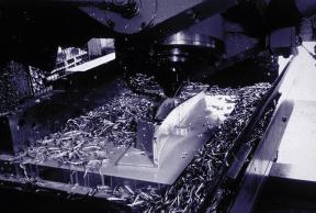
247
248 Timken Friction Management Solutions for Super Precision Applications TSMA and TSMR Tapered Roller Bearings Engineered Surfaces Precision Plus TM Extra Precision (Level 000/AA) Timken Fafnir Friction Management Solutions for Super Precision Applications Fafnir Sealed Ball Screw Support Bearings THSS (Sealed Spindle Bearings) World Class Super Precision Bearing Technology Timken Services for Super Precision Applications Bearing Repair and Remanufacturing Integrated Packages Kitting Services Friction Management Solutions Quick Change Program Timken Super Precision Bearings / 247

249 Timken Friction Management Solutions Timken can globally assist its customers to leverage their machine tool bearing investments with an array of related products and services designed to provide excellent value and impressive results. With its long, successful history of innovation and leadership, Timken works with its customers to pursue key production goals with unique antifriction solutions such as these: TSMA/TSMR Bearings Single-row tapered roller design Unique feature design used to prevent oil starvation during high speeds TSMA: axial lube lines in inner ring enable customers to employ a manifold-type lubricant reservoir for circulation to critical surfaces. TSMR: radial lube lines in inner ring allow oil movement from the equipment s shaft or housing design structure. Conceived for high speed, high stiffness requirement applications. See Timken publication Order No for more information. Engineered Surfaces Improve wear and fatigue resistance from a variety of applied surface treatments developed through years of research by Timken tribologists. Engineered surface treatments and finishes provide significant improvements to surface material or design properties. Treatment options include varying degrees of wear resistance/friction reduction and surface hardness. Surface treatments may be added to other contact surfaces (beyond bearing components). See Timken publication Order No for more information. 248 / Timken Super Precision Bearings
 precision grade.")
. See Timken publication Order No.")
250 Precision Plus Overall (total) radial runout less than a single micron (40 millionths of an inch). Ultra precision application requirements for aerospace, automotive and military markets. Timken s ultimate Level 000 (AA) precision grade. Available for sizes up to 315mm OD ( inches). Combines high stiffness features of tapered roller bearing with superior precision of ball bearing. Optimized manufacturing process created to produce finished product tolerance requirements (including heat treating phase). See Timken publication Order No for more information. Friction Management Solutions Timken Super Precision Bearings / 249


251 Timken and its Fafnir super precision line offer innovative products for the machine tool industry. Our customers benefit from Timken s leadership role in the quest for improving machining accuracy and productivity from solutions beyond Timken s traditional expertise in tapered roller bearing technology. MMN/MMF Sealed Ball Screw Support Bearings Sealed, integral double-row bearings for ball screw support locations. Options for higher speeds using ceramic ball complement and selective grease. Flanged and cartridge mount designs for more flexible installation arrangements. ABEC9/ISO P2 level axial runout tolerances promote smooth, clean machining paths. Consistent, repeatable performance provided by preloaded ring assembly. Low torque, positive-contact seals minimize drag friction. See pages or Timken publication Order No for more information. THSS (True High Speed Sealed) Spindle Bearings Maintenance free service provided by dynamic non-contact, high speed seals. Effects of elevated operating temperatures minimized with standard ceramic ball complement offering. Seal configuration significantly reduces problems arising from outside contaminants. Built upon the proven Fafnir HX design geometry. See Timken publication Order No for more information. 250 / Timken Super Precision Bearings

252 Continuous Improvements in Manufacturing Timken has invested millions of dollars into its super precision ball bearing product line to provide the highest possible level of quality in every bearing Timken ships to every customer: Using the world s most perfectly shaped, ultraclean spherical grade 5 balls. Applying superfinish process to unloaded bearing surfaces to further minimize contamination. Extensive program of ultrasonic cleaners and demagnetizers. Filtration of contaminants from all airborne and machining fluids. Continuous monitoring of temperature, humidity, and atmospheric particulate content controls. Ultimately, Timken Super Precision ball bearings operate with lower vibration levels, which generate less heat while extending service life and enhancing cutting accuracy. Friction Management Solutions Timken Super Precision Bearings / 251


253 Services Timken s wide array of friction management services help maximize machine tool productivity, including: Bearing Repair Center One-year limited warranty. Diagnostic wear pattern analysis. Servicing all sizes, styles and brands. Supplying new or remanufactured components when necessary. Extends bearing service life at only a fraction of replacement cost. See Timken publication Order No for more information. Integrated Packages Optimized bearing/housing systems specified for more demanding customer application requirements. Integrated packages of seals, housings, and lubrication selection are matched to deliver the most favorable results in product performance. Single source saves time and reduces effort searching for multiple suppliers. See Timken publication Order No for more information Bearing Kitting Assemble optimized, matched bearings and related components into a single inventory item saving lost time in supplier research and purchasing efforts. Carefully specified items eliminate wasted efforts consulting with several manufacturers for compatibility issues. Significantly reduces inventory items and purchase order generation. Highly trained and knowledgeable Timken application engineers put years of experience to work on assembling required products from multiple suppliers to meet specific customer performance goals. 252 / Timken Super Precision Bearings
. Extends flexibility of unused spindle bearings by applying customer requested enhancements.")
254 Quick Change Program Fast conversion of idle spindle bearing stock to suit immediate, specific customer shop floor requirements. Delivery times in three to five business days (24 hrs. to meet special, emergency needs). Extends flexibility of unused spindle bearings by applying customer requested enhancements. Original Timken Fafnir bearings will be covered by conditions of the initial warranty. Assortment of possible service can help alleviate production bottlenecks by providing needed machine performance from existing bearing inventory without the delay of purchasing custom bearings. - Lubrication Changes - Preload Changes - Repackaging - Recertification - Noise Testing - Bore and OD Coding - Special Marking Requirements - Reworking Competitor Bearings Friction Management Solutions Timken application engineering expertise is only a phone call away. Highly skilled technical assistance can be reached by calling (US and Canada): Outside this region, call , or visit our website at: Timken Super Precision Bearings / 253
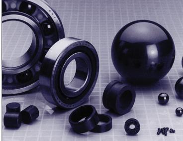
255
CLASSIFICATION OF ROLLING-ELEMENT BEARINGS
 CLASSIFICATION OF ROLLING-ELEMENT BEARINGS Ball bearings can operate at higher speed in comparison to roller bearings because they have lower friction. In particular, the balls have less viscous resistance
Chapter 11 Rolling Contact Bearings
 Chapter 11 Rolling Contact Bearings 1 2 Chapter Outline Bearing Types Bearing Life Bearing Load Life at Rated Reliability Bearing Survival: Reliability versus Life Relating Load, Life, and Reliability
TRANSLATION (OR LINEAR)
") 5) Load Bearing Mechanisms Load bearing mechanisms are the structural backbone of any linear / rotary motion system, and are a critical consideration. This section will introduce most of the more common
5) Load Bearing Mechanisms Load bearing mechanisms are the structural backbone of any linear / rotary motion system, and are a critical consideration. This section will introduce most of the more common
Friction Management Solutions for Industrial Gear Drives
 Friction Management Solutions for Industrial Gear Drives A complete range of bearings and complementary services help the gear drive industry to meet ever-increasing requirements in product reliability
Bearings. Rolling-contact Bearings
 Bearings A bearing is a mechanical element that limits relative motion to only the desired motion and at the same time it reduces the frictional resistance to the desired motion. Depending on the design
Proven to be better. Development trends in industrial rolling bearings
 Proven to be better Development trends in industrial rolling bearings Contents 1. General trends in power transmission and in machine construction and plant engineering Page 3 2. General trends in rolling
Ch# 11. Rolling Contact Bearings 28/06/1438. Rolling Contact Bearings. Bearing specialist consider matters such as
 Ch# 11 Rolling Contact Bearings The terms rolling-contact bearings, antifriction bearings, and rolling bearings are all used to describe the class of bearing in which the main load is transferred through
Kaydon white paper The thin section bearing of today
 The thin section bearing of today by Joe Zagar, engineering specialist an SKF Group brand Thin section bearings provide space, save weight The ubiquitous ball bearing was a workhorse of industry throughout
Classification and Characteristics of Rolling Bearings
 1. Classification Characteristics of Rolling Beas 1.1 Rolling bea construction Most rolling consist of s with raceway (inner outer ), rolling elements (either balls or rollers) cage. The cage separates
Why bigger isn t always better: the case for thin section bearings
 White Paper Why bigger isn t always better: the case for thin section bearings Richard Burgess, Les Miller and David VanLangevelde, Kaydon Bearings Typical applications Thin section bearings have proven
Installation Procedures
 For the precision ball and roller bearings supplied by MRC Bearings, skill and cleanliness while handling, mounting and dismounting are necessary to ensure satisfactory bearing performance. As precision
2. SELECTING THE RIGHT PART NUMBER
 A. SELECTING BY LIFE AND CAPACITY... 27 28 1. Basic dynamic load rating... 27 2. Timken dynamic load rating... 27 2.1. K factor B. SELECTING BY SIZE... 28 C. SELECTING WITH A SALES ENGINEER OR REPRESENTATIVE...
TECHNICAL INFORMATION
 General Nomenclature Spherical Roller Bearings The spherical roller bearing is a combination radial and thrust bearing designed for taking misalignment under load When loads are heavy, alignment of housings
MAIN SHAFT SUPPORT FOR WIND TURBINE WITH A FIXED AND FLOATING BEARING CONFIGURATION
 Technical Paper MAIN SHAFT SUPPORT FOR WIND TURBINE WITH A FIXED AND FLOATING BEARING CONFIGURATION Tapered Double Inner Row Bearing Vs. Spherical Roller Bearing On The Fixed Position Laurentiu Ionescu,
Six keys to achieving better precision in linear motion control applications
 profile Drive & Control Six keys to achieving better precision in linear motion control applications Achieving precise linear motion Consider these factors when specifying linear motion systems: Equipped
SKF Explorer angular contact ball bearings. Designed to run faster, cooler, smoother, longer
 SKF Explorer angular contact ball bearings Designed to run faster, cooler, smoother, longer Improve performance and increase service life Screw compressors, pumps and gearboxes require bearing arrangements
Axial-radial cylindrical roller bearings
 Axial-radial cylindrical roller bearings Designs and variants.............. 320 Bearing data..................... 321 (Boundary dimensions, tolerances) Product table 5.1 Axial-radial cylindrical roller
bearings (metric series)
") Taper roller bearings (metric series) 32302 B J2 / Q CL7C Nomenclature 1 2 3 4 1. Contact angle: 3. Features: B Larger contact angle than standard Q Improved friction torque characteristics and raceway
Taper roller bearings (metric series) 32302 B J2 / Q CL7C Nomenclature 1 2 3 4 1. Contact angle: 3. Features: B Larger contact angle than standard Q Improved friction torque characteristics and raceway
TECHNICAL INFORMATION
 Radial Roller Bearings Fitting and Mounting Fixed Bearings and Float Bearings Radial and axial loads in bearing units can be transmitted by fixed and floating bearings A fixed bearing is generally used
FUNCTION OF A BEARING
 Bearing FUNCTION OF A BEARING The main function of a rotating shaft is to transmit power from one end of the line to the other. It needs a good support to ensure stability and frictionless rotation. The
Chapter 11 Rolling Contact Bearings
 Chapter 11 Rolling Contact Bearings 1 2 Chapter Outline 3 Overview The term rolling bearing is used to describe class of bearing in which the main load is transferred through elements in rolling contact
SKF Energy Efficient deep groove ball bearings. Reduced friction for reduced energy use
 SKF Energy Efficient deep groove ball bearings Reduced friction for reduced energy use SKF Energy Efficient bearings Engineered to promote sustainability As the need to conserve energy grows more apparent
SKF Super-precision Bearing Lubrication Unit. Improved reliability, profitability and reduced environmental impact
 SKF Super-precision Bearing Lubrication Unit Improved reliability, profitability and reduced environmental impact Benefit your business and the environ To meet the ever-growing performance requirements
TIMKEN DEEP GROOVE BALL BEARINGS
 TIMKEN DEEP GROOVE BALL BEARINGS DEEP GROOVE BALL BEARING CATALOG INDEX DEEP GROOVE BALL BEARINGS Deep Groove Ball Bearing Range...1 Bearing Size Range...1 Standard 6000 Series...2 Thin-Section 61000 Series...6
Assemblies for Parallel Kinematics. Frank Dürschmied. INA reprint from Werkstatt und Betrieb Vol. No. 5, May 1999 Carl Hanser Verlag, München
 Assemblies for Parallel Kinematics Frank Dürschmied INA reprint from Werkstatt und Betrieb Vol. No. 5, May 1999 Carl Hanser Verlag, München Assemblies for Parallel Kinematics Frank Dürschmied Joints and
Wind Energy Solutions
 Wind Energy Solutions Around the world, wind turbine designers and operators are turning to Timken for power transmission and friction management solutions that increase uptime and improve total system
Advantages and Disadvantages of Rolling Contact Bearings Over Sliding Contact Bearings
 Advantages and Disadvantages of Rolling Contact Bearings Over Sliding Contact Bearings Advantages 1. Low starting and running friction except at very high speeds. 2. Ability to withstand momentary shock
Bearing preload. Preload considerations
 Bearing preload There may be some applications where the bearing arrangement needs to be preloaded i.e. requires a negative operating clearance. In applications such as machine tool spindles, automotive
BEARINGS FOR RAILWAY APPLICATIONS
 BEARINGS FOR RAILWAY APPLICATIONS BEARINGS FOR RAILWAY APPLICATIONS The railway industry is a promising field world-wide. ZKL therefore dedicates special attention to the bearings for rail vehicles. The
10 Thrust ball bearings
 10 Thrust ball bearings Designs and variants.............. 1010 Single direction thrust ball bearings... 1010 Double direction thrust ball bearings.. 1010 Cages............................ 1010 Bearings
TIMKEN SNT SPLIT PLUMMER BLOCKS
 TIMKEN SNT SPLIT PLUMMER BLOCKS TIMKEN SNT SPLIT PLUMMER BLOCKS 1 TABLE OF CONTENTS INTRODUCTION... 3 TIMKEN SNT SPLIT PLUMMER BLOCKS...4 SEAL OPTIONS AND DESCRIPTIONS...6 SEAL SELECTION AND CONFIGURATION
Modification Method of Back-up Roll Bearing by Replacing Oil Film Bearing with Rolling Bearing
 TECHNICAL REPORT Modification Method of Back-up Roll Bearing by Replacing Oil Film Bearing with Rolling Bearing J. KUBO N. SUZUKI As back-up roll s in rolling mills must support several thousand tons of
Comparison Chart. extremely difficult. Finally, separated components can rarely be re-used.
 JAN 2014 Traditional Connections Why Go Keyless Keyed Bushing Systems Both QD and Taper-Lock bushing and weld-on hub systems are popular component mounting technologies. Yet both are ultimately keyed connections
High Capacity Tapered Roller Bearings
 NTN TECHNICAL REVIEW No.73 New Product High Capacity Tapered Roller Bearings - Super Low Torque High Rigidity Tapered Roller Bearings - Takashi TSUJIMOTO Jiro MOCHIZUKI Tapered roller bearing have greater
AGN 076 Alternator Bearings
 Application Guidance Notes: Technical Information from Cummins Generator Technologies AGN 076 Alternator Bearings BEARING TYPES In the design of STAMFORD and AvK alternators, the expected types of rotor
YOUR PARTNER FOR THE MACHINING OF CRANKSHAFTS AND CAMSHAFTS. A Company of the SWAROVSKI Group
 YOUR PARTNER FOR THE MACHINING OF CRANKSHAFTS AND CAMSHAFTS A Company of the SWAROVSKI Group www.tyrolit.com TYROLIT TECHNOLOGICAL LEADER AND PARTNER ON EQUAL FOOTING TYROLIT has been developing innovative
SKF Explorer spherical roller bearings Optimized for superior field performance
 SKF Explorer spherical roller bearings Optimized for superior field performance Continuous improvement to optimize The timeline below illustrates SKF milestones in the development of self-aligning bearings.
INFLUENCE OF CROSS FORCES AND BENDING MOMENTS ON REFERENCE TORQUE SENSORS FOR TORQUE WRENCH CALIBRATION
 XIX IMEKO World Congress Fundamental and Applied Metrology September 6 11, 2009, Lisbon, Portugal INFLUENCE OF CROSS FORCES AND BENDING MOMENTS ON REFERENCE TORQUE SENSORS FOR TORQUE WRENCH CALIBRATION
Vibrating Mechanism Bearings
 Vibrating Mechanism Bearings Vibrating equipment represents some of the most demanding applications for anti-friction roller bearings. This type of equipment includes screens, vibrating finishing mills,
Bearing Fundamentals. Timken Training
 Bearing Fundamentals Timken Training AGENDA Basic Bearing Design Ball Bearings Cylindrical Roller Bearings (CRB) Spherical Roller Bearings (SRB) Tapered Roller Bearings (TRB) 2 BASIC BEARING DESIGN Anti-Friction
Specialty Ball Bearings
 Specialty Ball Bearings Providing custom-engineered bearing solutions to industry for over 100 years ISO 9001:2000 www.rbcbearings.com 800.390.3300 RBC Bearings Incorporated (RBC Bearings, RBC) has had
SKF hub units. Equipped with tapered roller bearings
 SKF hub units Equipped with tapered roller bearings A passion for innovation Solutions for the demands of today and tomorrow SKF has always been known as a leader in the development of innovative bearing
Bearings and steel balls
 Bearings and steel balls Deep groove ball bearings DIN 625 T1 P. 2-5 Deep groove ball bearings stainless steel DIN 625 T1 P. 2-15 Angular ball bearings DIN 628 T1 P. 2-17 Spindle bearings DIN 628 T1 P.
SKF fan upgrade services. One source for a full range of solutions, from unique bearing systems to circulating oil lubrication systems
 SKF fan upgrade services One source for a full range of solutions, from unique bearing systems to circulating oil lubrication systems Are productivity goals To meet ambitious new productivity goals, many
3. BEARING ARRANGEMENT DESIGN
 3. BEARING ARRANGEMENT DESIGN 3.1 GENERAL PRINCIPLES OF ROLLING BEARING ARRANGEMENT DESIGN Rotating shaft or another component arranged in rolling bearings is guided by them in radial as well as in axial
Super-low Friction Torque Technology of Tapered Roller Bearings for Reduction of Environmental Burdens
 TECHNICAL REPORT Super-low Friction Torque Technology of Tapered Roller Bearings for Reduction of Environmental Burdens H. MATSUYAMA K. KAWAGUCHI A. UEMURA N. MASUDA We developed a tapered roller bearing
CD Couplings SERIES A1C. MTY (81) MEX (55) QRO (442) DIST.
 MEX (55) QRO (442) DIST.") CD Couplings SERIES A1C ZERO-MAX CD COUPLINGS SERIES A1C For today s most demanding servo motor and motion control applications. CD Couplings Series A1C are precise, robust, and available in sizes and
CD Couplings SERIES A1C ZERO-MAX CD COUPLINGS SERIES A1C For today s most demanding servo motor and motion control applications. CD Couplings Series A1C are precise, robust, and available in sizes and
Factors Influencing the Performance of Ball and Rolling Bearings
 Factors Influencing the Performance of Ball and Rolling Bearings Course No: M02-033 Credit: 2 PDH Robert P. Tata, P.E. Continuing Education and Development, Inc. 9 Greyridge Farm Court Stony Point, NY
Tapered Roller Bearings in X-life Design
 Tapered Roller Bearings in X-life Design Contents Design and safety guidelines Page Features X-life... 2 Operating temperature... 4 Cages... 4 Suffixes... 4 Compensation of angular misalignments... 4
Instruction Manual for HSPA Take-Up Units
 Installation Instruction Manual for HSPA Take-Up Units Warning: To ensure the drive is not unexpectedly started, turn off and lockout the power source before proceeding. Failure to observe these precautions
Track Rollers/ Cam Followers
 Track Rollers/ Cam Followers Page Nomenclature...................................... 460 Introduction....................................... 462 Identification....................................... 462
Tapered Roller Bearings
 Single row tapered roller bearings Double row tapered roller bearings Four row tapered roller bearings 1. Types, design features, and characteristics Tapered roller bearings are designed so the tapered
Drawn cup needle roller bearings
 Drawn cup needle roller bearings Sealed drawn cup needle roller bearings... 78 Full complement drawn cup needle roller bearings... 79 3 Dimensions... 79 Tolerances... 79 Misalignment... 80 Cages... 80
Extremely High Load Capacity Tapered Roller Bearings
 New Product Extremely High Load Capacity Tapered Roller Bearings Takashi UENO Tomoki MATSUSHITA Standard tapered roller bearing Extreme high load capacity bearing NTN developed a tapered roller bearing
Tapered Roller Bearings. Reliable energy efficient suitable for high loads
 Tapered Roller Bearings Reliable energy efficient suitable for high loads Tapered roller bearings a premium product from FAG Tapered roller bearings are characterized by high radial and axial load carrying
HINDUSTAN BEARING TECHNOLOGIES. Manufacturer and Exporter of Ball & Roller Bearings. Company Profile. ISO Certified Company
 Manufacturer and Exporter of Ball & Roller Bearings Company Profile ISO 9001-2015 Certified Company Website : www.hbtbearings.com Our Vision Be globally recognized as high quality bearing manufacturer
Shifting gears: simplify your design with slewing ring bearings
 White Paper Shifting gears: simplify your design with slewing ring bearings Scott Hansen, VP, Manufacturing Planning, Kaydon Bearings, an SKF Group company A slewing ring bearing has rolling elements designed
Tire Uniformity Machine, LIBROTA
 Tire Uniformity Machine, LIBROTA Shinichiro IKAI *1, Yasuhiro MATSUSHITA *2 *1 Machinery Business Industrial Machinery Division Industrial Machinery Department *2 Machinery Business Industrial Machinery
Ball Rail Systems RE / The Drive & Control Company
 Ball Rail Systems RE 82 202/2002-12 The Drive & Control Company Rexroth Linear Motion Technology Ball Rail Systems Roller Rail Systems Standard Ball Rail Systems Super Ball Rail Systems Ball Rail Systems
LEAD SCREWS 101 A BASIC GUIDE TO IMPLEMENTING A LEAD SCREW ASSEMBLY FOR ANY DESIGN
 LEAD SCREWS 101 A BASIC GUIDE TO IMPLEMENTING A LEAD SCREW ASSEMBLY FOR ANY DESIGN Released by: Keith Knight Kerk Products Division Haydon Kerk Motion Solutions Lead Screws 101: A Basic Guide to Implementing
Reduce Costs Strengthen Performance. Timken Bearing Repair
 Reduce Costs Strengthen Performance Timken Bearing Repair How can bearing repair save money and time for me? Repaired bearings good as new really? How can I maximize the value of bearing repair services?
Serving Industries Worldwide. Mining. Aggregate. Crushers.
 Serving Industries Worldwide Mining. Aggregate. Crushers. If the environment is harsh, such as in mining operations, the byproducts of the process (heat and dust) only act to exaggerate the stresses. Scheerer
PRECISION BELLOWS COUPLINGS
 PRECISION BELLOWS COUPLINGS Bellows couplings are used where precise rotation, high speeds, and dynamic motion must be transmitted. They exhibit zero backlash and a high level of torsional stiffness, offering
Manufacturing Facilities
 Dunlop BTL Ltd - Ashford European Distribution Centre MPT House, Brunswick Road Cobbs Wood Industrial Estate Ashford, Kent TN23 1EL, United Kingdom Dunlop BTL Ltd - Consett UK Manufacturing Centre Unit
Bearing retention and clearances
 Bearing retention and clearances Bearing retention 9 Radial retention 9 Axial retention 91 Positioning of single bearing assemblies 91 Positioning of two bearing assemblies 92 Axial retention processes
The sphere roller Less is more!
 The sphere roller Less is more! Heinrich Hofmann Rainer Eidloth Dr. Robert Plank Gottfried Ruoff 109 8 The sphere roller Introduction Wheel supported by balls It started with the point, then along came
Cylindrical and Needle Roller Bearings for Vibratory Machinery. Reliable solutions for extreme requirements
 Cylindrical and Needle Roller Bearings for Vibratory Machinery Reliable solutions for extreme requirements Cylindrical and needle roller bearings for vibratory machinery Reliable solutions for extreme
Components for parallel kinematics
 Components for parallel kinematics Series GLK, GLK 2, GLK 3 and GLAE Parallel kinematic components consist of a number of parallel, longitudinally adjustable mechanical struts that are arranged between
AEROSPACE BEARINGS corporation
 For New Technology Network R AEROSPACE BEARINGS corporation # Warranty NTN warrants, to the original purchaser only, that the delivered product which is the subject of this sale (a) will conform to drawings
DESIGN AND SELECTION OF BEARINGS AND HOUSINGS USED IN MATERIAL HANDLING APPLICATIONS
 DESIGN AND SELECTION OF BEARINGS AND HOUSINGS USED IN MATERIAL HANDLING APPLICATIONS SPHERICAL ROLLER BEARINGS M. STEWART-LORD MANAGER - APPLICATION ENGINEERING SKF SOUTH AFRICA (PTY) LTD (SA) Spherical
High Speed, Low Weight Momentum/reaction Wheels. Larry Wilhide, Valley Forge Composite Tech, Inc. P.O. Box 344 Carlisle, PA (717)
") SSC99-XI-1 High Speed, Low Weight Momentum/reaction Wheels, Valley Forge Composite Tech, Inc. P.O. Box 344 Carlisle, PA 17013 (717) 776-3249 Louis Brothers, Valley Forge Composite Tech, Inc. P.O. Box 344
SSC99-XI-1 High Speed, Low Weight Momentum/reaction Wheels, Valley Forge Composite Tech, Inc. P.O. Box 344 Carlisle, PA 17013 (717) 776-3249 Louis Brothers, Valley Forge Composite Tech, Inc. P.O. Box 344
Trends Regarding Rolling Bearings for Steering Systems
 Trends Regarding Rolling Bearings for Steering Systems M. TANIYAMA * *Automotive Engineering Center, Automotive Bearing Engineering Department Many bearings are used in the columns, gears and pumps of
Cylindrical roller bearings for large electric motors
 Cylindrical roller bearings for large electric motors Cylindrical roller bearings are typically used in belt or gear driven medium- to largesized electric motors, where heavy radial loads prevail. These
LESSON Transmission of Power Introduction
 LESSON 3 3.0 Transmission of Power 3.0.1 Introduction Earlier in our previous course units in Agricultural and Biosystems Engineering, we introduced ourselves to the concept of support and process systems
SHAW-BOX INSTRUCTIONS AND PARTS LIST SHAW-BOX RIGID MOUNT I-BEAM AND PATENTED TRACK TROLLEYS (PUSH & HAND GEARED - 1/2 THRU 15 TON RATED LOADS)
") SHAW-BOX INSTRUCTIONS AND PARTS LIST SHAW-BOX RIGID MOUNT I-BEAM AND PATENTED TRACK TROLLEYS (PUSH & HAND GEARED - 1/2 THRU 15 TON RATED LOADS) GENERAL SHAW-BOX Rigid Mount I-Beam Trolleys are designed
SHAW-BOX INSTRUCTIONS AND PARTS LIST SHAW-BOX RIGID MOUNT I-BEAM AND PATENTED TRACK TROLLEYS (PUSH & HAND GEARED - 1/2 THRU 15 TON RATED LOADS) GENERAL SHAW-BOX Rigid Mount I-Beam Trolleys are designed
VIBRATING SCREEN APPLICATIONS EF800 ULTAGE. Spherical roller bearings. With You
 VIBRATING SCREEN APPLICATIONS EF800 ULTAGE Spherical roller bearings With You OPTIMIZE THE EFFICIENCY OF YOUR SCREENS THE FEATURES THAT MAKE THE EF800 OPTIMISED MASSIVE BRASS CAGE: PROVEN RELIABILITY The
Mounting Overlap Shield. Face Clamps. Gap. Seat Depth. Lead In Chamfer. Loose Fit.
 Mounting Introduction: Reali-Slim thin section ball bearings have a crosssection thickness that is much thinner than standard bearings of the same diameter, and are therefore more sensitive to shaft and
Technical Trend of Bearings for Automotive Drive Train
 SURVEY Technical Trend of Bearings for Automotive Drive Train M. KITAMURA Circumstances surrounding the automobile industry require improvement in fuel efficiency and reduction of CO 2 gas emission in
Instruction Manual for PTI Split Block Bearing Units For SAF, SDAF, SN, SNG, SNHF, S3000K & SD Series Housings
 Instruction Manual for PTI Split Block Bearing Units For SAF, SDAF, SN, SNG, SNHF, S3000K & SD Series Housings Installation SDAF SD & S3000 SAF Warning: To ensure that the drive is not unexpectedly started,
ENGINEERED SOLUTIONS Based on Reali-Slim Bearings A N I L L U S T R A T E D M O U N T I N G G U I D E
 ENGINEERED SOLUTIONS Based on Reali-Slim Bearings A N I L L U S T R A T E D M O U N T I N G G U I D E Reali-Slim thin-section bearings have contributed to reductions in weight and size in thousands of
Features of the LM Guide
 Features of the Functions Required for Linear Guide Surface Large permissible load Highly rigid in all directions High positioning repeatability Running accuracy can be obtained easily High accuracy can
Motion Technologies Bearing Products
 Page 1 of 12 Motion Technologies Bearing Products LARGE DIAMETER BEARINGS (conventional design) o Deep groove ball to 1900mm bore page 3 o Four point contact ball to 500mm bore page 3 o Single row angular
ASSEMBLY OF TROLLEY TO HOIST
 INSTRUCTIONS AND PARTS LIST RIGID MOUNT I-BEAM AND PATENTED TRACK TROLLEYS (PUSH & HAND GEARED - 1/2 THRU 15 TON RATED LOADS) GENERAL Yale Rigid Mount I-Beam Trolleys are designed especially for use on
Copyright Notice. Small Motor, Gearmotor and Control Handbook Copyright Bodine Electric Company. All rights reserved.
 Copyright Notice Small Motor, Gearmotor and Control Handbook Copyright 1993-2003 Bodine Electric Company. All rights reserved. Unauthorized duplication, distribution, or modification of this publication,
Design 3. Bearings(1/2) Bearings. Bearings. Provides support for rotating machine elements. Contents. Hamidreza G.Darabkhani. Course Leader: A.
 Bearings. Bearings. Provides support for rotating machine elements. Contents. Hamidreza G.Darabkhani. Course Leader: A.") Design 3 Bearings Hamidreza G.Darabkhani Course Leader: A. Starr Contents Bearings Bearings Classification Loads on Bearings Rolling elements bearings Ball bearings Roller bearings Needle bearings Linear
Design 3 Bearings Hamidreza G.Darabkhani Course Leader: A. Starr Contents Bearings Bearings Classification Loads on Bearings Rolling elements bearings Ball bearings Roller bearings Needle bearings Linear
Timken Type E Tapered Roller Bearing Housed Units
 Timken Type E Tapered Roller Bearing Housed Units Timken Premium All Purpose Industrial Grease Provides superior protection Effective in operating temperatures from -40ºF to +300ºF (-40ºC to +149ºC) It
Premium Bearings for Aggregate Equipment. Catalog A-1800-I BCAR BOWERR
 Premium Bearings for Aggregate Equipment Catalog A-1800-I R BOWERR BCAR Our comprehensive product portfolio of premium products includes: Spherical Roller Bearings Ball and Roller Bearing Mounted Units
TRANSDUCER INSTRUCTION MANUAL... TYPE SLIM CELL TRANSDUCER. INSTRUCTION NUMBER: AO of 9
 CLEVELAND-KIDDER SLIM CELL TRANSDUCER INSTRUCTION MANUAL... TYPE SLIM CELL TRANSDUCER INSTRUCTION NUMBER: AO-70165 1 of 9 1.0 GENERAL INFORMATION 1.1 RECEIVING AND UNPACKING Handle and unpack the equipment
Transmission Components
 Transmission Components Innovative designs that improve performance, durability and efficiency The Timken Company, a leading designer and manufacturer of engineered components for transmission applications,
Linear Motion Technology Handbook. The Drive & Control Company
 Linear Motion Technology Handbook The Drive & Control Company 1-2 Bosch Rexroth AG Linear Motion Technology Handbook R310EN 2017 (2006.07) Linear Motion and Assembly Technologies www.boschrexroth.com/brl
W o r l d C l a s s Q u a l i t y i n B a l l B e a r i n g M a n u f a c t u r i n g
 W o r l d C l a s s Q u a l i t y i n B a l l B e a r i n g M a n u f a c t u r i n g www.pfibearings.com Bearing Buyer s Guide Table of Contents Company Profile.. i World Class Quality ii Dimensional
PRODUCT FOCUS BEARING KNOWLEDGE TRAINING INTRODUCTION KNOW MORE SELL MORE WIN MORE ISSUE 137
 BEARING KNOWLEDGE TRAINING This training series should prove useful to all employees of Bearings International. These training modules are geared towards improving the technical knowledge of our sales
Chapter 7. Shafts and Shaft Components
 Chapter 7 Shafts and Shaft Components 2 Chapter Outline Introduction Shaft Materials Shaft Layout Shaft Design for Stress Deflection Considerations Critical Speeds for Shafts Miscellaneous Shaft Components
Lifters - Mechanical Roller
 Mechanical Roller Lifters Crane roller lifters are the standard by which all others are judged. From our first horizontal locking bar version, with patented roller shield body, to our latest Ultra Pro-
TIMKEN ENGINEERING MANUAL
 TIMKEN ENGINEERING MANUAL ENGINEERING MANUAL INDEX TIMKEN OVERVIEW......................................... 2 SHELF LIFE POLICY...6 INTRODUCTION...8 BEARING SELECTION PROCESS...9 Bearing Types...10 Cages...28
White Paper Bearing Lubrication
 White Paper Bearing Lubrication Lubrication of Rolling Bearings One of the most important requirements for effective function of bearing arrangements is proper lubrication. The lubricant forms the layer
Link-Belt Cylindrical Roller Bearings
 Link-Belt Cylindrical Roller s These bearings require minimum space and provide maximum rated capacity. Link-Belt Cylindrical Roller s Features & Benefits - 1 Link Belt Cylindrical Roller s Features and
White Paper: The Physics of Braking Systems
 White Paper: The Physics of Braking Systems The Conservation of Energy The braking system exists to convert the energy of a vehicle in motion into thermal energy, more commonly referred to as heat. From
Intelligent Balancing Solutions
 Intelligent Balancing Solutions Smooth running brought to the point. Measuring and Balancing Technologies from Hofmann In every vehicle on the road, on rails, in the air, and on water a large number of
Repeatability. Prototyping. High Precision Lead Screws
 High Repeatability High accuracy Short Lead times Fast Prototyping High Precision Lead Screws Offering smooth, precise, cost effective positioning, lead screws are the ideal solution for your application.