Fuller Heavy Duty Transmissions TRSM0503 October 2007
|
|
|
- Jonathan Foster
- 6 years ago
- Views:
Transcription
1 Service Manual Fuller Heavy Duty Transmissions TRSM0503 October 2007 RTX RTX RTXF RTXF-12515
2 Table of Contents Model Designations Description Specifications Lubrication Operation Air Systems Preventive Maintenance Changing Input Shaft Disassembly Precautions Disassembly Instructions I. Shifting Controls A. Deep Reduction Air System (RT-12515) B. Range Shift Air System C. Gear Shift Lever Housing D. Shift Bar Housing II. companion Flange, Auxiliary Housing and Clutch Housing Front Section A. Auxiliary Drive Gear B. Left Reverse Idler Gear C. Countershaft Bearings D. Mainshaft E. Drive Gear F. Countershafts G. Right Reverse Idler Gear IV. Auxiliary Section RT-1110 Series A. Range Shift Cylinder B. Auxiliary Countershafts C. Synchronizer D. Low Speed Gear and Output Shaft V. Auxiliary Section RT Series A. Range Shift Cylinder B. Auxiliary Counershafts C. Synchronizer D. Output Shaft VI. Auxiliary Section RT Series A. Range Shift Cylinder B. Auxiliary Counterhafts C. Synchronizer D. Low Range Gear and Range Mainshaft E. Deep Reduction Shift Cylinder F. Output Shaft Inspection Torque Ratings Reassembly Precautions Reassembly Instructions I. Auxiliary Section-RT-1110 Series A. Output Shaft B. Synchronizer C. Auxiliary Countershafts D. Range Shift Cylinder II. Auxiliary Section RT Series A. Output Shaft B. Synchronizer C. Auxiliary Countershafts D. Range Shift Cylinder III. Auxiliary Section RT Series A. Output Shaft B. Range Mainshaft C. Deep Reduction Shift Cylinder D. Low Range Gear E. Synchronizer F. Auxiliary Countershafts. G. Range Shift Cylinder.... IV. Front Section A. Right Reverse Idler Gear. B. Countershafts C. Countershaft Installation D. Drive Gear E. Drive Gear Installation.. F. Left Countershaft Timing Mainshaft Axial Clearances.... G. Mainshaft H. Mainshaft Installation... I. Left Reverse Idler Gear.. J. Mainshaft Final Installation K. Auxiliary Drive Gear V. Companion Flange, Auxiliary Housing and Clutch Housing VI. Shifting Controls A. Shift Bar Housing B. Gear Shift Lever Housing C. Air System Tool Reference
3 RT-lll O Roadranger RTO Roadranger 1100 Ibs.-ft, RT Roadranger RTO Roadranger 1250 Ibs.-ft. RT Roadranger RTO Roadranger 1250 Ibs.-ft. F Model Designations transmission, twin countershaft, 10 speeds, 1100 lbs./ft. torque capacity. transmission, twin countershaft, 10 speeds, including an overdrive ratio, torque capacity. transmission, twin countershaft, 10 speeds, 1250 lbs./ft. torque capacity. transmission, twin countershaft, 10 speeds, including an torque capacity. transmission, twin countershaft, 15 speeds, 1250 lbs./ft. transmission, twin countershaft, 15 speeds, including an overdrive ratio, torque capacity overdrive ratio, Included in letter before numerals, such as RTF-12510, etc. denotes forward position of the gear shift lever. NOTE Illustrated parts lists with part numbers are available upon request. Write Service Department, Eaton Corporation, Transmission Division, 222 Mosel Avenue, Kalamazoo, Michigan
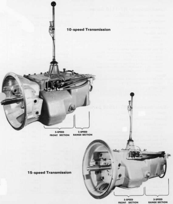
4 Description The RT-111 O and RT transmissions are designed for heavy-duty on-highway equipment. The twin countershaft design, which splits torque equally between the two shafts, provides a high torque capacity to weight ratio. Because of torque splitting, each gear set carries only half the load, greatly reducing the face width of each gear. Another unique design feature is the floating gear principle. The mainshaft gears when not engaged float between the countershaft gears, eliminating the need for gear sleeves and bushings. All gears are in constant mesh and have spur type teeth. The RT-111 O and RT transmissions have ten forward speeds and two reverse, consisting of a five-speed front section and a two-speed auxiliary or range section, both contained in one case. First through fifth speeds are obtained by using the five gear ratios in the front section through the low speed gear of the range section. Sixth through tenth speeds are obtained by using the five gear ratios in the front section through the high speed (direct drive) range gear. As in other Roadranger transmissions, the ratios are progressively spaced. The RT transmissions have 15 forward speeds and three consisting of a five-speed front section, which is identical to the RT and RT-1251O front section, and a three-speed auxiliary or range section. Both sections are contained in one case, the rear plate being extended to accommodate the extra set of gears. The 15 speeds are obtained by using the five speeds of the front section through direct drive (high range), through the low speed range gear, and through the hole-gear of the auxiliary section. The hole-gear in the RT transmissions is engaged by air when selected by the driver. 4
5 5
6 I Specifications - RT Series Speeds 10 progressive forward speeds, 2 reverse Nominal Torque Capacity 1100 lb.-ft. Input Drive Shaft 2 diameter Power Take-Off Openings Right Side: SAE standard 6 bolt regular duty type, short length. Bottom: SAE standard 8-bolt heavy-duty type. Range PTO Gear Relative Speed to Input R.P. M. Right Side: 45-tooth 6/8 pitch gear turning at.700 engine speed on RT and RTF models;.888 engine speed on RTO and RTOF models. Bottom: 47-tooth 6/8 pitch gear turning at.700 engine speed on 110 and RTF models,.888 engine Low speed on RTO and RTOF models. Range Weight SAE No. 1 aluminum clutch housing with standard controls, less clutch release parts 620 lbs. Oil Capacity Approximately 25 pints, depending on inclination of engine and transmission. Fill to level of case filler opening. GEAR RATIOS RT-111O and RTF-111O RTO and RTOF RATIO % STEP SPEED RATIO % STEP 10th th.79 9th th th th th th th th 2.16 Range Shift 30 Range Shift 29 5th th th th rd rd nd nd St St 7.65 High High Reverse 2.74 Reverse 2.16 Low Low I Reverse 9.71 Reverse 7.65 Specifications - RT-I 2510 Series Speeds 10 progressive forward speeds, 2 reverse. Nominal Torque Capacity 1250 lb.-ft. Power Take-Off Openings Right Side: SAE standard 6-bolt regular duty type, short length. Bottom: SAE standard 8-bolt heavy-duty type. PTO Gear Relative Speed to Input R.P.M. Right Side: 45-tooth 6/8 pitch gear turning at.700 engine speed on RT and RTF models,.888 engine speed on RTO and RTOF-1251O models. Bottom: 47-tooth 6/8 pitch gear turning at.700 engine speed on RT-1251O and RTF models,.888 engine speed on RTO and RTOF models. Weight SAE No. 1 clutch housing with standard controls, less clutch release parts 698 lbs. Clutch Housing Size SAE No. 1 deep only, 6-5/8, for push or pull type clutches. Oil Capacity Approximately 25 pints, depending on inclination of engine and transmission. Fill to level of case filler opening. High Range Low Range RT-1251O and RTF-1251O ;PEED RATIO % STEP 10th th th th th 2.74 Shift 29 5th th rd nd St 9.71 High Reverse 2.74 Low Reverse 9.71 GEAR RATIOS RTO and RTOF SPEED RATIO % STEP 10th.79 9th th th th 2.16 Range Shift 5th th rd nd St 7.65 High Reverse 2.16 Low Reverse
7 Specifications - RT Series Speeds RTO and RTOF forward speeds, 3 reverse. Five deep reduction ratios, Right Side: 45-tooth 6/8 pitch gear turning.888 engine speed. plus evenly spaced ratios for a selective 11 or 12 progressive Bottom: 47-tooth 6/8 pitch gear turning.888 engine speed. ratios. Clutch Housing Size SAE No. 1 deep only, 6-5/8, for push or pull type clutches. Nominal Torque Capacity 1250 lb.-ft. Power Take-Off Openings Right Side: SAE standard 6-bolt regular duty type, short length. Bottom: SAE standard 8-bolt heavy-duty type. PTO Gear Relative Speed to Input R.P. M. RT and RTF Right Side: 45-tooth 6/8 pitch gear turning.700 engine speed. Bottom: 47-tooth 6/8 pitch gear turning.700 engine speed. Weight SAE No. 1 clutch housing, with standard controls, less clutch release parts 770 lbs. Oil Capacity Approximately 28 pints, depending on inclination of engine and transmission. Fill to level of case filler opening. GEAR RATIOS RTO and RTOF GEAR RATIOS RT and RTF Deep Red. Range RANGE RATIO % STEP SPEED % STEP RATIO % STEP SPEED.79 10th th th th th th 27 4th rd nd St St High Range Low Range Deep Red. Range RANGE RATIO % STEP SPEED % STEP % STEP SPEED th th th th th th th th rd nd r d St 28 / St High Range Low Range High Reverse Low Reverse Deep Reduction Reverse High Reverse Low Reverse Deep Reduction Reverse
8 LUBRICATION Proper Lubrication... the Key to long transmission life Proper lubrication procedures are the key to a good all-around maintenance program. If the oil is not doing its job, or if the oil level is ignored, all the maintenance procedures in the world are not going to keep the transmission running or assure long transmission life. Eaton Fuller Transmissions are designed so that the internal parts operate in a bath of oil circulated by the motion of gears and shafts. Thus, ail parts will be amply lubricated if these procedures are closely followed: 1. Maintain oil level. Inspect regularly. 2. Change oil regularly. 3. Use the correct grade and type of oil. 4. Buy from a reputable dealer. I I I I I I I I Lubrication Change and Inspection Eaton Roadranger CD50 Transmission Fluid HIGHWAY USE Heavy Duty and Mid-Range First 3,000 to 5,000 miles Factory fill (4827 to 8045 Km) Inltlal drain Every 10,000 miles Check fluid level (16090 Km) Check for leaks Heavy Duty Highway Change Interval Every 250,000 miles Change transmission ( Km) fluid, Mid-Range Highway Change Interval Every 100,000 miles (160,000 Km) or every 3 years whichever occurs first First 30 hours Every 40 hours Every 500 hours Every 1,000 hours OFF-HIGHWAY USE Change transmission fluid. Factory fill Initial drain, Inspect fluid level Check for leaks Change transmission fluid where severe dirt conditions exist. Change transmission fluid (Normal off-highway use), Heavy Duty Engine Lubricant or Mineral Gear Lubricant HIGHWAY USE First 3,000 to 5,000 miles Factory fill (4827 to 8045 Km) Initial drain. Every 10,000 miles Inspect Iubricant level, (16090 Km) Check for leaks, Every 50,000 miles Change transmission (80450 Km) lubricant, OFF-HIGHWAY USE First 30 hours Change transmission lubricant on new units Every 40 hours Inspect Iubricant level Check for leaks Every 500 hours Change transmission Iubricant where severe dirt conditions exist. Every 1,000 hours Change transmission Iubricant (Normal off-highway use), Change the oil filter when fluid or lubricant is changed. Type Recommended Lubricants Grade (SAE) Fahrenheit (Celsius) Ambient Temperature Eaton Roadranger CD50 Transmission Fluid 50 All Heavy Duty Engine 011 MI L-L-2104B C or D or 50 Above 10 o F(-12 o C.) API-SF or API-CD 40 Above 10 o F(-12 o C.) (Previous API designations 30 Below 10 o F(-12 o C.) acceptable) Mineral Gear 011 with rust 90 Above 10 o F(-12 o C.) and oxidation Inhibitor 80W Below 10 o F(-12 o C.) API-GL-1 The use of mild EP gear oil or multi-purpose gear oil is not recommended, but if these gear oils are used, be sure to adhere to the following limitations: Do not use mild EP gear oil or multi-purpose gear oil when operating temperatures are above 230 F (110 o C). Many of these gear oils, particularly 85W140, break down above 230 F and coat seals, bearings and gears with deposits that may cause premature failures. If these deposits are observed (especially a coating on seal areas causing oil leakage), change to Eaton Roadranger CD50 transmission fluid, heavy duty engine oil or mineral gear oil to assure maximum component life and to maintain your warranty with Eaton. (Also see Operating Temperatures.) Additives and friction modifiers are not recommended for use in Eaton Fuller transmissions. Proper Oil Level Make sure oil is level with filler opening. Because you can reach oil with your finger does not mean oil is at proper level. One inch of oil level is about one gallon of oil. Draining Oil Drain transmission while oil is warm. To drain oil remove the drain plug at bottom of case. Clean the drain plug before re-installing. Refilling Clean case around filler plug and remove plug from side of case. Fill transmission to the level of the filler opening. If transmission has two filler openings, fill to level of both openings. The exact amount of oil will depend on the transmission inclination and model. Do not over fill this will cause oil to be forced out of the transmission. When adding oil, types and brands of oil should not be mixed because of possible in- 4 compatibility.,.....
9 LUBRICATION Operating Temperatures With Eaton Roadranger CD50 Transmission Fluid Heavy Duty Engine Oil and Mineral Oil The transmission should not be operated consistently at temperatures above 250 o F (120 o C). However, intermittent operating temperatures to 300 o F (149 o C) will not harm the transmission. Operating temperatures above 250 o F increase the lubricant s rate of oxidation and shorten its effective life. When the average operating temperature is above 250 o F, the transmission may require more frequent oil changes or external cooling. The following conditions in any combination can cause operating temperatures of over 250 o F: (1) operating consistently at slow speeds, (2) high ambient temperatures, (3) restricted air flow around transmission, (4) exhaust system too close to transmission, (5) high horsepower, overdrive operation. External oil coolers are available to reduce operating temperatures when the above conditions are encountered. Proper Lubrication Levels as Related to Transmission Installation Angles If the transmission operating angle is more than 12 degrees, improper lubrication can occur. The operating angle is the transmission mounting angle in the chassis plus the percent of upgrade (expressed in degrees). The chart below illustrates the safe percent of upgrade on which the transmission can be used with various chassis mounting angles. For example: if you have a 4 degree transmission mounting angle, then 8 degrees (or 14 percent of grade) is equal to the limit of 12 degrees. If you have a O degree mounting angle, the transmission can be operated on a 12 degree (21 percent) grade. Anytime the transmission operating angle of 12 degrees is exceeded for an extended period of time the transmission should be equipped with an oil pump or cooler kit to insure proper lubrication. Note on the chart the effect low oil levels can have on safe operating angles. Allowing the oil level to fall 1/2 below the filler plug hole reduces the degree of grade by approximately 3 degrees (5.5 percent). Proper Lubrication Levels are Essential! Transmission Oil Coolers are: Recommended With engines of 350 H.P. and above with overdrive transmissions Required With engines 399 H.P. and above with overdrive transmissions and GCW S over 90,000 lbs. With engines 399 H.P. and above and 1400 Lbs.-Ft. or greater torque With engines 450 H.P. and above With EP or Multipurpose Gear Oil Mild EP gear oil and multipurpose gear oil are not recommended when lubricant operating temperatures are above 230 F (110). In addition, transmission oil coolers are not recommended with these gear oils since the oil cooler materials may be attacked by these gear oils. The lower temperature limit and oil cooler restriction with these gear oils generally limit their success to milder applications. Transmission Mounting Angle Dotted line showing 2 Quarts Low is for reference only. Not recommended. 5


10 Operation In the following instructions, it is assumed that the driver is familiar with motor trucks and tractors, and that he can coordinate the necessary movements of the shift lever and clutch pedal to make progressive and selective gear engagements in either direction, up or down. RT-I 110 and RT Operation The RT and RT have ten selective ratios, evenly and progressively spaced. Do not shift these transmissions as you would a conventional model with an auxiliary or two-speed axle, because there is no split-shifting. All shifts are made with one lever. The range control button is used one time only during an upshift sequence, and one time only during a downshift sequence. Since the transmissions consist of a five-speed front section and a two-speed range section, the ten forward speeds are obtained by using a five-speed shifting pattern twice the first time with the transmission in low range, and the second time with the transmission in high range. Ten speeds obtained with one gear shift lever and range control button. Shift pattern for the RT-1110 and R T-1251 O model transmissions. Shift pattern for the R TO-1I10andRTO model transmissions. 10


 If the button was down when the truck was last used, the transmission is already in low range. Downshifting 1.")


11 Upshifting To get to high range pull button UP while in 5th speed, then move lever to 6th speed. Downshifting To get to low range push button DOWN 10 6th speed, 9 8 then move 7 6 lever to 5th speed. speed. RANGE Upshifting 1. Move the gearshift lever to the neutral position. 2. Start the engine. 3. Wait for air system to reach normal line pressure. 4. Now look at the Range Control Button. If it is up push it to the down position. (With the downward movement of the button, the transmission will shift into low range.) If the button was down when the truck was last used, the transmission is already in low range. Downshifting 1. When shifting down, move the lever from 10th through each successive lower speed to 6th. 2. When in 6th, and ready for the next downward shift, PUSH the Range Control Button DOWN and move the lever to 5th speed. As the lever passes through the neutral position, the transmission will automatically shift from high range to low range. 3. With the transmission in low range, shift downward through each of the four remaining steps. 5. Now start the vehicle and shift progressively through 1st, 2nd, 3rd and 4th to 5th. 6. When in 5th and ready for the next upward shift, PULL the Range Control Button UP and move the lever to 6th speed. As the lever passes through the neutral position, the transmission will automatically shift from low range to high range. 7. With the transmission in high range, you may now shift progressively through 7th, 8th and 9th to 10th. Driving tip: always start vehicle moving in first speed gear. 11

12 General Instructions The shift through neutral is important only on the first shift made after the control button is moved. Subsequent shifts through neutral will not activate the automatic range shift until the control button is moved once more. When necessary to slow or,. stop the vehicle, shift down through the individual short steps, allowing the compression of the engine to slow the vehicle. The life of chassis and trailer brakes can thus be prolonged. When slowing the vehicle, it is also permissible to coast in high range with the clutch disengaged. The shift to low range, however, should not be made until it is necessary to accelerate the vehicle once more. Shifts will be fast and short as the gear shift lever stroke is 2% inches between positions. Conical engagement teeth are standard on these transmissions, thus helping to eliminate gear clashing. Gear ratios average 26 per cent between ratio steps. Precautions To protect the transmission from abuse, the following precautions should be observed when shifting the vehicle: Do not attempt to shift from high range to low range at high vehicle speeds. This downward range shift should be made only at a road speed equal to that provided by fifth or a lower gear at governed engine speed. Do not attempt to make any range shifts either up or down when the vehicle is moving in reverse. Stay in the range originally selected. A mylar shift diagram is furnished with each transmission should be installed on the vehicle dashboard. If it has been misplaced, new m shift diagrams can be purchased from the Service t, Transmission Division, Eaton Corporation, Kalamazoo, Michigan. Skip Shifting After becoming proficient in shifting this transmission, the operator may wish to skip some of the gear ratios to offset a particular Operating condition. Skip shifting can be done when upshifting providing the range control button is pulled up to the high range position before making any shift which passes fifth speed. Skip shifting is also possible during downshifting providing the range control button is pushed down to the low range position before making any shift which passes sixth speed. 12
13 RT and RTO Operation The RT transmission, like the RT , has a fivespeed front section and a two-speed auxiliary or range section which enables the driver to select 10 forward speeds, evenly and progressively spaced. However, the RT models have an additional five speeds obtained through a deep reduction gear (hole-gear). The 10 ratios in high and low range are obtained with one lever and a range control button. The five speeds in deep reduction are obtained with the same gearshift lever and a Deep Reduction Valve which controls the IN or OUT position of the reduction gear. The five ratios in deep reduction are evenly and progressively spaced. These five ratios, however, overlap the low range ratios and are not progressively spaced in relation to the low range ratios. The deep reduction gear should be used only when operating under adverse conditions and only when the transmission is in LOW RANGE with the control valve button down. Never move the Deep Reduction Valve to IN when in high range. When the valve is moved to IN the reduction ratios will be engaged regardless of the position of the Range Control Button. The RTO is operated in the same manner as the RT except for the reversal of the 4th and 5th gearshift lever positions. Upshift Through Low and High Range Shift upward through the 10 speeds of low and high range in the same manner as upshifting the RT or RTO model transmissions. MAKE SURE THE DEEP RE- DUCTION VALVE IS IN THE OUT POSITION AT ALL TIMES during the low and high range shifts. SHIFTING DIAGRAM OF THE RT Fifteen speeds obtained with one gear lever, a Range Control Button and a Deep Reduction Valve. (Ratios shown with each gear shift lever position.) SHIFTING DIAGRAM OF THE RTO Fifteen speeds obtained with one gear shift lever, a Range Control Button and a Deep Reduction Valve. (Ratios shown with each gear shift lever position.) One through 10 speeds... with Range Control Button... and Deep Reduction gear disengaged. One through 10 speeds... with Range Control Button... and Deep Reduction gear disengaged. Five additional ratios... with Deep Reduction gear engaged. Five additional ratios engaged.... with Deep Reduction gear 13
14 SUGGESTED SHIFT PATTERN FOR THE RT THROUGH REDUCTION AND LOW AND HIGH RANGE (Ratios shown next to each gear shift lever position) Shift 1 through 5 with range control button down and deep reduction valve to IN Move deep reduction valve to OUT while in 5th reduction... and shift through 4th & 5th of low range Pull range control button up while in 5th of low range... and shift 6th through 10th Upshift Through Deep Reduction, Low and High Range There are several patterns of upshifting depending upon 2. conditions of road and load. Check gear ratios to determine the best ratio split for your particular condition. The following instructions are recommended for average condi- 3. tions: 1. With the gearshift lever in neutral, the engine started and 4. air system pressure normal, PUSH THE RANGE CON- TROL BUTTON TO THE DOWN POSITION. Move the Deep Reduction Valve to the IN position to engage the deep reduction gear. Start the vehicle and shift progressively from 1st through 5th of the shift pattern. When in 5th speed position and ready for the next upshift, move the Deep Reduction Valve to the OUT position and shift to the 4th speed position, thus shifting 14

15 out of the reduction ratios to low range ratios. Torque will keep the reduction gear engaged until the shift out of fifth position is made. Remember, although the shift lever is moved from 5th to 4th, this is an upshift and accelerator must be moved accordingly. There will be no automatic range shift as the transmission already is in low range. 5. Shift through the 4th and 5th speed positions of low range. 6. When ready for the next upshift, pull the Range Control Button up while in the 5th speed position of low range and shift the lever to the first speed position of the shift pattern. As the lever passes through neutral, the transmission will automatically shift from low to high range. 7. Shift progressively upward from 6th through 10th in high range. Important Procedures 1. When making the shift from a reduction ratio to a low range ratio, move the Deep Reduction Valve from IN to OUT IMMEDIATELY BEFORE making the shift. This is not a pre-select valve and only torque will hold the reduction gear after the lever is moved to OUT ; the shift cylinder will make the shift by air as soon as torque is released. 2. Never move the Deep Reduction Valve lever with the transmission in high range (range control button up) as the reduction gear bypasses both the low and high range sections, regardless of the position of the range control button. 3. When downshifting it should not be necessary to shift into deep reduction ratios. The reduction in low range should be sufficient in most operating conditions. NOTE: The above is for the RT RTO shift from reduction to low range would differ, according to the ratios desired. All instructions pertaining to the Range Control Button, skip shifting and general precautions of the ten-speed shift pattern of the RT and RT-1251O apply as well to the RT
16 Air Systems Range Shift Air System All Models This system consists of an air filter, regulator, air valve, control valve, shift cylinder, fittings and connecting lines. See Illustration A. Constant regulated air is supplied to the bottom port of the air valve and to the IN port of the control valve. With the control button down, air passes through the control valve and to the end port of the air valve. This permits air from the constant supply to flow through the low range port in bottom, side cap of air valve and to the shift cylinder air port. Air on this port moves the shift piston and bar to the rear to engage the low range gear. With the control button up the control valve is closed and air is removed from end port of air valve. This permits air from the constant supply to flow through the high range port in rear, side cap of air valve and to the shift cylinder cover air port. Air on this port moves the shift piston and bar forward to engage the high range gear. When the control button is moved from one position to another, air from the previously charged line exhausts through the breather in air valve. On some transmissions the air valve may be installed in a 180 position from that shown in Illustration A. The porting on these models, however, remains the same. The bottom port in the side cap is always the low range port. 16
17 Hole-Gear Air System RT Series This system uses the air filter and regulator of the range shift air system, plus a Deep Reduction Valve, mounted in the vehicle s cab, and a hole- gearshift cylinder. See Illustration B. Constant regulated air is supplied to the end port of the deep reduction valve and to the air port in the lower, right side of the hole -gearshift cylinder cover. The deep reduction valve lever has two positions, IN and OUT. With the lever moved to the IN position the valve is off. Thus, constant air channeled through the shift cylinder and cover to the front of the shift piston moves the piston and shift bar to the rear to engage the hole-gear. As the hole-gear is engaged the range mainshaft is disengaged from the output shaft, removing the low and high range sections from the power flow. With the deep reduction valve lever moved to the OUT position air flows out the side port of the valve and to the air port near the center of the hole -gearshift cylinder cover. This air, pushing against a larger piston area than the constant air supply, moves the shift piston and bar forward to disengage the hole-gear. As the hole-gear is disengaged, the range mainshaft is engaged to the output shaft, permitting use of the low and high range sections. B. Hook-up diagram and troubleshooting checkpoints for the hole-gear air system. 17
18 Air Valve Operation With the range control button up the control valve shuts off the air supply to the end cap. Thus, the constant air ing at the constant supply port forces the piston to the rear. The constant air also flows through a channel in the center of the piston and to an external port which is aligned with the high range port of the air valve. With the control button down the control valve opens and supplies air to the end cap. Since the piston area is larger on this end of the piston, it is forced in the opposite direction. The external air port in the piston is now aligned with the low range port of the air valve. C. Exploded view of value. The alignment sleeve not part of assembly, but must be housing for proper operation. The four O-rings are indicated by circled numbers. If any of these are defective, there will be a constant air leak out of the exhaust on the air valve. In normal operation, exhaust will occur only for an instant as the range shift is made. The following chart is to be used as a guide to determine defective O-rings. Defective O-Rings RESULT 1 Constant leak through exhaust in low range only. 2or3 Constant leak through exhaust in both ranges. 4 Constant leak through exhaust in high range; steady but low volume leak through exhaust in low range. To Disassemble Air Valve 1. Turn out the two capscrews and remove the side cap 4. from valve body. 2. Remove the two O-rings from piston. 3. Remove the valve insert from piston and remove O ring 5. from the valve insert. 6. Remove the spring from piston. Turn end cap from valve body and withdraw piston from bore. Remove the nylon plug from piston and remove O-ring from plug. 18

19 Air Valve Pre-Selection An actuating pin protruding from the shifting bar housing prevents the actuating piston in the air valve from moving while the gearshift lever is in a gear position and releases the piston when the lever is moved to or through neutral. See detailed installation of air valve for installation precaution concerning the actuating pin. SLEEVE D, Cross-section actuating pin and plunger assembly. Air Regulator The air regulator is not serviceable. If defective replace the air regulator unit. Reading at output of air regulator should be 57.5 to 62.5 psi. Air Filter & Regulator Assembly 19
20 E. Exploded of control value. The IN port constant air to cap of air ualoe. supply. The OUTLET port connected by O. L). If the O-rings or parts in the control valve are defective there will be a constant air leak out the exhaust located on bottom of control valve. A defective insert valve O-ring will result in a constant leak through exhaust in both ranges and valve will not make range shifts. A defective housing O-ring will result in a constant, low volume leak through exhaust in low range only. If the slide is assembled backwards, there will be a constant leak through exhaust in high range. When installing slide in control valve make sure that slot in slide faces the outlet part. To Disassemble the Control Valve 1. Remove the four screws to separate front and rear housings Remove the slide and the two position balls and springs. Remove the flat metal seal from outlet side and remove the O-ring from body. Remove the valve insert from front housing and remove the O-ring from valve insert. Remove the wave washer installed under valve insert. Remove the two felt wipers from valve housings. Punch out roll pin and remove control button from slide. Air Valve O-Ring sizes, Ill. C Qty. Location ID Width 2 Valve Insert and Plug Piston Piston Control Valve O-Ring sizes, Ill. E 1 Valve Insert Housing
21 Trouble Shooting Range Shift Air System All Models The following checks are to be made with normal vehicle air pressure but with the engine off. Refer to Illustration A for check points Incorrect Hook-Up With normal vehicle air pressure and gearshift lever in the neutral position, move the control button up and down, from one range to another. a. If lines are crossed between the control valve and the air valve on transmission, there will be a steady flow of air from the top exhaust in control valve if button is held in the up position. b If lines are crossed between the air valve on transmission and the air or shift cylinder, the transmission gearing will not correspond with the button position. Low range, down position of button, will result in high range gear engagement in the transmission and vice versa. Air Leaks With normal vehicle air pressure and gearshift lever in the neutral position, coat all air lines and fittings with soapy water and check for leaks, moving control button to both positions. a. If there is a steady leak out exhaust of control valve, there are defective parts or O-rings in the control valve. b. If there is a steady leak out breather on air valve; there is a defective O-ring in the air valve; or there is a leak past O-rings on the shift cylinder piston (see Ill. F, Check Point E). c. If transmission fails to shift into low range or is slow to make the shift and the transmission case is pressurized, see Ill. F, Check Point E. d. Tighten all loose connections and replace defective parts or O-rings. Air Regulator, Check Point A With normal line pressure and gearshift lever in neutral, check exhaust port on side of air regulator. There should be no leak from this port If there is a steady leak from exhaust port, this indicates a defective air regulator and should be replaced. Cut off the vehicle air pressure and install air gauge in line at output port of air regulator. Bring vehicle air pressure to normal. Regulated pressure should be 57.5 to 62.5 psi. If correct pressure readings are not obtained, replace regulator. Control Valve, Check Point B With the gearshift lever in neutral, pull the control button up to high range and disconnect the 1/8" black nylon air line at air valve. a, When control button is pushed down a steady blast of air should flow from the disconnected line. Air will shut off when button is pulled up. This indicates that control valve is operating correctly. Reconnect air line. If control valve does not operate correctly, check for leaks, restrictions and defective O-rings. High Range, Check Point C With the gearshift lever in neutral, push the control button down and disconnect the high range air line from the shift cylinder cover. a. Pull the control button up. There should be a steady flow of air from the high range air line. Push button down to shut off air. b. Make sure vehicle engine is off and move the gearshift lever to a gear position. Pull the button up; there should be no air at high range line. Move the gearshift lever to neutral; there should now be a steady flow of air from the high range line. Push button down to shut off air and reconnect line. c. If air system operated incorrectly, this indicates that air valve is defective or that actuating parts in shifting bar housing are jammed or defective. 21
22 6. Low Range, Check Point D With the gearshift lever in neutral, pull the control button up and disconnect the low range air line at shift cylinder. a. Repeat procedure under Check Point C, reversing the position of the control button in order to check the low range operation. 7. Range Shift Cylinder Check Point E If any of the seals in the range shift cylinder are defective the range shift will be affected. The degree of lost air, of course, will govern the degree of failure, from slow shift to complete failure to shift. Refer to Illustration F for location of seals. Make sure cylinder bore is clean to prevent damage to piston seal. Use only a very light amount of shellac or Permatex on cover gasket to prevent clogging cylinder. Tighten cover capscrews securely. 22


23 Hole-Gear Air System RT and RTO Transmissions The following checks are to be made with normal vehicle air pressure but with the engine off. It is assumed air lines have been checked for leaks and the air regulator has been checked and the correct reading obtained. Refer to Illustrat on B for check points. 1. Air Input Check Point F With gearshift lever in neutral and normal vehicle air pressure, loosen the connection at input (end port) of the deep reduction valve until it can be determined that there is a constant flow of air at this point. Reconnect line. If there is no air at this point, there is a restriction in the line between the deep reduction valve and air valve. Also check to make sure this line is connected to constant supply. Refer to Illustration G, for location of seals Leak at seal A.... Failure to engage hole-gear; pressurizing of transmission; hole-gear can be disengaged. Leak at seal B... Failure to engage hole-gear; leak from deep reduction valve exhaust port when valve is IN. G. Cutaway. Deep Reduction Shift Cylinder. (R T models) Deep Reduction Valve Check Point G With the deep reduction valve lever to IN, remove the line from the deep reduction valve at the port in holegearshift cylinder; there should be no air at this point. Move the deep reduction valve lever to OUT. There should now be a constant air flow from line. Move lever to IN to shut off air. If the above conditions do not exist, deep reduction valve is faulty or there is a restriction in air line. Hole-Gearshift Cylinder Check Point H If any of the seals in the hole-gearshift cylinder are defective the hole-gearshift will be affected. The degree of lost air, of course, will govern the degree of failure, from slow shift to complete failure to shift. 23
24 Preventive Maintenance Check Chart CHECKS WITHOUT PARTIAL DISASSEMBLY OF CHASSIS OR CAB Air System and Connections a. Check for leaks, worn air lines, loose connections and capscrews. See Air Systems. Clutch Housing Mounting a. Check all capscrews in bolt circle of clutch housing for looseness. Tighten to recommended torque. Clutch Release Bearing a. Remove hand hole cover and check radial and axial clearance in release bearing. b. Check relative position of thrust surface of release bearing with thrust sleeve on push type clutches. Clutch Pedal Shaft and Bores a. Pry upward on shafts to check wear. b. If excessive movement is found, remove clutch release mechanism and check bushings in bores and wear on shafts. Gear Lubricant a. Change at specified service intervals. b. Use only gear oils as recommended. See Lubrication section. Filler and Drain Plugs a. Remove filler plug and check level of lubricant at specified intervals. Tighten filler and drain plugs securely. 8. Gearshift Lever Housing Assembly a. Remove air lines at air valve and remove the gearshift lever housing assembly from transmission. b. Check tension spring and washer for set and wear. c. Check the gearshift lever pivot pin and pivot pin slot for wear. d. Check bottom end of gearshift lever for wear and check slot of yokes and blocks in shift bar housing for wear at contact points with shift lever. CHECKS WITH DRIVE LINE DROPPED 9. Universal Joint Companion Flange Nut a. Check for tightness. Tighten to recommended torque. CHECKS WITH UNIVERSAL JOINT COMPANION FLANGE REMOVED 10. Splines on Output Shaft a. Check for wear from movement and chucking action of the universal joint companion flange. 11. Mainshaft Rear Bearing Cover a. Check oil seal for wear. 12. Output Shaft a. Pry upward against output shaft to check radial clear ante in mainshaft rear bearing. 7. Gear Shift Lever a. Check for looseness and free play in housing. If lever is loose in housing, proceed with Check No
25 25
26 Special Procedure For Clutch (Input) Shaft In some cases in field repair it may benecessary to replace only the input shaft due to clutch wear on the splines. In these instances the input shaft can be removed without disassembling the transmission other than removing the shifting bar housing. Removal of the clutch housing is optional. Following is the detailed procedure: Disassembly 1. Remove gearshift lever housing and shift bar housing from transmission Remove the front bearing cover. Engage the mainshaft sliding clutches in two gears and remove the drive gear bearing nut. Move the drive gear assembly as far forward as possible and remove the drive gear bearing. Remove the washer from input shaft. From the front, remove the snap ring from ID of drive gear. Pull the input shaft forward and from splines of drive gear Install snap ring in ID of drive gear. Install washer on shaft. Move the fourth-fifth speed sliding clutch gear forward to contact end of input shaft hub of drive gear. Block between rear of sliding clutch and front of the fourth speed gear. When installing bearing this will hold input shaft in position to seat the bearing properly. Install drive gear bearing on shaft and into case bore, making sure blocking remains in place. Remove blocking from mainshaft and install the drive gear bearing nut, left-hand thread. Use Loctite sealant on threads of nut and shaft. Peen nut into milled slots in shaft. Re-install front bearing cover, shifting bar housing and gearshift lever housing. NOTE: 7%e above instructions are for changing the input shaft only. To change the drive gear, complete disassembly of the fron t section must be made. Reassembly 1. Install new input shaft into splines of drive gear just far enough to expose snap ring groove in ID of drive gear. Make sure that the bushing is installed in the pocket the input shaft. 26
27 General Precautions for Disassembly IMPORTANT: Read this section before starting the detailed disassembly procedures. [t is assumed in the detailed disassembly instructions that the lubricant has been drained from the transmission, the necessary linkage and air lines removed and the transmission has been removed from the chassis. Removal of the gearshift lever housing assembly is included in the detailed instructions; however, this assembly must also be removed from transmission before removing unit from vehicle. On RT and RTO-I2515 models, air lines from the hole-gear switch in cab must be disconnected at the transmission before removing unit from vehicle. Follow each procedure closely in each section, making use of both the text and pictures. 1. BEARINGS Carefully wash and relubricate all bearings as removed and protectively wrap until ready for use. Remove all bearings with pullers designed for this purpose -- do not remove bearings with hammer and punch. 2. SNAP RINGS Remove snap rings with pliers designed for this purpose. Rings removed in this manner can be reused. 3. INPUT SHAFT The clutch or input shaft can be removed on most models without removing the countershaft, mainshaft or drive gear. See page CLEANLINESS Provide a clean place to work. It is important that no dirt or foreign material enters the unit during repairs. The outside of the unit should be carefully cleaned before starting the disassembly. Dirt is abrasive and can damage highly polished parts such as bearings, sleeves and bushings. 5. WHEN DRIVING Apply force to shafts, housings, etc., with restraint. Movement of some parts is restricted. Do not apply force after the part being driven stops solidly. Use soft hammers and bars for all disassembly work. 27

28 1. Shifting Controls. 28


29 A. Removal of the Deep Reduction Shift Air System D RT Series 1. Remove the 1/4" ID air line between the deep reduction shift cylinder and the tee fitting forward of the filter / regulator assembly. B. Removal of the Range Shift Air System 1. Disconnect the black and white 1/8" OD air line at the air valve on the side of the transmission. NOTE: The gear shift lever housing, range control valve and lines may now be removed as a unit by turning out the four capscrews at the base of the gear shift lever housing. 2. Disconnect the black and white 1/8" O D air line at the range control valve on the shift lever. 29


30 Disassembly - Air System B. Removal of the Range Shift Air System - continued 5. Remove the hose clamp and disconnect the two 1/4" ID air lines between air valve and the range shift cylinder. Loosen the clamp holding the range control valve to the lever. 6. Disconnect the 1/4" ID air line between the air valve and the filter/regulator assembly. Turn the shift ball from the top of the lever and remove the valve, air lines, sheathing and o-rings. For further disassembly of the range control valve, refer to page 20. NOTE: For ease of reassembly, it is advisable to tag the 1/4" I.D. air lines as to their proper locations during removal. 7. Remove the filter/regulator assembly from the auxiliary housing. For further disassembly, refer to page


31 8. Turn out the four capscrews and remove the air valve from the side of the front case. For further disassembly of the air valve, refer to page Remove the spring and plunger from the bore in the adaptor plate. Remove the alignment sleeve bore in the adaptor plate. from the air valve or the 11. Turn out the two capscrews and two Allen head screws and remove the adaptor plate from the side of the case. 31


32 c. Removal and Disassembly of the Gear Shift Lever Housing 1. Turn out the four capscrews, jar lightly to break the gasket seal and lift the gear shift lever assembly from the shift bar housing. 4. Turn out the nut and remove the pivot pin from the housing. 2. Remove the rubber dust cover from the lever and mount the assembly in a vise by the housing. Free the tension spring from the housing by inserting a large, heavybladed scredriver between the spring and the housing and twisting. Force the spring from under the lugs in the housing one coil at a time. 5. Remove the O-ring from the groove in the top of the housing. 3. Remove the tension spring washer and lever from the housing. 32


33 D. Removal and Disassembly of the Shift Bar Housing Assembly 1 Turn out the retaining capscrews, jar to break the gasket seal and lift the shift bar housing from the case. 3. Mount the housing on its side in a vise with the exposed end of the actuating plunger facing up. NOTE: Lay all parts on a clean bench in the order of removal to facilitate reassembly. Bars not being removed must be kept in the neutral position or interlock parts will lock the bars, preventing removal. 2. Remove the three tension springs and tip the housing to remove the three tension balls located under the springs. If necessary, remove the reverse light pin and plug from the housing. 4. Cut the lockwire, turn out the lockscrews and remove the oil trough from the side of the shift bar housing. (Oil trough is optional ) 33
34 D. Disassembly of the Shift Bar Housing - continued 5. Cut the lockwires, turn out the lockscrews and remove the 4th-5th speed shift bar, block and yoke from the housing. 7. CRemove the actuating plunger from the bore in the housing. 6. Cut the lockwires, turn out the lockscrews and remove the 2nd-3rd speed shift bar, block and yoke from the housing. As the neutral notch clears the housing boss, remove the interlock pin from the notch. 8. Cut the lockwire, turn out the lockscrew and remove the lst-reverse speed shift bar and yoke. 34
35 Shift Bar Housing 9. Remove the two interlock balls from the bore in the housing boss. 35


36 Companion Flange, auxiliary housing and Clutch Housing II. Companion Flange, Auxiliary Housing and Clutch Housing A. Removal of the Companion Flange or Yoke 1. Use a large breaker bar to remove the stop nut from the output shaft. 2. Remove the stop nut washer and companion flange or yoke from the splines of the output shaft. B. Removal of the Auxiliary Housing NOTE: The RT auxiliary housing is shown in the following steps, but the procedure is the same for the RT and RT-1110 series transmissions. 1. Turn out the capscrews and insert three puller screws in the three tapped holes in the auxiliary housing flange. Tighten the puller screws evenly to move the housing approximately 1/2" to the rear. 2. Attach a chain hoist to the auxiliary housing and move the housing to the rear and off the front case dowel pins. 36


37 Companion Flange, auxiliary housing and Clutch Housing 3. The transmission can also beset vertically to remove the auxiliary housing. Block under the clutch housing to prevent damage to the input shaft and lift the auxiliary housing upwards and from the front case. c. Removal of the Clutch Housing 1. If so equipped, remove the clutch release mechanism and/or upshift clutch brake and turn out nuts and bolts securing the clutch housing to the front case. 2. Jar the clutch housing with a rubber mallet to break the gasket seal and pull the housing straight forward and off the studs and front bearing cover. 37


38 III Front Section A. Removal and Disassembly of the Auxiliary Drive Gear Assembly 1. Remove the mainshaft rear snap ring from the shaft. 3. Insert three puller screws in the tapped holes of the retainer ring and tighten evenly to remove the drive gear assembly from the case bore. 2. Cut the lockwires and remove the lockscrews from the bearing retainer ring. 4. Remove the snap ring from the hub of the auxiliary drive gear and press the retainer ring and bearing from the gear. 38


39 Front Section B. Removal and Disassembly of the Left Reverse Idler Gear Assembly 1. Move the mainshaft possible and remove gear. reverse gear as far to the rear as the snap - ring from the ID of the 3. Use inside jaw pullers to remove the left auxiliary countershaft front bearing from the reverse idler bore. The right auxiliary countershaft front bearing may also be removed at this time. 2. Move the reverse gear forward and against theist speed gear, engaging the splines of the sliding clutch. 4. Remove the elastic stop nut and washer from the front of the idler shaft. 39


40 B. Disassembly of the Left Reverse Idler Gear Assembly - continued 5. Remove the plug from the bore in the rear of the idler shaft, insert an impact puller in the bore and remove the shaft. 7. If necessary, remove the bearing inner race and rear washer from the idler shaft. 6. As the shaft is moved to the rear, remove the gear and thrust washer from the case. 40


41 C. Removal of the Countershaft Bearings 1. Remove the snap ring from the rear of each countershaft. 4. Use a soft bar and mall to drive each countershaft as far to the rear as possible. This will partially unseat the front bearings. 2. From inside the case, use a mall and punch to drive the countershaft rear bearings to the rear and from the case bores and shafts. NOTE: Removal procedures will most likely damage the bearings and removal should not be attempted unless replacement of the bearings is planned. 5. Use a soft bar and mall on the rear of each countershaft to drive each shaft as far forward as possible, unseating the front bearings from the case bores. This will expose the front bearing snap rings. 3. Cut the lockwires, turn out the lockscrews and remove the two front bearing retaining plates. 6. Use a bearing puller to remove the countershaft front bearings. 41


42 D. Removal and Disassembly of the Mainshaft Assembly 1. Block the right countershaft against the side of the case and move the mainshaft as far to the rear as possible. Tip the front of the mainshaft up and remove the assembly from the case. Use caution as the reverse gear is free and may fall from the shaft. 4. Remove the reverse gear spacer and pull the key to the rear and from the mainshaft. NOTE: When removing washers, spacers and gears, note their location to facilitate reassembly of the mainshaft. Keep washers and spacers with the gear from which they were removed; there is one spacer and one washer for each gear. The spacers have external splines and the washers have internal splines. 2. Remove the 4th-5th speed sliding clutch. 5. Work the washers, spacers and gears from the mainshaft. It will be necessary to turn the washers, located in the hubs of the gears, to align with the splines of the mainshaft. If necessary, remove the snap ring from the hub of each gear. 3. Remove the snap ring from the rear of the mainshaft. 42


43 E. Removal and Disassembly of the Drive Gear Assembly 1. Turn out the f rent bearing cover retaining capscrews and from inside the case, use a soft bar and mall to move the drive gear forward. This will force the front bearing cover away from the case. Remove the front bearing cover from the input shaft. 3. Move the drive gear assembly to the rear and into the case, working past the countershaft gears. Remove the drive gear assembly from the case. 2. Remove the snap ring from the drive gear bearing. 4. Relieve the drive gear bearing nut at the points where it is peened into the milled slots of the shaft. 43
 6.")

44 E. Disassembly of the Drive Gear Assembly - continued 5. Turn the bearing nut from the shaft. (LH thread) 6. Using the rear face of the drive gear as abase, press the shaft through the gear to unseat the bearing from the shaft. This will free the bearing, spacer and drive gear. If necessary, remove the snap ring from the drive gear. 44


45 F. Removal and Disassembly of the Countershaft Assemblies NOTE: Except for the number of teeth on the PTO gear, the countershaft assemblies are identical and are disassembled in the same manner. IMPORTANT: Never use the PTO gear as a pressing base. The narrow thickness of this gear makes it susceptible to breakage. 1. Move the right countershaft to the rear as far as possible, moving the front of the shaft to the inside of the case. Lift the shaft from the case and repeat the procedure for the left countershaft. 3. Using the 2nd speed gear as a base, press the 2nd and 3rd speed gears from the shaft. If necessary, use a hammer and punch to remove the key from the countershaft keyway. 2. Remove the spacer from the front of the countershaft and using the 4th speed gear as a base, press the direct, PTO and 4th speed gears from the shaft. This will require a press of at least 25 ton capacity. Use a safety shield as a precaution. G. Removal and Disassembly of the Right Reverse Idler Gear Assembly NOTE: The right reverse idler gear assembly is identical to the left and is disassembled in the same manner. 45


46 IV. Auxiliary Section - RT-1110 Series A. Removal and Disassembly of the Range Shift Cylinder Assembly 1. For ease of disassemble y, mount the auxiliary section upright in a vise. Turn out the capscrews and remove the range shift cylinder cover. 4. Pull the yoke bar to the rear and out of the cylinder. Remove the piston from the housing. 2. Turn the nut from the end of the shift yoke bar. 5. Remove the O-rings from the OD and ID of the piston. 3. Cut the lockwire and turn out the two yoke lockscrews. 6. Turn out the capscrews and remove the shift cylinder housing from the auxiliary plate. Remove the shift yoke from the sliding clutch gear of the synchronizer assembly. If necessary, remove the O-ring from the bore in the cylinder housing. 46


47 6. Removal of the Auxiliary Countershaft Assemblies 3. Use a soft bar and mall to drive the countershaft forward and from the rear bearings. 1. Turn out the capscrews and remove the two rear bearing covers. 4. Remove the bearings from the bores by tapping lightly and evenly to the rear with a soft bar. 2. Remove the snap ring from the rear of each countershaft. NOTE: Check the bearing inner race on the front of each countershaft t. If worn or damaged, remove with pry bars or appropriate jaw pullers. If the auxiliary countershaft t f rent bearings are to be changed, these inner races must be changed also. c. Removal and Disassembly of the Synchronizer Assembly 1. Pull the synchronizer assembly from the splines of the output shaft. 2., Pull the direct (high range) cone synchronizer from the pins of the low speed synchronizer ring. Cover the assembly with a cloth as the three springs will be released at the blocker pin locations. 47


48 c. Removal and Disassembly of the Synchronizer Assembly - continued 3. Remove the sliding clutch gear from the pins of the low speed synchronizer. D. Disassembly of the Low Speed Gear and Tailshaft Assembly 1. Use a soft bar and mall to drive the output shaft forward and through the rear bearing. 3. Using the front face of the low speed gear as a base, press that shaft through the gear and bearing, freeing bearing, washer and gear from shaft. 2. Remove the bearing inner spacer from the shaft. 4. If necessary, remove snap ring from the ID of the low speed gear. 48


49 7. Turn out the capscrews and remove the rear bearing cover. If necessary, remove the oil seal from the cover. 5. Remove the splined spacer from the shaft. 8. Remove the bearing rear cone from the housing. 6. Remove the stepped washer from the shaft. 9. Remove the two bearing cups and outer spacer from the housing bore. 49


50 V Auxiliary Section - RT Series A. Removal and Disassembly of the Range Shift Cylinder Assembly 1. For ease of disassembly, mount the auxiliary section upright in a vise. Turn out the capscrews and remove the range shift cylinder cover. 3. Cut the lockwire and turn out the two yoke lockscrews. 2. Turn the elastic stop nut from the end of the yoke bar. 4. Pull the bar forward and out of the shift cylinder. Remove the piston from the cylinder bore. 50


51 5. Remove the O-rings from the OD and ID of the piston and from the bore in the shift cylinder. 6. Turn out the capscrews and remove the shift cylinder housing. Remove the shift yoke from the sliding clutch gear of the synchronizer. If necessary, remove O-ring from bore in cylinder housing. 51


52 B. Removal of the Auxiliary Countershaft Assemblies 1. Turn out the capscrews and remove the two rear bearing covers. 3. Use a soft bar and mall to drive the countershaft forward and from the rear bearings. 2. Remove the snap ring from the rear of each countershaft. 4. Remove the bearings from bores by tapping lightly and evenly to the rear with a soft bar. NOTE: Check bearing inner races on front of each countershaft. If worn or damaged, remove with pry bars or appropriate jaw pullers. 52
 cone synchronizer from the pins of the low speed synchronizer ring.")
53 c. Removal and Disassembly of the Synchronizer Assembly -- continued 1. Pull the synchronizer assembly from the splines of the output shaft. 3. Remove the sliding clutch gear from the pins of the low speed synchronizer. 2. Pull the direct (high range) cone synchronizer from the pins of the low speed synchronizer ring. Cover with a cloth as the three springs will be released at the blocker pin locations. 53


54 D. Removal and Disassembly of the Output Shaft Assembly 1. Use a soft bar and mall to drive the output shaft forward and from the rear bearing assembly. 3. Using the front face of the low speed gear as a base, press the shaft through the gear and bearing. Remove the splined spacer from the hub of the gear. 2. Remove the bearing inner spacer from the shaft. 4. Turn out the capscrews and remove the rear bearing housing. If necessary, remove the oil seal from the housing. Remove the rear bearing cone from the housing. 54

55 5. Remove the two bearing cups and outer spacer from the auxiliary plate bore. 55


56 VI Auxiliary Section - RT Series A. Removal and Disassembly of the Range Shift Cylinder Assembly 1. For ease of disassembly, mount the auxiliary section in a vise in the upright position. Turn out the capscrews and remove the range shift cylinder cover. 3. Cut the lockwire and turn out the two yoke lockscrews. 2. Turn the nut from the end of the yoke bar. 4. Push the yoke bar to the rear and from the housing. Remove the piston from the bar. 56

57 5. Remove the O-rings from the piston. 6. Turn out the capscrews and remove the shift cylinder housing. If necessary, remove the O-ring from the ID of the housing. 57


58 B. Removal of the Auxiliary Countershaft Assemblies. 1. Turn out the capscrews and remove the two rear bearing covers. 4. Remove the bearings from the bores by tapping lightly and evenly to the rear with a soft bar. 2. Remove the snap ring from the rear of each auxiliary countershaft. 3. Use a soft bar and mall to drive the countershaft forward and from the rear bearings. 5. If necessary, remove the bearing inner race from the front of each countershaft with a puller or pry bars. 58

 cone synchronizer from the pins of the low speed synchronizer ring.")
59 I c. Removal and Disassembly of the Synchronizer Assembly 1. Pull the synchronizer assembly from the splines of the output shaft. 3. Remove the sliding clutch from the pins of the low speed synchronizer. 2. Pull the direct (high range) cone synchronizer from the pins of the low speed synchronizer ring. Cover the assembly with a cloth as the three springs will be released at the blocker pin locations. 59


60 D. Removal of the Low Range Gear and Range Mainshaft Assembly 1. Remove the key from the keyway between the splines of the range mainshaft. 3. Pull the gear and washer forward and off the splines of the range mainshaft. 2. Turn the washer located in the hub of the gear so that the splines on the washer align with the splines on the shaft. 4. Remove the coupler from the shaft. 60


61 5. Remove the snap ring from the output shaft quill. 7. Remove the bearing from the shaft. If necessary, use an inside jaw impact puller. 6. Use a puller or pry bars to pull the range mainshaft forward and from the output shaft quill. 8. If necessary, remove the snap ring from the OD of the shaft. Check the bushing in the shaft and replace if worn. 61


62 E. Removal and Disassembly of the Deep Reduction Shift Cylinder 1. Cut the lockwire and turn out the lockscrew from the shift yoke. 4. Remove the yoke bar from the housing. Remove the O-ring from the bar. 2. Pull the shift yoke and clutch forward and from the auxiliary housing. 5. Remove the cylinder housing from the auxiliary housing. Remove the O-ring from the bore in the housing. 3. Turn out the capscrews and remove the shift cylinder cover. 62


63 F. Removal and Disassembly of the Output Shaft Assembly 1. Turn out the capscrews and remove the rear bearing housing. If necessary, remove the oil seal from the housing. 4. Use a soft bar and mall to drive the output shaft forward and from the auxiliary housing. 2. Remove the snap ring from the output shaft. 5. Use the deep reduction gear as a base to press the rear bearing from the output shaft. This will free the gear, washer, spacer and oil deflector. 3. Remove the speedometer drive gear or replacement spacer from the-shaft. 6. Remove the two bearing cups and outer spacer from the auxiliary housing bore. 63
64 Inspection Before reassembling the transmission, the individual parts should be carefully checked to eliminate those damaged from previous service. This inspection procedure should be carefully followed to insure the maimum of wear life from the rebuilt unit. The cost of a new part is generally a small fraction of the total cost of downtime and labor, should the use of a questionable part make additional repairs necessary before the next regularly scheduled overhaul. Recommended inspection procedures are set forth in the following checklist: A. Bearings 1. Wash all bearings in clean solvent. Check balls, rolls and races for pits and spalled areas. Replace bearings which are pitted or spalled Lubricate bearings which are spalled or pitted and check for axial and radial clearances. Replace bearings with excessive clearances. Check fits of bearings in case bores. If outer races turn freely in the bores, the case should be replaced. C. Splines 1. Check splines on all shafts for wear. If sliding clutch gears, companion flange or clutch hub have worn into the sides of the splines, the shafts in this condition should be replaced. D. Thrust Washers 1. Check surfaces of all thrust washers. Washers scored or reduced in thickness should be replaced. E. Reverse Gear and Shaft 1. Check bearing sleeve for wear from action of roller bearings. B. Gears 1. Check operating gear teeth for pitting on the tooth faces. Gears with pitted teeth should be replaced. 2. Check all engaging gear teeth. Gears with teeth worn, tapered or reduced in length from clashing in shifting should be replaced. 3. Check axial clearances of gears. Where excessive clearance is found, check gear snap ring, washer, spacer and gear hub for excessive wear. Maintain.005 to.012 axial clearance of mainshaft gears.. Check all gray iron parts for cracks and breaks. Replace or repair parts found to be damaged. Heavy castings may be welded or brazed providing the cracks do not extend into bearing bores or bolting surfaces. 64

65 G. Clutch Release Parts 1. Check clutch release parts. Replace yokes worn at cam surfaces and gearing carrier worn at contact pads. 2. Check pedal shafts. Replace those worn at bearing surfaces. H. Shifting Bar Housing Assembly 1. Check yokes and blocks for wear at pads and lever slot. Replace worn parts. 2. Check yokes for alignment. Straighten those which are sprung. 3. Check lockscrews in yokes and blocks. Tighten and rewire those found loose. 4. If housing has been dismantled, check neutral notches of shifting bars for wear from interlock balls. Bars indented at points adjacent to the neutral notch should be replaced. I. Gearshift Lever Housing Assembly 1. Check spring tension on shift lever. Replace tension spring and washer if lever moves too freely. 2. If housing is dismantled, check pivot pin and corresponding slot in lever for wear. Replace both parts if worn. J. Bearing Covers 1. Check covers for wear from thrust of adjacent bearing. Replace covers worn and grooved from thrust of bearing outer race. 2. Check bores of covers for wear. Replace those worn oversize. K. Oil Return Threads and Seals 1. Check oil return threads in front bearing cover. If sealing action of threads has been destroyed by contact with input shaft, replace the cover. 2. Check oil seal in mainshaft rear bearing cover. If sealing action of lip has been destroyed, replace seal. L. Synchronizers 1. Check high and low range synchronizers for burrs, uneven and excessive wear at contact surface. 2. Check blocker pins for excessive wear or looseness. 3. Check synchronizer contact surfaces on the high and low range gears for excessive wear. 4. Check contact surfaces of synchronizers for imbedded metal particles. 65
66 Torque Ratings Recommended torque ratings, location and thread sizes of capscrews and nuts are listed below.capscrew lengths are given for reference purposes as a guide for installation at proper locations. Correct torque application is extremely important to assure long transmission life and dependable performance. Over-tightening and under-tightening can result in a loose installation and. in many instances, eventually cause damage to transmission gears, shafts or bearings. Do not torque capscrews dry. CAPSCREWS Thread Size Torque Rating Location Qty. And Length Foot-Pounds Air Valve 4 1/4-20 x 1-3/ Air Valve Adapter Plate 2 1/4-20 x 7/ Filter Bracket 2 3/8-1 6 x 3/ *PTO Cover. small /8-16 x 3/4 (12-15 with oil filter) Hole-Gear Shift Cylinder 4 5/16-18 xl-7/ (RT only) Aux. Drive Gear Retainer Ring 6 3/8-16 x 1 Range Shift Cylinder 4 3/8-16 x 1 Range Shift Cylinder Cover 4 3/8-16 x 1 Range Shift Cylinder Cover 4 3/8-16 x l-1/4 (RT-I2515 only) Shift Bar Housing 16 3/8-16 x 1-1/4 Gear Shift Lever Housing 4 3/8-16 x 1-1/4 Front Bearing Cover 6 3/8-16 x 1-1/4 Countershaft Rear Bearing Covers 8 3/8-16 x 1-1/4 Rear Plate to Case 18 3/8-16 x 2 1 3/8-16 x 1-3/4 Rear Plate to Case (RT only) 18 3/8-16 x 1-1/2 1 3/8-16 x 2 Mainshaft Rear Bearing Cover 6 3/8-1 6 x 2-3/4 C/S Front Bearing Retainers 4 3/8-24 x 1 PTO Cover large 8 7/16-14 x 1-1/ Clutch Housing to Case 2 l/2-13 x 1-1/2 2 l/2-13 x 3-l/ *NOTE: Installing the capscrews with more than 23 ft-lbs. of torque will force the corners of the PTO cover away from the case with resultant oil leakage. 66
67 NUTS Location Reverse Idler Shafts Range Shift Piston Clutch Housing to Case Drive Gear Companion Flange or Yoke Torque Rating Qty. Thread Size Foot-Pounds 2 5/ / / / Location of Gaskets Seat gasket with shellac on part to be installed. Use new 10. Auxiliary range shift cylinder and rear plate. gaskets throughout when assembling transmission. Gaskets 11. Right auxiliary countershaft rear bearing cover and rear are located between the following parts: plate. 12. Left auxiliary countershaft rear bearing cover and rear RT-1110, RT plate. 1. Gearshift lever housing and shift bar housing. 13. Large PTO cover and case. 2. Shift bar housing and case. 3. Air valve adapter plate and case. 14. Small PTO cover and case. 4. Air valve and adapter plate. 5. Clutch housing and case. 6. Front bearing cover and case. RT Rear plate and case. To the above list add: 8. Mainshaft rear bearing cover and rear plate. 1. Hole-gear shift cylinder cover and cylinder. 9. Auxiliary range shift cylinder cover and cylinder. 2. Hole-gear shift cylinder and case. 67
68 General Precautions for Reassembly IMPORTANT: Read this section before starting the detailed reassembly procedures. Make sure that interiors of case and housings are clean. It is important that dirt be kept out of transmission during reassembly. Dirt is abrasive and can damage polished surfaces of sleeves, bushings, bearings and washers. Use certain precautions, as listed below, during reassembly. 1 GASKETS -- Use new gaskets throughout the transmission as it is being rebuilt. Make sure all gaskets are installed, as omission of gasket can result in oil leakage or misalignment of bearing covers. See "Location of Gaskets" heading. 6. BEARINGS - Use of recommended for the flanged-end bearing drivers is installation of bearings. These drivers apply equal force to both races of bearing, preventing damage to balls and races and maintaining correct bearing alignment with shaft and bore. If tubular or sleeve type driver is used, apply force only to inner race. 2 CAPSCREWS -- To prevent oil leakage, use thread sealant on all capscrews. See torque rating chart for recommended torque. 7. UNIVERSAL JOINT COMPANION FLANGE - Pull the companion flange tightly into place with the mainshaft nut, using foot-pounds of torque. Make sure the 3. O-RINGS - Lubricate all O-rings with Fuller part no or silicone lubricant. 4. INITIAL LUBRICATION Coat all thrust washers and splines of shafts with Lubriplate during installation to provide initial lubrication, preventing scoring and galling. 5. AXIAL CLEARANCES D Maintain original axial clearances of mainshaft forward speed gears of.005" to.01 2". Mainshaft reverse gear clearance is.005" to.012". speedometer gear has been installed on yoke. If a speedometer gear is not used, a replacement spacer of the same width must be used. Failure to pull the yoke or flange tightly into place will permit the shaft to move axially with resultant damage to rear bearing. 68


69 REASSEMBLY INSTRUCTIONS 1. Auxiliary Section - RT-1110 Series A. Reassembly of the Output Shaft and Rear Bearing Assembly 1. Set the output shaft on bench with threaded end up and install the stepped washer, large diameter down. 2. Install the splined spacer on the shaft, large diameter down. 69


70 A. Reassembly of the Output Shaft Assembly - continued 3. If previously removed, install the snap ring in the ID of the low speed gear and install the gear on-the shaft, flat side up. 6. Install the bearing inner spacer on the shaft. 7. Place the front cup of the rear bearing into the rear of the housing bore, taper to the inside. 4. Install the washer on the shaft. 5. Install the front bearing cone on the shaft and against the washer, taper up. Bearing is a matched set; make sure correct cone for cup is used as indicated by markings. NOTE: Heating of bearing cones for installation is recommended, provided the bearing is not heated over 275 F. Heat lamps are recommended as heat source. 8. Place the bearing outer spacer on the cup and place rear cup on the spacer. Tap the two cups and spacer evenly into the rear bore until the lip of the rear cup seats on the housing. 70


71 B. Reassembly and Installation of the Synchronizer Assembly 1. Place the larger low speed ring on the bench with the pins upward and install the sliding clutch on the ring, protruding clutching teeth down. 4. Apply pressure to the direct ring while twisting counterclockwise to fully seat the direct ring on the low speed ring pins. 2. Install the three springs in the direct ring. 5. Set the synchronizer assembly on blocking approximately 2" high on a bench large enough to accommodate the rear housing. 3. Install the direct ring on the low speed ring pins, seating the springs against the pins. 71


72 c. Timing and Installation of the Auxiliary Countershafts and Output Shaft 1. On the small diameter low range gear of each countershaft, mark the tooth which is stamped with an "O". 3. Install the output shaft assembly on the synchronizer, meshing the splines of the shaft with the synchronizer. IMPORTANT: Make sure that the bearing inner race has been installed on the front of each auxiliary countershaft, large diameter towards the gear. 2. Mark any two adjacent teeth on the low speed gear and 4. Place the countershaft into position against the output then mark the two teeth directly opposite. shaft, meshing the marked tooth on each countershaft between a set of marked teeth on the low speed gear. 72


73 5. Place the auxiliary housing down over the assembly, centering the countershafts in the rear bearing bores. 8. Install the countershaft rear bearings on the shafts and in the bores. 6. Heat the rear bearing cone and install it on the output shaft, taper facing down. 9. Install the snap ring in the rear of each countershaft. 7. If previously removed, install the oil seal in the rear bearing cover and install the cover on the rear housing. The capscrew with the brass washer is installed in the hole intersecting the speedometer bore. 10. Install the rear bearing covers. 73


74 D. Installation of the Range Shift Cylinder Assembly 1. Install the housing in a vise in the upright position. Install O-ring in the cylinder bore and secure the housing to the rear housing with four capscrews. The air line fitting is to the top. 3. Install the O-rings in the OD and ID of the piston. 2. Hold the shift yoke in position in the sliding clutch slot, long hub to the front, and insert the yoke bar through the yoke hub and shift cylinder threaded end first. Align the slots in the shaft with the lockscrew bores in the yoke hub. Insert two yoke lockscrews; tighten and wire securely Install the piston on the bar, flat side out, and secure with the elastic stop nut.

75 5. Install the shift cylinder cover with the air line fitting to the top left. 75

76 11. Auxiliary Section - RT Series A. Reassembly of the Output Shaft and Rear Bearing Assembly 1. Place the output shaft on a bench with the threaded end up and install the splined spacer on the shaft, large diameter down. 2. Mark any two adjacent teeth on the low speed gear and then mark the two teeth directly opposite. 76


77 3. Install the low speed gear on the shaft with the clutching teeth down and engaging the splines of the spacer. 5. Heat and install the front bearing cone on the shaft and against the washer, taper facing up. NOTE: Heating of the bearing will facilitate installation. Do not heat the bearing over 275 o F. 4. Install the washer on the shaft, flat surface down. 6. Install the bearing inner spacer on the shaft. 77


78 A. Reassembly of the Output Shaft and Rear Bearing Assembly - continued 7. Place the front cup of the bearing assembly in the plate bore with the taper to the inside. Tap the cup evenly into the plate with a soft bar. 9. Place the bearing rear cup on the outer spacer and evenly tap the cup into the plate bore until the lip of the cup seats against the plate. 8. Place the outer spacer on the front cup and tap the spacer evenly into the plate bore. 10. Place the rear plate over the output shaft assembly. Use caution to avoid moving the lip of the rear cup away from the plate. 78

79 11. Heat and install the rear bearing cone, taper to the.. reside. NOTE: Heating of the bearing will facilitate installation. Do not heat the bearing over 275 o F. 13. Install the rear bearing housing over the output shaft and against the rear plate. If the transmission is equipped with a speedometer drive gear, the gear must be installed on the output shaft prior to installation of the rear bearing housing. Use a brass washer on the capscrew intersecting the speedometer drive gear bore. 12. If previously removed, install the oil seal in the rear bearing housing, 79
 brass synchronizer ring on a bench with the pins facing up and install the")


80 B Reassembly and installation of the Synchronizer Assembly 1. Place the larger (low speed) brass synchronizer ring on a bench with the pins facing up and install the sliding clutch gear over the ring, protruding clutching teeth down. 4. Apply pressure to the direct ring while twisting counterclockwise to fully seat the direct ring on the low speed ring pins. 2. Install the three springs in the direct ring. 5. Mount the auxiliary plate in a vise in the upright position and install the synchronizer assembly on the output shaft and into the reduction gear bore. 3. Install the direct ring on the low speed ring pins, seating the springs against the pins. 80


81 .. Timing and Installation of the Auxiliary Countershaft Assemblies 1. On the small diameter low range gear of each countershaft, mark the tooth which is stamped with an "O". 3. Install the snap ring on the rear of each countershaft. 2. Place one of the countershaft into position in the rear plate, meshing the marked tooth on the countershaft between two of the marked teeth on the low speed gear. Use a soft bar to start the rear bearing on to the shaft and into the case bore and use a bearing driver to complete the installation. Check the synchronizer assembly during bearing installation to make sure that the springs do not pop out. Repeat the procedure for the remaining countershaft. 4. Install the countershaft rear bearing covers. NOTE: Make sure that the bearing inner race is installed on the front of each auxiliary countershaft. 81


82 D. Installation of the Range Shift Cylinder Assembly 1. If previously removed, install the O-ring in the bore of the cylinder housing and install the housing in the rear plate bore, air fitting to the top right. Secure with the four capscrews. 3. Insert the two yoke lockscrews; tighten and wire securely. 2. Hold the shift yoke in position in the synchronizer sliding clutch gear with the long hub of the yoke to the rear and insert the yoke bar through the yoke and cylinder housing, aligning the notches in the bar with the yoke lockscrew bores. 4. If previously removed, install the O-rings in the OD and ID of the piston. 82

83 5. Install the piston on the bar, flat side out and secure with the elastic stop nut. 6. Install the shift cylinder cover on the housing with the air fitting to the top left. 83

84 IIl. Auxiliary Section - RT Series A. Reassembly of the Output Shaft and Rear Bearing Assembly 1. Place the output shaft on blocking with the threaded end up. Use caution to avoid damage to the quill. 2. Install the splined spacer on the shaft. 84


85 3. Mark any two adjacent teeth on the reduction gear and 5. Install the washer on the shaft and against the gear with then mark the two teeth directly opposite. the side with the large groove facing up. 4. Install the reduction gear on the shaft and spacer with the clutching teeth down. 6. Install the oil deflector in the rear housing bore with the cupped surface facing up. Use a large bearing driver to drive the deflector down until the top surface of the deflector is 2" below the machined surface of the output shaft bore. NOTE: If available, use two bearing outer spacers stacked on top of each other to drive the oil deflector into the bore. The deflector will be at the proper depth when the top of the top spacer is flush with the machined surface of the output shaft bore. 85


86 A. Reassembly of the Output Shaft Assembly - continued 7. Install the rear housing over the output shaft, allowing the housing to rest on the reduction gear. 9. Install the bearing inner spacer on the shaft and against the front bearing cone. 8. Heat the front bearing cone and install in the bore and against the oil deflector with the cone surface facing up. NOTE: Heating of the bearings will facilitate installation. Do not heat the bearings over 275 o F. 10. Stack the two bearing cups and outer spacer in the output shaft bore in the proper sequence. Make sure that the front bearing cup taper matches the taper direction of the front bearing cone. 86


87 11. Tap the two cups and outer spacer lightly and evenly into the case bore until the lip of the rear cup seats against the machined surface. It will be necessary to block under the rear housing slightly to permit the output shaft assembly to move far enough. 13. Install the speedometer drive gear or replacement spacer on the shaft and against the rear bearing cone. 12. Heat and install the rear bearing cone on the shaft and in the rear cup, taper facing down. 14. Install the snap ring in the output shaft groove. 87


88 A. Reassembly of the Output Shaft Assembly - continued 15. If previously removed, install the oil seal in the rear bearing housing with the side of the seal with the seam facing into the housing. 16. Install the rear bearing housing on the auxiliary housing, making sure that the oil port in the auxiliary housing aligns with the notch in the bearing housing. Use a brass washer on the capscrew intersecting the speedometer drive bore. 88


89 B. Installation of the Range Mainshaft Assembly 3. Install the range mainshaft on the output shaft quill. 1. Install the clutch gear on the shaft, internal clutching teeth to the rear. 4. Install the bearing on the quill and in the range mainshaft. 2. If previously removed, install the snap ring on the range mainshaft. Check the bushing in the pocket of the mainshaft for wear. Replace if defective. 5. Secure the bearing with the snap ring. 89


90 C. Reassembly and Installation of the Deep Reduction Shift Cylinder 1. Install an O-ring in the bore of the shift cylinder and install the cylinder in the auxiliary housing with the air channel to the right. 3. Install the O-ring in the yoke bar groove and push the yoke bar forward and through the cylinder housing and the shift yoke. Install the yoke Iockscrew; tighten and wire securely. 2. Install the yoke in the sliding clutch yoke slot with the lockscrew hole facing up. 4. Install the cylinder cover, aligning the air channel with the channel in the cylinder housing. 90


91 D. Installation of the Low Range Gear 1. Install the coupler on the shaft, large diameter to the rear. 3. Install the splined washer on the shaft and in the hub of the gear. Turn the washer to lock the gear on the shaft. NOTE: Splined washers with varying thicknesses are available. Use the washer that provides the tightest fit in the hub of the gear. 2. Mark any two adjacent teeth on the low range gear and then mark the two teeth directly opposite. Install the gear on the shaft and against the coupler with the dished side facing to the front. 4. Install the key in the keyway, inserting the thick end between the splines of the washer. 91


92 E. Reassembly and Installation of the Synchronizer Assembly 1. Place the larger low speed ring on the bench with the pins upward and install the sliding clutch on the ring, protruding clutching teeth down. 4. Apply pressure to the direct ring while twisting counterclockwise to fully seat the direct ring on the low speed ring pins. 2. Install the three springs in the direct ring. 5. Install the synchronizer assembly on the splines of the output shaft and in the hub of the low speed gear. 3. Install the direct ring on the low speed ring pins, seating the springs against the pins. 92


93 F. Timing and Installation of the Auxiliary Countershaft Assemblies 1. Mark the tooth which is stamped with an "O" on each of the three sets of gears on the auxiliary countershaft. 3. Install the snap ring in the groove on the rear of each countershaft. 2. Place one of the countershaft into position in the case, meshing the marked teeth on the shaft between one of the sets of marked teeth on each of the gears. Hold the countershaft in position and use a soft bar to tap the rear bearing on to the shaft and into the case bore. Use a bearing driver to complete installation of the bearing. Check the synchronizer during bearing installation to make sure that the springs do not pop out. Repeat the procedure to install the remaining countershaft. 4. Install the two rear bearing covers. IMPORTANT: Make sure that the bearing inner race is installed on the front of each countershaft. 93


94 G. Reassembly and Installation of the Range Shift Cylinder 1. Install the O-ring in the bore of the shift cylinder and install the cylinder housing in the rear housing with the air line fitting to the top. 2. Hold the shift yoke in position on the sliding clutch with the long hub of the yoke to the rear and insert the yoke bar through the hub and shift cylinder, aligning the slots in the bar with the lockscrew bores in the yoke hub. Install the two curely. yoke lockscrews; tighten and wire se- 94


95 3. Install the O-rings in the O D and ID of the piston. 5. Install the elastic stop nut on the bar and tighten securely. 4. Install the piston on the bar with the flat face out. 6. Install the cover on the shift cylinder with the air fitting to the top left. 95


96 IV. Front Section A. Reassembly and Installation of the Right Reverse Idler Gear Assembly NOTE: Check to make sure that the three magnetic discs are solidly in place in the bottom of the case. These can be installed with "3M Brand" adhesive, No. EC Install the plug in the end of the reverse idler shaft and install the idler gear washer on the shaft. If previously removed, press the needle bearing into the bore of the idler gear. 2. If previously removed, install the bearing inner race on the shaft and insert the shaft, threaded end first into the lower right wall of the case. As the shaft is moved forward, install the reverse idler gear and thrust washer on the shaft, making sure that the long hub on the idler gear is facing towards the front of the case. The thrust washer is installed between the front of the gear and the housing boss. 96


97 3. Seat the shaft securely in the bore, maliing sure that the needle bearings are positioned properly on the inner race before moving the shaft forward. Secure the shaft with the washer and elastic stop nut. Tighten to recommended torque. 4. Install the auxiliary countershaft front bearing in the bore with a bearing driver. 97
98 B. Reassembly of the Countershaft Assemblies NOTE: Except for the number of teeth on the PTO gears, the countershaft are identical and assembled in the same manner. 98


99 1. If previously removed, install the key in the keyway with the beveled end of the key away from the gears. 4. Press the 4th speed or O/D gear onto the haft with the long hub of the gear facing down. 2. Press the 2nd speed gear on to the shaft with the long hub of the gear facing down. 3. Press the 3rd speed gear on to the shaft with the long hub of the gear facing up. 5. Start the PTO gear on to the shaft with the rounded side of the teeth facing up. Install the drive gear on the shaft with the long hub facing up and press the PTO and drive gears into position. Install the spacer on the shaft next to the drive gear. 99


100 C. Timing and Installation of the Countershaft Assemblies 1. On the drive gear of each countershaft, mark the gear tooth which aligns with the keyway in the shaft. This tooth will be-stamped with an "O". NOTE: The left-side countershaft takes a 47-tooth PTO gear; the right side countershaft takes a 45-tooth PTO gear. 3. Place the right countershaft into position in the case, but do not install bearings. Make sure that the right countershaft t has the smaller 45-tooth PTO gear. 2. Place the left countershaft into position in the case, but do not install bearings. Make sure the left countershaft has the larger 47-tooth PTO gear. 4. Countershafts will now be in approximate position but without bearings. 100


101 D. Reassembly of the Drive Gear Assembly 1. Install the snap ring in the groove in the ID of the drive gear. NOTE: Make sure that the busing is installed in the pocket of the input shaft. 2. Install the drive gear on the shaft, engaging the internal splines of the gear with the teeth on the shaft, snap ring of gear towards the front. 4. Press the drive gear bearing on the shaft to the front. with the shield 3. Install the drive gear spacer on the shaft and against the gear. 5. Apply Grade AV Loctite to the threads of the shaft and nut. 101


102 D. Reassembly of the Drive Gear Assembly - continued 6. Install the bearing nut on the shaft with ft. lbs. of torque. 7. Peen the nut into the two milled slots of the shaft. NOTE: To hasten hardening of the Loctite, place the assembly under heat lamps 10 to 15 minutes. 102


103 E. Timing and Installation of the Drive Gear Assembly 1. Mark any two adjacent teeth on the drive gear and then mark the two teeth directly opposite. 3, Install the snap ring in the groove in the drive gear bearing. Leave the drive gear in the forward position as installation is not completed until the countershaft bearings are installed. 2. Make sure that the snap ring is removed from the drive gear bearing and insert the drive shaft from inside the case through the front bore and move as far forward as possible to expose the snap ring groove in the bearing. It will be necessary to work the drive gear past the countershaft PTO gears. 103


104 F. Timing of the Left Countershaft Assembly 1. Use blocking to center the f rent of the left countershaft t in the case bore. 4. Remove the blocking and install the front bearing on the countershaft and in-the case bore. Make sure that the timing teeth are still meshed 2. Mesh the marked tooth of the left countershaft drive gear with two of the marked teeth of the main drive gear. 5. Install the snap ring on the rear of the countershaft. 3. With the countershaft as far to the rear as possible, start the rear bearing on the shaft. Center and install the rear bearing on the shaft and in the case bore, seating the bearing against the shoulder of the shaft. 6. Install the bearing retainer plate on the front of countershaft. Tighten and wire capscrews securely. 104

105 Setting Correct Axial Clearances For Mainshaft Gears Axial Clearance (End Play) Limits Are: Reverse speed gear - Minimum of.005" Forward speed gears -.005" to.012" Washers are used to obtain the correct limits; six thicknesses are available as follows: LIMITS COLOR CODE White Green Orange Purple Yellow Black Refer to Illustrated Parts Lists for washer part numbers. (See page 3). Always use the low limit washer in the LOW GEAR and 2nd SPEED GEAR positions as shown at right. Refer to the service manual covering mainshaft reassembly for method of assembling parts. Reverse gear clearance must be set as low as possible to the minimum.005". Clearance can be measured before the mainshaft assembly is installed in the case. This is done by securing the reverse gear in position on mainshaft with the reverse gear snap ring and the front snap ring; then, secure auxiliary drive gear assembly in position at rear o f mainshaft with the rear snap ring. (See page 110). **The "LOW", "1st", "2nd" and "3rd" speed gear designations are the nomenclatures for 9- and 13-speed direct models. Gear speeds shown in parentheses are nomenclatures for 10- and 15-speed direct models. On overdrive models, the 3rd (or 4th) speed gear becomes 4th (or 5th) speed gear. 105

 end down, making sure that the roll")


106 G. Reassembly of the Mainshaft Assembly 1. If previously removed, install the snap ring in the groove in ID of all mainshaft gears except the reverse gear and mount the mainshaft in a vise with the pilot (front) end down, making sure that the roll pin is in place in the keyway. 3. Install the spacer on the washer, stepped side up. 2. Install the 4th speed gear washer, flat side up, and lock in place with the key. 4. Install the 4th speed gear on the shaft with the clutching teeth down. Turn the gear until it engages the splines of the spacer. 106


107 5. Install the 3rd speed gear on the 4th speed gear, clutching teeth up. 7. Remove the key and install the 3rd speed gear washer on the shaft and in the gear. Turn the washer to align the large slot with the keyway. Lock the washer in place with the key. 6. Install the spacer on the shaft and in the 3rd speed gear, stepped side down. 8. Install the 2nd-3rd speed sliding clutch on the shaft, aligning the large groove in the clutch with the keyway. Remove the key. 107


108 G. Reassembly of the Mainshaft Assembly - continued 9. Install the 2nd speed gear washer on the shaft, flat side up, turn to align the large slot with the keyway and lock in position with the key. 11. Install the 2nd speed gear on the shaft against the stepped spacer, clutching teeth down. Turn the gear until its splines engage with the splines of the spacer. 10. Install the stepped spacer on the washer, flat side down. 12 Install the 1st speed gear on the shaft against the 2nd speed gear, clutching teethup. 108


109 13. Install the 1st speed gear spacer on the shaft and in the 15. Align the large slot with the keyway and install the gear, flat side up. lst-reverse speed sliding clutch. 14. Remove the key and install the lst speed gear washer 16. Remove the key and install the reverse gear washer on on the shaft, flat side down. Align the large slot in the the shaft. Align the large slot in the washer with the washer with the keyway and lock in position with the keyway and lock in position with the key. key. 109

, secure the mainshaft assembly in a vise with the")


110 G. Reassembly of the Mainshaft Assembly - continued 17. Install the reverse gear on shaft and against the 1st 18. Install the sliding clutch gear on the front of the mainspeed gear, engaging spiines of the sliding clutch gear. shaft. Remove the assembly from the vise and install the reverse gear spacer on the shaft, flat side forward. Install the snap ring in the groove at the end of the key on the shaft. Setting Reverse Gear End-piay Limits After setting the correct axial clearances for the mainshaft forward speed gears, (see page 105), secure the mainshaft assembly in a vise with the front end down. install the snap ring in the hub of the reverse gear find install the gear on the shaft in its proper position with the clutching teeth facing down. Install the auxiliary drive gear assembly on the shaft in its proper position and secure the assembly to the shaft with the rear mainshaft snap ring. (Photo A) Insert two screwdrivers between the auxiliary drive gear and the reverse gear and pry upwards. Insert a feeler gauge between the hubs of the reverse gear and the auxiliary drive gear to check clearance. (Photo B) Use the chart on page 105 to determine the correct washer to use to bring the clearance as close as possible to the minimum.005". Remove the auxiliary drive gear. Remove the snap ring from the hub of the reverse gear and allow the gear to rest on the first speed gear. Replace the reverse washer on the shaft with the correct thickness washer and proceed with the reassembly. 110


111 H. Installation of the Mainshaft Assembly and Right Countershaft 1. Block the right countershaft assembly against the side of the case, move the reverse gear on the mainshaft forward and against the mainshaft 1st speed gear and lower the mainshaft assembly, rear end first, into the case. Slide the mainshaft forward, installing the f rent of the shaft in the bushing in the input shaft. 3. Use wood blocks or equivalent to center the rear of the mainshaft and the countershaft and partially install the front countershaft bearing. Complete installation of the countershaft bearings in the same manner as used for the left countershaft bearings. 2. Remove the blocking from the right countershaft and move the countershaft into position, making sure that the marked tooth on the countershaft drive gear meshes between the marked teeth on the drive gear. Check to make sure that the left countershaft has remained in time. 111


112 1. Reassembly and installation of the Left Reverse Idler Gear 1. Install plug in everse idler shaft. 3. Hold the gear and thtust washer in place in the case with the thrust washer between the gear and housing boss and the idler gear meshed with the teeth of the countershaft reverse gear. Insert the idler shaft through the bore in the rear case wall, the gear and washer and the housing boss. Make sure that the long hub of the gear faces towards the front of the case. NOTE: Do not force the shaft into the gear, as this will result in damage to the bearing. Check the needle bearing to make sure that all the rollers are in place. 2. Install the rear washer and bearing inner race on the shaft. If previously removed, press the needle bearing in the bore of the gear. 4. Secure the shaft with the washer and elastic stop nut. 112


113 J. Final Installation of the Mainshaft Assembly 1. Move the reverse gear as far as possible to the rear, against the wall of the case and mesh teeth with those of the reverse idler gears. Slide the reverse gear spacer forward and into the reverse gear. 3. Move the reverse gear forward on the shaft and into correct position. 2. Install the snap ring in the hub of the reverse gear. 113


114 K. Reassembly and installation of the Auxiliary Drive Gear Assembly 1. Install the retainer ring on the gear with the groove in 2. Install the bearing on the gear with the snap ring facing the ring facing away from the gear. the groove in the retainer. Tap lightly on the inner race of the bearing with a soft bar and mall. 114


115 3. Install the snap ring in the drive gear groove to secure the bearing to the gear. 5. Install the snap ring on the end of the mainshaft. 4. Install the auxiliary drive gear on the end of the mainshaft and use a driver and mall to seat the bearing in the bore. Align the six lockscrew holes in the retainer with the lockscrew bores in the case boss. Install the six lockscrews; tighten and wire securely in groups of three. 115


116 V. Companion Flange, Auxiliary Housing and Clutch Housing A. Installation of the Clutch Housing 1. Install the clutch housing on the six studs on the front of the case. Move the housing evenly against the case piloting the housing on the drive gear bearing cover. 2. Install the lockwashers and nuts on the studs and install the four bolts in the housing. Secure the nuts with ft./lbs. of torque, and secure the bolts with ft.fibs. of torque. B. Installation of the Auxiliary Housing IMPORTANT: Make sure that the bearing inner race has been installed on the front of each auxiliary countershaft. 2. (RT-12515) If the auxiliary housing is to be installed on the front case horizontally, it is advisable to time the auxiliary countershaft to the auxiliary drive gear. The extreme length and weight of the auxiliary countershaft can cause them to drop a tooth out of time on the auxiliary drive gear. 1. Place a chain hoist on the auxiliary section to properly balance and hold its weight. Move the auxiliary section evenly onto the rear of the front case. The two countershaft drive gears will mesh with the auxiliary drive gear and the front of both countershaft will seat in the two bearings installed in the front section. Move assembly evenly, rotating drive gears if necessary to properly mesh the gears. 116


117 C. Installation of the Companion Flange or Yoke 1. Lock the mainshaft in two speeds and install the speedometer drive gear on the replacement spacer on the flange or yoke. Install the flange or yoke on the splines of the output shaft. 2. Secure the flange or yoke with the elastic stop nut, and washer tightening with a torque wrench to ft./lbs. of torque. NOTE: On RT and RT transmissions, the speedometer drive gear or replacement spacer should be installed prior to installation of the rear bearing housing. 117
118 VI. Shifting Controls A. Reassembly of the Shift Bar Housing Assembly 118


119 1. Mount the shift bar housing in a vise and hold the 1st-reverse speed yoke in the indicated position. Insert the 1st-reverse shift bar throught the housing boss and the yoke with the end of the bar with the three notched entering the boss last. Align the lockscrew bores on bar and the yoke. Insert the yoke lockscrew; tighten to ft./lbs. of torque and wire securely. 3. Insert an interlock ball in the case boss. CAUTION: Installing the yoke lock screws with more than 45 ft./lbs. of torque can result in distortion of the shift bars. 2. Install the actuating plunger in the case boss, 4. Install the 2nd-3rd speed shift yoke and block on the shift bar as it is inserted into the housing boss. Install the pin in the neutral notch of the bar as it is inserted into the boss. Install the yoke and block lockscrews; tighten and wire securely. 119


120 A. Reassembly of the Shift Bar Housing Assembly - continued 5. Insert an interlock ball in the case boss and install the 4th-5th speed shift yoke and block on the bar as it is inserted into the housing. Install the two lockscrews; tighten and wire securely. 7. Remove the housing from the vise and install the three tension balls in the bores. Install the tension springs over the balls. 6. Install the oil trough on the housing. (Oil trough is optional). Tighten lock screws and wire securely. 8. Make sure that the shift bars and the sliding clutches are all in the neutral position and install the shfit bar housing on the front case. Secure with the 16 capscrews. 120


121 B. Reassembly of the Gear Shift Lever Housing Assembly 1. Install the O-ring in the top of the housing. 4. Install the tension spring washer in the housing. 2. Install the pivot pin in the housing, threaded end out, and secure with the nut and lockwashers. 3. Install the housing in a soft-jawed vise with the bottom facing up and insert the shift lever in the housing, fitting the slot in the pivot ball of the lever with the pivot pin. 5. Install the tension spring in the housing, seating the spring under the lugs cast in the housing. Install the gear shift lever housing on the shift bar housing with the reinforced end over the three tension springs. 121


122 Reassembly-Air System C. Reassembly of the Air System 1. Install the adapter plat on the front case. Use the alignment sleeve to make sure that the bore in the adapter plate lines up properly with the bore in the front case. 4. Install the air valve on the adapter plate, tightening the four capscrews evenly. 2. Install the actuating pin and spring in the bore. 5. If previously removed, install the brass fittings in the air valve and range shift cylinder. Secure the filter/regulator assembly and the air valve. 3. Check to make sure that the piston in the air valve is either all the way forward or all the way to the rear and install the alignment sleeve in the bore. 6. Connect the 1/4" ID supply air line between the filter/ regulator assembly and the air valve. 122


123 Reassembly-Air System 9. Connect the black and white 1/8" OD air lines to the control valve as indicated. 7. Connect the two 1/4" ID air lines between the air valve and the range shift cylinder. The front fitting on the shift cylinder is connected to the bottom fitting on the air valve side cap (arrow), and the rear fitting on the shift cylinder is connected to the rear bore on the air valve side cap. 10. Connect the 1/8" OD air lines at the air valve as indicated. 8. Install the range control valve on the gear shift lever so that the control button is approximately 6" below the centerline of the ball. Secure the valve by tightening the screw on the clamp. 11. (RT Models) Connect the 1/4" ID air line between the "T" fitting forward of the filter/regulator assembly and the deep reduction shift cylinder. 123
Fuller Mid-Range Transmissions TRDR0100
 Driver Instructions Video Instruction Available Instructional videos are available for download at no charge at roadranger.com Videos are also available for purchase. To order, call 1-888-386-4636. Ask
For the most current information, visit the Roadranger web site at
 Eaton Fuller Heavy Duty Transmissions 8 - Speed Direct Drivers Instructions TRDR-0310 March 2004 For the most current information, visit the Roadranger web site at www.roadranger.com Warnings Warnings
Service Manual. Fuller Heavy Duty Transmissions TRSM0515 October 2007
 Service Manual Fuller Heavy Duty Transmissions TRSM0515 October 2007 TABLE OF CONTENTS Timing Description Operations Lubrication Preventive Maintenance Torque Recommendations Air System Precautions Disassembly
Eaton Fuller Heavy Duty Transmissions
 Eaton Fuller Heavy Duty Transmissions 13 Speed Models Driver Instructions TRDR-0630 May 2004 For the most current information, visit the Roadranger web site at www.roadranger.com General Information Warnings
Service Manual. Fuller Medium Heavy Transmissions TRSM0201 October 2007
 Service Manual Fuller Medium Heavy Transmissions TRSM0201 October 2007 Model Designations...2 Description...3 Specifications...4 Lubrication...5 Conversion to Overdrive...6 Clutch Shaft Replacement...6
Service Manual. Fuller Heavy Duty Transmissions. Fuller Heavy Duty Transmissions. October 2007 TRSM0300. More time on the road
 Fuller Heavy Duty Transmissions More time on the road Service Manual Fuller Heavy Duty Transmissions TRSM0300 October 2007 RTO-11607L RTO-11607L RTO-11607LL RTO-11607LL RTOF-11607L RTOF-11607LL TABLE
Fuller Heavy Duty Transmissions TRSM0660 October 2007
 Service Manual Fuller Heavy Duty Transmissions TRSM0660 October 2007 RTLO-14613B RTLOF-14613B TABLE OF CONTENTS FOREWORD............. MODEL DESIGNATIONS AND LUBRICATION............ OPERATION.............
Service Manual. Fuller Heavy Duty Transmissions TRSM0880 October 2007
 Service Manual Fuller Heavy Duty Transmissions TRSM0880 October 2007 For parts or service call us Pro Gear & Transmission, Inc. 1 (877) 776-4600 (407) 872-1901 parts@eprogear.com 906 W. Gore St. Orlando,
Service Manual. Fuller Heavy Duty Transmissions TRSM0250 October 2007
 Service Manual Fuller Heavy Duty Transmissions TRSM0250 October 2007 TABLE OF CONTENTS FOREWORD........................................ MODEL DESIGNATIONS AND SPECIFICATIONS.......... LUBRICATION......................................
Service Manual. Fuller Heavy Duty Transmissions
 Fuller Heavy Duty Transmissions More time on the road Service Manual Fuller Heavy Duty Transmissions TRSM0430 July 2010 RT-8608L RTF-8608L RTO-11608LL RTO-14608LL RTOF-11608LL RTOF-14608LL RTX-11608LL
Fuller Mid-Range Transmissions TRSM0160 October 2007
 Service Manual Fuller Mid-Range Transmissions TRSM0160 October 2007 FS-5106A FS-6206A Before starting a vehicle always be seated in the drivers seat, place the transmission in neutral, set the parking
Service Manual. Fuller Mechanical Transmissions TRSM0992 October 2007
 Service Manual Fuller Mechanical Transmissions TRSM0992 October 2007 Introduction Warnings and Precautions Before starting a vehicle always be seated in the driver s seat, place the transmission in neutral,
Eaton 9-Speed Synchronized Transmissions Single H Shift Control Configuration TRDR0072
 Driver Instructions Eaton 9-Speed Synchronized Transmissions Single H Shift Control Configuration TRDR0072 February 2008 FS(O) 6109 FS(O) 6209 FS(O) 6309 FS(O) 8209 FS(O) 8309 FS(O) 10209 FS(O) 10309 Warnings
Eaton Fuller Advantage Heavy-Duty Manual Transmissions TRDR0970 EN-US
 Driver Instructions Video Instruction Available Instructional videos are available for download at no charge at Roadranger.com Videos are also available for purchase. To order, call 1-888-386-4636. Ask
Transmission Overhaul Procedures-Bench Service
 How to Install the Auxiliary Countershaft Assembly Special Instructions To make auxiliary section assembly easier, you can make an auxiliary section fixture out of a 2" x 12" piece of wood. 3' 1' 3" 4.56"
Fuller Heavy Duty Transmissions. Video Instruction Available. Fuller Heavy Duty Transmissions TRDR3349 September 2007
 Fuller Heavy Duty Transmissions More time on the road Video Instruction Available Instructional videos are available for download at no charge at roadranger.com Videos are also available in DVD format
Transmission Overhaul Procedures-Bench Service
 How to Assemble the Lower Reverse Idler Gear Assembly Special Instructions In 1996 Eaton changed the reverse idler system design. In the nut design, the reverse idler bearing was lubricated through a hole
Service Manual. Fuller Medium Heavy Transmissions TRSM0226 October 2007
 Service Manual Fuller Medium Heavy Transmissions TRSM0226 October 2007 RT-906 SERIES Twin Countershaft ROADRANGER Transmissions 6 forward speeds - 2 reverse speeds Six forward speeds are obtained with
Driver Instructions. Fuller Heavy Duty Transmissions. Video Instruction Available. Fuller Heavy Duty Transmissions TRDR0550 September 2007
 Fuller Heavy Duty Transmissions More time on the road Video Instruction Available Instructional videos are available for download at no charge at roadranger.com Videos are also available in DVD format
Fuller Heavy-Duty Transmissions TRSM1500 EN-US May 2017
 Service Manual Fuller Heavy-Duty Transmissions TRSM1500 EN-US May 2017 RT-8908LL RTO-11707LL RTO-11708LL RTOF-11707LL RTOF-11708LL RTOF-14708LL RTX-11708LL RTX-14708LL RTXF-11708LL RTXF-14708LL RTO-11707DLL
Fuller Automated Transmissions TRDR2500
 Driver Instructions Fuller Automated Transmissions TRDR2500 July 2007 RTO-10910B-DM2 RTO-12910B-DM2 RTO-14910B-DM2 RTO-16910B-DM2 Warnings & Cautions Warnings & Cautions WARNING Read the entire driver
Eaton Fuller Advantage Heavy-Duty Manual Transmissions TRSM0970 EN-US
 Service Manual Eaton Fuller Advantage Heavy-Duty Manual Transmissions TRSM0970 EN-US January 2016 FA(F)-9810B FA(F)-11810B FA(F)-12810B FA(F)-13810B FA(F)-14810B FA(F)-15810B FAO(F)-11810C FAO(F)-12810C
Telephone (925) Fax (925) Lawrence Drive,Livermore, California
 Fax (925) Lawrence Drive,Livermore, California") Telephone (925) 454-9500 Fax (925) 454-9501 151 Lawrence Drive,Livermore, California 94551 www.fabcoautomotive.com Fabco Automotive Corporation Transfer Case Service Manual Model TC-33 625 320 Copyright
Telephone (925) 454-9500 Fax (925) 454-9501 151 Lawrence Drive,Livermore, California 94551 www.fabcoautomotive.com Fabco Automotive Corporation Transfer Case Service Manual Model TC-33 625 320 Copyright
Eaton Fuller Heavy-Duty Transmissions TRDR0670 EN-US
 Driver Instructions Video Instruction Available Instructional videos are available for download at no charge at roadranger.com Videos are also available for purchase. To order, call 1-888-386-4636. Ask
Fuller Heavy Duty Transmissions. More time on the road. Service Manual. Fuller Heavy Duty Transmissions TRSM0917
 Fuller Heavy Duty Transmissions More time on the road Service Manual Fuller Heavy Duty Transmissions TRSM0917 October 2007 Table of Contents Applications Why Oil Cooling...................... 1 Why Operating
Fuller Automated Transmissions TRSM0020 October 2007
 Service Manual Fuller Automated Transmissions TRSM000 October 007 RT-09A-AT RT-09A-ATR RT-09A-ATS RT-09A-AT RT-409A-ATS RTO-09A-AT RTO-09A-ATS RTO-09B-AT RTO-09B-ATE RTO-09B-ATR RTO-09B-ATS RTO-09A-AT
1989 Jeep Cherokee. STEERING COLUMN' '1989 STEERING Jeep Steering Columns STEERING COLUMN STEERING Jeep Steering Columns
 STEERING COLUMN 1989 STEERING Jeep Steering Columns DESCRIPTION All models use collapsible steering columns. All columns have integral ignition switch and locking device. Optional tilt wheel is available
Diagnostic Procedures
 Section 6 Diagnostic Procedures Learning Objectives: 1. Describe manual transmission, transaxle and transfer case component inspection and diagnostic procedures 2. Identify clutch component inspection
SUZUKI SQ 416/420/625 M.Y TRANSMISSION SERVICE MANUAL - MANUAL - AUTOMATIC - TRANSFER - DIFFERENTIALS
 SUZUKI SQ 416/420/625 M.Y 1998-2005 TRANSMISSION SERVICE MANUAL - MANUAL - AUTOMATIC - TRANSFER - DIFFERENTIALS WARNING/CAUTION/NOTE IMPORTANT Please read this manual and follow its instructions carefully.
Telephone (925) Fax (925) Lawrence Drive, Livermore, CA
 Fax (925) Lawrence Drive, Livermore, CA") Telephone (925) 454-9500 Fax (925) 454-9501 151 Lawrence Drive, Livermore, CA 94551 www.fabcoautomotive.com SERVICE MANUAL TC-140 TRANSFER CASE TWO SPEED, TC-141 SINGLE SPEED Table of Contents I. TC-140
Telephone (925) 454-9500 Fax (925) 454-9501 151 Lawrence Drive, Livermore, CA 94551 www.fabcoautomotive.com SERVICE MANUAL TC-140 TRANSFER CASE TWO SPEED, TC-141 SINGLE SPEED Table of Contents I. TC-140
MANUAL TRANSMISSION SECTION MT CONTENTS TRANSMISSION/TRANSAXLE MT-1 SERVICE INFORMATION POSITION SWITCH...13 Checking...13
 TRANSMISSION/TRANSAXLE SECTION MT A B MANUAL TRANSMISSION MT D CONTENTS E SERVICE INFORMATION... 2 PRECAUTIONS... 2 Service Notice or Precaution...2 PREPARATION... 3 Special Service Tool...3 Commercial
MANUAL TRANSAXLE Return to Main Table of Contents
 MANUAL TRANSAXLE Return to Main Table of Contents GENERAL... 2 MANUAL TRANSAXLE CONTROL... 12 SHIFT LEVER ASSEMBLY... 14 MANUAL TRANSAXLE... 15 MANUAL TRANSAXLE ASSEMBLY... 17 FIFTH SPEED SYNCHRONIZER
Valtek Auxiliary Handwheels and Limit Stops
 Valtek Auxiliary s and Limit Stops Table of Contents Page 1 General information 2 Installation 2 Side-mounted handwheels, size 25 and 50 (linear actuators) 3 Side-mounted handwheels, size 100 and 200 (linear
MANUAL TRANS OVERHAUL - BORG-WARNER - T56 6-SPEED MANUAL TRANSMISSIONS Borg-Warner T56 (MM6) 6-Speed
 6-Speed") IDENTIFICATION MANUAL TRANS OVERHAUL - BORG-WARNER - T56 6-SPEED 1998 MANUAL TRANSMISSIONS Borg-Warner T56 (MM6) 6-Speed Transmission has 2 identification labels, located on lower left side of case. One
IDENTIFICATION MANUAL TRANS OVERHAUL - BORG-WARNER - T56 6-SPEED 1998 MANUAL TRANSMISSIONS Borg-Warner T56 (MM6) 6-Speed Transmission has 2 identification labels, located on lower left side of case. One
Parts List PL_TR-TO-10_0714
 Torque Transfer Solutions TR-TO-10 Series 10-Speed Twin Counter Shaft Manual Transmission Parts List PL_TR-TO-10_0714 14700 Helm Ct. Plymouth, MI 48170 U.S.A. (800) 401-9866 www.tremec.com Copyright 2014
Service Manual. Fuller Mid Range Transmissions TRSM0195 October 2007
 Service Manual Fuller Mid Range Transmissions TRSM0195 October 2007 Caution - Before towing the vehicle, be sure to lift the rear wheels off the ground or disconnect the driveline to avoid damage to the
Service Manual. Fuller Mid Range Transmissions TRSM0194 October 2007
 Service Manual Fuller Mid Range Transmissions TRSM0194 October 2007 Caution - Before towing the vehicle, be sure to lift the rear wheels off the ground or disconnect the driveline to avoid damage to the
MANUAL TRANSMISSION MUA 5C (4X2, 4X4) AND TREMEC T5R(4X2)
 AND TREMEC T5R(4X2)") MANUAL TRANSMISSION 7B 1 RODEO TRANSMISSION MANUAL TRANSMISSION MUA 5C (4X2, 4X4) AND TREMEC T5R(4X2) CONTENTS Service Precaution...................... 7B 2 General Description..................... 7B
MANUAL TRANSMISSION 7B 1 RODEO TRANSMISSION MANUAL TRANSMISSION MUA 5C (4X2, 4X4) AND TREMEC T5R(4X2) CONTENTS Service Precaution...................... 7B 2 General Description..................... 7B
DISASSEMBLY. Transmission. 2. Remove the 4 clutch housing bolts. Separate the clutch housing from the transmission.
 308-03A-1 DISASSEMBLY Transmission 308-03A-1 Special Tool(s) Puller, Bearing 205-D064 (D84L-1123-A) or equivalent Remover/Installer, Front Wheel Hub 204-069 (T81P-1104-C) 2. Remove the 4 clutch housing
UltraShift PLUS Automated Transmissions TRSM0940 EN-US
 Service Manual UltraShift PLUS Automated Transmissions TRSM0940 EN-US April 2016 UltraShift PLUS Linehaul Active Shifting (LAS) UltraShift PLUS Vocational Active Shifting (VAS) UltraShift PLUS Multipurpose
SISU DP-330 DRIVE GEAR. Maintenance Manual
 SISU DP-330 DRIVE GEAR Maintenance Manual Sisu Axles, Inc. Autotehtaantie 1 PO Box 189 Fin-13101 Hameenlinna Finland Phone +358 204 55 2999 Fax +358 204 55 2900 DP330DG.PDF (3/2007) TABLE OF CONTENTS
Brake System H TX, H2.0TXS [B475]; H TX [B466] Safety Precautions Maintenance and Repair
![Brake System H TX, H2.0TXS [B475]; H TX [B466] Safety Precautions Maintenance and Repair](/thumbs/86/93834005.jpg "Brake System H TX, H2.0TXS [B475]; H TX [B466] Safety Precautions Maintenance and Repair") HMM180001 Brake System H1.5-1.8TX, H2.0TXS [B475]; H2.5-3.5TX [B466] Safety Precautions Maintenance and Repair When lifting parts or assemblies, make sure all slings, chains, or cables are correctly fastened,
HMM180001 Brake System H1.5-1.8TX, H2.0TXS [B475]; H2.5-3.5TX [B466] Safety Precautions Maintenance and Repair When lifting parts or assemblies, make sure all slings, chains, or cables are correctly fastened,
Service Manual. Fuller Mid Range Transmissions TRSM0197 October 2007
 Service Manual Fuller Mid Range Transmissions TRSM0197 October 2007 Caution - Before towing the vehicle, be sure to lift the rear wheels off the ground or disconnect the driveline to avoid damage to the
TRANSMISSION AND TRANSFER CASE
 DR TRANSMISSION AND TRANSFER CASE 21-1 TRANSMISSION AND TRANSFER CASE TABLE OF CONTENTS page MANUAL TRANSMISSION- G56- SERVICE INFORMATION...1 MANUAL TRANSMISSION- GETRAG 238- SERVICEINFORMATION...69 MANUAL
Fisher 657 Diaphragm Actuator Sizes and 87
 Instruction Manual 657 Actuator (30-70 and 87) Fisher 657 Diaphragm Actuator Sizes 30 70 and 87 Contents Introduction... 1 Scope of Manual... 1 Description... 2 Specifications... 2 Installation... 3 Mounting
TSM54/52 MANUAL TRANSMISSION
 3B-1 SECTION 00 3B TSM54/52 MANUAL TRANSMISSION Table of Contents GENERAL INFORMATION... 3B-3 Overview... 3B-3 Specifications... 3B-4 System components... 3B-5 Shifting mechanism... 3B-17 Diagnostic information
3.2 DRIVE TORQUE HUB. Roll, Leak and Brake Testing SECTION 3 - CHASSIS & TURNTABLE. 3-2 JLG Lift
 3.2 DRIVE TORQUE HUB Roll, Leak and Brake Testing 10 LUG PATTERN Torque-Hub units should always be roll and leak tested before disassembly and after assembly to make sure that the unit's gears, bearings
SECTION 5B MANUAL TRANSMISSION TABLE OF CONTENTS
 SECTION 5B MANUAL TRANSMISSION TABLE OF CONTENTS General Description and Operation... 5B-2 Shift Lever... 5B-2 Transmission Assembly... 5B-2 Specifications... 5B-3 Diagnostic Information and Procedures...
FSO Transmission. Service Manual. Eaton Fuller Light Duty Transmissions. 3rd Ed. 03/10
 FSO-4505 Service Manual Transmission Eaton Fuller Light Duty Transmissions 3rd Ed. 03/10 General Information 1 Input Shaft Bearing Cover 2 Gear Shift Lever Housing 3 Main Section 4 Shifting System 5 Rear
HYDRAULICS. TX420 & & lower. Hydraulic Tandem Pump Removal. 4. Remove the LH side panel (Fig. 0388).
.") TX420 & 425 240000299 & lower 4. Remove the LH side panel (Fig. 0388). Hydraulic Tandem Pump Removal Note: Cleanliness is a key factor in a successful repair of any hydraulic system. Thoroughly clean all
TX420 & 425 240000299 & lower 4. Remove the LH side panel (Fig. 0388). Hydraulic Tandem Pump Removal Note: Cleanliness is a key factor in a successful repair of any hydraulic system. Thoroughly clean all
 Page 1 of 15 Transmission, Model S5-42 ZF Model S5-42 ZF Disassembly NOTE: For 4x4 and F-Super Duty vehicles, skip to Step 5. 1. Attach the transmission to the Bench Mounted Holding Fixture T57L-500-B
Torqueflite Manual/Automatic Valve Body
 TCI 122400 Torqueflite Manual/Automatic Valve Body This valve body can be installed in a few hours by carefully following directions. Read all instructions first to familiarize yourself with the parts
Driver Instructions. Fuller Heavy Duty Transmissions. Video Instruction Available
 Fuller Heavy Duty Transmissions More time on the road Video Instruction Available Instructional videos are available for download at no charge at roadranger.com Videos are also available in DVD format
1992 Clutch. Eclipse, Expo/Expo LRV, Galant, Mirage, Precis, 3000GT
 Article Text ARTICLE BEGINNING 1992 Clutch Eclipse, Expo/Expo LRV, Galant, Mirage, Precis, 3000GT DESCRIPTION All clutches are single disc type. Pressure plate assembly uses a diaphragm spring to engage
Fuller Automated Transmissions TRDR0082
 Driver Instructions Video Instruction Available Instructional videos are available for download at no charge at roadranger.com Videos are also available for purchase. To order, call 1-888-386-4636. Ask
2001 F-650/750 Workshop Manual
 26. Pack the reverse idler gear bearings with lubricant. Use Moly number 2 lubricant or equivalent. 27. Install the following: 1. Assemble the reverse idler gear and bearings onto the idler shaft. 2. Position
Maintenance Information
 45528270 Edition 1 June 2007 Barring Motor T480 Series Maintenance Information Save These Instructions WARNING Always wear eye protection when operating or performing maintenance on this Barring Motor.
Maintenance Information
 80234313 Edition 1 June 2006 Air Grinder, Die Grinder, Sander and Belt Sander Series G1 (Angle) Maintenance Information Save These Instructions WARNING Always wear eye protection when operating or performing
Fuller Automated Transmissions TRDR0060
 Driver Instructions Video Instruction Available Instructional videos are available for download at no charge at roadranger.com Videos are also available for purchase. To order, call 1-888-386-4636. Ask
1994 Mitsubishi Eclipse GS
 APPLICATIONS CHRYSLER MOTORS MANUAL TRANS OVERHAUL - MITSUBISHI W5M & W6M SERIES MANUAL TRANSMISSIONS Mitsubishi W5M31, TRANSMISSION APPLICATIONS (CHRYSLER MOTORS) Vehicle Application Transmission Model
Telephone (925) Fax (925) Lawrence Drive, Livermore, CA
 Fax (925) Lawrence Drive, Livermore, CA") Telephone (925) 454-9500 Fax (925) 454-9501 151 Lawrence Drive, Livermore, CA 94551 www.fabcoautomotive.com Fabco Automotive Corp. TC-35 TRANSFER CASE Service Manual TABLE OF CONTENTS Title Page with Index
Telephone (925) 454-9500 Fax (925) 454-9501 151 Lawrence Drive, Livermore, CA 94551 www.fabcoautomotive.com Fabco Automotive Corp. TC-35 TRANSFER CASE Service Manual TABLE OF CONTENTS Title Page with Index
AUTOMATIC TRANSMISSIONS Mitsubishi F3A20 Series TRANSMISSION APPLICATION TABLE
 Article Text ARTICLE BEGINNING AUTOMATIC TRANSMISSIONS Mitsubishi F3A20 Series APPLICATION TRANSMISSION APPLICATION TABLE Vehicle Application Transmission Model Colt 3-Speed (1990-94)... F3A21 Colt Vista
Troubleshooting Guide. Eaton Fuller Heavy-Duty Transmissions TRTS0910 October 2007
 Troubleshooting Guide Eaton Fuller Heavy-Duty Transmissions TRTS0910 October 007 FR-1110B FR-110B FR-1310B FR-110B FR-1510B FR-910B FRF-1110B FRF-110B FRF-1310B FRF-110B FRF-1510B FRF-910B FRO-1110B FRO-1110C
Maintenance Information
 04581245 Edition 2 May 2014 Air Grinder, Die Grinder and Sander Series G2 (Angle) Maintenance Information Save These Instructions Product Safety Information WARNING Failure to observe the following warnings,
BRAKE SYSTEM Return To Main Table of Contents
 BRAKE SYSTEM Return To Main Table of Contents GENERAL... 2 BRAKE PEDAL... 10 MASTER CYLINDER... 13 BRAKE BOOSTER... 16 BRAKE LINE... 18 PROPORTIONING VALVE... 19 FRONT DISC BRAKE... 20 REAR DRUM BRAKE...
TC20 Chain Driven Power Take-Off Overhaul Instructions
 TC20 Chain Driven Power Take-Off Overhaul Instructions Table of Contents Section Page Introduction 4 Ordering Repair Parts 4 General Information 5 Special Tools 6 Disassembly See Page 2 Reassembly See
Eaton Fuller HD FR/FRO Transmissions TRSM2400 June 2011
 Service Manual Eaton Fuller HD FR/FRO Transmissions TRSM2400 June 2011 FR-11210B FR-12210B FR-13210B FR-14210B FR-15210B FR-9210B FRF-11210B FRF-12210B FRF-13210B FRF-14210B FRF-15210B FRF-9210B FRO-11210B
CHAPTER 7 TRANSMISSION (MFO6S)
") 1 page INDEX1 Model SG1J (MF06S) TRANSMISSION 7-1 7-142E-07 CHAPTER 7 TRANSMISSION (MFO6S) Model SG1J 1 Models FE, FF and SG2J 1 Model FD 7 TROUBLESHOOTING...7-2 SPECIAL TOOLS...7-5 REMOVAL...7-7 GEAR
1 page INDEX1 Model SG1J (MF06S) TRANSMISSION 7-1 7-142E-07 CHAPTER 7 TRANSMISSION (MFO6S) Model SG1J 1 Models FE, FF and SG2J 1 Model FD 7 TROUBLESHOOTING...7-2 SPECIAL TOOLS...7-5 REMOVAL...7-7 GEAR
Troubleshooting the Transmission Hydraulic System
 Testing and Adjusting IT28F INTEGRATED TOOLCARRIER POWER TRAIN Testing And Adjusting Introduction Reference: For Specifications with illustrations, refer to SENR5974, IT28F Integrated Toolcarrier Power
22-1 GROUP 22 MANUAL TRANSAXLE CONTENTS MANUAL TRANSAXLE... 22A MANUAL TRANSAXLE OVERHAUL... 22B
 22-1 GROUP 22 MANUAL TRANSAXLE CONTENTS............................... 22A OVERHAUL..................... 22B 22A-2 GROUP 22A MANUAL TRANSAXLE CONTENTS GENERAL DESCRIPTION......... 22A-3 DIAGNOSIS 22A-6
2001 Dodge RAM 3500 PICKUP
 1 of 76 9/14/2012 7:02 PM 2001 Dodge RAM 3500 PICKUP Submodel: Engine Type: L6 Liters: 5.9 Fuel Delivery: FI Fuel: DIESEL Subarticles MANUAL- NV3500 - DISASSEMBLY MANUAL- NV3500 - DISASSEMBLY MANUAL -
Fisher 1051 and 1052 Style H and J Sizes 40, 60 and 70 Rotary Actuators
 Instruction Manual 1051 and 1052 H & J Actuators Fisher 1051 and 1052 Style H and J Sizes 40, 60 and 70 Rotary Actuators Contents Introduction... 1 Scope of Manual... 1 Description... 2 Specifications...
Manual Transmission (M2S5,M3S5) General Troubleshooting... MTA - 2 Specification... MTA - 9
 General Troubleshooting... MTA - 2 Specification... MTA - 9") Manual Transmission (M2S5,M3S5) General Troubleshooting... MTA - 2 Specification... MTA - 9 Manual Transmission Description and Operation... MTA - 13 Components... MTA - 19 Inspection... MTA - 20 Removal...
Manual Transmission (M2S5,M3S5) General Troubleshooting... MTA - 2 Specification... MTA - 9 Manual Transmission Description and Operation... MTA - 13 Components... MTA - 19 Inspection... MTA - 20 Removal...
TWO-STAGE HYDRAULIC PUMP. RWP55-IBT-Air
 ORIGINAL INSTRUCTIONS Form No.1000458 5 SPX Corporation 5885 11th Street Rockford, IL 61109-3699 USA Tech. Services: (800) 477-8326 Fax: (800) 765-8326 Order Entry: (800) 541-1418 Fax: (800) 288-7031 Internet
SD Bendix DD-3 & SD-3 Safety Actuators PUSH PLATE & SHAFT ASSY. LOCKPORT SERVICE DIAPHRAGM SEPARATOR LOCKING PISTON O-RING LOCKING PISTON
 SD-02-4600 Bendix DD-3 & SD-3 Safety Actuators AUXILIARY DIAPHRAGM SERVICE DIAPHRAGM SEPARATOR PUSH PLATE & SHAFT ASSY. LOCKING PISTON O-RING LOCKING PISTON LOCKPORT DRAIN SLOT RETURN SPRING CAP O-RING
Wheel Horse. 36 Tiller. Model No & Up. Operator s Manual
 FORM NO. 8 9 Rev. A Wheel Horse 6 Tiller for Classic Garden Tractors Model No. 7970 690000 & Up Operator s Manual IMPORTANT: Read this manual carefully. It contains information about your safety and the
Items Vehicles with 4G63 engine Vehicles with 4D56 engine. Type 4-speed full automatic 4-speed full automatic. 2nd rd
 23-2 AUTOMATIC TRANSMISSION General Information/ Service Specifications GENERAL INFORMATION 23100010141 Items Vehicles with 4G63 engine Vehicles with 4D56 engine Transmission model R4AW2-6 V4AW2-6 Type
EATON 751, 781 HYDROSATIC TRANSAXLE
 EATON 751, 781 HYDROSATIC TRANSAXLE Table Of Contents Page 1 of 1 751, 851, 771, AND 781 HYDROSTATIC TRANSAXLE TRANSAXLES 751, 851 TRANSAXLE WITH CHARGE PUMP 781 SERIES HYDROSTATIC TRANSAXLE AXLE HOUSING
MANUAL TRANSMISSION SECTION MT CONTENTS C TRANSMISSION/TRANSAXLE MT-1
 MANUAL TRANSMISSION C TRANSMISSION/TRANSAXLE SECTION MT A B MANUAL TRANSMISSION MT D CONTENTS E PRECAUTIONS... 2 Caution... 2 Precautions for Battery Service... 2 PREPARATION... 3 Special Service Tools...
GH-BETTIS OPERATING & MAINTENANCE INSTRUCTIONS DISASSEMBLY & ASSEMBLY FOR THE T80X-M4-S DOUBLE ACTING SERIES HYDRAULIC ACTUATORS
 GH-BETTIS OPERATING & MAINTENANCE INSTRUCTIONS DISASSEMBLY & ASSEMBLY FOR THE T80X-M4-S DOUBLE ACTING SERIES HYDRAULIC ACTUATORS -S INDICATES CYLINDERS ARE IN TANDEM PART NUMBER: 100121 REVISION "A" ECN
Self-Adjust Clutch Installation Guide
 Self-Adjust Clutch Installation Guide 0 STOP! READ CAREFULLY BEFORE INSTALLING CLUTCH This clutch must be installed by a qualified installer. Improper installation or failure to replace or resurface the
Fisher 1061 Pneumatic Piston Rotary Actuator with Style H & J Mounting Adaptations
 Instruction Manual 1061 H & J Actuator Fisher 1061 Pneumatic Piston Rotary Actuator with Style H & J Mounting Adaptations Contents Introduction... 1 Scope of Manual... 1 Description... 2 Specifications...
TCI Turbo 400 Full Manual Valve Body. Shift Pattern: Park Reverse Neutral First Second Third. NOTE: You must reuse stock manual control valve.
 TCI 221100 Turbo 400 Full Manual Valve Body Shift Pattern: Park Reverse Neutral First Second Third This Kit Contains: (1) Turbo 400 Full Manual Valve Body (1) Separator Plate & Gaskets (1) Pressure Regulator
SD Bendix E-10PR Retarder Control Brake Valve DESCRIPTION. OPERATION - Refer to Figure 2
 SD-03-832 Bendix E-10PR Retarder Control Brake Valve MOUNTING PLATE SUPPLY 4 PORTS ELECTRICAL AUXILIARY DESCRIPTION TREADLE RETARDER CONTROL SECTION EXHAUST DELIVERY 4 PORTS FIGURE 1 - E-10PR RETARDER
SPECIAL TOOLS Dodge Pickup 5.9L Eng R3500. Fig 1: Identifying Remover C-3985-B (Special Tool) 9/6/13 Printer Friendly View
 9/6/13 Printer Friendly View") Procedures 2003 Dodge Pickup 5.9L Eng R3500 manual transmission SPECIAL TOOLS Fig 1: Identifying Remover C-3985-B (Special Tool) www2.prodemand.com/print/index?content=tabs&module=true&tab=true&terms=true&ymms=false&classname=
Procedures 2003 Dodge Pickup 5.9L Eng R3500 manual transmission SPECIAL TOOLS Fig 1: Identifying Remover C-3985-B (Special Tool) www2.prodemand.com/print/index?content=tabs&module=true&tab=true&terms=true&ymms=false&classname=
MANUAL TRANSMISSIONS Mitsubishi F4M20, F5M20, F5M30 & KM200 Series TRANSMISSION APPLICATION
 Article Text ARTICLE BEGINNING MANUAL TRANSMISSIONS Mitsubishi F4M20, F5M20, F5M30 & KM200 Series APPLICATION TRANSMISSION APPLICATION Vehicle Application Transmission Model Chrysler Motors (2WD) 4-Speed
Maintenance Manual MM Transfer Cases. MTC-4208X/XL/XP/XLEV, MTC-4210X/XL/XP/XLEV and MTC-4213X Series Revised 09-16
 Maintenance Manual MM-0861 Transfer Cases MTC-4208X/XL/XP/XLEV, MTC-4210X/XL/XP/XLEV and MTC-4213X Series Revised 09-16 Service Notes About This Manual This manual provides maintenance and service procedures
TCI TRANS-SCAT
 Page 1 of 9 Return to Instruction Sheet index TCI 360000 TRANS-SCAT Installation Instructions for FORD C-6 Transmissions TCI s TRANS-SCAT kit will allow you to calibrate the performance of your transmission.
DRIVE AXLE Volvo 960 DESCRIPTION & OPERATION AXLE IDENTIFICATION DRIVE AXLES Volvo Differentials & Axle Shafts
 DRIVE AXLE 1994 Volvo 960 1994 DRIVE AXLES Volvo Differentials & Axle Shafts 960 DESCRIPTION & OPERATION All 960 station wagon models use type 1041 rear axle assembly. All 960 4-door models use type 1045
Installation and Maintenance Instructions JSE2-0241MAEAD Extruder Clutch. World Leader in Modular Torque Limiters
 World Leader in Modular Torque Limiters Installation and Maintenance Instructions JSE2-0241MAEAD Extruder Clutch 1304 Twin Oaks Street Wichita Falls, Texas 76302 (940) 723-7800 Fax: (940) 723-7888 E-mail:
CAB TILT HYDRAULIC SYSTEM
 OPERATION, MAINTENANCE and SERVICE INSTRUCTIONS CAB TILT HYDRAULIC SYSTEM WITH POWER-PACKER PUMP, CYLINDERS and LATCHES A division of Actuant Corporation 1-800-745-4142 1 www.powerpackerus.com Notice The
HIGH PRESSURE CONTROL VALVE PISTON BALANCED
 PISTON BALANCED All Rights Reserved. All contents of this publication including illustrations are believed to be reliable. And while efforts have been made to ensure their accuracy, they are not to be
MANUAL TRANSMISSION SECTION MT CONTENTS C TRANSMISSION/TRANSAXLE MT-1
 MANUAL TRANSMISSION C TRANSMISSION/TRANSAXLE SECTION MT A B MANUAL TRANSMISSION MT D CONTENTS E PRECAUTIONS... 2 Caution... 2 PREPARATION... 3 Special Service Tools... 3 Commercial Service Tools... 5 NOISE,
Westingh'ouse Steam Turbines-I. B (Rev. 3) GOVERNOR, GOVERNING VALVE
 GOVERNOR, GOVERNING VALVE") Supersedes l. B. 697 (Rev. 2) Westingh'ouse Steam Turbines-I. B. 697 (Rev. 3) GOVERNOR, GOVERNING VALVE AND OIL PUMP This governor mechanism comprises a vertical shaft centrifugal weight governor a gear
Supersedes l. B. 697 (Rev. 2) Westingh'ouse Steam Turbines-I. B. 697 (Rev. 3) GOVERNOR, GOVERNING VALVE AND OIL PUMP This governor mechanism comprises a vertical shaft centrifugal weight governor a gear
AutoShift, UltraShift, and UltraShift PLUS Transmissions. Service Manual
 Fuller AutoShift, UltraShift, and UltraShift PLUS Transmissions More time on the road Service Manual TR SM 0930 August 2011 F-5405B-DM3 F-6405B-DM3 FM-14D310B-LST FM-15D310B-LST FO-16D313E-LEP FO-5406B-DM3
~ HONDA CB1000C IIOIL PUMP. rw_u LUBRICATION ENGINE LUBRICATION DIAGRAM. Date of Issue: Sept., 1982 HONDA MOTOR CO., ltd.
 LUBRICATION ENGINE LUBRICATION DIAGRAM EXHAUST CAMSHAFT ~ HONDA CB1000C INTAKE CAMSHAFT,t Oil FilTER Oil COOLER PRIMARY CHAIN TENSIONER IIOIL PUMP PRIMARY SHAFT TRANSMISSION MAINSHAFT 01 COUNTERSHAFT Oil
Manual Transmission / Transaxle Power = Force (torque) X Speed (rpm)
 X Speed (rpm)") Manual Transmission / Transaxle Power = Force (torque) X Speed (rpm) A five speed tranny might have these gear ratio s 3.5:1 2.8:1 1.7:1 1:1 0.8:1 Which is the LOWEST gear in this 5 speed tranny? 1 st
Manual Transmission / Transaxle Power = Force (torque) X Speed (rpm) A five speed tranny might have these gear ratio s 3.5:1 2.8:1 1.7:1 1:1 0.8:1 Which is the LOWEST gear in this 5 speed tranny? 1 st
MGA and RGA SERIES SPLIT-SHAFT PTO DRIVE GEARBOX INSTALLATION MANUAL
 11/07/2008 MGA and RGA SERIES SPLIT- PTO DRIVE GEARBOX All Hale products are quality components: ruggedly designed, accurately machined, precision inspected, carefully assembled and thoroughly tested.
TRANSMISSION AND TRANSFER CASE
 TJ TRANSMISSION AND TRANSFER CASE 21-1 TRANSMISSION AND TRANSFER CASE TABLE OF CONTENTS page MANUAL TRANSMISSION - NSG370...1 AUTOMATIC TRANSMISSION - 42RLE...37 page TRANSFER CASE - NV231...165 TRANSFER
TRANSMISSION AND TRANSFER CASE
 XJ TRANSMISSION AND TRANSFER CASE 21-1 TRANSMISSION AND TRANSFER CASE TABLE OF CONTENTS page AX5 MANUAL TRANSMISSION... 1 NV3550 MANUAL TRANSMISSION... 42 AUTOMATIC TRANSMISSION 30RH... 88 page AW 4 AUTOMATIC