INSTALLATION/OPERATION
|
|
|
- Margaret Brooks
- 6 years ago
- Views:
Transcription


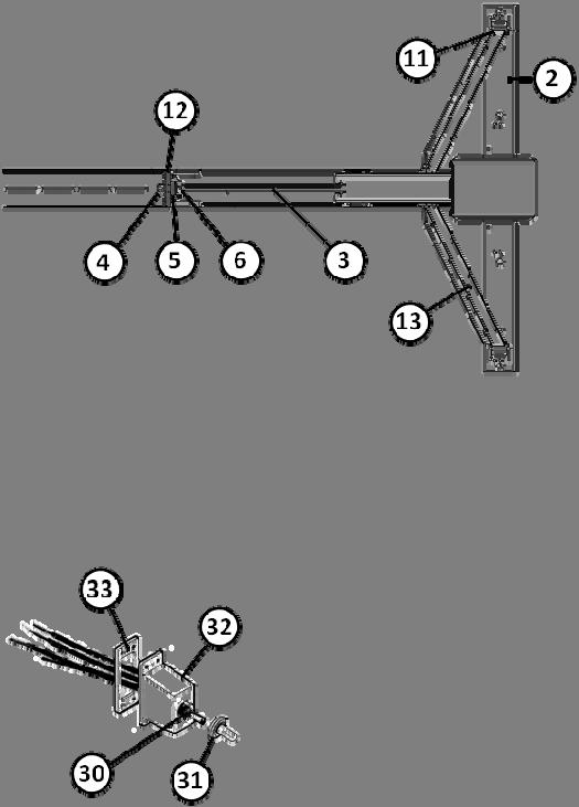
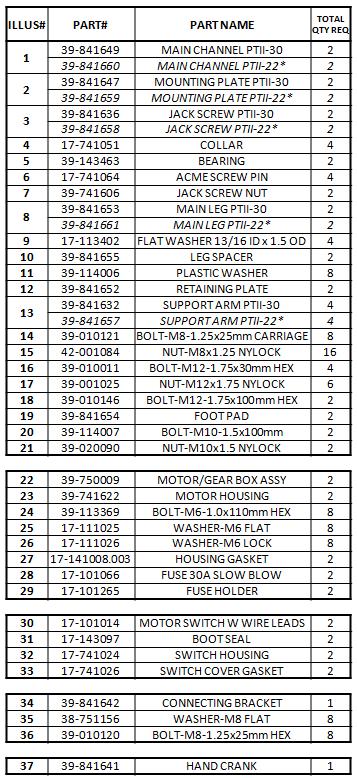
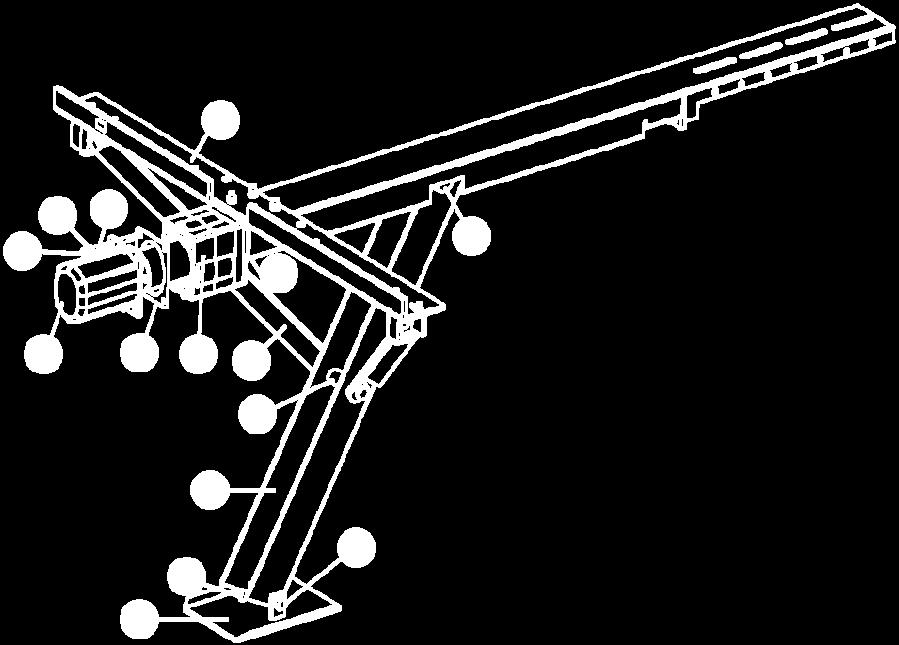
1 INSTALLATION/OPERATION ULTRA POWER TWIN II-30 P/N APPLICATION The primary purpose of your Power Twin II is to provide rock solid stabilization for maximum comfort while using your RV in a parked position. To obtain this desired end result and eliminate the possibility of damage to your RV or the Power Twin II, it is very important to follow these step by step instructions. IMPORTANT: DO NOT OPERATE THE POWER TWIN II BEFORE READING THE OPERATING INSTRUCTIONS. The Power Twin II will assist you in final lifting and leveling, based on the Power Twin II Power Curve Graph which shows pounds of lift in relation to the ground clearance from the bottom of the frame. By measuring the ground clearance on your RV you can determine the maximum amount of lift your Power Twin II will provide for final leveling. NOTE: THE POUNDS OF LIFT INCREASES AS THE DISTANCE, FROM GROUND TO FRAME, INCREASES. SAFETY AND DAMAGE WARNING CAUTION: ALWAYS FOLLOW THESE INSTALLATION AND OPERATING INSTRUCTIONS TO PREVENT DAMAGE TO YOUR RV AND TO PREVENT PERSONAL INJURY. INSTALLATION The Power Twin II 30 does not come assembled. Please follow all of the steps of these instructions. The Power Twin II 22 is pre assembled, so please skip to Step 3. ❶ Attach mounting plate (#2) to main assembly channel (#1) using four (4) M8 1.25x25mm carriage bolts (#14) and four (4) M8x1.25 NYLOCK nuts (#15). Make sure the mounting plate is square to the main channel assembly before tightening the nuts. ❷ Attach the two (2) arm support braces (#13) to the mounting plate (#2) using two (2) M x30mm hex head bolts (#16) and two (2) M12x1.75 NYLOCK nuts (#17). Place the plastic washer (#11) between the arm and the mounting bracket. Attach the other end of the arm support braces to the leg assembly (#8) using one (1) M x100mm hex head bolt (#18) and one (1) M12x1.75 NYLOCK nut (#17) by placing the leg spacer (#10) inside the leg assembly and pushing the bolt through the one side of the leg, through the spacer and out of the other side of the leg channel. Be sure to place the plastic washer (#11) between the arm and the leg brace before pushing the bolt through the hole. Tighten all bolts and nuts until snug. tighten as these are pivot points. Do not over REPEAT steps 1 and 2 for the second leg assembly ( PTII 30).
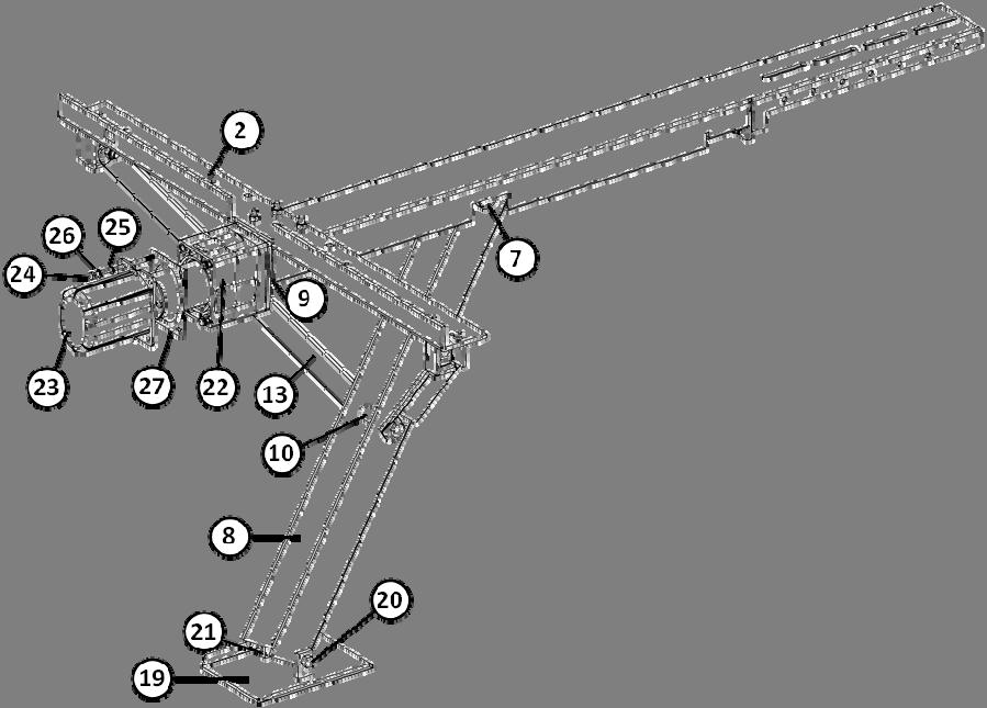
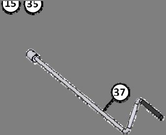
2 ❸ Measure the outside width of the main frame channel of your RV. Lay out the two (2) Power Twin leg assemblies (see figure in this section below) and adjust the inside distance between the two (2) mounting plates to the same as the outside dimension of your RV frame. Take the connecting bracket (#34) and position it over the two (2) side by side main channels (#1) and bolt by using eight (8) M8 1.25x25mm hex head bolts (#37) with the M8 flat washers (#36) and M8x1.25 NYLOCK nuts (#35). Do not tighten at this time. ❹ Attach the Power Twin assembly to the frame by using the holes provided in the mounting plate (#2) and (6 each side) ⅜ ***hex head bolts and nuts or ⅜ self drilling ***hex head screws. DO NOT use any fasteners smaller than ¼ diameter. ❺ To finish assembly, go back and tighten the eight (8) bolts and nuts at the connecting bracket (#34). ❻ Next step is to wire the switches to our motor assemblies and connect to the 12 volt power supply. NOTE: In some installations, to achieve the maximum stabilization you require, it may be necessary to support the connecting bracket to the frame of your RV. We do not supply the brackets as there are many different configurations of cross members and in most installations it is not necessary. ***hardware not included MOTOR INSTALLATION ❶ Attach each of the motor and gear box assemblies (#22) to the Power Twin II with the four (4) M6 1.0x110mm hex bolts (#24) making sure the gasket (#27) is between the motor cover and the gear box. NOTE: Make sure that the wires come out of the bottom side of the motor cover (towards the ground when installed). REPEAT this step for the second motor and gear box assembly. ❷ The switches may be mounted at any desired location, but a preferred location would be in a protected environment, such as a storage compartment or switch box near the jacks. THE GOAL: To be child proof as well as weather proof. ❸ CAUTION: To avoid short circuits, remove the fuses (#28) from the fuse holders (#29) until the wiring is complete. Use 10 gauge (supplied) wires for the install. Using a smaller gauge wire will void the warranty. Join all wire connections with solder connections or crimp type connection. DO NOT use wire nuts as they tend to loosen and fall off. ❹ Connect the GREEN wire to the negative terminal of the battery, or securely ground it to the frame (a clean and paint free area). ❺ Connect the WHITE wire to the positive terminal of the battery, or the nearest positive terminal block. Make sure to install the fuse holders (#29) on this WHITE wire, one on each switch. If running more than 15 feet of wire to access the battery, use a larger wire, such as 6 gauge wire. This will assure maximum performance. Voltage drop is a concern on long spans. ❻ Connect the BLACK wire from the motor to the BLACK wire of the switch. Connect the RED wire from the motor to the RED wire of the switch (on each motor). 2
.")
3 ❼ Replace the fuse (#28) and test the Power Twin II, one leg at a time. Check to see that the switches are wired in a logical relationship (UP position on the switch will raise the jack leg, DOWN position lower the jack leg). EMERGENCY HANDLE USAGE/MANUAL OPERATION ❶ Remove the fuses from the fuse holders. ❷ Remove the four (4) bolts (ITEM# 24) holding the motor in place. ❸ Place the pinned collar drive on the handle over the slotted collar and turn the crank the appropriate direction to either extend the Power Twin II leg or retract it. INSTRUCTIONS FOR USE TRAVEL TRAILER OR 5 TH WHEELS ❶ Chock your wheels and level your RV from front to back by using your tongue jack or landing gear. ❷ Using a level, determine which side of our RV is the lowest and extend the jack(s) on that side until your RV is level. ❸ Extend the jack(s) on the opposite side of the RV until they touch the ground firmly. Your RV is now in its most stable position. ❹ You can retract all of the jacks simultaneously. CLASS C MOTOR HOMES ❶ Set your brakes. ❷ Extend the jack on the low side of your Class C motor home until the rear is level. ❸ Extend the opposite side until it touches the ground firmly. Your RV is now in its most stable position. LUBRICATION CAUTION: ALWAYS RETRACT POWER TWIN II BEFORE DEPARTING. Each motor/gear assembly should be re greased once per year through the grease fitting on the gearbox. WARNING: DO NOT USE pneumatic powered lube equipment as it can damage the leveler unit. Use hand operated grease gun only. Two pumps of chassis lube once per year is all that should be required. DO NOT over fill the gearbox with chassis lube as it could push into the motor causing damage to the motor.

4
5 THREE YEAR LIMITED WARRANTY DELUXE 5 TH WHEEL LANDING GEAR, ULTRA SWAY CONTROL, WEIGHT DISTRIBUTION HITCH, BALL MOUNTS, HITCH BALLS, ODYSSEY 3000/4000 TONGUE JACKS, POWERTWIN II STABILIZERS, THE ELIMINATOR STABILIZER, LEVELING BLOCKS AND MANUAL TONGUE JACKS THE MANUFACTURER NAMED BELOW MAKES THE FOLLOWING WARRANTY WITH RESPECT TO THE ABOVE ULTRA FAB PRODUCTS 1. This Warranty is made only to the first Purchaser (hereinafter called the Original Purchaser ) who acquires this product for their own use. 2. This Warranty will be in effect for three years from the date of purchase by the Original Purchaser. It is suggested that the Original Purchaser retain a copy of the dated bill of sale as proof of the date of purchase. 3. This Warranty covers only specified parts which shall be free from defects in material and workmanship under normal use. This Warranty does not cover conditions unrelated to the material and workmanship of the product. Such unrelated conditions include, but are not limited to (a) faulty installation and any damage resulting from such; (b) the need for normal maintenance and any damage resulting from the failure to provide such maintenance; (c) failure to follow Manufacturer s instructions for use of this product, and (d) any accident to, or misuse of, any part of this product and any alteration by anyone other than the Manufacturer or its authorized representative. 4. In order to obtain the benefits of this Warranty, you should return the product which you find defective to the Manufacturer named below during the period that this Warranty is in effect. All charges incurred in delivery of the product to the Manufacturer, and in picking it up after the Warranty service has been completed, must be paid by the Original Purchaser. 5. Any item returned in the manner described in paragraph 4 will be examined by the Manufacturer. If it is found that the returned item was defective in material or workmanship, the Manufacturer will repair it without charge for material and labor. 6. Ultra Fab will pay freight on replacement parts during the first 90 days of ownership by the Original Purchaser. 7. The Manufacturer does not authorize any person or company to create any Warranty obligation or liability on their behalf. 8. IN NO EVENT SHALL THE MANUFACTURER BE LIABLE FOR INCIDENTAL OR CONSEQUENTIAL DAMAGES. SOME STATES DO NOT ALLOW THE EXCLUSION OR LIMITATION OF INCIDENTAL OR CONSEQUENTIAL DAMAGES SO THE ABOVE LIMITATION OR EXCLUSION MAY NOT APPLY TO YOU. 9. ANY IMPLIED WARRANTY, INCLUDING THE IMPLIED WARRANTY OF MERCHANTABILITY AND FITNESS FOR ANY PURPOSE, IS LIMITED TO THE DURATION OF THIS LIMITED WARRANTY. SOME STATES DO NOT ALLOW LIMITATIONS ON HOW LONG AN IMPLIED WARRANTY LASTS, SO THE ABOVE LIMITATION MAY NOT APPLY TO YOU. 10. THIS WARRANTY GIVES YOU SPECIFIC LEGAL RIGHTS, AND YOU MAY ALSO HAVE OTHER RIGHTS WHICH VARY FR0M STATE TO STATE SR 19 S., Elkhart, IN Tel: (574) Fax: (574) fab.com
ULTRA WEIGHT DISTRIBUTING HITCH SYSTEM INSTALLATION/OPERATION INSTRUCTIONS
 ULTRA-FAB PRODUCTS, INC. 57985 St. Rd. 19 South, Elkhart, Indiana 46517 ULTRA WEIGHT DISTRIBUTING HITCH SYSTEM ULTRA WEIGHT DISTRIBUTING HITCH SYSTEM INSTALLATION/OPERATION INSTRUCTIONS ITEM # 1 EXPLODED
HANDY GATE ASSEMBLY, INSTALLATION AND OPERATING INSTRUCTIONS
 ASSEMBLY, INSTALLATION AND OPERATING INSTRUCTIONS BEFORE INSTALLING OR USING THE, REVIEW THE VEHICLE LOADING LIMITATIONS OUTLINED IN THE VEHICLE OWNER S MANUAL AND THE SAFETY COMPLIANCE CERTIFICATION LABEL
INSTALLATION INSTRUCTIONS
 INSTALLATION INSTRUCTIONS Thank you for purchasing ROXTERTM Hitch Mounted Mud Flaps. Agri-Cover, Inc. proudly manufactured these mud flaps using superior quality materials and workmanship. With proper
Installation Instructions Soft Top Replacement Hardware, Wrangler
 Installation Instructions Soft Top Replacement Hardware, 87-95 Wrangler IMPORTANT NOTICE: Carefully read instructions before attempting to install this product. Rampage is in no way responsible for any
Instruction Manual 15K - Fifth Wheel Hitch Part Number 6030 & 6031
 DEALER/INSTALLER: (1) Provide this Manual to end user. (2) Physically demonstrate hitching and unhitching procedures in this Manual to end user. (3) Have end user demonstrate that he/she understands procedures.
Installation Instructions
 Equipment Required: Fastener Kit: F Wrenches: 15/16, 15/16 Crowfoot Adaptor Drill Bits: 1/4 Other Tools: Drill, Reciprocating saw Optional, Raise Bed: 18mm socket, 15 extension As an option you can loosen
Installation Instructions Receiver Rack (Part # 7700) Universal Application
 Universal Application") NOTE: Carefully read entire instructions thoroughly before attempting to install this part. Parts Included Qty Tools Needed 2 Draw Bar 1 Ratchet Racks 2 Socket Set Curved Support Bars 2 Wrench Set Connecting
NOTE: Carefully read entire instructions thoroughly before attempting to install this part. Parts Included Qty Tools Needed 2 Draw Bar 1 Ratchet Racks 2 Socket Set Curved Support Bars 2 Wrench Set Connecting
16K and 19K Sidewinder TM Service Kit Instructions 86005
 86005 Equipment Required: Wrenches: 15/16, 1 1/8, Torque Wrench, Rubber Mallet Included Service Kit Items: 1 Qty. (1) Wear Plate 2 Qty. (6) 5/8 Conical Washer 3 Qty. (2) Wedge Bolt, 5/8-11 X 1 3/4 GRD
INSTRUCTION MANUAL TITAN 16K - Fifth Wheel Hitch Plymouth MI
 You can take it with you. INSTRUCTION MANUAL TITAN 16K - Fifth Wheel Hitch Plymouth MI Product No. 30866 DEALER/INSTALLER: END USER: (1) Provide this Manual to end user. (2) Physically demonstrate hitching
Installation Instructions SRC Over-Size Tire Carrier Jeep Wrangler/Unlimited Part # 2743
 NOTE: Carefully read instructions entirely before assembling/installing this product. Parts Included Qty Parts Included Qty Tire Carrier 1 8 x 70mm Hex Bolt 4 Brake Light Bracket 1 8mm Flat Washer 4 Tire
Instruction Manual 30K - Fifth Wheel Hitch Part Number 30054
 You can take it with you. ELKHART, IN., OAKVILLE, ONT. Instruction Manual 30K - Fifth Wheel Hitch Part Number 30054 DEALER/INSTALLER: (1) Provide this Manual to end user. (2) Physically demonstrate hitching
Gooseneck Hitch Ball plate with 2-5/16" ball spins in/out 30,000 lb. rating. (5,000 lb. vertical load) Requires only one 3" hole in truck bed
 Requires only one 3 hole in truck bed") OWNER'S MANUAL 18,000 lb. rating (3,500 lb. vertical) No towing hardware in your bed when you don t need it. Easy on/off design No drilling into your truck frame Side-to-side pivot of 10 degrees Gooseneck
OWNER'S MANUAL 18,000 lb. rating (3,500 lb. vertical) No towing hardware in your bed when you don t need it. Easy on/off design No drilling into your truck frame Side-to-side pivot of 10 degrees Gooseneck
E5 5 th Wheel Hitch Assembly
 E5 5 th Wheel Hitch Assembly 1. Hitch Handle Assembly a) Rotate the handle shaft so the bolt hole is oriented at the top. b) Hold the handle with the grip pointed downward and slide the handle onto the
Installation Instructions
 Installation Instructions AMP RESEARCH Power Step by Bestop Automatic Retracting Running Board Vehicle Application Nissan Titan King Cab 2004 and newer (5 ft.) Part Number: 75106-01 Nissan Titan Crew Cab
5 th Airborne Sidewinder Service Kit Instructions 94316
 94316 Equipment Required: Wrenches: 15/16, Torque Wrench, Rubber Mallet 3 4 5 2 Included Service Kit Items: 1 Qty. (1) Wear Plate 2 Qty. (1) Wear Bushing 3 Qty. (1) Wear Disc 4 Qty. (4) 5/8-11x2 GRD8 Bolt
COVER PAGE CUSTOM QUICK INSTALL MOUNTING KIT NOTE!
 COVER PAGE NOTE! Prior to installing product, please visit one of our websites to assure your kit contains the most recent revision to installation instruction and verify vehicle application. www.reeseproduct.com
Installation Instructions
 Equipment Required: Installation Instructions Fastener Kit: F Wrenches: 15/16, 10 mm Drill Bits: 1/4 Other Tools: Drill, Reciprocating Saw 9464/9474 HIDE-A-GOOSE HITCH All Fasteners Typical, Both Sides
Installation / Owners Manual
 DEALER/INSTALLER: (1) Provide this Manual to end user END USER: Part Number: 94621 94622* *Packaged for Individual sale. (1) Read and follow this Manual for Reese Installation. (2) Save this Manual for
Utility Jack Model Number: HD HD HD
 Utility Jack Model Number: 74407 74407HD 74410 74410HD 74413 74413HD 74412 74415 70429 Rolled Acme Thread and Anti-Friction thrust Bearings High Strength Tubing This Instruction Sheet contains IMPORTANT
Installation Instructions
 Installation Instructions CUSTOM QUICK INSTALL MOUNTING KIT 2011 & UP Ford Super Duty F-250/F-350/F-50 2011 & UP Part Number: 50073 WARNING: Under no circumstances do we recommend exceeding the towing
Installation Instructions GOOSENECK MOUNTING KIT Chevrolet/GMC 1500/2500/3500 All except 4-door Crew-Cab
 GOOSENECK MOUNTING KIT Equipment Required: Fastener Kit: F Wrenches: 3/4, 7/8, 15/16 Drill Bits: 1/4 Other Tools: Drill WARNING: Under no circumstances do we recommend exceeding the towing vehicle manufacturers
INSTALLATION/OPERATION
 INSTALLATION/OPERATION PHOENIX 4000 ELECTRIC TONGUE JACK INSTALLATION 1. Block the wheels and support the trailer A frame securely. 2. Remove the existing jack. NOTE: Save the original nuts, bolts, and
Installation Instructions
 Installation Instructions Application Fits 2011-2014 Subaru Impreza WRX Sedan X7279 & X7280 DOES NOT FIT HATCHBACK MODEL 2 & 1.25 EcoHitch Invisi 200 lbs. Tongue Weight/2,000 lbs Weight Carrying Torklift
AEROMOTIVE Part # INSTALLATION INSTRUCTIONS
 AEROMOTIVE Part # 16303 INSTALLATION INSTRUCTIONS CAUTION: Installation of this product requires detailed knowledge of automotive systems and repair procedures. We recommend that this installation be carried
Installation Instructions
 Installation Instructions Application Fits 2014+ BMW i3 X7277 & X7278 2 & 1.25 Stealth EcoHitch 200 lbs. Tongue Weight NOT RATED FOR TOWING Torklift Central 315 Central Ave N Kent, WA 98032 253-854-1832
20K - Fifth Wheel Hitch
 You can take it with you. INSTRUCTION & OPERATION MANUAL 20K - Fifth Wheel Hitch DEALER/INSTALLER: (1) Provide this Manual to end user. (2) Physically demonstrate hitching and unhitching procedures in
Installation Instructions 1.25 EcoHitch Stealth
 Installation Instructions 1.25 EcoHitch Stealth Application Fits Tesla Roadster 1.5 (2008) Tesla Roadster 2.0 & Roadster Sport 2.0 (2010) Tesla Roadster 2.5 & Roadster Sport 2.5 (2011) X7198 Gross Tongue
Installation Instructions
 Installation Instructions Application Fits 2013-2014 BMW X5 X7265 2013-2014 BMW 500 lbs. Tongue Weight/5,000 lbs Weight Carrying X5 2 EcoHitch Invisi Torklift Central 315 Central Ave N Kent, WA 98032 253-854-1832
Installation Instructions
 Equipment Required: Fastener Kit: F Wrenches: 15/16, 10 mm Drill Bits: 1/4 Other Tools: Drill, Reciprocating Saw 9464/9474 HIDE-A-GOOSE HITCH INSTALLATION All Fasteners Typical, Both Sides WARNING: Under
Installation Instructions
 Equipment Required: Fastener Kit: F Wrenches: 15/16, 15/16 Crowfoot Adaptor Drill Bits: 1/4 Other Tools: Drill, Reciprocating saw Optional, Raise Bed: 18mm socket, 15 extension As an option you can loosen
Installation Instructions
 Installation Instructions Rock Crawler Roof Rack (Part # 76717) 07-Up Jeep Wrangler J/K 4Door For Technical Support/Warranty Information please call 310-762-9944 Smittybilt, 400 West Artesia Blvd, Compton,
R20 - Fifth Wheel Hitch
 You can take it with you. INSTRUCTION MANUAL R20 - Fifth Wheel Hitch Plymouth MI Product No. 30867 DEALER/INSTALLER: END USER: (1) Provide this Manual to end user. (2) Physically demonstrate hitching and
Installation Instructions
 Installation Instructions Application Fits 2015+ Volkswagen Golf R X7332 & X7333 2 & 1.25 EcoHitch Stealth 200 lb. Tongue Weight/ 2,000 lb. Towing Weight HICKNESS LENGTH Torklift Central 315 Central Ave
Installation Instructions
 Equipment Required: Fastener Kit: F Wrenches: 3/4, 15/16, 10mm, 18mm Drill Bits: 1/4 Other Tools: Drill, Reciprocating saw 9465/9475 HIDE-A-GOOSE HITCH INSTALLATION All Fasteners Typical, Both Sides WARNING:
INSTALLATION INSTRUCTIONS
 INSTALLATION INSTRUCTIONS Thank you for purchasing ROLTECTM Electric Hopper Conversion. Agri-Cover, Inc. proudly manufactured this hardware using superior quality materials and workmanship. With proper
Installation Instructions
 Installation Instructions Application Fits 2015 Volkswagen Golf Sportwagen X7315 & X7316 2 & 1.25 EcoHitch Stealth 200 lb. Tongue Weight/ 2,000 lb. Towing Weight L THICKNESS LENGTH Torklift Central 315
INSTRUCTION MANUAL 22K - Fifth Wheel Hitch
 You can take it with you. INSTRUCTION MANUAL 22K - Fifth Wheel Hitch Product No. 30033 DEALER/INSTALLER: (1) Provide this Manual to end user. (2) Physically demonstrate hitching and unhitching procedures
Installation Instructions
 85-3910 rev. 03 01-18 Installation Instructions Thank you for purchasing the antisway bar kit. Please read through these instructions before installation. Rear Anti-Sway Bar Kit for Ford F-250/F-350 part
Installation Instructions
 Equipment Required: Fastener Kit: F Wrenches: 3/4, 15/16 Drill Bits: 1/4 Other Tools: Drill, Reciprocating saw WARNING: Under no circumstances do we recommend exceeding the towing vehicle manufacturers
Installation Instructions
 85-3180 rev. 07 03-14 Installation Instructions Thank you for purchasing this antisway bar kit. Please read through these instructions before installation. Front Anti-Sway Bar Kit for the Ford E350/450
CSA CERTIFIED Conforms to UL 507
 Installation tion Instructions Please read and save these instructions! TURBO/MAXX12 Volt All Weather RV Ventilator Fans P/N 00-965001 Deluxe Model 1200T WITH THERMOSTAT P/N 00-965007 Standard Model 3550
Installation Instructions
 85-3700 rev. 08 05-18 Installation Instructions Thank you for purchasing this antisway bar kit. Please read through these instructions before installation. Front Anti-Sway Bar Kit for the F53 Chassis part
Installation Instructions Application Fits 2016 Tesla Model X The Law Removable License Plate Frame X7340
 Installation Instructions Application Fits 2016 Tesla Model X The Law Removable License Plate Frame X7340 Parts Inventory Item Image Item Description Quantity Grill Bracket 1 License Plate Bracket 1 1
Installation Instructions
 Installation Instructions ELECTRIC CONVERSION KIT 3 ALUMINUM ROLL TUBE IMPORTANT: This Electric Conversion Kit has been designed for systems with a 3 aluminum roll tube. It is assumed that the tarping
Installation Instructions GOOSENECK MOUNTING KIT Toyota Tundra
 GOOSENECK MOUNTING KIT Toyota Tundra 446 Equipment Required: Fastener Kit: 446F Wrenches: 10mm, 1mm, /4, 7/8, 15/16 Drill Bits: 1/4 Other Tools: Drill WARNING: Do not store hitch ball upside down in head.
Installation Instructions
 Equipment Required: Fastener Kit: F Wrenches: 3/4, 15/16, 13mm Drill Bits: 1/4, some older models a 1/2 Other Tools: Drill, Saber Saw 5/8 Fasteners From Hitch Fastener Kit Installation Instructions GOOSENECK
Installation Instructions
 85-3511 rev. 04 11-15 Installation Instructions Polyurethane Bushing Kit for Ford F-53 (Front) (replaces OE bushings and brackets) part #4139-127 1-5/8 diameter INTRODUCTION Thank you for purchasing this
Installation Instructions
 Installation Instructions Application Fits 2016 Honda HR-V X7322 & X7323 2 & 1.25 EcoHitch Stealth 200 lb. Tongue Weight/ 2,000 lb. Towing Weight Torklift Central 315 Central Ave N Kent, WA 98032 253-854-1832
Installation Instructions
 Installation Instructions Application Fits 2012 + Toyota Prius V X7192 & X7193 2 & 1.25 EcoHitch Stealth 350 lbs. Tongue Weight/ 3,500 lbs. Towing Weight Torklift Central 315 Central Ave N Kent, WA 98032
Installation Instructions
 Installation Instructions Automatic Retracting Running Board Vehicle Application Ford F150 Supercrew 2001-2003 (2004 Heritage) Part Number: 75111-01 www.bestop.com - We re here to help! Visit our web site
Installation Instructions
 Sidewinder Turret TM Part Number: 61300 DEALER/INSTALLER: (1) Provide this Manual to end user END USER: (1) Read and follow this Manual for Sidewinder Turret Installation. (2) Save this Manual for Future
Installation Instructions
 85-3847 rev. 01 09-09 Installation Instructions Thank you for purchasing this anti-sway bar kit. Please read through these instructions before installation. Front Anti-Sway Bar TruTrac Bar Combo Kit for
Installation Instructions
 Installation Instructions Application Fits 2012-2015 Honda Honda CR-V X7297 & X7298 2 & 1.25 EcoHitch Stealth 350 lb. Tongue Weight/ 3,500 lb. Towing Weight Torklift Central 315 Central Ave N Kent, WA
Installation Instructions
 Equipment Required: Fastener Kit: F Wrenches: 3/4, 15/16, 13mm Drill Bits: 1/4, some older models a 1/2 Other Tools: Drill, Saber Saw 5/8 Fasteners From Hitch Fastener Kit Installation Instructions GOOSENECK
This sheet must be read completely to:
 Instalation Preparation This sheet must be read completely to: 2. Avoid causing injury to installer, customer, end user, or others. 3. Prevent damage to ATV, UTV, and Motorcycle and/or accessory. 4. Prevent
Installation Instructions
 85-4209 rev. 05 11-18 Installation Instructions Thank you for purchasing this anti-sway bar kit. Please read through these instructions before installation. Factory Replacement Anti-Sway Bar Kit part #1129-135
**DO NOT EXCEED RECOMMENDED VEHICLE TOWING WEIGHT!** FORD F-250, F-350
 6065 SUBKIT 7/7/0 **DO NOT EXCEED RECOMMENDED VEHICLE TOWING WEIGHT!** FORD F-50, F-50 PAGE OF WARNING!! BRAKE, FUEL, AND ELECTRICAL LINES MAY NEED TO BE LOOSENED OR REPOSITIONED TO PROVIDE CLEARANCE FOR
Installation Instructions **THIS RAIL MOUNTING KIT USES 11 BOLTS**
 Installation Instructions CUSTOM QUICK INSTALL MOUNTING KIT FORD SUPER DUTY Part Numbers: 50074 WARNING:Under no circumstances do we recommend exceeding the towing vehicle manufacturers recommended vehicle
**DO NOT EXCEED RECOMMENDED VEHICLE TOWING WEIGHT!** FORD F-250, F-350
 60647 SUBKIT 7/3/204 **DO NOT EXCEED RECOMMENDED VEHICLE TOWING WEIGHT!** FORD F-250, F-350 PAGE OF 4 WARNING!! BRAKE, FUEL, AND ELECTRICAL LINES MAY NEED TO BE LOOSENED OR REPOSITIONED TO PROVIDE CLEARANCE
Installation Instructions
 Equipment Required: Installation Instructions Fastener Kit: F Wrenches: 8mm, 13mm, 3/4, 15/16 Drill Bits: 1/4 Other Tools: Drill, Reciprocating Saw, File WARNING: Under no circumstances do we recommend
REPLACING ROLTEC SPRING ARMS
 REPLACING ROLTEC SPRING ARMS NOTICE TO INSTALLER: Even if familiar with hardware, read instructions prior to installation as improvements may be made without notice. Always handle components with care.
16K Revolution Service Kit Instructions 86016
 86016 Equipment Required: Wrenches: 15/16, 1 1/8, Torque Wrench, Rubber Mallet Included Service Kit Items: 1 Qty. (1) Wear Plate 2 Qty. (1) Pivot Bushing 3 Qty. (1) Bearing Cup 4 Qty. (1) Bearing 1 5 Qty.
INSTALLATION INSTRUCTIONS AND OWNER S MANUAL
 INSTALLATION INSTRUCTIONS AND OWNER S MANUAL Thank you for purchasing ADARAC Truck Bed Rack. Agri-Cover, Inc. proudly manufactured this product using superior quality materials and workmanship. With proper
A S S E M B L Y I N S T R U C T I O N S
 A S S E M B L Y I N S T R U C T I O N S Please Do Not Return This Product to the Store! Contact Escalade Sports customer service department at: Phone: 1-888-USA-GOAL Toll-Free! Fax: 1-866-873-3536 Toll-Free!
Installation Instructions
 85-4592 rev. 08 02-18 Installation Instructions Thank you for purchasing our sway bar kit. Please read through these instructions before installation. Auxiliary Rear Anti-Sway Bar Kit for Ford F53 part
INSTALLATION INSTRUCTIONS MOUNTING KIT FOR ELITE SERIES
 INSTALLATION INSTRUCTIONS MOUNTING KIT FOR ELITE SERIES DEALER/INSTALLER: (1) Provide this Manual to end user. END USER: (1) Save this Manual for future reference. (2) Pass on copies of Manual to any other
Installation Instructions
 Equipment Required: Fastener Kit: F Wrenches: 3/4, 15/16 Drill Bits: 1/4 Other Tools: Drill Short & Long Bed All Megacabs 9464/9474 HIDE-A-GOOSE HITCH INSTALLATION WARNING: Under no circumstances do we
Installation Instructions
 Equipment Required: Installation Instructions Fastener Kit: F Wrenches: 8mm, 13mm, 3/4, 15/16 Drill Bits: 1/4 Other Tools: Drill, Reciprocating Saw, File WARNING: Under no circumstances do we recommend
Installation Instructions
 Equipment Required: Installation Instructions Fastener Kit: F Wrenches: 3/4, 15/16 Drill Bits: 1/4 Other Tools: Drill WARNING: Under no circumstances do we recommend exceeding the towing vehicle manufacturers
Safety Sentry Electronic Breakaway Switch
 Safety Sentry Electronic Breakaway Switch P-616-WE 819-0454 Installation Instructions An Altra Industrial Motion Company Parts List Mounting hardware included with the Safety Sentry Breakaway Switch kit:
Installation Instructions
 Equipment Required: Fastener Kit: F Wrenches: 3/4, 15/16 Drill Bits: 1/4 Other Tools: Drill WARNING: Under no circumstances do we recommend exceeding the towing vehicle manufacturers recommended vehicle
Instruction Sheet SRSR SERIES. Rotating Sliding Rail System
 Instruction Sheet SRSR SERIES Rotating Sliding Rail System THANK YOU Thank you for purchasing the SRSR Series Rotating Sliding Rail System. Please read these instructions thoroughly before assembling this
INSTRUCTION MANUAL 16K - Fifth Wheel Hitch
 You can take it with you. INSTRUCTION MANUAL 16K - Fifth Wheel Hitch Plymouth MI Product No. 30047 DEALER/INSTALLER: END USER: (1) Provide this Manual to end user. (2) Physically demonstrate hitching and
Joy Rider Shock System Installation
 Joy Rider Shock System Installation Manufacturer s Part Numbers: 3 Inch Single Axle 200103 UPC 784672350945 2⅜ Inch Single Axle 200102 UPC 784672350921 Each single axle kit contains the following: 2 Shock
Seat Track Slide Installation Instructions
 Seat Slide Installation Instructions For: All Jeep CJ5s, CJ7s and Wranglers 1976-1995 Part Number: 51255 Jeep is a registered trademark of Chrysler and Bestop is not affiliated with Chrysler Corporation.
Fig Series. Installation and Spare Parts Manual Pilot House Control Solar-Ray Sealed Beam 7 & 8 Searchlights
 Fig. 0314 Series Installation and Spare Parts Manual Pilot House Control Solar-Ray Sealed Beam 7 & 8 Searchlights 16490 N.W. 13th Avenue Miami, FL 33169-5707 www.perko.com 0314PTD5 Rev: 9/2016 Fig. 0314
RV Stabi-Lizer Installation & Operation Manual Effective May 2018
 RV Stabi-Lizer Installation & Operation Manual Effective May 2018 Contents Installation Pages 2 & 3 Operation Page 4 Manual override Page 5 Drawings Page 6 & 7 Warranty Page 8 Tools required for installation
Installation Instructions
 Installation Instructions Automatic Retracting Running Board Vehicle Application Dodge Ram Quad Cab Pickup 2002-2005 Part Number: 75101-01 Dodge Ram Mega Cab Pickup 2006 - Current Part Number: 75118-01
Installation Instructions
 85-4341 rev. 04 10-15 Installation Instructions Thank you for purchasing this antisway bar kit. Please read through these instructions before installation. Rear Anti-Sway Bar Kit for Chevy 2500/3500/4500
Dodge Ram 1500, Quad/Reg. Cab, w/6.4ft. & 8ft. Bed, 2 & 4 WD. For updates see PRODUCT SUPPORT tab at
 Assembly, Installation, Operation and Maintenance Instructions 2009-2016 Dodge Ram 1500, Quad/Reg. Cab, w/6.4ft. & 8ft. Bed, 2 & 4 WD. Part # 30665 Dealer / Installer: Provide a copy of these Instructions
INSTALLATION INSTRUCTIONS MOUNTING KIT COMMERCIAL TRUCK FOR 34 OUTSIDE FRAME WIDTH ONLY. Front of vehicle
 INSTALLATION INSTRUCTIONS MOUNTING KIT COMMERCIAL TRUCK FOR 34 OUTSIDE FRAME WIDTH ONLY DEALER/INSTALLER: (1) Provide this Manual to end user. END USER: (1) Save this Manual for future reference. (2) Pass
RAM 1500, 2019 CLASSIC & 2010-ON 2500/3500 INSTALLATION INSTRUCTIONS
 2009-18 RAM 1500, 2019 CLASSIC & 2010-ON 2500/3500 INSTALLATION INSTRUCTIONS Thank you for purchasing ROCKSTARTM Splash Guard Mud Flaps. Agri-Cover, Inc. proudly manufactured these mud flaps using superior
MLS KICK-OFF TABLETOP SOCCER TABLE ASSEMBLY INSTRUCTIONS
 MLS KICK-OFF TABLETOP SOCCER TABLE ASSEMBLY INSTRUCTIONS NGD1028 1 THANK YOU! Thank you for your purchase of this Harvil product. We work around the clock and around the globe to ensure that Harvil products
PIAA Multi-Fit 005/1100X Light Bracket Kits
 ENGLISH PIAA Multi-Fit 005/1100X Light Bracket Kits Thank you for your purchase. Please read all the instructions before beginning.! WARNING Lighting laws vary state to state, check your local laws before
Installation Instructions READ THOROUGHLY BEFORE BEGINNING Signature Series Rail Kit Dodge Ram Trucks-all, including Mega-cabs
 INDEX Failure to follow all of these instructions may result in death or serious injury!. GUIDELINES FOR MATCHING TOW VEHICLE AND TRAILER. Pages -. DRILLED AND BOLTED INSTALLATION FIGURE. Page 4. NO-DRILL,
13100 INSTALLATION INSTRUCTIONS
 00 INSTALLATION INSTRUCTIONS Safety glasses should be worn at all times while installing this product. YEARS: 0-PRESENT MAKE: FORD MODEL: EXPLORER STYLE: SUV WARNING: NEVER EXCEED YOUR VEHICLE MANUFACTURER'S
Installation Instructions
 85-5029 rev. 03 06-17 Installation Instructions Thank you for purchasing our anti-sway bar kit. Please read through these instructions before installation. Rear Anti-Sway Bar Kit for Workhorse W22, Holiday
Installation Instructions PowerBoard Automatic Retracting Running Board WARNING WARNING WARNING. Support
 Installation Instructions PowerBoard Automatic Retracting Running Board Vehicle Application: Jeep Wrangler 2-Door 2007-2016 Part Number 75651-15 Installation Tips Read and follow, precisely, all installation
Installation Instructions
 85-3195 rev. 12 04-18 Installation Instructions Thank you for purchasing this antisway bar kit. Please read through these instructions before installation. Part #1139-117 Rear Anti-Sway Bar Kit 1½ diameter
Hi-Rise 18K 5TH WHEEL CONVERSION HITCH
 ASSEMBLY INSTRUCTIONS Hi-Rise 18K 5TH WHEEL CONVERSION HITCH DEALER/INSTALLER: (1) Provide this Manual to end user. END USER: (1) Read and follow this Manual every time you use Hitch. (2) Save this Manual
Stainless Steel Outboard Motor Brackets - Installation and Operating Instructions Models T10054 and T10055
 USER MANUAL OUTBOARD MOTOR BRACKETS Stainless Steel Outboard Motor Brackets - Installation and Operating Instructions Models T10054 and T10055 CAUTION Do not exceed the bracket s HP or weight limits. Read
PATRIOT LIFT CO. ON-Lift Installation Guidelines
 PATRIOT LIFT CO. ON-Lift Installation Guidelines Choosing A Landing Gear Type It is important to note that the Patriot Lift Systems operates more efficiently for speed /timing with some landing gear types
AIR CONTROL ACCESSORY KIT
 RAPID RESPONSE SYSTEM 2283 AIR CONTROL ACCESSORY KIT INSTALLATION INSTRUCTIONS Congratulations on your purchase of a new Air Control Accessory Kit. This kit was designed to provide inflation control of
POWER GEAR SLIDE-OUT MANUAL
 POWER GEAR SLIDE-OUT MANUAL Operation Guide FLUSH FLOOR SLIDE-OUT SYSTEM FOR AMERICAN COACH PRODUCTS 82-S0220-01 Rev. 1 AMERICAN COACH SLIDE-OUT MANUAL FLUSH FLOOR SYSTEM TABLE OF CONTENTS SECTION PAGE
Installation Instructions
 85-3207 rev. 03 05-06 Installation Instructions Thank you for purchasing this anti-sway bar kit. Please read through these instructions before installation. Rear Anti-Sway Bar Kit for the Freightliner
Single Leg AM/CM 20, 24 and 30
 800/846-9659 www.equalizersystems.com Installation and Operation Guide April 2007 Single Leg AM/CM 20, 24 and 30 Installation Tools Required for Installation Ratchet, sockets and wrench set Wire cutters/crimpers
20K - Fifth Wheel Hitch
 You can take it with you. INSTRUCTION & OPERATION MANUAL 20K - Fifth Wheel Hitch DEALER/INSTALLER: (1) Provide this Manual to end user. (2) Physically demonstrate hitching and unhitching procedures in
TAILGATE SPREADER INSTALLATION & OWNER S MANUAL TABLE OF CONTENTS
 A Division of Northern Star Industries, Inc. P.O. Box 788 Iron Mountain MI 49801-0788 www.bossplow.com SMARTHITCH 1100 TAILGATE SPREADER INSTALLATION & OWNER S MANUAL TABLE OF CONTENTS S & CAUTIONS...
INSTALLATION INSTRUCTIONS MOUNTING KIT FOR ELITE SERIES
 INSTALLATION INSTRUCTIONS MOUNTING KIT FOR ELITE SERIES DO NOT EXCEED VEHICLE MANUFACTURER S RATING FOR 5th WHEEL TOWING OR MAXIMUM GROSS TRAILER WEIGHT OF 18,000lb. / 8160kg. DEALER/INSTALLER: (1) Provide
MOTORIZED FOLDING CAMPER WINCH
 OWNER'S MANUAL MOTORIZED FOLDING CAMPER WINCH With 1200lb Lift Capacity The 12 Volt Motorized Folding Camper Winch is used to raise and lower folding campers with the touch of the switch, eliminating hand