Slinky Long Travel Suspension. Toyota Land Cruiser. 80 Series Installation Instructions
|
|
|
- Amy Lester
- 6 years ago
- Views:
Transcription

1 Slinky Long Travel Suspension Toyota Land Cruiser 80 Series Installation Instructions
2 Table of Contents Tools Required... 4 Overview... 5 Torque Specs... 5 Step 1 - The Basics... 6 Step 2 - Penetrating Oil on Anything to Remove... 6 Step 3 - Remove Bump Stops and Sway Bar Brackets... 6 Step 4 - Shock Removal... 7 Step 5 - Rear Brake Line Removal and Installation... 7 Step 6 - Remove Rear Axle Breather Hose... 8 Step 7 - Spring Removal... 8 Step 8 - Coil Install... 9 Step 9 - Install the Shocks Step 10 - Install the Sway Bar Links Step 11 - Remove Old Front Shocks and Loosen Radius Arm Nuts Step 12 - Remove the Radius Arms Step 13 - Remove Cater Bushings (OEM) for New Caster Bushings Step 14 - Washer Mod / Caster / Plate Mods Step 15 - Install Radius Arms Step 16 - Install the Front Coils Step 17- Install Front Shocks Step 18 - Remove and Install Pan Hard Rods Step 19 Remove & Install Front Brake Lines Step 20 - Bleed Brake System Step 21 - Adjust Drag Link Step 22 - Install Front Sway Bay Drop Brackets Step 23 Complete! Figures / Images Figure 1 - Bump stops Figure 2 - Rear factory brake line to be replaced Figure 3 Rear sway bar drop bracket Figure 4 Rear upper shock mounting plate Figure 5 Shock mount bolt Figure 6 Stud bolts Figure 7 - Tap lower shock mount
3 Figure 8 Install shock Figure 9 Lower shock mount rock shields Figure 10 Stage 4 shock pin set up Figure 11 Install bump stops Figure 12 Rear sway bar mount Figure 13 Installing rear axle Figure 14 Connect brake line Figure 15 Install front coil Figure 16 Worm clamp positioning
4 Tools Required ½ Torque wrench, 20 ft. lbs to 200 ft. lbs. Full metric open end wrench set 8-19mm 22 and 24 mm open end wrenches Full MM socket set 8-19mm 22 and 24 mm socket set 10mm line wrench Pry Bar 12mm X 1.25 TAP Electric drill Wire wheel attachment for drill Screw driver set Floor jacks and jack stands ½ impact gun or wrench 3/8 impact or wrench Pipe wrench (for steering rod adjusting) Tape measure 12 Flat straight edge (for panhard adjusting) Side cutters Brake bleeding tube/bucket combo Press (for caster bushings {optional} Degree finder Anti-seize lube Air compressor (optional but recommended) 4
5 Overview Red Line s Slinky 80 Series Suspension features the following: Front Aus spec Toyota 80 Series TD and Petrol model Slinky Long Travel shocks Rear Aussie spec Slinky Long Travel shocks, with boots to protect shafts Dual Rate Coils with custom spec coil rate sway bar spacer kit front included required for clearance to front tailshaft when drooped Rear sway bar brackets Install kit [Bump stop drop adapters front and rear, rear control arm brackets Brake lines Torque Specs PANHARD Front and Rear Bolt (AXLE SIDE) 181 ft.lbs. PANHARD Front and Rear (FRAME SIDE) 130 ft.lbs. Rear Upper Control arms ( axle and frame side) 130 ft.lbs. Sway Bar Front and Rear (Large nut) 76 ft.lbs Radius Arm to Frame side Bolt/Nut 127 ft.lbs Radius Arm to Axle Side Bolt/Nut 127 ft.lbs 5
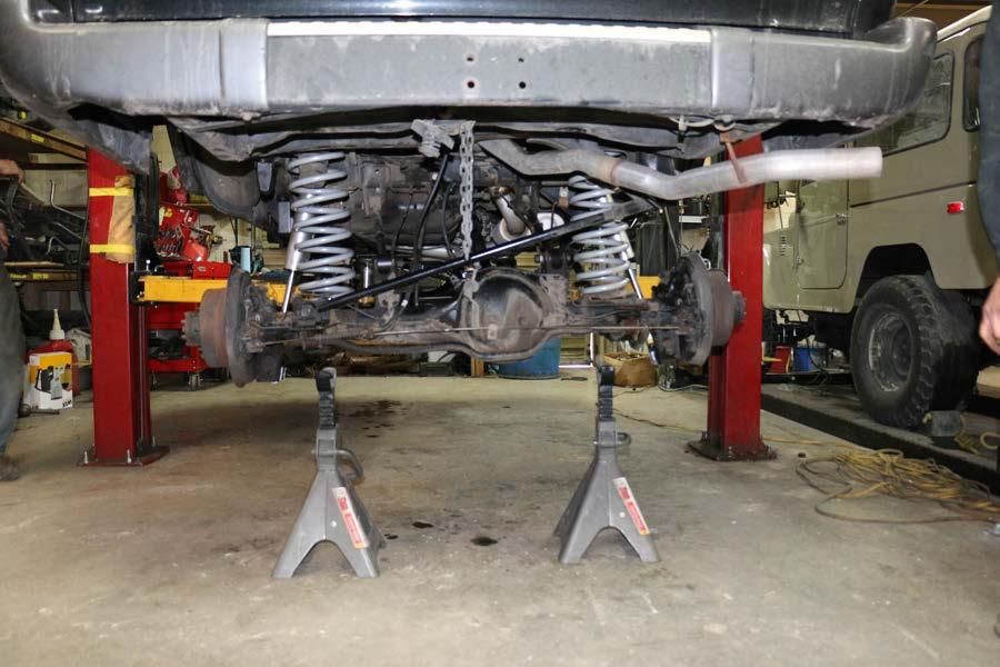
6 Step 1 - The Basics Find a good shop where you have plenty of room to work. If you have access to a lift, that s preferable. If you have to do it on jack stands, you ll need a buddy or two. We recommend using at least a twoton jack stand that can get pretty tall You ll need a good sturdy jack stand as well. Step 2 - Penetrating Oil on Anything to Remove It is not uncommon for bolts to break. We had a lower shock bolt that broke on us on the last install and it took 2 hours to drill the bolt out, bring the pieces out and re-tap the hole. Pre-lubricate everything (and sometimes heating up bolts before you start to turn them) gives you your best shot at not breaking any bolts and making your install quicker and easier. If you do break a bolt, don't panic, take a deep breath, and keep going. Step 3 - Remove Bump Stops and Sway Bar Brackets See FIGURE 1 below To remove the bump stops use a 12mm. Be careful with these bolts, they're known to break. We used a 3/8 impact to remove these and we're lucky...they all came out without breaking. The new bump stops we're installing are 70 series Land Cruiser bump stops. They're about 3/4" longer. You can use the factory bumps with a spacer if you want to, however for the Slinky Kit, you get the new 70 series bump stops. 6
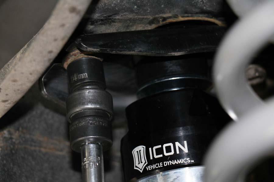
7 To remove the sway bar brackets use a 12mm. To remove the sway bar from the extension end bracket use a 14mm. We used the 3/8 impact on this, as well. If all you have is a box wrench or a socket set, those will work fine, too. The sway bar can just hang for now. Step 4 - Shock Removal See FIGURE 4 Below First remove the lower shock bolt with a 17mm socket. This is another bolt that is known to be corroded so take extra care when removing this bolt. If it brakes, you might just decide to quit now or hire someone with a lot more patience than you. Next remove the upper shock bolts with a 14mm with a long extension. Finally, use a pry bar to pry off the lower shock mount (it was a little sticky) and then could remove the entire shock assembly. From there we placed the shocks on a work bench and removed the top nut (which is a 19mm) and then saved the rear shock top brackets for later use). Step 5 - Rear Brake Line Removal and Installation See FIGURE 2 below Using a 10mm line wrench, remove the rear brake hard line from the soft line. Next remove the brake line bracket from the frame. After that has been removed you can simply turn the soft brake line counterclockwise to spin the soft line from the axle with the bracket in tact. Our new brake line is 5" longer (this comes with the Slinky kit) 7
8 Reassemble with a c clip and the old Toyota clip. Now install the new rear brake line. This should pretty straight forward. Install the axle side first, otherwise you'll end up twisting your brake line to the point where it's useless. Step 6 - Remove Rear Axle Breather Hose This might have already come out on it's own, but using a 12mm remove the bracket. Then replace the old hose with a new, 24" length of 1/4" rubber hose. You can use fuel or vacuum hose or whatever. Take out the breather top vent, bracket an bottom clamp. Reinstall into new hose and then reinstall by connecting via the bracket to the frame. Step 7 - Spring Removal First loosen the rear pan hard rods at axle side using a 24mm. Second, loosen the lower control arms at the axle side, also a 24mm. Just loosen the nut side, not the bolt side. Third, do the upper control arms on the axle side. Loosen those nuts, as well, which are 24mm. When you loosen all these 24mm bolts everything will begin to drop, so be prepared and keep your head out of the way so you don't end up needing to go to the sidelines for a concussion protocol or something. Now you can remove the springs. If you didn't leave yourself enough room doing this on jack stands, you might need to raise the chassis a bit in order for the axle to droop so the springs can come out. You need full droop and about 6" of distance between the bottom of the rotor and the ground in order to remove the springs. To remove the springs simply 8
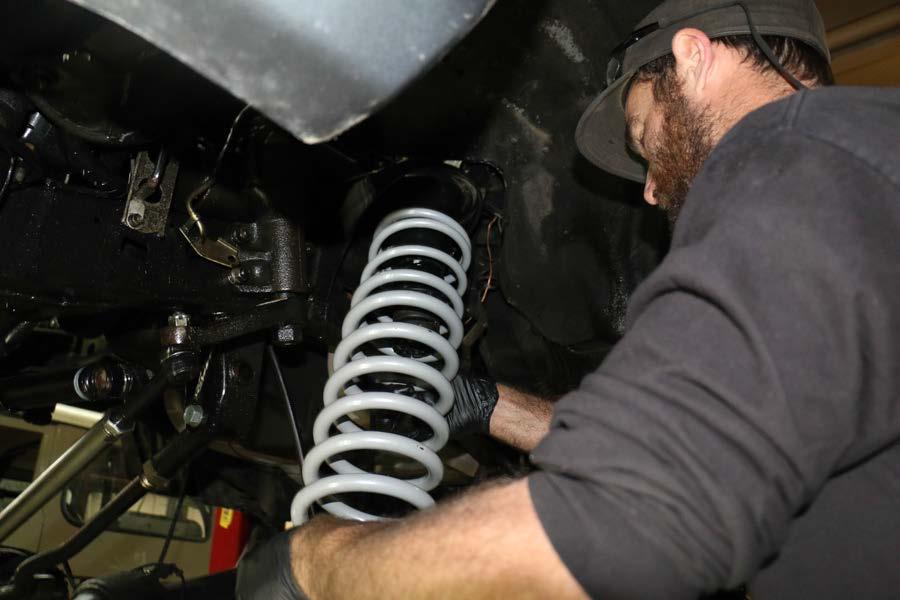
9 pick them up off the lower seat, lean the lower end forward and they should come right out. The Slinky coils provide the perfect blend of on and off road use. I can enjoy a comfy ride on the highway, but at the same time go and hammer a trail and be just as comfortable and in control on the toughest trails. The intermediate coil is designed to carry an additional load capacity of 400 pounds while the heavy can carry 900 additional pounds. The Slinky springs operate on the theory of "pre-load" - the OME springs will carry the load no problem but when they droop when you're on a trail when the axle drops out, the OMEs may unseat from the coil bucket and bang around. The Slinky springs might unseat a bit, too, but they will unseat less than the OMEs. Less unseating results in the coils not banging around as much. I don't want to get too much into suspension theory here, but the long and the short of it is this...slinky coils will make everything from moving around too much and give you a smoother ride. Step 8 - Coil Install To install the coils pay attention to the coil tags because there is a left hand and right hand coil. The coils are labeled with "LH" for left hand and "RH" for right hand. The left handed one goes on the driver side. The right handed one goes on the passenger side. The left handed one is about 1/4" taller to account for the added weight of the gas tank and the driver on the left side. This combats the "Cruiser Lean" that you often see on Land Cruisers. To install make sure the little rubber grommet is in there on the top of the coil. This prevents the coil from making too much noise. Swing the coil up and into place and then swing the bottom of the coil into the coil bucket and ensure the ail of the coil is positioned correctly. It may or may not be necessary to have someone stand on the axle in order to get it to go down so you can get the coils seated. 9
10 Step 9 - Install the Shocks See FIGURES 5,6,7,8,9 and 10 below Woo-ha-ha. Now we get into the fun part. Installing your beautiful, shiny, ride-like-a-bat-out-of-hell-and-stay-in-control Slinky shocks. Prep the lower shock mount by cleaning it up with a wire wheel brush or cup brush. Get all the corrosion and crap off of there so your new shocks mount up nice and clean. Next unpack everything and lay it all out. Identify the top plates for the shock by the stamping "L" for left and "R" for right. The top of the shock goes together like this: Washer, bushing, top plate, bushing, washer, first nut and then the jamb nut. Swing in your shock and then bolt the top plate to the frame leaving them about a 1/4" loose. Then reattach the shock on the lower axle side. Be sure to clean threads on the bolt and the hole on the lower shock bolt. The thread pitch is 12mm x Make sure they're nice and clean so you can apply anti seize to the bolt and outside of the axle shock mount (see photos). The Slinky kit comes with a stone shield that protects the lower shock mount. These will need to be cut (see photo) 2 5/8" off the top before installing them (this prevents the stone shield from damaging your shock when fully compressed). Then bolt them on to about 30 ft. lbs. You may need a second guy to pull down the axle to get the shocks in. You may also need a plastic dead blow hammer to pound in the shock over the axle shock shaft. Now go back and tighten the top two bolts that go into the frame on the top of the shock. (Note this next step is for Stage 4 shocks only). There is a ring clamp holder and a worm clamp that need to be bolted on the 10
11 shock so it holds it against the frame so the CDC valve cannot rotate and get damaged. We didn't have a nice new pair on our hands, so we took advantage of a good used set that we had access to. This next step might be tricky if you're on jack stands because visibility may be limited. You need to tighten the top shock nut and ratchet on the first nut to a point where your jamb nut can go on nice and snug while leaving two threads visible at the end of the shaft. It's preferable to use a gear wrench to do this. CRITICAL: Have a second guy hold the shock on the very top of the shock and the very bottom of the shock and NOT by the reservoir. You will break the reservoir off if you hold the reservoir while trying to tighten everything down. There are no torque specs to consider here...it's all about leaving those two threads visible at the end of the shaft when you're all done. You can use a strap wrench to help hold the shock in place. Boom, on to step 10. Step 10 - Install the Sway Bar Links See FIGURES 3, 12, and 13 below Next install your new bump stops and sway bar drop brackets. Be sure to use anti-seize on your bolts. Your new sway bar links include new extensions, new bushings and washers. These new ones don't leave you a lot of room to install ahead of time. You'll need to install them with weight on the axle in order to compress the bushings, giving you enough space on the extension shaft to get the nut threaded on at the end. Once you've got weight on your axle, use a jack to push up the end of the sway bar into the sway bar bracket so it compresses the bushing so you can get your washer and nut on. Thread the nut so as to leave two threads visible. 11
12 Pretty much every bolt you thread back on, put anti seize on it. It will make it easier for servicing. Now your sway bar is installed. With full weight on your axle, torque down your control arm nuts, pan hard bolts, and all the factory torque specs. Step 11 - Remove Old Front Shocks and Loosen Radius Arm Nuts Remove your old front shocks and then loosen the radius arm nuts...yep. I just said that in my subject heading. Next remove the front sway bar mounts on the frame side. Then remove your brake lines following the same steps you followed removing the rear brake lines. Step 12 - Remove the Radius Arms Using a 22mm and 24mm remove the Radius arms by backing out the nuts and then punching out the bolts with a punch and a hammer as they may be sticky. Step 13 - Remove Cater Bushings (OEM) for New Caster Bushings Install with diagram using a press. Here is a link for a detailed install: Step 14 - Washer Mod / Caster / Plate Mods SEE SEPARATE CASTER CORRECTION LINKS on our website here: 12
13 We want to achieve a total of 4 degrees of caster correction. 2 degrees with the bushings and 2 degrees with the washer mod. (Now this is for 80 series that have not had caster change yet.) You might already have Caster change. Depending on what you have will dictate what you need to do to achieve 4 degrees total. This also depends on the lift size! For a 50mm kit, just the caster bushings or washer mod is desirable for 2 degrees total. For the 75mm lift you will need both for a total of 8ish degrees. End caster that must be achieved on flat ground is degrees! Step 15 - Install Radius Arms Reverse procedure from removal. Torque to specified specs above Step 16 - Install the Front Coils See FIGURES 13B below Step 17- Install Front Shocks See FIGURES 15 and 16 below Put the upper stud mount in first on the frame side, then push down on the axle to allow the lower stud mount to place in the axle side bracket. You may have to have a buddy help you collapse the shock a bit to install it. Bolt down the shocks using the Icon shock instructions in the shock box. Step 18 - Remove and Install Pan Hard Rods Adjust pan hard rods equally from side to side. This requires a 24 mm wrench. 13
14 Measure the distance from the frame to the inside of the tire on both sides. Then remove the frame side of the pan hard and adjust to half of the distance you measured. Reinstall the pan hard and re-measure. Repeat until complete. NOTE: this must be done with the weight of the cruiser on the ground. Torque the bolts to factory specs above. Step 19 Remove & Install Front Brake Lines See FIGURE 14 below Remove the brake lines and reinstall the new brake lines supplied with the kit. Use a 10 and 17mm line wrench so you don t strip the factory metal hard line ends. NOTE: If you have a 1991 to Series, it only used one 4 extended brake line for driver s side, which comes in the kit. You will have a brake line left over in your kit. Step 20 - Bleed Brake System Keep bleeding all calipers and rear prop adjusting valve until hard pedal is achieved. Step 21 - Adjust Drag Link Adjust drag link (front steering rod that attaches to the pitman arm). We like to loosen the rod clamps, remove the stabilizer mount to make this a little easier. Place truck on ground with the full weight and front tires straight. Next, turn the rod and watch the steering wheel. By turning the rod and 14
15 watching the steering wheel, you can keep turning the rod until the wheel becomes straight again! Tighten and remount the bracket! Step 22 - Install Front Sway Bay Drop Brackets Using the supplied front sway bar hardware, install the brackets. Tighten the bolts to 22 ft. lbs. Step 23 Complete! Enjoy the best kit on the market! 15

16 Figures / Images Figure 1 - Bump stops 16

17 Figure 2 - Rear factory brake line to be replaced 17

18 Figure 3 Rear sway bar drop bracket 18


19 Figure 4 Rear upper shock mounting plate Rear upper shock mounting plate to be removed. Right and left specific. 19

20 Figure 5 Shock mount bolt Clean shock mount bolt with a wire wheel 20

21 Figure 6 Stud bolts Keep upper stud bolts loose until plate is mounted. Then tighten upper bolts 21

22 Figure 7 - Tap lower shock mount Tap with 12mm x 1.25 tap 22

23 Figure 8 Install shock 23


24 Figure 9 Lower shock mount rock shields Trim lower stone shields, Take off worth 24


25 Figure 10 Stage 4 shock pin set up Rear stage 4 shock pin locking set up. This is so the CDC valves don t rotate and hit the frame. Use wo rm clamp to lock into place. (Lower pic) 25

26 Figure 11 Install bump stops 26


27 Figure 12 Rear sway bar mount 27
28 Figure 13 Installing rear axle B 28


29 Figure 14 Connect brake line 29


30 Figure 15 Install front coil 30


31 Figure 16 Worm clamp positioning Shock installed with correct rotation and worm clamp (FRONT) 31
OVER THE KNUCKLE 1-TON STEERING INSTALLATION INSTRUCTIONS
 OVER THE KNUCKLE 1-TON STEERING INSTALLATION INSTRUCTIONS TOOLS NEEDED Grinder with cutoff wheel, sawzall, cutting torches, or a plasma cutter Welder (for optional sway bar mounts) Hand drill with a ½
Installation Guide for the TeraFlex Elite LCG JK 4 Long Arm Suspension System
 Tera Manufacturing, Inc. 5251 South Commerce Dr. Murray, Utah 84107 Phone/801.288.2585 Fax/801.713.2313 www.teraflex.biz INSTALLATION GUIDE Installation Guide for the TeraFlex Elite LCG JK 4 Long Arm Suspension
Installation Notes: #86000-R Race Series +3.5 L/T Kit
 159 North Maple St. Unit J, CORONA CA 92880 P. 951-737-9682 F. 951-737-9006 WWW.CHAOSFAB.COM Installation Notes: #86000-R Race Series +3.5 L/T Kit Factory manual is recommended for removal and re-installation
RHINO SUSPENSION SYSTEM INSTALLATION INSTRUCTIONS
 PARTS INCLUDED: 2 FRONT UPPER A-ARMS 2 FRONT LOWER A-ARMS 2 UNI-BALL JOINTS 2 UNI-BALL JOINT STUDS 2 UNI-BALL JOINT CAPS 2 RETAINING RINGS 1 FRONT SHOCK ASSEM. 2 DELRON STEERING STOPS 2 SHOCK MOUNT SPACERS
PPM-8022 / PPM-8042 JEEP JK STAGE 2 SYNERGY SUSPENSION SYSTEM Version 1
 POLY PERFORMANCE MFG. 870 INDUSTRIAL WAY, SAN LUIS OBISPO, CA (805) 242-0397 PPM-8022 / PPM-8042 JEEP JK STAGE 2 SYNERGY SUSPENSION SYSTEM Version 1 GENERAL NOTES: These instructions are also available
PPM-8023 / PPM-8043 JEEP JK SYNERGY STAGE 3 SUSPENSION SYSTEM Version 1
 SYNERGY MFG. 870 INDUSTRIAL WAY, SAN LUIS OBISPO, CA (805) 242-0397 PPM-8023 / PPM-8043 JEEP JK SYNERGY STAGE 3 SUSPENSION SYSTEM Version 1 GENERAL NOTES: These instructions are also available on our website;
INSTALLATION INSTRUCTIONS FOR: RE DOOR JK WRANGLER RE DOOR JK WRANGLER 3.5 STANDARD SUSPENSION SYSTEM
 RUBICON MANUFACTURING INC. 3290 MONIER CIR., RANCHO CORDOVA, CA. 95742 916-473-4600 INSTALLATION INSTRUCTIONS FOR: RE7122 2 DOOR JK WRANGLER RE7142 4 DOOR JK WRANGLER 3.5 STANDARD SUSPENSION SYSTEM Safety
05-07 F /2 SUSPENSION KIT
 92147900 05-07 F250 4 1/2 SUSPENSION KIT Thank you for choosing Rough Country for your suspension needs. Rough Country recommends a certified technician installs this system. In addition to these instructions,
2013+ DODGE RAM " Kit PART# STOP! READ THIS FIRST!
 NOTE: 2013+ DODGE RAM 3500 4" Kit PART# 54346 STOP! READ THIS FIRST! **READ THESE ENTIRE INSTRUCTIONS BEFORE STARTING ANYTHING** or chroming, which can damage the strength and structure of the metal, any
For all Ram x4 Trucks, and all Ram x4 trucks.
 Dodge Off Road, LLC Specializing in Dodge Ram Solid-Axle 4x4 Suspension and Steering for Off Road Applications 855.9009.DOR sales@dodgeoffroad.com dodgeoffroad.com DODGE OFF ROAD 5 th GEN STEERING KIT
Installation Guide for Rough Country 2.5 inch Lift Kit w/o Shocks (07-15 Wrangler JK) Item # J10212
 Item # J10212") Installation Guide for Rough Country 2.5 inch Lift Kit w/o Shocks (07-15 Wrangler JK) Item # J10212 Installation Time: 3 Hours Tools Required: Jack (2 helps, but not needed) Jack stands(2 3-ton, 2 2-ton)
Installation Guide for Rough Country 2.5 inch Lift Kit w/o Shocks (07-15 Wrangler JK) Item # J10212 Installation Time: 3 Hours Tools Required: Jack (2 helps, but not needed) Jack stands(2 3-ton, 2 2-ton)
GM C10 Street Grip
 Part # 11365010/11365110-1973-1987 GM C10 StreetGrip Front Components 11369590 Delrin Control Arm Bushings 11369300 Drop Spindles 11362350/11362351 Front CoilSpring Kit 11369515 Front HQ Series Shocks
How to Change Front Brake Pads on a Toyota Corolla
 How to Change Front Brake Pads on a Toyota Corolla Link to this article on (All other links in this document are disabled) Follow this picture guide to change the front brake pads on a 2003-2008 Toyota
DODGE OFF ROAD T-STYLE STEERING KIT INSTALLATION INSTRUCTIONS
 Dodge Off Road, LLC Specializing in Dodge Ram Solid-Axle 4x4 Suspension and Steering for Off Road Applications 855.9009.DOR sales@dodgeoffroad.com dodgeoffroad.com DODGE OFF ROAD T-STYLE STEERING KIT INSTALLATION
Carli Suspension Front Instructions
 Carli Suspension Front Instructions 94-08 DODGE 2500-3500 4X4 SUSPENSION SYSTEM Note: Prior to installation, carefully inspect the vehicle=s steering and drive train components. Be sure to check ball joints,
2008 Toyota Tundra 4WD Brake Job: A Quick Job and Even Quicker Write-Up.
 FRONT BRAKES: 2008 Toyota Tundra 4WD Brake Job: A Quick Job and Even Quicker Write-Up. 1. Remove this bolt holding brake line bracket to the suspension. 2. I had to replace all 4 rotors at 60K miles, so
Lowering Spring Installation on a Mustang GT
 Lowering Spring Installation on a 99-04 Mustang GT This installation is very the same installation that many of the 79-04 Mustangs excluding Cobra require. Time to install: 2-3 hours to do alone with a
Commander SUSPENSION SYSTEM INSTALLATION INSTRUCTIONS
 PARTS INCLUDED: 2 - FRONT UPPER A-ARMS 2 - FRONT LOWER A-ARMS 4 - COTTER PINS 2-12MM JAM NUTS 2 - TIE ROD EXTENDERS 8- FLANGED DELRON BUSHINGS 4- DELRON CASTER SPACERS 6 - GREASE FITTINGS 3 - BEARING REMOVAL
Installation Instructions for BMR Lowering Springs Performance ( Mustang GT)
") Installation Instructions for BMR Lowering Springs Performance (2015-2017 Mustang GT) Time Required: 3+ hours Notes: This install was done with the performance springs from BMR, but install should be the
Installation Instructions for BMR Lowering Springs Performance (2015-2017 Mustang GT) Time Required: 3+ hours Notes: This install was done with the performance springs from BMR, but install should be the
INSTALLATION INSTRUCTIONS: LONG TRAVEL KIT 07+ FJ CRUISER and 05+ TACOMA
 INSTALLATION INSTRUCTIONS: LONG TRAVEL KIT 07+ FJ CRUISER and 05+ TACOMA ISNTALLATION DIFFICULTY: Advanced APPROX TIME: 6-8 Hours REQUIRED TOOLS: 14mm-35mm sockets, wrenches, and ratchet 9/16 and 5/8 12
AEV30308AA Last Updated: 05/31/18. 4 DUALSPORT sc SUSPENSION system for RAM 1500 air ride standard and rebel INSTALLATION GUIDE
 AEV30308AA Last Updated: 05/31/18 4 DUALSPORT sc SUSPENSION system for RAM 1500 air ride standard and rebel INSTALLATION GUIDE PLEASE READ BEFORE YOU START TO GUARANTEE A QUALITY INSTALLATION, WE RECOMMEND
Installation Guide for the JK Wrangler 4-Inch Suspension System with FlexArms
 INSTALLATION GUIDE Tera Manufacturing, Inc. 5251 South Commerce Dr. Murray, Utah 84107 Phone/801.288.2585 Fax/801.713.2313 www.teraflex.biz Installation Guide for the JK Wrangler 4-Inch Suspension System
BBK Ceramic Long Tube Headers (99-04 Cobra and Mach 1) - Installation Instructions
 - Installation Instructions") BBK Ceramic Long Tube Headers (99-04 Cobra and 03-04 Mach 1) - Installation Instructions The below installation instructions work for the following products: BBK Ceramic Long Tube Headers (99-04 Cobra
BBK Ceramic Long Tube Headers (99-04 Cobra and 03-04 Mach 1) - Installation Instructions The below installation instructions work for the following products: BBK Ceramic Long Tube Headers (99-04 Cobra
05-07 F250 6 SUSPENSION KIT
 92159300 Stabilizer Drop Brackets Track Bar Bracket Control Arm Bracket Brake Line Drop Bracket Sway Bar Link Ext. Hardware Bags Pitman Arm 6111 Add-a-leaf 6578 3 Block and U-Bolt Kit 05-07 F250 6 SUSPENSION
2005-Pres. Ford Mustang Camber Plate Installation Instructions:
 2005-Pres. Ford Mustang Camber Plate Installation Instructions: J&M Products once again outdoes our competitors with these fully adjustable PATENT PENDING Camber & Caster plate assemblies for the 2005-2010
AEV30213AH Last Updated: 04/28/17. jk wrangler dualsport sc suspension INSTALLATION GUIDE
 AEV30213AH Last Updated: 04/28/17 jk wrangler 3.5 4.5 dualsport sc suspension INSTALLATION GUIDE PLEASE READ BEFORE YOU START TO GUARANTEE A QUALITY INSTALLATION, WE RECOMMEND READING THESE INSTRUCTIONS
»Product» Safety Warning
 #F1420 Installation Instructions 2011 Ford Super Duty F250/350 4wd 4" Suspension Lift Read and understand all instructions and warnings prior to installation of product and operation of vehicle. Zone Offroad
FITMENT BACKCOUNTRY 2.0-6" LIFT 6" Systems Require a Drop Pitman Arm, "T" Style Steering & Driveshaft to be lengthened 2"
 PLEASE VISIT: Forums.CarliSuspension.com Troubleshooting advice or to download an electronic copy of this document. FITMENT BACKCOUNTRY 2.0-6" LIFT 6" Systems Require a Drop Pitman Arm, 08.5+ "T" Style
1204AA Ford Mustang Double Adjustable Trailing Arms
 1204AA 79-04 Ford Mustang Double Adjustable Trailing Arms Special Tools Required for this Installation - 4 post lift or alignment rack preferable - Air Chisel, Angle Finder (Digital Preferred), Dead blow
Prerequisites: Shop Manual (recommended) pages 3-9 through 3-13.
 pages 3-9 through 3-13.") Prerequisites: Order your gaskets average about $25.00 bucks X 2 so $50.00 4NK-11193-00-00 Obtain a shim kit (Should have several 265 and 270s) (Some dealers will exchange) Obtain a Valve Bucket Tool YM-33961
Prerequisites: Order your gaskets average about $25.00 bucks X 2 so $50.00 4NK-11193-00-00 Obtain a shim kit (Should have several 265 and 270s) (Some dealers will exchange) Obtain a Valve Bucket Tool YM-33961
AEV30213AF Last Updated: 05/24/18. jk wrangler dualsport sc suspension right hand drive INSTALLATION GUIDE
 AEV30213AF Last Updated: 05/24/18 jk wrangler 3.5 4.5 dualsport sc suspension right hand drive INSTALLATION GUIDE PLEASE READ BEFORE YOU START TO GUARANTEE A QUALITY INSTALLATION, WE RECOMMEND READING
80-96 Ford F150 / Bronco 4WD Class II 4"- 6" Suspension Lift Installation Instructions
 www.skyjacker.com Required Tool List: 80-96 Ford F150 / Bronco 4WD Class II 4"- 6" Suspension Lift Installation Instructions Safety Glasses Metric / Standard Wrenches & Sockets Floor Jack Jack Stands Measuring
08-09 F250 8 SUSPENSION KIT
 92159200 08-09 F250 8 SUSPENSION KIT Thank you for choosing Rough Country for your suspension needs. Rough Country recommends a certified technician installs this system. In addition to these instructions,
2011 F250 6 SUSPENSION KIT
 92156500 Thank you for choosing Rough Country for your suspension needs. 2011 F250 6 SUSPENSION KIT Rough Country recommends a certified technician installs this system. In addition to these instructions,
INSTALLATION INSTRUCTIONS 88511
 INSTALLATION INSTRUCTIONS 88511 For Suspension System RS6511: Ford Super Duty Requires coil spring kit RS80117 or RS80119 for a complete installation READ ALL INSTRUCTIONS THOROUGHLY FROM START TO FINISH
KIT # CSS-C SUSPENSION LIFT KIT
 14385 Veterans Way Moreno Valley, CA 92553 Phone: (951) 571-0212 Fax: (951) 571-0215 2001-2010 CHEVROLET SILVERADO 1500 AND 2500 HD 4WD AND 2WD PICK-UP 1999-2010 CHEVY 2500 4WD PICK-UPS 2001-2010 2500
Suspension System RS6525 (B)
") 88525 Rev A Suspension System RS6525 (B) Requires coil spring kit RS80116 (B) or RS80118 (B) for a complete installation Ford Super Duty READ ALL INSTRUCTIONS THOROUGHLY FROM START TO FINISH BEFORE BEGINNING
88525 Rev A Suspension System RS6525 (B) Requires coil spring kit RS80116 (B) or RS80118 (B) for a complete installation Ford Super Duty READ ALL INSTRUCTIONS THOROUGHLY FROM START TO FINISH BEFORE BEGINNING
INSTALLATION GUIDE. High Steer Kit
 AEV30212AE Last Updated: 12/09/16 High Steer Kit Designed for 2007 current Jeep JK Wrangler and Wrangler Unlimited models in all trim levels, including Rubicon, with at least 3.0 of suspension lift. INSTALLATION
Installation Instructions
 2003-Present Toyota 4Runner 2007-2014 FJ Cruiser LRT 3" Lift Kit by Low Range Off-Road (SKU# LR-LRFJ4RU) Installation Instructions Suggested Tools: CAUTION: Safety glasses should be worn at all times when
RAM LIFT KIT PART# STOP! READ THIS FIRST!
 NOTE: 2014-2016 RAM 2500 4 LIFT KIT PART# 54340 STOP! READ THIS FIRST! **READ THESE ENTIRE INSTRUCTIONS BEFORE STARTING ANYTHING** or chroming, which can damage the strength and structure of the metal,
Steeda Lower Control Arms ( )
") Steeda Lower Control Arms (2005-2012) NOTE: The following installation was performed on a 2007 Mustang GT/California Special. The control arms were previously sold in a blue color, but now they are sold
Steeda Lower Control Arms (2005-2012) NOTE: The following installation was performed on a 2007 Mustang GT/California Special. The control arms were previously sold in a blue color, but now they are sold
PRE-INSTALLATION Ford F150 4WD 4" Suspension Lift Kit
 2009-2013 Ford F150 4WD 4" Suspension Lift Kit PRE-INSTALLATION 25007 2 - Knuckle (Driv/Pass) 2 - Crossmember (Front/Rear) 2 - Differential Bracket (Driv/Pass) 1 - Diff. Brace Bracket (Pass) 2 - Front
INSTALLATION INSTRUCTIONS 88518
 INSTALLATION INSTRUCTIONS 88518 For Rancho Suspension Systems RS6518: 2009 FORD F-150 4WD READ ALL INSTRUCTIONS THOROUGHLY FROM START TO FINISH BEFORE BEGINNING INSTALLATION Rev A IMPORTANT NOTES! WARNING:
Part # Camber Caster Plates Ford Mustang All Ford Mustang GT500
 Part # 24220 Camber Caster Plates 2005-2010 Ford Mustang All 2007-2014 Ford Mustang GT500 J&M Products once again outdoes our competitors with these fully adjustable (Protected under US Patent No. 8,820,759
Part # Chevy Level 3 Street Challenge Package One Piece Frame
 350 S. St. Charles St. Jasper, In. 47546 Ph. 812.482.2932 Fax 812.634.6632 www.ridetech.com Part # 11020399 55-57 Chevy Level 3 Street Challenge Package One Piece Frame Front Components: 1 11013011 TQ
1203AA GM A-BODY Double Adjustable Trailing Arms
 1203AA 64-67 GM A-BODY Double Adjustable Trailing Arms Warning: This installation should be performed by a trained professional. Note, pictures in this booklet are from a 77-96 GM B Body. Installation
Rear Wheel Removal (by BassCliff)
") Rear Wheel Removal (by BassCliff) Hello to my GS riding friends! After picking up a nail in my rear tire (while on the freeway at 75mph!) I thought I would take a few pictures to help illustrate the rear
Rear Wheel Removal (by BassCliff) Hello to my GS riding friends! After picking up a nail in my rear tire (while on the freeway at 75mph!) I thought I would take a few pictures to help illustrate the rear
INSTALLATION INSTRUCTION 88581
 INSTALLATION INSTRUCTION 88581 FOR RANCHO SUSPENSION SYSTEM RS6581B: DODGE RAM READ ALL INSTRUCTIONS THOROUGHLY FROM START TO FINISH BEFORE BEGINNING INSTALLATION Rev C IMPORTANT NOTES! WARNING: This suspension
Installation Instructions
 Preparing your vehicle to install your brake system upgrade 1. Rack the vehicle. 2. If you don t have a rack, then you must take extra safety precautions. 3. Choose a firmly packed and level ground to
2013-UP 3500 Dodge 5 Lift Kit SRW
 92369200 2013-UP 3500 Dodge 5 Lift Kit SRW Thank you for choosing Rough Country Suspension for your Off Road needs. Rough Country recommends a certified technician installs this system. In addition to
Sport S/T3 Suspension Installation Guide
 1 Sport S/T3 Suspension Installation Guide #1258250-JK 2-Door Sport S/T3 (No Shocks) #1258200-JK 2-Door Sport S/T3 (w/ Fox Shocks) #1258450-JK 4-Door Sport S/T3 (No Shocks) #1258400-JK 4-Door Sport S/T3
Team Z Motorsports. K-Member installation instructions
 Team Z Motorsports K-Member installation instructions Parts Included: 1-Tubular K-Member Needed Items-Solid Steering Shaft Offset Steering Rack Bushings Optional-Heavy Duty Bolt Kit Tubular Front Lower
07-13 TOYOTA TUNDRA 2WD 6" LIFT SPINDLES
 MAXTRAC SUSPENSION 4030 E LEAVERTON CT ANAHEIM, CA 92807 714-630-0363 WWW.MAXTRACSUSPENSION.COM SALES@MAXTRACSUSPENSION.COM PRODUCT: K886764 07-13 TOYOTA TUNDRA 2WD 6" LIFT SPINDLES PARTS LIST QTY LIFT
97-06 JEEP TJ/LJ LONG ARM UPGRADE KIT
 921663U00 97-06 JEEP TJ/LJ LONG ARM UPGRADE KIT Thank you for choosing Rough Country for your suspension needs. This kit is an upgrade kit only. This kit includes frame mounting points and adjustable long
INSTALLATION INSTRUCTIONS 89551
 INSTALLATION INSTRUCTIONS 89551 For Rancho Suspension System RS66551B: Ford F250, F350 Super Duty 4x4 DIESEL ONLY (Single Rear Wheels Only With or Without Auxiliary Spring). (WILL NOT WORK ON GAS ENGINES
JK 3 Install Kit Instruction Pack
 JK 3 Install Kit Instruction Pack 1 Contents: Rear Sway Bar Link Instructions Spring Instructions Bumpstop Instructions Rear Track Bar Bracket Instructions Extended Brake Line Instructions Quick Disconnect
Steeda Sport Mustang Lowering Springs (2005+) - Installation Instructions
 - Installation Instructions") Steeda Sport Mustang Lowering Springs (2005+) - Installation Instructions The below installation instructions work for the following products: Steeda Sport Mustang Lowering Springs (2005+) Please read
Steeda Sport Mustang Lowering Springs (2005+) - Installation Instructions The below installation instructions work for the following products: Steeda Sport Mustang Lowering Springs (2005+) Please read
INSTALLATION INSTRUCTION 89400
 INSTALLATION INSTRUCTION 89400 FOR RANCHO SUSPENSION SYSTEM RS66400B: 2012 RAM 1500 4WD. READ ALL INSTRUCTIONS THOROUGHLY FROM START TO FINISH BEFORE BEGINNING INSTALLATION Rev B IMPORTANT NOTES! WARNING:
Part # Chevy Level 2 Air Suspension Package One Piece Frame
 350 S. St. Charles St. Jasper, In. 47546 Ph. 812.482.2932 Fax 812.634.6632 www.ridetech.com Part # 11020299 55-57 Chevy Level 2 Air Suspension Package One Piece Frame Front Components: 1 11013001 Master
Installation Guide for TeraFlex 3-inch Lift for Grand Cherokees (3Z)
") Installation Guide for TeraFlex 3-inch Lift for Grand Cherokees (3Z) Think safety first when installing your new suspension system. Use these instructions to install the TeraFlex 3Z. Information regarding
Installation Guide for TeraFlex 3-inch Lift for Grand Cherokees (3Z) Think safety first when installing your new suspension system. Use these instructions to install the TeraFlex 3Z. Information regarding
09-UP FORD F150 6 LIFT KIT
 92159800 09-UP FORD F150 6 LIFT KIT THANK YOU FOR CHOOSING ROUGH COUNTRY FOR YOUR SUSPENSION NEEDS. Rough Country recommends a certified technician install this system. In addition to these instructions,
STEP #1: Remove the wheels from the truck. There are (6) 21mm lug nuts holding each wheel on... Remember Lefty Loosy, Righty Tighty.
 21mm lug nuts holding each wheel on... Remember Lefty Loosy, Righty Tighty.") - CustomTacos.com Page 1 of 36 How-To: Toytec Lift Install Read all of these install instructions prior to installing Toytec's suspension lift. I cannot be held responsible for any damages or personal
- CustomTacos.com Page 1 of 36 How-To: Toytec Lift Install Read all of these install instructions prior to installing Toytec's suspension lift. I cannot be held responsible for any damages or personal
INSTALLATION INSTRUCTION 88088
 INSTALLATION INSTRUCTION 88088 For Rancho Suspension Systems RS6588 & RS6589: FORD F-150 READ ALL INSTRUCTIONS THOROUGHLY FROM START TO FINISH BEFORE BEGINNING INSTALLATION Rev B IMPORTANT NOTES! WARNING:
INSTALLATION INSTRUCTION Rev A
 INSTALLATION INSTRUCTION 88587 Rev A FOR RANCHO SUSPENSION SYSTEM RS6587B: 2009 DODGE RAM 1500 READ ALL INSTRUCTIONS THOROUGHLY FROM START TO FINISH BEFORE BEGINNING INSTALLATION IMPORTANT NOTES! WARNING:
INSTALLATION INSTRUCTIONS
 88553 Rev A INSTALLATION INSTRUCTIONS For Rancho Suspension System RS66553B: 2017-2011 Ford F250 / F350 Super Duty 4x4 2.5 Leveling Kit (Available in black only. Component in illustrations may be red for
2014+ DODGE RAM LIFT KIT PART# STOP! READ THIS FIRST!
 NOTE: 2014+ DODGE RAM 2500 8 LIFT KIT PART# 54320 STOP! READ THIS FIRST! **READ THESE ENTIRE INSTRUCTIONS BEFORE STARTING ANYTHING** or chroming, which can damage the strength and structure of the metal,
XJ CHEROKEE LIFT KIT
 921633XN200 Thank you for choosing Rough Country for your suspension needs. 84-01 4.5 XJ CHEROKEE LIFT KIT Rough Country recommends a certified technician installs this system. In addition to these instructions,
Anti-Sway Bars Installation Instructions For Mazda MX-5 PART #
 Anti-Sway Bars Installation Instructions For 2006+ Mazda MX-5 PART # 920-330 Tools required: A jack and jack stands, 5mm Allen wrench, ratchet, 10mm, 12mm and 14mm, combination wrenches and sockets, 21mm
*1274BAG9* 1274BAG GM 4-6 SUSPENSION KIT N2.0. Thank you for choosing Rough Country for your suspension needs A
 92127400A 88-98 GM 4-6 SUSPENSION KIT N2.0 Thank you for choosing Rough Country for your suspension needs. *1274BAG9* 1274BAG9 Rough Country recommends a certified technician installs this system. In addition
2011 F SUSPENSION KIT
 92156300 Thank you for choosing Rough Country for your suspension needs. 2011 F250 4.5 SUSPENSION KIT Rough Country recommends a certified technician installs this system. In addition to these instructions,
97-06 JEEP TJ / LJ 2 1/2 LONG ARM KIT W/ PERFORMANCE 2.2 SERIES SHOCK ABSORBERS
 92PERF1628 97-06 JEEP TJ / LJ 2 1/2 LONG ARM KIT W/ PERFORMANCE 2.2 SERIES SHOCK ABSORBERS Thank you for choosing Rough Country for your suspension needs. Rough Country recommends a certified technician
AEV-Nth JK High Steer Kit Installation Instructions
 AEV-Nth JK High Steer Kit Installation Instructions designed for: 2007-current Jeep JK Wrangler and Unlimited models in all trim levels including Rubicon with at least 3.0 of suspension lift. Vehicle Applications
STOP---READ THIS FIRST!
 STOP---READ THIS FIRST! **Read These Entire Instructions Before Starting Anything** 2011-13 FORD F-250 & F350 6 & 8 LIFT KITS 5680 W. Barstow, Fresno, CA 93722 PH: (559) 226-8196 (559) 277-0457 FAX www.mcgaughys.com
NOTE: LIFETIME PRODUCT WARRANTY
 Carli Suspension: 422 Jenks Circle, Corona, CA 92880 Tech Support: (714) 532-2798 CS-F45-D30-05 2005-07 Ford Dominator - 4.5 Lift System CS-F45-D30-08 2008-10 Ford Dominator - 4.5 Lift System CS-F45-D30-11
If you have any difficulties at all, please give us a call. Thank you and enjoy your MetalCloak Products!
 PRODUCT: TJ/LJ 3.5 Dual Rate Lift RockSport Edition READ INSTRUCTIONS IN FULL BEFORE INSTALLATION. QUESTIONS? CALL 916-631-8071 M-F 7:00 AM 5:00 PM PST The MetalCloak experience includes the ease of installation
Tools Needed: Class 8.8 Class MM 55ft/lbs 75ft/lbs 14MM 85ft/lbs 120ft/lbs 16MM 130ft/lbs 165ft/lbs 18MM 170ft/lbs 240ft/lbs
 921788000 JEEP JK 6 LONGARM Rough Country recommends a certified technician install this system. In addition to these instructions, professional knowledge of disassemble/reassembly procedures as well as
BBK LONG TUBE HEADERS (99-04 GT, Mach 1, Bullitt)
") BBK LONG TUBE HEADERS (99-04 GT, Mach 1, Bullitt) Install Time: Approx. 8-10 hrs Parts Needed: BBK Long Tube Headers Shorty mid pipe X/H O2 wiring harness extensions Hi-temp thread locker Tools Required:
BBK LONG TUBE HEADERS (99-04 GT, Mach 1, Bullitt) Install Time: Approx. 8-10 hrs Parts Needed: BBK Long Tube Headers Shorty mid pipe X/H O2 wiring harness extensions Hi-temp thread locker Tools Required:
Slave Cylinder Weep Hole Drilling Procedure
 Slave Cylinder Weep Hole Drilling Procedure Tools Required: T20 Torx Driver T25 Torx Driver T25 Torx Bit with ¼ Ratchet Wrench 4mm Hex Key (Allen wrench) 5mm Hex Key 6mm Hex Key 8mm Hex Key 12mm Hex Key
Ford Super Duty 4 & 6 Suspension Lift Ford Super Duty 8.5" Suspension Lift Installation Instructions
 www.skyjacker.com Required Tool List: 2005-2010 Ford Super Duty 4 & 6 Suspension Lift 2008-2010 Ford Super Duty 8.5" Suspension Lift Installation Instructions * Assorted Drill Bits * Brake Fluid * Metric
60-65 Falcon, Comet & Ranchero Coil Spring IFS
 60-65 Falcon, 62-65 Comet & 62-65 Ranchero Coil Spring IFS All engine installations with this front end will require a rear sump oil pan. 289-302 Small Block Ford Motors Milodon rear sump pan holds 7 quarts
PARTS LIST: 8581 DODGE LONG ARM BRACKETS 03-13
 SYNERGY MFG. 870 INDUSTRIAL WAY, SAN LUIS OBISPO, CA (805) 242-0397 8580 03-12 DODGE 2500/3500 4X4, 06-08 1500 MEGACAB 4X4 LONG ARM SUSPENSION KIT V3.0 GENERAL NOTES: These instructions are also available
INSTALLATION INSTRUCTION 88094
 INSTALLATION INSTRUCTION 88094 FOR RANCHO SUSPENSION SYSTEM RS6594B 4WD & 2WD NISSAN TITAN READ ALL INSTRUCTIONS THOROUGHLY FROM START TO FINISH BEFORE BEGINNING INSTALLATION Rev D IMPORTANT NOTES! WARNING:
TOYOTA FJ CRUISER 6 SUSPENSION KIT
 92177000 TOYOTA FJ CRUISER 6 SUSPENSION KIT Thank you for choosing Rough Country for your suspension needs. Rough Country recommends a certified technician installs this system. In addition to these instructions,
Our goal is to make the install a breeze. Please read the entire guide before beginning.
 www.airkewld.com Page 1 of 6 IRS Axle Kit Install IRS Axle Kit Install Our goal is to make the install a breeze. Please read the entire guide before beginning. KITS SHOULD INCLUDE 2 - Control-arm mounting
»Product» Safety Warning
 #F1422 Installation Instructions 2008-2010 Ford Super Duty F250/350 4wd 4" Radius Arm Suspension Lift Read and understand all instructions and warnings prior to installation of product and operation of
Mirrored from:
 Mirrored from: http://www.wranglerforum.com/f274/install-synergy-suspension-ball-joints-write-up-147062.html 03-18-2012, 02:43 AM #1 SilverSport Supporting Member WF Supporting Member Install Synergy Suspension
2013+ DODGE RAM LIFT KIT PART# STOP! READ THIS FIRST!
 NOTE: 2013+ DODGE RAM 3500 8 LIFT KIT PART# 54324 STOP! READ THIS FIRST! **READ THESE ENTIRE INSTRUCTIONS BEFORE STARTING ANYTHING** or chroming, which can damage the strength and structure of the metal,
6 S-10 Pickup/Jimmy/Blazer Torsion Bar Drop Kit
 92124300 6 S-10 Pickup/Jimmy/Blazer Torsion Bar Drop Kit Thank you for choosing Rough Country for all your suspension needs. Rough Country recommends a certified technician install this system. In addition
»Product» Safety Warning
 #F1424 Installation Instructions 2011 Ford Super Duty F250/350 4wd 4" Radius Arm Suspension Lift Read and understand all instructions and warnings prior to installation of product and operation of vehicle.
PRODUCT USE INFORMATION
 9RC61000 Jeep YJ Body Lift Thank you for choosing Rough Country for all your suspension needs. This body lift fits both manual and Automatic equipped vehicles!!! Refer to last page of this Instruction
Installation Instructions
 79-04 Ford Mustang Perfect Fit K-Member Part # 20022 Installation Instructions Congratulations on your purchase of the AFCO Perfect Fit K-member for the 79-04 Ford Mustang. Please read and understand each
4, 6 Suspension System. Ford F250/350 4WD Part#: ,
 Part#: 013411, 013611 4, 6 Suspension System Ford F250/350 4WD 2005-2007 Rev. 071917 491 W. Garfield Ave., Coldwater, MI 49036. Phone: 517-279-2135 E-mail: tech-bds@sporttruckusainc.com Read And Understand
INSTALLATION GUIDE. 3 Dualsport suspension. ram truck 2500/3500. AEV30243AA Last Updated: 04/10/15
 3 Dualsport suspension AEV30243AA Last Updated: 04/10/15 ram truck 2500/3500 INSTALLATION GUIDE PLEASE READ BEFORE YOU START TO GUARANTEE A QUALITY INSTALLATION, WE RECOMMEND READING THESE INSTRUCTIONS
RAM FRONT RADIUS ARM DROP BRACKETS Installation Instructions
 THE INFORMATION CONTAINED IN THIS DRAWING IS THE SOLE PROPERTY OF SYNERGY MFG. ANY REPRODUCTION IN PART OR WHOLE WITHOUT THE WRITTEN PERMISSION OF SYNERGY MFG IS PROHIBITIED. Revisions Rev. Description
XJ CHEROKEE LIFT KIT
 92169600 84-01 6.5 XJ CHEROKEE LIFT KIT Thank you for choosing Rough Country for your suspension needs. Rough Country recommends a certified technician installs this system. In addition to these instructions,
Installation Instructions
 Instructions Created by an: Revised 7-11-17 LRT 2005-2017 3/1 Leveling/ Lift Kit for Toyota Tacoma by Low Range Off-Road (SKU# LR-LRTACO) Installation Instructions Suggested Tools: CAUTION: Safety glasses
AEV JK Standard Suspensions Installation Instructions
 AEV JK Standard Suspensions Installation Instructions 3.0 and 4.0 suspension systems designed for: 2007-current Jeep JK Wrangler and Unlimited models including Rubicon packages Kit Part Numbers Vehicle
Sport Sway Bar Kit Mustang
 Sport Sway Bar Kit 22102 2005 Mustang Installation of Hotchkis Front Sway Bar 1F Raising Vehicle Securely block the rear wheels of the vehicle. Use a jack to lift up the front of the vehicle and use jack
Suspension System RS6582B
 Suspension System RS6582B Tahoe/Yukon READ ALL INSTRUCTIONS THOROUGHLY FROM START TO FINISH BEFORE BEGINNING INSTALLATION IMPORTANT NOTES! WARNING: This suspension system will enhance the off-road performance
Slingshot Rotrex Supercharger Kit
 Slingshot Rotrex Supercharger Kit This supercharger kit improves on the Slingshot by forcing more dense air into the engine and creating more power. Installation time of the supercharger depends on you