Turf Revitalizer 6-14hp
|
|
|
- Jocelin Sims
- 6 years ago
- Views:
Transcription

1 Turf Revitalizer 6-14hp Owner s Manual
2 CONTENTS Page# Safety Unpacking and Initial setup Controls Operation For Best results Servicing your Turf Revitalizer Storage 16 Troubleshooting..17 Warranty..18 Parts Breakdown
3 Safety Do not start and/or run engine indoors. Engine produces carbon monoxide and can cause severe bodily harm, including death. Read entire owner s manual before operation. Do not refuel engine until engine has cooled off. The exhaust becomes very hot during operation. Never touch the muffler as this will cause severe burns. Never operate unit without all safety guards in place. This includes, but is not limited to the belt, and blade cutter reel covers. Make sure that you and any bystanders are wearing personnel protection equipment. Including eye and hearing protection along with long pants. Do not wear loose fitting clothes or jewelry as this may become caught in rotating parts. (Children should never operate machinery.) Never bypass kill switches. Do not leave unit while engine is running, or while parts are still in motion. Check for buried cables, wires, and irrigation pipes before seeding, dethatching or power raking. Remove all debris from area to be seeded, as debris may become flying projectiles. Use extreme caution on slopes. Wear shoes with an aggressive pattern to reduce chances of slipping and/or falling. Avoid running over manhole covers, concrete, asphalt, rocks, etc while seeding. This may cause damage to the unit. If abnormal vibration occurs discontinue use of machine until service can be performed. Always disconnect sparkplug before servicing
 o Units are shipped with the handle folded in the down position. Handle bolts must be removed to correctly position the handle (see figure1). Secure the handle with all four bolts. Step3.")
4 Unpacking Unpacking and Initial Setup Step1. Cut away crate. o Use a reciprocating saw to cut away wooden crate. Step2. Fold Handles up. (Note: On the 13-14HP units this task takes two people.) o Units are shipped with the handle folded in the down position. Handle bolts must be removed to correctly position the handle (see figure1). Secure the handle with all four bolts. Step3. Remove unit from pallet. o Pull the transmission engagement T-handle out, this puts the unit into neutral/freewheel (see figure 1b). o Pull the unit off of the pallet. This may be difficult as the transmission has not been broken in. Remove Bolt and move to middle hole. Pull Out to manually move unit Figure 1 Figure 1b - 4 -
 o Start the engine.")
5 Initial Setup Step1. Top the engine off with oil. o Units are shipped with some oil. Engine should be topped off with the correct oil viscosity. See engine manual for the correct oil viscosity. Step2. Adjust the transmission cable. (Note: On the 13-14HP units the blade engagement cable will need to be installed at handle; See page 13 for proper adjustment procedures.) o Start the engine. If the transmission is creeping in the Park" position (see figure 2) adjust the cable. Moving the cable down will stop forward creep. Moving the cable up will prevent reverse creep. NOTE: Adjusting nuts for transmission. Figure 2 The transmission and cutter belt will stretch during the first 5 hours of use. They must be adjusted to prevent the belts from slipping, causing premature belt wear. See page for the correct procedure on adjusting the belts

6 Controls Cutter Blades ON / OFF Seed Flow ON / OFF Pistol Grip Transmission Control Note: Seed Flow the seed flow is turned on/off with the seed flow control. The unit is designed so seed flow slows or almost stops completely when the front wheels are off the ground while making turns. There is no need to turn the seed flow on & off for each turn. Once the front wheels start turning, the seed flow will instandly go back to the calibrated seed rate
.")


7 Pistol Grip Control- the unit is operated (forward and backward) using a pistol grip control, like those found on a commercial walk behind mower. Disengage the lever, with your thumb, from the park position and release slowly to move forward (Note: 9-14 HP units have two forward cruising speeds). To stop, squeeze the control half way. To go backward, squeeze the control fully. See figure 4. Figure 4. Transmission engagement T-handle- This must be inserted into the frame for the transmission to operate. If you want to manually push the unit, pull the t-handle out of the frame and down to lock into neutral/freewheel. See figure 5. Figure 5. Depth Control Lever The Depth Control Lever is used to raise and lower the blades. This allows a maximum range of blade heights. Pull on the spring plunger knob to release the lever and then lower and raise the blades to the desired position. See figure 6. Do not force handle from side to side, it is made to move forward and backwards only. Figure
see figure 7.")

 The handle needs to be held down when starting the engine and must continue to be held during")
8 Seed Meter Gauge The Seed Meter Gauge is used to adjust the seed flow to a set flow rate. It is calibrated so that you receive the correct amount of seed at any cruising speed. (i.e. the seed flow is proportional to the ground speed)see figure 7. Figure 7. Operator Kill Switch (Lanyard type) The Operator Kill Switch is to be used at all times when the engine is running. Place the lanyard around your wrist or connect securely to your clothing. If the operator should lose control of the machine, the lanyard will be released from the kill switch stopping the unit. See figure 8. Figure 8. Operator Kill Switch (Operator handle kill switch type) The handle needs to be held down when starting the engine and must continue to be held during operation. If the operator should lose control of the machine, release your hand from this switch and the engine will stop running. See figure 9. Figure
9 Before each day of use. Operation o Check engine oil level and air filter. o Check for loose or damaged parts. o Clean dirt and debris from seed gate by turning seed flow setting (seed meter gauge) to #10, then turn the seed flow on. Then go to the front of the unit and move the seed gate back and forth 4-5 times to remove any dirt and debris. NOTE: The seed gate is designed to clean itself when it is allowed to move through the full range of motion. Operation See figure 3 on next page. 1. Set the seed flow to the recommended seed rate. 2. Move the depth control lever to the recommended height. 3. Attach the lanyard to operator. If not equipped with a lanyard, hold down the operator s presence handle. 4. Make sure that the pistol grip control is in the parked position. 5. Turn on/off switch on engine to on. 6. Turn fuel on. 7. If engine is cold turn choke on. If engine is warm leave choke off. 8. Start the engine and turn off the choke. 9. Move the transmission engagement T handle into the frame if it is pulled out. 10. Tilt back on the unit and turn the cutter reel on. Slowly lower the unit to the ground. 11. Turn seed flow on. 12. Move pistol grip control into desired direction of travel


10 13. After use be sure to set the engine switch to off, shut off fuel, and return the blades to the highest position. Figure 3. For Best Results The Turf Revitalizer is a 3 in 1 machine that will power seed, dethatch, and power rake. Power Seeding When over seeding, set the blades to cut slits in the soil ¼ ½ deep. For basic over seeding, only 1 pass is required. If there are a few bare areas due to fungus or dog urine, seed the entire property with one pass, on the bad areas, go forward then backward and forward again to
11 add extra seed. This method will save time and seed while giving a nicer finished product. Dethacthing Because of the Turf Revitalizer s aggressive blade design, you can use the same machine for dethaching. Simply turn off the seed flow and do a single or double pass as desired. It is recommended to dethatch even a newly seeded lawn the following spring or fall to allow the grass to thicken properly which reduces the chance of fungus. Power Raking / Renovation The Turf Revitalizer is the most compact yet powerful power rake on the market. For breaking new ground, leveling, or renovating a lawn, drop the blades down to 1-1 ½ deep. Use the hydrostatic drive to do the work for you. Go forward and backward with the machine to till the ground in very uneven areas, or simply make a double pass in two directions to break up and level the ground in moderate areas. Hard, dry ground works the best. The unit is much more aggressive when breaking up hard dry ground while going backward because the blades are reverses tilling the soil. Multiple passes may be needed if the ground is too soft and engine bogs down. In which case make a couple of shallow passes then increase the cutting depth. Note: The Turf Revitalizer will seed at the same rate going forward and backwards. Note: If there is excessive thatch, it may be necessary to remove the thatch prior to seeding. This will prevent the new grass from suffocating under the thatch. Note: With the Turf Revitalizer, it is very easy to put more grass seed down then is recommended because of the thinking that more is better. Grass that is too thick is very susceptible to fungus during summer months. Seed at the recommended seed rate, most seed rates can be located on the seed bag, or can be obtained from your supplier. Note: Unit performs best when ground is dry
12 Servicing your Turf Revitalizer The Turf Revitalizer is designed to be relatively maintenance free. For long life and to reduce down time some routine service should be performed. Note: Always disconnect the sparkplug before servicing. After each day of use: Units should be tipped forward. Let the seed hopper rest on a piece of wood i.e. 2x4. Note: For the 13-14HP units it takes two people to tip unit forward. Check the underside for excessive build up of dirt. Scrape excessive build up off with a PLASTIC putty knife. PRESSURE WASHING WILL CAUSE EXCESSIVE RUST! This will shorten the life of the bearing. Check for rope, plastic netting, wire etc. that is wrapped around the cutting shaft and remove the foreign material. Look at blades and check for damage. Hold shaft and move in and out to check for excessive movement. If there is excessive movement have unit serviced. Check belts for wear and proper tension. Flip unit back over and check the air filter and engine oil level. After Five hours of usage: Adjust the belt tension! If this step is skipped premature belt failure will occur. If belt failure occurs the cutter belt can be replaced by a standard off the shelf belt found at most auto parts stores when needed. However we recommend using the appropriate replacement belt from your local dealer. NOTE: The drive belt to the transmission is a specially designed belt that must come from your dealer. OFF THE SHELF BELTS WILL NOT WORK!


13 o Procedure for adjusting cutter reel belt tension. 1. Remove the belt cover. 2. Turn on Cutter Reel. 3. With the engine off and the blades in the up position, press forward on the belt tensioner. The belt should be tight and the cutter cable should be slightly loose. Loosen Adjusting nuts here. 4. Turn the blades to the off position, and the tensioner should deflect the belt ass shown causing the belt to release from the drive pulley allowing the blades to free wheel. 5. Note: It is normal for the cutter reel to spin when disengaged for the first 5 hrs of operation or until belt is broken-in (stretches). 6. Replace belt cover


14 o Procedure for adjusting transmission belt tension. 1. Remove the belt cover. 2. Loosen all four nuts shown in figure Slide idler bracket away from engine to increase tension. If movement cannot be obtained insert four c-washers in between the idler bracket and the frame, see figure Retighten all four nuts and replace belt cover. Figure 11. Slide c-washer between plate and frame on all four bolts. Figure
15 Change engine oil at the recommend intervals. Refer to your engine manual for these intervals and correct viscosities. There is no maintenance to the hydrostatic drive system. It is designed to be completely sealed to prevent contamination. The blades are designed to be unbreakable. When replacing worn blades, it is also recommended to change the cutter bearings while they are off the unit as preventative maintenance. o Procedure on replacing blades and bearings. 1. Units should be tipped forward. Let the seed hopper rest on a piece of wood i.e. 2x4. Note: For the 13-14HP units it takes two people to tip unit forward. 2. Remove the belt cover and cutter belt. 3. Lower the blades to allow easier access to bolts. 4. Remove cutter reel. 5. Note: If removing blades only it is not necessary to remove pulley or bearing from the drive pulley side. Loosen the jam nut enough to remove tension from the external snap on the opposite end of the shaft. 6. Replace blades and spacers. Note: Be sure to stagger blades as they are put on. 7. Note: if doing annual service, it is recommended to replace the cutter reel bearings at this time. 8. Note: Also make sure that thread lock is used on all set screws and the jamb nut. Also use anti-seize on all bearings and pulleys (any metal to metal surface) as you slide them on the shaft. See figure Reinstall in unit and check for smooth operation. 10. Adjust cutter belt if needed

16 Antiseize shaft! TL, Set Screws TL Figure 13. TL -Thread Lock. Seed gate cable adjustment. 1. Set seed flow to off position. 2. Check for any gaps in between the seed gate and frame. 3. Make any needed adjustments to the seed gate cable if needed. Do not adjust the cable where there is excessive tension placed on the cable due to pulling the seed gate past the limit of travel. Storage Storage and Troubleshooting Follow the after each use section on page 12. Drip a couple of drops of oil down each cable to prevent rust from forming on the cables. Drain fuel from engine and carburetor bowl, or add a fuel stabilizer
17 Troubleshooting Problem Possible Cause Correction Engine will not start. Engine shutting off on hills or when turning. Engine is stalling. Transmission won t engage. Out of gas. Low Oil. Kill switch. Engine is low on oil. Oil switch is detecting low oil. Blades are set to deep in the ground or ground is too wet. Transmission T-handle not inserted into frame. Fill gas. Top off oil. Hold down OP handle or attach lanyard. Top engine off with oil. Remove orange wire from the front off the engine if hill is excessive (> 30 deg.) Set blades to a higher setting or wait for ground to dry. Insert T-handle, see page 7. Unit lacks power going up hills. Seed hopper gate will not open. Excessive vibration Transmission belt is slipping due to belt stretch. Dirt is building up between the seed gate and frame. Broken blade. Worn bearing. Follow adjusting procedure on page 14. See page 9, for cleaning procedure. Replace all blades. Replace both bearings
18 Warranty Limited Warranty for Turf Revitalizer (6hp and 14hp models) The product carries a 2-year limited warranty from the date of purchase for the original purchaser. Lawn Solutions will replace for the original purchaser free of charge any part or parts found to be defective in material or workmanship. Lawn Solutions may require the defective parts to be returned for further examination. Due to the ease of maintenance on the product, this is a parts only warranty. This is a limited warranty and does not cover damage from abuse to include failure to transport the product correctly. The warrant does not cover standard service items like belts, blades, bushings and bearings. On 3 rd party items like an engine and transmission, Lawn Solutions may provide replacement parts, but it will be up to the OEM to refund any warranty work or part costs. Lawn Solutions will overnight parts if requested and at the cost of the requester, otherwise Lawn Solutions will pay standard shipping charges except for 3 rd party items (engine and transmission)

19 Control Panel ASM


20 Front Parts View Side Parts View

21 Top Parts View
22 - 22 -

23 9-hp Reel ASM

24 6-hp Reel ASM
25 Part Number Item Descriptions Parts Not Shown in Diagrams LS Belt - Transmission (6-hp) TR2060 LS Belt - Transmission (9-hp) TR2090 & TR2085 LS0040b 40b Belt Transmission TR24 LS0040c 40c Belt Transmission TR30 LS Belt - Cutter Blades (6-hp) TR2060 LS Belt - Cutter Blades (9-hp) TR2090 & TR2085 LS0042b 42b Belt Cutter Blades TR24 & TR30 LS LS LS OP Handle Kill Switch ASM (For use with models that use a Red Plastic OP Handle) OP Kill Switch - terminal connector only (For use with models that use a Red Plastic OP Handle) OP Kill Switch - Switch only (For use with models that use a Red Plastic OP Handle) If unit has Red Metal OP Handle use LS0157. LS Lanyard Kill Switch LS Lanyard LS Scotchlok Moisture Resitant Splice LS Ring Terminal 22-18ga wire w/ 5/16" Stud LS Butt Splice 22018ga wire LS Small Black Wire Ties LS Decal Set - Turf Revitalizer LS0038B 38B Decal Seed Flow Graph - TR LS Toe Guard - 6hp LS Toe Guard - 9hp LS Hopper Cover Latch LS Sendec Hr Meter LS Seed Hopper Cover 20"
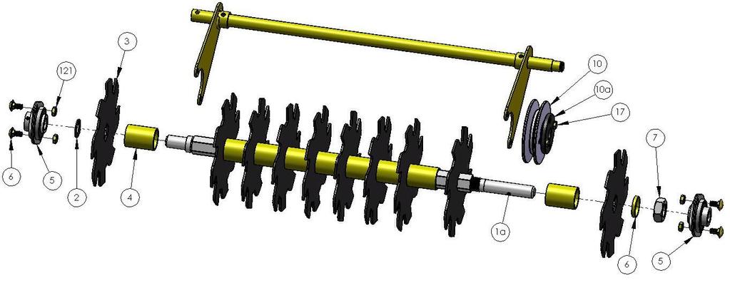
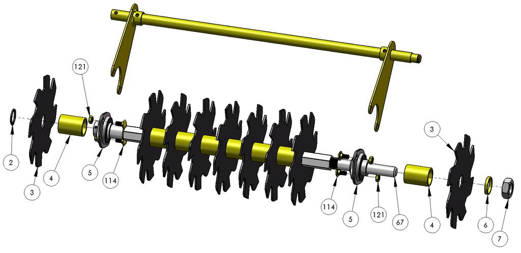
26 Service Parts List Part Number Item Descriptions LS Cutter Shaft 18" Fits Model (TR2060xxx1) LS0001a LS0001b LS0001c 1a Cutter Shaft 20" Fits Model (TR2090xxx1) 1b Cutter Shaft 24 Fits Model (TR2414xxx1) 1c Cutter Shaft 30 Fits Model (TR3014xxx1) LS Retaining Ring - 1" Heavy Duty LS Cutter Blade (.120") LS Cutter Spacer (1 3/8" x 1.825) LS0005a 5a 3/4" Bearing NOTE: (Carrier bearing for transmission on TR24 and TR30) Cutter Shaft Bearing is LS0005 LS /4" Shielded Bearing (Cutter Shaft Bearing on all models) LS Cutter Spacer (1 3/8" x 0.200) LS Nut - 7/8-14 Jam LS Washer Flat ( ) LS E-Clip - 3/4" LS Pulley - 4" Cast LS0010a 10a Pulley - Split Taper Bushing (3/4" Bore) LS Key Stock 3/16" x 3/16" x 1.25" (undersized) LS hp Cutter Reel ASM (Does not include Pivot ASM shown on pg 23; shown for reference only) LS0012a 12a 6-hp Cutter Reel ASM (Does not include Pivot ASM shown on pg 24; shown for reference only) LS0012b 12b 24 Cutter Reel ASM (Fits Model TR2414xxx1) LS0012c 12c 30 Cutter Reel ASM (Fits Model TR3014xxx1) LS0013 LS Nut - 1/4-20 Locking 14 Nylon Spacers 1/2" Long LS Ball Knob 1/4" - 20 LS Control Pivot Lever LS Carriage Bolt 1/4-20 x 3/4"
27 LS0018 LS0019 LS0020 LS0021 LS0022 LS0023 LS0024 LS0025 LS0026 LS0027 LS0028 LS0029 LS0030 LS Control Base Brkt 19 Bolt - 1/4-20 x 2" Hex Head 20 Neutral Lock (6hp) 21 Neutral Lock (9hp-14hp) 22 Rubber Grip - 1" Bar 23 Nylon Spacer 3/8" Long 24 Nylon Washer (White).062 thick 25 Handle - Aluminum Cast 26 Bolt - 3/8-16 x 1-1/2" Hex Head 27 Cable - Transmission 28 Button Head Cap Screw 5mm-.8 x 55mm 29 Lock Nut - 5mm Cable - Seed Flow 31 Cable - Cutter LS Washer - 1/4" LS Trans Cable Brkt (Handle) LS Handle ASM TR20xxxxA1-TR20xxxxB1 (Some earlier TR20xxxxC1 have this handle) LS0034a 34a Folding Handle ASM for TR20xxxxC1-TR20xxxxD1 LS0034b 34b Handle ASM for TR24 LS0034c 34c Handle ASM for TR30 LS OP Handle Kill Switch ASM (For use with models that use a Red Plastic OP Handle) LS0036 LS0037 LS Lanyard Kill Switch 37 Lanyard 38 Decal Set - Turf Revitalizer LS0038B 38B Decal Seed Flow Graph - TR LS0039 LS Belt - Transmission (6-hp) 40 Belt - Transmission (9-hp) LS0040b 40b Belt Transmission TR
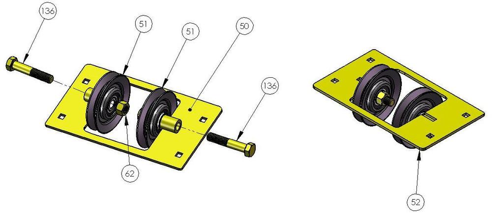
28 LS0040c 40c Belt Transmission TR30 LS0041 LS Belt - Cutter Blades (6-hp) 42 Belt - Cutter Blades (9-hp) LS0042a 42a Belt Cutter Blades TR24 & TR30 LS Transmission LS0043b 43b Transmission TR24 LS0043c 43c Transmission TR30 LS0044 LS Tire 4.10 / (6hp) 45 Tire 11/ (9hp) LS0045a 45a Tire and Wheel ASM 13 TR24 & TR30 LS0046 LS0047 LS Pulley - 6hp Engine 47 Pulley - 9hp 14hp Engine 48 Cable - Trans Neutral Valve LS T-Knob 1/4" - 20 LS0050 LS0051 LS0052 LS0053 LS0054 LS0055 LS0056 LS0057 LS0058 LS0059 LS Trans Idler Brkt 51 Pulley - Trans Idler 52 Complete Trans Idler ASM 53 Idler Arm ASM 54 Arm ASM (Cutter Cable) 55 Pulley - V-Idler w/.625 Bore 56 Bushing Bronze 57 Spring Torsion Coils 58 Bushing Support Bracket 59 Bolt - 1/4-20 x 1-3/8" Hex Head 60 5/16" Shoulder Bolt (1/4-20 head) LS Spacer 1" x 0.75 LS0062 LS0063 LS Nut - 3/8-16 Locking 63 Engine HP 64 Engine HP
29 LS Engine HP LS Carriage Bolt 5/16-18 x 5/8" LS Frame ASM - TR20" LS Handle Extensions - TR20xxxxA1-TR20xxxxB1 (Some earlier TR20xxxxC1 have this handle) (Flat Steel) LS0070a 70a Folding Handle Extensions TR20xxxxC1-TR20xxxxD1 (Round Tube) LS Seed Gate TR20 LS0071b 71b 24 Seed Gate TR24 LS0071c 71c 30 Seed Gate TR30 LS Mixer TR20 See Note Below. LS0072b 72b 24 Mixer TR24 LS0072c 72c 30 Mixer TR30 Note LS0073 LS0072 is Hex and Fits LS0073; Units Equipped with a round Axle must order both parts Axle Hex Front Shaft TR20 LS0073b 73b 24 Axle Hex Front Shaft TR24 LS0073c 73c 30 Axle Hex Front Shaft TR30 LS0074 LS0075 LS0076 LS Depth Bracket Inner (w/ holes) 75 Depth Bracket Outer 76 Bearing Holder (47mm Flange) Cutter Pivot Shaft TR20 LS0077b 77b 24 Cutter Pivot Shaft TR24 LS0077c 77c 30 Cutter Pivot Shaft TR30 LS Bearing Fork TR20 LS0078b 78b Bearing Fork TR24 & TR30 LS Depth Control Arm TR20 LS0079b 79b Depth Control Arm TR24 & TR30 LS0080 LS0081 LS Cable Bracket (Seed Gate Front) 81 Cable Bracket (Cutter on Frame) 82 Trans Cable Brkt (Bottom)
30 LS Finger Guard TR20 LS0083b 83b Finger Guard TR24 & TR30 LS Spacer 5/8" x LS Spacer 5/8" x 2.25 LS0086 LS Seed Flow Dial 88 Trans Mount Bracket LS0088a 88a Transmission Mount Frame Side TR24 & TR30 LS0088b 88b Transmission Mount Center TR24 & TR30 LS0089 LS Idler Arm Support Bracket (Bottom) 90 Belt Cover - 9hp LS0090b 90b Belt Cover TR24 & TR30 LS Belt Cover - 6hp LS Spacer 1" x 1.47 LS Spacer 1" x 2.54 LS Washer Flat ( ) LS Spring Extension (#96) LS0097 LS Toe Guard - 6hp 98 Toe Guard - 9hp LS0098b 98b Toe Guard TR24 & TR30 LS0099 LS0101 LS Plunger ASM 101 Pulley - Flat Idler 102 Pulley - V-Idler LS Washer Lock 5/16" LS0104 LS0105 LS0107 XREF /16" - 20 Rivet Nut 105 Adhesive Cord (wire) clip 107 Spring Pin 1/4" x 1-1/4" (Order LS0312) 3/8 x 2 Spring Pin If your unit is equipped with ¼ pins drill out to 3/8 an install. LS E-Clip - 5/8" LS Button Head Cap Screw 1/4-20 x 1/2"
31 LS Spring Pin 1/4" x 1" Steel LS Cable Clip 1/4" LS Carriage Bolt 1/4-20 x 1 1/4"" LS Carriage Bolt 1/4-20 x 1" LS Carriage Bolt 5/16-18 x 3/4" LS Carriage Bot 5/16-18 x 1" LS Button Head Cap Screw 1/4-20 x 1" LS0119 LS0120 LS0121 LS0122 LS0125 LS0126 LS0127 LS Nut - 3/8-16 Jam Locking 120 Nut - #10-24 Locking 121 Nut - 5/16-18 Locking 122 Nut - 1/4-20 Jam Locking 125 Scotchlok Moisture Resitant Splice 126 Ring Terminal 22-18ga wire w/ 5/16" Stud 127 Butt Splice 22018ga wire 128 Small Black Wire Ties LS Button Head Cap Screw #10-24 x 3/4" LS Button Head Cap Screw 1/4-20 x 3/4" LS0131 LS0132 LS0133 LS0134 LS0135 LS Bolt - 1/4-20 x 1" Hex Head 132 Bolt - 5/16-18 x 3/4" Hex Head 133 Bolt - 5/16-18 x 1-1/2" Hex Head 134 Bolt - 5/16-18 x 2-1/2" Hex Head 135 Bolt - 5/16-18 x 3" Hex Head 136 Bolt - 3/8-16 x 2" Hex Head LS Washer - #10 (3/16") LS Washer - 5/16" LS0140 LS0141 LS OP Kill Switch Rubber Boot (For use with models that use a Red Plastic OP Handle) OP Kill Switch Handle Clamp (For use with models that use a Red Plastic OP Handle) 142 OP Kill Switch - Clamp Screw (For use with models that use a Red Plastic
32 OP Handle) LS0143 LS0144 LS0148 LS0149 LS0150 LS0151 LS0152 LS OP Kill Switch connector (For use with models that use a Red Plastic OP Handle) OP Kill Switch - Switch only (For use with models that use a Red Plastic OP Handle) 148 Hopper Cover Latch 149 Trans Torq Bracket 150 Sendec Hr Meter 151 Spacer x x (Seed Gate) 152 Bolt - 1/4-20 x 3/4" Hex Head 153 Cable Support Bracket LS Seed Hopper Cover 20" LS0156 LS0156a LS0157 LS0160 OP Red Metal Handle (For use with units that have Red Metal OP Handle) OP Linkage (For use with units that have Red Metal OP Handle) OP Switch Gray (For use with units that have Red Metal OP Handle) OP Spring Yellow Zinc (For use with units that have Red Metal OP Handle)
Turf Revitalizer 6-14hp
 Turf Revitalizer 6-14hp Owner s Manual CONTENTS Page# Safety.....3 Unpacking and Initial setup... 4-5 Controls.. 6-8 Operation..9-10 For Best results...10-11 Servicing your Turf Revitalizer.12-16 Storage
Operator's Manual Hydro Walk-behind Aerator
 Operator's Manual Hydro Walk-behind Aerator Models: TA2106BS TA2106HO TA2106SU Lawn Solutions Commercial Products, Inc. TABLE OF CONTENTS READ THIS MANUAL... 3 INTRODUCTION... 3 PRODUCT INFORMATION...
TA2816KA Owner s Manual. Ride-on Aerator. Models Available TA2816KA. Page 1. Lawn Solutions Commercial Products, Inc
 Ride-on Aerator Models Available TA2816KA Page 1 TABLE OF CONTENTS Contents READ THIS MANUAL... 3 INTRODUCTION... 3 PRODUCT INFORMATION... 3 TRAINING & SAFETY... 4 ENGINE SAFETY... 4 OPERATION... 5 MAINTENANCE...
Table of Contents. Safety symbols... 3 Assembly 6. Operation Maintenance Troubleshooting 11. Storage. 12. Notes. 13
 Table of Contents Safety symbols... 3 Assembly 6 Operation... 8 Maintenance... 10 Troubleshooting 11 Storage. 12 Notes. 13 2 Safety Information Attention; this machine can be dangerous! All operators should
Adjustments manual for: Gear Drive, ETS Gear Drive, Walk Hydro, ETS Walk Hydro, Mini Rider, Large Rider Gen 2
 For Husqvarna Parts Call 66-678-96 or 66-56-98 Adjustments manual for: Gear Drive, ETS Gear Drive, Walk Hydro, ETS Walk Hydro, Mini Rider, Large Rider Gen MANUAL NO. 5957 REV. (//) For Husqvarna Parts
57 ROUGH CUT OWNER S MANUAL. With Assembly Instructions For Model: MR55H KUNZ ENGINEERING, INC. / MENDOTA, IL / PH (815) /07
 /07") 57 ROUGH CUT OWNER S MANUAL With Assembly Instructions For Model: MR55H KUNZ ENGINEERING, INC. / MENDOTA, IL 61342 / PH (815) 539-6954 1/07 ASSEMBLY INSTRUCTIONS Read the complete assembly instructions
57 ROUGH CUT OWNER S MANUAL With Assembly Instructions For Model: MR55H KUNZ ENGINEERING, INC. / MENDOTA, IL 61342 / PH (815) 539-6954 1/07 ASSEMBLY INSTRUCTIONS Read the complete assembly instructions
GRASS CATCHER PART S & OPERATORS MANUAL
 GRASS CATCHER PART S & OPERATORS MANUAL WORLDLAWN POWER EQUIPMENT, INC. WORLDLAWN.COM 2415 ASHLAND AVE BEATRICE, NE 68310 800-267-4255 FAX 402-223-4103 2 3 4 OPERATORS MANUAL This catcher manual is for
DIAMONDBACK/EDGE GRASS COLLECTION SYSTEM PARTS & OPERATORS MANUAL
 DIAMONDBACK/EDGE GRASS COLLECTION SYSTEM PARTS & OPERATORS MANUAL GRASS CATCHER W/WEIGHT: TUBE KIT: BLOWER KIT: 48 5101305 632093 632078 52 5101305 542119 632074 60 632086 542120 632081 3 WORLDLAWN POWER
KING COBRA/CALIBER GRASS COLLECTION SYSTEM PARTS & OPERATORS MANUAL
 KING COBRA/CALIBER GRASS COLLECTION SYSTEM PARTS & OPERATORS MANUAL GRASS CATCHER W/WEIGHTS: TUBE KITS: BLOWER KITS: 52 542128 52 542119 5101002 60 542129 60 542120 5101003 2 WORLDLAWN POWER EQUIPMENT
57 ROUGH CUT OWNER S MANUAL. With Assembly Instructions For Models: MR55T, MR55B & MR55K
 57 ROUGH CUT MR55K MR55B OWNER S MANUAL With Assembly Instructions For Models: MR55T, MR55B & MR55K KUNZ ENGINEERING, INC. / MENDOTA, IL 61342 / PH (815) 539-6954 1/05 ASSEMBLY INSTRUCTIONS Read the complete
57 ROUGH CUT WITH ELECTRIC CLUTCH BLADE ENGAGEMENT OWNER S MANUAL. With Assembly Instructions For Model: MR55KE
 57 ROUGH CUT WITH ELECTRIC CLUTCH BLADE ENGAGEMENT OWNER S MANUAL With Assembly Instructions For Model: MR55KE KUNZ ENGINEERING, INC. / MENDOTA, IL 61342 / PH (815) 539-6954 01/05 ASSEMBLY INSTRUCTIONS
57 ROUGH CUT OWNER S MANUAL. With Assembly Instructions. For Models: MR55T, MR55B-17.5HP, MR55B-22HP & MR55K
 57 ROUGH CUT MR55K MR55B OWNER S MANUAL With Assembly Instructions For Models: MR55T, MR55B-17.5HP, MR55B-22HP & MR55K KUNZ ENGINEERING, INC. / MENDOTA, IL 61342 / PH (815) 539-6954 1/07 ASSEMBLY INSTRUCTIONS
Worldlawn Power Equipment, Inc. Industrial Park 2415 Ashland Ave. Beatrice, NE Toll Free Number:
 Operator s Manual R WYZ48/52/60CS BAGGER Worldlawn Power Equipment, Inc. Industrial Park 2415 Ashland Ave. Beatrice, NE 68310 Toll Free Number: 1-800-267-4255 OPERATOR S MANUAL This catcher manual is for
Wheel Horse. 42 Mower. for Lawn and Garden Tractors. Model No & Up. Operator s Manual
 FORM NO. 9 559 Rev A Wheel Horse 4 Mower for Lawn and Garden Tractors Model No. 78 890000 & Up Operator s Manual IMPORTANT: Read this manual carefully. It contains information about your safety and the
THE GIANT-VAC GIANT THATCHER MODELS 55GT 55GTH 91GT
 THE GIANT-VAC GIANT THATCHER MODELS 55GT 55GTH 91GT ASSEMBLY GUIDE AND OPERATOR S MANUAL As you unpack your Giant-Thatcher power unit, you will find the following parts: 1 - Power unit with motor, thatcher
Not for Reproduction. BILLY GOAT AERATOR Owner's Manual AE401, AE401H, AE401H5T Replacement Parts. AE Owner s Manual TINE ROW KIT TINE KIT P/N
 BILLY GOAT AERATOR Owner's Manual AE401, AE401H, AE401H5T Replacement Parts TINE ROW KIT Complete tine row set for replacement of one complete row of tines. Includes mounting plates, spacer, and all hardware.
ProLine. 36 Mower. for Mid-Size Traction Unit. Model No & Up. Operator s Manual
 FORM NO. 8 77 Rev A ProLine 6 Mower for Mid-Size Traction Unit Model No. 05 79000 & Up Operator s Manual IMPORTANT: Read this manual carefully. It contains information about your safety and the safety
ASSEMBLY INSTRUCTIONS
 ASSEMBLY INSTRUCTIONS Read the complete assembly instructions before starting the assembly. You should have: - one mower deck assembly - two carrier arm assemblies - two rear tire assemblies - one ATV
44 and 52 Twin Bagger 100 Series Z Master
 Form No. 7 87 and 5 Twin Bagger 00 Series Z Master Model No. 7855 Serial No. 000000 and Up Operator s Manual English (CE) Contents Page Introduction................................ Safety.....................................
Wheel Horse. 52 Mowers. Model No & Up Model No & Up. Operator s Manual
 FORM NO. 9-567 Wheel Horse 5 Mowers for Lawn & Garden Tractors Model No. 7880 890000 & Up Model No. 7885 890000 & Up Operator s Manual IMPORTANT: Read this manual carefully. It contains information about
Wheel Horse. 48 Mower. for Lawn and Garden Tractors. Model No & Up. Operator s Manual
 FORM NO. 5 Wheel Horse 48 Mower for Lawn and Garden Tractors Model No. 786 990000 & Up Operator s Manual IMPORTANT: Read this manual carefully. It contains information about your safety and the safety
STOP. Broadcast Spreader. Operator's Manual. Model No Safety Assembly Operation Maintenance Parts
 Operator's Manual STOP Broadcast Spreader Model No. 486.2400 DO NOT RETURN TO STORE For Missing Parts or Assembly Questions Call 1-866-56-8388 CAUTION: Before using this product, read this manual and follow
Z Master. 62 Mower. for Z Master Z 255 Traction Unit. Model No & UP. Operator s Manual
 FORM NO. 9 88 Z Master 6 Mower for Z Master Z 55 Traction Unit Model No. 7408 89000 & UP Operator s Manual IMPORTANT: Read this manual carefully. It contains information about your safety and the safety
GROUNDSMASTER. 52 Recycler. for 120 Traction Unit. Model No & UP. Operator s Manual
 FORM NO. 8-980 Rev A GROUNDSMASTER 5 Recycler for 0 Traction Unit Model No. 077 79000 & UP Operator s Manual IMPORTANT: Read this manual carefully. It contains information about your safety and the safety
ProLine. 44 Mower. for 120 Traction Unit. Model No & Up. Operator s Manual
 FORM NO. 9 ProLine Mower for 0 Traction Unit Model No. 05 99000 & Up Operator s Manual IMPORTANT: Read this manual carefully. It contains information about your safety and the safety of others. Also become
Model 858-RH. Operating and Assembly Manual. Palmor Products Inc Serum Plant Road Thorntown, IN 46071
 Model 5-RH Operating and Assembly Manual Palmor Products Inc. 55 Serum Plant Road Thorntown, IN 6071 3/31/015 SAFETY RULES Remember, any power equipment can cause injury if operated improperly or if the
THE GIANT-VAC PTO BLOWER MODELS 2000*/3200**/4000***
 THE GIANT-VAC PTO BLOWER MODELS 2000*/3200**/4000*** Congratulations! ASSEMBLY INSTRUCTIONS AND OPERATOR S MANUAL You have just purchased one of the finest pieces of outdoor power equipment on the market
48 Side Discharge Mower
 FORM NO. 9 7GB Wheel Horse 48 Side Discharge Mower for Lawn & Garden Tractors Model No. 7868 790000 & Up Operator s Manual IMPORTANT: Read this manual carefully. It contains information about your safety
Quiet Collector. Model No & Up
 FORM NO. -8GB Rev A Quiet Collector Model No. 795-890000 & Up Operator s Manual IMPORTANT: Read this manual, and your tractor manual, carefully. They contain information about your safety and the safety
Operating and Assembly Manual
 Model 470-/H/PRO/IC Operating and Assembly Manual Midwest Equipment Manufacturing, Inc. 5225 Serum Plant Road Thorntown, IN 46071 11-11-11 SAFETY RULES Remember, any power equipment can cause injury if
48 Side Discharge Mower
 FORM NO. 9 650 Rev A Wheel Horse 8 Side Discharge Mower for Classic Garden Tractor Model No. 786 890000 & Up Operator s Manual IMPORTANT: Read this manual carefully. It contains information about your
Champion Chippers OPERATOR S MANUAL. Operation & Safety. Includes Model: CX850 CX851. Part #
 OPERATOR S MANUAL Champion Chippers Operation & Safety Includes Model: CX850 CX851 Part # 990026 YOU MUST FILL OUT YOUR WARRANTY REGISTRATION TO ACTIVATE YOUR WARRANTY AND TO QUALIFY FOR PARTS SERVICE!!
North Dakota State University Grounds Maintenance Equipment
 North Dakota State University Grounds Maintenance Equipment I. Introduction Grounds maintenance equipment is an important part of the work activities on NDSU campus. They can make grounds maintenance jobs
ASSEMBLY INSTRUCTIONS FOR CHARGER AND THE BOSS QUICK ATTACH GRASS BAGGER
 ASSEMBLY INSTRUCTIONS FOR CHARGER AND THE BOSS QUICK ATTACH GRASS BAGGER \ \ \ \ ~\ P P-12102 (7/2005) TABLE OF CONTENTS SECTION PAGE WARNING 1 BLOWER PULLEY INSTALLATION 2 ENGINE GUARD REMOVAL BOSS 3
36 Rear Discharge Mower
 FORM NO. 8 95 Rev. A Wheel Horse 6 Rear Discharge Mower for Classic Garden Tractor Model No. 7805 790000 & Up Operator s Manual IMPORTANT: Read this manual carefully. It contains information about your
WOOD CHIPPER WC1105 5PQ (8/08/2012)
") O P E R A T O R ' S M A N U A L WOOD CHIPPER WC1105 5PQ990102 (8/08/2012) To the Owner; Thank-You for choosing a quality product from Frontier Equipment. We strive to give you the best equipment and the
O P E R A T O R ' S M A N U A L WOOD CHIPPER WC1105 5PQ990102 (8/08/2012) To the Owner; Thank-You for choosing a quality product from Frontier Equipment. We strive to give you the best equipment and the
CALIFORNIA TRIMMER MOWER MAINTENANCE MANUAL
 CALIFORNIA TRIMMER MOWER MAINTENANCE MANUAL 2 Table of Contents Section 1: General Information Page Handle Assembly Instructions 4 Maintenance All Models 6 Oil Change Procedures All Models 9 Height Adjustment
DFS Vac Collection System 400 Series Z Master
 Form No. 0 DFS Vac Collection System 00 Series Z Master Model No. 780 Serial No. 000000 and Up Operator s Manual Register your product at www.toro.com Original Instructions (EN/GB) Contents Page Introduction................................
Grooming Reel Kit Greensmaster 3150 and 3250 D
 Grooming Reel Kit Greensmaster 50 and 50 D Model No. 040 Model No. 04 Form No. 5 00 Rev. A Installation Instructions Note: The Grooming Reel Kit can be installed on cutting unit models 040 and 04. Note:
Operator's Manual. VC-60 & VC-60 Plus Harper Industries, Inc. 7/03 Part No
 Operator's Manual VC-60 & VC-60 Plus 2003 Harper Industries, Inc. 7/03 Part No. 970066 Thank you for purchasing a Harper/Goossen Verti-Cutter. As with all Harper/Goossen products, the Harper/Goossen Verti-Cutter
Wheel Horse. 44 Snowthrower. for 5xi Lawn and Garden Tractors. Model No & Up. Operator s Manual
 FORM NO. 8 Rev A Wheel Horse Snowthrower for 5xi Lawn and Garden Tractors Model No. 7966 890050 & Up Operator s Manual IMPORTANT: Read this manual, and your tractor manual, carefully. They contain information
Quiet Collector. Model No & Up
 FORM NO. -0 Quiet Collector Model No. 79-990000 & Up Operator s Manual IMPORTANT: Read this manual, and your tractor manual, carefully. They contain information about your safety and the safety of others.
TECHNICAL DATA BROCHURE ZTR 308/3II
 Date 8/84 Page 1 of 6 TECHNICAL DATA BROCHURE ZTR 308/3II IMPORTANT - READ OPERATOR'S MANUAL BEFORE OPERATION OR MAKING ADJUSTMENTS. ' Seat Adjustment Loosen bolts on sliding brackets under each side of
The information in this operator s manual is limited in application to the Honda mulching kit for Honda H4000 Series lawn tractors with 42 and 46
 The information in this operator s manual is limited in application to the Honda mulching kit for Honda H4000 Series lawn tractors with 42 and 46 mower decks. Before installing or operating this equipment,
THE FINISHING TOUCH 42 FINISH CUT MOWER SELF PROPELLED WALK BEHIND
 Visit us at: www.swisherinc.com OWNER S MANUAL STARTING SERIAL #: L105-074001 MODEL NO. WB11542F Rev. Important! Read and follow all Safety Rules and Instructions before operating this equipment. THE FINISHING
Mid-Size ProLine, Pistol Grip, Gear Drive 15 HP with 36in Side Discharge Mower
 Form Number Mid-Size ProLine, Pistol Grip, Gear Drive 15 HP with 36in Side Discharge Mower Model No. 30529-250000001 and up. Parts Catalog Ordering Replacement Parts To order replacement parts, please
TECHNICAL DATA BROCHURE ZTR 426
 TECHNICAL DATA BROCHURE ZTR 426 Date 8/84 IMPORTANT - READ OPERATOR'S MANUAL BEFORE OPERATION. Page 1 of 6 Seat Adjustment Loosen bolts on sliding bracket under each side of seat, slide seat forward or
Wheel Horse. 48 Mower. for 5xi Tractors. Model No & Up. Operator s Manual
 FORM NO. 9 Wheel Horse 48 Mower for 5xi Tractors Model No. 786 990000 & Up Operator s Manual IMPORTANT: Read this manual, and your tractor manual, carefully. They contain information about your safety
BILLY GOAT AERATOR Owner's Manual AE401, AE401H, AE401H5T Replacement Parts
 BILLY GOAT AERATOR Owner's Manual AE401, AE401H, AE401H5T Replacement Parts TINE ROW KIT TINE KIT Complete tine row set for replacement of one complete row of tines. Includes mounting plates, spacer, and
365L (2001) Page 1 of 36 54" Deck Assembly
 Page 1 of 36 54 Deck Assembly") 365L (2001) Page 1 of 36 54" Deck Assembly 365L (2001) Page 2 of 36 54" Deck Assembly 1 720-0241 1 S Wing Nut Knob 2 703-2817 1 Belt Cover LH 3 703-2816 1 Belt Cover RH 4 747-3306 1 Idler Spring Mounting
365L (2001) Page 1 of 36 54" Deck Assembly 365L (2001) Page 2 of 36 54" Deck Assembly 1 720-0241 1 S Wing Nut Knob 2 703-2817 1 Belt Cover LH 3 703-2816 1 Belt Cover RH 4 747-3306 1 Idler Spring Mounting
THE MODEL 916/918 HYDRAULIC REAR TINE TILLER
 THE MODEL 916/918 HYDRAULIC REAR TINE TILLER CONGRATULATIONS! You are now the proud owner of the BARRETO Model 916/918 tiller. Please take a moment of your time to look over the following information.
Thank you for purchasing a Nelson RainTrain2.
 Thank you for purchasing a Nelson RainTrain2. Read this manual carefully to learn how to operate and service your machine properly. Failure to do so can result in personal injury and/or property damage.
Models: Operator s Manual KIKW36150 KIKW48150 KIKW48170 MANUAL REV. IR (02/16/04)
") Operator s Manual Models: KIKW36150 KIKW48150 KIKW48170 MANUAL 110567 REV. IR (02/16/04) Thank you for buying a YAZOO/KEES! Before operating your new mower, read, understand and follow the important safety
Operator s Manual Models: KIKW36150 KIKW48150 KIKW48170 MANUAL 110567 REV. IR (02/16/04) Thank you for buying a YAZOO/KEES! Before operating your new mower, read, understand and follow the important safety
25 Horsepower Hydrostatic Zero-Turn Commercial Riding Mower
 MMZ 2, 260 2 Horsepower Hydrostatic Zero-Turn Commercial Riding Mower ILLUSTRATED PARTS LIST " Float Cutter Deck - Figure 1 3 1 27 32 17 6 1 11 31 36 3 19 7 23 1 33 38 18 37 22 3 20 2 10 2 12 21 30 39
CR POWER RAKE Owner s Manual
 Accessories SLICING REEL A complete vertislicing reel for your CR. 20" wide reel for use in grasses that require vertical cutting, and for assisting in lawn overseeding projects. P/N 350252 COMPACT POWER
42 Mower Wheel Horse Classic Garden Tractor Attachment
 Form No. 6 9 Mower Wheel Horse Classic Garden Tractor Attachment Model No. 78 000000 and Up Operator s Manual Domestic English (EN) Contents Page Introduction................................ Slope Chart..............................
Wheel Horse. 36 Tiller. Model No & Up. Operator s Manual
 FORM NO. 8 9 Rev. A Wheel Horse 6 Tiller for Classic Garden Tractors Model No. 7970 690000 & Up Operator s Manual IMPORTANT: Read this manual carefully. It contains information about your safety and the
Safety Instructions, Installation & Operator s Manual For
 Safety Instructions, Installation & Operator s Manual For #6-3173 TWIN BAG GRASS CATCHER KIT FOR 38 YARD CRUISERS SERIES 2 MODEL YZ145382BVE IMPORTANT! THIS KIT NOT INTENDED FOR USE ON ANY SERIES OF HZ/HZS
Parts Manual Rev. B RZT48 /
 115 91 36-2 Rev. B Parts Manual RZT48 / 96 62001-00 Please read the operator manual carefully and make sure you understand the instructions before using the machine. Gasoline containing a maximum of 10%
48 Mower Wheel Horse Classic Garden Tractor Attachment
 Form No. 6 96 Rev B 8 Mower Wheel Horse Classic Garden Tractor Attachment Model No. 786 000000 and Up Operator s Manual Domestic English (EN) Contents Page Introduction.................................
36 Tiller Wheel Horse Lawn and Garden Tractor Attachment
 Form No. 9 6 Rev B 6 Tiller Wheel Horse Lawn and Garden Tractor Attachment Model No. 797 890000 and Up Operator s Manual English(En) Contents Page Introduction................................ Safety.....................................
Hydrostatic Zero-Turn Commercial Riding Mower
 Hydrostatic Zero-Turn Commercial Riding Mower Professional Turf Equipment 0" Fabricated Deck ILLUSTRATED PARTS LIST TABLE OF CONTENTS Frame Assembly.................................. 3 0" Fabricated Cutter
STOP 42" HIGH SPEED LAWNSWEEPER. Owner's Manual. Model No's Safety Assembly Operation Maintenance Parts
 Owner's Manual STOP 42" HIGH SPEED LAWNSWEEPER Model No's. 486.242223 DO NOT RETURN TO STORE For Missing Parts or Assembly Questions Call 1-866-576-8388 CAUTION: Before using this product, read this manual
Model 900 Walk Behind Edger
 Little Wonder Model 900 Walk Behind Edger OPERATOR S MANUAL Manual Includes: Safety Information Operating Instructions Maintenance Schedule Tips For Better Operation Illustrated Parts Breakdown Please
Hydrostatic Zero-Turn Commercial Riding Mower
 Hydrostatic Zero-Turn Commercial Riding Mower Professional Turf Equipment 54" Fabricated Deck ILLUSTRATED PARTS LIST TABLE OF CONTENTS Frame Assembly.................................. 3 54" Fabricated
WOOD CHIPPER WC1103 5PQ (8/02/12)
") O P E R A T O R ' S M A N U A L WOOD CHIPPER WC1103 5PQ990101 (8/02/12) To the Owner; Thank-You for choosing a quality product from Frontier Equipment. We strive to give you the best equipment and the
O P E R A T O R ' S M A N U A L WOOD CHIPPER WC1103 5PQ990101 (8/02/12) To the Owner; Thank-You for choosing a quality product from Frontier Equipment. We strive to give you the best equipment and the
PLUGR AERATOR MANUAL including:
 by PLUGR is a registered trademark of SourceOne Inc., a subsidiary of IMSCORP, Lincoln, NE. 603 L Street Lincoln, NE 68508 (888) 418-9065 Fax (402) 474-6604 Web Site: www.plugr.com Email: plugr sales@sourceonex.com
Owner's Manual Instructions for Operation, Maintenance
 Owner's Manual Instructions for Operation, Maintenance Compact Stump and Root Grinder 2961090 (200-6H) Your Dosko grinder is intended for outdoor-use only and can be used to remove many tree stumps and
Parts Manual for PRO GEAR EXPRESS MID-SIZE WALK BEHIND MOWERS SERIES 0 & 1 POWER UNIT MODEL SPE1250KW SPE140KW SPE150KH SPE151KW SPEL150KH
 Parts Manual for PRO GEAR EXPRESS MID-SIZE WALK BEHIND MOWERS SERIES 0 & 1 POWER UNIT MODEL SPE10KW SPE0KW SPE10KH SPE11KW SPEL10KH MOWER UNIT MODEL SPE30 SPE480 SPE31 SPE481 IT IS POLICY OF SNAPPER TO
Operation Manual. 10 Mini-Cultivator MODEL #
 10 Mini-Cultivator MODEL # 103350 Operation Manual This safety alert symbol identifies important safety messages in this manual. Failure to follow this important safety information may result in serious
HIGH RISE POWER ANGLE KIT
 HIGH RISE POWER ANGLE KIT P/N 33-0100 OWNER S MANUAL Application HIGH RISE PUSH TUBE 33-0000 & 34-0000 ATTENTION DEALER: CUSTOMER MUST RECEIVE A COPY OF THIS MANUAL AT THE TIME OF SALE. Before you begin,
ILLUSTRATED PARTS BOOK 4-Cycle High-Wheel 160cc Field Trimmer SWFT16022E
 ILLUSTRATED PARTS BOOK 4-Cycle High-Wheel 160cc Field Trimmer SWFT16022E MAT Engine Technologies, LLC, REV. 20160629 MAT Engine Technologies, LLC, REV. 20160629-1 - Table of Contents Top Level Assembly...
DEBRIS BLOWER 3600 OPERATOR S MANUAL. Debris Blower
 DEBRIS BLOWER 3600 OPERATOR S MANUAL 9-208 Thank you for purchasing a Harper. As with all Harper products, the has been developed through tough design and testing procedures to produce a top quality machine.
Operating and Assembly Manual
 Model 1080 Operating and Assembly Manual Midwest Equipment Manufacturing, Inc. 5225 Serum Plant Road Thorntown, IN 46071 08-02-16 SAFETY RULES Remember, any power equipment can cause injury if operated
Parts Manual Rev. A RZT48 /
 115 91 36-2 Rev. A Parts Manual RZT48 / 96 62001-00 Please read the operator manual carefully and make sure you understand the instructions before using the machine. Gasoline containing a maximum of 10%
TUFF TORQ TRANSAXLE. Tuff Torq Hydrostatic Transaxle. Transaxle Removal Tuff Torq
 Tuff Torq Hydrostatic Transaxle Internal Service 3. Disconnect the cotter pin and the washer to the brake rod (Figure 63). Internal service information is contained in the Tuff Torq KGIA Transaxle Service
TECHNICAL DATA BROCHURE - ZTR 424 & 427 DATE 8/85 PAGE 1 OF 8
 TECHNICAL DATA BROCHURE - ZTR 424 & 427 DATE 8/85 PAGE 1 OF 8 IMPORTANT - READ OPERATOR'S MANUAL BEFORE OPERATION OR MAKING ADJUSTMENTS Deluxe Seat Adjustment Easy hand lever action allows forward and
Grooming Reel Kit Greensmaster Flex 21
 Grooming Reel Kit Greensmaster Flex Part No. 07 800 Form No. 58 68 Rev. A Installation Instructions Setup Instructions Loose Parts Description 007 by The Toro Company 8 Lyndale Avenue South Bloomington,
Collection System. Please read the operator s manual carefully and make sure you understand the instructions before using the machine.
 Collection System 967004601 Please read the operator s manual carefully and make sure you understand the instructions before using the machine. 2012 All rights reserved. Swainsboro, GA. Printed in U.S.A.
Instruction Sheet. Kit Numbers: , , & CRANK PULLEY KIT DISASSEMBLY. Package Contents
 Instruction Sheet Kit Numbers: 5600, 5700, 5800 & 5300 CRANK PULLEY KIT WARNING: FAILURE TO FOLLOW INSTRUCTIONS could result in personal injury and/or damage to unit. Read, understand, and follow all safety
Decals. IMPORTANT INFORMATION Xxxx xxx xxxx xx xxxx x xxxx. WARNING! Xxxx xxx xxxx xx xxxx x xxxx.
 symbols and decals Xxxx xxx xxxx xx xxxx x xxxx. IMPORTANT INFORMATION Xxxx xxx xxxx xx xxxx x xxxx. Used in this publication to notify the reader of a risk of personal injury, particularly if the reader
Chrysler A-Body Tubular A-Arms Installation Instructions A-ARM INSTALLATION
 1967-1976 Dodge Demon 1112 67-72 Chrysler A-Body Tubular A-Arms Installation Instructions Thank you for your purchase of this Hotchkis Performance product. Your A-Arm set was designed with the performance
Parts Manual Rev. A RZT54 /
 115 93 37-27 Rev. A Parts Manual RZT54 / 967 672101-00 Please read the operator manual carefully and make sure you understand the instructions before using the machine. Gasoline containing a maximum of
BAD BOY GRASS BAGGING SYSTEM
 BAD BOY GRASS BAGGING SYSTEM TABLE OF CONTENTS WILL FIT ALL 2019 OUTLAW SERIES MOWERS SAFETY RULES AND INFORMATION.. 2 GENERAL OPERATION.... 3 WARRANTY INFORMATION.... 5 INSTALLATION INSTRUCTIONS.. 6 PAGE
IPL ILLUSTRATED PARTS MANUAL. Model SWZT Walk-Behind. with a serial number of K to K Part No Printed 12/13 Printed in USA
 IPL 0 0 ILLUSTRATED PARTS MANUAL Model SWZT Walk-Behind This manual contains the illustrated parts list for MODELS: SWZT-fs with a serial number of J0000 to J SWZT-fs with a serial number of J0000 to J
Grooming Reel Kit Greensmaster 1000
 Grooming Reel Kit Greensmaster 1000 Model No. 04125 Form No. 3315 139 Operator s Manual Loose Parts Chart DESCRIPTION QTY. USE Frame Assembly R.H. 1 Attaches to right frame Frame Assembly L.H. 1 Attaches
Series 1000 and Cutout
 17.15.Remove the belt from the tractor. NOTE: There were a small number of tractors made using a CVT drive and a 2-speed (L-H-N-R) GT transaxle. The belt must pass over the center mounted gear selector
INSTALLATION INSTRUCTIONS COUPLING NUT MOUNTED CHAIN UNIT KIT. Dealer Customer Vehicle Truck # P.O. # Unit # Bracket # Chain Wheel Kit#
 INSTALLATION INSTRUCTIONS COUPLING NUT MOUNTED CHAIN UNIT KIT Dealer Customer Vehicle Truck # P.O. # Unit # -6350 Bracket # Chain Wheel Kit# 2 Parts List for Unit 995 S 1950 W Ste. B, Springville, UT 84663-800-633-0699
Owners Manual MODEL 45 REEL MOWER MODELS & 45148
 Owners Manual MODEL 45 REEL MOWER TM MODELS 45048 & 45148 TM Rover Mowers Limited Model 45 FOREWORD Thank you for buying a Rover Mower. This manual covers the operation and maintenance of the Rover Model
42 Rear Discharge Mower, 42, 48, and 52 Side Discharge Mower Wheel Horse XT Series Garden Tractor Attachment
 Form No. 8 08 Rev A Rear Discharge Mower,, 8, and Side Discharge Mower Wheel Horse XT Series Garden Tractor Attachment Model No. 789 000000 and Up Model No. 789 000000 and Up Model No. 7890 000000 and
HANDLEBAR AND CONSOLE ASSEMBLY
 Section 6 Parts List HANDLEBAR AND CONSOLE ASSEMBLY 4 33 47 4 49 7 3 78 4 97 46 44 37 38 37 48 39 35 36 34 7 3 4 5 45 4 3 4 0 33 9 96 80 6 300 84 9 5 30 4 9 30 4 3 43 97 0 43 3 68 9 9 Models 753B, F753B
ILLUSTRATED PARTS BOOK. 4-Cycle High-Wheel Field Trimmer UT
 ILLUSTRATED PARTS BOOK 4-Cycle High-Wheel Field Trimmer UT13144 1 Table of Contents Top Level Assembly... 3 Engine Top Level Assembly... 5 Handle Assembly... 7 Frame Assembly... 9 Cutting Head Assembly...
Parts Manual PZ Please read the operator manual carefully and make sure you understand the instructions before using the machine.
 Parts Manual PZ 60 967 045601-00 Please read the operator manual carefully and make sure you understand the instructions before using the machine. When you need spare parts or support in service questions,
O:\Manuals\ MANUAL\ Slicer Seeder P.W doc - 1 -
 O:\Manuals\355. 2000 MANUAL\355...2000 Slicer Seeder P.W. 10.16.2009.doc - 1 - TABLE OF CONTENTS MODEL 355/2000 SLICER SEEDER COVER & TABLE OF CONTENTS....Pages 1 2 STATEMENT OF FACT.... Page 3 SPECIFICATIONS
Model 560 Model 580. Operating and Assembly Manual. Midwest Equipment Mfg Serum Plant Road Thorntown, IN 46071
 Model 560 Model 580 Operating and Assembly Manual Midwest Equipment Mfg. 5225 Serum Plant Road Thorntown, IN 46071 10/14/2018 SAFETY RULES Remember, any power equipment can cause injury if operated improperly
HUSQVARNA ROTARY LAWN MOWER - - MODEL NUMBER (PRODUCT NUMBER 6021P) REPAIR PARTS
 REPAIR PARTS") HUSQVARNA ROTARY LAWN MOWER - - MODEL NUMBER 917.510 (PRODUCT NUMBER 6021P) 1 2 3 59 23 6 43 42 6 13 12 11 14 7 40 50 4 14 5 76 77 75 47 67 15 21 1 46 41 47 65 32 25 52 22 19 39 49 61 REPAIR PARTS 10 39
HUSQVARNA ROTARY LAWN MOWER - - MODEL NUMBER 917.510 (PRODUCT NUMBER 6021P) 1 2 3 59 23 6 43 42 6 13 12 11 14 7 40 50 4 14 5 76 77 75 47 67 15 21 1 46 41 47 65 32 25 52 22 19 39 49 61 REPAIR PARTS 10 39
Tooling Assistance Center
 Safeguards are designed into this application equipment to protect operators and maintenance personnel from most hazards during equipment operation. However, certain safety precautions must be taken by
NOTE: Skids and all hardware for the skids are located in the plow blade box.
 Description Item Qty. Part# 0 0 ATV PUSH TUBE AND BLADE MOUNTING INSTRUCTIONS P/N: 0-0 CUSTOMER MUST RECEIVE A COPY OF THIS INSTRUCTION SHEET AT THE TIME OF SALE NOTE: Skids and all hardware for the skids
Wood Chipper Model C550M Operator's Manual
 Wood Chipper Model C550M Operator's Manual THIS MANUAL MUST BE READ AND UNDERSTOOD BEFORE ANYONE OPERATES THIS MACHINE! Manual# 990023 Revised 01/2010 YOU MUST FILL OUT YOUR WARRANTY REGISTRATION TO ACTIVATE
Maintenance and Repair
 Maintenance and Repair WARNING ALWAYS shut off the engine, remove key from ignition, make sure the engine is cool, and disconnect the spark plug and positive battery terminal from the battery before cleaning,