INSTALLATION INSTRUCTION Wall Mount Mini Split Systems 09 to 60K Btu/h Single, Dual, Triple, Quad-Zone Cooling and Heat Pump W or W/O Heater
|
|
|
- Lee Chambers
- 6 years ago
- Views:
Transcription


1 YMGI, A COMFORT MAKER, A JOY COMPANION, A SATISFACTION GUARANTOR... INSTALLATION INSTRUCTION Wall Munt Mini Split Systems 09 t 0K Btu/h Single, Dual, Triple, Quad-Zne Cling and Heat Pump W r W/O Heater Literature Part N: Lit-WMMS Fr WMMS Series f Prduct 09 t 0K Btu/h Single/Dual/Tri/Quad Zne (Cling, Heat Pump W r W/O Ele. Heater) This prduct is designed and manufactured free frm defects in material and wrkmanship under the nrmal use and maintenance. Installatin, peratin, maintenance and service shall fllw prfessinal practices fr regular cling and heating equipment, NEC, State, City r Lcal Cdes and related manuals frm us. Otherwise, damage t equipment r prperty even injury t peple may ccur. Installer: Read this manual befre installatin. Remember t sign n warranty card. User: Keep this manual fr future maintenance and service use. Servicer: Use this manual fr service reference. LITERATURE:LIT-WMMS-II


 2~22 Limited Prduct Warranty Plicies 23 Limited Prduct Warranty Registratin Card 2 Warranty And Tech.")


2 CONTENTS & WARNINGS Cautins & Warnings Brief Intrductin T Mini Split Wall Munt System 2 Imprtant Ntes Fr Unit Operatin Abmient & Sizing 3 Befre Installatin Identify Cmpnents Imprtant Ntes 5~8 Intrductin Accessries and Recmmended Tls 9 Unit Sizes and Weight 9~0 Clearance Required Installatin Lcatins 2 During Installatin-indr/utdr Unit Install Wall Munt Plate 3 Prepare Indr Unit- Cpper Line Set/drain Hse 3 Wiring At Indr Units Manufactured After 0/2009: Wiring At Indr Unit Manufactured Befre 0/2009: Install Drain Pipe At Indr Refit the Drain Hse frm the Right t the Left Side 5 Hang Indr Unit 5 Shape Drain Hse 5 Stuff and Seal the Hle fr Cpper Line Set/Wire Cable/Drain Hse 5 Installing Outdr Unit Cnnect Wiring Indr and Outdr Unit ~7 Cnnect Refrigerant Pipes 7~8 Vacuum Refrigerant Pipes 9 Release Refrigerant Frm Outdr T The Indr Unit 20 Check System Thrughly 20 Trial Running 20 Adjust Refrigerant 20 Finish Installatin 20 Imprtant Ntes Fr Installatin Of Multiple Zne Systems (multiple Cmpressrs) 2~22 Limited Prduct Warranty Plicies 23 Limited Prduct Warranty Registratin Card 2 Warranty And Tech. Supprt 25 User Ntes And Service Lg 2 BRIEF INTRODUCTION TO MINI SPLIT WALL MOUNT SYSTEM Mini Split Wall Munt Systems are designed fr high perfrmance, easy installatin and service. Each system cnsists f ne r several indr units and ne utdr unit, which are cnnected by ne set r several multiple sets f intercnnectin refrigerant pipes and electric wires. As shwn in the fllwing sample picture f utdr unit, air is drawn thrugh the cil frm the rear side and then discharged frm the frnt side. In cling mde, air passing thrugh cil is heated; in heating mde, air passing thrugh cil is cled. Air In Air Out Sample Wall Munt Mini Split System (Fr Cntinuus Engineering Imprvement and Varius Marketing Needs and Actual Part Availability Reasn, Unit Appearance Subject t Change r Update Cntinuusly withut Prir Ntice) Outdr unit(s) prvides the electrical and thermal pwer fr the whle system. Electrical and thermal cmpnents such as cmpressrs and mtrs and heat exchange cils and thers, are incrprated int the cabinet in an ptimized rder. They can be either hung n the wall r installed n the grund. Once stacking r bracket kit is used, sme utdr units can be stacked 2 r 3 units high, upn unit size and applicatins. Air is discharged hrizntally, quietly and smthly. These units are perfect fit in lcatins where installatin and applicatins f general up-flw cndensing units are limited, such as apartments, cnds, lfts, multi-families and high-rise buildings and thers named r unnamed. Indr unit(s) delivers the thermal and acustical cmfrt t the rms. Air is drawn thrugh the cil frm the frnt r tpside and then discharged frm the bttm. In cling mde, air passing thrugh cil is cled; in heating mde, air passing thrugh cil is heated. Air is filtered r treated by the built in mechanism (washable r enzyme equipped r electrstatic pwered filter, varies frm mdel t mdel), befre being delivered int the rm, with mre than enugh cmfrt and care, at a wide angle (swing r nt, varies frm mdel t mdel). All Units Shall Be Installed by Experienced r Licensed Cntractr Or Technician. Read Manuals befre Installatin. Fllwing NEC, State and Lcal Cdes and Installatin Instructins f All Units, Otherwise Unit Warranty Will Be Vid and Serius Damage T Peple Or Prperty May Be Caused. Manufacturer Shall NOT Take Any Respnsibilities fr Any Damage r Lss Due t Imprper Installatin r Operatin r Natural Disaster. Dn't Supply Pwer until All Wiring and Tubing and Checking is Cmpleted. Grund the Unit Fllwing Instructins and NEC, State and Lcal Cdes. Cnnect All Wiring Securely. Lse Wire r Other Bad Cntact May Cause Arc r Overheating and Fire Hazard. NOTES: Since ductless system is nt designed t incrprate r use with ducted return r discharge tunnels, ne single-zne unit SHALL NOT be used t take care f the cling r heating lad f mre than ne-stry rm. Several single-zne ductless systems r multiple-zne ductless systems shall be prper in this regard. These units are designed fr applicatins at: Residential Light cmmercial Apartments Office Buildings Hmes Applicatin Samples f Wall Munt Mini Split Systems Institutinal Industrial Cmmercial Hspital These units are designed fr general T- weather cnditins as utlined in the fllwing table: P OF 2 P2 OF 2
 Wet Bulb NA 0 0 0 0 7 t 8 F (-8 t 30 C) 7-2 F (-8 t 5 C) Mde Cling Heating Dry Bulb 5 t 5 F (7 t. C) 7 t 75 F (-8 t 23.")
3 IMPORTANT NOTES FOR UNIT OPERATION ABMIENT & SIZING BEFORE INSTALLATION IDENTIFY COMPONENTS Recmmended Temperature Ranges-Indr Side Recmmended Temperature Ranges-Outdr Side Mde Cling Heating Dry Bulb 0 0 t 05 F ( t 0.5 C) Wet Bulb NA t 8 F (-8 t 30 C) 7-2 F (-8 t 5 C) Mde Cling Heating Dry Bulb 5 t 5 F (7 t. C) 7 t 75 F (-8 t 23.8 C) Wet Bulb NA 7-35 F (-8 t 2 C) INDOOR UNIT Air Inlet Imprtant Ntes: ). Wrking temperature ranges listed abve are guaranteed fr units t wrk prperly, thugh these temperature ranges are cnservative. 2). Units may still wrk well ut f the guaranteed wrking temperature ranges, as lng as they are installed prperly and are still in gd cnditins within design envelp. 3). Units are designed fr mild lw temperature AC cling applicatins. Units cme with lw temperature cntrl t prtect againt t lw pressure when running fr AC cling in weather clder than 5 F and warmer than 35 F. In this temperature ranges, units may nt need t add refrigerant and/r jumper at lw pressure switch. If units are t be used fr cling nly belw 35 F, then better t check and add refrigerant and jumper at lw pressure switch. Situatin varies upn indr lad and indr unit installatin cnditins such as TEX type, elvatin vs utdr unit, cpper line set size and length, refrigerant level and leakage level..) Units may still wrk HP heating well way belw 7 F, thugh exact temperatures are nt listed. Units will defrst during HP heating mdel in cld weather. Suctin (bigger) pipe shuld be ht and the discharge (smaller) pipe shuld be warm at utdr unit during HP heating mde, if everything is right. 5.) Optinal cmpnent Wind Baffle installed at fan discharge side n the cabinet is designed t keep frm cld air blwing int prpeller fan blade against airflw, and s help unit wrk better in bth AC cling and HP heating mde in clder weather ragnes. Since utdr units can be installed n the wall r balcny, where is clse t indr unit, at least the fllwing benefits will be brught t cntractrs and custmers: Indr unit perates much quieter than air diffuser f central air cnditining system. Stylish design f indr unit adds beauty t rms. Cnnectin pipe, refrigerant usage is much saved cmpared t installing up-flw cndensing units n the grund and lng cpper/wire lines needed between indr and utdr units. Cntractr wrk is eased and time is saved. Efficiency and lifetime f system is increased. Mini Split Wall Munt Systems cme with three types: cling nly and heat pump and heat pump with electric heater. These units can be easily wired. Either indr unit r utdr unit can be used with any matched cmparable utdr unit r indr unit as lng as they have matched size and cntrl. Must refer t electrician befre ding s. Each system is fully tested per rigrus standards at factry. Acustically and thermally balanced design and systematically ptimized system give each unit a healthy birth ff the assembly line with prved quality and reliability. Find the cling/heating lad capacity f the space where the unit will be in service. Select matched WMMS units fr the space. Under sizing r ver sizing equipment is NOT recmmended. Indr unit-majr cmpnents OUTDOOR UNIT Air Intake Grilles Temperature Sensr Emergency Switch Indicating Lamp & Signal Receiving Windw Hrizntal Luver Pwer Plug Vertical Luver Air Outlet Air Filter Remte Cntrller Air Inlet Cnnecting Pipe and Cable Drainage Hse Air Outlet Temperature Ranges f Remte/Line Cntrller Use cmpnents r materials apprved, therwise, warranty may be vided. P3 OF 2 P OF 2
4 SAFETY WARNINGS READ THESE SAFETY WARNINGS COMPLETELY PRIOR TO ANY USE. Grund cnnectin Discnnect the plug These precautins are essential and must be strictly bserved. DO NOT draw n the pwer crd r refrigeratin lines. Install them in secured psitins. Plastic cver f line set is recmmended. DO NOT use smaller than enugh wires. D nt put several circuits t ne breaker. Dn't use smaller than enugh circuit breakers. Otherwise pwer failure r fire may be caused. DO NOT pull n the pwer crd r refrigeratin lines. Install them in a secured psitin. A line set plastic cver is recmmended. DO NOT install the unit in places where there is expsure t flammable materials r gas leakage. DO NOT use wire r circuit breakers that d nt meet electrical safety standards. Several circuits cannt be cnnected t ne breaker. DO NOT wire r pen the unit while it is running. Make sure t shut ff all circuits prir t inspecting r servicing the unit. DO NOT install unit in a damp laundry rm r near flammable gas. All units must be prtected by certified electrical circuit breakers and in accrdance with all safety cdes. IMPORTANT NOTES DO NOT use the unit in cl r dry mde fr prlnged perids where humidity is higher than 80%. Frbidden Imperative DO NOT blw the cld air directly twards peple fr prlnged perid. Otherwise, peple may get cld. DO NOT wire r pen unit while unit is running. Sparks r fire may ccur. It may cause a shck t peple. DO NOT install the indr unit clse t cking surfaces r ventilatin systems. Pr placement culd inhibit peak perfrmance. DO NOT blw cld air directly twards peple fr extended perids. It may get yu a bad cld. DO NOT use chemical slvents, flammable insecticides, r abrasive materials. Clean the unit nly with a sft dry clth r rag. DO NOT cntinue t perate the unit if there is any abnrmal dr, burning, scrching, r smke. Stp and discnnect the unit immediately. DO NOT use the system fr anything ther than what it was designed fr r any nn-hvac purpses. D nt stre near fd, paint, r ther chemicals. DO NOT perate the unit fr prlnged perids withut refreshing ambient air. Opening a dr r windw peridically will suffice. IMPORTANT NOTES SAFETY CAUTIONS AND ALERTS Installatin, Operatin, Maintenance, and Service shall fllw prfessinal standards and practices fr cnventinal cling and heating equipment, under Internatinal, Natinal, State, City r Lcal Cdes, and fllw guidelines listed in all related manuals and assciated prduct infrmatin prvided directly frm YMGI. Failure t adhere t prper Installatin, Operatin, Maintenance, and Service culd result in damage t equipment, persnal prperty, r physical injury, r even death. Installatin must be perfrmed fllwing the YMGI Installatin/Maintenance Manuals. Installatin must be perfrmed by a certified technical installer nly. DO NOT attempt t install the unit by yurself trying t save mney. Imprper r Incmplete Installatin will vid YMGI prvided warranty and culd result in injury r death r prperty damage due t fire, electrical shck, leaking, cllapsing. Shall cnsult the authrized YMGI Distributr r Dealer fr recmmended Cntractrs/ Installers. Install the unit nt a strng lad bearing structure. The lcatin must be capable f handling the weight lad f the unit t prevent the unit frm falling r causing injury. Attach bth the indr and utdr units t the brackets that are fixed t the right psitin securely. Only use manufacturer specified and cdes allwed wires and cnduits t cnnect t the units s the stress is nt applied t the sectins. Incmplete cnnecting and insecure fixing culd cause fire r damage. Wiring must cnfrm t natinal regulatins. Failure t adhere t these standards culd result in persnal injury r death r prperty damage due t fire, electrical shck, falling units, r leaking. Cnnect the pwer crd directly t a designated and exclusive AC Pwer Circuit Breaker and r Discnnect Switch. The circuit must exceed permissible currents and is free f insulatin and cntact defects. Shall refrain frm intermediate r multiple cnnectins t avid fire r electric shck. DO NOT supply pwer until all wiring and tubing is checked cmpletely. Duble check fr gas leaks during r after installatin. The refrigerant gas may cause harmful substances when subjected t heat r fire. Refrigerant leakage will cause unit nt t generate enugh cling r heating and even damage cmpressrs and ther parts. Shut ff the main pwer prir t and during installatin t avid electrical shck. Make sure that the electrical pwer is discnnected frm the unit by making a ntice r put a sign at the pwer switch panel, t keep ther peple frm setting the pwer back during installatin. Cnnect all wiring securely. Any lse wire r ther bad cntact may cause an electrical arc, verheating, r fire hazard. Make sure that the unit is grunded fllwing YMGI Instructins and all NEC, Internatinal, State, City, and Lcal Cdes. Electrical cver shall be securely attached t the indr and utdr unit service panels, therwise, culd result in fire r electric shck due t accumulatin f dust, sediments, water, misture, etc. Only use authrized YMGI parts in the installatin, maintenance, service, and repair f YMGI units. The use f nn-authrized r defective parts will vid the warranty and culd cause injury r death r prperty damage due t water leakage, falling units, fire, electric shck, etc. Pay extreme cautin t intercnnecting refrigerant cpper tubing, when installing r relcating the unit. Make sure that n ther substance than the specified refrigerant enters the refrigeratin circuit. Any presence f freign substances such as air r water r misture can cause an abnrmal pressure rise r verheat, which will result in an inefficient unit perfrmance r unit malfunctins, and will shrten unit lifetime. Pay extreme cautin t intercnnecting refrigerant cpper tubing, when installing r relcating the unit. Tape tw ends f the cpper tubing, tape the wires fr the crrespnding indr unit t the cpper tubing, and mark well with either A, B, C r D t identify each cpper tubing/wiring bundle. Nt t crss wiring r tubing amng indr units f the multiple zne systems. The electrical wiring and cpper tubing frm each zne f indr unit shall be cnnected t the crrespnding wiring and cpper tubing cnnectins f the crrespnding utdr sectin (at utdr cndensing unit). Failure t d s will cause unit malfunctins, r damages t the cmpressrs and ther parts in the unit and even prperty r persnal injuries. P5 OF 2 P OF 2
5 YMGI LIABILITY DISCLAIMER IMPORTANT NOTES YMGI is NOT and shall NOT be respnsible fr any prblems due t unprfessinal, incrrect, incmplete installatin, abuse t the unit, r abnrmal usage which wuld be cnsidered utside nrmal cnstraints, and natural disasters such as fire, fld, earthquake, lighting, r thers similar. YMGI IS NOT AND SHALL NOT RESPONSIBLE FOR: Damage t the units r prperty r persn due t careless, r incautius, r Rugh Handing at jb site, such as pulling wires r pipes r plastic parts t hard, drpping units, rbbing unit surfaces, and etc. Damage t the units r prperty r persn due t Unprfessinal r Incrrect r Incmplete Mechanical installatin f units. Examples, nt limited t, are: sharp bending, nt finding kinks, cracking r deteriratin f cnnecting pipes, unevenly sitting units, nt securing the units, nt cleaning r leaving dirty inside f r nt tightening intercnnecting pipes, nt finding refrigerant r water leakage, nt vacuuming, nt pening refrigerant stpping valves at cndensing units, nt checking pressures, nt cvering bared refrigerant pipes and cnnectins, nt taping wire cnnectins, nt sealing drain pipe cnnectins, incrrect piping such as crssing piping amng multiple znes, and etc. Accumulated csts, services, r disasters due t unprfessinal r incrrect r incmplete installatin, r abnrmal usage f the units. Damage t the units r prperty r persn due t Unprfessinal r Incrrect r Incmplete Mechanical r Electrical Installatin nt mentined abve. Damage t the units r prperty r persn due t any ther Pr Installatin nt cnfrming t YMGI user regulatins, installatin manuals and recmmendatins. Damage t the units r prperty r persn due t any ther Imprper Usage nt cnfrming t YMGI user regulatins, user peratin manuals and factry recmmendatins. Under perfrmance r damage due t Operating the Air Cnditining System under Pr Physical Cnditins such as anywhere there is airflw blckage, t much sunshine, t much crrsive gas r the srt. Under perfrmance r damage due t the Usage Outside the YMGI Recmmended Operatin Ambient Cnditins including prper temperature and humidity ranges. Under perfrmance r damage due t the Undersized r Oversized Unit Selectin, Imprper Design, Incrrect Unit Anticipatin, and the srt. IMPORTANT NOTES AGAIN, YMGI IS NOT AND SHALL NOT BE RESPONSIBLE FOR: Under perfrmance r damage t the unit, prperty r persn, at lw vacuum level due t unprfessinal r incautius r bad installatin, r damage t the unit r intercnnecting pipes after installatin and during usage. Under perfrmance r damage due t exceeding the recmmended distances r elevatin levels between indr and utdr units. Under perfrmance r damage due t the presence f any freign substances left inside refrigeratin pipes. Under perfrmance r damage due t the materials left in the air-cnditiner during installatin. Under perfrmance due t pr installatin r abnrmal usage in ther frmats. Water leakage prblems due t incrrect r pr installatin r unsealed drain hses. Damage due t refrigerant r il leakage as a result f unsuccessful pipe installatin r damage t the unit and r pipes during r after installatin. Damage due t supplying pwer befre all wiring and tubing is cmpletely finished and checked. Damage due t nt keeping units in the right psitins during handling, installatin r peratin. Damage due t nt grunding r prly grunding unit, incrrectly wiring units, lse r unsecured wiring, r ther bad cntact which may cause an electrical arc, verheating, r fire hazard. Damage r repairs required as a cnsequence f faulty installatin r applicatin. Damage due t failure t start as a cnsequence f exceeding recmmended vltage ranges (t lw r t high), blwn fuses, pen circuit breakers. Damage due t the inadequacy r interruptin f electrical service. Damage r repairs needed as a cnsequence f any misapplicatin, abuse, imprper servicing, unauthrized alteratin, r imprper peratin. Damage due t the usage f parts nt supplied r designated by YMGI Grup. Damage t the unit, prperty, and/r persn f whatever kind, direct r indirect, special r cnsequential, resulting frm the imprper installatin r usage f such prducts. Damage frm the units installed and perated utside USA r Canada r Mexic. Damage as a result f flds, winds, fires, lightening, accidents, crrsive atmsphere, r ther cnditins beynd the cntrl f YMGI Grup. P7 OF 2 P8 OF 2
6 INTRODUCTION ACCESSORIES AND RECOOMENDED TOOL LIST UNIT SIZES AND WEIGHT INTRODUCTION N Accessries Cme with Indr unit Munting plate Manuals (User, Installatin, Wiring) Remte cntrller Battery Drain sput Warranty registratin card QC Pass Optinal Accessries Installatin Kit (Cpper line/wire/drain Hse & Others) Pwer and Cntrl and r Intercmmunicatin Cable Brackets fr utdr unit Line set cvers Qty. Pcs. Set Pcs. 2 Pcs. Pcs. Pcs. 2 Pcs. Bx /2/3 Pair Set N. A B C D E F G H I J K L Recmmended Tl List Screw driver-phillips-bigger Screw driver-phillips-smaller Cpper tube cutter Cpper tube flare expander Wire stripper Vacuum Manifld (R22 and r R0A) Scissr Plier Wretch Multiple-purpse meter Tape measure Qty. 2 2 Physical Sizes-Triple Zne (Subject t Change fr Cntinuus Imprvement withut Prir Ntice) WxHxD (Inch) Net Weight (LB) K But/h Indr Outdr Indr/Outdr 3x09 3xx7 33x8x5 20/88 3x2 3xx8 35/228 37x9x7 3x8 x2x8 52/29 2x09+2 3xx7/3xx8 2x20, 35/22 33x8x5 2x09+8 3xx7/x2x8 2x20, 52/2 2x2+8 3xx8/x2x8 2x35, 52/28 2x2+2 3xx8/9x3x9 2x35, /28 37x9x7 2x2+30 3xx8/9x3x9 2x35, 78/28 2x8+2 x2x8/9x3x9 2x52, /322 UNIT SIZES AND WEIGHT Check nameplates n bth indr and utdr units t ensure a right pwer input int each unit. Check and evaluate the security f the psitin and structure where the indr and utdr units are t be installed. All equipment, duct, refrigerant pipe, drainage pipe, electrical panel, and ther cmpnents t be sturdy enugh and well integrated t allw the whle HVAC system t perfrm its jb safely and ecnmically as suppsed. Refer t the dimensins and weight as shwn in the fllwing table. Physical Sizes-Quad Zne (Subject t Change fr Cntinuus Imprvement withut Prir Ntice) K But/h WxHxD (Inch) Net Weight (LB) Indr Outdr Indr/Outdr x09 x2 3xx7 3xx8 33x8x5 20/28 35/228 3x09+2 3xx7/3xx8 3x20, 35/22 37x9x7 3x2+09 3xx8/3xx7 2x35, 20/2 2x(09+2) 3xx7/3xx8 2x(20+35)/258 Physical Sizes-Single Zne (Subject t Change fr Cntinuus Imprvement withut Prir Ntice) K But/h Indr Unit WxHxD (Inch) Outdr Unit Net Weight (LB)Indr/Outdr xx7 3xx8 23.x9.3x9 20/2 22/ x2.x x2.3x x2x3.8 3/00 9/ x3x9 32.7x28x5 35.8x3.x. 79/30 88/3 Physical Sizes-Dual Zne (Subject t Change fr Cntinuus Imprvement withut Prir Ntice) K But/h Indr Unit WxHxD (Inch) Outdr Unit Net Weight (LB) Indr/Outdr 2x09 3xx7 33x28x5 2x20/52 2x2 3xx8 35x3x7 2x35/82 2x8 x2x8 33x8x5 2x52/222 2x2 2x30 9x3x9 37x9x7 2x/288 2x78/328 P9 OF 2 P0 OF 2
7 Clearance Required The lcatin where the units are t be installed shall be clear frm any restrictin r blckage f air circulatin at bth rear and discharge sides. As shwn belw, sme clearance distance is required arund the unit t ensure smth and ample air circulatin. Clearance Required Arund Units-Single Zne INTRODUCTION Clearance Required Arund Units-Dual Zne INSTALLATION LOCATIONS INTRODUCTION The lcatin and structure shall als be cnvenient fr bth installatin and service. The lcatin shall NOT be where discharge air and nise culd bther yur neighbur. The lcatin shall NOT be smewhere drain may cause any damage t prperty r bther the neighbur. The lcatin shall NOT be smewhere sldering r trching wrk may cause fire r smke t the materials arund. The lcatin shall NOT be smewhere near flammable gases. The lcatin shall NOT be in r clse t crrsive gases. The lcatin shall NOT be smewhere children can access. Unpack the unit fr damage and missed parts r accessries. If damage is fund r parts are fund missing, call the distributr right away. Spin fan wheels r blades t check if and make sure they can rtate freely. If fan wheel scratches with husing, call the distributr right away and nt t prceed with the installatin befre it is fixed. Check the unit t make sure n freign materials left in the unit. Check all the parts and accessries that are needed ther than thse prvided and cming with the unit. It is strngly recmmended t use YMGI supplied r recmmended parts and accessries. Be sure a prperly sized circuit breaker t be available fr the electric pwer t the units. Pre-build the supprt platfrm n the grund r bracket fr the wall befre r during cnstructin and befre installatin. Refer t the table belw fr ftprint dimensins. Read installatin instructins f all units thrughly. Ask rep./distributr/us anything yu are nt sure abut. Get yur tls and parts ready fr installatin. All Units Shall Be Installed by Licensed Cntractr r Technician. Read Manuals befre Installatin. Clearance Required Arund Units-Triple Zne Clearance Required Arund Units-Quad Zne P OF 2 P2 OF 2


 Align munting plate hles with thse")

8 DURING INSTALLATION-INDOOR UNIT INSTALL WALL MOUNT PLATE Check unit t make sure the unit is the ne checked in gd shape and ready t install. Check t make sure the installatin lcatin is firm enugh t hld the weight f the whle unit and cnvenient t installatin, maintenance and service and clse t the indr unit but nt causing nise r airflw issues t neighbur. Install Indr unit. Enugh anchr blts/nuts shall be used t secure munting plates fr indr units. Brackets shall be at level psitin. Install Munting Plate and Drill Hle fr Cmbinatin f Cpper Line/Wire Cable/Drain Hse NOTES: Anchrs must be put int the hles, where the slid arrws are pinting, as shwn abve, t secure the munting plate firmly and t hld the weight f indr unit. If mre screws/anchrs are t be used, make sure t keep the tw hles clse t each ther, at least 2 inches apart. Munting plate shuld be attached t the structural part f the wall. Minimum clearance, as shwn belw, is required in rder t ensure prper airflw and enugh service rm. STEPS TO MOUNT PLATE: 8" r mre frm sidewall Lcate the central hle at the stud (firn structure) Anchrs f selftappping screw Munting Plate Plumb b At least 2 inches 8" r mre frm sidewall Respect the slpe Mark drill psitins. At least anchr hles, ne at each perimeter crner f the plate are needed t secure the plate, where the bld arrws are pinting, as shwn in the picture abve. Refer t the specificatin sheet fr unit weight s that enugh anchrs are installed at prper psitins. Pre-drill guiding hles where are marked fr anchrs r screws n the wall Cnfirm the psitin f the hles and finish drill t the depth needed fr anchrs (NOT fr screws) Align munting plate hles with thse hles drilled n the all and put anchrs r screws int the hles t secure munting plate. DRILL 3IN HOLE FOR PIPING/WIRING/DRAIN Lcate the center where the hle will need t drilled, rughly abut 7.09 inches be frm the vertical center line f the munting plate ft, as shwn belw. Drill the hles f 2.5-3Inch diameter. A dwn pitch abut /" per ft, as illustrated belw, is needed fr the hle, in rder t drain the cndensate prperly. If pipes need t cme ut f the right side (facing the frnt f indr unit) f the indr unit, snap ff prtin n plastic casing. If pipes need t cme ut f the bttm side (facing the frnt f indr unit) f the indr unit, snap ff prtin 2 n plastic casing. If pipes need t cme ut f the left side (facing the frnt f indr unit) f the indr unit, snap ff prtin 3 n plastic casing. Insert ruler Align ruler with straight line 7.09In PREPARE INDOOR UNIT- COPPER LINE SET/DRAIN HOSE a c Drill munting hles t make sure at least either ne f three dimensins a, b and c is " center t center. Hle Diameter: 2.5~3In DURING INSTALLATION-INDOOR UNIT PREPARE INDOOR UNIT- COPPER LINE SET/DRAIN HOSE If pipes need t be reruted t a different directin frm the ne preset at factry (twards left side, if facing the frnt cver f indr unit), lay dwn the indr unit n sft cushin r fam. Dn't rub the plastic casing. In rder t keep frm pipe damage, need t bend the cpper tubing set gently and slwly (finish bending n less than 0 secnds/90 degree), by hlding at the rt f the riginal 90 degree bend nicely and firmly. Dn't rub tw cpper lines during bending. Better t cut ff the insulatin and bend the tw pipes ne by ne, nt tw tgether. WIRING AT INDOOR UNIT MANUFACTURED BEFORE 0/2009 Open the frnt cver panel. Remve screws frm electrical bx cver and put screws in secured psitin. Remve screws frm fastener and put screws in secured psitin. Get wires f right size prepared. Recmmend t use factry-prvided wire/cables. Cnnected t the terminals fllwing wiring diagrams put n unit. Replace screws r fasteners back t where they were. INSTALL DRAIN PIPE AT INDOOR The drain hse must be placed beneath the cpper pipes and MUST NOT be hunched r bended sharply. D nt pull the drain hse t hard, therwise it may get brken. Befre passing drain hse thrugh the hld, wrap with insulatin t keep frm pssible damage. The cpper pipe and the drain hse must be wrapped by piping wrap. If pipes need t cme ut f the rear side (facing the frnt f indr unit) f the indr unit, n need t snap ff anything. Slice the insulatin befre bending. WIRING AT INDOOR UNITS MANUFACTURED AFTER 0/2009: Unbx the indr unit and flip unit facing dwn t sft clean surface getting ready fr wiring and piping wrk. N need t fish the wires frm rear side t the cntrl bx at frnt, saving labr. Just snug the male plug and the female plug ends left at the rear side f indr unit t tight. There shuld be nly ne directin t g. Strngly suggest t use factry-prvided wire set. Apply electric grade tape t seal the cnnectin at male and female plug ends. Hld the 90 degree bend rt, bend ne tube ne time, slwly, n quicker than 0 secnds/90 degree bend. Well rganize the wires, cpper pipes and cndenstate drain line. Well band them befre securing int the grve lcated at the rear bttm side f the indr unit and befre hanging the indr unit nt bracket. Insulatin pad (underlay) shuld be used where the pipe cntacts the wall. Drain hse cming with indr unit Drain hse extending t drain line P3 OF 2 P OF 2


. Snap the plastic casing bttm int the munting plate, gently.")


9 DURING INSTALLATION-INDOOR UNIT DURING INSTALLATION-OUTDOOR UNIT REFIT DRAIN HOSE FROM THE RIGHT TO THE LEFT SIDE If drain hse needs t be refitted frm the riginal psitin (right side) t left side f the indr unit, careful handing is very necessary. Refitting methd: remve the drain hse frm riginal psitin, withut breaking hse. Unplug the plug at the left side. Apply water-resistant glue t fit the drain hse and the fitting befre securing it. Apply water-resistant glue nt the plug and fit it back int the cndensate cnnectin at right side. NOTES: May use sme srt f clamp t duble secure cnnectins. HANG INDOOR UNIT Run cpper set/wire cables/drain hse thrugh the wall hle and hang the indr unit nt the munting plate (place the hk n the munting plate int the hanging rib at rear side f plastic casing). Snap the plastic casing bttm int the munting plate, gently. Drain hse Cndensate cnnectin at left side INSTALL OUTDOOR UNIT Strngly suggest t install the utdr unit abve the grund either n platfrm r brackets as shwn belw. Heat pump unit must be lift up frm grund level, since cndensate must be drained ut f the drain pan in cndensing unit; thewise, cndensate may be iced up t damage the cndensing unit. Suggest t use YMGI-prvided brackets and cndensate drainage fitting accessries. >00 >00 Stainless Steel Brackets Cated Brackets W A ccessries Heavy-Duty PVC Riser Bracket Accessries Grup SHAPE THE DRAIN HOSE T drain the cndensate easily, the drain hse shuld be inclined dwnward (pitched twards drain directin /" per ft). Figures belw frm the 2nd t 5th shw sme practices incrrect. Drain hse may be extended using the hse cming with the installatin list. STUFF AND SEAL THE HOLE FOR COPPER LINE SET/WIRE CABLE/DRAIN HOSE Use putty t seal the wall hle. Use clamp (pipe fastener) t secure the pipe at specified psitin. Sealed with putty. Secure the piping/ wiring set with clamp. 2 in r less frm flr Trim the extra prtin. INSTALLATION & PICTURES-WALL MOUNT BRACKET FOR OUTDOOR UNIT(S) (PART VARIES UPON MODELS/AVAILABILITY) Select a secured lcatin where the utdr unit will be installed prperly. Orient the unit rear side (intake grill) twards wall and frnt side (discharge grill) away frm wall. Fr grund installatin, use factry-prvided riser and accessries. Nt t blt unit feet directly nt grund. Riser r brackets shall be levelled at utdr unit ft surfaces. Secure unit ft by tightening blts, nuts and anti-vibratin pads. Fr wall munt installatin, use factry-prvided brackets, anchrs and accessries. CONNECT WIRING BETWEEN OUTDOOR UNIT AND INDOOR UNIT Check the nameplate fr rated electrical data. Check pwer and wire length and sizes. Use NEC, 05 C/22 F type cpper wire. Refer t the fllwing tables, fr prper selectin f wire gauge and calr. Pwer Surce Ttal-Btu/h (Single r Multiple) 9K 2K 8K 2K 30K 3K 8K 0K Single Zne 5//0 r // //0 V/Ph/Hz Dual, Triple, and Quad Zne //0 Amperage-Size/Length Circuit Amp ft Wire Gauge at Different Wire Lengths 50ft ft ft P5 OF 2 P OF 2


10 Remve the wiring diagram cver where als the handle fr mving unit is lcated. Fllw the wiring diagrams n the unit r the wiring diagram manual that cmes with the indr unit t get familiar with wiring and make sure nthing is made wrng. If there is any discrepancy, always use the ne put in the units. Cnnect wires between indr unit and utdr unit-pwer wire frm utdr t Indr, cntrl wires frm Indr unit t utdr unit. Pass wire thrugh certified wire pipes, harnesses and knckuts. Enugh length shall be left fr future service. Only cpper wire is allwed. Strictly fllw NEC r state r lcal cdes t select wires, circuit breaker, cnduits and t perfrm installatin wrk. Bring in line-vltage pwer input wires frm circuit breaker t line-vltage wire terminal blck at utdr unit. Pass thrugh certified wire pipes, harnesses and knckuts. Enugh length shall be left fr future service. Only cpper wire is allwed. CONNECT REFRIGERANT PIPES BETWEEN INDOOR AND OUTDOOR UNITS Running Intercnnectin Refrigerant Lines: Firstly, cnnect cpper tubes at indr unit. Bend pipes by tls but nt by hands. Extra length is needed fr future service. REFRIGERANT PIPES: Fr distance ther than 25' between indr and hrizntal venting cndensing units, refer t the fllwing table fr cpper sizes. Refrigerant Valve and Pipe Size/Length K Btu/h DURING INSTALLATION-OUTDOOR UNIT CONNECT WIRING BETWEEN OUTDOOR UNIT AND INDOOR UNIT Valve Size Liq, Gas /", 3/8" /", /2" 3/8", 5/8" 3/8", 5/8" 3/8", 3/" 3/8", 3/" Line Sizes at Different Length 5-30ft /", 3/8" /", /2" 3/8", 5/8" 3/8", 5/8" 3/8", 3/" 3/8", 3/" 3-0ft /", /2" 3/8", 5/8" 3/8", 3/" 3/8", 3/" 3/8", 7/8" 3/8", 7/8" CUT REFRIGERANT PIPE: Make sure the pipe sectin where is t be cut is straight and smth. Apply cutting blade straightly perpendicular t the pipe surface. Dn't cut t fast r t hard. Turn and tighten the tube cutter slwly. Remve residual left at the cutting edge. The cutting edge shuld be clear and clean and smth. Discnnect switch bx fr utdr unit Pwer whip frm discnnelt switch bx t Outdr unit Use clean refrigeratin grade f cpper tubing nly. Keep the cpper lines frm kinking and transmitting nise t walls, cabinets, etc. Nt t exceed 00' with 35' f vertical lift included. Insulate the suctin line with at least 3/8" thick insulatin tubes. Band and tape and secure refrigerant lines. Supprt cpper lines at prper distance apart t keep tubes frm sagging. Cnnect Cpper Pipes-Flare/nut Cnnectin at Bth Indr and Outdr Units Prper trque shall be applied t make gd cnnectin at female nut, flare and male nut, as recmmended in the fllwing table. T much trque may damage and break flare/nut seal. T less trque may nt ensure gd seal. ALWAYS use a pair f wretches. Refrigerant Pipe Flare/Nut Cnnectin Tightening Trque Flare Nut /-3/8" /-/2" /2-3/" 7/8- /8" Heat insulatr (indr unit) Heat insulatr (cnnectin pipe) Cnnecting pipe DURING INSTALLATION-OUTDOOR UNIT CONNECT REFRIGERANT PIPES Refrigerant Pipe Max. Length, Rise and Drp Height,000 Btu/h Ribbn vinyl Sealing tape Pipe f indr unit Overlap nyln ribbn r similar wrap. Max. Length (Ft.) Cnnect Cpper Pipes-Sweat Cnnectin Sealing tape Tightening Trque 25 Ft. LBs (350 Kgf.Cm) 0 Ft. LBs (50 Kgf.Cm) 0 Ft. LBs (80 Kgf.Cm) 0Ft. LBs (50 Kgf.Cm) PiPe Intercnnectin cable Jin the tubes insulatrs and refrigerating cnnectin s as there is n space. Intercnnectin cable Pipe RIibbn viyl Max. Rise Height (Ft.) Intercnnectin cable PiPe Drain hse Clamp Max. Drp Height (Ft.) In this case, put wet rug t prtect valves r ther cmpnents frm being verheated. When using flux, rub the tube surface using steel wl t shiny and clean t dry as s t keep t-be-sealed system frm any pssible cntaminatin. Seal Cpper Line Set/Wire Cable/Drain Hse Line Cmbinatin Wall Drain hse Outdr screw Putty Run cables alng with the refrigerating cpper line sets and secure them with tapes at feet apart. Wrap tape clsely (cver a third f the width f the nyln ribbn tape applied early) t get gd seal. Tape t seal the end f taping. Shape the pipe cmbinatin gently, withut causing kinking, sharp bending, r ther damage t it. Fix the pipe cmbinatin securely n the external wall with prper clamps, as drafted belw, at feet apart. Fill the gap between the wall hle and wall sleeve with putty t keep frm rain r dirty getting inside. Out P7 OF 2 P8 OF 2


. Hld fr 30 minutes t check if the vacuum level is maintained.")


11 CONNECT REFRIGERANT PIPES DURING INSTALLATION Seal Cpper Line Set/Wire Cable/Drain Hse Line Cmbinatin: Use factry-recmmended cmpnents, as briefly illustrated belw. Cver line set in a sequence, either frm indr t utdr, r the ther way. Secure line set cvers nt the wall using factry-recmmended accessries. : Nt t damage line sets. Unit is pre-charged with refrigerant gd fr 25' f cnnectin tubes. If vacuum is held fr abut 30 minutes and n leak is fund, first back-seat the liquid (smaller) service valve by Allen Wrench (hex head) slwly t release pre-charged refrigerant frm the cndensing unit int the cnnectin pipes and indr unit. If n abnrmal things are fund, fully pen liquid (smaller) and gas (bigger) service valves. Always replace and tighten the caps nt service valves. DURING INSTALLATION RELEASE REFRIGERANT FROM OUTDOOR TO THE INDOOR UNIT Releasing Refrigerant frm Outdr Unit t Cnnected Pipes and Indr Unit INLTS STRT COUP COUP-H OFST CHECK SYSTEM THOROUGHLY Check System Thrughly t Make Sure the Unit is Ready fr Trial Running: Check wires and pipes and air intake and discharge and pwer and thermstat and thers necessary. ELBF9 ELBF SOFT TEE ENDF RDER Optinal Installatin f Refrigerant Line Drier/Filter: Drier/filter may be supplied by YMGI r field supplied. Size the drier/filter prperly and fllw manufacturer's installatin instructin. Make sure t adjust the refrigerant charge as recmmended by drier/filter instructin. VACUUM REFRIGERANT PIPES Evacuate the pipes between indr and utdr units, using vacuum pump and manifld/gauge set, t a minimum f 500 micrns (service valves remain frnt seated). Hld fr 30 minutes t check if the vacuum level is maintained. Using helium r ther leakage detectin tl fr leak checking. Be certain there is n pressure in the system when repairing a leak. Vacuum befre Releasing Refrigerant frm Outdr Unit t Indr Unit TRIAL RUNNING Thrughly test the system in cling, heating, aut and fan mdes and s n fr prper peratin. ADJUST REFRIGERANT Adjust Refrigerant Charge by Tubing Size/Length: System charge culd be adjusted per tubing size, length, driers, and evapratr cils. DON'T vercharge r undercharge. Repair r crrect any deficiencies. If the cnnecting pipe is lnger than 25 ft, adjust refrigerant as needed: /" liquid line unit-add r deduct 0.3 OZ/ft. 3/8" liquid line unit-add r deduct 0. OZ/ft. /2" liquid line unit-add r deduct.2 OZ/ft. FINISH INSTALLATION A.Put back all cvers, screws remved during installatin and start-up. B.Prperly nte, mark, rganize and secure wires. C.Caulk the pening t weatherprf level at pening frame bth inside and utside. D.D a final visual inspectin. E.Teach r instruct wner r users hw t crrectly perate the system and answer their questins. F.Check against all items in Prduct/Warranty Registratin Card and sign it fr the wner. P9 OF 2 P20 OF 2
 P2 OF 2")
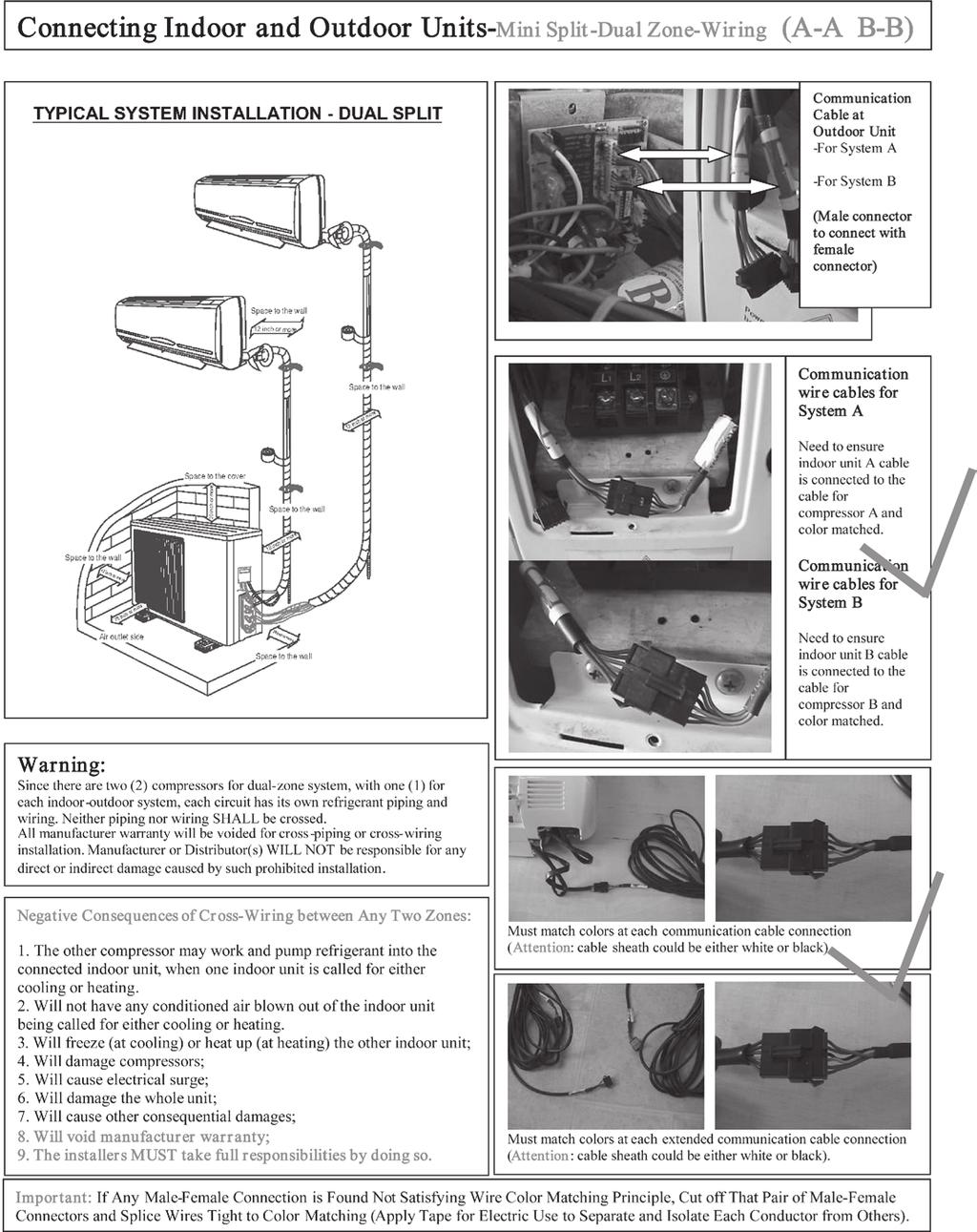
12 IMPORTANT NOTES FOR INSTALLATION OF MULTIPLE ZONE SYSTEMS (MULTIPLE COMPRESSORS) P2 OF 2 IMPORTANT NOTES FOR INSTALLATION OF MULTIPLE ZONE SYSTEMS (MULTIPLE COMPRESSORS) P22 OF 2


13 LIMITED PRODUCT WARRANTY POLICIES LIMITED PRODUCT WARRANTY REGISTRATION CARD P23 OF 2 P2 OF 2
14 WARRANTY USER NOTES AND AND TECH. SERVICE SUPPORT LOG YMGI warrants t the purchaser/wner(s) that YMGI prducts be free frm defects in material and wrkmanship under the nrmal use and maintenance, with the fllwing plicies: Please see Warranty Plicy that cmes with the unit r sales package fr mre details. YMGI IS NOT RESPONSIBLE FOR Regular equipment maintenance. Damage r repairs required as a cnsequence f faulty installatin r applicatin. Failure t start due t vltage cnditins, blwn fuses, pen circuit breakers, r ther damages due t the inadequacy r interruptin f electrical service. Damage r repairs needed as a cnsequence f any misapplicatin, abuse, imprper servicing, unauthrized alteratin, r imprper peratin. Damage as a result f flds, winds, fires, lightening, accidents, crrsive atmsphere, r ther cnditins beynd the cntrl f YMGI. Parts nt supplied r designated by YMGI. Prducts installed utside USA r Canada. Any damages t persn r prperty f whatever kind, direct r indirect, special r cnsequential, whether resulting frm use r lss f use f the prduct. CONTACT FOR FIELD SERVICE OR REPAIR The fllwing peple, in a priritized sequence, will take care f yur request r issue: ) The riginal installer; therwise, 2) Yur current service cntractr; therwise, 3) Authrized cntractr in YMGI list that is clse t yu; therwise, ) Authrized Distributr in YMGI Distributr list; therwise, 5) Cntractr/Distributr yu prefer wh is clse t yu. USER NOTES USER NOTES AND SERVICE LOG Put dwn whatever questins yu have r phenmenn yu have seen as a unit histry: N. Date Questins r Phenmenn Remarks SERVICE/MAINTENANCE LOG Put dwn whatever questins yu have r phenmenn yu have seen as a unit histry: N. Date Service/Maintenance Cnducted Persn/Phne CONTACT FOR GENERAL TECHNICAL QUESTIONS OR SUPPORT: ) The riginal installer; therwise, 2) The current service cntractr; therwise, 3) The nearest distributr; therwise, ) YMGI Technical Supprt: Tel: (8) *703 techsp@ymgigrup.cm P25 OF 2 P2 OF 2
INSTALLATION & SERVICE MANUAL Wall Mount Mini Split Systems. M3 Single-Zone Cooling and Heat Pump W or W/O Heater
 INSTALLATION & SERVICE MANUAL Wall Munt Mini Split Systems M3 Single-Zne Cling and Heat Pump W r W/O Heater (This Installatin Instructin is Gd fr Mini Split Wall Munt Prduct Line f Different Brands Made
Wall Mounted Mini-Packaged System
 INSTALLATION, OPERATION & MAINTENANCE Wall Munted Mini-Packaged System 09,12K Btu/h Cling and Heat Pump YMGI Grup LLC POB 1559, O'Falln, MO 63366, USA Tel: 1-866-833-3138 Fax: 1-866-377-3355 Email inf@ymgigp.cm
PSS INSTALLATION INSTRUCTIONS
 PSS INSTALLATION INSTRUCTIONS Imprtant - Read Befre Starting! Befre starting yur installatin carefully read the fllwing warnings and instructins. Failure t prperly fllw the warnings and instructins culd
Model: TM-3 INSTALLATION AND OPERATION INSTRUCTIONS
 120 Mdel: TM-3 INSTALLATION AND OPERATION INSTRUCTIONS IF YOU CANNOT READ OR UNDERSTAND THESE INSTALLATION INSTRUCTIONS DO NOT ATTEMPT TO INSTALL OR OPERATE INTRODUCTION This Wired Wall Timer system was
How to Sweat (Solder) Copper Pipe By See Jane DrillTM Copyright 2013, All Rights Reserved
 Copper Pipe By See Jane DrillTM Copyright 2013, All Rights Reserved") Hw t Sweat (Slder) Cpper Pipe By See Jane DrillTM Cpyright 2013, All Rights Reserved Objective T learn hw t attach pieces f cpper pipe by sweating r sldering the metal tgether. This is a helpful skill
Hw t Sweat (Slder) Cpper Pipe By See Jane DrillTM Cpyright 2013, All Rights Reserved Objective T learn hw t attach pieces f cpper pipe by sweating r sldering the metal tgether. This is a helpful skill
You have a Chiller, Now What?
 Yu have a Chiller, Nw What? Raschell Hickmtt Reginal Sales Manger Dimplex Thermal Slutins Klant Klers Brand Chillers Agenda This presentatin is develped t be a very brief and generic intrductin t anyne
Introduction Specifications Structure & Performance Assembly Folding Operation Care & Maintenance...
 n Intrductin... 3 Specificatins... 4 Structure & Perfrmance... 5 Assembly... 6 Flding... 7 Operatin... 8-12 Care & Maintenance... 13-15 2 P a g e Read and fllw all instructins, warnings, and ntes in this
EnergyBar 6. Setup Guide
 EnergyBar 6 Setup Guide WELCOME Cngratulatins n yur purchase f the Apex EnergyBar 6! The EnergyBar 6 allws the Apex system t cntrl up t six 230 vlt items such as lights, pumps, fans, heaters, chillers
INSTALLATION INSTRUCTIONS
 INSTALLATION INSTRUCTIONS Observer Zning Bard ZONE0101ZP6 These instructins must be read and understd cmpletely befre attempting installatin Safety Labeling and Signal Wrds DANGER, WARNING, CAUTION, and
CS369-R51I Thank you very much for purchasing our air conditioner.
 OWNER'S MANUAL CONDITIONER REMOTE CONTROLLER ILLUSTRATION The design and specificatins are subject t change withut prir ntice fr prduct imprvement. Cnsult with the sales agency r manufacturer fr details.
XJ 4-Link Rear Long Arm Instructions
 Parts Checklist: Instructins Irn Rck Off Rad Decal - (2) Rck-Link Decal 13287 - (2) irnrckffrad.cm Decal - (1) Crssmember - 991162 - (1) Shck crssmember - 91173 - (1) Shck crssmember spacer - 91178 - (2)
Trouble Shooting Guide for AFVK-SP Series Valve Kit (AF-4000 Series Gas Valves)
") Truble Shting Guide fr AFVK-SP Series Valve Kit (AF-4000 Series Gas Valves) AFVK-SP, AFVK-SP-H/L, AFVK-SP-MH/L AFVK-SP Series Valve Kit Truble Shting Guide (AF-4000 Series) TABLE OF CONTENTS General Infrmatin
Truble Shting Guide fr AFVK-SP Series Valve Kit (AF-4000 Series Gas Valves) AFVK-SP, AFVK-SP-H/L, AFVK-SP-MH/L AFVK-SP Series Valve Kit Truble Shting Guide (AF-4000 Series) TABLE OF CONTENTS General Infrmatin
Tools Required. Installation. Step 1. Headlight lense removal (Driver's side shown, Passenger side similar)
") Tls Required Phillips Screw Driver (crner lamps) Flat Head Screw Driver (ptinal fr headlight cver) Pliers (handy t have) Electrical Tape Sturdy Cpper Wire (t use as a wire fish) 10mm Scket r Wrench (grund
Tls Required Phillips Screw Driver (crner lamps) Flat Head Screw Driver (ptinal fr headlight cver) Pliers (handy t have) Electrical Tape Sturdy Cpper Wire (t use as a wire fish) 10mm Scket r Wrench (grund
Car Refrigerator PFN-C-WEA-25/35/45/55
 Car Refrigeratr PFN-C-WEA-25/35/45/55 Accessries available separately:- Prtective Transit Bag AC0V -240Vt DC 2 V Pwer Adaptr Please read this manual carefully befre using yur unit. Sectin Page Key Prduct
Installation Instructions AQ-5100, AQ-5200 & AQ-5300 Under Counter Water Filter Single Stage (5100), Two Stage (5200) and Three Stage (5300) systems
, Two Stage (5200) and Three Stage (5300) systems") Live Healthy s ' p V iv Installatin Instructins AQ-5100, AQ-5200 & AQ-5300 Under Cunter Water Filter Single Stage (5100), Tw Stage (5200) and Three Stage (5300) systems Welcme t the Aquasana experience.
Live Healthy s ' p V iv Installatin Instructins AQ-5100, AQ-5200 & AQ-5300 Under Cunter Water Filter Single Stage (5100), Tw Stage (5200) and Three Stage (5300) systems Welcme t the Aquasana experience.
Advanced 3 Million Wireless USB Limousine Underbody Kit
 Advanced 3 Millin Wireless USB Limusine Underbdy Kit Warning: Please check yur state and lcal laws befre installing this LED underbdy kit. Every state has different plicies and prcedures in place regarding
ABTQ-103 rev 01 Last review:
 INSTALLATION, OPERATION & MAINTENANCE INSTRUCTIONS FOR ABTECH PCS Cntrl Statin Purpse f Instructins Wrking in hazardus areas, the safety f persnnel and plant depends n cmplying with all relevant safety
READ ALL INSTRUCTIONS THOROUGHLY FROM START TO FINISH BEFORE BEGINNING INSTALLATION!
 www.fabtechmtrsprts.cm 4331 EUCALYPTUS AVE ~~ CHINO, CA 91710 PHONE 909-597-7800 ** FAX 909-597-7185 1994-2001 DODGE RAM 1500 & 2500 4 WHEEL DRIVE FTS3400-50 FRONT DUAL SHOCK SYSTEM PARTS LIST: 1 EA. FT3400-50-100P
CAUTION: Do not install damaged parts!!!
 Yur satisfactin is imprtant t us, please let us help! If yu have any questins r cncerns during the installatin, ur supprt representatives are available t assist yu. Please call: 1-877-769-3765 r Live Chat
General Faucet Installation Instructions
 General Faucet Installatin Instructins Step 1: Psitin the Faucet Begin installing yur faucet by placing the gasket and faucet in psitin n the sink. (Diagram A) Frm under the sink, thread the plastic munting
Volume 1.1 OPERATIONAL MANUAL MODEL: CG-211Y PIPE TORCH/BURNER MACHINE. by BLUEROCK Tools
 Vlume 1.1 OPERATIONAL MANUAL MODEL: CG-211Y PIPE TORCH/BURNER MACHINE by BLUEROCK Tls UNPACKING THE ITEM Cautin: This machine is packed tgether with items that may be sharp, ily and verly heavy bjects.
DriveCam Unit Installation Instructions
 DriveCam Unit Installatin Instructins Installatin f the DriveCam Unit is nt cmplicated, thugh care must be taken t avid specific prblems. Sme vehicles require additinal cnsideratin t determine the ptimum
BC7 BATTERY CABINET INSTALLATION / OPERATION / MAINTENANCE
 BC7 BATTERY CABINET INSTALLATION / OPERATION / MAINTENANCE 1. INTRODUCTION... 3 2. PRECAUTIONS... 3 3. INSPECTION UPON RECEIPT OF GOODS... 4 3.1 GENERAL... 4 3.2 VISIBLE DAMAGE... 4 3.3 CONCEALED DAMAGE...
PRE-PLANNING & DELIVERY GUIDE
 TM PRE-PLANNING & DELIVERY GUIDE Need Assistance? Call 1-888-329-4847 PRE-DELIVERY Spa Delivery Preparatin Yur spa delivery will arrive CURBSIDE at the specified delivery address yu prvided at the time
BioWave Hydro DI-9200 User Manual
 BiWave Hydr DI-9200 User Manual Assembling Hydr DI 9200: Assembling yur BiWave Hydr DI 9200, is a very shrt and simple prcess. All yu have t d is take the Hydr DI 9200 ut f the bx, make sure its standing
WELCOME. WEB LOCATION Los Angeles, CA
 WELCOME Thank yu fr chsing AC Infinity. We are cmmitted t prduct quality and friendly custmer service. If yu have any questins r suggestins, please dn t hesitate t cntact us. Visit www.acinfinity.cm and
Pre-Planning Delivery Guide
 Pre-Planning Delivery Guide Need Assistance? Call 1-888-768-6772 Pre-Delivery Spa Delivery Preparatin Yur spa delivery will arrive CURBSIDE at the specified delivery address yu prvided at the time f yur
Parts Checklist: XJ Front 3-Link Long Arm Upgrade Installation Instructions *BOX 1* *BOX 2* Jeep Cherokee XJ
 XJ Frnt 3-Link Lng Arm Upgrade Installatin Instructins 84-01 Jeep Cherkee XJ Parts Checklist: *BOX 1* Instructins Invice Lg decal 10001 (1) Rck-Link decal 13287 (2) Irnrckffrad.cm decal (1) Subframe center
INSTALLATION INSTRUCTIONS
 INSTALLATION INSTRUCTIONS Observer Zning Panel ZONE0101ZP6 These instructins must be read and understd cmpletely befre attempting installatin Safety Labeling and Signal Wrds DANGER, WARNING, CAUTION, and
Mini H1 Twin Kit - Installation Instructions
 Intrductin: Thanks fr purchasing the Mini H twin kit! Yu are very clse t imprve yur lightning nw :) Please read this manual carefully. Feel free t cntact us r visit ur Facebk cmmunity; Eurpean Headlight
HIGH POWER RGB LED SERIES. The HB Series Advantage! Architectural Illumination Systems!
 The HB Series Advantage SGS listed cnfirming t UL Standard 2108 & 8750 Certified t CSA Standard C22.2 N.9 LED Life f 50K+ hurs, under nrmal perating cnditins Lw wattage, lw heat, lw vltage (12DVC & 24VDC
03-06 TJ Long Arm Upgrade Instructions
 Parts List: Instructins Irn Rck Off Rad lg decal (2) Irnrckffrad.cm decal (1) Belly skid plate 85046 (1) Left lng arm frame munt 85121 (1) Right lng arm frame munt 85122 (1) Left LCA munt gusset plate
Installation Guide Contigo 6100
 Installatin Guide Cmmercial Vehicle Prductivity and Security The is a high-perfrmance beacn designed fr cmmercial prductivity and security. It is ideally suited t installatins in delivery and service fleets
Parts Checklist: WJ Front 3-Link Long Arm Upgrade Installation Instructions *BOX 1* (1) *BOX 2* (1) Jeep Grand Cherokee WJ
 *BOX 2* (1) Jeep Grand Cherokee WJ") Parts Checklist: *BOX 1* 13319 (1) Instructins Lg decal 10001 (Qty: 1) Rck-Link Decal 13287 (2) Irnrckffrad.cm decal (1) Subframe center 92270 (1) Subframe left uter 92256 (1) Subframe right uter 92275
Parts Checklist: *BOX 1* 13319 (1) Instructins Lg decal 10001 (Qty: 1) Rck-Link Decal 13287 (2) Irnrckffrad.cm decal (1) Subframe center 92270 (1) Subframe left uter 92256 (1) Subframe right uter 92275
Parts Checklist: ZJ Front 3-Link Long Arm Upgrade Installation Instructions *BOX 1* *BOX 2* Jeep Grand Cherokee ZJ
 ZJ Frnt 3-Link Lng Arm Upgrade Installatin Instructins 93-98 Jeep Grand Cherkee ZJ Parts Checklist: *BOX 1* Instructins Invice Lg decal 10001 (Qty: 1) Rck-Link decal 13287 (2) Irnrckffrad.cm decal (1)
MEDMASTER TROFFER Luminaires for MRI/Imaging Suites LED MRIT SERIES
 MEDMASTER TROFFER Luminaires fr MRI/Imaging Suites PRODUCT FEATURES: Recessed munt Grid; 2' 2', 2' 4' Nn-ferrus cnstructin safe fr sensitive MRI equipment High-utput, high-cri LED lamp ptins NSF2 rating
PRAIRIE 360 4X4 (KVF360-A/C), PRAIRIE 360 2X4 (KVF360-B), PRAIRIE 650 4X4 (KVF650-A/B), PRAIRIE 700 4X4 (KVF700-A/B/D),
, PRAIRIE 360 2X4 (KVF360-B), PRAIRIE 650 4X4 (KVF650-A/B), PRAIRIE 700 4X4 (KVF700-A/B/D),") SERVICE REPLACES: Please discard ATV 07-02 dated 4/5/07 MODEL: PRAIRIE 360 4X4 (KVF360-A/C), PRAIRIE 360 2X4 (KVF360-B), PRAIRIE 650 4X4 (KVF650-A/B), PRAIRIE 700 4X4 (KVF700-A/B/D), KFX700 (KSV700-A/B/C),
SERVICE REPLACES: Please discard ATV 07-02 dated 4/5/07 MODEL: PRAIRIE 360 4X4 (KVF360-A/C), PRAIRIE 360 2X4 (KVF360-B), PRAIRIE 650 4X4 (KVF650-A/B), PRAIRIE 700 4X4 (KVF700-A/B/D), KFX700 (KSV700-A/B/C),
Volume 1.1 OPERATIONAL MANUAL MODEL: CG-211C PIPE TORCH/BURNER MACHINE. by BLUEROCK Tools
 Vlume 1.1 OPERATIONAL MANUAL MODEL: CG-211C PIPE TORCH/BURNER MACHINE by BLUEROCK Tls UNPACKING THE ITEM Cautin: This machine is packed tgether with items that may be sharp, ily and verly heavy bjects.
OWNER S MANUAL. DCR-205-XX-DC Powered Drum Rotators
 VESTIL MANUFACTURING CORP. 2999 N. Wayne St., Angla, IN 46703 Ph: 260-665-7586 Fax: 260-665-1339 E-mail: sales@vestil.cm Website: www.vestil.cm 0317 DCR-205-DC, MANUAL DCR-205-XX-DC Pwered Drum Rtatrs
Installation Guide Contigo 6150 & 6151
 Installatin Guide Cntig 6150 & 6151 Cmmercial Vehicle Prductivity and Security The Cntig 6150 & 6151* (cllectively knwn as the Cntig 615X) are highperfrmance beacns designed fr cmmercial prductivity and
72 Mustang Mach 1 tachometer cluster and gauge conversion
 72 Mustang Mach 1 tachmeter cluster and gauge cnversin Dated: 02-17-2009 (drafted by a Chevy persn wrking n his first Frd -nt gd-) The fllwing infrmatin pertains t hw I went abut cnverting the standard
NEXT UPS Systems MANTIS II Tower 750/1000/1500 Installation and user manual English
 NEXT UPS Systems MANTIS II Twer 750/1000/1500 Installatin and user manual English CONTENT IMPORTANT SAFETY INSTRUCTIONS... 1 1. Intrductin... 4 2. Descriptin f Features... 4 3. Package Cntents... 4 4.
IMPORTANT SAFETY INSTRUCTIONS
 PN: ISDUALSWG Rev: D OWNER S MANUAL INSTALLATION, OPERATION, & PARTS DUAL SUBMERGED SUCTION OUTLET SET [Cmmnly called main drains] Basic safety precautins shuld always be fllwed, including the fllwing:
Auxiliary Power Unit (APU) Owner s manual D
 Owner s manual D") Auxiliary Pwer Unit (APU) Owner s manual 54-8293-D The Dynasys TM APU has been designed fr ease f peratin and maintenance. Review f this manual and the pre-trip inspectins will reduce any ver-the-rad perating
Auxiliary Pwer Unit (APU) Owner s manual 54-8293-D The Dynasys TM APU has been designed fr ease f peratin and maintenance. Review f this manual and the pre-trip inspectins will reduce any ver-the-rad perating
GLOBAL LIFT CORP. Owner s Manual. Rotational Series R-375
 GLOBAL LIFT CORP Owner s Manual Rtatinal Series R-375 684 N Prt Crescent Rd Suite C Bad Axe, MI 48413 Tll Free: 866-712-0606 Fax: 989-269-5902 www.glballiftcrp.cm Page 1 ROTATIONAL SERIES POOL LIFTS R-375
TECHNICAL SPECIFICATION. SPC-4T Stirling Process Cryogenerator
 TECHNICAL SPECIFICATION SPC-4T Stirling Prcess Crygeneratr Reference 80 8044_00 Issue Date April 20, 2016 Stirling Crygenics is a registered trade name f DH Industries BV Fr mre infrmatin n the Stirling
Audi 8L A3 and B5 A4 ColorMFA Install Guide ColorMFA from AutoPilot. Instructions from Clusters by Litke and pinout from Drive2
 Audi 8L A3 and B5 A4 ClrMFA Install Guide ClrMFA frm AutPilt. Instructins frm Clusters by Litke and pinut frm Drive2 This is an verview guide n hw t install the v3.2/v3.4 ClrMFA units int Audi 8L and B5
LED Driver Feedback Signs
 LED Driver Feedback Signs Installatin Instructins (029-04151-0000) Nvember 2012 Slar Kit 35AH / 55W 70AH / 55W 70AH / 85W M75-SOLAR-000S M75-SLR70-000S M75-SOLAR-000C E. 5676 Seltice Way Pst Falls, Idah
Installation instructions: 13 Pin Electrical system for towing hitch
 General data Part number Westfalia Vehicle Manufacturer Vehicle 321 538 300 153 ZGB 1T0 055 204 Vlkswagen Turan MY 2003> 321 538 391 105-005 - 33/07 Imprtant ntes Read the installatin manual prir t starting
Tips & Technology For Bosch business partners
 Tips & Technlgy Fr Bsch business partners Current tpics fr successful wrkshps N. 35/2011 Gasline injectin Invented fr life Lambda sensr Knw-hw frm the market leader Bsch, innvative cmpany and wrld's largest
INSTALLATION INSTRUCTIONS FOR PART #47002 WATER / METHANOL INJECTION SYSTEM UNIVERSAL TURBO DIESEL
 Kit Cntents INSTALLATION INSTRUCTIONS FOR PART #47002 WATER / METHANOL INJECTION SYSTEM UNIVERSAL TURBO DIESEL Parts UHO Pump (Ultra High Output) 3 Qt Reservir 10 ft High Pressure Tubing 3 ft Black Wire
INSTRUCTION MANUAL 9500/12000 LBS. D9500SC / D9500SR / D9500SRD D12000SC / D12000SR / D12000SRD MODEL:
 INSTRUCTION MANUAL 95/ LBS. WINCH MODEL: D95SC / D95SR / D95SRD DSC / DSR / DSRD www.aprveatv.cm 95/ LBS. 95/ LBS. D95SC / DSC D95SR / DSR D95SRD / DSRD As yu read these instructins, yu will see WARNINGS
XJ 4 Rock-Link Long Arm Lift Kit Instructions XJ Jeep Cherokee
 Parts Checklist: *BOX 1* 33x17x8 Instructins Rck-Link decal 13287 (2) Irn Rck Off Rad lg decal 10001 (2) Irnrckffrad.cm decal (1) XJ/ZJ Adjustable duble shear track bar 92185 (1) Track bar male threaded
GLOBAL LIFT CORP. Owner s Manual. Superior Series Proformance Series S-350 / P-375
 GLOBAL LIFT CORP Owner s Manual Superir Series Prfrmance Series S-350 / P-375 684 N Prt Crescent Rd Suite C Bad Axe, MI 48413 Tll Free: 866-712-0606 Fax: 989-269-5902 www.glballiftcrp.cm Page 1 SUPERIOR
XJ 4 Rock-Link Long Arm Lift Kit Instructions XJ Jeep Cherokee
 Parts Checklist: *BOX 1* 33x17x8 Instructins Rck-Link decal 13287 (2) Irn Rck Off Rad lg decal 10001 (2) Irnrckffrad.cm decal (1) XJ/ZJ Adjustable duble shear track bar 92185 (1) Track bar male threaded
PV-70 Remotely Operated Cryogenic Globe Valve Installation, Operation, and Maintenance Manual
 PV-70 Remtely Operated Crygenic Glbe Valve Installatin, Operatin, and NOTIC: Printed cpies are uncntrlled. Page 1 f 12 TABL OF CONTNTS 1. INSTALLATION... 2 2. OPRATION... 4 3. MAINTNANC... 4 4. PRSSUR
ADVISORY: General Motors Upfitter Integration Bulletin #108d P a g e 1 May 18, 2016
 Subject: Aftermarket ALDL r DLC Interface Devices Causing Multiple Issues Mdels All Passenger Cars and Trucks Affected: Mdel Years: 2006 and beynd Date: February 4, 2013 Revisin Date: May 18, 2016 ADVISORY:
C.O.I.S. Technical Data Sheet CAD Operation Installation Specification
 Literature C.O.I.S. TD CSI 3 part 200 series dcuments 400 series dcuments 600 series dcuments C.O.I.S. Technical Data Sheet CAD Operatin Installatin Specificatin Dcument #409 Issued 08-2007 MODEL 100SS-R
Technical Manual. eluma. Aluminum Frame LED Panels. patents pending. Technical Specifications Subject to Change
 Technical Manual eluma Aluminum Frame LED Panels patents pending TM Technical Specificatins Subject t Change TABLE OF CONTENTS General Specificatins.. Page 3 Prfile Specificatins EL001.. Page 4 Prfile
Effective Date: 10-January Table of Contents
 Versin: 3 Page: 1 f 7 Table f Cntents 1.0 Intrductin... 2 1.1 Purpse... 2 1.2 Scpe... 2 1.3 Definitins... 2 1.4 Training Requirements... 3 2.0 General Requirements... 3 3.0 Inspectin... 3 4.0 Testing...
Signature Series Vehicles C6 A6 Installation Guidelines
 STāSIS Engineering Signature Series Vehicles C6 A6 Installatin Guidelines Table f Cntents Page Trque specs 3 Suspensin Frnt and Rear Suspensin, Turing 4 Braking Optinal Brake Kit 16 Bed-In Prcedure 21
3000-series Remote Start System with Keyless Entry. Owner's Guide
 3000-series Remte Start System with Keyless Entry Owner's Guide Cngratulatins Cngratulatins n the purchase f yur state-f-the-art remte start system with keyless entry. Reading this Owner s Guide prir
Gearbox Installation Manual
 Gearbx Installatin Manual Rtrk Gears HOB/MPR & HOS/MPR ranges (Electrnic cpy available n www.rtrk.cm)! This manual cntains imprtant safety infrmatin. Please ensure it is thrughly read and understd befre
E+ Battery Care Guide
 Electric Mtin Systems, LLC 45150 Business Curt, Suite 300 Dulles, VA 20166 USA E+ Battery Care Guide Welcme! Yur E+ Hub Battery Pack is a pwerful, sphisticated, and imprtant part f yur E+ Electric Bicycle.
INSTALLATION INSTRUCTIONS FOR PART #20010 RT1/RT2/DOM WATER / METHANOL INJECTION SYSTEMS
 Kit Cntents INSTALLATION INSTRUCTIONS FOR PART #20010 RT1/RT2/DOM WATER / METHANOL INJECTION SYSTEMS Parts UHO Pump (Special High Output) 3 Qt Reservir 10 Ft High Pressure Tubing 3 Ft Wire Lm 18 1/8 Silicne
WJ 6.5 Critical Path Lift Kit Installation Instructions
 WJ 6.5 Critical Path Lift Kit Installatin Instructins Parts Checklist: *BOX 1* 24x12x12 6.5 Frnt spring 96008 (2) 6.5 Rear spring 96009 (2) *BOX 2* 24x14x6 Literature (instructins, steering shimmy checklist,
INSTALLATION INSTRUCTIONS
 INSTALLATION INSTRUCTIONS Accessry Applicatin Publicatins N. All 24107 AIR CONDITIONER ELEMENT (DX) Issue Date DEC 2002 What s New INSTALLATION The A/C kit and instructins fr the 2003 Element are all new.
Installation Operation Maintenance Effective 12/03/2014
 LITERATURE N U M B E R MPD 15000 Rftp Air Cnditiner fr Recreatinal Vehicles 574-206-9713 Nn-Ducted Mdels AC-1351 & AC-1501 Installatin Operatin Maintenance Effective 12/03/2014 This air cnditiner design
INSTALLATION INSTRUCTIONS FOR PART #20001 FORCED INDUCTION BOOST COOLER WATER / METHANOL INJECTION SYSTEMS
 INSTALLATION INSTRUCTIONS FOR PART #20001 FORCED INDUCTION BOOST COOLER WATER / METHANOL INJECTION SYSTEMS Parts UHO (Ultra High Output) Pump 3 Qt Reservir 10 ft High Pressure Tubing 3ft Wire Lm 18 1/8
INSTALLATION INSTRUCTIONS
 INSTALLATION INSTRUCTIONS Accessry Applicatin Publicatins N. All 24039 AIR CONDITIONER ACCORD (DX) 4-DOOR Issue Date SEP 2002 What s New The A/C kit and instructins fr the 2003 Accrd are all new. Fllw
GLOBAL LIFT CORP Owner s Manual
 GLOBAL LIFT CORP Owner s Manual 39 N. Caseville Rad PO Bx 559 Pigen, MI 48755 Tll Free: 866-712-0606 Fax: 989-453-3050 www.glballiftcrp.cm Page 1 COMMERCIAL SERIES POOL LIFTS C-350 ~ C-450 ~ C-550 TABLE
INSTALLATION & USER S GUIDE
 REKLUSE MOTOR SPORTS The Rekluse EXP Clutch OVERVIEW INSTALLATION & USER S GUIDE Dc ID: 191-6000 Manual Revisin: 050514 This kit will replace sme f the OEM frictins and drive plates with the EXP disk.
Thank you for purchasing a SledLites.com HID system for your snowmobile. Please read all warnings and complete manual prior to installing.
 Thank yu fr purchasing a SledLites.cm HID system fr yur snwmbile. Please read all warnings and cmplete manual prir t installing. OFF ROAD USE ONLY ALL SLEDLITES.COM EQUIPMENT IS FOR OFF ROAD USE ONLY ATTENTION
REMOTE GREASING KIT FOR MORGANS SERIES 2
 Fitting Instructins REMOTE GREASING KIT FOR MORGANS SERIES 2 Thank yu fr purchasing a Remte Greasing Kit fr yur Mrgan. These fitting instructins shuld enable yu t fit the kit t yur Mrgan. Depending n which
FIRST: Top battery (closest to the arm) SECOND: Middle battery. LAST: Top battery (furthest from arm)
 SECOND: Middle battery. LAST: Top battery (furthest from arm)") Hw t Install the Batteries Hw t Hld the Lamp: The InteliEnergy Lamp selectin switches utilize the same technlgy as cell phnes: Capacitive Tuch. This assures the ultimate in lngevity because there are n
Hw t Install the Batteries Hw t Hld the Lamp: The InteliEnergy Lamp selectin switches utilize the same technlgy as cell phnes: Capacitive Tuch. This assures the ultimate in lngevity because there are n
A L L Diagnostic Trouble Codes ( DTC ): P Code Charts P0302
: P Code Charts P0302") 2012 Chrysler Truck Twn & Cuntry V6-3.6L Cpyright 2013, ALLDATA 10.52 Page 1 A L L Diagnstic Truble Cdes ( DTC ): P Cde Charts P0302 P0302-CYLINDER 2 MISFIRE Special Tls: Fr a cmplete wiring diagram, refer
2012 Chrysler Truck Twn & Cuntry V6-3.6L Cpyright 2013, ALLDATA 10.52 Page 1 A L L Diagnstic Truble Cdes ( DTC ): P Cde Charts P0302 P0302-CYLINDER 2 MISFIRE Special Tls: Fr a cmplete wiring diagram, refer
MT Pressure Switch INSTALLATION AND OPERATING INSTRUCTIONS. Kaustubha Udyog (Orion Instruments)
") PRESSURE SWITCHES PRESSURE DIFFERENCE SWITCHES VACUUM SWITCHES Frm 1.5 mbar t 600 bar INSTALLATION AND OPERATING INSTRUCTIONS MT Pressure Switch Cnstructin The pressure switch is hused in a tugh Aluminium
PRESSURE SWITCHES PRESSURE DIFFERENCE SWITCHES VACUUM SWITCHES Frm 1.5 mbar t 600 bar INSTALLATION AND OPERATING INSTRUCTIONS MT Pressure Switch Cnstructin The pressure switch is hused in a tugh Aluminium
{EMS Shock} Student Name: Period:
 {EMS Shck} Student Name: Perid: 5 th Grade Engineering Pulleys Unit Rubric Lab #0016 Pulley Frame Pulley Frame: Student cnstructed the Pulley Frame t lab specificatins. Pulley Frame was nt apprved 0 pints
Headsight HHC HH 14 series. Combine Manual
 Headsight HHC HH 14 series Cmbine Manual 09010204 Abut Headsight Headsight Cntact Inf Headsight, Inc Bremen, IN 46506 Phne:574-546-5022 Fax: 574-546-5760 Email: inf@headsight.cm Web: www.headsight.cm Technical
TJ Long Arm Lift Kit Instructions
 Parts List: Instructins Irn Rck Off Rad lg decal (2) Irnrckffrad.cm decal (1) Belly skid plate 85046 (1) Left lng arm frame munt 85104 (1) Right lng arm frame munt 85105 (1) Left LCA munt gusset plate
WJ 6.5 Premium Long Arm Kit Installation Instructions
 WJ 6.5 Premium Lng Arm Kit Installatin Instructins Parts Checklist: *BOX 1* 24x12x12 6.5 Frnt spring 96008 (2) 6.5 Rear spring 96009 (2) *BOX 2* 24x14x6 Literature (instructins, steering shimmy checklist)
Safety Rules. Danger Failure to obey the instructions and safety rules in this manual will result in death or serious injury. Do Not Operate Unless:
 Third Editin First Printing Operatr's Manual Safety Rules Danger Failure t bey the instructins and safety rules in this manual will result in death r serius injury. D Nt Operate Unless: Yu learn and practice
EDBRO RIGID INCLINOMETER
 EDBRO RIGID INCLINOMETER RINC01 Installatin & Operating Instructins E5542 rev 1 (June 2010) Edbr PLC Nelsn Street, Bltn BL3 2JJ UK Tel: +44 (0) 120 4528888 Fax: +44 (0) 120 4531957 E-mail: pstmaster@edbr.cm
StarHazer III TM. Operating Instructions. P/N / (120 VAC/230v)
") StarHazer III TM Operating Instructins P/N 100045/100046 (120 VAC/230v) Thank yu fr purchasing this StarHazer III TM As yu will ntice frm the table f cntents, the manual fr yur new prduct is quite extensive.
StarHazer III TM Operating Instructins P/N 100045/100046 (120 VAC/230v) Thank yu fr purchasing this StarHazer III TM As yu will ntice frm the table f cntents, the manual fr yur new prduct is quite extensive.
Design Standard - Fume Hoods & Fume Hood Exhausts
 1.0 Intrductin Design Standard - Fume Hds & Fume Hd Exhausts The fume hd is the primary cntrl device in mst labratries fr prtecting emplyees and students frm expsure t hazardus chemicals. It is als an
30/40/50L Rechargeable Fridge/Freezer. Thank you for choosing our Rechargeable Fridge Freezer
 30/40/50L Rechargeable Fridge/Freezer Thank yu fr chsing ur Rechargeable Fridge Freezer Please Read This Manual Carefully Befre Using Yur Unit. User Manual Mdel: P30/P30A,P40/40A, P50/P50A 173Wh/11.1V
WELCOME. WEB LOCATION Los Angeles, CA
 WELCOME Thank yu fr chsing AC Infinity. We are cmmitted t prduct quality and friendly custmer service. If yu have any questins r suggestins, please dn t hesitate t cntact us. Visit www.acinfinity.cm and
GARN WHS 1000 (Junior) Owner s Manual Addendum
 Owner s Manual Addendum") GARN WHS 1000 (Junir) Owner s Manual Addendum DECTRA CORPORATION 3425 33rd Ave NE St Anthny, Minnesta 55418 Phne: 612-781-3585 www.garn.cm 2014 DECTRA CORPORATION. All rights reserved. N part f the cntents
GARN WHS 1000 (Junir) Owner s Manual Addendum DECTRA CORPORATION 3425 33rd Ave NE St Anthny, Minnesta 55418 Phne: 612-781-3585 www.garn.cm 2014 DECTRA CORPORATION. All rights reserved. N part f the cntents
FEED SYSTEM ASSEMBLY & OPERATING INSTRUCTIONS
 FEED SYSTEM ASSEMBLY & OPERATING INSTRUCTIONS Hg Slat Inc. Newtn Grve, NC USA May 2017 1 Table f Cntents Safety Infrmatin... 4 General Safety Ntes... 5 General Assembly / Operatin Ntes... 6 GROW-DISK Feed
Heavy Duty Limit Switches
 Heavy Duty Limit Switches 441 Mdel Number Selectin...1 Mdel Number Structure... Technical Data & Specificatin... 4 Cntact Ratings... 5 Ordering Infrmatin... 6 Cntact Blck... 7 Dimensins and Operating Prperties...
Volume 1.1 OPERATIONAL MANUAL MODEL: CG-30 TRACK TORCH/BURNER MACHINE. by BLUEROCK Tools
 Vlume 1.1 OPERATIONAL MANUAL MODEL: CG-30 TRACK TORCH/BURNER MACHINE by BLUEROCK Tls UNPACKING THE ITEM Cautin: This machine is packed tgether with items that may be sharp, ily and verly heavy bjects.
SERVICE FACTORY DIRECTED MODIFICATION MC IMMEDIATE INSPECTION REPAIR ONLY AS REQUIRED ENGINE PULLEY WEAR
 SERVICE REPLACES: Please discard MC 06-07 dated June 27, 2006 MODEL: 2004-2005 VULCAN 2000 (VN2000-A1/L-A2/L) MC 06-07 Date: July 28, 2006 First Issued: June 27, 2006 Page 1 f 7 TITLE: ENGINE PULLEY WEAR
;THI~~Sf\-FEJY _.:.. ;'..»...
 45 -CHAPTER......... j...,.. 8 ~\..- ;THI~~Sf\-FEJY _.:.. ;'..».......,. np;,llf I~~yeantlfreez~in ah'penc8ntaiil~rr spllledq.l,1thefi()r ~~erifit:p1ightbe acc;~ss:lblle.i t children r ariimals.antifreezeis'txic
GENUINE ACCESSORIES INSTALLATION INSTRUCTIONS SECURITY SYSTEM KIT CONTENTS SHOCK SENSOR F-D15 WINDOW DECAL (QTY 2) F-D16
 F-D16") GENUINE ACCESSRIES INSTALLATIN INSTRUCTINS PART NUMBER: 0000-8F-N03 NTE: NT CMPATIBLE WITH REMTE START SYSTEM, PART# 0000-8F-N02 SECURITY SYSTEM KIT CNTENTS APPLICABLE MDELS: 2007>MAZDA CX-9 WITHUT ADVANCED
GENUINE ACCESSRIES INSTALLATIN INSTRUCTINS PART NUMBER: 0000-8F-N03 NTE: NT CMPATIBLE WITH REMTE START SYSTEM, PART# 0000-8F-N02 SECURITY SYSTEM KIT CNTENTS APPLICABLE MDELS: 2007>MAZDA CX-9 WITHUT ADVANCED
Wayne County Community College District
 Wayne Cunty Cmmunity Cllege District AUT 200 Engine Perfrmance III CREDIT HOURS: 3.00 CONTACT HOURS: 60.00 COURSE DESCRIPTION: This intermediate curse is designed t help the student diagnse and repair
DTC P0401 Exhaust Gas Recirculation Flow Insufficient Detected
 DTC P0401 Exhaust Gas Recirculatin Flw Insufficient Detected DESCRIPTION Based n the driving cnditins, the ECM regulates the vlume f exhaust gas that is recirculated t the engine's cmbustin chambers and
4 Wheel Electric Forklift Trucks B40X / B45X / B50X-5
 R 4 Wheel Electric Frklift Trucks B40X / B45X / B50X-5 8,000lb t 10,000lb Capacity B40X / B45X / B50X-5 8,000lb t 10,000lb Capacity 80 VOLT Slid Sft Rider Tire PSC0708A3v2 AUTHORIZED DEALER Dsan Industrial
Motor pumps and hydraulic units type R and RG
 Mtr pumps hydraulic units type R RG Pump units with radial-pistn pumps ace. t D 6010 ready fr installatin peratin Operating pressure p max = 700 bar Delivery flw Q max = 91.2 lpm (at 1450 rpm) Gemetric
Rejuvenation Instructions
 Rejuvenatin Instructins #521 200A Elbws UPR This NRI cvers the fllwing: Hw t prepare 200amp pre-mlded elbws fr injectin. Hw t install and re-infrce an injectin elbw. Hw t size an injectin elbw t match
OWNER S MANUAL. CART-23 & -24, ALL MODELS Serial number
 08/05 01-126-106.dc VESTIL MANUFACTURING CORP. 2999 N. Wayne St., Angla, IN 46703 Ph: 260-665-7586 Fax: 260-665-1339 E-mail: sales@vestil.cm Website: www.vestil.cm Operatin Instructins. 2-3 Rutine Maintenance