TECHNICAL MANUAL FOR ENGINE, DIESEL, WITH ACCESSORIES CUMMINS MODEL V8-300 ( )
|
|
|
- Molly Parks
- 5 years ago
- Views:
Transcription
1 TM TECHNICAL MANUAL DIRECT SUPPORT AND GENERAL SUPPORT MAINTENANCE MANUAL (INCLUDING DIRECT SUPPORT, AND GENERAL SUPPORT REPAIR PARTS LIST AND DEPOT MAINTENANCE ALLOWANCES) FOR ENGINE, DIESEL, WITH ACCESSORIES CUMMINS MODEL V8-300 ( ) This copy is a reprint which includes current pages from Changes 1 and 2. HEADQUARTERS, DEPARTMENT OF THE ARMY FEBRUARY 1972
2 } TM C2 CHANGE HEADQUARTERS DEPARTMENT OF THE ARMY No. 2 WASHINGTON, DC, 26 November 1976 Direct Support and General Support Maintenance Manual (Including Direct Support, and General Support Repair Parts and Special Tools List For ENGINE, DIESEL, WITH ACCESSORIES CUMMINS MODEL V8-300 ( ) Current as of 6 April 1976 TM , 2 February 1972, is changed as follows: 1. Remove old pages and insert new pages as indicated below. New or changed material is indicated by a vertical bar in the margin of the page. Added or revised illustrations are indicated by a vertical bar next to the identification number. Remove pages Insert pages 3-9and and and and and and and and and and 3-68 B-7 through B-18 B-7 through B-18 B-21 through B-24 B-21 through B-24 B-43 and B-44 B-43 and B-44 B-61 and B-62 B-61 and B-62 B-67 through B-87 B-77 through B File this change sheet in front of the publication for reference purposes.
3 TM By Order of the Secretary of the Army: Official: BERNARD W. ROGERS General, United States Army Chief of Staff PAUL T. SMITH Major General, United States Army The Adjutant General Distribution: To be distributed in accordance with DA Form 12-38, Direct/General Support TM requirements for 10-ton truck tractor, M123, M123AlC, M123C, M123E2 and Cargo Truck, M125.
4 } TM C1 CHANGE HEADQUARTERS DEPARTMENT OF THE ARMY No. 1 WASHINGTON, DC, 23 July 1975 Direct Support and General Support Maintenance Manual (Including Direct Support, and General Support Repair Parts and Special Tools List) For ENGINE, DIESEL, WITH ACCESSORIES CUMMINS MODEL V8-300 ( ) Current as of 7 April 1975 TM , 2 February 1972, is changed as follows: 1. Remove old pages and insert new pages as indicated below. New or changed material in the maintenance portion is indicated by a vertical bar in the margin of the page. Added or revised illustrations are indicated by a vertical bar next to the identification number. Remove pages Insert pages 3-57 and and and and 3-62 B-1 thru B-38 B-1 thru B-27 B-59 and B-60 B-59 and B-60 None B-62.1 B-77 thru B-89 B-77 thru B File this change sheet in front of the publication for reference purposes. By Order of the Secretary of the Army: Official: VERNE L. BOWERS Major General, United States Army, The Adjutant General. FRED C. WEYAND General, United States Army, Chief of Staff. Distribution: To be distributed in accordance with DA Form 12-38, (qty rqr block No. 92). Direct and General Support maintenance requirements for Truck, Tractor, 10-Ton, 6x6 M123A/C and M123E2.
5 } TM TECHNICAL MANUAL HEADQUARTERS DEPARTMENT OF THE ARMY No Washington D.C., 2 February 1972 DIRECT SUPPORT AND GENERAL SUPPORT MAINTENANCE MANUAL (INCLUDING DIRECT SUPPORT AND GENERAL SUPPORT REPAIR PARTS LIST AND DEPOT MAINTENANCE ALLOWANCES) FOR ENGINE, DIESEL, WITH ACCESSORIES CUMMINS MODEL V8-300 ( ) Paragraph Page CHAPTER 1. INTRODUCTION Section I. General II. Description and Data CHAPTER 2. MAINTENANCE INSTRUCTIONS Section I. Repair Parts, Special Tools and Equipment II. General Maintenance III. Removal of Engine Components CHAPTER 3. REPAIR INSTRUCTIONS Section I. General II. Repair of Cylinder Block III. Repair of Crankshaft IV. Repair of Connecting Rod and Piston Assembly V. Repair of Front Cover VI. Repair of Oil Pump Assembly VII. Repair of Camshaft VIII. Repair of Crankshaft Adapter IX. Repair of Flywheel Housing and Spacer Plate X. Repair of Oil Pan XI. Repair of Flywheel XII. Repair of Valve and Injector Tappets XIII. Repair of Cylinder Head XIV. Repair of Fuel Injectors XV. Repair of Rocker Arm Assembly and Push Rods XVI. Repair of Push Rod Cavity Covers XVII. Repair of Cylinder Head Covers XVIII. Repair of Air Compressor and Drive Assembly XIX. Repair of Fuel Pump and Fuel Lines XX. Repair of Water Crossover Pipe and Lifting Eyes XXI. Repair of Air Intake, Preheater Assembly and Intake Manifolds XXII. Repair of Water Pump Assembly XXIII. Repair of Fan Drive Pulley, Vibration Damper and Water Pump Pulley Assembly XXIV. Repair of Thermostat Assembly XXV. Repair of Fan, Fan Hub, and Bracket Assembly XXVI. Repair of Hydraulic Pump and Mounting Brackets XXVII. Repair of Alternator Assembly and Mounting Bracket XXVIII. Repair of Starter Assembly *This manual supersedes TM , 13 April 1966 including all changes. i
6 Paragraph Page CHAPTER 3. REPAIR INSTRUCTIONS--Continued XXIX. Repair of Oil Cooler XXX. Repair of Exhaust Manifolds XXXI. Engine Removal from Engine Rebuild Stand XXXII. Engine Test and Adjustment XXXIII. Repair and Rebuild Standards APPENDIX A. REFERENCES B. REPAIR PARTS AND SPECIAL TOOLS LIST Section I. Introduction B-1 II. Repair Parts List B-4 Group 01 -ENGINE 0100 Engine Assembly B Block and Cylinder Head B Crankshaft B Flywheel Assembly B Piston and Connecting Rod B Valves and Camshaft B Engine Lubrication System B Manifolds B-13 Group 03 -FUEL SYSTEM 0301 Fuel Injector B Fuel Pump B Air Cleaner B Starting Aids B-20 Group 05 -COOLING SYSTEM 0503 Thermostat B Water Pump B Fan Assembly B-22 Group 06 -ELECTRICAL SYSTEM 0601 Generator B-22 Group 12 -BRAKES 1209 Air Compressor and Drive Mechanism B-23 Group 14 -STEERING 1410 Hydraulic Pump Assembly B-23 Group 33 -SPECIAL PURPOSE KITS 3301 Reusable Shipping Containers B-24 Group 47 -GAGES 4701 Tachometer B-24 Section III. Special Tools List Group 26 -TOOLS AND TEST EQUIPMENT 2604 Special Tools B Test Equipment B-27 Section IV. Index-Federal Stock Number and Reference Number Cross-Reference to Figure and Item Number Index-1 ii
7 LIST OF ILLUSTRATIONS Number Title Page Number Title Page 1-1. Model V Engine Assembly 3/4 Left Piston Ring Gap Check Front View Rod Side Clearance Check Model V8-300 Engine Assembly 3/4 Right Crankshaft Oil Seal-Removal/Installation Rear View Front Cover Bore Alinement Check Engine Assembly Rear Sectional View Front Cover to Block Alinement Check Exhaust Manifold-Removal/Installation Drive Gear Backlash Check Oil Cooler-Removal Installation Camshaft End Play Check Engine Rebuild Stand-Removal/ Crankshaft Gear Backlash Check Installation Crankshaft Adapter Tightening Sequence Fan Hub and Bracket Assembly Flywheel Housing Concentricity Check Removal/Installation Flywheel Tightening Sequence Thermostat Assembly-Removal/ Flywheel Bearing Bore and Wobble Limits 3-14 Installation Tappet Assembly Test Drive Pulleys and Vibration Damper Cylinder Head in Holding Fixture Removal/Installation Valve Assemblies-Removal/Installation Water Pump Assembly-Removal Injector Sleeves-Removal/Installation Installation Crosshead Guide-Removal/Installation Air Intake Crossover and Preheater Valve Seat Removal Sectional View Assembly-Removal/Installation Injector Sleeve Holder Installation Intake Manifold, Fuel Pump and Fuel Injector Tip Protrusion Measurement Lines-Removal/Installation Valve Head and Collet Check Water Crossover Pipe and Lifting Eye Crosshead Guide Check Removal/Installation Valve Guide Check Oil Dipstick Tube Assembly-Removal/ Valve Spring Test Installation Valve and Injector Counterbore Measure Cylinder Head Covers-Removal/... ments Installation Cylinder Head Regrooving Crankcase Breather Tube Removal/ Valve Guide Installation Installation Crosshead Guide Installation Push Rod Cavity Covers-Removal/ Injector Sleeve Installation Installation Injector Sleeve Rolling-Upper Portion Rocker Arms and Push Rods-Removal/ Injector Sleeve Rolling-Lower Portion Installation Injector Sleeve Seat Cutting Injector Clamps Removal/Installation Valve Seat Insert Counterbore Fuel Injector and Hold-Down Clamp Intake Valve Port Swirl Plate Installation Valve Crossheads-Removal/Installation Valve Seat Insert Peering Cylinder Head-Removal/,Installation Valve Seat Test Valve and Injector Tappets-Removal/ Cylinder Head Tightening Sequence Installation Fuel Injector PT (Type C) Flywheel-Removal/Installation Injector Cup-Removal/Installation Crankshaft Adapter-Removal/Installation Injector Link-Removal/Installation Flywheel Housing-Removal/Installation Plunger Seat Pattern Camshaft Gear, and Spacer Plate Fuel Injector-Exploded View Removal/Installation Injector Check Ball Seating Oil Pan-Removal/Installation Injector Body 0-Ring Installation Oil Pump Assembly-Removal/Installation Injector Body and Plunger Markings Front Cover-Removal/Installation Injector Cup Markings Connecting Rod and Piston Assembly Injector Plunger Seat Test Removal/Installation Injector Test Stand Crankshaft and Main Bearings-Removal/ Alining Timing Wheel and Pointer Installation Hydraulic and Air Valves Camshaft Bushing Removal Air Pressure Adjustment Cylinder Sleeve Removal Master Injector Installation Main Bearing Bore Alinement Check Fuel Inlet Installation Cylinder Sleeve Seals Installation Injector Mounted in Test Stand Crankshaft Dimensions Test Stand Air Pressure Connection Crankshaft End Clearance Check Load Cell Test Bearing Cap to Block Clearance Check Ball Seat Resurfacing Side Bolt Tightening Sequence Orifice Hole Burnishing Tool Installation Piston and Ring Assembly Orifice Plug Burnishing Connecting Rod Check Injector Push Rod Timing Ring Groove Wear Check Air Compressor Drive Gear Timing Mark iii
8 LIST OF ILLUSTRATIONS-Continued Number Title Page Number Title Page Fuel Pump PT (Type G) Gear Train-Points of Measurement Mounting Plate and Ball Joint Vise Oil Pressure Regulator and Oil Pump- Installation Point of Measurement Governor Weights Assembly-Removal/ Cylinder Head-Points of Measurement Installation Tappets and Push Rod/Points of Governor Shaft Oil Seals-Removal/... Measurement Installation Rocker Arms and Shaft-Points of Tachometer Drive Assembly-Removal/... Measurement Installation Water Pump-Points of Measurement Plunger Assembly-Removal/Assembly Assembly Data-Points of Measurement Fuel Pump Test Stand Equipment B-1. Engine and Container Assembly... B Fuel Pump Test Stand B-2. Cylinder Block and Head Assembly... B Mounting Pump on Test Stand B-3. Crankshaft Main Bearing and Drive Pulley B Engaging Stand Drive Shaft B-4. Flywheel Assembly... B Pump Preparation for Test and Calibration 3-46 B-5. Connecting Rod, Piston and Rings... B Fuel Pump Nameplate B-6. Cylinder Head, Valves, Rocker Arms and Scribing Governor Barrel Covers... B Reaming Mainshaft Bushing B-7. Front Cover and Camshaft... B Throttle Shaft 0-ring Installation B-8. Engine Lubrication System (crankcase Throttle Assembly Installation breather)... B Thrust Washer-Drive Plunger Governor.. B-9. Engine Lubrication System (oil pan)... B-47 Clearance B-10. Engine Lubrication System (pump)... B Main Throttle Shaft Shim Check B-11. Engine Lubrication System (oil cooler)... B Weep Hole Leakage B-12. Manifold intake and Exhaust... B Governor Spring Shimming B-13. Fuel Injector... B Throttle Stop Screw Adjust B-14. Fuel Pump Assembly... B Idle Speed Setting B-15. Fuel Pump Housing (exploded)... B Valve Timing Marks B-16. Fuel Pump Gear and Damper Assembly... B Engine Firing Order B-17. Fuel Shut-off and Solenoid Valve and Crosshead Adjustments Governor Spring Pack Assembly... B Engine Blow-By Check B-18. Governor Assembly (main shaft cover)... B Manifold Fuel Pressure Check B-19. Air Intake Components... B Fuel Flow Rate Check B-20. Glow Plug and Heater Accessories... B Performance Curve B-21. Thermostat and Crossover Tube... B Cylinder Block-Points of Measurement B-22. Water Pump... B Crankshaft and Bearings Points of... B-23. Fan, Hub, and Bracket... B-61 Measurement B-24. Generator... B Connecting Rod-Points of Measurement 3-66 B-25. Air Compressor and Drive Mechanism... B Piston-Points of Measurement B-26. Power Steering Pump... B Cylinder Sleeve-Points of Measurement B-27. Tachometer Drive... B Camshaft and Bearings-Points of... B-28. Special Tools... B-66 B-74 Measurement B-29. Test Equipment... B-75 B-76 LIST OF CHARTS Number Title Page Number Title Page 3-1. Injection Timing Fuel Pump Troubleshooting iv
9 CHAPTER 1 INTRODUCTION 1-1. Scope a. This technical manual contains instruction for direct and general support maintenance of the Cummins Diesel Engine, Model V8-300, (fig. 1-1 and 1-2). It contains descriptions of, and procedures for, disassembly, inspection, repair, rebuild, and assembly of the engine. b. Appendix A contains a list of current refer ences, including supply manuals, forms, technical manuals, and other available publications applicable to the engine. c. Appendix B lists repair parts, special tools, and test equipment required for the performance of direct and general support maintenance of the engine Description a. General. (1) In this manual the following terms will be used to identify the location for engine parts and assemblies: (a) Front-fan end of engine. (b) Rear-flywheel end of engine. (c) Right and Left-are identified as viewed from the rear. (2) The model V8-300 diesel engine is as eight cylinder, V-type, Valve-in-head, water cooled, compression-ignition engine, using the four stroke cycle principle of operation. The four strokes consist of intake, compression, power and exhaust. Intake and exhaust valves, and fuel injectors, are operated from a single camshaft. The intake stroke of the cycle brings filtered, heated air to the cylinders. The compression stroke compresses the air (17:1 compression ratio) to p.s.i, and raises the cylinder temperature to approximately 1000 degrees Fahrenheit. During the top of the compression stroke and start of the power stroke, a metered charge of diesel fuel is injected into the cylinders. The high temperature within the cylinders ignites the diesel fuel resulting in the power stroke. The fourth stroke of the cycle exhausts the burned Section I. General Section II. Description and Data Forms and Records Maintenance forms, records, and reports which are to be used by maintenance personnel at all maintenance levels are listed in and prescribed by TM Reporting of Equipment Publication Improvement The reporting of errors, omissions, and recommendations for improving this publication by the individual user is encouraged. Reports should be submitted on DA Form 2028, Recommended Changes to Publications, and forwarded direct to the Commanding General, U.S. Army Tank-Automotive Command Attention: ASMTA-4, Warren, MI gases from the cylinders. Proper engine operation depends upon the high compression of the intake air and the timed injection of the correct measure of diesel fuel into the cylinder. b. Engine Assembly. The model V8-300 engine (fig. 1-1 and 1-2) is a diesel eight cylinder V-type, valve in head, water cooled, compression ignition engine. The engine is rated 300 horsepower at 3000 rpm and will operate on diesel fuel. c. Engine Systems. (1) Fuel System. The system consists of a filter, fuel pump with governor, fuel passages, and injectors (one for each cylinder). The system is designed so that the volume of liquid flow is proportionate to the fluid pressure, the time allowed to flow, and the size of the orifice fuel flows through. The pump draws fuel from the vehicle supply tank and delivers it to each injector. A governor controls the flow of fuel from the gear pump, as well as the idle and maximum engine speed. (2) Lubrication System. All working parts of the engine are pressure lubricated. Oil is supplied by a dualtype gear driven lubricating pump located below the crankshaft and driven by the crankshaft gear. On completion of the lubrication cycle, oil is accumulated in the oil pan sump by gravity and is drawn from this sump by the oil

10 Figure 1-1. Model V8-300 engine assembly--3/4 left front view. pump. Oil is delivered to all working parts of the engine through drillings in the block, cylinder head, crankshaft, and rocker levers. Lubricating oil is forced through the crankshaft to lubricate the main and connecting rod bearings. Lubricating oil pressure is controlled by a regulator which is an integral part of the oil pump assembly. The air compressor receives pressure lubrication from the engine oil supply. The oil flow cycle is as follows. (a) Oil is drawn to oil pump through suction tube, in oil pan. It is then pumped through a passage in rear of block through right bank water header cover to front of the block. (b) The oil flow crosses in front of block to left bank through oil filter and into cooler. From cooler, oil flows to left bank oil drilling at rear of engine. The oil pump bypass dumps oil directly into pan. (c) From left bank oil drilling, at rear of engine, oil flows to no. 4 cam bushing and no. 4 main bearing which in turn supplies no. 3 and 7 connecting rods. (d) Right bank rocker arms are oiled intermittently through no. 5 cam bushing. (e) From left bank oil drilling, oil flows to left bank tappets, to no. 2 and 3 cam bushings, and no. 2 and 3 main bearings. No. 3 main bear- 1-2
 The left bank rocker arms are oiled intermittently through no. 1 cam bushing.")
11 Figure 1-2. Model V8-300 engine assembly--3/4 right rear view. ing supplies oil to no. 2 and 6 connecting rods. (f) Oil flows through a crossover at front of block to supply no. 1 cam bushing and no. 1 main bearing. No. 1 main bearing supplies oil to no. 1 and no. 5 connecting rods. (g) The left bank rocker arms are oiled intermittently through no. 1 cam bushing. (h) Right bank tappets are oiled from drilling at rear of engine. (i) Oil flows through a drilling in the air compressor gear case to the rear of the case, through a drilling in the compressor support cover up to the bushing in support cover. (3) Cooling System. The coolant is circulated by a centrifugal type water pump mounted on the front of the engine and is belt driven by the crankshaft pulley. The water circulates around the cylinder sleeves, through the cylinder heads, and around the injector sleeves. The injectors are seated in copper injector sleeves for quick dissipation of heat. Outlet castings at the front of the heads are connected to the thermostat housing. The thermostat maintains engine operating temperature between 173 degrees and
12 degrees. Coolant flows from the thermostat housing to the expansion tank in the radiator. (4) Air Intake System. The V8-300 diesel engine is a naturally aspirated engine. The air flows from the air cleaner through connections into the air intake manifold and is drawn into the combustion chamber. (5) Ventilation System. Ventilation for the removal of water and fuel vapor from the engine is accomplished by the crankcase breather system. The combination breather and pressurizing valve is located on the left hand valve cover. During normal operation with valve in the open position, crankcase ventilation is atmospheric. For the deep water fording operation, valve is closed manually to pressurize the engine crankcase. d. Engine External Components. (1) Oil filler assembly and oil level gage. The oil filler cap is mounted on top of the left hand cylinder head cover. The oil level gage is mounted on the front left of the engine oil pan. (2) Sending units. A sending unit mounted on the engine oil cooler transmits engine oil pressure to the oil pressure gage on the vehicle instrument panel. A sending unit mounted to the thermostat housing transmits the coolant temperature to the water temperature gage on the vehicle instrument panel. (3) Water pump with pulley assembly. The impeller type water pump with pulley assembly, mounted on the front of the cylinder head, is driven from the crankshaft pulley assembly by one fan belt. The pump circulates water from the bottom of the radiator through the engine cooling system. The coolant fan is of the pull-type and mounted to the idler pulley which is driven by the crankshaft pulley. (4) Water temperature thermostat. The water thermostat is installed in a housing on the front of the right cylinder head. Water leaving this housing goes to the radiator expansion tank. The thermostat operates from 173 degrees to 186 degrees Fahrenheit. A thermostat by-pass line allows a limited circulation of coolant when the thermostat is closed. (5) Exhaust manifolds. The exhaust manifolds installed on the right and left side of the engine, collect exhaust gases from the eight cylinders and route it to two exhaust pipe and muffler combinations located on each side of the vehicle. (6) Intake Manifold Heater. To aid in starting the engine when the ambient temperature is 10 degrees Fahrenheit or below, an intake air preheater is used. The preheater equipment consists of a hand-priming pump which pumps fuel into the intake manifold, a glow plug which is electrically heated by the battery, and a switch to turn on the glow plug while fuel is pumped into the intake manifold. The fuel burns in the intake manifold and heats the air. Refer to the, appropriate technical manuals listed in Appendix A for a detailed description of the engine starter and alternator. e. Engine Internal Components (fig. 13). (1) Cylinder block with bearing cap assemblies. The cylinder block with bearing cap assemblies which serve as a crankcase, is a cast iron alloy. Wet-type cylinder sleeves are installed in the cylinder block. Lubricating oil passage ways extend the full length of the block and supply oil to cylinder heads, crankshaft, and rocker levels. (2) Oil pan. The engine oil pan is cast aluminum and contains a deep sump for 60% angularity operation. A scavenge intake oil line attached to the double acting oil pump (located at the flywheel end of the oil pan) extends into the front sump, providing an intake for supplying the necessary oil for lubrication. (3) Crankshaft. The crankshaft, is a steel forging with four integrally forged counterweights, five main bearing journals, and four connecting rod bearing journals. The crank throws are forged in two planes 180 degrees apart, with two throws in each plane. Cylinder block oil drain passages provide lubrication to the crankcase main bearing. Holes drilled diagonally through the crankshaft and connecting rod bearing journals provide direct passages for pressure lubrication of connecting rod bearings. The crankshaft is statically and dynamically balanced. (4) Crankshaft bearings and crankshaft thrust bearings. The five bearings supporting the crankshaft are steel-backed, copper-lead, insert type, split on the diameter so that each bearing half is interchangeable. A small tang at the joint positions the bearings in the cylinder block and bearing caps. Holes in the bearings are alined with the oil passages in the cylinder block. Grooves in the bearing surfaces aline with the drilled holes in the crankshaft bearing journals to provide a route for oil flow to connecting rod journals. Four crankshaft thrust half-rings (bearings) are mounted on both sides of the rear main 1-4
13 bearing cap to absorb crankshaft thrust loads. Dowel pins are used to position each dowel pin half-ring. (5) Crankshaft gear. A crankshaft gear is keyed to the rear end of the crankshaft driving the gear train for the camshaft and air compressor. (6) Vibration damper. A vibration damper is mounted to the forward end of the crankshaft to dampen crankshaft vibrations. The unit consists of a rubber damper hub and inertia member, both of which have alinement marks and are matched when assembled. The unit is further matched with alinement marks when installed on the crankshaft to aid in dynamic balance. (7) Connecting rod with piston pin bushing. The connecting rod assemblies are two piece, I-beam, steelforgings split at the crankshaft end. Two piston pin bushings are press fit into the rod at the piston end for the floating-type piston pin. The pin is held in the piston by two retaining rings. (8) Connecting rod bearings. Connecting rod bearings are steel backed, copper-lead, insert type, split on the diameter. They are interchangeable and are installed without reaming, scraping, or use of shims. (9) Pistons. Aluminum alloy pistons are "barrel ground", which provides a greater diameter at the thrust surface than at the piston pin bosses. Pistons have three piston rings (two compression and one oil). Compression rings are located in the bottom groove. All rings are located above the piston pin boss. (10)Camshaft. A single camshaft positioned in the V- section of the cylinder block directly above the crankshaft, controls all valve and injector operations for both banks. It is supported by five camshaft bushings installed in the cylinder block. A camshaft thrust bearing is installed at the gear (rear) end of the camshaft to absorb thrust loads. Drilled oil passages in the cylinder block lubricate the five camshaft bearings. The camshaft gear is pressed and keyed to the rear of the camshaft and is meshed (marked "O") with the crankshaft gear. The camshaft is driven at one-half crankshaft speed. The camshaft gear is meshed with the fuel pump and air compressor drive gear at the upper rear portion of the engine. The camshaft has twenty-four cams, eight operate exhaust valves, eight operate intake valves, and eight operate fuel injectors. (11)Cylinder head. Two cylinder heads (one each bank) are attached to the cylinder block with 16 hold-down capscrews. Injectors and valves are mounted in the cylinder head. Rocker levers and bearing assemblies are located on top of each head on pedestals. (12)Valves, valve springs, valve rocker levers, bearings, and fuel injectors. (a) There are dual intake and exhaust valves for each cylinder. Sixteen valve rocker levers with bearing assemblies are mounted on the rocker lever shafts. A cross-head moves two valves in unison from pressure excited by the rocker lever. Right and left movement comes from a push tube connected to the cam followers. The cam followers ride on the lobe of the camshaft. The valves and their companion crossheads operate in replaceable guides. Valve springs are secured to valve stems by valve spring retainers and locks. Rocker lever shafts are supported by four rocker lever brackets mounted on the cylinder heads. (b) Eight injector rocker levers and bearing assemblies are mounted on the rocker arm shaft along with the valve rocker assemblies. The injector is actuated by the same method used to actuate the valve. (13)Flywheel with Ring Gear Assembly. The flywheel with ring gear assembly consists of a cast iron flywheel with a replaceable steel ring gear. The flywheel is attached to the rear of the crankshaft by means of a crankshaft adapter using eight capscrews. The ring gear meshes with the starter gear during the cranking operation. (14)Oil Pump Assembly. The oil pump installed within the oil pan is of the positive placement gear type in mesh with a gear train. Oil is drawn from the oil pan sump through the oil pump inlet pipes (both suction and scavenger lines) to the pump inlet ports. Oil is pumped from the pressure pump under pressure through the discharge port into various drillings in the block, cylinder head, crankshaft, and rocker levers lubricating the engine. The scavenger evacuates oil from the rear of the oil pan and returns it to the main sump when the vehicle is operating on steep grades. Oil pressure is maintained by a regulator installed in the oil pressure pump Tabulated Data Refer to TM for tabulated data pertaining to general characteristics and performance of the engine assembly. a. General. Manufacturer Cummins Engine Company, Inc. 1-5
14 Figure 1-3. Engine assembly--rear sectional view. Model... V8300 Ordinance number Type... Four cycle diesel valve-... in-head V-type compres-... sion ignition Weight (dry)... 2,250 lb Number of cylinders... 8 Type of cylinders... Wet type replaceable... sleeve Bore and stroke (inches).. 5 1/2X4 1/8 Displacement cu in Maximum gross brake horsepower at 3000 rpm Compression ratio... 17:1 Number of pistons... 8 Number of rings per piston3 (2 compression, 1 oil) Crankshaft type... counterweight Number of counterweight... 4 Firing order Normal oil pressure to 45 psi Normal oil temperature: (degrees Fahrenheit) to 250 Normal water temperature: (degrees Fahrenheit) to 195 b. Valves. Number of valves: Intake Exhaust Type of valves... Poppet 1-6
15 Removable No. 1 V-S on vibration damper timing mark matched to arrow on inch inch Cummins Engine Com- gear-type double lubrica- crankshaft 25 gpm at 3000 rpm Type of Guides... Timing: Injector (discharge)... Intake valve (closed)... Exhaust valve (closed)... the engine block Valve lash adjustment (hot): Intake... Exhaust... c. Oil Pump Assembly. Manufacturer... pany, Inc. Type... tion Driven by... Capacity... (approx.) d. Water Pump with Pulley Assembly. Manufacturer... Cummins Engine Company, Inc. Type... centrifugal w/split pulley Driven by... single belt Capacity gpm at 3000 rpm (approx.) e. Crankcase Breather and Oil Filler Assemblies. Manufacturer... Cummins Engine Company, Inc. f. Oil Filter Assembly (Full Flow). Manufacturer... Cummins Engine Company, Inc. Type... Replaceable element 1-7
16 CHAPTER 2 MAINTENANCE INSTRUCTIONS 2-1. Tools and Equipment Tools, equipment, and repair parts authorized for the Cummins Model V8-300 diesel engine are listed in Appendix B Special Tools and Equipment Special tools and equipment required to perform 2-4. Scope This section contains general maintenance instructions for cleaning, inspection, repair, and assembly of the engine. Instructions which apply only to specific subassemblies or components are provided in the subsequent sections in which those items are covered individually Cleaning a. General. The following procedures shall be applied in all maintenance work: (1) Clean all parts before inspection, after repair, and before assembly. (2) After cleaning, cover all parts or wrap them in a suitable covering as protection against dust and dirt. b. Castings (1) Clean the inner and outer surfaces of castings and all areas subject to oil and grease with a drycleaning solvent or mineral spirits paint thinner. (2) Remove sludge and gum deposits from castings using stiff brush. WARNING Particles blown by compressed air arehazardous. Make certain the air stream is directed away from the user and any other persons in the area. (3) Blow out all tapped holes with compressed air and dry castings, after cleaning with compressed air. c. Oil passages. All oil passages must be clean and free of obstructions. (1) Clean passages with wire or probes to break up any sludge or gum deposits. Section I. Repair Parts, Special Tools, and Equipment Section II. General Maintenance 2-1 functions described in Chapter 3 are listed in Appendix B Maintenance Repair Parts Repair parts are listed in the repair parts and special tools listed in Appendix B. (2) Wash passages by flushing with dry-cleaning solvent or mineral spirits paint thinner. (3) Dry passages by blowing them out with dry, compressed air. d. Oil Seals, Electric Cables, and Flexible Hoses. Clean seals, cables, and flexible hoses with soap and water. CAUTION Do not allow dry-cleaning solvent or mineral spirits paint thinner to be in contact with seals, cables, and flexible hoses. These cleaners cause leather, rubber, and synthetic materials to dry out, rot, and lose pliability, making them unserviceable. e. Ball Bearings. Refer to TM for information on care and maintenance of bearings Inspection a. Castings. (1) Inspect all ferrous (cast iron, steel, etc.) castings for cracks with magna-flux equipment. Inspect all nonferrous (aluminum) castings for cracks using a magnifying glass and a strong light. Carefully check areas adjacent to studs, pipe plugs and threaded inserts, also check sharp corners and fillets. (2) Inspect machined surfaces of castings for nicks, burrs, or raised metal, and mark damaged areas for repair. (3) Check all mating flanges on housings and supports with straight edge or surface plate for warpage. Inspect mating flanges for discoloration which may indicate persistent oil leakage. (4) Inspect all pipe plug and cap screw tapped openings for damaged or stripped threads.
17 (5) Check all castings for conformance to applicable repair and rebuild standards in paragraph b. Ball Bearings. Refer to TM for inspection of ball bearings. Check all bearings for conformance to the applicable repair and rebuild standards in paragraph c. Studs. Inspect all studs for stripped or damaged threads, bent or loose condition and for evidence of stretching. d. Gears. There are no established wear limits on gear teeth. Good judgement is required to determine need for replacement. (1) Inspect gears for cracks using magnaflux equipment. When magnaflux equipment is not available, use magnifying glass and strong light. (2) Inspect all gear teeth for wear, sharp fins, burrs, and galled or pitted surfaces. (3) Check all gears for conformance to applicable repair and rebuild standards. e. Bushings and Bushing-type Bearings. (1) Check all bushings and bushing-type bearings for secure fit in their respective casting or mating part and for evidence of heating which may be indicated by discoloration of bushing or bearing surface. (2) Inspect bushings and bushing-type bearings for wear, burrs, nicks, or out-of-round condition. (3) Check for dirt in lubricating holes or grooves of bushings or bushing-type bearings. Holes and grooves must be clean and free from damage to insure proper lubrication. (4) Check all bushings and bushing-type bearings for conformance to applicable repair and rebuild standards in paragraph f. Oil Seals. Metal encased oil seals should be replaced unless inspection indicates the seal is not damaged. (1) Inspect feather edge of oil seal for damage. (2) Check seal for loss of pliability and resiliency. g. Core Hole Expansion Plugs. Inspect core hole expansion plugs for evidence of leakage. Replace plugs if there is evidence of leaking or damage Repair a. Castings. (1) Replace all cracked castings. (2) Replace all castings which do not conform to tolerances specific, repair and rebuild standards in paragraph (3) Repair minor damage to machined surfaces with a fine mill file or crocus cloth dipped in dry-cleaning solvent or mineral spirits paint thinner. Replace all castings on which machined surfaces are burred or nicked to the point of impairing subsequent assembly or operation. (4) Repair minor warpage of mounting flanges and gasket surfaces by working surface across a sheet of crocus cloth held tightly on a surface plate or similar flat surface. Replace castings having flanges which are warped to the point of impairing assembly or operation. (5) Repair damaged pipe or cap screw threads in tapped holes with a tap, or repair threaded opening by installing a threaded insert. Pipe plug threads in castings must be in good condition to prevent oil and water leakage. b. Ball Bearings. (1) Replace all galled, pitted, or damaged ball bearings. (2) Replace all ball bearings which do not conform to tolerances specified in the repair and rebuild standards in paragraph c. Studs. Replace all bent or loose studs, or studs showing evidence of stretching. Repair minor thread damage with a thread chaser. Replace all studs having stripped or several damaged threads. Remove and replace studs as outlined in (1) and (2) below. CAUTION Avoid damage to casting while using welding equipment. Refer to TM for welding instructions. (1) Removal. Using stud extractor, back studs out slowly to avoid heating and possible seizure. When studs are broken off too short to use stud extractor, drill stud and extract with a suitable remover. Short studs may also be removed by welding a piece of bar stock or a nut to stud and removing it with a wrench. (2) Replacement. Only standard studs are supplied for replacement in steel or iron castings. Unless threads in castings are damaged beyond repair, use standard studs. If threaded openings are damaged and retapping will not clean up the threads, drill the tap opening in castings and install a suitable threaded insert. 2-2
18 Special application studs have a nylok insert for sealing the threaded opening. The nylok insert end of the stud is inserted in the casting. (3) Oversize studs. Only inch oversize studs are furnished for field replacement of studs in aluminum castings. If a standard stud requires replacement, install a inch oversize stud. For identification purposes, inch oversize studs are dipped in red dye. Studs may have a coarse thread on one end and a fine thread on the other end. The coarse thread end must enter the aluminum casting. Studs having coarse threads on both ends are used in particular applications and normally the short threaded end is in the casting. Special application studs have a nylok insert for sealing threads of studs. The nylok insert end of stud is inserted in casting. Marking on coarse thread end of stud determines when stud is standard or oversize. All replacement studs have a special coating and must have a small amount of mica-base antiseize compound applied on threads before the stud is installed in casting. Install replacement stud into opening slowly to prevent overheating. d. Gears. (1) Replace all cracked gears. (2) Replace all gears which do not conform to tolerances specified in repair and rebuilt standards, paragraph (3) Replace gears having worn, pitted, or galled teeth. Remove sharp fins and burs from gear teeth with a crocus cloth dipped in dry. cleaning solvent or mineral spirits paint thinner. e. Bushings and Bushing-type Bearings. When bushings and bushing-type bearings are damaged or worn beyond the limits specified in paragraph 3-174, generally the mating parts with which they are used must also be replaced. Reference to (1) and (2) below will be made in the rebuild section for the particular part when replacement of bushings and bushing-type bearings is required. (1) Removal. Remove bushings or bushing-type bearings by pressing out part with suitable arbor press or with the special tools provided. (2) Installation. Clean repaired parts thoroughly before assembly or installation. Aline bushing or bushingtype bearing in casting or retaining cage and press into place with a suitable arbor press or with the special tools provided. (3) Reaming. The bushing-type bearings in oil pump must be finish reamed after installation to size specified in repair and rebuild standards. All other bushing-type bearings are machined for proper clearance and do not need reaming. f. Oil Seals. Oil seals must be replaced when thin feather edge is damaged or when seal material has become hard or brittle. (1) Removal. Press or pry damaged oil seal from casting or housing, being careful not to damage bore in casting or housing. (2) Repair. When oil seal bore in casting is burred or damaged to a point where an oil-tight seal is impossible, replace casting. Remove slight nicks, burs, and scratches from bore in casting with crocus cloth dipped in dry-cleaning solvent or mineral spirits paint thinner. (3) Installation. Install new oil seal in bore of casting or adapter, using a suitable oil seal replacer tool. Section III. Removal of Engine Components 2-8. General a. Removal and Installation. The instructions for removal and installation of engine components have been arranged in the most logical order of removal for complete engine disassembly. Installation in general, shall be the reverse order of the removal instructions. To facilitate the removal, and later disassembly, assembly and installation procedures, the components are separated into categories, (i.e., external components, and internal components). b. External Components. External components are defined as the basic units of the engine systems, (i.e., cooling, fuel, electrical, drive, intake, exhaust, hydraulic, and air, that are externally attached to the engine). c. Internal Components. Internal components are defined as the units and assemblies within the engine block and oil pan, the cylinder heads and associated parts, and block Engine Preparation Check to insure that coolant and lube oil has been completely removed from engine. 2-3
. Figure 2-1.")
19 a. Using a suitable hoisting device, (i.e., over-head chain fall, A frame hoist, or gooseneck hoist), attach lifting hooks to engine front and rear lifting eyes, (figs. 1-1 and 1-2) and raise engine. b. Remove eight capscrews, spacers, and four lockplates, securing left bank exhaust manifold to head. c. Remove manifold and four manifold to block gaskets (fig. 21). Figure 2-1. Exhaust mainifold--removal/installation. d. Remove 13 capscrews and lockwashers securing oil cooler to engine (fig. 2-2). e. Remove oil cooler and four gaskets. f. Remove 12 capscrews, lockwashers, and one gasket, securing cover plate to block and remove plate. g. Install engine rebuild stand and adapter (26 and 27, fig. B-28) to engine block as shown in figure 2-3. h. Remove hoisting equipment External Components a. Starter Assembly. Remove three capscrews and lockwashers securing starter to flywheel housing, and remove starter. b. Exhaust Ma_tifold-Right Bank. Remove eight capscrews, spacers, four lockplates and four gaskets securing manifold to head. c. Alternator Assembly. (1) Disconnect electrical connector. (2) Remove belt tension adjusting arm bolt. (3) Remove two capscrews, and lockwashers securing alternator to mounting bracket and remove alternator. (4) Remove four capscrews, lockwashers, and flat washers securing mounting bracket to intake manifold. (5) Remove capscrew and lockwasher securing fan assembly mounting bracket to alternator mounting bracket. (6) Remove capscrew, lockwasher and flat washer securing tension adjusting arm to block. Remove arm. d. Hydraulic Pump Assembly. If engine is received for repair without the power steering pump (hydraulic pump), bracket, pulley and drive belt, do not requisition these items for installation on the repaired engine. The rebuilt engine will be shipped to the using unit without the pump assembly. 2-4
 Remove two mounting bolts securing hydraulic pump and bracket assembly to main mounting bracket, and remove assembly.")
 Remove pump assembly mounting bracket. e. Fan, Fan Hub, and Bracket Assembly (fig. 2-4). (1) Loosen fan hub shaft and back-off adjusting screw to relieve belt tension.")
 Remove six capscrews and lockwashers securing bracket to engine block. (6) Remove two capscrews and lockwashers securing bracket to alternator and hydraulic pump brackets and remove bracket.")
20 Figure 2-2. Oil cooler and cover plate-- removal/installation. (1) Remove capscrew and lockwasher securing belt tension adjusting arm to pump bracket. (2) Remove two mounting bolts securing hydraulic pump and bracket assembly to main mounting bracket, and remove assembly. (3) Remove three capscrews, lockwashers, and flat washers securing bracket to engine block. (4) Remove capscrew and lockwasher securing fan assembly mounting bracket to pump mounting bracket. (5) Remove pump assembly mounting bracket. e. Fan, Fan Hub, and Bracket Assembly (fig. 2-4). (1) Loosen fan hub shaft and back-off adjusting screw to relieve belt tension. (2) Remove belts from crankshaft pulley. (3) Remove shaft locknut and washer. (4) Pull fan and hub assembly forward to remove from bracket. Remove washer from shaft. (5) Remove six capscrews and lockwashers securing bracket to engine block. (6) Remove two capscrews and lockwashers securing bracket to alternator and hydraulic pump brackets and remove bracket. Figure 2-4. Fan hub and bracket assembly-- removal/installation. Figure 2-3. Eligible rebuild stand--removal/installation. f. Thermostat Assembly (fig. 2-5). (1) Loosen clamp securing water pump hose to thermostat housing. (2) Remove four capscrews and lockwashers securing assembly to cylinder head. (3) Remove thermostat assembly and assembly to cylinder head gasket. g. Fan Drive Pulley, Vibration Damper, and Water- Pump Drive Pulley (fig. 2-6). (1) Remove seven capscrews and lockwashers securing drive pulley and vibration damper to crankshaft. (2) Remove pulleys and vibration damper. h. Water Pump Assembly (fig. 2-7). (1) Remove five capscrews and lockwashers securing water pump assembly to block. (2) Remove pump assembly by pulling straight forward so impeller clears block. Remove and discard gasket. i. Air Intake and Preheater- Assembly (fig. 2-8). 2-5
 Remove manifolds and gaskets. k. Water Crossover Pipe and Lifting Eyes (fig. 2-10).")
 Loosen hose clamps on crossover to air compressor flexible hose connection.")
 Disconnect flexible hose at air compressor and remove crossover and preheater assembly from manifolds. Remove and discard two gaskets. j.")
21 Figure 2-5. Thermostat assembly--removal/installation. and flat washers securing each manifold to each cylinder head. (2) Remove manifolds and gaskets. k. Water Crossover Pipe and Lifting Eyes (fig. 2-10). (1) Remove eight capscrews and lockwashers securing crossover and lifting eyes to cylinder heads. (2) Remove crossover, lifting eyes, and two gaskets. Figure 2-6. Drive pulleys and vibration damperremoval/installation. (1) Loosen hose clamps on crossover to air compressor flexible hose connection. (2) Remove eight capscrews, lockwashers, and flat washers securing crossover and preheater assembly to intake manifolds. (3) Disconnect flexible hose at air compressor and remove crossover and preheater assembly from manifolds. Remove and discard two gaskets. j. Intake Manifolds (fig. 2-9). (1) Remove eight capscrews, lockwashers, Figure 2 7. Water pump assembly--removal/installation. 2-6
.")
 Disconnect fuel supply lines from cylinder heads (front end).")
22 Figure 2-8. Air intake crossover and preheater assembly--removal/installation. Figure 2-9. Intake manifolds fuel pump and fuel lines--removal/installation. l. Fuel Pump and Fuel Lines (fig. 2 9). (1) Disconnect flexible fuel drain return line at fuel pump. (2) Disconnect two fuel supply lines at shutdown valve. 2-7 (3) Disconnect fuel supply lines from cylinder heads (front end). (4) Loosen fuel supply line clips securing lines to push rod cavity covers, and remove lines. (5) Disconnect fuel drain crossover line at
 Disconnect tube at oil pan fitting and remove tube. Figure 2-10. Water crossover pipe and engine lifting eyes--removal/installation.")
 Remove four capscrews, lockwashers, and flat washers, securing fuel pump to air compressor housing and support bracket.")
23 drive gear from camshaft gear, and remove compressor. n. Oil Dipstick Tube Assembly (fig. 2-11). (1) Remove capscrew and lockwasher securing tube clip to engine block. (2) Disconnect tube at oil pan fitting and remove tube. Figure Water crossover pipe and engine lifting eyes--removal/installation. rear end of each cylinder head and remove cross-over with flexible metallic drain return line at tached. (6) Loosen two capscrews, securing fuel pump support bracket (32, fig. B-18), to engine block. (7) Remove four capscrews, lockwashers, and flat washers, securing fuel pump to air compressor housing and support bracket. (8) Slide support bracket towards front, pull pump towards front and remove from compressor. Remove gasket. (9) Remove two capscrews, lockwashers, and flat washers securing bracket to block and remove bracket. The fuel pump is driven through a freefloating coupling between the pump and compressor. Insure that coupling and plate are removed with pump. m. Air Compressor and Drive Assembly (fig. 1-2). (1) Disconnect coolant input and output lines at compressor. (2) Disconnect air discharge line at compressor. (3) Remove six capscrews (10, fig. B-25) and lockwashers (9, fig. B-25) securing rear support (8, fig. B-25) to flywheel housing. (4) Remove support and gasket. (5) Pull compressor and drive assembly toward front of engine, to disengage compressor Figure Oil dipstick tube assemblyremoval/installation Internal Components a. Cylinder Head Covers (fig. 2-12). (1) Right Head Cover. (a) Remove ten capscrews, lockwashers, and plain washers securing cover to head. (b) Remove cover and gasket. (2) Left Head Cover. (a) Loosen hose clamp securing breather tube to crankcase breather and pressurizing unit (fig. 2-13). (b) Remove breather tube from unit. 2-8
 Remove ten capscrews, lockwashers, and flat washers securing cover to cylinder head. (d) Remove cover, breather and pressurizing unit, and gasket. b. Push Rod Cavity Covers (fig. 2-14).")
 (1) Loosen all push rod adjusting screw locknuts and back-off adjusting screws. (2) Secure rocker arms with rubber bands.")
 Remove 24 push rods (16 valve and 8 injector) from tappets. d. Fuel Injectors (fig. 2-16). (1) Remove eight capscrews and flat washers and nylon inserts securing injector clamps to cylinder head.")
24 Figure Cylinder head covers-removal/installation. Figure Crankcase breather tuberemoval/installation. (c) Remove ten capscrews, lockwashers, and flat washers securing cover to cylinder head. (d) Remove cover, breather and pressurizing unit, and gasket. b. Push Rod Cavity Covers (fig. 2-14). (1) Remove 26 capscrews, lockwashers, and flat washers securing each cover to cylinder heads. (2) Remove covers and gaskets. c. Rocker Arms and Push Rods (fig. 2-15) (1) Loosen all push rod adjusting screw locknuts and back-off adjusting screws. (2) Secure rocker arms with rubber bands. (3) Remove ten capscrews and flat washers securing each irocker arm to respective cylinder head. (4) Remove rocker arms and brackets. Figure Push rod cavity coversremoval/installation. (5) Remove 24 push rods (16 valve and 8 injector) from tappets. d. Fuel Injectors (fig. 2-16). (1) Remove eight capscrews and flat washers and nylon inserts securing injector clamps to cylinder head. (2) Remove clamps. (3) Pull injectors from cylinder head (fig. 2-17). e. Valve Crossheads (fig. 2-18). Remove sixteen crossheads by lifting each straight up from guides. f. Cylinder Heads (fig. 2-19). (1) Attach cylinder head lifting plate (45, fig. B-28). (2) Attach lifting hook of chain fall, or other suitable lifting device, to lifting plate. Take-up slack in chain or cable. (3) Remove 16 capscrews and flat washers (fig. 2-18) securing heads to block (eight cap screws per head). (4) Using lifting device remove each cylinder head. Remove gaskets. g. Valve and Injector Tappets (fig. 2-20). (1) Remove 16 capscrews and lockwashers (eight per cylinder head) securing eight tappet guide plates to heads (four per head). (2) Remove guide plates. (3) Lift tappet assembly from block. h. Flywheel (fig. 2-21). (1) Cut lockwire on six capscrews securing flywheel to crankshaft adapter. (2) Remove two opposing capscrews. (3) Insert two 5/8 x 6-inch headless studs in 2-9
 Remove the flywheel by sliding over studs.")

 Remove two of the slotted head screws and install 1/2-13 x 2 1/2, inch capscrews.")
25 Figure Rocker arms and push rods--removal/installation. screws to pull flywheel from adapter onto the six-inch studs. (7) Remove the flywheel by sliding over studs. Remove studs. i. Crankshaft Adapter (fig. 2-22). (1) Remove grease retainer cup from adapter base. Figure Injector clamps--removal/installation. the holes and secure into the adapter. These shall serve as a support for removal of the flywheel. (4) Remove two of the slotted head screws and install 1/2-13 x 2 1/2, inch capscrews. (5) Remove the four remaining flywheel to adapter securing capscrews. (6) Alternately turn-in the 1/2-inch cap Figure Fuel Injector and hold-down clamp. 2-10
 Remove eight cap screws, lockwashers, and flat washers securing oil pan to flywheel housing. (2) Remove seven cap screws and lockwashers securing flywheel housing to engine block.")
 Straighten lockplate fingers on two cap screws securing camshaft thrust plate to engine block. (2) Remove cap screws and discard lockplates. (3) Remove camshaft and gear from block.")
 Remove six cap screws and lockwashers, on right side of pan, securing pan inspection plate (6, fig. B-9). (2) Remove inspection plate and gasket.")
26 Figure Valve crossheads - removal/installation. Figure Cylinder heads - removal/installation. (3) Remove adapter. J Flywheel Housing (fig. 2-23). (1) Remove eight cap screws, lockwashers, and flat washers securing oil pan to flywheel housing. (2) Remove seven cap screws and lockwashers securing flywheel housing to engine block. (3) Using a rubber mallet, or brass head driver, free housing from block and remove housing and gasket. k. Camshaft, Gear, and Spacer Plate (fig. 2-24). (1) Straighten lockplate fingers on two cap screws securing camshaft thrust plate to engine block. (2) Remove cap screws and discard lockplates. (3) Remove camshaft and gear from block. Rotate camshaft gear slightly while pulling. (4) Remove spacer plate and two plate to block gaskets. l. Oil Pan (fig. 2-25). (1) Remove six cap screws and lockwashers, on right side of pan, securing pan inspection plate (6, fig. B-9). (2) Remove inspection plate and gasket. (3) Reach inside oil pan and remove two cap screws and lockplates securing the oil pump by-pass tube (13, fig. B-9) and oil suction tube (20, fig. B-9), respectively, to the oil pan. (4) Remove 12 cap screws, lockwashers, and flat washers securing oil pan to block. (5) Remove pan and gasket. m. Oil Pump Assembly (fig. 2-26). (1) Remove cap screw, nut, lockplate, and clamps securing oil suction tube to block. (2) Remove cap screw and lockplate securing oil by-pass tube to block. (3) Remove four cap screws and lockplates securing oil pump to block. (4) Remove pump and tubes from block. n. Front Cover (fig. 2-27). (1) Remove 12 cap screws and lockwashers securing cover to engine block. (2) Remove cover and gasket. Pull straight out to avoid damaging the dowels. o. Connecting Rod and Piston Assembly (fig. 2-28). Figure Valve and injector tappets - removal/installation. The following instructions cover the removal of one connecting rod and piston assembly from engine block. Remove remaining seven rods and pistons in the same manner. (2) Cut and remove lockwire on adapter to crankshaft securing screws and remove cap screws. 2-11
 Remove carbon and wear ridges at of cylinder to facilitate")
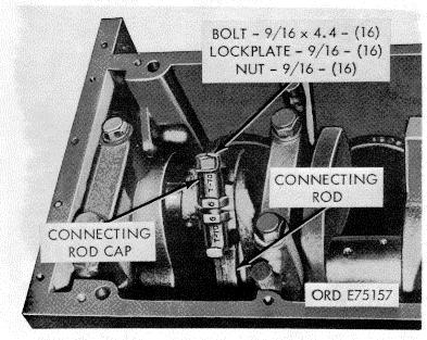
 Straighten tangs of lockplates on two bolts and nuts securing")

27 Figure Flywheel-removal/installation. (1) Remove carbon and wear ridges at of cylinder to facilitate piston removal. (2) Straighten tangs of lockplates on two bolts and nuts securing rod to crankshaft. (3) Remove nuts and lockplates. Discard lockplates. (4) Using a rubber mallet or brass driver, tap rod bearing cap to free cap from crankshaft Figure Crankshaft adapter-removal/installation. 2-12
 Tape upper bearing half shell to rod. (8) Assemble cap on rod and tag to identify assembly with cylinder. p. Crankshaft and Main Bearings (fig.")
 Using a small pry bar, loosen and remove the bearing cap and bearing half shell. Mark half shells to identify with mating cap.")

 Remove upper bearing half shells and tag on removal with mating bearing cap identification. (7) Remove rear bearing upper thrust halfrings. Figure 2-24.")
28 Figure Flywheel housing - removal/installation. (5) Tape bearing half shell to cap as re. moved. (6) Using a wooden stick, or hammer handle. push piston up out cf cylinder. (7) Tape upper bearing half shell to rod. (8) Assemble cap on rod and tag to identify assembly with cylinder. p. Crankshaft and Main Bearings (fig. 2-29). (1) Remove 19 main bearing side locking bolts and plain washers. (2) Remove 10 main bearing cap screws and, plain washers securing caps to block. (3) Using a small pry bar, loosen and remove the bearing cap and bearing half shell. Mark half shells to identify with mating cap. (4) Remove rear bearing thrust half rings. CAUTION Insure that lifter hooks are rubber covered or otherwise prepared to prevent metal-to-metal contact with shaft throws. (5) Using an overhead chain fall, or other suitable lifting device, attach a double hook lifter to two shaft throws and remove crankshaft from block. (6) Remove upper bearing half shells and tag on removal with mating bearing cap identification. (7) Remove rear bearing upper thrust halfrings. Figure Camshaft, gear and spacer plateremoval/installation. Figure Oil pan-removal/installation. and remove cap and shaft. bearing half from crank 2-13 Figure Oil pump assembly-removal/installation.


29 Figure Front cover-removal/installation. Figure Connecting rod and piston assemblyremoval/installation. Figure Crankshaft and main bearings-removal/installation. 2-14


30 CHAPTER 3 REPAIR INSTRUCTIONS Section I. General 3-1. Procedures a. The repair instructions contained in chapter cover the disassembly, cleaning, inspection, repair, test, adjustment, and assembly components and component assemblies. b. The procedures also provide for the installation of repaired components that permits a logical order of engine reassembly. c. The instructions covering cleaning, inspection, and repair are in addition to the general maintenance requirements of Chapter 2. d. Standard parts kits used in repair are described in Appendix B. Section II. Repair of Cylinder Block 3-2. Disassembly a. Pipe Plugs. Remove all pipe plugs from and water passages. b. Camshaft Bushings (fig. 3-1). Figure 3-1. Camshaft bushing removal. Remove camshaft bushings only if inspection (para. 3-4) indicates need for replacement. Using camshaft driver and mandrel (7 and fig. B-28), remove and discard bushing(s). Using camshaft driver and mandrel (7 and 8, fig.b-28), remove and discard bushing. c. Cylinder Sleeves (fig. 3-2). Remove cylinder sleeves only if inspection (para. 3-4) indicates need of replacement. 3-1 Figure 3-2. Cylinder sleeve removal Using cylinder sleeve puller and plate (10 and 11, fig. B- 28) remove and discard sleeve(s) Cleaning Clean block in accordance with paragraph 2-5. Clean all water and oil passages with compressed air Inspection a. Camshaft Bushings. (1) Visually inspect the five bushings in accordance with paragraph 2-6. (2) Check the ID of the bushings against limits specified in repair and rebuild standards (para ). Replace any bushing worn beyond specified limits. Refer to paragraph 3-2.b. for bushing removal. b. Cylinder Sleeves. (1) Visually inspect each sleeve for cracks and scratches. Replace sleeve if cracks or heavy scratches are present.
 Discard preformed packings and crevice seals. (4) Using block gage (24, fig.")
31 (2) Check ID of the sleeve against limits specified in repair and rebuild standards (para 3-179). Measurements shall be made at middle, and skirt of sleeve. Replace any s worn beyond specified limits. Refer to paragraph 3-2.c. for sleeve removal. If any sleeve requires removal perform steps 3 and 4 below. (3) Discard preformed packings and crevice seals. (4) Using block gage (24, fig. B28) cylinder counterbore and bore against limits specified in repair and rebuild standards (13-175). Replace block if measurements are beyond specified limits. c. Main Bearing Bore (fig. 33). (1) Install and tighten bearing caps. Refer to paragraph 3-186, for cap screw torque specifications. (2) Check bearing bores horizontally, vertically, and diagonally against limits specific repair and rebuild standards (para ). (3) Check alignment of bore using bearing bore alignment checking bar (19, fig. B-28) Inspect bar for run-out and OD prior to use. Bar must be inch OD and straight within in full length. Bar must pass through all bores and turn freely. Replace any cap that prevents free passage and turning. d. Tappet Bores. Check valve and injector pet bores against limits specified in repair rebuild standards (para ). e. Block Mating Surfaces. Check top machined surfaces of block with straight edge and feeler gage. If warped, distorted or uneven replace block. f. Expansion Plugs. Inspect all expansion plugs for evidence of coolant leakage. Replace all plugs that are defective. g. Miscellaneous Parts. Inspect main bearing cap screws, washers, and all pipe plugs. Check for damaged threads, nicks, burs, and other unserviceable conditions. Replace all unserviceable parts Repair Repair of the cylinder block is limited to general procedures as outlined in paragraph 2-7. Any defect, or measurement outside the tolerances listed in paragraph 3-175, is cause for replacement of block. 36. Assembly a. Camshaft Bushings. Refer to paragraph 3 2.b., and reverse the order of removal. b. Pipe Plugs. Install all pipe plugs. Refer to paragraph 3-186, for plug torque specifications. Use sealing tape or lead solder to prevent leakage. c. Cylinder Sleeves. Before installing sleeves insure that each sleeve protrusion is to inch. (1) Install crevice seal ring on machined surface above packing ring grooves, as shown in figure 3-4, with green stripe color code showing. (2) Lubricate packing rings with light coating of OE-10 lubricant. (3) Roll each ring into grooves (fig. 3-4) and straighten using ring mold mark as a guide. Figure 3-3. Main bearing bore alignment check Figure 3-4. Cylinder sleeve sells installation 3-2
32 (4) Lubricate machined packing ring bore of block with light coat of OE-10 lubricant. (5) Start sleeve into bore by hand. (6) Use a sleeve driver (31, fig. B-28) place sleeve in block. (7) Using a dial bore gage check sleeve against limits specified in repair and rebuild standards (para ). If specified limits are exceeded remove sleeve and check for possible Section III. twisted seal rings, cocked crevice seal or sleeve to block contact which could cause distortion of sleeve. If no apparent cause is evident replace sleeve. (8) Install sleeve and check sleeve protrusion using gage block (24, fig. B-28) to determine if protrusion is uniform Disassembly a. Attach a gear puller to shaft gear. b. Using a heating torch head gear hub degrees Fahrenheit. c. Apply 75 to 100 foot pounds torque on puller screw and remove gear and key. d. Remove all pipe plugs Cleaning Clean crankshaft and gear in accordance with paragraph Inspection a. Visually inspect shaft journals for the lowing defects. Replace shaft if all or any defect is present: (1) Deep nicks, grooves, scratches, evidence of galling or scuffing. (2) Burned areas, if color is a very do blue. (3) Heavy discoloration throughout shaft from over-all heating. b. Measure all bearing surfaces with a micrometer (fig. 3-5). Check against wear limits specified in repair and rebuild standards (para 3-174). c. Check shaft for out-of-round condition. Shaft must be reground or replaced if main beings or journals are worn out-of-round more than inch. d. Visually inspect thrust flange at rear main bearing. If surface is scored or scratched, flange must be reground. e. Measure flange wear (P, fig. 3-5). If flange wear does not exceed inch at any one point, flange condition is acceptable. If wear is inch or more, flange must be reground to restore flatness Repair a. Regrinding Main Bearing and Rod Journal If outof-round or worn beyond repair and rebuild standards specified limits, (para ) main bearing and rod journals may be ground undersize. Undersize grinding shall be to a limit of inch. If one bearing or journal requires grinding, all bearings or journals shall be ground to the same undersize dimension. b. Regrinding Rear Main Bearing Thrust Flange. Flange shall be reground to restore flatness to accept either standard or oversize thrust rings. If total wear and regrinding does not exceed inch, standard thrust rings may be used. Maximum regrinding for oversize rings shall not exceed inch undersize. c. Minor Defects. Minor defects on journal and bearing surfaces may be repaired by polishing with a crocus cloth dipped in dry-cleaning solvent or mineral spirits paint thinner. d. Repair Inspection. Shaft must be inspected by the electro magna-flux method for fractures after refinishing. If any evidence of cracks are noted, replace shaft Assembly a. Install all pipe plugs using sealing tape or lead sealer to prevent leakage. Refer to para-graph 3-186, for pipe plug torque specifications. b. Install key in shaft keyway. c. Oil shaft with OE-10 lubricant. CAUTION When using heating torch keep flame away from direct contact with gear teeth. d. Heat gear in oven, or with heating torch, to approximately 400 degrees Fahrenheit. e. Using rubber mallet, or brass head driver, drive gear on shaft. 3-3
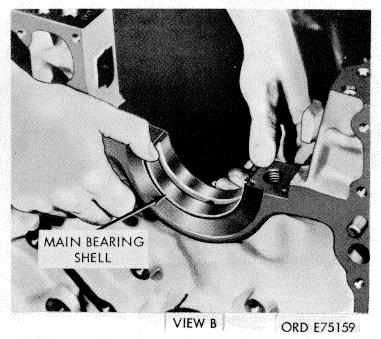
33 Figure 3-5. Crankshaft dimensions Installation a. Lay upper main bearing shells in block engaging shell tang in recess. Refer to paragraph 2-ll.p. (6) and (7). b. Coat shells with GAA. c. Install shaft in block. Refer to paragraph 2-11.p. (5) for installation instructions. d. Install upper thrust half-rings in rear main bearing with grooved side next to shaft flange. e. Coat lower bearing shells with GAA and snap into position in bearing caps. f, Install lower main bearing thrust half-rings over dowels in bearing cap. g. Install bearing caps over shaft. Main bearing caps are not interchangeable, insure that numbers stamped on caps correspond with numbers stamped on block. h. Lubricate threads of the bearing cap bolts with OE-10 lubricant. i. Install bolts and plain washers in each cap and engage threads by hand. j. Tighten bolts as follows: (1) Alternately torque both bolts in each cap to ft. lbs. (2) Alternately torque both bolts in each cap to ft. lbs. (3) Fully loosen all bolts to relieve tension. (4) Alternately torque both bolts in each cap to ft. lbs. (5) Alternately torque both bolts in each cap to ft lbs. (6) Scribe each cap in line with a corner hex of each bolt head. (7) Advance each bolt 60 degrees alternately on each cap in 30 degree increments. k. Check shaft clearance against limits specified in repair and rebuild standards (para ) as follows: (1) Using a suitable holder attach a dial indicator to rear of block (fig. 3-6) with gage plunger resting against flange face. (2) Using a pry bar move shaft to front of block. (3) Set gage to zero. (4) Move shaft to front of block and observe gage reading. If clearance, with a new shaft and thrust rings, is less than inch loosen all bearing cap bolts and move shaft to front of block then to rear of block. Refer to paragraph 3-12.j., and 3-4
. m. Coat threads of bearing cap side bolts v OE-10 lubricant.")

34 tighten cap bolts. Recheck end clearance. If the original shaft and thrust rings are installed and end clearance exceeds the wear limits the thrust rings must be replaced. l. Check clearance between main bearing caps and block at side bolt contact area on each of cap; clearance must be inch fig. 3-7). m. Coat threads of bearing cap side bolts v OE-10 lubricant. n install bolts and flat washers engage threads by hand. o. Refer to figure 3-8 for bolt tightening sequence. Torque each bolt to foot-pounds footpounds increments. Figure 3-7. Bearing cap to block clearance check. Figure 3-6. Crankshaft end clearance check. Figure 3-8. Side bolt tightening sequence. Section IV. Repair of Connecting Rod and Piston Assembly Disassembly a. Remove piston pin snap rings. b. Heat pistons in hot water for several minutes to facilitate pin removal. Push pin from piston with thumb pressure. c. Using a suitable ring expander remove piston rings (fig. 3-9). Maintain each rod and piston assembly as a group. Do not mix with other assemblies Cleaning Refer to paragraph 25 for cleaning instructions Inspection a. Inspect rod visually for nicks, notches gashes ; depressions with a 1/16-inch radius or less are not acceptable on the edge of the I beam section or on the periphery of the forging. Nicks, notches, or gashes 1/32-inch or less in depth may be removed by grinding and blending to the original contour within a minimum distance of ½ inch on either side of the defect. b. Assemble cap to rod and tighten down bolt nuts to proper torque (para ). c. Check crankpin bore with inside micrometers. The bore must be within limits shown in paragraph Out-of-round limits should not exceed inch. d. Using a dial bore gage, check crankpin bore for out-of-round condition. Out-of-round limits must not exceed inch. e. Using inside micrometers, check piston pin bushing diameter. Piston pin bushing bore must 3-5
 in rod checking fixture (40, fig. B-28).")
35 Figure 3-9. Piston and ring assembly. not exceed wear limits shown in repair an build standards in paragraph f. Check connecting rod piston pin and bearing bore alignment, rod twist, and rod centerline (fig. 3-10) in rod checking fixture (40, fig. B-28). Calibrate fixture, before checking rod, as foil (1) Select a new rod that has been checked for correct absolute length. (Production rods vary from 8.192/8.194 inches in length.) (2) Assemble cap to rod and tighten nuts to proper torque (para ). (3) Insert mandrel (22, fig. B-28) without bushing or (21, fig. B-28) used bushing into piston pin bushing bore. (4) Insert mandrel (20, fig. B-28) crankpin bushing bore. Tighten mandrel in to snug fit. (5) Position rod with mandrels installed into fixture (40, fig. B-28). (6) Move dial holders so dial pins seat on piston pin bore mandrel. Turn dial indicator gages back to zero indication. (7) Remove rod with mandrels installed from fixture, rotate rod 180 degrees and reinstall in fixture with connecting rod mandrel at top. (8) Turn dial indicator adjusting screws until dial pins seat on connecting rod mandrels. Note reading of dial indicators. Divide reading in half and adjust each dial indicator gage accordingly. (9) Remove mandrels from connecting bores. g. Check rod alignment as follows: Measurements taken directly from dial indicator indicate comparative length and misalignment of bores. (1) Install connecting rod mandrel (20,fig. Figure Connecting rod check. B28) into connecting rod bore. Tighten mandrel to snug fit. (2) Install mandrel (22, fig. B-28) used without bushing or (21, fig. B-28) used with bushing into piston pin bushing bore. (3) Install rod with mandrels in fixture Note reading, rotate rod 180 degrees, and note reading again. Total cumulative readings of each dial on fixture must not exceed inch with piston pin bushing installed or inch with-out piston pin bushing installed. h. Check rod twist with a feeler gage between piston pin mandrel and dial holding plate. Twist must not exceed inch with bushing installed or inch without bushing. i. Check rod centerline as follows: (1) Attach dial indicator gage to fixture (fig. 3-10) so that it will contact the milled surface of piston pin end of rod. (2) Slide crankpin end of rod sideways to contact checking fixture on same side that dial indicator is mounted. (3) Adjust indicator gage to zero reading. Turn Rod 180 degrees and repeat step (2) above. Dial indicator reading must not exceed inch. j. Check connecting rod bolts, bolt holes, and bolt pads as follows: (1) Bolt head must rest squarely on milled surfaces of rod. (2) With rod bolt in connecting rod and cap, measure bolt length without torque applied, then measure bolt length with it torqued to 105/115 ft lbs. If bolt length increases over inch it must be discarded. (3) Discard all bolts and nuts that have distorted threads. (4) Check bolt hole diameter, if it exceeds inch, discard rod. 3-6


36 (5) Check bolt pad corner radius ( inch). If radius does not check to tolerance, machine to proper dimensions. k. Inspect connecting rod bearing caps using ball point micrometer, dial indicator thickness gage, or Comparator. Refer to paragraph 3-177, for shell thickness and allowable wear. l. Inspect pistons for scoring, burning, or damaged ring grooves and cracks inside piston struts. A badly scored piston must be replaced; a slightly scored piston may be cleaned and reused. m. Inspect top of piston for burned spots indications of over-heating such as carbon formation on underside of the piston. Replace burned pistons. n. Using ring groove wear gage (52, fig. 28) check groove wear as follows: (fig. 3-11) (1) Insert ring groove wear gage (52, fig. B- 28) into each of the top and second ring grooves. (2) If shoulders of gage touch ring grooves lands, piston must be discarded. Figure Piston ring gap check. Measurement should be taken at ambient air temperature of 70/90 degrees Fahrenheit. q. Using inside micrometer, measure piston pin bore; discard piston if bore exceeds inch. Figure Ring groove wear check. o. Check ring gap as follows: (1) Insert each compression ring into worn portion of cylinder liner, seating it squarely using a piston head (fig. 3-12). (2) Measure ring gap with feeler gage. The allowable ring gap is 0.013/0.0230: Rings exceeding this limit should be discarded. (3) If necessary, file ring ends to obtain gap of / inch. p. Measure piston skirt diameter with micrometer at right angle to piston pin bore. Refer to paragraph 3-178, for wear limits. If piston wear exceeds inch discard piston Repair Repair of the connecting rod and piston assembly is limited to general procedures as outlined in paragraph 2-7. Any defect, or measurement outside the tolerances listed in repair and rebuild standards (paras , and 3-178) is cause for replacement. If piston pin bushings must be replaced use bushing driver (46, fig. B-28) for bushing removal and replacement. Check with plug gage (50, fig. B-28) Assembly Assemble rod to piston in reverse order of paragraph When installing rings insure the word "Top" inscribed on the ring, is to the top of the piston Installation a. Lubricate rod and piston assembly with OE- 10 lubricant. b. Compress piston rings with suitable cylindrical ring compressor. c. Remove connecting rod cap from bolts and make certain bolt heads are seated squarely on rod shoulder. These parts are not interchangeable (fig. 3-26). 3-7

37 If new rods are used, be sure caps and rods have number stamped on them before caps are removed. Caps are not interchangeable. d. Rotate engine to a vertical position on the engine stand. Rotate crankshaft to position crank throw for cylinder being assembled at bottom center. CAUTION Ring breakage will result from improper use of ring compressor. If band type compressor is used, make certain inner band does not slip down and bend piston. e. With ring compressor in place, insert piston and rod assembly in the cylinder. Position numbered side of rod toward outside of block. CAUTION Pistons are marked to indicate which side is to be assembled to "Out" exhaust side. f. Push piston assembly through ring compressor until rings seat in cylinder sleeve. g. Moving to bottom of block, grasp piston and rod assembly by rod bolts and pull down to rod journal. Leave piston assembly a short distance from actual seating. h. Coat rod bearing shell with GAA next to the crankshaft. i. Roll rod bearing shell into rod. Shell locking tang must fit in milled recess. j. Coat lower shell crankshaft bore with hit pressure grease, and seat in rod cap. k. Position rod cap over bolts that numbered side of cap mates with numbered side of rod. l. Lubricate bolt and nut threads and lock plates with clean OE-10 lubricating oil. Install lockplate and nuts to bolts, tighten nuts as outlined below. (1) Tighten both nuts 55 to 66 foot-pounds torque. (2) Tighten both nuts 105 to 115 foot pounds torque. Section V. Repair of Front Cover (3) Loosen both nuts completely to remove all tension. (4) Tighten both nuts to 30 to 32 foot- pounds torque. (5) Tighten both nuts to 60 to 65 foot-pounds torque. (6) Advance both nuts to 60 degrees in 30 degrees increments. m. Follow steps a through I above, install piston and rod assembly opposite one just installed. Secure rod to same crankshaft journal. Chamfered side of rod faces respective crankshaft cheeks and square sides face each other. n. Check rod for freedom of movement and clearance. (1) Use hand pressure to move rod side-ways. Tap lightly with soft hammer if necessary. (2) If rod is not free, loosen cap and check for dirt or burs. Secure cap as described above. (3)Push rods apart. Check for to inch clearance between rods with feeler gage (fig. 3-13). o. Bend tangs on lockplates (fig. 3-13), to locknuts. Figure Rod side clearance check Disassembly Using the front crankshaft oil seal driver (38, fig. B-28) and suitable arbor press remove oil seal as shown in figure Cleaning Refer to paragraph 2-5 for cleaning instruction Inspection Refer to paragraph 2-6 for inspection procedures. Dowel replacement is not authorized. If dowels are bent or damaged replace the cover.


 and arbox press for pressing operation. Figure 3-16. Front cover to block alinement check. Section VI. Repair of Oil Pump Assembly 3-24. Disassembly a.")
38 TM Repair No repair procedures beyond those specified paragraph 2-7 are authorized Installation a. Position front cover with new gasket to block Secure snugly with lockwashers and capscrews. b. Place dial indicator gage on crankshaft with dial pointer inside front cover bore. Rotate crankshaft and check total indicator reading. Run-out must not exceed inch (fig. 3-15). e. Install cover and secure with lockwashers and capscrews. Tighten capscrews to 30 to 35 foot-pounds torque. Figure Front cover bore alinement check Figure Crankshaft oil seal-removal/installation. c. Check that the bottom of the front cover and cylinder block are level with a straight edge. There must be no variation (fig. 3-16). d. Remove front cover and press in new oil seal (3-14). (1) Position seal with open lip to inside. (2) Use oil seal driver (38, fig. B-28) and arbox press for pressing operation. Figure Front cover to block alinement check. Section VI. Repair of Oil Pump Assembly Disassembly a. Remove two capscrews and lockplates (11 and fig. B-9) securing suction tube to pump. b. Remove four capscrews and lockplates (11 19, fig. B-9) securing scavenger tube to pump Discard gasket (17). c. Remove three capscrews and lockplates (11 and 12, fig. B-9) securing suction tube to pump. Discard gasket (21). d. Remove four capscrews. (15, fig. B-10) securing cover plate (16) to pump cover (20). Remove plate e. Remove four capscrews and lockplates (18 and 19, fig. B-10) securing pump cover to oil pump body (9). Tap cover with soft head hammer to remove from 3-9 dowels in pump body. Discard gasket (3). f. Remove six capscrews and lockplates (32 and 33, fig. B-10) securing scavenger pump body (2) to oil pump body. Tap scavenger pump body to remove from dowels in oil pump body. Gears and shafts will be removed from the pumps only in inspection warrants. g. Remove idler gear (31, fig. B-10) from shaft (30) in scavenger pump body. h. Using a suitable puller; pull drive gear (17, fig.b- 10) from cover.

39 C2, TM i. Remove pressure regulator cap (28, fig. B-10 lockplate (27), spring (26), plunger (29) and shim (25) from bore Cleaning Clean all components in accordance with instructions contained in paragraph Inspection a. Refer to general inspection procedures paragraph 2-6. b. Inspect pump drive gear. Replace pump if teeth are chipped, cracked, scored or worn smaller than inches outside diameter. c. Inspect drive shaft, replace pump if shafts scored or worn smaller than inch outs diameter. d. Inspect idler shafts, replace pump if shafts are scored or worn smaller than inch outside diameter. e. Inspect all bushings for distortion and wear replace pump if bushings are worn larger than.8750 inch inside diameter. f. Check gear pockets. If finished surfaces are damaged or pocket inside diameter is worn larger than inches or if depth is worn deeper than inches, replace pump. g. Inspect pressure regulator valve, replace if damaged. Check for burs or scratches on slide plunger Repair No repair procedures beyond those specified in paragraph 2-7 are authorized Assembly (fig. B-10) a. Press idler shaft (30) into scavenger body (2) until shaft protrudes 1.935/1.965 inches from bottom surface to pocket. b. Position idler gear (31) on scavenger idler shaft c. Press lubricating oil pump driven gear (6) with drill oil hole on main shaft (7) until shaft protrudes 0.590/0.620 inch through gear. Insert shaft through pump body (9). d. Press scavenger pump driven gear (6) on main shaft and maintain 0.002/0.004 inch clearance between gear and body. e. Press lubricating oil pump drive gear (6) on drive shaft until drive end of shaft protrudes through gear 1.455/1.485 inches. Insert long end of shaft. f. With convex (numbered) side of pump drive gear (17) up, press gear onto shaft until shaft protrudes 0.185/0.215 inch through drive gear. g. With new gasket (3) over dowels in pump body, position scavenger body to lubricating oil pump body, engaging pump gears. Secure with lockplates and capscrews (32 and 33), lock capscrews in plate with lock tangs. h. With new gasket (13) over dowels, position pump cover (20) to lubricating oil pump body, engaging pump gears; secure with lockplates and capscrews (18 and 19). Lock capscrews in place with lock tangs. i. With dial indicator, check for / inch clearance of pump drive shaft. j. Position cover plate (16) on cover body secure with socket head capscrews (15). Center punch around screw heads to lock in cover. k. Position pressure regulator plunger, shim and spring (25, 26 and 29) in pump body, secure with cap and lockplate (27 and 28). l. Lubricate pump body freely with lubricating oil, OE-10, drain oil, and cover openings with tape to prevent entry of foreign material. m. Install tube assemblies (suction and aerator) on lubricating oil pump to permit installation of complete unit during engine assembly. Reverse steps a., b., and c., paragraph installation a. Refer to paragraph 2-llm, and reverse removal procedures to install pump. b. Check pump drive gear backlash as follows: (1) Attach dial indicator to block, place indicator arm on gear teeth as shown in figure (2) Rotate gear by hand to advance position and set indicator at zero. Back gear to retard position and note indicator reading. Check indicator reading against specified limits in repair and rebuild standards (para ). If reading is outside limits specified pump gear train must be replaced Figure Drive gear backlash check.


40 Section VII. Repair of Camshaft Disassembly Remove camshaft gear only if thrust plate or gear is chipped, cracked or visibly worn. If necessary to facilitate removal, heat gear to 400 degrees F. a. Place shaft in a suitable press between blocks and press off gear. b. Remove key and thrust plate. Discard key Cleaning Clean camshaft and components in accordance with instructions contained in paragraph Inspection a. Check shaft journals and injector lobes against specified limits in repair and rebuild standards paragraph Replace shaft if any measurement is outside limits specified. b. Check thrust plate against specified limits in repair and rebuild standards, replace plate if limits are exceeded. c. Visibly inspect gear in accordance with general inspection procedures, paragraph 2-6 d. Check gear diameter against specified limits in repair and rebuild standards paragraph Replace gear if limits specified are exceeded Assembly a. Install key in place, red tip to rear of camshaft. b. Coat camshaft thrust bearing with lubricating oil OE10 and place thrust bearing on camshaft. c. Coat gear hub area on camshaft with lubricating oil OE-10. d. Heat gear to 400 degrees Fahrenheit in oven or with heating torch and press gear onto shaft CAUTION When using heating torch, heat gear hub only. Do not direct flame at gear teeth. TM e. Check camshaft and clearance as follows: (1) With a suitable holder attach a dial indicator to the block, as shown in figure 3-18, with indicator arm resting on face of gear teeth. (2) Push and pull on shaft several times. (3) Push shaft in until shaft bottoms and set indicator to zero. (4) Pull out oil shaft and note reading on indicator. (5) Check reading against specified limits in repair and rebuild standards (para ). If end clearance is not within limits specified remove camshaft and replace thrust plate. f. Attach dial indicator as shown in figure 3-19 and measure gear backlash against limits specified in repair and rebuild standards (para ). If backlash is not within specified limits replace camshaft gear. Figure Camshaft end play check Repair Repair of camshaft and gear is limited to general procedures outlined in paragraph Installation a. Lubricate lobes and journals with high pressure grease. b. Install camshaft in the block (fig. 2-24). c. Index "0" mark on camshaft gear with O mark on crankshaft gear to insure correct timing. d. Secure camshaft thrust plate to block with lockplates and capscrews. Figure Crankshaft gear backlash check. 3-11
41 TM Cleaning Section VIII. Repair of Crankshaft Adapter Refer to paragraph 2-5 for cleaning instruction Inspection Inspect adapter in accordance with instruction in paragraph Repair No repair procedures beyond those specified in paragraph 2-7 are authorized for this part Installation a. Refer to paragraph 2-1ll.i., and reverse procedures to install adapter. b. Tighten capscrews in the sequence as shown in figure Figure Crankshaft adapter tightening sequence Section IX. Repair of Flywheel Housing and Spacer Plate Disassembly (fig. B4) a. Using suitable arbor press remove oil seal (8). b. Remove pipe plugs (6 and 17) Cleaning Clean housing and spacer plate in accordance with instructions contained in paragraph Inspection Inspect housing and spacer plate in accordance with instructions in paragraph Repair No repair procedures beyond those specified in paragraph 2-7 are authorized for these units Assembly a. Using a suitable arbor press, and with housing properly supported to prevent distortion install oil seal. b. Install pipe plugs Installation (fig. B-4). a. Install gasket (3) on block. b. Install spacer plate (2) and gasket (1). c. Install housing. Refer to paragraph 2-11 and snug tighten capscrews. If a replacement housing is to be installed replace dowels only if the housing will not line up within bore tolerance. d. Install dial gage and holder (34, fig. B-28) as shown in figure 321, and check crankshaft flange concentricity as follows: (1) Place chalk marks at position A, A, B, and B as shown in (fig. 3-21). (2) Check reading at B and B. Total runout is not to exceed inch. (3) Check reading at A and A. Total runout is not to exceed inch. (4) If flywheel housing bore is not within limits, move as necessary to correct measurements. CAUTION Oil seal bore run-out must also remain within limit of inch. e. If both bores cannot be brought within limits, the flywheel housing must be replaced. f. After measurements are brought within limits, tighten capscrews alternately and evenly; make final check after tightening. Tighten capscrews to 35 ft. lbs. torque. g. Check flywheel housing face as follows. (1) Move dial gage-(fig. 3-21) and attachment to housing face. (2) Using a pinch bar wedged between a main bearing cap and crankshaft throw, take up crankshaft end clearance. 3-12
 Total flywheel housing face run-out must not exceed 0.008 inch. (5) If necessary, to correct housing face run-out, after the bore has been alined, remove housing and recheck mating surfaces.")
42 TM (3) Turn crankshaft and check at points A, A, B, and B housing face (fig. 3-21). Take up crankshaft end clearance in the same direction each time a measurement is taken. (4) Total flywheel housing face run-out must not exceed inch. (5) If necessary, to correct housing face run-out, after the bore has been alined, remove housing and recheck mating surfaces. Then install housing on housing dowels and install capscrews. Tighten capscrews to 35 foot-pounds torque. Section X. Repair of Oil Pan Figure Flywheel housing concentricity check Disassembly Remove drain and pipe plugs Cleaning Clean oil pan in accordance with instructions contained in paragraph Inspection Inspect pan and plugs in accordance with instructions contained in paragraph Repair a. Repair damaged threaded holes by tapping. Refer to paragraph 2-7 for instructions. b. Repair small cracks by welding. Refer to paragraph 2-7 for welding instructions Installation (fig. B-9). a. Shellac new single-piece gasket (9) to pan. b. Aline pan to block and install 12 capscrews, lockwashers, and flat washers (25, 3, and 24), finger tighten capscrews. c. Reach inside inspection opening on right side of pan and install two capscrews and lockwashers (10 and 11) securing suction and scavenger tubes (13 and 20) to sump. d. Shellac new single-piece gasket (7) to inspection plate (6). e. Install plate with six capscrews and lockwashers (5 and 3). f. Aline oil pan to flywheel housing and install two capscrews (12), lockwashers (3) and flat washers (24), finger tighten. Install six capscrews, lockwashers, and flat washers (16, 10, and 9. fig. B-4). Tighten all oil pan securing capscrews. CAUTION Do not weld finished surfaces Assembly Install all pipe plugs and drain plugs Disassembly Using blunt chisel and mallet drive the ring gear from the flywheel. Apply pressure, during removal, at various positions around ring gear to prevent distortion Cleaning Clean flywheel and ring gear in accordance with instructions contained in paragraph 2-5. Section XI. Repair of Flywheel Inspection Inspect flywheel and ring gear in accordance with instructions contained in paragraph Repair No repair procedures beyond those specified in paragraph 2-7 are authorized for flywheel or ring gear.
43 TM Assembly Assemble flywheel and ring gear as follows: a. If an oven with a heat control is not available, heat gear with heating torch, (not a cutting torch) from inside diameter so heat travels outward towards the teeth. b. Use a Tempilstick crayon or equivalent to determine amount of heat applied. Stroke gear with 600 degrees Fahrenheit crayon. At 600 degrees Fahrenheit the crayon will leave a liquid smear. Crankshaft end clearance must be kept to rear limit while the above check is made. (7) Tighten flywheel capscrews to a final 200 to 205 footpounds torque in 50 foot-pound increments in sequence shown in figure Secure flywheel capscrews with locking wire. CAUTION Overheating gear to temperatures above 600 degrees Fahrenheit will soften gear metal. c. Place the ring gear on flywheel and quickly drive onto flywheel until gear is firmly seated Installation a. Install two 5/8-18x6 inches long, guide headless studs in crankshaft flange. b. Position flywheel over guide studs. c. Insert eight flywheel capscrews, and tighten alternately to 50 to 60 foot-pounds torque in sequence shown in figure Tighten flywheel capscrews to final torque of 200/205 foot-pounds. d. Check flywheel bore and clutch face as follows: (1) Attach indicator and check pilot bearing bore and drive ring pilot bore. Total run-out must not exceed inch. (2) Shift gage to indicate clutch mounting face. (3) Chalk four marks equidistant on flywheel circumference (fig. 3-23). (4) Turn crankshaft, taking up crankshaft end clearance as chalk marks aline with indicator Run-out must not exceed inch. (5) If run-out exceeds inch, remove flywheel and clean flywheel and crankshaft mating surfaces. (6) Again install flywheel and recheck bore and face. : USE LOCKWIRE AS REQUIRED AT Figure Flywheel tightening sequence. A-BORE.004 INCH (RUN OUT) B-CLUTCH MOUNTING FACE.005 INCH (WOBBLE) Disassembly (fig. B-6). a. Remove and discard spring clips (31 and 35) from tappet body (25 and 33). b. Place inch shim between body side of roller (27 and 29) to prevent sprit back when removing roller. Press on end of pin Section XII. Repair of Valve and Injector Tapplets 3-14 (26 and 32) that is not secured by lockwire to remove pin. c. Discard pin and lockwire. d. Press bearing sleeve (27) or injector roller (29) from injector tappet Cleaning Clean tappets in accordance with instructions contained in paragraph 2-5.

44 TM Inspection a. Perform inspection in accordance with the instructions contained in paragraph 26. b. Check for scored, flaked, or chipped rollers on bearing sleeves. Discard damaged parts. If any of the above conditions exist, camshaft should be inspected very closely for damage. c. Measure tappet body outside diameter for wear. Measure roller and bearing sleeves od and id for wear. Discard if worn beyond limits contained in repair and rebuild standards paragraph d. Check tappet sockets by "bluing" corresponding new push rod on ball end and rotating in tappet. A full seat should be indicated. e. Check body pin holes and inspect hole for burrs before reassembly Repair No repair procedures beyond those specified in paragraph 2-7 are authorized for tappets Assembly a. Press new injector roller on bearing sleeve in tappet until securely seated. e. Using dial indicator gage (calibrated in tenths of a thousandth inch) check concentricity of rotating roller. CAUTION Injector and valve tappet dimensions are not alike. Use correct dimensions when checking wear. Roller eccentricity of the injector tappet cannot exceed inch, the valve tapped cannot exceed inch. Move indicator to a new location and recheck. f. Using same indicator check squareness of roller by sweeping indicator across diameter or end of roller, then sweeping the other end. Rotate tappet roller 180 degrees and check again at roller ends by sweeping across the diameter. Roller squareness must not exceed inch in either injector or valve tappet assemblies. It is recommended to extend some downward pressure against the roller when gaging to assure firm contact. Assemblies that do not pass the inspections above must be disassembled, (perform inspection during disassembly to determine the cause for rejection) reassembled, and reinspected. CAUTION Lubricating oil passage in pin must be alined for proper lubrication. b. Insert inch shim between side of roller or sleeve and tappet fork. Press pin through body and roller with lockwire in pin Testing Tests of either the injector or valve tappet assemblies require a surface plate, small V block with clamp (to hold tappet in position), and dial indicator calibrated in tenths of a thousandth inch attached to a surface plate (fig. 3-24). a. With a small wire, check indexing of pins and body lubricating oil passages. b. Check freeness of roller by rotating two or three turns. If "drag" is felt, the plating on the pin has probably picked up burrs during assembly or pin is not being held securely during assembly. c. Stand small V block on surface plate. d. Stand tappet assembly on surfacing plate with roller up. Secure tappet in V block with clamp. Figure Tappet assembly test Installation a. Install new retainer spring on each tappet (31 and 35, fig. B-6). b. Install tappets in tappet bores of block, refer to paragraph 2-ll.g. Injector tappets are larger 3-15

 remove crosshead guides as shown in figure 3-28. e. Remove all pipe plugs. 3-45.")

. Inspect for loose valve seats by tapping lightly on the cylinder head near the inserts.")
45 TM and are placed between valve tappets. Aline tappet and must be inch clearance between tappet and plate lock in position with retainer plate. There when capscrew is tightened down. Section XIII. Repair of Cylinder Heads Disassembly a. Install head in holding fixture (25, fig. B-28 as shown in figure b. Using valve spring compressor (44, fig. B-28) remove valve assemblies as shown in figure c. Using injector sleeve puller (19, fig. B-28) remove injector sleeves as shown in figure d. Using cross head guide puller (43, fig. B-28) remove crosshead guides as shown in figure e. Remove all pipe plugs Cleaning Clean cylinder heads and valve assemblies in accordance with instructions in paragraph 2 Figure Injection sleeves-removal/installation. Figure Cylinder head in fixture. Figure Crosshead guide-removal/installation. Figure Valve assemblies-removal/installation Inspection Refer to paragraph 2-6 for general inspection procedures. a. Cylinder Head Fuse Plugs (fig. B-6). Cylinder heads are equipped with fuse plugs containing a metal alloy center that melts if the engine overheats. Examine all fuse plugs for evidence of overheating. Replace all defective plugs. b. Valtve Seats (fig. 3-29). Inspect for loose valve seats by tapping lightly on the cylinder head near the inserts. If valve seat is loose enough to bounce, or cannot be reground, mark for replacement, If valve seat area exceeds inch at any point, replace head assembly. c. Injector Sleeves. (1) Perform a water test as follows. 3-16
 on a scrap injector and cup assembly into each injector sleeve. Tighten sleeve holders to 10/12 foot-pounds torque or injector capscrews to 30/35 foot-pounds torque as shown in figure 3-30.")
 Open water outlet valve to check for free water circulation through cylinder head.")
46 If nylok capscrew breakaway torque is less than 15 inch pounds, replace capscrews. TM Figure Valve seat-sectional view. (a) Install injector sleeve holder (15, fig. B-28) on a scrap injector and cup assembly into each injector sleeve. Tighten sleeve holders to 10/12 foot-pounds torque or injector capscrews to 30/35 foot-pounds torque as shown in figure (b) Using water heated to 175/200 degrees Fahrenheit, test cylinder head for leaks at 35/85 pounds pressure. (c) Check carefully around injector for any evidence of water leaks. Mark sleeves for replacement that evidence leakage. If cylinder head shows leakage, replace head. (d) Open water outlet valve to check for free water circulation through cylinder head. (2) Inspect injector sleeves for scratches on cup seat area and for continuous contact by using Prussian Blue. Mark sleeve that is scratched on does not show continuous seat contact, of at least inch wide, for replacement. (3) Check injector tip protrusion by installing injector assembly and torquing to 30/35 footpounds. If injector protrusion exceeds inch mark sleeve for replacement (fig. 3-31). Figure Injector tip protrusion measurement. d. Valves. (1) Inspect valve heads for pitted, cupped, cracked, or excessively worn condition. Check valve head rim thickness (fig. 3-32) and replace valve if less than 1/16 inch. (2) Inspect valve stems for scored, cracked or excessively worn condition. If stems are worn beyond inch replace valve. (3) Inspect collet recesses (fig. 3-32) for serviceability. f. Crosshead Giudes (fig. 3-33). (1) Check crosshead guides with a square. They must be perpendicular at four right angles with the cylinder head. (2) Measure outside diameter of crosshead guides using a micrometer. Guides must measure inch minimum. Discard if worn beyond that limit. (3) Measure crosshead protrusion above block to 2.090/2.110 inches. Discard guides not within these tolerances. g. Valve Guides (fig. 3-34). (1) Adjust a small bore gage with a micrometer at inch above worn limit, and use as "No-Go" gage. (2) Mieasure the hole at several points crosswise and endwise of the head. (3) Mark valve guide for replacement if worn larger than inch inside diameter. (4) Inspect sharp edge of guides for chips, cracks and burrs. If damaged, mark for replacement. Figure Injector sleeve holder installation. 3-17
 Replace springs if load is less than indicated under \"wear limits\" at required compressed length. Figure 3-32. Valve head and collet check. Figure 3-34. Valve guide check Figure 3-33.")

 Using a spring tester capable of very accurate measurements of spring lengths and applied load, check springs against limits speciflied in repair and rebuild standards, paragraph 3-183.")
47 TM A 1/32 inch spacer may be used under valve spring when insert and valve have been refaced. (2) Replace springs if load is less than indicated under "wear limits" at required compressed length. Figure Valve head and collet check. Figure Valve guide check Figure Crosshead guide cheek. (5) Check valve guide protrusion to limit of 0.695/0.710 inch. h. Valve Springs (fig. 3-35). Weak valve springs may cause flutter which results in excessive wear on both valve and seat. Valve flutter interferes with valve timing and may cause valve to strike the piston head. Weak springs may also cause valve warping, cracking and breaking. (1) Using a spring tester capable of very accurate measurements of spring lengths and applied load, check springs against limits speciflied in repair and rebuild standards, paragraph Figure Valve spring test Repair a. Resurface Cylinder Head. Resurface head only if it has been scratched, etched, or worn unevenly at point of contact with gasket sealing areas. (1) Remove a maximum of inch of material. The gasket surface should not deviate from a true plane b, mote than inch. 3-18
 Restore counterbore and pocket depth at valves and shallow counterbore area around injector port (fig. 3-36) by grinding with a stone dressed to the indicated contours. b. Regroove Cylinder Head.")
48 TM (2) Measure head height using micrometer or vernier calipers; dimensions must not exceed / inches. (3) Restore counterbore and pocket depth at valves and shallow counterbore area around injector port (fig. 3-36) by grinding with a stone dressed to the indicated contours. b. Regroove Cylinder Head. If cylinder head has been resurfaced, regroove with grooving tool (33, fig. B- 28), as shown in figure (1) Select scrapped injector, preferably one with class "0" plunger bore and injector cup. Cut off cup to expose plunger bore, to keep cup seal area intact. (2) Install injector in cylinder head and tighten 30/35 foot-pounds torque. (3) Select correct tool spacer block, inch thick. Assemble the regrooving tool, positioning largest pilot pin so it protrudes downward in same direction as cutter; tighten assembly in place. (4) Rotate cylinder head and install regrooving cutter in injector bore (fig. 347). (5) Check position of stop in tool holder to make certain it will not contact water hole during regrooving operation. (6) Adjust regrooving cutter so it protrudes 0.006/0.008 inch below stop. Rotate tool clockwise to cut grooves. Do not rotate counterclockwise. CAUTION Do not attempt to cut deeper than cutter groove depth or grooves will not form in head. Groove lands should be 0.010/0.015 inch wide and must not extended above head surface Figure Cylinder head regrooving. Figure Valve and injector counterbore dimensions c. Grind Valves. (1) Wet grind valve from horizontal to exactly 30 degree angle. (2) Inspect rim thickness after grinding as shown in figure 332; if rim is less than 1/16 inch, valve is not suitable for use and must be replaced. (3) Check valve in reamed guide and against newly ground valve seat face. Pencil mark valve face and drop into position and rotate 10 degrees. A good seat will be indicated if all pencil marks are broken. If pencil marks are not broken either valve seat or valve refacing tools have not been properly adjusted; final check should be made with vacuum tester Assembly a. Valve Guide.
.")
 Ream crosshead guide bore to 15/82 inch if necessary after installation. c. Injector Sleeves. (1) Install injector sleeves using sleeve driver (14, fig. B-28) as shown in figure 3-40.")
 Remove injector sleeve holder.")
49 TM CAUTION Insure that the 1/16 inch hole in valve guide is turned toward exhaust manifold and that the hole remains open after assembly. (1) Install valve guides as shown in figure 338. Press in valve guide to 0.695/0.710 inch above head surface with valve guide driver (49, fig. B-28). (2) Ream valve guide from bottom side of cylinder head using reamer, drill press and floating tool holder. Valve guide must have inside diameter of / inch after reaming. (2) Ream crosshead guide bore to 15/82 inch if necessary after installation. c. Injector Sleeves. (1) Install injector sleeves using sleeve driver (14, fig. B-28) as shown in figure (2) Remove injector sleeve driver and install injector sleeve holder (fig. 3-30). (3) Using sleeve expander (13, fig. B-28), roll upper portion of injector sleeve to 1.145/1.155 inches inside diameter as shown in figure Set drill press at 250 rpm and 600 pounds pressure for 30 seconds; apply OE-10 oil during operation. (4) Remove injector sleeve holder. (5) Using sleeve roller (16, fig. B-28), roll lower portion of injector sleeve as shown in figure (6) Cut injector sleeve seat with sleeve cutter (17, fig. B-28) as shown in figure 343, to provide maximum allowable sleeve protrusion of inch, 0.100/0.115 inch nominal. Figure Valve guide installation b. Crosshead Guides. (1) Install crosshead guides as shown in figure Press in crosshead guide to 2.090/ inches above head surface with guide spacer (47, fig. B-28). Figure Injector sleeve installation. d. Valve Seat Inserts. (1) Recondition valve seat counterbore using tool kit, cutter, and valve guide (48, 51 and 41, fig. B-28) to proper size (A, fig. 3-36), as shown in figure (2) Install swirl plate in intake valve ports only as shown in figure (3) Install valve seat insert using valve seat insert tool kit and peen insert in cylinder head as shown in figure e. Grind Valve Seats. (1) Select a suitable valve grinding machine Figure Crosshead guide installation. 3-20

 If ground seat is wider than 1/8 inch maximum stock can be removed from points \"A\" and \"B\" (fig. 3-29) with specially dressed valve seat grinder stones.")
 Dress wheel for final finish and finish grind with light touches of stone against valve seat face. (5) Check valve seat concentricity with valve seat indicator.")
. 3-69. Tests a. Valve Seating (fig. 3-47).")
50 * Figure Injector sleeve rolling-upper portion. Figure Injector sleeve seat cutting. Figure Injector sleeve rolling-lower portion and proper size mandrels to fit reamed valve guides. Dress grinding stone to 30 degrees from horizontal. (2) Grind valve seats, holding motor as nearly vertical as possible. (3) Check valve seat width which should be 1/16 to ¼/ inch. (a) If ground seat is wider than 1/8 inch maximum stock can be removed from points "A" and "B" (fig. 3-29) with specially dressed valve seat grinder stones. (b) Narrowing should not extend beyond chamfer on seat insert. Chamfer provides for peen metal. (4) Dress wheel for final finish and finish grind with light touches of stone against valve seat face. (5) Check valve seat concentricity with valve seat indicator. (a) Use valve guide as a center. Gage Figure Valve seat insert counterbore. must be a perfect fit on pilot mandrel. (b) Run out should not exceed inch total indicator reading. f. Valve Assemblies. Reassemble valve assemblies in reverse order of disassembly (para. 3-64) Tests a. Valve Seating (fig. 3-47). Test valve seating for leaks with cylinder head gage (2, fig. B-29) as follows: CAUTION Never vacuum test cylinder head with injector installed. Installation of injectors could cause misalignment of valves in valve seat area and result in leakage during test. (1) Select a vacuum cup of proper size for valve to be tested. 3-21
 Operate tester with suction cup against clean glass plate. (c) Check for dirt on valve and seat. (8) If necessary regrind valve seat (para. 3-68.e.). Figure 3-45.")

. Figure 3-46.")
51 is less than "10" seconds valve seat is unsatis- factory. (7) If valve seat seal is unsatisfactory: (a) Check for leaking connections on tester. (b) Operate tester with suction cup against clean glass plate. (c) Check for dirt on valve and seat. (8) If necessary regrind valve seat (para e.). Figure Intake valve port swirl plate-installation It is possible to mistake leakage around the valve seat insert for valve seat leakage. If this is suspected, apply grease to the outside edge of the insert to make a grease seal. Perform vacuum test and insert grease seal for a "break" indicating air leakage between wall of counterbore and valve seat insert. If leak around insert is detected, correction is required before continuing with test b. Head Assembly. Perform a water test on the rebuilt head assembly (para. 366.c.). Figure Valve seat insert peening. (2) Valve and seats must be dry and clean. Place suction cup over valve head. O-Ring on cup should seat on flat surface of head surrounding valve. Grease area lightly with GAA for a better seal. (3) Turn hand shut-off valve to open position. Hold push button down to operate vacuum pump. (4) Operate vacuum pump until hand on vacuum gage stops climbing at 15/25 inches of mercury on the dial. (5) Close shut-off valve; release push button to stop pump. (6) Time vacuum pressure decrease on gage to test valve seat. (a) "Start" timing as soon as hand reaches "15" inches of mercury on dial. (b) "Stop" timing when hand reaches "12" inches of mercury on dial, if elapsed time Installation Figure Valve seat test. a. Make certain pipe plugs are installed and secure. b. Clean mating surfaces of cylinder block and cylinder heads. Make certain cylinder walls are clean and well lubricated with OE-10 engine oil. c. Place grommet retainers in water passages in block, small end up. d. Lay gasket on flat surface. Press grommets in place by hand. e. Install head gaskets over ring dowels so that 3-22
 as shown in figure 2-19, capscrews, lift head with suitable hoist and lower into place over dowels. g. Blow all liquid and dirt from cylinder head capscrew holes with compressed air.")
52 word "TOP" on gasket is visible. Be careful not to dislodge grommets as gasket is lowered over grommet retainers. f. Using cylinder head lifting plate (45, fig. B-28) as shown in figure 2-19, capscrews, lift head with suitable hoist and lower into place over dowels. g. Blow all liquid and dirt from cylinder head capscrew holes with compressed air. CAUTION Keep rust preventative oil from internal engine parts to prevent corrosive damage. h. Coat short cylinder head capscrews with rust preventive lubricant and install. sequence shown in figure Tighten each in Section XIV. Repair of Fuel Injectors General This section covers the disassembly, inspection, repair, assembly and testing of injectors (fig. 3-49). The injector is a simple mechanical unit which receives fuel from the fuel pump, under pressure, and injects it through fine injector cup spray holes into the combustion chamber. The description "PT Injectors" is only used to in the cate that the injector is used with the PT fuel systems. The PT injectors are mounted in the cylinder head and are cylindrical in shape. The V8-300 engine uses of PT type C injector. It consists of two major assemblies: injector body and plunger; and the injector cup. The orifice descriptions below are given for functional maintenance purposes. a. Adjustable Orifice Plug. The orifice plug used in the inlet drilling of the cylindrical injec- tor adjusts delivery of fuel. Fuel delivery is ad- justed by changing the orifice plug or by burnish- ing the plug in operating position. Some ori plugs have a flange and require a gasket bene the flange. b. Drain Orifice. The drilled orifice in cup E of the injector is the drain drilling. This orifice is fixed in size and must not be altered in any way. c. Metering Orifice. The orifice in cup end of the injector allows fuel to enter plunger bore and cup; do not alter in any manner Disassembly (fig. 3-49). a. Lift out injector plunger and spring. Tag mating parts. Injector bodies and plungers are class fits, do not interchange. b. Remove and discard O-Rings from injector body. c. Disassemble clamp securing screen to injector body. Do not remove adjustable orifice plug from inlet groove. d. Place injector in injector cup wrench (30, fig. B-28) and install in injector holding fixture (29, fig. B-28) as shown in figure e. Remove injector cup; note size markings on injector body for future reference. f. Remove ball retainer, ball, and gasket from top of injector body, discard gasket. g. Place injector plunger in suitable holding device with spring retainer upward. h. Pull link and retainer as an assembly. i. Using a collet type hand tap holder, pull injector links (fig. 3-51) Cleaning Clean injector components in accordance with paragraph Inspection Perform general inspection of components in accordance with wear limits in repair and rebuild standards (para ). Detailed inspection of injector components follow. 3-23
 Plunger seat pattern covers less than 40 % continuous area around cup, cone or plunger bore (fig. 3-52). Figure 3-51. Injector Link-removal/installation.")

 Corrosion damage and effect of excessive heat, usually resulting from high acid or b. Injector Body.")
 Use strong magnifying glass to check for burs, carbon, and distorted radii in orifices. When injector orifices are damaged, the injector will not function properly.")
53 sulphur content in fuel or overload operating conditions. (3) Enlarged or distorted spray holes, caused by cleaning with drills, wires, or other instruments. (4) Plunger seat pattern covers less than 40 % continuous area around cup, cone or plunger bore (fig. 3-52). Figure Injector Link-removal/installation. Figure Fuel injector PT (type C) Figure Plunger seat pattern. Figure Injector cup-removal/installation. CAUTION Never alter size of injector spray holes. a. Injector Cup. Inspect injector cup spray holes and tip with magnifying glass and compare with new cup. Discard cup if any of following conditions exist: (1) Interior/or exterior abrasive wear. (2) Corrosion damage and effect of excessive heat, usually resulting from high acid or b. Injector Body. (1) Inspect injector body plunger bore for scoring, if scores are too deep, injector body should be replaced. (2) Use strong magnifying glass to check for burs, carbon, and distorted radii in orifices. When injector orifices are damaged, the injector will not function properly. c. Injector Plunger. (1) Check closely for metal seizure caused by scuffing or scoring. (2) Spots or surface disruption at top of plunger or at mid-point, usually are normal results of rocker lever thrust action. Unless metal is displaced or wear is measureable at these points, 3-24
54 plunger may be reused. If worn excessively, place body and plunger. (3) Narrow streaks running the length plunger usually are the result of varying thick- ness of penetrate treatment used to prevent rust ing. Plunger is satisfactory for reuse unless surface distortion is evident. d. Injector Spring. (1) Check spring for excessive wear breaks. (2) Test spring tension on spring tester that is capable of very accurate measurements of spring lengths and applied load by means of standards and dial indicator gage. (3) If injector springs compress to dimensions at less than loads given in repair and re- build standards, springs must be replaced Repair Repair of the injector assembly is limited to re- placement of spare parts and general repair pro- cedures in accordance with paragraph Assembly (fig. 3-53). a. Drop check ball into bore in top of injector body. b. Using check ball seating tool (5, fig. B- 28) screw down against ball and tighten to inlb torque as shown in figure c. Install retainer plug, with a new gasket, and tighten to inch pounds. d. Lubricate new injector body O-ring with OE-30 oil. e. Using O-ring tool (39, fig. B-28), slide O- ring onto injector body as shown in figure If sealing surface of PT (type C) cup is slightly damaged, use lapping blocks and mixture of 600 grit lapping compound and OE-30 lubricant to smooth cup. Oscillate cup on block, applying light pressure. Clean thoroughly before in- stalling. f. Select plunger and body with same size markings (fig. 356), immerse injector plunger in clean injector test oil. g. Install plunger in injector body from which it was removed and place injector in fixture (fig. 3-50). h. Place new retaining ring on new plunger link and press link into place. Press retainer flush to inch below bore surface. i. Select cup of proper size (fig. 3-57) and in- stall finger tight on injector body. Apply tension to aline plunger in body, back off % turn, tighten with cup wrench (30, fig. B-28) to 55 foot- pounds as shown in figure Spring tension in tool is controlled by spacers marked by the engine model which alines plunger and cup when per- forming above operation. CAUTION If cup is replaced, always use identical replacement cup. j. Check injector assembly plunger seating on test stand as described in paragraph 3-77.a. k. Remove injector plunger from body. Lubricate plunger with test oil. Install injector spring and plunger in body. Check to see that it does not bind as it seats in cup. l. Check cup spray pattern as described in test section. If spray pattern tools are not available, fill injector body two-thirds full of clean fuel. Insert plunger forcing fuel out cup spray holes to see that they are open and clean Test and Calibration a. Injector Plunger Seat Test. (1) Install injector assembly on test stand as shown in figure Figure 3-56 illustrates the injector checking fixture currently in use in the Army supply system and is available through normal supply channels. (2) Attach 80/90 p.s.i. air supply to test stand air coupling. (3) Remove spring and plunger from the assembled injector and re-install plunger only in the injector body. (4) Place injector in test set-up with cup seated in the counterbore below the air valve. (5) Install cylindrical injectors with drain and outlet holes up. (6) Position injector plunger with size mark centered between the injector inlet and drain openings. Fill opening with fuel oil and operate plunger several times to purge any air trapped in injector. (7) Seat handle against injector plunger Oil injector cup and retainer with OE- 30 oil before assembly. 3-25


55 CAUTION Before deciding the injector is leaking, be sure any air trapped in the fuel passage has been purged, (9) If leakage exists, check for dirt or other foreign material, changing or reassembly of the cup will often correct leakage. Figure Injector check ball seating. link and let weight control force against plunger Do not apply any additional force to handle during test. (8) Turn on air pressure. Injector is acceptable if the duration of time before the first air bubble appears is more than ten seconds, and time between the observed air bubbles is not less than five seconds. 3-26
56 Figure Injector body and plunger markings. Figure Injector cup marking. 10) If the cup seat is damaged in any way and injector does not pass cup-to-plunger seat test, plunger may be lapped into cup to obtain good seating. Use no greater than 300 grade lap- ping compound mixed with OE30 lubricating oil. Applying light pressure, oscillate plunger in cup back and forth for approximately one minute. CAUTION After lapping, both the cup and plunger must be thoroughly cleaned. Lapping compound will damage fuel system unless removed. The most effective cleaning process is the use of an ultrasonic cleaner, if available, and an after rinse in fuel oil. (11) If injector is satisfactory, remove plunger. Re-install spring and plunger. b. Calibrating Injector Test Stand (fig. 3-9). The injector test stand is used to test all injec. Figure Injector plunger seat test. tors. It flow tests the complete injector assembly by measuring fuel delivery. The injector is actuated under controlled conditions closely simulating actual operating conditions. The test stand counts injection strokes, supplying fuel at specified pressure, and measures the delivery in a glass graduate. The following preliminary steps and procedures are required prior to test stand operation. CAUTION Before operating the test stand make sure that the cam box is filled to the level of the sight glass with OES-30 oil. The test stand must be located near hot and cold water connections. Water temperature, controlled by a mixing valve, is used to maintain test fuel at an 80/100 degree Fahrenheit temperature range. 3-27
57 (1) Install factory calibrated master injector gage (36, fig. B-28), in test stand to adjusting other injectors for fuel delivery. CAUTION The master injector must never be tampered with. (2) Fill hydraulic fluid reservoir. (3) Test oil tank on stand must be kept at least ye full of diesel fuel. (4) Aline timing mark (fig. 3-60) and close hydraulic valve and open the air valve (fig. 3-61). Place load cell tester (1, fig. B-29) in test stand and clamp in place by opening hydraulic valve (fig. 3-61). CAUTION Never operate test stand with load cell in position. (5) Adjust air pressure by turning knurled button on air regulator until the load cell indi cates within marked band on load cell gage (0 3-62). Lock knurled button in place with locknut. Note air gage pressure (gage at top hydraulic reservoir). (6) Remove load test gage by opening ] draulic valve and returning air valve knob center position. With cylinder rod in down posi- tion, check to make sure hydraulic fluid shows hydraulic oil lever sight bulb. (7) Open air valve. While cylinder rod is at the top of its travel, check to make sure there no air in hydraulic fluid sight glass. (8) Make sure injector seat contains 0.0 inch restrictor orifice when calibrating test stand. (9) Place injector adapter (fig. 3-63) o~ master injector and engage locators in inject mounting holes. Make sure seat is retracted a timing marks are alined at timing wheel. (10) Position test stand link (marked NV NH, H) over injector plunger link and place adapter and injector assembly in injector se tip back until link is below machine push rod. necessary adjust bracket so link is alined but r rubbing. Turn injector plunger so that class size marking on top of spring retainer is midway between inlet and drain connec- tions. (11) Open air valve (fig. 3-61) and as jector goes in clamped position make sure plunk link is properly alined and engaged in link gui (12) Check air gage pressure at top of ] draulic reservoir as originally established with load test cell. Close hydraulic valve (fig. 3-61) to lock injector in clamped position. Connect inlet and drain connectors (fig. 3-64) to injector. (13) Start test stand motor and allow to run until fuel temperature reaches a minimum of 80 degrees. (14) Adjust fuel pressure by turning pressure regulator knob until fuel pressure gage shows 120 psi. If this pressure can not be achieved, the trouble probably is due to a sticking air regulator, or to a worn gear pump. Pres. sure of 120 psi must be maintained at all times during calibration and testing. (15) All counter wheels (fig. 3-60) must be set at zero (0) as a starting point. (a) Shift silver-colored counter wheels to right, rotate as necessary then release them to indicate 1020 strokes. Rotate empty vial into position by turning vial knob. (b) Clear counter by rotating with thumb screw until all white counter wheels show zero. (16) Engage counter and divert fuel to vial for measurement by pressing and releasing red flow start switch. (17) Stir fuel with a rod to settle out foam. Check amount collected in vial at end of 1020 counter strokes. (18) Look directly into vial at fuel level to avoid parallax. If this reading shows 129 cc which is 3 cc below correct injector master de livery specifications ( psi.), or an- other value, repeat test. (19) Dump fuel from vial and repeat test at least twice to insure consistent results. (20) If 3 cc low, it will be necessary to set counter up to approximately 1043 strokes or about 71/2 strokes for each cc. Roll counter back, all white counter wheels must show zero (0). (21) Repeat tests and adjust counter as necessary to obtain 132 cc delivery at 120 psi. with fuel temperature at 80 degrees to 100 degrees Fahrenheit while master injector is in test stand. Check readings for three cycles to insure repeatability, at this point test stand is correctly calibrated. (22) Remove master injector from test stand. c. Injector Spray Pattern Check. (1) Locate injector spray angle tester (6, fig. B-29) on or near injector test stand (fig. 3-59) or other source of 50 p.s.i. constant fuel pressure, so that injector inlet connection of test stand will reach injector to be checked. Use injector test oil or diesel fuel to perform test. 3-28
 Select correct size plunger bore plug and rubber seal and install in injector plunger bore (8) Install the solid knurled plug")
 and adjust hold-down bracket to position required, then tighten thumb screw.")
 Assemble 2 degree cup seat and space to seat bracket bore.")
58 Figure Injector test stand (6) Remove plunger assembly and spring from injector. (7) Select correct size plunger bore plug and rubber seal and install in injector plunger bore (8) Install the solid knurled plug (fig. 65) in the injector drain opening. (9) Place injector in spray angle tester seat (fig. 3-65) and adjust hold-down bracket to position required, then tighten thumb screw. (2) Attach drain hose to tester base and place loose end in test stand drain pan. (3) Assemble 2 degree cup seat and space to seat bracket bore. (4) Check cup markings as shown in figure 3-57, for number of spray holes and place 6 and 9 hole target ring in base. (5) Insert injector in injector adapter (2 fig. B-28) as shown in (fig. 3-65). Figure Hydraulic and air valves. 3-29
 Shift target ring in base of tool so one spray stream hits center of No. 1 or index window. This is tallest window and is next to target slide handle.")


 The injector test stand must be located near hot and cold water connections.")
59 Figure Air pressure adjustment. test stand or other pressure source to injector inlet or adapter. (12) Start test stand or other source of fuel and set pressure at 50 psi. (13) Shift target ring in base of tool so one spray stream hits center of No. 1 or index window. This is tallest window and is next to target slide handle. (14) Each spray stream must hit a window in the target. (15) If a stream hits above, below, left, or right of a small window, shift the target ring so No. 1 window is at that stream. If stream is still outside No. 1 window, cup is defective or spray hole is dirty. Clean spray holes with compressed air and recheck cup. If spray pattern is still defective, discard cup or check to make sure proper target ring is being used. For a cup to be acceptable or more than one stream must require the increased tolerance of the No. 1 window. Figure Master injector installation. Figure Injector mounted in test stand Figure Fuel inlet installation (16) After testing, assemble plunger with spring in body and store in clean place until ready for flow test. d. Injector Flow Check. (1) The injector test stand must be located near hot and cold water connections. Water tem- perature, controlled by a mixing valve, is used to maintain test fuel at an 80/100 degree Fahren- heit temperature range. (2) Fill test fuel tank a/4 full of test fuel and maintain this level or higher during test. Test fuel capacity is approximately five gallons. (3) Fill hydraulic fluid reservoir to half bore. (10) Tighten knurled knob to seal plunger (11) Attach fuel inlet line from injector 3-30

 Shop air pressure regulated by al regulator is used to apply balanced force on hydl system, (fig. 3-66).")
60 level in sight bulb with clean type A auto transmission fluid. Be careful not to allow oil to standpipe in center of reservoir, figure (4) Fill cam box with 3 inches of OE lubricating oil. Refill with oil level drops to glass. (5) Plug electrical connection into recel carrying necessary voltage to operate test stand (6) Before clamping on injector in test stand must be timed by rotating timing wheel so mark and pointer are alined as shown in figure (7) Shop air pressure regulated by al regulator is used to apply balanced force on hydl system, (fig. 3-66). Air gage at top of hydraulic I voir is used as a reference indicating that pre has not changed after being set using a load tei during test stand calibration. (8) When air valve is opened, air travels ul in center of tube type hydraulic reservoir and 4 downward pressure against column of hydraulic (fig. 3-67), activating load cell tester. (9) When both air valve and hydraulic valve3-61) are opened, hydraulic fluid is admitted piston in cylinder and lifts injector into clamped tion. Any leak in hydraulic clamping system directly affect injector loading and must not be per-mitted. (10) In clamped position and with appropriate link in place, tension on injector is same as it operating engine. Use of improper link will clamp load and upset delivery valves. (11) Fuel is delivered to injector through connector. Fuel pressure here is controlled a point by connecting line and pressure reg (3-64). (12) The second connection with clear plastic line is injector outlet connection (fig. 3-64) which c drain fuel from injector back to tank. (13) During test stand operation, operator a test cycle which diverts fuel to vial graduate so amount of fuel being injected can be measure (14) Fuel is delivered to vial during a mea number of strokes as recorded by counter (fig. 3 e. Ball Valve Seating Check. (1) Attach test stand inlet pressure line to connection injector adapter (23, fig. B-28) as s in (fig. 3-64). (2) Hold injector plunger down against its seat in injector cup with injector in vertical position (fig. Figure Test stand air pressure connection. Figure Load cell tester. 3-63), assembly may be hand held. Do not place in test stand holding device. (3) Turn on test stand, and adjust pressure to 150 psi. (4) Check orifice plug inlet opening of injector adapter (23, fig. B-28)ras shown in figure 3-62, for leakage past ball valve. Insure plunger is seated in cup. (5) If leakage is observed, the ball must be reseated. f Seating the Ball Valve (fig. 3-68). (1) Remove retainer plug at top of injector body. Leave ball in place, but discard retainer gasket. (2) Screw check ball seating tool (5, fig. B-28) as shown in figure 3-54, down against ball and tighten to 50 inch-pounds torque. 3-31
 If ball has not seated satisfactorily, it will be necessary to resurface ball seat using seating surface cutter (6, fig. B-28).")
61 (3) Remove seating tool and install retainer with new gasket. Tighten retainer to i pounds torque. (4) Recheck injector for ball valve leakage (e above). (5) If ball has not seated satisfactorily, it will be necessary to resurface ball seat using seating surface cutter (6, fig. B-28). Great care must be exercised in removing only enough material to reface a new seating surface and remove all metal cuttings. (6) Re-install ball, new gasket, and retaining plug fl2) and fa3), above. (7) Perform ball seating check (e above). (4) Lock cap on injector and injector adapter (23, fig. B-28) with two socket head capscrews. (5) Install spring and plunger in injector. Turn injector plunger so class size marking on top of spring retainer is midway between inlet and drain ports of injector. (6) Assembly retainer plate over injector and injector adapter. The side of the retainer plate with two small pins locates against the injector adapter as it is installed in the test stand. All tests on the test stand are performed without a screen on the injector. (7) PT injector delivery is adjusted during test by burnishing inlet orifice plug with orifice hole bur- nishing tool (9, fig. B-28). Install tool as shown in figure Figure Ball seat resurfacing g. Calibrating PT (Type C) Injectors. (1) Remove injectors spring and plunk Lubricate injector adapter (23, fig. B-28) with h pressure lubricant so injector O-Rings will slide i adapter without damage to O-Rings. (2) Install cap and rotate into its notched (fig. 3-63). The cap of the adapter contains a movable dowel screw so the fuel inlet can easily be centered in the sleeve hole after installing the cap. (3) Seat injector in adapter so injector inlet alines with adapater inlet after injector body is rotated into adapter. Cap pin must seat in slot in adapter. Check to be sure injector inlet is centered in sleeve inlet hole. (8) Retract burnishing tool needle by pulling out small knob. With the needle retracted, tool may be left in connector during all test operations. (9) Run injector through a test cycle (d above), check cc delivery. If delivery is lower than specifications, turn knob with indicator point until it is spaced 1A inch from large knob (fig. 3-70). (10) Slowly push small knob in until you feel nee- dle enters orifice plug inside diameter, then turn knob counterclockwise to lock needle shaft to larger knob with indicator. Turn indicator knob in until you feel needle contact plug. Index indicator with mark for each two cc increased delivery (fig. 3-70). (11) Back off adjusting screw and retract needle. Retest injector (para. d, above). If delivery is more than cc. a new injector body must be install- ed. (12) Recheck injector delivery for specified cc with new injector body Installation a. Inspect injector, it must be clean and the screen around inlet groove must have no gaps or holes. b. Check that copper sleeves in cylinder heads are clean, free of chips, and carbon particles. 3-32
 in injector bore as shown in figure 3-71. Indi- cator extension must rest in socket of injector push rod. Tighten tool in place with injector mounting capscrews. Figure 3-69.")

62 ward position. Refer to Paragraph a. Install injector push rod in no. 1 cylinder. Only no. 1 need be checked. b. Install injector timing fixture (12, fig. B-28) in injector bore as shown in figure Indi- cator extension must rest in socket of injector push rod. Tighten tool in place with injector mounting capscrews. Figure Orifice hole burnishing tool installation Figure Orifice plug burnishing c. Lubricate O-Rings with GAA lubricant. d. Start injectors into bores with inlet toward camshaft. Guide them by hand until injectors are alined in bores and not binding in any manner. e. A hard push on injector bodies with butt end of a hammer handle will seat injectors. A snap should be heard and felt as cups seat in copper sleeves. f. Install hold-down clamps, flatwashers, and capscrews. Tighten capscrews, 30 to 35 footpounds torque. Figure Injector push rod timing. c. Rotate engine counterclockwise to top center firing position. At point of maximum piston rise, set dial indicator above piston to zero. d. Rotate engine to 60 degrees ATDC; at this point, 60 degree mark on the moving plunger should be in line with groove on retainer. e. Set dial indicator for push rod travel to zero. f. Rotate engine in clockwise direction to approximately 60 degrees BTC of retainer. This is the same index mark indicated in d, above. g. Rotate engine in counterclockwise direction until dial indicator reading shows piston has traveled to location indicated at first check point under "Piston Travel" in chart 3-1 below. Read push rod travel on dial indicator and check read- ing against limits. Chart 3-1. Injection Timing Crank angle Piston travel Push tube travel degrees inches normal fast slow 22.5 BTC BTC ETC h. Check push rod travel against piston travel Injector Timing Woodruff key used to key camshaft gear to the camshaft provides one degree advanced timing and may be identified by a yellow-tip which is placed in a for- 3-33
63 at each of remaining positions shown above (16 and 6.0 BTC). If push rod travel is greater or le than limits shown, timing is slow or fast respectively. A new camshaft key must be installed bring push rod travel within limits. Refer to paragraph 212.k. for removal of shaft, and pal graph 3-30 for disassembly. Before installing new key, make sure guide spring on tappet body is not holding tappet off camshaft lobe. i. Recheck limits as outlined in Chart 3-1. j. Remove timing fixture and injector push rod. Section XV. Repair of Rocker Arm Assembly and Push Rods Disassembly (fig. B-6) a. Remove locating socket head stew (44) from mounting bracket (8). The rocker shaft locating socket head screws are located on rear left bank and front of right bank assemblies. b. Slide rocker arm shaft brackets and rock arms (47, 50, and 52) from the shaft (46). c. Remove rocker arm shaft plugs (45) from each end of each shaft. d. Remove adjusting screws (55) and locknut (54) from rocker arms Cleaning Clean all parts in accordance with paragraph Inspection a. Rocker Arm Assembly (1) Perform general inspection of rocker arm assembly in accordance with paragraph 2-8 (2) Gage rocker lever bushings with tele scope gage and micrometer. (a) Set telescopic gage inch above worn limit of inches for use as a plug gage. The inside diameter of a new rocker arm bushing is / inches and may wear to inches maximum. (b) Replace bushings worn beyond limits (para. d, below). (3) Check intake and exhaust rocker arm crosshead contact surface. If worn or damaged, replace with new rocker arm. (4) The ball end of rocker arm adjusting screws must be true spheres. Test with 1/4 inch radius gage and replace worn adjusting screw (5) Worn injector rocker arm sockets must be replaced. Wear is easily detected with fillet gage or by observation of small protrusion at the bottom of socket. (6) Check that all lubricating oil passages are open. (7) Inspect thread condition on all screws and rocker arms. Check closely for thread dam- age at assembled position of locknut. Ensure that screws operate freely through rocker arms. (8) Check rocker arm shaft for scoring, galling, outof-round and wear. If worn smaller than inches, install new shaft. New rocker arm shaft measures / inches with a wear limit to inches, (9) Examine rocker arm shaft brackets for cracks, breaks and stripped threads. Replace as necessary. (10) Visually inspect arm side surfaces which mate with adjacent arms. If galled, grind surfaces to original smoothness. b. Push Rods. (1) Check ball end of all push rods for worn radii. A new allowance of inch. Check in- jector and valve push rod ball ends with 5/16 inch radius gage. (2) Test sockets of push rods with ball end of a new rocker lever adjusting screw or with 1/4 inch fillet gage. (3) Replace defective push rods. Extreme wear on either end of push rod will result in loss of lubricating oil pressure and may interfere with proper injector and valve adjustment Repair Repair of the rocker arm assembly and push rods is limited to replacement of defective parts. Re- place rocker arm bushing as follows: a. Press out worn bushing with mandrel and block set (4, fig. B-28). 3-34
64 b. Blow out lubricating oil passages with compressed air. c. Install new bushings using mandrel and block set Assembly a. Dip rocker arm shaft plugs in lubricating oil, OE-10, to prevent galling. Insert plugs in shaft with an appropriate mandrel. Refer to paragraph Shafts are plugged at both ends. Do not install plug in shaft without a mandrel. b. Install rocker arm adjusting screws and nuts. c. Install sockets in injector rocker arms. d. Coat rocker arm shaft with OE-10 lubricating oil. e. Position rocker arm shaft bracket with locating screw hole on rocker shaft. Aline shaft and bracket locating holes and secure with allen head locating screw. f Slide valve rocker arm, injector arm, and valve rocker arm onto rocker arm shaft. g. Slide rocker arm shaft bracket onto shaft and repeat Step 6 until all arms are in place. h. Slide the last bracket into position. For ease of handling tie rocker arm assembly together with heavy rubber bands or cord (fig. 2-15). Keep that end of assembly which is opposite the locating screw up, to prevent parts from sliding off Installation a. Install push rods in tappets. Injector push rod is the largest and fits between the exhaust and intake push rods. If new rod is used, make sure it has same part number as the one removed. b. Position rocker arm assembly to cylinder head and engage push rod adjusting screws in push rod sockets. CAUTION Rocker arm adjusting screws must be loose to permit tightening the cylinder head hold down capscrews. c. Repeat procedures in paragraph 3-70g and h, for capscrews through rocker arm brackets. d. With feeler gage, check for clearance between all rocker arms and rocker arm brackets. Section XVI. Repair of Push Rod Cavity Covers Disassembly There are no disassembly procedures required Cleaning Clean covers in accordance with the requirement paragraph inspection Inspect in accordance with paragraph Repair Repair is limited to replacement of defective parts and general repair procedures in accordance with paragraph Installation a Check for installation of pipe plugs in the block. b. Position cover with new gasket to block (fig. 2-14). Secure with flatwasthers and capscrews. Section XVII. Repair of Cylinder Head Covers Disassembly There are no disassembly procedures required Cleaning Clean covers in accordance with paragraph inspection Inspect cover in accordance with paragraph Repair Repair is limited to replacement of defective covers and general repair procedures in accordance with paragraph 2-7. Refer to TM for repair of breather tube assembly Installation Refer to paragraph 2-11a, and reverse procedures. 3-35
65 Section XVIII. Repair of Air Compressor and Drive Assembly Disassembly a. Remove drive gear and woodruff from shaft b. If inspection indicates need, remove sleeve bushing from air compressor rear support Cleaning Clean air compressor and drive assembly in accordance with paragraph Inspection a. Inspect oil flow passage in air compressor rear support to insure unrestricted passage. b. Inspect air compressor rear support sleeve bushing for wear, restricted oil groove, and alinement of oil ports in support. Replace bushing if excessive wear is evident. c. Inspect drive gear against specified limits in repair and rebuild standards paragraph Replace gear if outside limits specified. d Inspect air compressor in accordance with paragraph Repair Repair of air compressor and drive assembly is limited to replacement of spared parts or units Assembly a. Install drive gear on drive shaft. b. Press sleeve bushing into air compress rear support. CAUTION Be sure that oil ports in sleeve bushing are alined with corresponding oil ports in rear support Installation a. Slide air compressor and drive assembly with new gasket, into engagement of drive gear with camshaft gear. CAUTION Be sure that "O" index mark on drive gear tooth (fig. 3-72) is alined between the two punched-marked teeth on camshaft gear. b. Secure assembly snug tight only with three capscrews as shown in figure c. Attach a dial indicator to flywheel housing as shown in figure d. Advance drive gear as far as possible and set dial indicator to zero. e. Retard drive gear and note indicator reading. Indicator reading should be within inch. If reading is outside these limits, gear train must be replaced. f. Remove capscrews and lockwashers (step b.). g. Install rear support on drive shaft and position to housing securing support with five capscrews and lockwashers. Section XIX. Repair of Fuel Pump and fuel Lines Disassembly Perform the requirements of paragraph a through d before disassembling the pump. If the pump operation is in accordance with the specified requirement of these paragraphs, proceed to paragraph (fuel pump test and calibration Disassembly of the pump will not be necessary. a. Disassembly Into Sub-assemblies. Mount fuel pump (fig. 3-73) to fuel pump mounting plate and ball joint vise (1 and 2, fig. 28) as shown in figure (1) Fuel shut-off solenoid valve assembly B-17). (a) Remove two capscrews, lockwashers, and flat washers (3, 4, and 5) securing valve to pump. (b) Remove valve (1). Discard O-Ring (17). (c) Remove four screws and lockwashers (14 and 15) securing coil assembly (13) to pump housing (6). (d) Remove shield (12), O-Rings (8 and 11), spring (10), and valve (9). (e) Remove knob (18) on manual override shaft (7) and remove shaft. (f) Remove outlet connection (2) and pipe plug (16). (2) Fuel pump damper assembly (fig. B-16). (a) Remove two capscrews, lockwashers, and flat washer (23, 24, and 25) securing damper assembly to pump gear assembly. 3-36
 Mainshaft Cover and Governor Assembly (fig. B- 18). (a) Remove six capscrews, lockwashers, and plain washers (33, 34, and 35) securing main shaft cover and governor assembly to pump housing.")
66 Figure Air compressor drive gear timing mark. (b) Remove plate (16), packing (17), nylon washer (18), diaphram (19), O-ring (20), body (21), and seal ring (22). (3) Mainshaft Cover and Governor Assembly (fig. B- 18). (a) Remove six capscrews, lockwashers, and plain washers (33, 34, and 35) securing main shaft cover and governor assembly to pump housing. (b) Using fuel pump governor weights puller (28, fig. B-28), remove governor weights assembly (19) from cover as shown in figure (c) Remove retaining ring (30) from governor weight carrier shaft (27). (d) Remove sleeve bushing (29) and drive shaft gear (28). (e) Remove weight pivot pins (24) and hollow pin shafts (25), supporting governor weights (26), and thrust washers (20). (f) Remove weights, washers, compression spring (21), flat shimming washers (22), and weight assist plunger (23). (g) Remove capscrew (7), lockwasher (8), flat washer (9), and hub (10) securing drive assembly to cover. The hub is keyed to the shaft by key (18). (h) Remove tachometer drive gear (16), 3-37
, bearing ring (14), and drive shaft ball bearing (13), from drive shaft (i) Using oil seal tool (35, fig. B-28), re(12).")
67 Figure Fuel Pump PT (type G). pump drive gear (15), bearing ring (14), and drive shaft ball bearing (13), from drive shaft (i) Using oil seal tool (35, fig. B-28), re(12). move two oil seals (11) from cover as shown in figure (4) Fuel Pump Gear Assembly (fig. B-16). (a) Remove four capscrews (10, 13, and 3-38
 Separate cover (15) and housing from two dowels (4) to release two shafts (6 and 7) two gears (5). Discard gasket (8). (c) Remove ring dowels (3) from housing.")
 Remove two capscrews (32), two capscrews (36), four lockwashers (31) and four flat washers (30) securing assembly to pump housing. Discard gasket (28).")
 Remove spring retainer (26), high speed spring shims (25), and high speed spring (24).")
. (a) Remove two slotted-head screws (3) securing tachometer cable drive adapter (1) and cap (2) to pump housing. (b) Remove adapter, cap, gasket (2), and shaft seal (5).")
68 Figure Mounting plate and ball joint vise installation. (14) and lockwashers (9) securing gear assembly (1) to pump housing. Remove gasket (2). (b) Separate cover (15) and housing from two dowels (4) to release two shafts (6 and 7) two gears (5). Discard gasket (8). (c) Remove ring dowels (3) from housing. (d) Remove inlet adapter (12) and ball check valve elbow (11) from cover. (5) Governor Spring Pack Assembly (fig. B-17). (a) Cut seal wire (33) and remove capscrew seal (34). (b) Remove two capscrews (32), two capscrews (36), four lockwashers (31) and four flat washers (30) securing assembly to pump housing. Discard gasket (28). (c) Remove spring pack assembly from housing barrel. (d) Remove snap ring (27) from guide and clip assembly (22). (e) Remove spring retainer (26), high speed spring shims (25), and high speed spring (24). (f) Remove idle adjusting screw (23), adjusting screw washer (21), idle speed spring (20), and plunger (19). (g) Remove pipe plug (35) from cover. (6) Tachometer Drive Assembly (fig. B-27). (a) Remove two slotted-head screws (3) securing tachometer cable drive adapter (1) and cap (2) to pump housing. (b) Remove adapter, cap, gasket (2), and shaft seal (5). Discard gasket. (c) Using a brass drift, as shown in figure 3-77, drive the assembled shaft (6), bearing Figure Governor weight assembly removal/ installation. Figure Governor shaft oil sealsremoval/installation Figure Tachometer drive assemblyremoval/installation. 3-39
 Remove filter cap (3), sealing ring (2), filter spring (4), and filter element (5). (b) Discard sealing ring. (2) Governor Plunger Assembly.")
69 sleeve (7), and gear (8) from housing. (d) Press the gear from shaft and remove bearing sleeve. b. Fuel Pump Housing Assembly (fig. B-15). (1) Filter Assembly. (a) Remove filter cap (3), sealing ring (2), filter spring (4), and filter element (5). (b) Discard sealing ring. (2) Governor Plunger Assembly. (a) Remove plunger assembly from housing as shown in figure (b) Remove spring pack housing (31). (c) Remove pin (36) securing drive governor plunger (16) tc plunger spacer (37) and shaft (35). (d) Remove compression spring (33), shims (34), and thrust washer (38) Cleaning Clean all fuel pump components in accordance with paragraph Inspection a. Visual. Visually inspect the assembled pump in accordance with paragraph 2-6. b. Housing Porosity and Leakage Check. (1) Fill fuel pump with clean diesel fuel. (2) Remove suction fitting at fuel pump gear assembly and install suitable air fitting to facilitate attaching 20 psi. air pressure hose. (3) Apply 20 psi maximum air pressure to fitting. (4) Pour fuel oil over pump and examine for leaks indicated by air bubbles. (5) Wipe pump dry and check for seepage of fuel oil from inside pump. (6) If either type of leak is evident, fuel pump housing must be replaced. (7) Remove air hose and fitting. (8) Replace suction fitting on fuel pump gear assembly. c. Mounting Pump On Test Stand. (1) Mount adapter ring assembly (2, fig. 3-79) to adapter bracket (1, fig. 3-79) and secure with four capscrews and plain washers. "TOP" or part number on adapter ring must be at top. Figure Plunger assembly-removal/installation. (3) Throttle Assembly. (a) Remove two throttle adjusting jam nuts (6) and two adjusting screws (7). (b) Remove throttle snap ring (17). (c) Cut seal wire (24) and remove throttle cover seal (23). (d) Pull throttle assembly from housing (e) Remove nut (22), lockwasher (21), flat washer (20), and capscrew (19) securing throttle lever (18) to shaft. (f) Remove shaft cover (16), spacer (15), and stop pin (14) from shaft (13). (g) Remove setscrew (8), lockwasher (9), plunger (10), shim (11), and O-Ring (12) from shaft. (4) Remove pipe plug (27), clip (28), fuel body plug (43), O-Ring (42), and pipe plug (1) from pump housing. (2) Place ring and adapter assembly on stand mounting rails and secure to rails with clamp bar (fig. 3-80). Finger tighten clamp bar only. (3) Mount pump on adapter ring and bracket assembly and secure with four capscrews and flat washers (fig. 3-81). (4) Place coupling insert (3, fig. 3-79) into coupling in stand drive shaft (fig. 3-81). (5) Loosen bar clamp and slide pump and bracket assembly to engage stand drive shaft. Allow 1.16-inch end clearance between pump drive and stand drive. Tighten bar clamp screw securely (fig. 3-82). (6) Install pump inlet adapter assembly (5, fig. 3-79) in pump inlet port as shown in figure (7) Connect 1/2-inch ID flexible hose (11, fig. 3-79) from stand suction control valve (fig. 3-82) to flare connector of inlet adapter assembly on pump. (8) Connect 1/4-inch clear flexible hose (7, fig. 3-79) from stand supercharger inlet con- 3-40
70 nector (fig. 3-83), to 1/4-inch flare connector on pump inlet adapter assembly. If during operation of the stand oil is sucked into vacuum gage no. 1 (fig. 3-80) it will be necessary to use a supplementary vacuum gage (vacuum gage no. 2, fig. 3-80). Disconnect hose from stand supercharger inlet connector (fig. 3-83) to pump inlet adapter. Connect flexible hose from supplementary vacuum gage no. 2 to pump inlet adapter (5, fig. 3-79). (9) Install pump discharge fitting assembly (4, fig. 3-79) in pump fuel shutoff solenoid valve (fig. 3-83). (10)Install flexible hose (10, fig. 3-79) from stand "PRESSURE GAGE" outlet to pump discharge fitting (fig. 383). (11)Install flexible hose (9, fig. 3-79) from stand "FUEL INPUT" connection to pump discharge fitting (fig. 3-83) (12)Install /2-inch ID flexible hose (8, fig. 379) from stand "FUEL OUTLET" connector to stand "FUEL RETURN" connector (fig. 3-83). (13)Install flexible hose (6, fig. 3-79) to no. 1 accumulator can (fig. 338), from stand "LEAK TEST" connector. (14)Turn on fuel heat switch (fig. 3-80), observe that temperature on "FUEL TEMPERATURE" gage is between 80 to 100 degrees for testing. d. Gear Pump Test. CAUTION Never operate fuel pump until check valve has been checked for restrictions. (1) Set stand motor switch (fig. 3-80) to "FORWARD." This corresponds to code designation on pump name plate. "L" for left-hand (fig. 3-84), as viewed from rear of pump. (2) Open stand "BYPASS VALVE," "SUCTION VALVE" and "FLOW CONTROL VALVE." Back seat all other valves to prevent leakage (fig. 3-80). (3) Open pump solenoid manual overide knob (fig. 3-73) by turning fully clockwise. (4) Install throttle spring (fig. 3-82) to hold throttle in wide open position. (5) Set stand 4-way valve to "ROTAMETER" position (fig. 3-80). (6) Set stand power switch to "ON" position. (7) Turn range crank to "LOW RANGE" (fig. 3-80). (8) Start stand and pump operation by depressing start switch. Depress and release switch until pump operation is between rpm as observed on stand "TACHOMETER" (fig. 3-80). Check rotameter for presence of air in fuel flow. If air bubbles are present, work pump throttle from full open to idle, several times, to relieve any entrapped air in pump. (9) Turn on "AUX MOTOR" switch for one minute, to eliminate any air entrapped in test stand (fig. 3-80). (10)Adjust "FUEL REGULATOR" to a maximum of 20 psi as observed on "FUEL PRESSURE" gage (fig. 3-80). (11)Shut-off "AUX MOTOR" switch. If air bubbling persists check all lines for leakage. If no leaks are uncovered, or, if fuel pump fails to pick-up fluid the pump must be disassembled and repaired or replaced. Proceed with the following steps only if pump is operating satisfactorily. (12)Increase pump speed to 2100 rpm. (13)Set pump throttle to wide open position. (14)Set "SUCTION VALVE," "BYPASS VALVE" and "FLOW CONTROL" to fully open position. Indicated flow on the rotameter should be not less than 850 pounds per hour (pph). e. Inspection of Sub-Assemblies. (1) Fuel Shut-Off Solenoid Valve Assembly. (a) Visually inspect shut-off valve and valve seat for wear and corrosion. Valve seat must be inch minimum width. (b) Check oil assembly with ohm-meter. Replace coil if resistance is below ohms. (2) Fuel Pump Damper Assembly. Inspect body, plate, and diaphragm for excessive wear. (3) Mainshaft Cover and Governor Assembly. (a) Perform general inspection in accordance with paragraph 2-6. (b) Place one leg of depth gage base of pedestal across the carrier walls and measure down to the front cover gasket surface (no 3-41
71 1 Adapter bracket ( ) 7 Fuel manifold hose ( ) 2 Adapter ring assembly ( ) 8 Fuel suction hose ( ) 3 Coupling insert ( ) 9 Fuel input hose ( ) 4 Discharge fitting assembly ( ) 10 Fuel pressure hose ( ) 5 Leakage accumulator hose ( ) 11 Fuel return hose ( ) 6 Leakage accumulator hose ( ) Gasket). Move depth gage to opposite side of carrier and again measure to front cover gasket surface directly across cover from previous measurement (do not turn carrier or cover). Average these two measurements. This procedure is necessary to determine uneven carrier wall heights. (c) Position depth gage across carrier directly over weight assist plunger. Measure Figure Fuel pump test stand equipment down to plunger. (b) Subtract second measurement from average determined under (b) above. The result is the weight assist protrusion. If weight assist protrusion is below specifications, (0.840/0.860), add shims on reassembly. If weight assist protrusion is above specifications, remove shims or grind exposed end of weight assist plunger. (4) Pump Gear Assembly.
 Check gear width. New gears are 0.7483/0.7486 inch wide. If gears are scored or worn, gear must be replaced. (d) Check gear body and cover for scoring or wear. Replace parts if required.")
72 (a) Perform general inspection in accordance with paragraph 2-6. (b) Check pump shafts for wear or scoring. Discard shaft if damaged. Replace shaft if worn smaller than / inch. (c) Check gear width. New gears are / inch wide. If gears are scored or worn, gear must be replaced. (d) Check gear body and cover for scoring or wear. Replace parts if required. New gear pocket depth should be / inch. Shaft bore in cover and body should be / Figure Fuel pump test stand inch I.D. Replace pump if parts are defective. If shaft bore is scored 1/3 of circumference or more in cover or body, replace shaft. If scored less than 1/3 clean shaft. (5) Governor Spring Pack Assembly. Perform general inspection in accordance with paragraph 2-6. (6) Tachometer Drive Assembly. Perform general inspection in accordance with paragraph 2-8.
 Using an inside micrometer measure inside diameter of bushing. If worn beyond 0.7525-inch replace bushing. 3-105. Repair a. Fuel Shut-Off Solenoid Valve Assembly.")
73 (7) Fuel Pump Housing. (a) Perforn general inspection of housing and components in accordance with paragraph 2-6. (b) Check front main shaft bushing for evidence of seizure or burns. (c) Using an inside micrometer measure inside diameter of bushing. If worn beyond inch replace bushing Repair a. Fuel Shut-Off Solenoid Valve Assembly. Repair of the valve assembly is limited to general maintenance repair procedures, paragraph 2-7, and replacement of defective spared parts (appendix B). b. Fuel Pump Damper Assembly. Repair of the damper assembly is limited to general maintenance procedures (para. 2-7), and replacement Figure Pump mounted on test stand of defective spared parts (appendix B). c. Mainshaft Cover and Governor Assembly. Repair of the assembly is limited to general main. tenance repair procedures (para. 2-7), and replacement of spared parts (appendix B). d. Pump Gear Assembly. Repair of the gear assembly is limited to general maintenance repair procedures (para. 2-7), and replacement of spared parts (appendix B). e. Governor Spring Pack Assembly. (1) Replace governor if worn beyond limits specified in serviceability standards. Replace with plunger and lap to fit with No. 80 fine grit lapping compound. Remove all lapping compound from parts. PTG Governor Plungers are color coded. Red represents size 0 (standard) and
 If governor barrel is worn too large for the oversize plunger, replace barrel by heating housing in boiling water 112 to 2 minutes, and press out worn governor barrel.")
74 Blue represents size 1 (oversize). Standard size diameter is and oversize diameter is (2) If governor barrel is worn too large for the oversize plunger, replace barrel by heating housing in boiling water 112 to 2 minutes, and press out worn governor barrel. CAUTION Remove spring dowel which secures barrel in fuel pump, before attempting to remove governor barrel. To pull spring dowel, insert wire hook into hole provided in dowel and remove. (3) Check barrel bore in housing to determine whether standard size barrel (fig. B-17) Figure Pump to stand drive shaft engagement can be used. Minimum inch interference fit is required. (4) To locate a new governor barrel in the housing, scribe a center line on barrel and housing, lining up the fuel passages to prevent fuel flow restriction (fig. 3-85). (5) Heat housing in oven to 300 degrees Fahrenheit. (6) Cool barrel in dry ice or by another suitable method. (7) Coat new governor barrel with high pressure lubricant. (8) Place governor barrel in housing bore lining up scribe marks, then press barrel into housing with arbor press. (9) Select new governor plunger and fit it in barrel. If plunger enters try larger size plunger. If the larger size plunger fits loosely in bore, replace barrel and plunger.
Install spring dowel into bottom of barrel, with slot of pin to front of housing. f. Tachometer Drive Assembly.")
75 (10)Brush plunger lightly with crocus cloth to remove any lubricant. Figure Pump preparation for test and calibration (11)If lapping is necessary, see paragraph e(1), above. (12)Install spring dowel into bottom of barrel, with slot of pin to front of housing. f. Tachometer Drive Assembly. Repair of tachometer drive assembly is limited to general maintenance repair procedures (para. 2-7) and replacement of spared parts (appendix B). g. Fuel Pump Housing. (1) Perform general maintenance repair procedures (para. 2-7) and replace defective spared parts (appendix B). If replacement of front main shaft bushing (fig. B-18) is necessary perform steps (2) through (5). (2) Drive out worn bushing using a gouge chisel and mallet.
 Line ream bushing to 0.7495/0.7505 inch. 3-106. Assembly of Sub-Assemblies and pump a. Pump Housing. (1) Install all pipe plugs, dowels, and clips using new O-Rings as required.")
 Install throttle assembly as shown in figure 3-88. (4) Install compression spring and assemble governor plunger. Assembled in reverse order of (para. 3-102.b. (2)).")
 Install new filter assembly. Assemble in reverse order of disassembly (para. 3102, b. (1)). b. Tachometer Drive Assembly. Assemble in re. verse order of disassembly (para. 3-102.a. (7)).")

76 (3) Apply thin coat of high pressure lubricant and press bushing flush into housing bore using arbor press. (4) Attach fuel pump fixture (42, fig. B-28) as shown in figure (5) Line ream bushing to / inch Assembly of Sub-Assemblies and pump a. Pump Housing. (1) Install all pipe plugs, dowels, and clips using new O-Rings as required. (2) Assemble throttle assembly in reverse order of disassembly (para b. (3)), installing new 0 Ring with O-Ring assembly tool (37, fig. B-28) as shown in figure (3) Install throttle assembly as shown in figure (4) Install compression spring and assemble governor plunger. Assembled in reverse order of (para b. (2)). (5) Insure clearance between thrust washer and drive plunger governor as shown in figure (6) Install governor plunger assembly as shown in figure (7) Install new filter assembly. Assemble in reverse order of disassembly (para. 3102, b. (1)). b. Tachometer Drive Assembly. Assemble in re. verse order of disassembly (para a. (7)). c. Governor Spring Pack Assembly. Assemble in reverse order of disassembly (para a. (6)). d. Fuel Pump Gear. Assemble in reverse order of disassembly (para a. (5)) insuring that notches in housing and cover correspond. e. Mainshaft Cover and Governor Assembly. Figure Scribing governor barrel. Figure Throttle shaft O-ring installation. Figure Reaming mainshaft bushing. Figure Throttle assembly installation. 3-47
 Using oil seal assembly tool (35, fig. B-28) and suitable press, install first oil seal into cover with lip toward inside of cover.")
77 Figure Thrust washer-drive plunger governor clearance. CAUTION When installing governor weight assembly, do not press against weights. Press against center of weights carrier shaft. (1) Using oil seal assembly tool (35, fig. B-28) and suitable press, install first oil seal into cover with lip toward inside of cover. Then, install second oil seal into reverse side of cover with lip toward inside of cover (fig. 3-76). (2) Assemble remaining components in reverse order of disassembly (para a. (3)). When weight assist plunger is installed in weight carrier assembly it must protrude 0.840/0.860 inch. f. Fuel Pump Damper Assembly. Assemble damper assembly in reverse order of disassembly (para a. (2)). g. Fuel Shut-Off Solenoid Valve Assembly. Assemble solenoid valve in reverse order of disassembly (para a. (1)). Use new preformed packing, O- Ring, and gaskets for assembly Fuel Pump Test and Calibration a. General. PT type G fuel pump is tested and calibrated on the fuel pump test stand (fig. 3-80). b. Fuel Pump Test and Calibration Data. Engine model... V8 300 Pump code... 50CR3000 HP C rpm (sea level) Fuel rate-lb hr min/max /124 Engine fuel pressure min/max Flow meter-lb rpm Governor-cutoff rpm max rpm Throttle leakage--cc Idle rpm Manifold pressure rpm Check point 1 rpm Check point 2 rpm Weight assist rpm... 46/ Weight assist setting /910 Gear pump size... 3/4 Idle plunger code No Torque spring-part No Torque spring-color code... WHITE-BROWN Torque spring--hims... NONE Governor spring-part No Governor spring--color code... BROWN Governor weight-part No Injector-part No... BM97421 Injector-flow code Piston-part No Camshaft-part No c. Test Fuel. Fill fuel pump test stand with authorized fuel. d. Precalibration Tests. The precalibration tests (para b., d.) are to be performed to check porosity of fuel pump housing, excessive leakage, or low gear pump output, prior to calibration on the fuel pump test stand. e. Mounting Pump For Calibration. Refer to paragraph c., for procedures. f. Fuel Pump Run-.In. (1) Completely open the fuel pump manual override knob (fig. 3-73). (2) Open throttle to maximum position and secure with spring (fig. 3-82). (3) Start test stand motor and run pump at 500 rpm. (4) If pump is newly rebuilt or has been disassembled and reassembled, run at slightly overrated speed of 3000 rpm for 5 minutes to flush, allow bearings and seals to seat, and to purge air from system. (5) Check pump fuel flow in the flow meter for air. If air is present, correct the leak before continuing. Refer to paragraph d. (8) and (9). (6) Check main throttle shaft for proper shimming (fig. 3-90) to insure main throttle port is completely open. (7) Periodically check the fuel to insure that it is 80 to 100 degrees Fahrenheit and clean of all foreign matter. If visual inspection or run-in check indicate internal problems perform inspection of the disassembled pump. 3-48
 Open test stand flow control valve completely. (b) Increase pump speed to 100 rpm below engine rated speed of 3000 rpm.")
 until flow meter registers 540 p.p.h. (c) There must be no air bubbles visible in the flow meter. Figure 3-90. Main throttle shaft shim check. g.")
78 line connections between tank and pump for tightness. Check for proper mating of gear pump to pump housing. Insure that fuel supply tank is full. (2) Adjust Vacuum. (a) Open test stand flow control valve completely. (b) Increase pump speed to 100 rpm below engine rated speed of 3000 rpm. (c) Adjust control valve in fuel pump suction line to obtain 8 on vacuum gage (fig. 3-80). (3) Set Pump Flow. (a) Set pump speed to 3000 rpm. (b) Close flow control valve (fig. 3-80) until flow meter registers 540 p.p.h. (c) There must be no air bubbles visible in the flow meter. Figure Main throttle shaft shim check. g. Calibration Procedure (Flow Meter Method: CAUTION Test stand motor switch is marked "RE- VERSE" and "FORWARD." For all testing of this pump the stand switch must be set to the "FORWARD" position. This corresponds to the rotation requirements of "L" on the pump name- plate (fig. 3-84). Refer to paragraph d. (1). (1) Check Pump Seals. (a) With test stand operating at 5C rpm (throttle wide open) close control valve in fuel pump suction line till vacuum gage reads 1 inches vacuum. The fuel flow control or need valve should be open during this check. (b) Put a small amount of Lubriplate ( light cup grease over the vent or "weep" hole main shaft seal bore of fuel pump front cover (fig. 3-91). (c) If the lubricant is sucked into the ho at the 15-inch vacuum setting, it is an indicate that the seal will not permit proper fuel pun performance and should be replaced. (d) Perform the above check on the throttle shaft to check the shaft O-Ring. App lubricant at the throttle. (e) Remove tachometer cap and fill the tachometer seal bore with test fuel from the stand. If the fuel is drawn into the pump, r place the seal. During the above checks observe the flow meter for the presence of air bubbles. Air bubbles are an indication of air leakage into the system. Check the 3-49 Disregard change in vacuum meter readings. (4) Set Ground Speed. (a) With throttle wide open, increase pump speed to point where fuel pressure just begins to decrease (peak point). This should occur at speed of 3020 to 3040 rpm. Check speed twice as fuel pump tachometer drive is turning at /2 engine speed. (b) If peak point speed is lower than specified, add shims (fig. 3-92) between governor spring and retainer. To reduce speed, remove shims. Each inch shim thickness will change speed approximately 2 rpm. (5) Set Throttle Leakage. (a) Insure that flow-meter reading is 540 Figure Weep hole leakage.
 Reduce speed to 500 rpm. (c Set 4-way valve to \"LEAKA TEST\" position. (d) Turn count selector switch to 1000 pulse position (fig. 3-80).")

79 setting. (6) Set Idle Speed. (a) Set throttle shaft to idle position. (b) Set 4-way valve to "IDLE" position. (c) Set speed to 600 rpm. Figure Governor spring shimming. p.p.h. with throttle fully open (3000 RPM). (b) Reduce speed to 500 rpm. (c Set 4-way valve to "LEAKA TEST" position. (d) Turn count selector switch to 1000 pulse position (fig. 3-80). Fuel delivery should be 35cc-plus or minus 5-cc for a one minute period. The test stand has a maximum count of 1000 strokes, therefore, at 3000 RPM each cycle will be of one-third minute duration, and the fuel delivery will also be onethird the above cc valves. (e) Pull out fuel dumping lever ( 3-80). Reading on pressure gage should be 22 p.s.i. If pressure is low, adjust idle adjusting screw using idle adjusting tool (32, fig. B-28) as shown in figure (Remove pipe plug to insert tool). To lower pressure, back-out screw. If pressure is low, and screw bottoms on guide, washers will have to be added to the spring end of the screw. (d Each time pipe plug is removed to adjust idle screw, run pump until purged of air. (7) Check Point Flow Tests. (a) Set 4-way valve to "ROTAMETER" position. (b) Set throttle to full open position. (c) Operate pump at 2500 rpm and adjust flow to 445 p.p.h. Pressure gage should read p.s.i. (d) Reduce speed to 2000 rpm and adjust flow to 335 p.p.h. Pressure gage should read p.s.i. (e) Reduce speed to 800 rpm and adjust (f) Remove throttle spring and manually operate throttle. (g) Depress pulse counter button to No. 1 burette (fig. 3-80) and push in fuel dumping lever. Burette will overflow before cycle is completed, therefore, it is important to push-in fuel dumping lever and return throttle to idle position when burette is filled. (h) Increase speed to 3000 rpm and h (i) Pull out fuel dumping lever and press counter button to start count. At completion of count cycle the fuel delivery in No. 1 burette should be 10 to 13.5 cc. If not to specification adjust throttle stop screw (fig. 3-93) until fuel delivery is to specification and lock Figure Throttle stop screw adjust. 3-50
 If pressure is high, remove shims. If shims are added or removed recheck pump calibration. (i) Reduce Speed to 500 rpm and press \"STOP\" button.")
80 properly seat or that correct spring is installed. (g) If pressure is low add shims below the governor weight assist plunger (fig. 3-92) in the governor weight carrier. (h) If pressure is high, remove shims. If shims are added or removed recheck pump calibration. (i) Reduce Speed to 500 rpm and press "STOP" button. (j) Close pump solenoid valve by turning manual override knob fully counterclockwise. Figure Idle speed setting. flow to 140 p.p.h. Pressure gage should read p.s.i. If check point tests are out of tolerance perform the following steps Fuel Pump Troubleshooting with Test Stand Chart 3-2 lists the malfunctions, probable causes, and corrective actions applicable to the PT (type G) fuel pump that can be determined and corrected with the use of the fuel pump test stand (fig. 3-80) Installation Refer to paragraph , and reverse procedures for the installation of the fuel pump and fuel lines. (f) Check torque spring to insure that spring is Chart 3-2. Troubleshooting Fuel Pump Malfunction Probable cause Corrective action FUEL PUMP ASSEMBLY 1. Pump gear will not pick up a. Openings not sealed correctly. a. Seal all openings and use new gaskets where necessary. fuel at 450 rpm. b. Suction connection is not tight or b. Tighten suction connection or reis damaged- is damaged c. Idle plunger dirty. c. Check the face of the idler plunger. 2. Air bubbles and fuel are a. Front seat leakage. a. Install new seals in the cover after first removing the passing through the. flowmeter- pump from the stand and then remove the front cover This can be located by covering the "weep hole" in front cover with high pressure grease which stops air leak. b. Suction connection is not tight or b. Tighten suction connection and the fitting is damaged. replace damaged parts. c. Shutoff valve leaking air. Leakage c. Replace O-Rings to resume is either past shut-off override satisfactory operation. shaft O-Ring or past main housing O-Rings 3. Governor cannot be adjusted a. Governor spring incorrect due a. Replace worn spring. correctly at breaking point. either to wear or incorrect spring. "Governor cutoff rpm" on the b. Incorrect selection of shims positioned b. If speed is lower than specified V8300 engine fuel pump is- between governor spring and retainer add shims, Conversely to reduce 3020 to 3040 rpm-- speed remove shins. Each inch shim will change speed 2 rpm. 3-51
81 Chart 4.-Troublsshooting Fuel Pump Continued Malfunction Probable cause Corrective action FUEL PUMP ASSEMBLY 4. The 40 p.s.i. checkpoint cannot be a. Governor plunger has wrong chamfer a. Replace plunger with correct chafer obtained within specified maxi or has a worn chamfer. mum speed limits b. Governor barrel and plunger in b. Refit governor barrel to accept a correct Aft. plunger two classes larger. "Governor setting 3020 to 3040 c. Governor torque spring incorrect. c. Install correct spring. rpm" is 40 psi manifold pressure d. Governor weight incorrect or weight d. Install correct weights Make weight is specified. assist setting incorrect. assist setting 0.890/0.910-inch and 46 to 54 psi e 800 rpm for V8-300 engine pump. 5. Throttle leakage is above specified. a. Throttle shaft scored or incorrect a. Install new throttle shaft (standard fit in throttle sleeve. or oversize) and lap to fit. The permissible throttle leak b. Governor plunger incorrect fit in b. Install new governor plunger (standard age Is 3ce. governor barrel. or oversize) and lap to fit. 6. Incorrect fuel manifold pressure. a. Incorrect idle plunger (button) or a Install new idle plunger. surface finish is rough. Fuel manifold pressure should b. Gear pump fails to pump 850 pounds b. Install new gear pump. be 227 psi rpm. of fuel per hour at 2100 rpm. c. Wrong throttle restriction. c. Set throttle restriction at correct value 7. Incorrect check point pressure. a. Idle plunger rough or has void & a. Polish surface with oilstone or re- place with like or serviceable part. Checkpoint pressure should be b. 800 rpm checkpoint. b. Check 800 rpm checkpoint under 165 to 170 p.s.i at 2500 rpm. malfunction No. 8 to be sure it is within specifications before proceeding. c. Incorrect torque or governor spring. c. Remove front cover and check for proper torque or governor spring rpm checkpoint out of a. Checkpoint pressure is too low. a. If weight assist protrusion is within specification. specification (0.890 to inch) one or more shims may be added The desired checkpoint pres- to the assembly to obtain the sure at 800 rpm is 46 to p54. desired pressure. b. Checkpoint pressure is too high. b. Remove weight assist shims required to decrease pressure. Section XX. Repair of Water Crossover Pipe and Lifting Eyes Cleaning Clean components in accordance with paragraph Inspection Refer to paragraph 26 for inspection procedure Repair Refer to paragraph 2-7 for general repair procedures Installation a. Position (rear) engine lifting eye, water connection and new gaskets to right bank cylinder head (fig. 210). Secure with lockwashers and cap screws. b. Position water connection with new gasket to left bank cylinder head. Secure with lockwashers and cap screws. c. Install new water hose and clamps on water crossover pipe. d. Position crossover pipe to connections. Place hose in position and secure with hose clamps Disassembly (fig. B-20). Section XXI. Repair of Air Intake Preheater Assembly and Intake Manifolds a. Remove hoses from assembly. b. Remove preheater adapter (2) from cleaner assembly connection c. Remove nozzle (6) and key washer (5) from adapter. d. Remove glow plug from air cleaner assembly connection.
82 Cleaning Refer to paragraph 2-5 for general cleaning procedures. Clean adapter and nozzle with carburetor cleaner or equivalent. Insure that nozzle screen and spray holes are open Inspection Refer to paragraph 2-6 for general inspect procedures. Check glow plug operation with a vdc source of power Repair Refer to paragraph 27 for general repair procedures. Replace all defective parts Assembly Refer to paragraph 3114 and reverse procedures Installation Refer to paragraph 2-10.i., and 2-lO.j., and reverse removal procedures. Section XXII. Repair of Water Pump Assembly Disassembly (fig. B-22). a. Remove large snap ring from pump housing by reaching through the access ports in the drive pulley, with a pair of snap ring pliers. b. Using a suitable puller, pull the impeller (18) from the drive shaft. c. Press on impeller end of shaft to remove assembly from pump body. Press out bear (11). d. Remove carbon face seal (15) from pump body. e. Press shaft through drive pulley (3) and large bearing (8). Lift off spacer (9). f. Remove snap ring (10) from groove shaft Cleaning Clean all components in accordance with instructions contained in paragraph Inspection Perform general inspection of all component accordance with instructions contained in pa graph 2-7. Specific inspection procedures follow. a. Inspect water pump bearings. Replace those with rough or worn races. b. Inspect water pump impeller. Replace impeller assembly if cracked or corroded to extent that it will interfere with circulation. c. Replace impeller assembly if the minimum inch press-fit between shaft and impeller exceeded. Measure impeller bore and shaft side diameter to project this minimum allowance d. Inspect water pump mounting parts damage. Replace as necessary. e. Examine carbon seal carefully to make sure it is not cracked or chipped. Replace if necessary f. Inspect silicone oil seal. Replace if damaged g. Inspect ceramic seal seat that is bonded to the impeller counterbore (vane side) for damage and excessive wear. Replace if seal is damaged Assembly a. Lubricate shaft outside diameter and bearings inside diameter with multipurpose industrial grease. CAUTION Do not use lead base sealer. b. Pack bearings with GAA. One piece sealed bearing must be installed on the shaft and pressed in the body with BLACK shield to the pulley end of the shaft. c. Install snap ring in groove of shaft. Press inner bearing on shaft with shielded side out to ward impeller end of shaft until inner race seats against snap ring. d. Position shaft and bearing in bore of pump body. Slide spacer over shaft seating on shoulder of shaft. e. Fill cavity of bore 1 to % full of GAA. f. Place large bearing over shaft and into bore of housing with shielded side out. Press bearing into its seat in the housing bore. g. Install large snap ring in bore of pump body to secure bearings in place. h. Support shaft on impeller end and press on pulley fixed sheave until sheave hub is tight against bearing inner race. Attach adjustable sheave to complete the pulley installation. i. Turn water pump body assembly over and press in a new carbon face seal using a suitable mandrel and pressing arbor. 3-53
83 Driving flange of seal case must seat properly on edge of bore in pump body. j. Support pump on pulley end of shaft. Pr on impeller and maintain 0.010/0.020 inch clearance between impeller vanes and pump body Installation Position water pump and new gasket to cylinder block and secure with five cap screws and lock. washers. Section XXIII. Repair of Fan Drive Pulley, Vibration Damper, and Water Pump Pulley Assembly Disassembly Using a soft hammer or brass driver, remove vibration damper from water pump drive pulley hub Cleaning Refer to paragraph 2-5 for cleaning procedure Inspection Refer to paragraph 26 for inspection procedure Repair Repair of the assembly is limited to the procedures of paragraph Assembly Press vibration damper onto water pump pulley hub. Insure that cap screw holes are aligned Installation a. Loosen adjustable sheave on water pump and set crankshaft-to-pump drive belt in pulley. b. Set water pump drive belt on drive pulley. c. Position pulley and damper assembly on crankshaft flange. d. Position three sheave fan drive pulley to vibration damper and secure to crankshaft with seven cap screws and lockwashers. e. Tighten water pump pulley adjustable sheave to obtain required belt tension. Section XXIV. Repair of Thermostat Assembly Disassembly (fig. B-21). a. Remove two cap screws (16) lockwasher and flat washer (15) securing thermostat cover (14) to housing (7). b. Remove thermostat (12) and gasket (13) c. Remove pipe plugs (10) and temperature transmitter (11). d. Loosen hose clamp and remove hose Cleaning Refer to paragraph 2-5 for cleaning procedure: Inspection a. Perform general inspection in accordance with paragraph 26. b. Check thermostat as follows: (1) Immerse thermostat and thermometer in water. Season thermostat by operating thermostat for a period of 45 minutes at 200 degrees Fahrenheit. (3) Compare thermostat operation with temperature indicated on thermometer. c. The high range thermostats installed on the V8-300 engine start to open at 173 degrees Fahrenheit and are fully open at 186 degrees Fahrenheit. d. Discard thermostats not operating in correct range. Replace with same range thermostat. e. Inspect thermostat for physical damage. If damaged, replace thermostat Repair Refer to paragraph 2-7 for general repair procedures Assembly Refer to paragraph and reverse procedures Installation a. Position thermostat housing with new gasket to cylinder head and secure with four cap- screws and lockwashers. b. Position hose on water pump and tighten hose clamps. (2) Cool water to the initial operating temperature, 173 degrees Fahrenheit of the thermostat. 3-54
84 Section XXV. Repair of Fan, Fan Hub, and Bracket Assembly Disassembly (fig. B23). a. Remove six cap screws (1) and lockwashers (2) securing fan (3) fan spacer (4) pilot spacer (6) to seven sheave pulley (11). b. Pull cotter pin and remove nut (7) washer (8) from shaft (13). c. Press shaft from pulley. d. Remove bearings (9) and oil seal (12). e. Using suitable puller remove bearing outer races (10) Cleaning Clean all components in accordance with procedures in paragraph Inspection a. Inspect bearing cone and rollers, and tape roller bearing cup (rear). Replace if damaged, rough or worn. b. Inspect threads for stripped or crossed threads. Replace all damaged parts. c. Inspect fan hub nut, idler seal, and idler fan hub shaft for damage or wear. Replace if damaged or worn. d perform general inspection in accords with paragraph Repair Repair of the assembly is limited to the instructions in paragraph Assembly CAUTION Aline shaft in bearing before pressing. Use only enough pressure to slide bearing over the shaft. a. Using suitable arbor press install o races of tapered bearings into fan hub hour with cupped area up. Outer races must against shoulders provided in housing. b. Pack bearing cones of both bearings with GAA. c. Install pipe plugs in housing. Seal plugs with sealing tape or sealer to prevent leaks. d. Install rear bearing inner race with largest inside diameter into rear of fan hub and press new oil seal into housing flush with bore. e. Install shaft through oil seal and bearing inner race. Seat with light tapping of a soft hammer or press. f. Fill cavity between bearings ½ to % full of GAA. g. Install front bearing, clamp washer, and retaining nut. h. Slowly rotate housing around spindle and at the same time tighten retaining nut until a small "drag" is felt during rotation of housing. CAUTION Hub must be rotated while nut is being tightened. Failure to rotate hub will result in excessive end play. i. Tap fan hub assembly lightly with a soft hammer to relieve clearances. Check shaft end clearance. It must be 0.001/0.007 inch and the hub must rotate freely. Loosen or tighten nut and repeat step h above, if required. Lock retaining nut with cotter pin. j. Apply GAA to outer bearing. Assemble new gasket, spacer, and fan to pulley assembly with lockwashers and cap screws Installation a. Install fan assembly bracket on block (fig. 24) and secure with six cap screws and lock- washers. b. Position flatwasher on shaft and insert shaft in bracket. Secure with flatwasher and lock nut. c. Install adjusting bolt in bracket and through shaft. d. Set hydraulic pump drive belt on inner sheave, and two alternator drive belts on next two sheaves. e. Install three drive belts from crankshaft drive pulley to three outer sheaves of fan drive pulley. Section XXVI. Repair of Hydraulic Pump and Mounting Bracket If engine is received for repair without the power steering pump (hydraulic pump), bracket, pulley and drive belt, do not requisition these items for installation on the repaired engine. The repaired or rebuilt engine will be shipped to the using unit without the pump assembly Disassembly (fig. B-26). a. Remove swivel elbow (7) and nipple (6). b. Remove adapter (10) bushing (9) and elbow (8). 3-55
85 c. Remove locknut (2) securing pulley to shaft and remove pulley and woodruff key (3). d. Remove two cap screws (14) lockwasher (12) and flat spacer washers (15) securing pump (5) to mounting bracket (4) Cleaning Clean all components in accordance with procedures in paragraph Inspection Perform general inspection in accordance with paragraph Repair Repair of the pump and brackets is limited to the instructions contained in paragraph Assembly Refer to paragraph and reverse procedures to assembly the pump. Insure that flat spacer washers are placed between pump body and mounting bracket Installation a. Install pump and bracket assembly mounting bracket on block and secure with three cap screws, lockwashers and plain washers. b. Install pump and bracket assembly on engine mounting bracket and secure with two cap screws, lockwashers, and plain washers. c. Install pump drive belt on pulley. d. Install tension adjusting strap on engine block with cap screw, lockwasher and plain washer. Finger tighten. e. Secure tension adjusting strap to pump mounting bracket with cap screw, lockwasher, and plain washer. f. Adjust pump to obtain proper belt tension and tighten tension strap to block securing cap-screw. Section XXVII. Repair of Alternator Assembly and Mounting Bracket Disassembly (fig. B-24) a. Remove locknut from shaft and remove two sheave pulley and key. b. Remove cap screw and lockwasher securing adjusting arm to alternator end plate Cleaning Clean all components in accordance with procedures in paragraph Inspection Perform general inspection in accordance with the requirements of paragraph Repair Repair of the alternator and bracket is limited to the instructions of paragraph 2-7. The alternator shall be replaced if noisy or voltage cannot be maintained between volts Assembly Refer to paragraph and reverse disassembly procedures Installation Refer to paragraph 2-lO.c., procedures. and reverse removal Inspection and Repair Refer to TM for inspection and repair procedures, and repair parts listing Disassembly (fig. B-1l) a. Remove transmitter (16) and bushing (17) from pipe tee (18). b. Remove pipe plug (5) and (10). c. Remove five cap screws (23) and lockwasher (7) securing cover (12) to housing (22). d. Remove gasket (13) O-Rings (24) retainer Section XXVIII. Repair of Starter Assembly Installation Refer to paragraph 2-10.a., procedures. Section XXIX. Repair of Oil Cooler (14) and filter element (15) Cleaning a. Oil Side. and reverse removal CAUTION Perform the following operation in a well ventilated area to avoid toxic effect of chemicals being used. 3-56
86 (1) Immerse the filter element in carbon tetrachloride to trichloethylene, or other approved cleaning solvent. (2) Using a rubber suction cup force solvent around and through the tubes until clean. If all passages are badly clogged, circulate an oakite or alkaline solution through the tubes. paragraph 2-6. (3) After cleaning flush thoroughly with hot water. b. Water Side. (1) Plug oil inlet and outlet. (2) Immerse oil cooler in solution of one part muriatic acid, nine parts water, one pound oxalic acid, and 0.01 gallon of pyridene to each five gallons of acid. (3) Remove core when foaming and bubbling stops. This usually takes 30 to 60 seconds. (4) Immerse unit in a 5 percent solution sodium carbonate. Remove when bubbling stops and pressure flush with clean warm water. (5) Clean inside of case thoroughly will steam or solvent Inspection a. Perform general inspection in accordant with Section XXX. REPAIR OF EXHAUST MANIFOLDS b. Assembly oil cooler. Plug oil outlet and attach 70/100 p.s.i. air line to oil inlet. c. Immerse unit in water and apply air pressure. The slightest leak will be indicated by the appearance of air bubbles. d. Assemble front and rear heads to cooler. e. Plug either inlet or outlet connection and check for leaks as described in steps (1) and (2) above Repair a. Header leaks may occur where tubes protrude through header plate or where header is soldered. The header may become cracked in service due to excessive pressure. Resolder tubes to header as necessary. CAUTION Do not burn tubes or header material with torch flame. b. Perform general repairs in accordance with paragraph Assembly Assemble cooler in reverse order of disassembly (para 3-157), and perform a leak test. CAUTION Insure element is assembled so "O" marks are aligned on case and element Cleaning Clean manifolds in accordance with instructions in paragraph Inspection Inspect manifolds in accordance with instructions in paragraph Installation (right bank) Secure manifold to head with eight cap screws, spacers, four lockplates, and four gaskets. Section XXXI. ENGINE REMOVAL FROM REBUILD STAND General Attach lifting hooks to hoist to front and rear engine lifting eyes (fig. 1-1 and 1-2), and takes slack in chain Rebuild Stand Removal a. Remove cap screws and lockwasher securing engine stand and adapter plate to engine block. b. Remove stand and adapter from engine. c. Install gasket and left side cover plate to block securing with 12 cap screws and lockwashers. d. Install oil cooler and four gaskets securing with 13 cap screws and lockwashers to block and cover plate. e. Install left bank manifold and four gaskets to cylinder head securing with eight cap screws, spacers, and four lockplates. Section XXXII. ENGINE TEST AND ADJUSTMENT Adjustment a. Injectors, Crossheads, and Valves. (1) Injector plungers, crossheads and valve must be adjusted before starting engine first time at cold setting and-again during engine test after reaching operating temperature. (2) Always adjust injectors before crossheads and valves. 3-57

87 C 1, TM (3) Valve timing marks are located on the vibration damper at the front of the engine (95). CAUTION Check that index marks on outer ring an hub of vibration damper aline. If no replace vibration damper. (4) To aline the timing marks rotate engine manually in a counterclockwise rotation (left-hand as viewed from flywheel low towards the fan) until one of the sets of marks 47 is in line with the "A" arrow head on the front cover. vs. In this position, both intake exhaust valves will be closed for one of the cylinders indicated. Make adjustments or cylinder. (5) Adjust injector plunger, then cross] and valves of each cylinder as explains succeeding paragraphs. Turn crankshaft wise to the next VS mark corresponding to order of the engine which is figure 3-96 for complete sequence of adjusts (6) After injectors, crossheads and v are adjusted for this cylinder, rotate crankshaft in direction of rotation (right-hand the next VS mark corresponding to the order of the engine and repeat the adjust procedures. Two complete revolutions (720 degrees) the crankshaft are needed to set all injector plungers, crossheads and valve: Injectors, crossheads and valves can E adjusted for only one cylinder at any or VS setting. b. Injector Plungers. (1) Turn adjusting screw down until plunger just contacts cup, then advance an addition degrees to squeeze oil from cup. (2) Loosen adjusting screw one turn. (3) With a torque wrench calibrated in pounds and a screwdriver adapter, tighter adjusting screw for a cold setting (70 de Fahrenheit) at 50 inch-pounds torque. setting 140 degrees Fahrenheit 50 inch-pounds. c. Valve Crossheads. (1) Loosen valve crosshead adjusting locknut and back off screw one turn. (2) Use light finger pressure at "A" to crosshead in contact with valve stem at point B (fig 3-97). (3) Turn adjusting screw down until contacts its mating valve stem at point "C' (fig. 3-97). (4) Advance adjusting screw slightly, then loosen. Retighten adjusting screw until valve contact is made. (5) Tighten 7/16 inch high locknut 60 to 70 footpounds torque. (6) Check clearance between crosshead and valve spring retainer with a wire gage. There must be a minimum of inch clearance at this point. d. Value Clearance. The same engine position used in setting the injectors is used for setting the intake and exhaust valves. (1) Loosen the locknut and back-off the adjusting screw. Insert feeler gage between rocker lever and top of crosshead; turn screw down until lever just touches the gage. Lock adjusting screw in position with locknut. (2) Always make final valve adjustment after injectors and crossheads are adjusted and with the engine at operating temperature (140 degrees Fahrenheit). Valve clearances are as follows: Intake Valves: inch at 70 degrees Fahrenheit, inch at 140 degrees Fahrenheit. Exhaust Valves: inch at 70 degrees Fahrenheit, inch at 140 degrees Fahrenheit. (3) Position valve covers to heads with new gaskets. Secure with flatwashers, lockwashers, and cap screws Starting and Testing Engine break-in and testing are accomplished together. Break-in on a new or rebuilt engine is Figure Valve timing marks. 3-58
88 Figure Engine firing order. Figure Crosshead adjustment. essential because it provides an operating period during which coving parts acquire their finish and mating surfaces reach a full seat. Engine testing helps detect possible assembly errors an the need for adjustments as engine "breaks-in as well as establishing a period for final adjustments for best engine performance. A dynamometer provides the simplest and most accurate tool for testing and breaking in an engine. (Follow the instructions in sequence below for pr starting checks, dynameter mounting, engine starting, testing, adjustments and break-in Dynamometer Test Check the capacity of the dynamometer. The stand must be capable of testing at 96 percent c maximum engine horsepower (288 H.P.) ] capacity is insufficient, testing procedure must b modified to prevent damage to the dynamometer a. Using proper lifting device, place engine on dynamometer test stand. b. Position engine on the front engine support and preselected risers for the rear engine supports; secure engine mounting pads to engine support risers with bolts, lockwashers and nuts. Remove lifting device. c. Position dynamometer driveshaft flange to engine flywheel. Use proper flywheel adapter flange to match flywheel cap screw holes. d. Check for proper alignment. (1) If direct or flexible drive coupled, place a dial gage holding fixture on face of flywheel housing and dial gage on adapter flange hub; bar engine over to obtain measurement. Relocate flange hub on flywheel as needed and retighten cap screws. Flywheel adapter flange must be con- centric to flywheel and flywheel housing within inch total run-out. When using a direct coupled dynamometer, a reading must be taken from face of flywheel housing to outer edge of dynamometer drive flange. It must not exceed inch total run-out when barring dynamometer one complete revolution. (2) If universal drive coupled, flywheel and dynamometer drive flanges must be concentric within inch run-out; reading to be taken as above. Install engine so that centerline of engine crankshaft and centerline of dynamometer drive shaft are, by design, out of plane either horizontally or vertically from 1/4 inch minimum to 1/2 inch maximum. True alignment will cause universal bearing failure. Secure flywheel to drive flange with lockwashers and cap screws. e. Connect water supply and return hose to the water cooling arrangement. f. Attach fuel pump return line, if used. g. Attach fuel supply line to fuel pump suction connection. h. Connect electrical connections to starting motor if motor is used for starting. If another means of starting is used make necessary connections. i. Connect throttle linkage and all instruments which are included on the control panel of the particular dynamometer being used. j. Connect exhaust piping to engine exhaust manifold. k. Connect air intake piping to air intake manifold. Use a standard air cleaner approved for the V8300 engine. l. Connect a full flow lubricating oil filter to remove any entrapped dirt or grit. m. Install a Blow-By Checking Tool (3, fig. B-28) to the crankcase breather with adapter. 3-59
89 Also, connect a manometer to the Blow-By Tool measure the amount of blow-by gases escaping past the piston rings. This is essential to indicate seating of rings and to ascertain if and when additional run-in time is necessary Preparation For Starting As an assist in priming the fuel and lubricating oil s3- stems it is recommended that all filter: removed and serviced with their respective a. Prime fuel pump before starting engine the first time. Remove plug next to tachometer drive and fill with clean diesel fuel. b. Check Fuel Tanks. There must be an adequate supply of good grade, clean diesel fuel the tanks. c. Close all drain cocks and open vent cocks, on air compressor and vent (pipe plugs) water crossover tubes to insure circulation. d. Fill engine with required coolants until it flows from vent cocks and vents; close all vents and fill the system. e. Fill oil pan to "L" (low) mark on dipstick. f. Connect a hand or motor driven priming pump line from a source of clean OES-20 It lubricating oil to Oil Cooler (Left Bank) "INL OUTLET" connections, fill oil pan to "H" position of the dipstick. g. Prime until a 30 psi minimum pressure obtained. h. Crank engine for at least 15 seconds while maintaining external oil pressure at a minimum of 15 psi. i. Allow engine to fire and operate 5 to seconds. j. Remove external oil supply and replace full flow oil filter system as used on the vehicle. k. Fill crankcase with oil to "H" (high) n on dipstick. Grades used, OES-10, OES-2( OES-30, will depend on ambient temperature. special oil is required for break-in period. change in oil viscosity or type is needed for or newly rebuilt engines. CAUTION Service engine oil after a few minutes of operation to compensate for oil absorbed into filter- elements and leakage. l. Check Oil Level. Add oil if necessary to reach the "H" level on the dipstick. Never operate engine below "L" mark or above "H mark Starting Engine a. Position the throttle at idle speed. b. Disengage the drive unit. c. Electrical shut-down valve operates (opens) automatically. A manual override knob provided on the forward end of the electric shut-down valve allows the valve to be opened in case of electric power failure. To operate "open" by turning fully clockwise. d. Press starter button or turn switch-key to "start" position. e. Warm-up engine. f. Check all tubing, hoses, lines, fittings and plugs for leaks. Correct as necessary. g. Open cooling water supply valves to heat exchanger. Introduce water to absorption unit per manufacturers instructions Test Procedure Dynamometer manufacturers provide a figure known as a "brake constant" with each dynamometer. This simplifies computing brake horsepower, since only engine rpm and the scale reading in pounds need be found. a. Horsepower Ratings. (1) The maximum horsepower rating 300 at 3000 rpm is established for engines on number 1 curve in figure 101 in automotive or intermit- tent-duty applications at sea level, 60 degrees Fahrenheit intake air temperature and inches Hg. (Mercury barometric pressure). (2) Where necessary an engine may be derated because of high altitude-operation or for the sake of fuel economy, the derating may be done by reducing governed rpm or maximum fuel rate in the proportion desired. (3) Naturally-aspirated engines must be derated 3 percent for each 1000 feet altitude above sea level, and 1 percent for each 10 degrees Fahrenheit ambient temperature rise above 60 degrees Fahrenheit. (4) New or rebuilt engines during dynamometer test are not required to deliver more than 96 percent of maximum horsepower at power checks. The additional 4 percent will be achieved after a few hours operation. b. Break-In-Run. Start engine and idle at approximately 800 rpm no-load for 5 to 10 minutes. 3-60
90 Check oil pressure and water circulation: look leaks. (1) Apply dynamometer load to develop horsepower at speed (rpm) indicated below. Maximum Rated RPM-300@ 3000 Maximum Fuel Rate lbs./hr.-120 Maximum Crankcase Pressue-5 Valve and Injector Settings (130 degrees/150 degrees Fahrenheit) Injector, Inch-Pounds-50 Valves: Intake-14, Exhaust-27 First ½h Hour HP@ 2000 Second % Hour Third % Hour Fourth ½ Hour Fifth ½'i Hour Power check 5 min. maximum 96 percent Rated 3000 (2) Check crankcase blow-by (paragraph below). If not excessive, reduce run-in time by one-half. (3) If blow-by is too high, run engine for time period shown under item (1) above. (4) At first period only: Run the engine until temperature reaches 140 degrees Fahrenheit. Add to bring level up to "H" mark on dipstick. (5) At second period only: Reset valves and injectors. Set engine governed speed and fuel rate. (6) At third and thereafter: if blow-by is excessive, reduce load to preceding phase and run 30 minutes; then return to original sequence and continue planned program. c. Blow-By Check. (1) Install right bank rocker housing. Install sealed type oil dipstick. (2) Install right bank rocker housing. Install sealed type oil dipstick. (3) Attach a manometer to the hose coupling the checking too (fig 3-98), and fill the tube w water to the "0" mark at the middle of scale. (4) Manometer readings must be taken frequently during the break-in test to note any blow-by crease. If there is any increase, engine speed must decreased for a few minutes and then brought back original setting. (5) During each 5 minute power check, keep a constant check on the manometer. If the press rises, more run-in is required. Maximum press limits for engine running, at governed speed a operating at 96 percent to 100 percent of rated horsepower are listed in paragraph b (1), above. (6) Observe variation in rate of blow-by during initial engine run. If the crankcase pressure, or blow- by is greater at the end of the testing period than maximum values listed, the engine should operated at percent rated load and rpm for minutes. If the blow-by is not is' not increasing, although it may be above 5 inches of water (maximum crankcase pressure), there is C2, TM generally no reason for concern. As the rings and cylinder liner combination wear in, the blow should come down below 5 inches of water. If blow-by does not decrease after 30 minutes, continue to operate for up to 50 hours. If blow-by is not below 5 inches of water within 50 hours of operation, the engine must be considered unacceptable. d. Power Check. (1) Run engine ar rated speed for 5 minutes. It should indicate 96 percent of rated power at standard fuel rate (120 pounds per hour). Check crankcase blowby. (2) If crankcase blow-by exceeds value shown (5 inches of water), reduce engine speed and load to preceding level. Run engine 30 to 45 minutes. (3) Repeat procedures described above until engine develops 96 percent power (288 horsepower) at standard fuel rate (120 pounds per hour) within permissible crankcase blow-by limit (5 inches of water). CAUTION Do not exceed 5 minute power check limitation. (4) During power check, check lubricating oil as follows: (a) Oil pressure at idle speed, 10 to degrees Fahrenheit, at maximum speed, 60 p.s.i., maximum. Lubricating oil pressure should remain at or near a constant figure at constant engine speed and load, after normal operating temperatures have reached. Abnormally high oil pressures may indicate restricted lubricating oil lines. Low pressures indicate an insufficient oil sup- ply or increased oil clearance which may be due to bearing wear. (b) Under full load conditions, oil pressure may drop to 30 p.s.i. and oil temperature may reach 250 degrees Fahrenheit to 265 degrees Fahrenheit to 265 degrees Fahrenheit for a short period. This is not cause for alarm. CAUTION Any sudden increase in oil temperature which is not caused by loading increases in a warning of possible mechanical failure and should be investigated at once. (c) After the first 5 to 10 minutes operation the engine should be shut down and engine oil added to compensate for engine oil absorbed by filters. 3-61
91 C2, TM Thereafter, check oil level of the engine, with the dipstick every two (2) hours during run-in test. Maintain oil level at "H" mark on the dipstick. (5) Check engine coolant as follows: (a) After engine is started, add coolant as required to completely fill cooling system and replace entrapped air. (b) The ideal water temperature is 175 degrees Fahrenheit for best engine performance. It should ] exceed 190 degrees Fahrenheit during operation. (c) Do not turn off engine immediately after load operation. Heat stored in the iron masses will boil cooling water in the jackets if air and water circulation cease while engine is still hot. Allow engine to idle for a few minutes before shutting down. (6) Check fuel pressures as follows. (a) Check fuel manifold pressure with f system pressure gage (4, fig. B-29) as shown figure Accelerate from idle to full throttle a record maximum pressure recorded on gage; it should be 202 to 218 pounds. (b) Check fuel rate with fuel flow rate check gage (2, fig. B-24) as shown in figure gage s flow tank is placed between the engine and t fuel supply tank. Fuel return line(s) and the f pump suction line are then attached to the circulating tank. As the engine burns fuel, the float valve allows make-up fuel to flow into the circulating tank from the fuel supply tank. This make-up fuel passes through the flowmeter and is the fuel rate of the engine registered in pounds per hour. Fuel rate is 120 pounds per hour. (c) Accelerate engine from idle to full throttle and check manifold pressure with Pressure Gage. It should be 202 to 218 pounds. (d) Refer to Section XIX Fuel Pump for fuel pump governor adjustments. (e) Inspect all fuel lines and connections for leaks and security of mounting. (f) Inspect lubricating oil connections for leaks. Check oil cooler for security of mounting and inlet/outlet connections for leaks. (g) After run-in has been completed, load applications should be minimal for the first 50 hours of operation. This gives new parts a chance to "wear- in" without undue stress and strain Performance Curve Figure is an engine performance curve. Solid lines represent maximum ratings at 500 feet altitude inches mercury and 85 degrees Fahrenheit ambient air temperature. The dotted lines indicate standard sea level conditions. These curves indicate engine performance with fuel system, water pump, lubricating oil pump and air cleaner. It does not include battery charging generator, compressor, fan and optional equipment General The repair and rebuild standards give maximum minimum, and key clearances of new or rebuilt pa Wear limits are given, which indicate the point which a part or parts may be worn, in order to receive maximum service before replacement. Normally, parts which have not been worn beyond the dimensions shown in "Wear Limits" column will be Section XXXIII. REPAIR AND REBUILD STANDARDS 3-62 proved for further service. An asterisk in the "Wear Limits" column indicates that the part or parts should be replaced when worn beyond the limits given in the "New Dimensions" column. All dimensions are given in inches Cylinder Block (para 3-4)


92 Figure Engine blow-by check. Figure Manifold fuel pressure check Figure Fuel flow rate check.

93 Figure Performance curve. Fig. Ref. Point of Measurement New Dimensions Wear Limits No. Letter (inches) (inches) a. Height a Distance surface of checking bar to top of cylinder block / b Center of main bearing bore to top of cylinder block / Maximum amount removed in resurfacing b. Liner Counterbore c Inside diameter to d Depth to * Depth after repair c. Camshaft Bushing e Inside diameter to Bore inside diameter to d. Main Bearing Bore f Inside diameter to Alignment-Check with checking bar
94 Fig. Ref. Point of Measurement New Dimensions Wear Limits No. Letter (inches) (inches) e. Tappet Bore Inside Diameter g Valve to g Injector to Out-of-round Crankshaft (para. 3-9) a. Crankshaft Journals a Diameter of main bearing journals to A.4965 b Rod journal diameter to c Rear main (thrust) width to b. Crankshaft End Clearance. 3-6 Flywheel end of assembled crankshaft to c. Crankshaft Bearings d Main bearing shell thickness to e. Thrust bearing thickness to f Crankshaft adapter outside diameter to Connecting Rod (para. 8-19) a. Measurements a Length center to center to b Inside diameter of connecting rod bore to c Inside diameter of connecting rod bore (piston pin end-in rod) to d Inside diameter of piston pin bushing to b. Bearing Shell e Shell thickness to Journal clearance to c. Bore Misalignment. Check on Fixture (Refer to fig. 3-10). Bend with bushing installed Twist with bushing installed Piston (para. 3-15) a. Measurements a Outside diameter of piston skirt (at 70sF.) to b Piston pin bore inside diameter to c Piston pin outside diameter to Figure Cylinder block-points of measurement Figure Crankshaft and bearings-points of measurement.
95 Figure Connecting rod-points of measurement Figure Piston-points of measurement. Fig. Ref. Point of Measurement New Dimensions Wear Limits No. Letter (inches) (inches) b. Ring d Piston ring-to-groove clearance (use gage ) new ring flush with piston wall e Piston ring gap clearance (In new liners)... Top compression ring. Part Number ( ) to Level compression ring. Part Number ( ) to Oil ring. Part Number ( ) to Cylinder Sleeve (para. 3-2.b.) a Cylinder sleeve inside diameter to a Cylinder sleeve out-of-round: Packing ring area Above piston pin area b Cylinder sleeve outside diameter: Packing ring hands to Top flange (press fit area) to c Cylinder sleeve flange: Thickness to Protrusion above block to Cylinder sleeve to block packing ring bore clearance to Camshaft and Bearings (para 832) a. Camshaft a Outside diameter of journals to b Injector(s) lobe total lift to b. Camshaft Bearings c Inside diameter of camshaft bushing to d End play of camshaft to e Engine camshaft thrust plate (thickness) to * * Replace thrust plate when end play exceeds Gear Train a Crankshaft Gear (para. 3-9) a Inside diameter of gear to * b Outside diameter of crankshaft to * ab Gear-to-crankshaft clearance... PRESS FIT 3-66
96 Figure Cylinder sleeve-points of measurement. Figure Camshaft and bearings points of measurement c Inside diameter of gear to * d Outside diameter of driveshaft to * d Gear to shaft clearance... PRESS FIT e Oil pump drive gear backlash Figure Gear train-points of to measurement. 3-67
97 C2, TM Fig. Ref. Point of Measurement New Dimensions Wear Limits No. Letter (inches) (inches) c. Camshaft Gear (para 3-32) f Inside diameter of gear to * g Outside diameter of shaft to g Gear to shaft clearance... PRESS FIT h Camshaft to crankshaft backlash to j Camshaft and clearance to d. Air Compressor Drive Gear (para 3-9), k Inside diameter of gear to * I Outside diameter of shaft to Gear to shaft clearance... PRESS FIT m Gear to camshaft gear backlash to Figure Oil pressure regulator and oil pump-points of measurement. a Valve Spring Measurements a Free spring length (approx.) * a Compressed length (at valve opening) (Force 45 Ibs.) a Compressed length (at max. valve opening) (Force of 35 Ibs.) b. Oil Pump b Pump gear(s) outside diameter to c Shifts (3) outside diameter to d Bushings (4) inside diameter to e Gear pockets (2) inside diameter to Gear pockets (2) inside depth to cylinder Head (para 3-66) a. Valves, Guides and Valve Seats a Outside diameter of valve stem to b Inside diameter of valve guide to c Valve guide protrusion to * d Intake valve seat insert thickness to * e Exhaust valve seat insert thickness to * f Swirl plate thickness (intake) to * c Head counterbore inside diameter 0 (std) to * ad/ae Angle of seating face-valve and insert seat Degrees * c Valve seat width g Valve springs.( ) Free length Load Length: Valve open to 179 Ibs. 155 Ibs. Number of coils... 6 /
98 Figure Cylinder Head-Points of measurement. Figure Tappets and push rods-points of measurement. 3-69
99 b. Tappets and Push Rods. (1) Injector tappet h Body outside diameter to J Guide spring outside diameter k Roller outside diameter to k Roller inside diameter to l Roller pin outside diameter to (2) Valve tappet m Body outside diameter to n Guide spring outside diameter p Roller outside diameter to p Roller inside diameter to q Roller pin outside diameter to (3) Injector Push Rod r Ball end radius to r Socket end radius to (4) Valve Push Rod s Ball end radius to s Socket end radius to c. Rocker Lever and Shaft (para. 3-82) t Lever bushing-inside diameter to u Shaft-outside diameter to Adjusting screw ball end radius: v Injector to * w Valve to * x Rocker lever(s) and rocker lever brackets... Clearance * d. Cylinder Head (para. 3-66) c Cylinder head height to * y Injector tip protrusion to Figure Rocker arms and shaft-points of measurement. 3-70
100 Fig. Ref. Point of Measurement New Dimensions Wear Limits No. Letter (inches) (inches) c Injector sleeve-upper inside diameter to * c Guide-outside diameter to y Protrusion above the head to * c Inside diameter to e. Injector Plunger Spring Data (para. 3-74) z Free length to * Load at: inches to 95.6 lbs. * inches to 147 Ibs. * z Injector cup torque-ft. Ibs to 55 z Orifice plug torque-ft. Ibs.... 6to 8 Figure Water pump-points of measurement a Impeller to body clearance to * Assembly Data a Front cover Crankshaft to seal bore b Flywheel and Housing Housing bore run-out * b Housing face run-out * Flywheel pilot bearing... * c Bore run-out * c Clutch face run-out * Torque Specifications CAUTION Bolts threaded into aluminum may require reduction in torque of 30 percent or more, unless inserts are used. Fig. Item Nut or bolt size Lb-ft. torque. Cylinder Block Group *Main bearing stude nuts or cap screws... 3/4x 5.8in. 170 to Main bearing side bolts... 5/8x31/4in. 70 to *Connecting rod nuts... 9/16x4.4in. 60 to Vibration damper mounting cap screws... 5/5x3y4 in. 190 to 200 Crankshaft pipe plugs... 1/8 in. 5 Engine block-pipe plugs... 1/8 in. 5 to 10 Engine block-pipe plugs... ½ in. 45to
101 Figure Assembly data-points of measurement (run-out). Fig. Item Nut or bolt size Lb-ft. torque 2-27 Front cover-cap screws... 2/8x1 to1 1/2 in. 30 to 35 + equals template method of tightening cap screws. Cylinder Head Group Cylinder head cap screws... 5/8x6 1/4 in. 175 to Cylinder head cap screws... 5/8x7in. 175 to Cylinder head cap screws... 5/8x10 1/8 in. 175 to Valve crosshead nuts... 7/16 n. 60 to Fuel fittings to 18 c. Rock Lever. Cam Follower and Tappet Group Cylinder head cover cap screw... 3/8x1 1/2in. 30 to Valve injector adjusting screw jam nut... 5/16x 3/4 in. 18 to 20 d. PT Fuel Pump Group B-18 Front cover cap screws... 3/8x3 ½ in. **90 to 96 B-17 Spring pack cap screw... 1/4x1.28 in, **90 to 96 B-16 Gear pump cap screws... 1/4x1.78 in. 7 to 9 Gear pump cap screws... 1/4x2.5 in. 7 to 9 B16 Gear pump eaprew... 1/4x3.5 in. 7 to 9 W16 Fuel pump damper cap screws... 1/4x1 1/4 in. 7 to 9 W17 Electric shut-down valve capscrewa....#10-24 **15 to 20 'These cap screws or nuts are tightened by template method. **Inch-pounds. e. Injector and Connections Group Cups Orifice plug... *8 to Mounting cap screws (9/64 nylon insert)... 3/8x2.in, 30 to 35 f. Lubrication System Group Oil pan cap screw (108707)... 3/8X1./2 28 to Oil cooler plate cap screw... 3/8x1 in. 29 to
102 Fig. Item Nut or bolt size Lb-ft. torque B-9 Oil pan drain plug... 1 in. dia. 60 to 70 B-10 Oil pump cover cap screws... 3/8x7/8in. 29 to 31 g. Cooling System Group. 2-4 Fan hub marsden nut... 1 ¼ in. dia. 400 to Water pump pulley adjustable cap screws... 1/4x1 ¼ in. 8 to Water header cover plates... 3/8x1 in. 29 to 31 h. Intake and Exhaust System Group. 2-1 Exhaust manifold... 3/8x1 1/4 in. 29 to Intake manifold... 3/8x 1 1/4 in. 29 to 31 B-12 Preheater nozzle to 20 B-19 Air inlet adapter cap screws... 5/16x1 ¾ in. 17 i. Air Compressor Group Air compressor support cap screws... 3/8x1 ¼ in. 29 to 31 Air compressor mounting cap screws... 3/8x3¼. in. 29 to 31 j. Engine Mounting and Adaption Group Flywheel cap screws (140567)... 5/8x1.5 in. 200 to Crankshaft adapter (140566)... 5/8x 27/64 in. 200 to Flywheel/gear housing cap screws... 3/8x2 1/2 in. 28 to 86 Always use the specific specifications of the manufacturer listed above when assembling the engine and its components. The torque values given are based on the use of clean, dry threads. Reduce torque 10 percent when threads are lubricated with engine oil. Reduce by 20 percent if new plated bolts are used.
103 APPENDIX A REFERENCES 1. Publication Indexes Index of Army Motion Pictures, and related audio-visual aids... DA Pam Military Publications: Index of Administrative Publications... DA Pam Index of Blank Forms... DA Pam.10-2 Military Publications: Index of Supply Catalogs and Supply Manuals (excluding Types 7, 8 and 9)... DA Pam Military Publications Index of Technical Manuals, Technical Bulletins, Supply Manuals Types 7, 8 and 9, Supply Bulletins and Lubrication Orders... DA Pam 3104 Index of Doctrinal Training and Organizational Publications... DA Pam 31.3 Military Publications U.S. Army Equipment Index of Modification Work Orders... DA Pam Supply Catalogs The following Department of the Army Supply Catalogs pertain to this materiel: Tool Kit, Auto Fuel and Electrical System Repair ( )... SC CL-A50 Tool Kit, Automotive Maintenance: Organizational (2nd Echelon), Set 2, Common ( )...SC CLA72 Tool Kit, Automotive Maintenance: Organizational (2nd Echelon), Set 2, Supplemental ( )...SC CIA08 Tool Kit, Organizational Maintenance, Set No. 1, Common ( )...SC CLA74 3. Forms a. Refer to DA Pamphlet for listing of blank forms required for support of this materiel. b. TM contains instructions on use of applicable forms. 4. Other Publications a. Vehicle (Operation, Maintenance and Overhaul). Truck Tractor 10-ton, 6 x 6, M123, M123C and M123A1C and Truck, Cargo M125. TM Truck Tractor 10-ton, 6 x 6, M123, M123C and M123A1C and Truck, Cargo M125 TM Organizational Maintenance Repair Parts and Special Tools for Truck, Tractor, 10-ton, 6 x 6, M123, M123C and M123A1C and Truck, Cargo M125.. TM P Direct Support and General Support Maintenance (including repair parts) for Truck Tractor, 10-ton, 6 x 6, M123, M123C, and M123A1C and Truck, Cargo M125...TM b. Accessory Maintenance. Direct Support, General Support and Depot Maintenance Manuals (including repair parts.) Generator Assembly ( ) (Electric Autolight Model GHA-4802UT)...TM Engine Electrical Generator: Delco-Remy ( )... TM Engine Electrical Alternator: Leece-Neville...TM P Engine Electrical Starter: Leece-Neville ( )... M c. Miscellaneous (Maintenance and Overhaul). Authorized Abbreviations and Brevity Symbols... AR Maintenance Assistance and Instruction Team Program... AR Dictionary of United States Army Terms... AR Inspection, Care, and Maintenance of Antifriction Bearings... TM Military Symbols... FM Ordnance Corps Equipment Data Sheets... TM 9500 A-1
104 TM Ordnance Engines: Run-in and Test Procedures... TB Organization, Policies, and Responsibilities for Maintenance Operations... AR 750 Preservation, Packaging, and Packing of Military Supplies and Equipment... TM Preservation, Packaging, Packing and Marking of Item of Supply... AR Principles of Automotive Vehicles... TM Protection of Ordnance General Supplies in Open Storage... TB ORD 379 Publications for Packaging Army General Supplies... SB 764 Report of Packaging and Handling Deficiencies... AR 7008 The Army Maintenance Management System... TM Use and Care of Handtools and Measuring Tools... TM 9-24 Welding; Theory and Application... TM A-2
105 C 1, TM APPENDIX B REPAIR PARTS AND SPECIAL TOOLS LIST Section I. B-1. Scope This appendix lists the repair parts and specific tools required for the performance of dire support and general support maintenance of the V8-300 diesel engine. B-2. General. This Repair Parts and Special Tools List divided into the following sections: a. Section II. Repair Parts List. A list of repair parts authorized for use in the performance maintenance. The list also includes parts which must be removed for replacement of the authorized parts. Parts lists are composed functional groups in ascending numeric, sequence, with the parts in each group listed figure and item number sequence. Bulk material are listed in NSN sequence. b. Section III. Special Tools, Test and Support Equipment. A list of special tools, test at support equipment authorized for the performance of maintenance at the direct support and general support levels. c. Section IV. National Stock Number and Part Number Index. A list, in ascending numerical sequence, of all National stock numbers appearing in the listings, followed by a list in alphameric sequence, of all part number appearing in the listings. National stock numb, and part numbers are cross-referenced to each illustration figure and item number appearance This index is followed by a cross-reference list reference designations to figure and item number: when applicable. B-3. Explanation of Columns. The following provides an explanation of columns found in the tabular listings: a. Illustration. This column is divided follows: (1) Figure Number. Indicates the figure number of the illustration in which the item shown. (2) Item Number. The number used identify each item called out in the illustration b. Source, Maintenance, and Recoverability Codes (SMR ). (1) Source Code. Source codes are assigned to support items to indicate the manner of acquiring support items for maintenance, repair, or overhaul of end items. Source codes are entered in the first and second positions of the Uniform SMR Code format as follows: Code Definition PA... Item procured and stocked for anticipated or known usage. PB... Item procured and stocked for insurance purpose because essentially dictates that a minimum quantity be available in the supply systems. PC... Item procured and stocked and which otherwise would be coded PA except that it is deteriorate in nature. PD... Support item, excluding support equipment, procured for initial issue or outfitting and stocked only for subsequent or additional initial issues or outfittings. Not subject to automatic replenishment. PE... Support equipment procured and stocked for initial issue or outfitting to specified maintenance repair activities. PF... Support equipment which will not be stocked but which will be centrally procured on demand. PG... Item procured and stocked to provide for sustained support for the life of the equipment. It is applied to item peculiar to the equipment which, because of probable discontinuance or shutdown of production facilities, would prove uneconomical to reproduce at a later time. KD... An item of a depot overhaul/repair kit and not purchased separately. Depot kit defined as a kit that provides items required at the time of overhaul or repair. KF... An item of a maintenance kit and not purchased separately. Maintenance kit defined as a kit that provides an item that can be replaced at organizational or intermediate levels of maintenance. KB... Item included in both a depot overhaul/repair kit and a maintenance kit. MO... Item to be manufactured or fabricated at organizational level. MF... Item to be manufactured or fabricated at the direct support maintenance level. MH... Item to be manufactured or fabricated at the general support maintenance level. MD... Item to be manufactured or fabricated at the depot maintenance level. AOItem to be assembled at organizational level. AF... Item to be assembled at direct support maintenance level. AH... Item to be assembled at general support maintenance level. B-1
106 CodeDefinition AD... Item to be assembled at depot maintenance level XA... Item is not procured or stocked because requirements for the item will result in replacement of the next higher assembly. XB... Item is not procured or stocked. If not available through salvage, requisition. XD... A support item that is not stocked. required, item will be procured through normal supply channels. Cannibalization or salvage may be used as a source of supply for any items source coded above except those coded XA, XD, and aircraft support items as restricted by AR (2) Maintenance Code. Maintenance cc are assigned to indicate the levels of maintenance authorized to USE and REPAIR support items The maintenance codes are entered in the t and fourth positions of the Uniform SMR C format as follows: (a) The maintenance code entered in third position will indicate the lowest maintenance level authorized to remove, replace, use the support item. The maintenance c entered in the third position will indicate on the following levels of maintenance: Code Application/Explanation C... Crew or operator maintenance performed within organizational maintenance Support item is removed, replaced, used a organizational level. I... Support item is removed, replaced, used by the direct support element of integrated support maintenance. F... Support item is removed, replaced, used a direct support level. H... Support item is removed, replaced, used a general support level. D... Support items that are removed, replaced, us depot, mobile depot, specialized repair activity only. Codes "I" and "F" will be considered the same by direct support units. (b) The maintenance code entered in fourth position indicates whether the item is t repaired and identifies the lowest maintenance level with the capability to perform comp repair (i.e., all authorized maintenance functions). This position will contain one of following maintenance codes: Code Application/Explanation 0... The lowest maintenance level capable of complete repair of the support item is the organizational level. F... The lowest maintenance level capable of con repair of the support item is the direct support level. CodeApplication/Explanation H... The lowest maintenance level capable of complete repair of the support item is the general B-2 C 1, TM support level. D... The lowest maintenance level capable of complete repair of the support item is the depot level, performed by depot, mobile depot or specialized repair activity. L... Repair restricted to designated specialized repair activity. Z... Nonreparable. No repair is authorized. B... No repair is authorized. The item may be reconditioned by adjusting, lubricating, etc., at the user level. No parts or special tools are procured for the maintenance of this item. (3) Recoverability Code. Recoverability codes are assigned to support items to indicate the disposition action on unserviceable items. The recoverability code is entered in the fifth position of the Uniform SMR Code format as follows: Recoverability Codes Definition Z... Nonreparable item. When unserviceable, condemn and dispose at the level indicate in position 3. O... Reparable item. When uneconomically reparable, condemn and dispose at organizational level. F... Reparable item. When uneconomically reparable, condemn and dispose at the direct support level. H... Reparable item. When uneconomically reparable, condemn and dispose at the general support level. D... Reparable item. When beyond lower level repair capability, return to depot. Condemnation and disposal not authorized below depot level. L... Reparable item. Repair, condemnation, and disposal not authorized below depot/specialized repair activity level. A... Item requires special handling or condemnation procedures because of specific reasons (i.e., precious metal content, high dollar value, critical material or hazardous material). Refer to appropriate manuals/directives for specific instructions. c. National Stock Number. Indicates the National stock number assigned to the item and will be used for requisitioning purposes. d. Part Number. Indicates the primary number used by the manufacturer (individual, company, firm, corporation, or Government activity), which controls the design and characteristics of the item by means of its engineering drawings, specifications standards, and inspection requirements, to identify an item or range of items. When a stock numbered item is requisitioned, the repair part received may have a different part number than the part being replaced. e. Federal Supply Code for Manufacturer (FSCM). The FSCM is a 5-digit numeric code
107 C 1, TM listed in SB which is used to identify the manufacturer, distributor, or Government agency, etc. f. Description. Indicates the Federal item name and, if required, a minimum description to identify the item. Items that are included in kits and sets are listed below the name of the kit or set with the quantity of each item in the kit or set indicated in the quantity incorporated in unit column. When the part to be used differs between serial numbers of the same model, the effective serial numbers are shown as the last line of the description. In the Special Tools List, the initial basis of issue (BOI) appears as the last line in the entry for each special tool, TMDE, and support equipment. When density of equipments supported exceeds density spread indicated in the basis of issue, the total authorization is increase accordingly. g. Unit of Measure (U/M). Indicates the standard of the basic quantity of the listed item as used in performing the actual maintenance function. This measure is expressed by a two character alphabetical abbreviation (e.g., ea., in pr, etc.). When the unit of measure differs from the unit of issue, the lowest unit of issue that will satisfy the required units of measure will be requisitioned. h. Quantity Incorporated in Unit. Indicate the quantity of the item used in the breakout shown on the illustration figure, which prepared for a functional group, subfunctions group, or an assembly. A "V" appearing in this column in lieu of a quantity indicates that no specific quantity is applicable, (e.g., shims spacers, etc.). B-4. Special Information a. Repair parts kits and gasket sets appear a the last entries in the repair parts listing for the figure in which its parts are listed as repair parts b. The following publications pertain to the M123A1C and M123E2 10-ton trucks which us the V8-300 diesel engine: Publication and short title LO , Truck, Tractor, 10-Ton, 6x6 TM ESC, Truck, Tractor, 10-Ton, 6x6 TM , Truck, Tractor, 10-Ton, 6x6 TM P, Truck, Tractor, 10-Ton, 6x6 B-5. How To Locate Repair Parts a. When National Stock Number or Part Number is Unknown: (1) First. Using the table of contents, determine the functional subgroup within which the repair part belongs. This is necessary since illustrations are prepared for functional subgroups and listings are divided into the same groups. (2) Second. Find the illustration covering the functional subgroups to which the repair part belongs. (3) Third. Identify the repair part on the illustration and note the illustration figure and item number of the repair part. (4) Fourth. Using the Repair Parts Listing, find the figure and item number noted on the illustration. b. When National Stock Number or Part Number is Known. (1) First. Using the Index of National Stock Numbers and Part Numbers, find the pertinent National stock number or part number. This index is in ascending NSN sequence followed by a list of part numbers in ascending alphameric sequence, cross-referenced to the illustration figure number and item number. (2) Second. After finding the figure and item number, locate the figure and item number in the repair parts list. B-6. Reporting of Errors. You can improve this manual by recommending improvements using DA Form 2028 (Recommended Changes to Publications and Blank Forms) and mailing the form direct to Commander, US Army Tank- Automotive Command, ATTN: AMSTA-MTP, Warren, MI A reply will be furnished direct to you. B-3
108 SECTION II TMC 1, TM (1) (2) (3) (4) (5) (6) (7) (8) ILLUSTRATION DESCRIPTION (a) (b) NATIONAL QTY FIG ITEM SMR STOCK PART INC NO. NO. CODE NUMBER NUMBER FSCM USABLE ON CODE U/M IN UNIT GROUP 01-ENGINE 0100-ENGINE ASSEMBLY B-1 1 PAFDL ENGINE, DIESEL, WITH... EA 1 CONTAINER: Truck Tractor See group 3301 for engine container repair parts B-1 2 PAFDL ENGINE, DIESEL: Cummins Model... EA 1 V8-300 B-1 3 PAOZZ BRACKET, LIFTING: engine rear... EA 2 B-l 4 XBOXX BRACKET, LIFTING: front, left... EA 1 bank B-1 5 PAOZZ MS WASHER, LOCK: engine lifting... EA 8 lifting bracket B-1 6 PAOZZ MS SCREW, CAP, HEXAGON HEAD:... EA 8 engine lifting bracket B-1 - PAFZZ BM PARTS KIT, ENGINE OVER-... EA 1 HAUL: V8-300 diesel engine B-2 19 GASKET... EA 1 B-4 1 GASKET... EA 1 B-4 3 GASKET... EA 1 B-4 8 SEAL... EA 1 B-7 18 SEAL... EA 1 B-9 7 GASKET... EA 1 B-9 9 GASKET... EA 1 B-9 7 GASKET... EA 1 B-9 21 GASKET... EA 1 B-10 3 GASKET... EA 1 B GASKET... EA 1 B GASKET... EA 1 B-11 1 GASKET... EA 1 B-11 2 GASKET... EA 1 B GASKET... EA 1 B PACKING... EA 2 B GASKET... EA 1 B GASKET... EA 1 B GASKET... EA 1 B GASKET... EA 1 B-20 7 SPACER... EA 4 B-21 7 GASKET... EA 1 B-22 5 SEAL... EA 1 B GASKET... EA 1 B-23 6 GASKET... EA 1 B SEAL... EA 1 B-25 2 GASKET... EA 1 B-25 7 GASKET... EA 1 B GASKET... EA 1 B PACKING... EA 1 B PACKING... EA 1 B GASKET... EA 1 B PACKING... EA 1 B-2 - PAFZZ BM GASKET SET: cylinder head... EA 1 B-2 7 GROMMET... EA 17 B-2 8 GASKET... EA 2 B-2 9 RETAINER... EA 17 B-2 28 PACKING, PREFORMED... EA 4 B-6 7 GASKET... EA 2 B-8 3 GASKET... EA 1 B-12 9 GASKET... EA 2 B-4
109 C1, TM (1) (2) (3) (4) (5) (6) (7) (8) ILLUSTRATION DESCRIPTION (a) (b) NATIONAL QTY FIG ITEM SMR STOCK PART INC NO. NO. CODE NUMBER NUMBER FSCM USABLE ON CODE U/M IN UNIT 0100-ENGINE ASSEMBLY-Cont B GASKET... EA 2 B GASKET... EA 2 B LOCKPLATE... EA 8 B GASKET... EA 8 B PACKING, PREFORMED... EA 32 B GASKET... EA 1 B-20 6 GASKET... EA 1 B GASKET... EA BLOCK AND CYLINDER HEAD B-2 1 PAFHH BM CYLINDER HEAD, DIESEL... EA 2 ENGINE: includes guides, springs and inserts B-2 2 PAFZZ WASHER: cylinder head (36), side... EA 46 locking cap screw (10) B-2 3 PAFZZ SCREW, CAP, HEXAGON HEAD:... EA 16 cylinder head B-2 4 PAFZZ SCREW, CAP, HEXAGON HEAD:... EA 10 cylinder head B-2 5 PAFZZ BOLT, EXTERNALLY RELIEVED:... EA 10 cylinder head B-2 6 PAHZZ SLEEVE, INJECTOR: cylinder head... EA 8 B-2 7 PAFZZ GROMMET: cylinder head gasket... EA 17 part of kit P/N BM B-2 8 PAFZZ GASKET: cylinder head part of kit... EA 2 part of kit P/N BM B-2 9 PAFZZ RETAINER: cylinder head grommet... EA 17 part of kit P/N BM B-2 10 XAHZZ CAP, MAIN BEARING: inter-... EA 3 mediate B-2 11 XBHZZ S SCREW, CAP: main bearing side... EA 10 locking B-2 12 XAHZZ CAP, MAIN BEARING: front... EA 1 B-2 13 PAHZZ BOLT, SHOULDER: main bearing... EA 10 caps B-2 14 PAHZZ MS WASHER, FLAT: main bearing caps... EA 10 B-2 15 PAHZZ COVER: water header: cylinder block... EA 1 B-2 16 PAHZZ MS SCREW, CAP, HEXAGON HEAD:... EA 4 water header cover B-2 17 PAHZZ MS WASHER, LOCK: water header... EA 4 cover B-2 18 PAHZZ S WASHER: water header cover... EA 4 B-2 19 PAHZZ GASKET: water head, cylinder block... EA 1 part of kit P/N BM B-2 20 PAFZZ PLUG, PIPE: cylinder block... EA 1 B-2 21 PAHDL BM BLOCK, CYLINDER: diesel engine,... EA 1 V8-300 B-2 22 PAFZZ S 915A PLUG, PIPE: cylinder block... EA 2 B-2 23 PAHZZ PACKING, CYLINDER LINER:... EA 8 bottom B-2 24 PAHZZ PACKING, CYLINDER LINER:... EA 8 center B-2 25 PAHZZ PACKING, CYLINDER LINER:... EA 8 upper B-2 26 PAHZZ CYLINDER SLEEVE: cast iron,... EA in. O.D., in. bore dia., in. overall length B-2 27 PAFZZ DOWEL: cylinder head to block... EA 1 B-2 28 PAFZZ MS PACKING, PREFORMED: cylinder... EA 4 head to block part of kit P/N BM B-5
110 C1, TM (1) (2) (3) (4) (5) (6) (7) (8) ILLUSTRATION DESCRIPTION (a) (b) NATIONAL QTY FIG ITEM SMR STOCK PART INC NO. NO. CODE NUMBER NUMBER FSCM USABLE ON CODE U/M IN UNIT 0101-BLOCK AND CYLINDER HEAD-Cont B-2 29 XAHZZ CAP, MAIN BEARING: rear... EA 1 B-2 30 PAHZZ DOWEL: main bearing cap, front... EA 1 B-2 31 PAHZZ DOWEL: main bearing cap,... EA 3 intermediate B-2 32 PAHZZ DOWEL: main bearing cap, rear... EA CRANKSHAFT B-3 1 PAOZZ J SCREW, CAP, HEXAGON HEAD:... EA 7 vibration damper B-3 2 PAOZZ MS WASHER, LOCK: vibration damper... EA 7 mounting B-3 3 PAOZZ PULLEY, GROOVE: fan drive... EA 1 B-3 4 PAOZZ BM DAMPER, VIBRATION... EA 1 B-3 5 PAOZZ PULLEY: water pump drive... EA 1 B-3 6 PAHHH CRANKSHAFT, ENGINE... EA 1 B-3 7 PAHZZ BEARING, FRONT, UPPER:... EA 1 HALF: crankshaft (standard) Part of set P/N BM B-3 7 KFHZZ BEARING, FRONT, UPPER... EA 1 HALF: crankshaft (undersize) Part of set P/N BM B-3 8 PAHZZ BEARING, INTERMEDIATE,... EA 3 UPPER HALF: crankshaft (standard) Part of set P/N BM B-3 8 KFHZZ BEARING, INTERMEDIATE,... EA 3 UPPER HALF: crankshaft (undersize) Part of set P/N BM B-3 9 PAHZZ RING, THRUST: crankshaft Part of... EA 4 sets P/N BM and P/N BM B-3 10 PAHZZ DOWEL: upper half, crankshaft... EA 4 B-3 11 PAHZZ BEARING, REAR, UPPER HALF:... EA 1 Crankshaft (standard) Part of set P/N BM B-3 11 KFHZZ BEARING, REAR, UPPER HALF:... EA 1 crankshaft (undersize) Part of set P/N BM B-3 12 PAHZZ PLUG, PIPE: crankshaft... EA 1 B-3 13 PAHZZ KEY, WOODRUFF: crankshaft gear... EA 1 B-3 14 PAHZZ CUP: crankshaft grease retaining... EA 1 B-3 15 PAHZZ BOLT, EXTERNALLY RELIEVED:... EA 7 flywheel adapter to crankshaft B-3 16 PAHZZ ADAPTER: flywheel... EA 1 B-3 17 PAHZZ DOWEL: lower half crankshaft thrust... EA 4 ring B-3 18 PAHZZ SHIELD, OIL: gear housing... EA 1 B-3 19 PAHZZ SLINGER, OIL: crankshaft... EA 1 B-3 20 PAHZZ GEAR, CRANKSHAFT: engine... EA 1 B-3 21 PAHZZ BEARING, REAR, LOWER HALF:... EA 1 crankshaft (standard) Part of set P/N P/N BM B-3 21 KFHZZ BEARING, REAR, LOWER HALF:... EA 1 crankshaft (undersize) Part of set P/N BM B-3 22 PAHZZ BEARING, INTERMEDIATE,... EA 3 LOWER HALF: crankshaft (standard) Part of set P/N BM B-3 22 KFHZZ BEARING, INTERMEDIATE,... EA 3 LOWER HALF: crankshaft (undersize) Part of set-p/n BM B-6
111 C1, TM (1) (2) (3) (4) (5) (6) (7) (8) ILLUSTRATION DESCRIPTION (a) (b) NATIONAL QTY FIG ITEM SMR STOCK PART INC NO. NO. CODE NUMBER NUMBER FSCM USABLE ON CODE U/M IN UNIT 0102-CRANKSHAFT-Continued B-3 23 PAHZZ BEARING, FRONT, LOWER HALF:... EA 1 crankshaft (standard) part of set P/N BM B-3 23 KFHZZ BEARING, FRONT, LOWER HALF:... EA 1 crankshaft (undersize part of set P/N BM B-3 - PAHZZ BM BEARING SET, CRANKSHAFT:... EA 1 standard B-3 7 BEARING HALF... EA 1 B-3 8 BEARING HALF... EA 3 B-3 9 RING, THRUST... EA 4 B-3 11 BEARING HALF... EA 1 B-3 21 BEARING HALF... EA 1 B-3 22 BEARING HALF... EA 3 B-3 23 BEARING HALF... EA 1 B-3 - PAHZZ BM BEARING SET, CRANKSHAFT:... EA undersize B-3 7 BEARING HALF... EA 1 B-3 8 BEARING HALF... EA 3 B-3 9 RING, THRUST... EA 4 B-3 11 BEARING HALF... EA 1 B-3 21 BEARING HALF... EA 1 B-3 22 BEARING HALF... EA 3 B-3 23 BEARING HALF... EA FLYWHEEL ASSEMBLY B-4 1 PAFZZ GASKET: cylinder block part of kit... EA 1 P/N BM B-4 2 PAFZZ PLATE, SPACER: block to flywheel... EA 1 housing B-4 3 PAFZZ GASKET: flywheel housing to plate... EA 1 part of kit P/N BM B-4 4 PAFZZ DOWEL, MASTER: flywheel housing... EA 1 to block B-4 5 PAFZZ TOWEL, DIAMOND: flywheel hous-... EA 1 ing to block B-4 6 PAOZZ LUG, PIPE: top flywheel housing... EA 1 B-4 7 XBFZZ HOUSING: flywheel... EA 1 B-4 8 KFFZZ SEAL, OIL: crankshaft to flywheel... EA 1 part of kit P/N BM B-4 9 PAFZZ S WASHER, FLAT: flywheel housing to... EA 18 block B-4 10 PAFZZ MS WASHER, LOCK: flywheel housing to... EA 18 block B-4 11 PAFZZ S SCREW, CAP, HEXAGON HEAD:... EA 9 flywheel housing to block B-4 12 PAFZZ BM FLYWHEEL ASSEMBLY WITH... EA 1 RING GEAR B-4 13 PAFZZ GEAR, RING,: flywheel... EA 1 B-4 14 PAFZZ BOLT: flywheel to crankshaft... EA 6 B-4 15 PAFZZ MS SCREW, CAP, HEXAGON HEAD... EA 3 flywheel housing to block B-4 16 PAFZZ MS SCREW, CAP, HEXAGON HEAD:... EA 6 flywheel housing B-4 17 PAOZZ S LUG, PIPE: flywheel housing drain... EA 2 B-4 18 PAFZZ MS SCREW, CAP, HEXAGON HEAD:... EA 8 plate to block B-4 19 PAFZZ LOCKPLATE: plate to block... EA 8 B-7
112 C1, TM (1) (2) (3) (4) (5) (6) (7) (8) ILLUSTRATION DESCRIPTION (a) (b) NATIONAL QTY FIG ITEM SMR STOCK PART INC NO. NO. CODE NUMBER NUMBER FSCM USABLE ON CODE U/M IN UNIT 0104-PISTON AND CONNECTING ROD B-5 1 KFHZZ RING, PISTON: upper part of set... EA 8 P/N BM B-5 2 KFHZZ RING, PISTON: lower Part of set... EA 8 P/N BM B-5 3 KFHZZ RING AND SPACER, PISTON: Part... EA 8 set of P/N BM B-5 4 PAHZZ BM PISTON SET: with pin and snap rings... EA 8 B-5 5 KFHZZ PISTON: diesel engine... EA 8 B-5 6 PAHZZ RING, RETAINING: piston pin... EA 16 B-5 7 PAHZZ PIN, PISTON... EA 8 B-5 8 PAHZZ BEARING: piston pin... EA 16 B-5 6 PAHZZ BOLT connecting rod... EA 16 B-5 10 PAHZZ BM CONNECTING ROD, PISTON: with-... EA 8 out bearing B-5 10 XDHZZ BM CONNECTING ROD:... EA 8 B-5 11 PAHZZ LOCKPLATE: connecting rod bolt... EA 16 B-5 12 PAHZZ NUT, HEXAGON: connecting rod... EA 16 bolt B-5 13 PAHZZ BEARING: connecting rod Part of set... EA 16 P/N BM B-5 13 KFHZZ BEARING: connecting rod Part of set... EA 16 P/N BM B-5 - PAHZZ BM RING SET, PISTON: standard... EA 1 B-5 1 RING, PISTON... EA 8 B-5 2 RING, PISTON... EA 8 B-5 3 RING AND SPACE, PISTON... EA 8 B-5 - PAHZZ BM BEARING SET, CONNECTING ROD... EA 1 standard B-5 13 BEARING... EA 16 B-5 - PAHZZ BM BEARING SET, CONNECTING ROD... EA in. undersize B-5 13 BEARING... EA VALVES AND CAMSHAFT B-6 1 PAFZZ S WASHER, FLAT: cylinder head cover... EA 20 B-6 2 PAFZZ MS WASHER LOCK: cylinder head cover... EA 20 B-6 3 PAFZZ MS SCREW, CAP, HEXAGON HEAD:... EA 20 cylinder head cover B-6 4 XBFZZ COVER, CYLINDER HEAD: right... EA 1 bank B-6 5 XBFZZ BM COVER, CYLINDER HEAD: left... EA 1 bank B-6 6 PAOZZ S CAP, FIILER: cylinder head cover... EA 1 B-6 7 PAFZZ GASKET: cylinder head cover Part of... EA 2 set P/N BM B-6 8 PAFZZ BRACKET: rocker lever shaft... EA 8 B-6 9 PAFZZ LOCK, VALVE SPRING RETAINING:... EA 64 half-collet, intake and exhaust valve B-6 10 PAFZZ GUIDE, VALVE SPRING: exhaust... EA 32 and intake valve B-6 11 PAFZZ SPRING, HELICAL, COMPRESSION:... EA 32 intake and exhaust valve B-6 12 PAFZZ RETAINER, VALVE COMPRESSION... EA 32 SPRING: intake and exhaust valve B-6 13 PAFZZ SEAL: intake valve... EA 16 B-8
113 C1, TM (1) (2) (3) (4) (5) (6) (7) (8) ILLUSTRATION DESCRIPTION (a) (b) NATIONAL QTY FIG ITEM SMR STOCK PART INC NO. NO. CODE NUMBER NUMBER FSCM USABLE ON CODE U/M IN UNIT 0105-VALVES AND CAMSHAFT -Continued B-6 14 PAFZZ GUIDE, VALVE STEM: intake and... EA 32 exhaust valve B-6 15 PAFZZ PIN, SPRING DOWEL, SPLIT... EA 10 B-6 16 PAFZZ PLUG, PIPE: cylinder head... EA 1 B-6 17 PAFZZ PLUG, FUSE: cylinder head... EA 1 B-6 18 PAFZZ S PLUG, PIPE: cylinder head... EA 1 B-6 19 PAFZZ PLATE, SWIRL: intake valve... EA 16 B-6 20 PAFZZ SEAT, VALVE: intake... EA 16 B-6 21 PAFZZ VALVE, POPPET: engine intake... EA 16 B-6 22 PAFZZ PLATE, GUIDE: tappets... EA 8 B-6 23 PAFZZ MS WASHER, LOCK: tappet guide... EA 16 B-6 24 PAFZZ MS SCREW, CAP, HEXAGON HEAD:... EA 16 tappet guide plate B-6 25 PAFZZ BM TAPPET, POPPET VALVE: intake... EA 16 and exhaust B-6 26 PAFZZ PIN, STRAIGHT, HEADLESS: intake... EA 16 and exhaust tappet B-6 27 PAFZZ BEARING, SLEEVE: intake and exhaust6... EA 16 B-6 28 PAFZZ PIN, ROLLER, CAM FOLLOWER:... EA 16 intake and exhaust tappet B-6 29 PAFZZ BEARING SLEEVE: injector tappet... EA 8 B-6 30 PAFZZ PIN, INJECTOR: tappet roller... EA 8 B-6 31 PAFZZ CLIP, SPRING: intake and exhaust tappet... EA 16 B-6 32 PAFZZ PIN, STRAIGHT, HEADLESS:... EA 8 injector tappet B-6 33 PAFZZ BM TAPPET, INJECTOR... EA 8 B-6 34 PAFZZ SOCKET, CAM FOLLOWER: injector tappet... EA 8 B-6 35 PAFZZ CLIP, SPRING: injector tappet... EA 8 B-6 36 PAFZZ VALVE, POPPET: engine exhaust... EA 16 B-6 37 PAFZZ SEAT, VALVE: exhaust... EA 16 B-6 38 PAFZZ GUIDE, CROSSHEAD: exhaust... EA 16 B-6 39 PAFZZ CROSSHEAD, VALVE: intake... EA 8 B-6 39 PAFZZ CROSSHEAD, VALVE: exhaust... EA 8 B-6 40 PAFZZ SETSCREW: crosshead adjusting... EA 16 B-6 41 PAFZZ S NUT, PLAIN, HEXAGON: crosshead... EA 16 adjusting setscrew B-6 42 PAFZZ ROD, PUSH: injector tappet (early)... EA 8 B-6 42 PAFZZ ROD, PUSH: injector tappet (late)... EA 8 B-6 43 PAFZZ ROD, PUSH: intake and exhaust valve... EA 16 (early) B-6 43 PAFZZ ROD, PUSH: intake and exhaust... EA 16 valve (late) B-6 44 PAFZZ SETSCREW: rocker shaft locating... EA 2 B-6 45 PAFZZ PLUG, PIPE: rocker shaft... EA 4 B-6 46 PAFZZ BM SHAFT, ROCKER ARM: left and... EA 2 right bank B-6 47 PAFZZ BM ROCKER ARM: exhaust valve... EA 8 B-6 48 PAFZZ BUSHING, SLEEVE, ROCKER ARM:... EA 16 intake and exhaust valve B-6 49 PAFZZ SOCKET, INJECTOR: rocker arm... EA 8 B-6 50 PAFZZ BM ROCKER ARM: injector tappet... EA 8 B-6 51 PAFZZ BUSHING, SLEEVE: injector rocker... EA 8 arm B-6 52 XBFZZ BM ROCKER ARM: intake poppet valve... EA 8 B-6 53 PAFZZ BRACKET, END: rocker lever shaft... EA 2 B-9
114 C1, TM (1) (2) (3) (4) (5) (6) (7) (8) ILLUSTRATION DESCRIPTION (a) (b) NATIONAL QTY FIG ITEM SMR STOCK PART INC NO. NO. CODE NUMBER NUMBER FSCM USABLE ON CODE U/M IN UNIT 0105-VALVES AND CAMSHAFT -Cont B-6 54 PAFZZ NUT, PLAIN, HEXAGON: rocker... EA 16 arm adjusting B-6 55 PAFZZ SCREW, ADJUSTING: valve rotor... EA 16 tappet B-6 56 PAFZZ SCREW, ADJUSTING: injector... EA 8 B-7 1 PAFZZ MS SCREW, CAP, HEXAGON HEAD:... EA 2 front cover retaining B-7 2 PAFZZ M WASHER, LOCK: front cover retain-... EA 14 ing B-7 3 PAFZZ PLUG, PIPE... EA 1 B-7 4 PAFZZ COVER, FRONT: engine cylinder... EA 1 block B-7 5 PAFZZ DOWEL, MASTER: front cover to... EA 1 cylinder block B-7 6 KFFZZ GASKET: front cover Part of kit... EA 1 P/N BM B-7 7 PAHZZ CAMSHAFT, DIESEL ENGINE... EA 1 B-7 8 PAHZZ BEARING, SLEEVE, CAMSHAFT:... EA 3 intermediate, numbers 2, 3 and 4 Part of set P/N BM B-7 9 PAHZZ KEY, WOODRUFF: camshaft... EA 1 B-7 10 PAHZZ LOCKPLATE: thrust plate retaining... EA 2 B-7 11 PAHZZ MS SCREW, CAP, HEXAGON HEAD:... EA 2 thrust plate retaining B-7 12 PAHZZ GEAR, SPUR: camshaft accessory... EA 1 drive B-7 13 PAHZZ PLATE, THRUST: engine camshaft... EA 1 B-7 14 PAHZZ BEARING, SLEEVE, CAMSHAFT:... EA 2 front and rear Part of set P/N BM B-7 15 PAFZZ DOWEL, DIAMOND: front cover to... EA 1 cylinder block B-7 16 PAFZZ MS SCREW, CAP, HEXAGON HEAD:... EA 10 front cover retaining B-7 17 PAFZZ MS SCREW, CAP, HEXAGON HEAD: EA...2 front cover retaining B-7 18 PAFZZ SEAL, OIL: front cover Part of kit... EA 1 P/N BM B-7 PAHZZ BM BEARING SET, SLEEVE: camshaft... EA 1 B-7 8 BEARING... EA 3 B-7 14 BEARING... EA ENGINE LUBRICATION SYSTEM B-8 1 PAOZZ VALVE, BREATHER, PRESSURIZ-... EA 1 ING, DEEP WATER FORDING, ASSEMBLY B-8 2 PAOZZ GASKET: breather... EA 1 Part of set P/N BM B-8 3 XBOZZ S NIPPLE, PIPE: breather valve... EA 1 B-8 4 PAOZZ VALVE,BREATHER, CRANKCASE... EA 1 B-8 5 PAOZZ ELBOW, PIPE: valve to hose... EA 1 B-8 6 PAOZZ A CLAMP, HOSE: breather valve... EA 2 B-8 7 XBOZZ HOSE: breather valve... EA 1 B-8 8 XBOZZ TUBE: hose to elbow... EA 1 B-8 9 PAOZZ CLAMP, TUBE... EA 1 B-8 10 PAOZZ MS WASHER, LOCK: tube clamp... EA 1 B-10
115 C1, TM (1) (2) (3) (4) (5) (6) (7) (8) ILLUSTRATION DESCRIPTION (a) (b) NATIONAL QTY FIG ITEM SMR STOCK PART INC NO. NO. CODE NUMBER NUMBER FSCM USABLE ON CODE U/M IN UNIT 0106-ENGINE LUBRICATION SYSTEM-Cont B-8 11 XBOZZ S 181B SCREW, CAP, HEXAGON HEAD:... EA 1 tube clamp B-8 12 XBOZZ SUPPORT, ANGLE... EA 1 B-8 13 PAOZZ S WASHER: support, angle... EA 1 B-8 14 PAOZZ MS SCREW, CAP, HEXAGON HEAD:... EA 1 support, angle B-9 1 PAOZZ GAGE, DIPSTICK... EA 1 B-9 2 PAOZZ S NUT, PLAIN, HEXAGON: dipstick... EA 1 tube clamp B-9 3 PAOZZ MS WASHER, LOCK: oil pan... EA 21 B-9 4 XBOZZ BRACKET: tube support, dipstick... EA 1 B-9 5 PAFZZ MS SCREW, CAP, HEXAGON HEAD:... EA 6 inspection plate B-9 6 XBFZZ COVER, OIL PAN: inspection plate... EA 1 B-9 7 PAFZZ GASKET: inspection cover, oil pan... EA 1 Part of kit P/N BM B-9 8 PAFZZ PAN, OIL, DIESEL ENGINE: front... EA 1 sump B-9 9 PAFZZ GASKET: oil pan Part of kit P/N... EA 1 BM B-9 10 PAFZZ MS SCREW, CAP, HEXAGON HEAD:... EA 5 pump tubes B-9 11 PAFZZ LOCKPLATE, CAPSCREW: oil pan... EA 12 B-9 12 PAFZZ MS SCREW, CAP, HEXAGON HEAD:... EA 13 pump tubes B-9 13 XBFZZ BM TUBE, BY-PASS: oil pump... EA 1 B-9 14 PAFZZ S 915A PLUG, PIPE: aerator tube... EA 1 B-9 15 XBFZZ CLAMP, TUBE: pump tubes... EA 2 B-9 16 XBFZZ BM TUBE, SCAVENGER AND AERA-... EA 1 TOR: oil pump to fan B-9 17 PAFZZ GASKET, ASBESTOS AND RUB-... EA 1 BER: scavenger oil pump cover Part of kit P/N BM B-9 18 XBFZZ SPACER: gear cover... EA 1 B-9 19 PAFZZ MS SCREW, CAP, HEXAGON HEAD:... EA 4 scavenger tube B-9 20 XBFZZ BM TUBE, SUCTION: oil pump... EA 1 B-9 21 PAFZZ GASKET, ASBESTOS AND RUB-... EA 1 BER: oil tube suction flange Part of kit P/N BM B-9 22 PAFZZ S NUT, PLAIN: tube clamp... EA 1 B-9 23 PAFZZ MS SCREW, CAP, HEXA-... EA 12 GON HEAD: oil pan B-9 24 PAFZZ S WASHER, FLAT: oil pan... EA 20 B-9 25 PAOZZ ADAPTER STRAIGHT: dipstick tube... EA 1 B-9 26 XBOZZ TUBE, DIPSTICK: oil pan... EA 1 B-9 27 XBOZZ S SCREW, CAP: clamp, dipstick tube... EA 1 B-9 28 PAOZZ CLAMP, TUBE: dipstick... EA 1 B-10 1 PAFZZ BM PUMP, OIL, DOUBLE, ASSEMBLY... EA 1 B-10 2 XAHZZ BODY, SCAVENGER PUMP GAS-... EA 1 B-10 3 PAHZZ KET: scavenger pump Part of kit... EA 1 P/N BM B-10 4 PAHZZ DOWEL: scavenger and lubrication... EA 2 pump body B-10 5 PAHZZ BUSHING, DRIVESHAFT: scaven-... EA 3 ger and lubricating pump B-11
116 C1, TM (1) (2) (3) (4) (5) (6) (7) (8) ILLUSTRATION DESCRIPTION (a) (b) NATIONAL QTY FIG ITEM SMR STOCK PART INC NO. NO. CODE NUMBER NUMBER FSCM USABLE ON CODE U/M IN UNIT 0106-ENGINE LUBRICATION SYSTEM-Cont B-10 6 PAHZZ GEAR: lubricating pump... EA 2 B-10 7 PAHZZ DRIVE SHAFT, SCAVENGER... EA 1 PUMP B-10 8 PAHZZ MS SCREW, CAP, HEXAGON HEAD:... EA 2 lubricating body B-10 9 XAHZZ BODY, LUBRICATING PUMP... EA 1 B PAHZZ DOWEL... EA 2 B PAHZZ BUSHING: lubricating pump... EA 2 B PAHZZ SHAFT, DRIVE: lubricating pump... EA 1 B PAHZZ GASKET: lubricating pump Part of... EA 1 kit P/N BM B PAHZZ PLATE, LOCK: capscrew, cover... EA 4 B XBHZZ SCREW, CAP: gear and pump cover... EA 4 B XAHZZ PLATE: lubricating pump and gear... EA 1 cover B PAHZZ GEAR DRIVE: oil pump... EA 1 pump cover B PAHZZ MS SCREW, CAP, HEXAGON HEAD:... EA 4 B XBHZZ LOCKPLATE: capscrew, pump cover... EA 2 B XAHZZ COVER, LUBRICATING PUMP... EA 1 B PAHZZ GEAR, DRIVE: lubricating pump... EA 1 B PAHZZ LOCKPLATE: capscrew... EA 4 B PAHZZ MS SCREW, CAP, HEXAGON HEAD... EA 1 lubricating pump B PAHZZ MS SCREW, CAP, HEXAGON HEAD... EA 1 lubricating pump B PAHZZ SHIM, PRESSURE REGULATOR:... EA 1 oil pump spacer B PAHZZ SPRING, OIL PUMP BYPASS:... EA 1 pressure regulator B PAHZZ GASKET: lockplate pressure regu-... EA 1 lator Part of kit P/N BM B XBHZZ CAP: pressure regulator... EA 1 B PAHZZ PLUNGER, REGULATOR: lubricat-... EA 1 ing pump B PAHZZ SHAFT, IDLER: lubricating oil pump... EA 1 B XBHZZ GEAR: lubricating pump... EA 1 B PAHZZ LOCKPLATE: capscrew, scavenger... EA 6 pump B PAHZZ MS SCREW, CAP, HEXAGON HEAD:... EA 6 scavenger pump B-11 1 KFHZZ GASKET: plate to block, left bank... EA 1 Part of kit P/N BM B-11 2 KFHZZ GASKET: water header cover, right... EA 1 bank part of kit P/N BM B-11 3 XBHZZ COVER, WATER HEADER: right bank... EA 1 B-11 4 PAOZZ AMC61S PLUG, PIPE: right bank cover... EA 1 141PC2 B-12
117 C1, TM (1) (2) (3) (4) (5) (6) (7) (8) ILLUSTRATION DESCRIPTION (a) (b) NATIONAL QTY FIG ITEM SMR STOCK PART INC NO. NO. CODE NUMBER NUMBER FSCM USABLE ON CODE U/M IN UNIT 0106-ENGINE LUBRICATION SYSTEM-Continued B-11 5 PAOZZ S PLUG, PIPE: left bank cover (2), oil... EA 4 cooler (2) B-11 6 PAHZZ MS SCREW, CAP, HEXAGON HEAD:... EA 30 left bank (12), right bank (18) B-11 7 PAHZZ MS WASHER, LOCK: left bank Plate (12),... EA 53 right bank cover (22), oil cooler (19) B-11 8 PAHZZ S 174B SCREW, CAP, HEXAGON HEAD:... EA 4 right bank cover B-11 9 PAOZZ PLUG, PIPE: right bank cover... EA 1 B PAOZZ S 915A PLUG, PIPE: oil cooler cover... EA 3 B PAOZZ PLUG, PIPE: oil cooler cover... EA 1 B XBOZZ COVER, OIL COOLER: housing... EA 1 B PAOZZ GASKET: cooler cover to housing Part... EA 1 of kit P/N BM B PAOZZ RETAINER: oil cooler element... EA 1 B PAOZZ ELEMENT, OIL COOLER... EA 1 B PAOZZ MS TRANSMITTER, OIL PRESSURE:... EA 1 oil cooler B XBOZZ BUSHING, OIL TRANSMITTER:... EA 1 oil cooler B XBOZZ TEE, PIPE, OIL TRANSMITTER:... EA 1 oil cooler B PAOZZ MS SCREW, CAP, HEXAGON HEAD:... EA 4 cooler mounting B PAOZZ MS SCREW, CAP, HEXAGON HEAD:... EA 5 cooler mounting B PAOZZ MS SCREW, CAP, HEXAGON HEAD:... EA 4 cooler mounting B XBOZZ HOUSING,OIL COOLER... EA 1 B PAOZZ MS SCREW, CAP, HEXAGON HEAD... EA 6 B PAOZZ PACKING, PREFORMED: oil cooler... EA 2 Part of kit P/N BM B KFOZZ GASKET: cooler cover, left bank plate... EA 1 Part of kit P/N BM B PAOZZ GASKET: cooler cover, left bank plate... EA 1 Part of kit P/N BM B PAOZZ GASKET: cooler cover, left bank plate... EA 1 Part of kit P/N BM B PAOZZ GASKET: cooler housing, left bank... EA 1 plate Part of kit P/N BM B XBHZZ PLATE, WATER HEADER: left bank... EA 1 B PAHZZ BAFFLE,WATER: left bank... EA 1 B XBHZZ SCREW, MACHINE: water baffle... EA MANIFOLDS B-12 1 PAOZZ COUPLING: exhaust manifold... EA 2 B-12 2 PAOZZ MANIFOLD, EXHAUST: left bank... EA 1 B-12 3 PAOZZ AMC61S PLUG, PIPE: right bank exhaust... EA 1 141PC2 B-12 4 PAOZZ MANIFOLD, EXHAUST: right bank... EA 1 B-12 5 PAOZZ MS SCREW, CAP, HEXAGON HEAD:... EA 16 intake manifold B-12 6 PAOZZ MS WASHER, LOCK: intake manifold... EA 16 B-12 7 PAOZZ S WASHER, PLAIN: intake manifold... EA 16 B-12 8 PAOZZ MANIFOLD, INTAKE: left and right... EA 2 bank B-13
118 C1, TM (1) (2) (3) (4) (5) (6) (7) (8) ILLUSTRATION DESCRIPTION (a) (b) NATIONAL QTY FIG ITEM SMR STOCK PART INC NO. NO. CODE NUMBER NUMBER FSCM USABLE ON CODE U/M IN UNIT 0108-MANIFOLDS-Contiqued B-12 9 PAOZZ GASKET: intake manifold Part of set... EA 2 P/N BM B PAOZZ GASKET: intake manifold to block... EA 2 Part of set P/N BM B PAOZZ COVER, PUSH TUBE: right and left... EA 2 bank B PAOZZ GASKET: Push tube cover Part of... EA 2 set P/N BM B PAOZZ S WASHER, FLAT: tube cover to block... EA 16 B PAOZZ MS WASHER, LOCK: tube cover to block... EA 26 B PAOZZ MS SCREW, CAP HEXAGON HEAD:... EA 26 tube cover to block B PAOZZ MS SCREW, CAP, HEXAGON HEAD:... EA 16 exhaust manifold B PAOZZ LOCKPLATE: exhaust manifolds Part... EA 8 of set P/N BM B PAOZZ WASHER, PLAIN: exhaust manifolds... EA 16 B PAOZZ GASKET: exhaust manifolds... EA 8 GROUP 03-FUEL SYSTEM 0301-FUEL INJECTOR B-13 1 PAFZZ BM INJECTOR ASSEMBLY: cylinder... EA 8 B-13 2 XAFZZ RETAINER,INJECTOR: body... EA 8 B-13 3 PAFZZ BM CUP, INJECTOR: body... EA 8 B-13 4 PAFZZ PACKING, PREFORMED: injector... EA 8 cup B-13 5 PAFZZ PACKING, PREFORMED: injector... EA 32 body Part of set P/N BM B-13 6 PAFZZ SCREEN, INJECTOR: Plunger body... EA 8 B-13 7 PAFZZ CLAMP, INJECTOR SPRING: plunger... EA 8 body B-13 8 PAFZZ SEAT, SPRING: injector plunger... EA 8 B-13 9 PAFZZ SPRING, HELICALCOMPRESSION:... EA 8 injector plunger B PAFZZ RETAINER, SLEEVE: injector... EA 8 plunger B PAFZZ LINK, FUEL INJECTOR PLUNGER... EA 8 B PAFZZ BM INJECTOR BODY AND PLUNGER... EA 8 ASSEMBLY: cylinder head B PAFZZ RETAINER, BALL: fuel injector... EA 8 B PAFZZ GASKET: fuel injector... EA 8 B PAFZZ MS BEARING, BALL: fuel injector... EA 8 B PAFZZ SCREW, CAP, HEXAGON HEAD:... EA 8 injector pump B PAFZZ MS WASHER, LOCK: injector clamp... EA 8 B PAFZZ CLAMP, INJECTOR: plunger and body... EA 8 B-14
119 C1, TM (1) (2) (3) (4) (5) (6) (7) (8) ILLUSTRATION DESCRIPTION (a) (b) NATIONAL QTY FIG ITEM SMR STOCK PART INC NO. NO. CODE NUMBER NUMBER FSCM USABLE ON CODE U/M IN UNIT 0302-FUEL PUMP B-14 1 PAFHH BM PUMP ASSEMBLY, FUEL: with pump... EA 1 AR gear, pump damper, governor and main shaft cover, governor spring assemblies B-15 1 PAHZZ PLUG, PIPE: top fuel pump housing... EA 1 B-15 2 PAHZZ RING, SEALING: fuel filter cap... EA 1 Part of set P/N BM B-15 3 PAHZZ CAP, FILTER ELEMENT: fuel pump... EA 1 B-15 4 PAHZZ SPRING: fuel filter holddown... EA 1 B-15 5 PAHZZ FILTER ELEMENT, FLUID: fuel... EA 1 pump B-15 6 PAHZZ MS NUT, PLAIN, HEXAGON: jam throt-... EA 2 tle adjusting B-15 7 PAHZZ SCREW, SLOTTED, HEADLESS:... EA 2 throttle adjusting B-15 8 PAHZZ SETSCREW, throttle shaft... EA 1 B-15 9 PAHZZ MS WASHER, LOCK: throttle shaft... EA 1 B PAHZZ PLUNGER, FUEL PUMP: throttle... EA 1 shaft B PAHZZ SPACER: throttle adjusting shim... EA 1 B PAHZZ PACKING, PREFORMED: throttle... EA 1 shaft part of set P/N BM B PAHZZ SHAFT, THROTTLE: standard size... EA 1 B PAHZZ SHAFT,THROTTLE: oversize... EA 1 B PAHZZ PIN: throttle stop... EA 1 B PAHZZ SPACER: throttle shaft... EA 1 B PAHZZ COVER: throttle shaft... EA 1 B PAHZZ S RING, SNAP, RETAINING: throttle... EA 1 shaft B XBHZZ LEVER AND LOCK, THROTTLE:... EA 1 fuel Pump B PAHZZ S 159B SCREW, CAP, HEXAGON HEAD:... EA 1 throttle shaft lever retaining B PAHZZ AN WASHER, FLAT: throttle lever... EA 1 B PAHZZ S WASHER, LOCK: throttle lever... EA 1 B PAHZZ MS NUT, PLAIN, HEXAGON: throttle... EA 1 adjusting B PAHZZ SEAL: throttle shaft cover... EA 2 B PAHZZ WIRE, SEAL: throttle shaft cover... EA 1 B PAHZZ MS SCREW, DRIVE: identification plate... EA 2 B PAHZZ PLATE, IDENTIFICATION: fuel pump... EA 1 B PAHZZ PLUG, PIPE: fuel pump... EA 1 B PAHZZ CLIP: governor barrel... EA 1 B PAHZZ BM HOUSING ASSEMBLY... EA 1 B PAHZZ PIN, HOLLOW: fuel pump housing... EA 1 B PAHZZ HOUSING, SPRING PACK: fuel pump... EA 1 B PAHZZ BM BARREL ASSEMBLY, GOVERNOR:... EA 1 fuel pump B PAHZZ SPRING, HELICAL, COMPRESSION:... EA 1 mechanical governor torque control B PAHZZ SHIM: mechanical governor torque... EA V control plunger B PAHZZ SHIM: mechanical governor torque... EA V control plunger B-15
120 C1, TM (1) (2) (3) (4) (5) (6) (7) (8) ILLUSTRATION DESCRIPTION (a) (b) NATIONAL QTY FIG ITEM SMR STOCK PART INC NO. NO. CODE NUMBER NUMBER FSCM USABLE ON CODE U/M IN UNIT 0302-FUEL PUMP-Continued B PAHZZ SHIM: mechanical governor torque... EA V control plunger B PAHZZ PLUNGER, FUEL INJECTOR: stan-... EA 1 dard size B PAHZZ PLUNGER, FUEL INJECTOR: oversize... EA 1 B PAHZZ PIN, SPRING, GOVERNOR: plunger... EA 1 B PAHZZ SPACER: governor plunger... EA 1 B PAHZZ WASHER, THRUST: fuel pump gov-... EA 1 ernor plunger B PAHZZ PLUNGER, GOVERNOR: drive... EA 1 B PAHZZ BEARING, SLEEVE: tachometer... EA 1 drive gear B PAHZZ PIN, STRAIGHT, HEADLESS: fuel... EA 1 pump housing to mainshaft B PAHZZ MS PACKING, PREFORMED: Plug to... EA 1 fuel pump housing part of set P/N BM B PAHZZ PLUG: fuel pump housing... EA 1 B-16 1 PAHZZ AR PUMP ASSEMBLY: gear fuel supply... EA 1 B-16 2 PAHZZ GASKET: gear pump to fuel pump... EA 1 part of set P/N BM B-16 3 PAHZZ PIN, HOLLOW: gear pump cover... EA 1 B-16 4 PAHZZ A PIN, STRAIGHT, HEADLESS: gear... EA 1 pump cover to housing B-16 5 PAHZZ GEAR: fuel supply gear pump... EA 2 B-16 6 PAHZZ SHAFT, DRIVE: fuel supply gear... EA 1 pump B-16 7 PAHZZ SHAFT, DRIVE: fuel supply gear... EA 1 pump B-16 8 PAHZZ GASKET: gear pump cover to hous-... EA 1 ing Part of set P/N BM B-16 9 PAHZZ WASHER, LOCK: gear pump... EA 12 B PAHZZ SCREW, CAP, HEXAGON HEAD:... EA 2 gear pump cover to housing B PAHZZ VALVE, ELBOW BALL CHECK:... EA 1 gear pump housing B PAHZZ ADAPTER: fuel inlet hose... EA 1 B PAHZZ SCREW, CAP, HEXAGON HEAD:... EA 6 gear pump cover to housing B XBHZZ SCREW, CAP, HEXAGON HEAD:... EA 4 gear pump housing B XBHZZ AR COVER, HOUSING: gear pump... EA 1 B PAHZZ PLATE: damper... EA 1 B PAHZZ PACKING, PREFORMED: Part of set... EA 1 P/N BM B PAHZZ WASHER, NONMETALLIC: Part of... EA 1 set P/N BM B PAHZZ DISK, SOLID, PLAIN: fuel pump... EA 1 damper B-16
121 C1, TM (1) (2) (3) (4) (5) (6) (7) (8) ILLUSTRATION DESCRIPTION (a) (b) NATIONAL QTY FIG ITEM SMR STOCK PART INC NO. NO. CODE NUMBER NUMBER FSCM USABLE ON CODE U/M IN UNIT 0302-FUEL PUMP-Continued B PAHZZ PACKING, PREFORMED: fuel damp-... EA 1 er body to diaphragm Part of set P/N BM B XBHZZ HOUSING, FUEL PUMP... EA 1 B PAHZZ WASHER, NONMETALLIC Part of... EA 1 set P/N BM B PAHZZ MS SCREW, CAP, HEXAGON HEAD:... EA 2 fuel damper B XBHZZ WASHER, LOCK: fuel damper assem-... EA 2 bly B PAHZZ AN WASHER, FLAT: fuel damper assem-... EA 2 bly B-17 1 PAHZZ BM VALVE, SOLENOID: 24 volt, single... EA 1 terminal B-17 2 PAHZZ ADAPTER, OUTLET: fuel shut-off... EA 1 valve B-17 3 PAHZZ SCREW, CAP, HEXAGON HEAD:... EA 2 shutoff valve to fuel pump housing B-17 4 XBHZZ WASHER, LOCK: shut-off valve to... EA 2 fuel pump housing B-17 5 PAHZZ WASHER, FLAT: shut-off valve to... EA 2 fuel pump housing B-17 6 XBHZZ HOUSING, SHUT-OFF VALVE... EA 1 B-17 7 PAHZZ SHAFT, MANUAL OVERRIDE: fuel... EA 1 shut-off valve B-17 8 PAHZZ PACKING, PREFORMED: fuel... EA 1 shut-off valve part of set P/N BM B-17 9 PAHZZ DIAPHRAGM: shut-off valve... EA 1 B PAHZZ WASHER, SPRING TENSION: fuel... EA 1 shut-off valve B PAHZZ PACKING, PREFORMED: fuel... EA 1 shut-off valve Part of set P/N BM B PAHZZ COVER, ACCESS: solenoid coil... EA 1 assembly B PAHZZ SOLENOID COIL ASSEMBLY: fuel... EA 1 shut-off valve B XBHZZ S WASHER, LOCK: solenoid coil as-... EA 4 sembly to housing B PAHZZ S SCREW, MACHINE: solenoid coil... EA 4 assembly to housing B PAHZZ PLUG, PIPE: fuel shut-off valve... EA 1 B PAHZZ PACKING, PREFORMED: solenoid... EA 1 coil assembly sealing Part of set P/N BM B PAHZZ KNOB, MANUAL OVERRIDE: fuel... EA 1 shut-off valve B PAHZZ PLUNGER, IDLER SPRING: gover-... EA 1 nor spring Pack B PAHZZ SPRING, HELICAL, COMPRESSION:... EA 1 governor spring pack B PAHZZ WASHER, FLAT: governor adjusting... EA 1 screw B-17
122 C1, TM (1) (2) (3) (4) (5) (6) (7) (8) ILLUSTRATION DESCRIPTION (a) (b) NATIONAL QTY FIG ITEM SMR STOCK PART INC NO. NO. CODE NUMBER NUMBER FSCM USABLE ON CODE U/M IN UNIT 0302-FUEL PUMP-Continued B PAHZZ BM GUIDE AND CLIP ASSEMBLY: gov-... EA 1 ernor spring pack B PAHZZ SCREW, IDLE ADJUSTING: gover-... EA 1 nor spring pack B PAHZZ SPRING, HELICAL, COMPRESSION:... EA 1 governor spring pack B PAHZZ SHIM: high speed spring adjusting... EA V B PAHZZ A SHIM: high speed spring adjusting... EA V B PAHZZ B SHIM: high speed spring adjusting... EA V B PAHZZ RETAINER, SPRING: spring pack... EA 1 B PAHZZ MS RING, RETAINING: governor spring... EA 1 pack B PAHZZ GASKET: spring pack cover to fuel... EA 1 pump B PAHZZ COVER, SPRING PACK: fuel pump... EA 1 assembly B PAHZZ AN WASHER, FLAT: spring pack cover... EA 4 B PAHZZ WASHER, LOCK: spring pack cover... EA 4 B XBHZZ SCREW, CAP, HEXAGON HEAD:... EA 2 spring pack cover B PAHZZ WIRE, SEAL: spring packing seal... EA 1 B PAHZZ SEAL, SPRING PACK... EA 2 B PAHZZ PLUG, PIPE: spring pack... EA 1 B PAHZZ MS SCREW, CAP, HEXAGON HEAD:... EA 2 spring pack cover B-18 1 PAHZZ BM GOVERNOR AND COVER ASSEM-... EA 1 BLY: fuel pump B-18 2 PAFZZ GASKET: mainshaft governor hous-... EA 1 ing to air compressor Part of kit P/N BM B-18 3 PAHZZ S WASHER, FLAT: mainshaft hous-... EA 4 ing to air compressor B-18 4 PAHZZ MS WASHER, LOCK: mainshaft hous-... EA 4 ing to air compressor B-18 5 PAHZZ MS SCREW CAP, HEXAGON HEAD:... EA 4 mainshaft housing to air compressor B-18 6 PAFZZ INSERT, FLEXIBLE NYLON:... EA 1 mainshaft drive coupling B-18 7 PAHZZ SCREW, CAP, HEXAGON HEAD:... EA 3 mainshaft drive coupling B-18 8 PAHZZ MS WASHER, LOCK: mainshaft drive... EA 3 coupling B-18 9 PAHZZ S WASHER, FLAT: mainshaft drive... EA 3 coupling B PAHZZ DRIVER, MAINSHAFT, HALF-... EA 1 HUB: mainshaft to air compressor counterweight driver B PAHZZ SEAL, OIL, drive shaft Part of set... EA 2 P/N BM B PAHZZ MAINSHAFT, FUEL PUMP DRIVE... EA 1 B PAHZZ S BEARING, BALL, ANNULAR: fuel... EA 1 pump drive mainshaft B-18
123 C1, TM (1) (2) (3) (4) (5) (6) (7) (8) ILLUSTRATION DESCRIPTION (a) (b) NATIONAL QTY FIG ITEM SMR STOCK PART INC NO. NO. CODE NUMBER NUMBER FSCM USABLE ON CODE U/M IN UNIT 0302-FUEL PUMP-Cont B PAHZZ RING, RETAINING:... EA 1 mainshaft ball bearing B PAHZZ GEAR, DRIVE: fuel pump... EA 1 mainshaft B PAHZZ GEAR, DRIVE: tachometer... EA 1 B PAHZZ GASKET: mainshaft housing... EA 1 to fuel pump housing Part of set P/N BM B PAHZZ MS KEY: governor drive gear... EA 1 B PAHZZ BM WEIGHT ASSEM-... EA 1 BLY, GOVERNOR: fuel contol B PAHZZ WASHER, THRUST:... EA 2 governor counterweights B PAHZZ SPRING, HELICAL,... EA 1 COMPRESSION: governor weight assist B XBHZZ WASHER, FLAT:... EA 1 governor weight assist shim B PAHZZ PLUNGER: governor... EA 1 weight assist B PAHZZ PIN, SHOULDER,... EA 2 HEADLESS: governor counterweight Pivot B PAHZZ PIN, HOLLOW:... EA 2 governor counterweight retaining B PAHZZ COUNTERWEIGHT:... EA 2 fuel supply governor B PAHZZ CARRIER, GOVER-... EA 1 NOR COUNTER WEIGHTS B PAHZZ GEAR, GOVERNOR... EA 1 DRIVE SHAFT B PAHZZ BUSHING, SLEEVE:... EA 1 governor drive shaft gear B XBHZZ RING, RETAINING:... EA 1 governor sleeve bushing B PAHZZ MS SCREW, CAP, HEXAGON HEAD:... EA 2 fuel pump bracket to block B XBHZZ BRACKET, SUPPORT, FUEL... EA 1 PUMP B PAFZZ MS SCREW, CAP, HEXAGON HEAD:... EA 6 mainshaft governor housing to fuel pump B PAFZZ S WASHER, LOCK: mainshaft... EA 6 governor housing to fuel pump B PAFZZ AN WASHER, FLAT: mainshaft... EA 6 governor housing to fuel pump B-18 PAHZZ BM GASKET SET, FUEL PUMP: diesel... EA 1 engine B-15 2 RING, SEALING... EA 1 B PACKING, PREFORMED... EA 1 B PACKING, PREFORMED... EA 1 B-16 2 GASKET... EA 1 B-16 8 GASKET... EA 1 B PACKING, PREFORMED... EA 1 B-19
124 C1, TM (1) (2) (3) (4) (5) (6) (7) (8) ILLUSTRATION DESCRIPTION (a) (b) NATIONAL QTY FIG ITEM SMR STOCK PART INC NO. NO. CODE NUMBER NUMBER FSCM USABLE ON CODE U/M IN UNIT 0302-FUEL PUMP-Cont B WASHER, NONMETALLIC... EA 1 B PACKING, PREFORMED... EA 1 B WASHER, NONMETALLIC... EA 1 B-17 8 PACKING, PREFORMED... EA 1 B PACKING... EA 1 B PACKING, PREFORMED... EA 1 B GASKET... EA 1 B SEAL... EA 1 B GASKET... EA 1 B-27 4 GASKET... EA 1 B-27 5 GASKET... EA PAHZZ PACKING WITH RETAINER... EA PAHZZ PACKING, PREFORMED... EA AIR CLEANER B-19 1 PAOZZ MS SCREW, CAP, HEXAGON HEAD:... EA 7 right bank air intake B-19 2 XBOZZ CONNECTION, AIR INTAKE: right... EA 1 bank B-19 3 PAOZZ S WASHER, FLAT: air intake... EA 13 B-19 4 PAOZZ MS WASHER, LOCK: air intake... EA 13 B-19 5 PAOZZ MS SCREW, CAP, HEXAGON HEAD:... EA 1 right bank air intake B-19 6 PAOZZ CLAMP, HOSE: air intake... EA 2 B-19 7 PAOZZ HOSE, NONMETALLIC: air intake... EA 1 B-19 8 XBOZZ CONNECTION, AIR CLEANER... EA 1 ASSEMBLY: air intake B-19 9 PAOZZ S 163D SCREW, CAP, HEXAGON HEAD:... EA 1 air cleaner assembly B PAOZZ MS SCREW, CAP, HEXAGON HEAD:... EA 4 air cleaner assembly B PAOZZ GASKET: air cleaner assembly part... EA 1 of set P/N BM B XBOZZ CONNECTION, AIR INTAKE... EA 1 B PAOZZ S NUT: air intake assembly... EA 1 B PAOZZ CLAMP, HOSE: intake manifold... EA 2 connection B PAOZZ HOSE, INTAKE: manifold... EA 1 connection B PAOZZ PLUG, PIPE: right intake manifold... EA STARTING AIDS B-20 1 PAOZZ ELBOW, PIPE: pre-heater adapter... EA 1 B-20 2 PAOZZ ADAPTER: pre-heater adapter... EA 1 B-20 3 PAOZZ A SEAL, PREFORMED: pre-heater adapter... EA 1 B-20 4 PAOZZ PIN, TYPE 4 groove: pre-heater... EA 1 B-20 5 PAOZZ WASHER, KEY: pre-heater nozzle... EA 1 B-20 6 PAOZZ NOZZLE: pre-heater... EA 1 B-20 7 PAOZZ SPACER, RING: pre-heater Part of... EA 1 kit P/N BM B-20 8 PAOZZ PLUG, GLOW: pre-heater... EA 1 B-20 9 PAOZZ WASHER, FLAT: glow plug... EA 1 B PAOZZ PLUG, PIPE: air heater... EA 1 B-20
125 C1, TM (1) (2) (3) (4) (5) (6) (7) (8) ILLUSTRATION DESCRIPTION (a) (b) NATIONAL QTY FIG ITEM SMR STOCK PART INC NO. NO. CODE NUMBER NUMBER FSCM USABLE ON CODE U/M IN UNIT GROUP 05-COOLING SYSTEM 0503-THERMOSTAT B-21 1 XBOZZ BM CONNECTION, WATER CROSS-... EA 1 OVER: right bank B-21 2 PAOZZ CLAMP, HOSE... EA 2 B-21 3 PAOZZ HOSE, WATER CONNECTION,... EA 1 CROSSOVER PIPE B-21 4 XBOZZ CONNECTION, WATER: left bank... EA 1 B-21 5 PAOZZ MS WASHER, LOCK... EA 14 B-21 6 PAOZZ MS SCREW, CAP, HEXAGON HEAD:... EA 8 B-21 7 PAOZZ GASKET: water connection Part of... EA 2 kit P/N BM B-21 8 PAOZZ GASKET: thermostat housing Part of... EA 1 set P/N BM B-21 9 XBOZZ HOUSING, THERMOSTAT... EA 1 B PAOZZ MS SCREW, CAP, HEXAGON HEAD:... EA 2 thermostat housing B PAOZZ MS SCREW, CAP, HEXAGON HEAD:... EA 2 thermostat housing B PAOZZ S 915A PLUG, PIPE: thermostat housing... EA 2 B PAOZZ MS TRANSMITTER, TEMPERATURE:... EA 1 thermostat B PAOZZ VD THERMOSTAT... EA 1 B PAOZZ GASKET: thermostat housing cover... EA 1 Part of set P/N BM B XBOZZ COVER, THERMOSTAT HOUSING... EA 1 B PAOZZ S WASHER, FLAT: thermostat... EA 2 B PAOZZ MS SCREW, CAP, HEXAGON HEAD:... EA 2 thermostat housing B-22 1 XBOZZ SCREW, CAP, HEXAGON HEAD:... EA 3 half fixed Pulley B-22 2 PAOZZ S WASHER, PULLEY: half fixed pulley... EA 3 B-22 3 PAOZZ PULLEY, HALF FIXED, WATER... EA 1 PUMP: front B-22 4 PAOZZ PULLEY, HALF ADJUSTABLE,... EA 1 WATER PUMP: back B-22 5 PAOFF BM PUMP ASSEMBLY, WATER... EA 1 B-22 6 PAFZZ SEAL: water pump Part of kit P/N... EA 1 BM B-22 7 XBFZZ RETAINER, BEARING: water pump... EA 1 B-22 8 PAFZZ BEARING, BALL, ANNULAR: water... EA 1 pump B-22 9 PAFZZ WASHER, THRUST: water pump... EA 1 B XBFZZ S RING, SNAP: shouldered shaft... EA 1 B PAFZZ BEARING, BALL, ANNULAR:... EA 1 water pump B PAFZZ SHAFT, SHOULDERED: water pump... EA 1 B PAFZZ S PLUG, PIPE: water pump... EA 1 B XAFZZ BODY, WATER PUMP... EA 1 B PAFZZ SEAL ASSEMBLY, PLAIN: water... EA 1 pump B PAFZZ SEAT, CERAMIC: water pump... EA 1 B XAFZZ ADHESIVE BANDING... EA 1 B-21
126 C1, TM (1) (2) (3) (4) (5) (6) (7) (8) ILLUSTRATION DESCRIPTION (a) (b) NATIONAL QTY FIG ITEM SMR STOCK PART INC NO. NO. CODE NUMBER NUMBER FSCM USABLE ON CODE U/M IN UNIT 0504-WATER PUMP-Continued B PAFZZ BM IMPELLER ASSEMBLY: water pump... EA 1 B PAOZZ MS WASHER, LOCK: water Pump body... EA 5 B PAOZZ MS SCREW, CAP, HEXAGON HEAD:... EA 1 water pump body B PAOZZ S 915A PLUG, PIPE: water pump body... EA 1 B PAOZZ GASKET: water pump to block Part of... EA 1 kit P/N BM B-22 PAOZZ BELTS, MATCHED SET: water pump... EA FAN ASSEMBLY B-23 1 PAOZZ MS SCREW, CAP, HEXAGON HEAD:... EA 6 fan to Pulley B-23 2 PAOZZ MIS WASHER, LOCK: fan to pulley... EA 6 B-23 3 PAOZZ IMPELLER, FAN AXIAL... EA 1 B-23 4 XBFZZ SPACER, PILOT: fan idler pulley... EA 1 B-23 5 PAFZZ GASKET: fan pilot spacer Part of kit... EA 1 P/N BM B-23 6 PAFZZ NUT: idler shaft... EA 1 B-23 7 PAFZZ WASHER, FLAT, KEY: clamp washer... EA 1 B-23 8 PAFZZ CONE AND ROLLERS, TAPERED... EA 2 ROLLER BEARING: front and rear B-23 9 PAFZZ CUP, TAPERED ROLLER BEAR:... EA 2 idler pulley front and rear B XBFZZ PULLEY,FAN,HUB... EA 1 B PAFZZ SEAL, OIL: fan hub Part of kit P/N... EA 1 BM B PAFZZ SHAFT, IDLER: fan hub... EA 1 B XBFZZ WASHER: idler shaft... EA 2 B XBFZZ BRACKET,FAN... EA 1 B PAFZZ BOLT, MACHINE... EA 1 B PAFZZ S 131C SCREW, CAP, HEXAGON HEAD:... EA 6 fan bracket B PAFZZ MS WASHER, LOCK: fan bracket... EA 6 B PAFZZ NUT, SELF-LOCKING: idler shaft... EA 1 B PAOZZ BM BELT SET: fan drive (3 belts per set)... EA 1 GROUP 06-ELECTRICAL SYSTEM 0601-GENERATOR B-24 1 PAOZZ BM BELT, V, MATCHED SET: alternator... EA 1 (2 belts per set) B-24 2 XBOZZ SCREW, MACHINE, ROUND HEAD:... EA 1 alternator pulley B-24 3 PAOZZ WASHER, FLAT: alternator pulley... EA 1 B-24 4 PAOZZ PULLEY, GROOVE: alternator drive... EA 1 B-24 5 PAOZZ MS SCREW, CAP, HEXAGON HEAD:... EA 2 adjusting link B-24 6 PAOZZ MS WASHER, LOCK: adjusting link... EA 8 B-24 7 PAOZZ S WASHER, FLAT: adjusting link... EA 8 B-24 8 PAOZZ LINK, ADJUSTING: generator... EA 1 B-24 9 PAOFF GENERATOR: model 3002AA, Leece-... EA 1 Neville, 28 volts B PAOZZ MS SCREW, CAP, HEXAGON HEAD:... EA 6 generator mounting B XBOZZ BRACKET,GENERATOR... EA 1 B-22
127 C1, TM (1) (2) (3) (4) (5) (6) (7) (8) ILLUSTRATION DESCRIPTION (a) (b) NATIONAL QTY FIG ITEM SMR STOCK PART INC NO. NO. CODE NUMBER NUMBER FSCM USABLE ON CODE U/M IN UNIT 0603-STARTING MOTOR B PAOFF MS CRANKING MOTOR ASSEMBLY:... EA 1 Leece-Neville B PAOZZ RELAY SOLENOID: starter assem-... EA 1 bly B PAOZZ GASKET: starter mounting... EA 1 B PAOZZ SCREW, CAP, HEXAGON HEAD:... EA 3 starter mounting B PAOZZ WASHER, SELF-SEALING: starter... EA 3 mounting capscrew GROUP 12-BRAKES 1209-AIR COMPRESSOR AND DRIVE MECHANISM B-25 1 PAFHH BB COMPRESSION, AIR... EA 1 B-25 2 PAFZZ GASKET: compressor flange to fly-... EA 1 wheel Part of kit P/N BM B-25 3 PAFZZ WASHER, THRUST: accessory drive... EA 1 spur gear B-25 4 PAFZZ GEAR, SPUR: accessory drive... EA 1 B-25 5 PAFZZ WASHER, THRUST: accessory drive... EA 1 to compressor support cover B-25 6 PAFZZ BUSHING, SLEEVE: compressor sup-... EA 1 port cover B-25 7 PAFZZ GASKET: support cover Part of kit... EA 1 P/N BM B-25 8 XBOFF COVER, COMPRESSOR SUPPORT... EA 1 B-25 9 PAFZZ MS WASHER, LOCK: support cover... EA 6 B PAFZZ MS SCREW, CAP, HEXAGON HEAD:... EA 6 support cover B-25 - PAHZZ PACKING, PREFORMED: compressor... EA 1 exhaust B-25 - PAHZZ PACKING, PREFORMED: compressor... EA 1 unloader B-25 - PAHZZ GASKET: compressor air connection... EA 1 B-25 - PAHZZ PACKING, PREFORMED: compressor... EA 1 intake valve seat, preformed GROUP 14-STEERING 1410-HYDRAULIC PUMP ASSEMBLY B-26 1 PAOZZ MS BELT, PUMP DRIVE... EA 1 B-26 2 XBOZZ NUT, PUMP PULLEY... EA 1 B-26 3 PAOZZ PULLEY, PUMP, GROOVED... EA 1 B-26 4 XBOZZ BRACKET, PUMP MOUNTING... EA 1 B-26 5 PAOZZ PUMP, HYDRAULIC... EA 1 B-26 6 XBOZZ AN E NIPPLE, PUMP INLET... EA 1 B-26 7 PAOZZ ELBOW, PUMP INLET... EA 1 B-26 8 PAOZZ AN ELBOW, PUMP OUTLET... EA 1 B-26 9 XBOZZ BUSHING, PIPE: inlet... EA 1 B PAOZZ MS ADAPTER, PUMP: outlet... EA 1 B PAOZZ MS SCREW, CAP, HEXAGON HEAD:... EA 2 pump B PAOZZ MS WASHER, LOCK: Pump... EA 3 B PAOZZ MS WASHER, FLAT: mounting bracket... EA 2 to pump B-23
128 C1, TM (1) (2) (3) (4) (5) (6) (7) (8) ILLUSTRATION DESCRIPTION (a) (b) NATIONAL QTY FIG ITEM SMR STOCK PART INC NO. NO. CODE NUMBER NUMBER FSCM USABLE ON CODE U/M IN UNIT 1410-HYDRAULIC PUMP ASSEMBLY-Continued B PAOZZ MS SCREW, CAP, HEXAGON HEAD:... EA 1 mounting bracket B PAOZZ MS WASHER, FLAT: mounting bracket... EA 1 B-26 - PAOZZ MS KEY: Pump shaft... EA 1 GROUP 33-SPECIAL PURPOSE KITS 3301-REUSABLE SHIPPING CONTAINERS B-1 7 PAFDL CONTAINER, SHIPPING AND STOR-... EA 1 AGE: V8-300 diesel engine B-1 8 XAFDL CONTAINER, UPPER: shipping... EA 1 B-1 9 PAFZZ INDICATOR: humidity... EA 1 B-1 10 PAFZZ VALVE ASSEMBLY: air relief... EA 1 B-1 11 PAFZZ VALVE, TANK ASSEMBLY: air... EA 1 filling B-1 12 PAFZZ MS NUT, HEXAGON: shipping con-... EA 42 tainer B-1 13 PAFZZ MS WASHER, LOCK: shipping con-... EA 42 tainer B-1 14 XBFZZ PACKING, PREFORMED: shipping... EA 1 container B-1 15 PAFZZ MS SCREW, CAP, HEXAGON HEAD:... EA 42 shipping container B-1 16 XAFDL CONTAINER, LOWER: shipping... EA 1 GROUP 47-GAGES (NON-ELECTRICAL) 4701-TACHOMETER B-27 1 PAOZZ ADAPTER, CABLE DRIVE: tacho-... EA 1 meter B-27 2 PAOZZ CAP,TACHOMETER: adapter... EA 1 B-27 3 PAFZZ MS SCREW, SLOTTED HEAD: tacho-... EA 2 meter housing B-27 4 PAOZZ GASKET: tachometer, housing Part... EA 1 of set P/N BM B-27 5 PAOZZ SEAL, TACHOMETER: drive shaft... EA 1 Part of set P/N BM B-27 6 PAHZZ SHAFT, SHOULDERED: tachometer... EA 1 drive B-27 7 PAHZZ BUSHING, SLEEVE: tachometer... EA 1 B-27 8 PAHZZ GEAR, HELICAL: tachometer drive... EA 1 follower B-24
129 C1, TM Section III. SPECIAL TOOLS, TEST AND SUPPORT EQUIPMENT (1) (2) (3) (4) (5) (6) (7) (8) ILLUSTRATION DESCRIPTION (a) (b) NATIONAL QTY FIG ITEM SMR STOCK PART INC NO. NO. CODE NUMBER NUMBER FSCM USABLE ON CODE U/M IN UNIT GROUP 26-TOOLS AND TEST EQUIPMENT 2604-SPECIAL TOOLS B-28 1 PAHZZ PLATE, MOUNTING, FUEL... EA 1 PUMP: used with vise BOI: 1 auth for 1-20 equip B-28 2 PAHZZ VISE, BALL JOINT: holding, fuel... EA 1 pump BOI: 1 auth for 1-20 equip B-28 3 PAHZZ BLOW-BY CHECKING TOOL:... EA 1 crankcase pressure BOI: 1 auth for 1-20 equip B-28 4 PAHZZ MANDREL, ROD LOCATING: used... EA 1 with fixture P/N ST 561 BOI: 1 auth for 1-20 Equip B-28 5 PAFZZ BALL, SEATING TOOL,... EA 1 INJECTOR BOI: 1 auth for 1-20 equip B-28 6 PAFZZ ST CUTTER, BALL SEAT: injector... EA 1 body BOI: 1 auth for 1-20 equip B-28 7 PAHZZ MANDREL: used with driver P/N... EA BOI: 1 auth for 1-20 Equip B-28 8 PAHZZ DRIVER: install/remove camshaft... EA 1 bushings BOI: 1 auth for 1-20 equip B-28 9 PAFZZ BURNISHER, ADJUSTABLE:... EA 1 burnish injector orifice BOI: 1 auth for 1-20 equip B PAHZZ PULLER, MECHANICAL: remove... EA 1 cylinder sleeve BOI: 1 auth for 1-20 equip B PAHZZ PLATE, PULLER: used with puller... EA 1 P/N BOI: 1 auth for 1-20 equip B PAFZZ FIXTURE, TIMING: injector BOI: 1... EA 1 auth for 1-20 Equip B PAFZZ EXPANDER, SLEEVE: seal injector... EA 1 sleeve BOI: 1 auth for 1-20 equip B PAFZZ DRIVER: install injector sleeve BOI:... EA 1 1 auth for 1-20 equip B PAFZZ ST HOLDING TOOL, INJECTOR BOI:... EA 1 1 auth for 1-20 equip B PAFZZ ST ROLLING TOOL, INJECTOR... EA 1 SLEEVE BOI: 1 auth for 1-20 equip B PAFZZ CUTTER, INJECTOR SLEEVE... EA 1 BOI: 1 auth for 1-20 equip B PAHZZ BAR, CHECKING: main bearing... EA 1 bore alinement BOI: 1 auth for 1-20 equip B PAFZZ PULLER, MECHANICAL: injector... EA 1 sleeve BOI: 1 auth for 1-20 equip B PAHZZ MANDREL, CRANK PIN: used with... EA 1 fixture P/N ST 561 BOI: 1 auth for 1-20 equip B PAHZZ MANDREL, ROD LOCATING: used... EA 1 with fixture P/N ST 561 BOI: 1 auth for 1-20 equip B PAHZZ MANDREL, ROD LOCATING: used... EA 1 with fixture P/N ST 561 BOI: 1 auth for 1-20 equip B-25
130 C1, TM (1) (2) (3) (4) (5) (6) (7) (8) ILLUSTRATION DESCRIPTION (a) (b) NATIONAL QTY FIG ITEM SMR STOCK PART INC NO. NO. CODE NUMBER NUMBER FSCM USABLE ON CODE U/M IN UNIT 2604-SPECIAL TOOLS-Cont B PAFZZ ADAPTER, INJECTOR: used with... EA 1 test stand P/N J8686-Model B BOI: 1 auth for 1-20 equip B PAFZZ GAGE, PROTRUSION: to check... EA 1 cylinder sleeve protrusion BOI: 1 auth for 1-20 equip B PAHZZ FIXTURE, CYLINDER HEAD BOI:... EA 1 1 auth for 1-20 equip B PAFZZ PLATE, ADAPTER: used with... EA 1 engine stand P/N BOI: 1 auth for 1-20 equip B PAFZZ STAND, MAINTENANCE: to... EA 1 mount engine for rebuild BOI: 1 auth for 1-20 equip B PAHZZ PULLER, MECHANICAL: remove... EA 1 fuel pump BOI: 1 auth for 1-20 equip B PAFZZ FIXTURE ASSEMBLY,... EA 1 INJECTOR: holding injector BOI: 1 auth for 1-20 equip B PAFZZ WRENCH, CUP: remove and install... EA 1 injector cup BOI: 1 auth for 1-20 equip B PAHZZ DRIVER, LINER: install cylinder... EA 1 sleeve BOI: 1 auth for 1-20 equip B PAHZZ TOOL, IDLE ADJUSTING BOI: 1... EA 1 auth for 1-20 equip B PAHZZ TOOL, CYLINDER HEAD: to... EA 1 groove cylinder head BOI: 1 auth for 1-20 equip B PAHZZ ST ATTACHMENT, INDICATOR:... EA 1 cylinder block attachment BOI: 1 auth for 1-20 equip B PAHZZ FRONT SEAL ASSEMBLY TOOL:... EA 1 install pump cover oil seal BOI: 1 auth for 1-20 equip B PAFZZ MASTER INJECTOR: calibrate test... EA 1 stand BOI: 1 auth for 1-20 equip B PAHZZ INSTALLING TOOL, TUBE: install... EA 1 O-ring on throttle shaft BOI: 1 auth for 1-20 equip B PAHZZ REPLACER: remove and install... EA 1 front crankshaft oil seal BOI: 1 auth for 1-20 equip B PAFZZ O-RING ASSEMBLY TOOL: install... EA 1 injector cup O-ring BOI: 1 auth for 1-20 equip B PAHZZ ST FIXTURE, CONNECTING ROD:... EA 1 rod holder BOI: 1 auth for 1-20 equip B PAHZZ INSERT KIT, VALVE SEAT BOI: 1... EA 1 auth for 1-20 equip B PAHZZ ST REAMER, FIXTURE: fuel pump... EA 1 main shaft bushing BOI: 1 auth for 1-20 equip B PAHZZ PULLER, CROSSHEAD GUIDE... EA 1 BOI: 1 auth for 1-20 equip B PAHZZ COMPRESSOR, VALVE SPRING... EA 1 BOI: 1 auth for 1-20 equip B PAFZZ FIXTURE, LIFTING HEAD:... EA 1 cylinder head removal BOI: 1 auth for 1-20 equip B-26
131 C1, TM (1) (2) (3) (4) (5) (6) (7) (8) ILLUSTRATION DESCRIPTION (a) (b) NATIONAL QTY FIG ITEM SMR STOCK PART INC NO. NO. CODE NUMBER NUMBER FSCM USABLE ON CODE U/M IN UNIT 2604-SPECIAL TOOLS-Cont B PAHZZ BLOCK AND MANDREL: rod... EA 1 bushing removal BOI: 1 auth for 1-20 equip B PAHZZ ST SPACER, SLEEVE: set crosshead... EA 1 guide height BOI: 1 auth for 1-20 equip B PAHZZ MANDREL SET, VALVE GUIDE:... EA 1 used with kit P/N BOI: 1 auth for 1-20 equip B PAHZZ DRIVER, VALVE GUIDE: install... EA 1 valve guides BOI: 1 auth for 1-20 equip B PAHZZ GAGE, PLUG: measure piston pin... EA 1 bushing size BOI: 1 auth for 1-20 equip B PAHZZ CUTTER SET, COUNTERBORE:... EA 1 used with kit P/N BOI: 1 auth for 1-20 equip B PAHZZ GAGE: groove wear: piston ring... EA 1 groove BOI: 1 auth for 1-20 equip 2606-TEST EQUIPMENT B-29 1 PAHZZ LOAD INDICATOR ASSEMBLY:... EA 1 used with test stand P/N J8686- Model B BOI: 1 auth for 1-20 equip B-29 2 PAHZZ TESTER, FUEL FLOW BOI: 1 auth... EA 1 for 1-20 equip B-29 3 PAHZZ ST GAGE, PRESSURE, DIAL... EA 1 INDICATING BOI: 1 auth for 1-20 equip B-29 4 PAHZZ ST TESTER, VALVE SEATING BOI: 1... EA 1 auth for 1-20 equip B-29 5 PAFDL J8686-MODEL B STAND, INJECTOR TEST BOI: 1... EA 1 auth for 1-20 equip B-29 6 PAFZZ TESTER, INJECTOR CUP: used... EA 1 with test stand P/N J8686-Model B BOI: 1 auth for 1-20 equip B-29 7 PAHDL STAND, FUEL PUMP TEST BOI: 1... EA 1 auth for 1-20 equip B-29 8 PAHDL TEST PANEL: used with test stand... EA 1 P/N BOI: 1 auth for 1-20 equip
132 Figure B-1. Engine and container assembly. B-39
133 Figure B-2. Cylinder block and head assembly. B-40
134 Figure B-3. Crankshaft main bearing and drive pulley. B-41
135 Figure B-4. Flywheel assembly. B-42
136 Figure B-5. Connecting rod, piston and rings. B-43
137 Figure B-6. Cylinder head, valves, rocker arms, and covers. B-44
138 Figure B-7. Front cover and camshaft. B-45
139 Figure B-8. Engine lubrication system (crankcase breather). B-46
140 AT Figure B-9. Engine lubrication system (oil pan). B-47
141 Figure B-10. Engine lubrication system (pump). B-48
142 Figure B-11. Engine lubrication system (oil cooler). B-49
143 Figure B-12. Manifold-intake and exhaust. AT B-50
144 AT Figure B-13. Fuel injector. B-51
145 AT Figure B-14. Fuel pump assembly. B-52
146 AT Figure B-15. Fuel pump housing (exploded view). B-53
147 AT Figure B-16. Fuel pump gear and damper assembly. B-54
148 AT Figure B-17. Fuel shutoff solenoid valve and governor spring pack. B-55
149 AT Figure B-18. Governor assembly (main shaft cover). B-56
150 AT Figure B-19. Air intake components. B-57
151 AT Figure B-20. Glow plug and heater accessories. B-58
152 Figure B-21. Thermostat and crossover tube. B-59
153 AT Figure B-22. Water pump. B-60
154 Figure B-23. Fan, hub, and bracket. B-61
155 Figure B-24. Generator. B-62
156 Figure B Starter assembly-diesel engine. B-62.1
157 Figure B-25. Air compressor and drive mechanism. B-63
158 Figure B-26. Power steering pump. B-64
159 AT Figure B-27. Tachometer drive (fuel pump). B-65

160 Figure B-28. Special tools. (Sheet 1 of 9) B-66

161 Figure B-28. Special tools. (Sheet 2 of 9) B-67

162 Figure B-28. Special tools. (Sheet 3 of 9) B-68

163 Figure B-28. Special tools. (Sheet 4 of 9) B-69

164 Figure B-28. Special tools. (Sheet 5 of 9) B-70

165 Figure B-28. Special tools. (Sheet 6 of 9) B-71

166 Figure B-28. Special tools. (Sheet 7 of 9) B-72

167 Figure B-28. Special tools. (Sheet 8 of 9) B-73

168 Figure B-28. Special tools. (Sheet 9 of 9) B-74

169 Figure B-29. Test equipment. (Sheet 1 of 2) B-75
TECHNICAL MANUAL DIRECT SUPPORT AND GENERAL SUPPORT MAINTENANCE MANUAL CRANE, WHEEL MOUNTED: 20 TON AT 10 FOOT RADIUS;
 DEPARTMENT OF THE ARMY TECHNICAL MANUAL TM 5-3810-232-34 TECHNICAL MANUAL DIRECT SUPPORT AND GENERAL SUPPORT MAINTENANCE MANUAL CRANE, WHEEL MOUNTED: 20 TON AT 10 FOOT RADIUS; 2 ENGINES, DIESEL ENGINE
ENGINE, WITH CONTAINER: TURBOSUPERCHARGED, DIESEL, FUEL INJECTION, 90-DEGREE V TYPE, AIR-COOLED, 12-CYLINDER, ASSEMBLY;
 *TM 9-2815-200-35 DEPARTMENT OF THE ARMY TECHNICAL MANUAL DIRECT SUPPORT, GENERAL SUPPORT AND DEPOT MAINTENANCE MANUAL INCLUDING REPAIR PARTS AND SPECIAL TOOLS LISTS FOR ENGINE, WITH CONTAINER: TURBOSUPERCHARGED,
TM T.O. 38G
 T.O. 38G1-48-12-2-1 TECHNICAL MANUAL VOLUME 2 OF 2 PART 1 OF 2 MAINTENANCE DIRECT SUPPORT AND GENERAL SUPPORT LEVEL ENGINE ASSEMBLY, DIESEL (MULTIFUEL): NATURALLY ASPIRATED OR TURBOCHARGED, FUEL-INJECTED,
V/VT-378, V/VT-504, and V/VT-555 Engines
 V/VT-378, V/VT-504, and V/VT-555 Engines Service Manual Service Manual THIS IS A MANUAL PRODUCED BY JENSALES INC. WITHOUT THE AUTHORIZATION OF CUMMINS OR IT S SUCCESSORS. CUMMINS AND IT S SUCCESSORS ARE
DEPARTMENT OF THE ARMY TECHNICAL MANUAL TECHNICAL MANUAL OPERATOR AND ORGANIZATIONAL MAINTENANCE MANUAL TRUCK, LIFT, FORK, POWER SHIFT G.E.D.
 TM 10-3930-624-12 DEPARTMENT OF THE ARMY TECHNICAL MANUAL TECHNICAL MANUAL OPERATOR AND ORGANIZATIONAL MAINTENANCE MANUAL TRUCK, LIFT, FORK, POWER SHIFT G.E.D., 6,000 LB CAPACITY, SRT. 180 IN. LIFT (ALLIS
SECTION D Engine 6.0L Diesel
 303-01D-i Engine 6.0L Diesel 303-01D-i SECTION 303-01D Engine 6.0L Diesel CONTENTS PAGE DESCRIPTION AND OPERATION Engine... 303-01D-2 303-01D-2 Engine 6.0L Diesel 303-01D-2 DESCRIPTION AND OPERATION Engine
SPECIFICATIONS TEST AND ADJUSTMENT SPECIFICATIONS SPECIFICATIONS ENGINE FD620D, K SERIES
 ENGINE FD620D, K SERIES SPECIFICATIONS SPECIFICATIONS TEST AND ADJUSTMENT SPECIFICATIONS Engine Oil Pressure Sensor Activates............................... 98 kpa (14.2 psi) Oil Pressure While Cranking
 Page 1 of 9 303-01C Engine 6.0L Diesel 2004 F-Super Duty 250-550/Excursion DESCRIPTION AND OPERATION Procedure revision date: 08/06/2003 Engine Printable View Engine Description The 6.0L diesel engine
TECHNICAL MANUAL OPERATOR'S, ORGANIZATIONAL, DIRECT SUPPORT AND GENERAL SUPPORT MAINTENANCE MANUAL
 TECHNICAL MANUAL OPERATOR'S, ORGANIZATIONAL, DIRECT SUPPORT AND GENERAL SUPPORT MAINTENANCE MANUAL COMPRESSOR, ROTARY; AIR, SKID MOUNTED; DIESEL ENGINE DRIVEN, 125 CFM, 100 PSIG (DAVEY MODEL 6M125) NSN
CYLINDER HEAD OVERHAUL
 ENGINE OVERHAUL PROCEDURES - GENERAL INFORMATION -2011 Mercedes-... Page 1 of 20 CYLINDER HEAD OVERHAUL * PLEASE READ THIS FIRST * Examples used in this article are general in nature and do not necessarily
1.8L & 2.2L 4-CYL Article Text 1998 Subaru Impreza
 1.8L & 2.2L 4-CYL Article Text 1998 Subaru Impreza ARTICLE BEGINNING 1995-98 ENGINES Subaru - 1.8L & 2.2L 4-Cylinder 1995-97: Impreza (1.8L) 1995-98: Impreza (2.2L), Legacy (2.2L) * PLEASE READ THIS FIRST
Diesel Technology: Engines
 Diesel Technology: Engines NATEF Crosswalk The following NATEF Diesel Engines tasks (rev. 2004) are covered in this publication. The chart shows where each task is located within the publication. The first
MAINTENANCE STANDARDS TABLE
 TABLE 4 MAINTENANCE STANDARDS TABLE Unit: mm [in.] ( Maximum rpm, (no-load) Minimum rpm, (no-load) According to engine specification Adjust governor setting. Compression pressure MPa (kgf/cm 2 ) [psi]
SPECIFICATIONS TEST AND ADJUSTMENT SPECIFICATIONS SPECIFICATIONS ENGINE FD620D, K SERIES
 TEST AND ADJUSTMENT Engine Oil Pressure Sensor Activates............................... 98 kpa (14.2 psi) Oil Pressure While Cranking (Minimum).......................... 28 kpa (4 psi) Oil Pressure.....................................
TECHNICAL MANUAL UNIT, DIRECT SUPPORT AND GENERAL SUPPORT MAINTENANCE INSTRUCTIONS
 TECHNICAL MANUAL UNIT, DIRECT SUPPORT AND GENERAL SUPPORT MAINTENANCE INSTRUCTIONS DIESEL ENGINE MODEL 4039T 4 CYLINDER 3.9 LITER NSN: 2815-01-350-2208 This copy is a reprint which includes current pages
CLEANING, INSPECTION AND REPAIR. Valve Spring Compressor (Part No. HD-34736B) Figure Compressing Valve Springs
 Figure Compressing Valve Springs") b0134x3x 5694 8 7 12 10 1 6 13 11 Valve Spring Compressor (Part No. HD-34736B) 9 Figure 3-11. Compressing Valve Springs 5 14 4 3 2 15 2767a 1. Right crankcase half 2. Pin (2) 3. O-ring (2) 4. Plate 5.
b0134x3x 5694 8 7 12 10 1 6 13 11 Valve Spring Compressor (Part No. HD-34736B) 9 Figure 3-11. Compressing Valve Springs 5 14 4 3 2 15 2767a 1. Right crankcase half 2. Pin (2) 3. O-ring (2) 4. Plate 5.
Fig. 6: Assembling Piston & Rod. NOTE: Notch must face forward Toyota Starlet CRANKSHAFT MAIN BEARINGS
 connecting rods are marked for reassembly. 3. Thoroughly clean and inspect all components. Coat pin with engine oil and heat piston to 158-176 F (70-80 C). Pin should push fit with thumb pressure through
UNIT MAINTENANCE INSTRUCTIONS PAGE 2-1 DIRECT SUPPORT
 TECHNICAL MANUAL TABLE OF CONTENTS PAGE i INTRODUCTION PAGE 1-1 UNIT, DIRECT SUPPORT AND GENERAL SUPPORT MAINTENANCE MANUAL UNIT MAINTENANCE INSTRUCTIONS PAGE 2-1 DIRECT SUPPORT MAINTENANCE INSTRUCTIONS
Workshop Manual. F-Super Duty : Powertrain. 03: Engine
 Workshop Manual 1999 F-Super Duty 250-550 3: Powertrain 03: Engine 1999 F-Super Duty 250-550 Contents/Index GROUP 03: Engine SECTION 303-00: Engine System General Information SECTION 303-01A: Engine 5.4L
6 cylinder turbocharged diesel engines for industrial applications
 Perkins 2800 Models 2806C-E16 WORKSHOP MANUAL 6 cylinder turbocharged diesel engines for industrial applications Publication TSD3450E, Issue 1 Proprietary information of Perkins Engines Company Limited,
UNIVERSAL ATOMIC DIESEL MODEL (16 H.P.) PARTS MANUAL. Universal Motors
 PARTS MANUAL. Universal Motors") UNIVERSAL ATOMIC DIESEL MODEL 20 5416 (16 H.P.) PARTS MANUAL Universal Motors This copy of the Universal Motors Owners Manual has been re-created using images computer scanned from a manual rather than
UNIVERSAL ATOMIC DIESEL MODEL 20 5416 (16 H.P.) PARTS MANUAL Universal Motors This copy of the Universal Motors Owners Manual has been re-created using images computer scanned from a manual rather than
3304 Engine S/n 43V, 46V, 48V, 78P, 9Z, 7Z & 12Z
 Caterpillar Service Manual 3304 Engine S/n 43V, 46V, 48V, 78P, 9Z, 7Z & 12Z Service Manual THIS IS A MANUAL PRODUCED BY JENSALES INC. WITHOUT THE AUTHORIZATION OF CATERPILLAR OR IT S SUCCESSORS. CATERPILLAR
Carrier Transicold Diesel Engine CT4-91-TV (V1505) Service Parts List Rev A
 Service Parts List Rev A") Carrier Transicold Diesel Engine CT--TV (V0) Service Parts List -0 Rev A Service Parts List DIESEL ENGINE CT--TV (V0) CONTENTS INTRODUCTION... REPLACEMENT ENGINE PART NO.... ORDERING INSTRUCTIONS... GENERAL
Carrier Transicold Diesel Engine CT--TV (V0) Service Parts List -0 Rev A Service Parts List DIESEL ENGINE CT--TV (V0) CONTENTS INTRODUCTION... REPLACEMENT ENGINE PART NO.... ORDERING INSTRUCTIONS... GENERAL
TECHNICAL MANUAL OPERATOR S, UNIT, INTERMEDIATE (DS) AND INTERMEDIATE (GS) MAINTENANCE MANUAL FOR
 AND INTERMEDIATE (GS) MAINTENANCE MANUAL FOR") TM 5-2815-232-14 TECHNICAL MANUAL OPERATOR S, UNIT, INTERMEDIATE (DS) AND INTERMEDIATE (GS) MAINTENANCE MANUAL FOR ENGINE, DIESEL, CATERPILLAR, MODEL 3508 NSN 2815-01-216-0938 HEADQUARTERS, DEPARTMENT
TM 5-2815-232-14 TECHNICAL MANUAL OPERATOR S, UNIT, INTERMEDIATE (DS) AND INTERMEDIATE (GS) MAINTENANCE MANUAL FOR ENGINE, DIESEL, CATERPILLAR, MODEL 3508 NSN 2815-01-216-0938 HEADQUARTERS, DEPARTMENT
MAIN PROPULSION ENGINE INTERMEDIATE GENERAL FOR MAINTENANCE INSTRUCTIONS 3-1 LANDING CRAFT UTILITY (LCU) INDEX-1
 INDEX-1") TECHNICAL MANUAL UNIT, INTERMEDIATE DIRECT INTRODUCTION 1-1 SUPPORT AND INTERMEDIATE GENERAL SUPPORT UNIT MAINTENANCE 2-1 MAINTENANCE INSTRUCTIONS INSTRUCTIONS MAIN PROPULSION ENGINE INTERMEDIATE GENERAL
TECHNICAL MANUAL UNIT, INTERMEDIATE DIRECT INTRODUCTION 1-1 SUPPORT AND INTERMEDIATE GENERAL SUPPORT UNIT MAINTENANCE 2-1 MAINTENANCE INSTRUCTIONS INSTRUCTIONS MAIN PROPULSION ENGINE INTERMEDIATE GENERAL
1995 Aerostar/Ranger/Explorer
 Page 1 of 13 Section 03-01C: Engine, 4.0L V-6 DISASSEMBLY AND ASSEMBLY 1995 Aerostar/Ranger/Explorer Workshop Manual Engine Disassembly 1. NOTE: Before starting disassembly, remove all wiring harnesses,
Engine. Special Tool(s) Compressor, Piston Ring 303-D032 (D81L-6002-C) or equivalent. Compressor, Valve Spring (T93P-6565-AR)
 Compressor, Piston Ring 303-D032 (D81L-6002-C) or equivalent. Compressor, Valve Spring (T93P-6565-AR)") SECTION 303-01C: Engine 5.4L (4V) 2009 Mustang Workshop Manual ASSEMBLY Procedure revision date: 12/12/2008 Engine Special Tool(s) Compressor, Piston Ring 303-D032 (D81L-6002-C) or equivalent Compressor,
SECTION 303-01C: Engine 5.4L (4V) 2009 Mustang Workshop Manual ASSEMBLY Procedure revision date: 12/12/2008 Engine Special Tool(s) Compressor, Piston Ring 303-D032 (D81L-6002-C) or equivalent Compressor,
TECHNICAL MANUAL DIRECT SUPPORT AND GENERAL SUPPORT MAINTENANCE MANUAL CRANE, TRUCK MOUNTED, 3/4 CU. YDS., 20 TON,
 DEPARTMENT OF THE ARMY TECHNICAL MANUAL TM 5-3810-294-34 TECHNICAL MANUAL DIRECT SUPPORT AND GENERAL SUPPORT MAINTENANCE MANUAL CRANE, TRUCK MOUNTED, 3/4 CU. YDS., 20 TON, W/CLAMSHELL, DRAGLINE AND BACKHOE
COLT 2310, 2510, AND 2712 COM PACT TRACTORS CHAPTER 9 TROUBLESHOOTING AND ANALYSIS
 COLT 2310, 2510, AND 2712 COM PACT TRACTORS CHAPTER 9 TROUBLESHOOTING AND ANALYSIS 9-A-1 UPON RECEIVING ANENGINE FORRE- PAIR. Learn the history of the unit from the customer. While the customer is present
DIRECT SUPPORT AND GENERAL SUPPORT MAINTENANCE MANUAL FOR
 DIRECT SUPPORT AND GENERAL SUPPORT MAINTENANCE MANUAL FOR ENGINE, DIESEL, 6 CYLINDER INLINE, TURBOCHARGED, CUMMINS MODEL NTC-400 BC2 NSN 2815-01-156-6210 HEADQUARTERS, DEPARTMENT OF THE ARMY This copy
NUMBER: S.M. REF.: Listed in Table ENGINE: EPA07 Series 60 DATE: October 2012 SUBJECT: REFERENCES TO THE TURBOCHARGER PURGE ROUTINE
 NUMBER: 10 01 12 S.M. REF.: Listed in Table ENGINE: EPA07 Series 60 DATE: October 2012 SUBJECT: REFERENCES TO THE TURBOCHARGER PURGE ROUTINE ADDITIONS, REVISIONS, OR UPDATES Publication Number Platform
K EN R A ugu st Specifications Industrial Engine. M G D (Engine) MGB (Engine)
 MGB (Engine)") K EN R 623 0-00 A ugu st 200 6 Specifications 2506-15 Industrial Engine M G A (Engine) MGB (Engine) M G D (Engine) Important Safety Information i01658146 Most accidents that involve product operation,
K EN R 623 0-00 A ugu st 200 6 Specifications 2506-15 Industrial Engine M G A (Engine) MGB (Engine) M G D (Engine) Important Safety Information i01658146 Most accidents that involve product operation,
1.6L 4-CYL - VIN [E]
![1.6L 4-CYL - VIN [E]](/thumbs/81/84172348.jpg "1.6L 4-CYL - VIN [E]") 1.6L 4-CYL - VIN [E] 1993 Nissan Sentra 1993 NISSAN ENGINES 1.6L 4-Cylinder NX, Sentra * PLEASE READ THIS FIRST * NOTE: For engine repair procedures not covered in this article, see ENGINE OVERHAUL PROCEDURES
1.6L 4-CYL - VIN [E] 1993 Nissan Sentra 1993 NISSAN ENGINES 1.6L 4-Cylinder NX, Sentra * PLEASE READ THIS FIRST * NOTE: For engine repair procedures not covered in this article, see ENGINE OVERHAUL PROCEDURES
1983 BMW 320i. 1.8L 4-CYL 1983 Engines - 1.8L 4-Cylinder Engines - 1.8L 4-Cylinder
 ENGINE IDENTIFICATION 1.8L 4-CYL 1983 Engines - 1.8L 4-Cylinder For engine repair procedures not covered in this article, see ENGINE OVERHAUL PROCEDURES - GENERAL INFORMATION article in the GENERAL INFORMATION
980 B Wheel Loader S/n 89P1 & Up Volume 1 of 2
 Caterpillar Service Manual 980 B Wheel Loader S/n 89P1 & Up Volume 1 of 2 Service Manual THIS IS A MANUAL PRODUCED BY JENSALES INC. WITHOUT THE AUTHORIZATION OF CATERPILLAR OR IT S SUCCESSORS. CATERPILLAR
Systems Operation Testing and Adjusting
 M0064276 (en-us) December 2015 Systems Operation Testing and Adjusting 4008-30 Industrial Engine SD8 (Engine) Important Safety Information Most accidents that involve product operation, maintenance and
TECHNICAL MANUAL DIRECT SUPPORT AND GENERAL SUPPORT MAINTENANCE MANUAL
 TECHNICAL MANUAL DIRECT SUPPORT AND GENERAL SUPPORT MAINTENANCE MANUAL LANDING CRAFT, MECHANIZED, STEEL, DED, OVERALL LENGTH 74 FEET, MOD 1, MARK VIII, NAVY DESIGN LCM-8 (GUNDERSON BROS. ENGINEERING CORP.,
TECHNICAL MANUAL OPERATOR'S, UNIT, DIRECT SUPPORT, AND GENERAL SUPPORT MAINTENANCE MANUAL (INCLUDING REPAIR PARTS AND SPECIAL TOOLS LISTS) FOR
 FOR") TECHNICAL MANUAL OPERATOR'S, UNIT, DIRECT SUPPORT, AND GENERAL SUPPORT MAINTENANCE MANUAL (INCLUDING REPAIR PARTS AND SPECIAL TOOLS LISTS) Operating Instructions 2-1 FOR DISTRIBUTOR, WATER, SEMITRAILER
TECHNICAL MANUAL OPERATOR'S, UNIT, DIRECT SUPPORT, AND GENERAL SUPPORT MAINTENANCE MANUAL (INCLUDING REPAIR PARTS AND SPECIAL TOOLS LISTS) Operating Instructions 2-1 FOR DISTRIBUTOR, WATER, SEMITRAILER
ENGINE MEASUREMENTS ENGINE MEASUREMENTS AND SPECIFICATIONS CYLINDER HEAD. Measure Cylinder Compression. Using Telescoping Gauges and Hole Gauges
 ENGINE MEASUREMENTS AND SPECIFICATIONS Tool List Qty. Required Compression Gauge, 20 kgf/cm²: E-Z-GO Part No. N/A... 1 Compression Gauge Adapter, M14 1.25: E-Z-GO Part No. N/A... 1 Valve Seat Cutter, 45-35
AJV8 Engine Assembly. AJV8 Engine Assembly
 AJV8 Engine Assembly Contents Cylinder Block Dowels, Plugs and Pipes 2 4 Crankshaft Bearing and Cylinder Bore Dimensions 5 9 Bearing Measuring 6 Engine Dimensions and Codes 6 7 Main Bearing Selection Chart
NZQA unit standard version 5 Page 1 of 6. Demonstrate knowledge of engine design factors and machining practices
 Page 1 of 6 Title Demonstrate knowledge of engine design factors and machining practices Level 4 Credits 20 Purpose People credited with this unit standard are able to demonstrate knowledge of engine design
GENSET ENGINE-G25/30. ITEM PART NO. DESCRIPTION QTY QTY REMARKS No. G25 G30
 ITEM PART NO. DESCRIPTION QTY QTY REMARKS No. G25 G30 1 CONTENTS SHEET DESCRIPTION PAGE NO. NO. E-1 CYLINDER BLOCK, LINER AND OIL SUMP 2 E-2 CYLINDER HEAD 6 E-3 PISTON AND CONNECTING ROD ASSY 10 E-4 CRANK
DIRECT SUPPORT AND GENERAL SUPPORT MAINTENANCE MANUAL FOR
 DIRECT SUPPORT AND GENERAL SUPPORT MAINTENANCE MANUAL FOR TM 9-2815-226-34-1 This copy is a reprint which includes current pages from Change i. ENGINE, DIESEL, 6 CYLINDER INLINE, TURBOCHARGED, CUMMINS
Rocker Lever Assembly
 003-009 Rocker Lever Assembly Preparatory Steps Remove the air piping from the intake manifold. Remove the rocker lever cover. Refer to Procedure 003-011 in Section 3. Remove the engine brakes, if equipped.
Section 10 Chapter 20
 Section 10 Chapter 20 24 Valve, 8.3 Liter Engine Specifications Note: All coding used in the 8.3 Liter and 9 Liter engine manuals are Cuins engine codes. These engine codes have no meaning to New Holland
IN-VEHICLE SERVICE. Engine Components
 file://c:\tso\tsocache\vdtom_5368\svk~us~en~file=svk31a14.htm~gen~ref.htm Page 1 of 10 Section 03-01A: Engine, 2.3L I-4 IN-VEHICLE SERVICE 1997 Ranger Workshop Manual Engine Components The views shown
Section 1.24 Gear Train and Engine Timing
 Page 1 of 20 Section 1.24 Gear Train and Engine Timing The gear train is completely enclosed between the gear case and gear case cover and is located at the front of the engine. The gear train consists
TM CRANE-SHOVEL, CRAWLER MOUNTED; 12 ½ TON-1970 DEPARTMENT OF THE ARMY TECHNICAL MANUAL
 TM 5-3810-289-34 CRANE-SHOVEL, CRAWLER MOUNTED; 12 ½ TON-1970 TM 5-3810-289-34 DEPARTMENT OF THE ARMY TECHNICAL MANUAL Direct Support And General Support Maintenance Manual CRANE-SHOVEL CRAWLER MOUNTED;
Section 10 Chapter 7
 Section 10 Chapter 7 24 Valve, 8.3 Liter Engine Troubleshooting Symptoms Identification Note: All coding used in the 8.3 Liter and 9 Liter engine manuals are Cummins engine codes. These engine codes have
SERVICING SPECIFICATIONS (1) ENGINE BODY
 ENGINE BODY") SERVICING SPECIFICATIONS (1) ENGINE BODY Lubricating oil capacity Oil pan depth 110 mm (4.33 in.) 5.7 L 1.5 U.S.gals (1/14) Oil pan depth 125 mm (4.92 in.) 5.1 L 1.3 U.S.gals Oil pan depth 130 mm (5.12
SERVICING SPECIFICATIONS (1) ENGINE BODY Lubricating oil capacity Oil pan depth 110 mm (4.33 in.) 5.7 L 1.5 U.S.gals (1/14) Oil pan depth 125 mm (4.92 in.) 5.1 L 1.3 U.S.gals Oil pan depth 130 mm (5.12
REMOVAL & INSTALLATION
 REMOVAL & INSTALLATION NOTE: For reassembly reference, label all electrical connectors, vacuum hoses and fuel lines before removal. Also place mating marks on engine hood and other major assemblies before
D6 Crawler S/n 37A1 & 44A1 & up
 Caterpillar Service Manual D6 Crawler S/n 37A1 & 44A1 & up Service Manual THIS IS A MANUAL PRODUCED BY JENSALES INC. WITHOUT THE AUTHORIZATION OF CATERPILLAR OR IT S SUCCESSORS. CATERPILLAR AND IT S SUCCESSORS
FORD V8 ENGINES 209. the treated area, the block is cracked and should be replaced.
 FORD V8 ENGINES 209 Cylinder block Core plug Strike here with hammer Drift 8 the treated area, the block is cracked and should be replaced. 3. Check flatness of the cylinder block deck. Place an accurate
OVERHAULING THE ENGINE. 85 Nm (8.5 m kg, 61 ft Ib) Order Job/Part Q ty Remarks Removing the drive sprocket
 Order Job/Part Q ty Remarks Removing the drive sprocket") INE EAS00188 INE DRIVE SPROCKET OVERHAULING THE INE 10 Nm (1.0 m kg, 7.2 ft Ib) 85 Nm (8.5 m kg, 61 ft Ib) Order Job/Part Q ty Remarks Removing the drive sprocket Remove the parts in the order listed.
INE EAS00188 INE DRIVE SPROCKET OVERHAULING THE INE 10 Nm (1.0 m kg, 7.2 ft Ib) 85 Nm (8.5 m kg, 61 ft Ib) Order Job/Part Q ty Remarks Removing the drive sprocket Remove the parts in the order listed.
SECTION C Engine 6.4L Diesel
 303-01C-i Engine 6.4L Diesel 303-01C-i SECTION 303-01C Engine 6.4L Diesel CONTENTS PAGE SPECIFICATIONS... 303-01C-2 303-01C-2 Engine 6.4L Diesel 303-01C-2 SPECIFICATIONS Material Gasket Maker TA-16 Motorcraft
7. CYLINDER HEAD/VALVES
 7 7 7-0 SERVICE INFORMATION...7-1 CYLINDER HEAD DISASSEMBLY...7-7 TROUBLESHOOTING...7-2 CYLINDER HEAD ASSEMBLY...7-8 CAMSHAFT REMOVAL...7-3 CYLINDER HEAD INSTALLATION...7-8 CYLINDER HEAD REMOVAL...7-5
Section 10 Chapter 17
 Section 10 Chapter 17 24 Valve, 8.3 Liter Engine Air Intake System Note: All coding used in the 8.3 Liter and 9 Liter engine manuals are Cummins engine codes. These engine codes have no meaning to New
955L Traxcavator S/n 64J, 71J & 85J Volume 1 of 2
 Caterpillar Service Manual 955L Traxcavator S/n 64J, 71J & 85J Volume 1 of 2 Service Manual THIS IS A MANUAL PRODUCED BY JENSALES INC. WITHOUT THE AUTHORIZATION OF CATERPILLAR OR IT S SUCCESSORS. CATERPILLAR
ENGINE 9-1 ENGINE CONTENTS
 ZG ENGINE 9-1 ENGINE CONTENTS page GENERAL INFORMATION ENGINE IDENTIFICATION... 1 HYDRAULIC TAPPETS... 1 DIAGNOSIS AND TESTING SERVICE DIAGNOSIS DIESEL MECHANICAL.... 9 SERVICE DIAGNOSIS DIESEL PERFORMANCE...
SHEET DESCRIPTION PAGE NO. NO.
 CONTENTS SHEET DESCRIPTION PAGE NO. NO. E-1 CYLINDER BLOCK, LINER AND OIL SUMP 2 E-2 CYLINDER HEAD 6 E-3 PISTON AND CONNECTING ROD ASSY 10 E-4 CRANK SHAFT 12 E-5 TIMING GEAR COVER & SEALING 14 E-6 TIMING
1998 Saab 900 SE ENGINES Saab 2.0L & 2.3L 4-Cylinder
 Removal & Installation See VALVE SPRINGS under CYLINDER HEAD under OVERHAUL. CAMSHAFT Removal 1. Rotate crankshaft until "0" mark on flywheel aligns with timing mark on flywheel cover. Remove inspection
Lycoming AIRCRAFT ENGINES. IO-540-AC1A5 Wide Series Flange Crankcase Model Engine PARTS CATALOG PC
 AIRCRAFT ENGINES IO-540-ACA5 Wide Series Flange Crankcase Model Engine PARTS CATALOG PC-5- November 008 Lycoming 5 Oliver Street Williamsport, PA 770 U.S.A. 570/33-8 IO-540-ACA5 PARTS CATALOG This illustrated
Spare Parts List. EW-3500-C and D EW-4200-C and D Marine Diesel Generators
 ENTEC WEST, INC. Spare Parts List EW-3500-C and D EW-4200-C and D Marine Diesel Generators Every generator produced by Entec West, Inc. has been recorded in a master computer file by serial number. This
Disassembly and Assembly
 K EN R 623 2-00 August 2006 Disassembly and Assembly 2506-15 Industrial Engine M G A (Engine) MGB (Engine) M G D (Engine) Important Safety Information Most accidents that involve product operation, maintenance
TECHNICAL MANUAL ORGANIZATIONAL, DIRECT SUPPORT, AND GENERAL SUPPORT MAINTENANCE MANUAL WITH REPAIR PARTS AND SPECIAL TOOLS LIST
 TECHNICAL MANUAL ORGANIZATIONAL, DIRECT SUPPORT, AND GENERAL SUPPORT MAINTENANCE MANUAL WITH REPAIR PARTS AND SPECIAL TOOLS LIST BITUMINOUS DISTRIBUTOR BODY M918, MODEL D-63 NSN 3895-01-028-4390 E.D. ETNYRE
file://c:\program Files\tsocache\OFFICE_5416\SY1~us~en~file=SY131B46.htm~gen~ref...
 Page 1 of 41 SECTION 303-01B: Engine 4.6L and 5.4L 2000 F-150 Workshop Manual ASSEMBLY Procedure revision date: 01/27/2004 Engine 4.6L Special Tool(s) Compressor, Valve Spring 303-567 (T97P-6565-AH) Compressor
TECHNICAL MANUAL ORGANIZATIONAL MAINTENANCE MANUAL VOLUME 1 OF 3
 TECHNICAL MANUAL ORGANIZATIONAL MAINTENANCE MANUAL VOLUME 1 OF 3 This copy is a reprint which includes current pages from Change 1. TRACTOR, WHEELED (DED) LOADER BACKHOE W/HYDRAULIC IMPACT TOOL AND WIHYDRAULIC
Engine Dismantle and Assemble ( )
") Engine Dismantle and Assemble ( 34 8) Special Tools 5 053 Slide hammer 47 Vibration damper remover 47 5053 00 Splined head socket, cylinder head bolts 87 Mounting stand with geared drive 00 059C Installer
Engine Dismantle and Assemble ( 34 8) Special Tools 5 053 Slide hammer 47 Vibration damper remover 47 5053 00 Splined head socket, cylinder head bolts 87 Mounting stand with geared drive 00 059C Installer
TECHNICAL MANUAL OPERATOR'S, ORGANIZATIONAL, DIRECT SUPPORT, and GENERAL SUPPORT MAINTENANCE MANUAL (INCLUDING REPAIR PARTS AND SPECIAL TOOLS LIST)
") TM 5-4210-229-14&P TECHNICAL MANUAL OPERATOR'S, ORGANIZATIONAL, DIRECT SUPPORT, and GENERAL SUPPORT MAINTENANCE MANUAL (INCLUDING REPAIR PARTS AND SPECIAL TOOLS LIST) for TWIN AGENT 4x4 FIREFIGHTING TRUCK
TM 5-4210-229-14&P TECHNICAL MANUAL OPERATOR'S, ORGANIZATIONAL, DIRECT SUPPORT, and GENERAL SUPPORT MAINTENANCE MANUAL (INCLUDING REPAIR PARTS AND SPECIAL TOOLS LIST) for TWIN AGENT 4x4 FIREFIGHTING TRUCK
INTEGRAL POWER STEERING GEAR FORD Applies to F-100 F-350 (4X2), F-150 F-250 (4X4) And Bronco
, F-150 F-250 (4X4) And Bronco") Rockcrawler Steering Shop Manual page1 The following is from the Ford 1978 Truck Shop Manual, Volume 1 Chassis. It is provided here as a courtesy to classic Ford owners who would like to perform their
Rockcrawler Steering Shop Manual page1 The following is from the Ford 1978 Truck Shop Manual, Volume 1 Chassis. It is provided here as a courtesy to classic Ford owners who would like to perform their
Troubleshooting the Transmission Hydraulic System
 Testing and Adjusting IT28F INTEGRATED TOOLCARRIER POWER TRAIN Testing And Adjusting Introduction Reference: For Specifications with illustrations, refer to SENR5974, IT28F Integrated Toolcarrier Power
WARNING: ALWAYS relieve fuel pressure before disconnecting any fuel related component. DO NOT allow fuel to contact engine or electrical components.
 4.0L V8 - VINS [K,U] Selected Block 1990 Lexus LS 400 For Lextreme Powertrain 2020 S. Hacienda Blvd. # D Hacienda Heights California 91745 Copyright 1998 Mitchell Repair Information Company, LLC Friday,
TECHNICAL MANUAL ORGANIZATIONAL, DIRECT SUPPORT AND GENERAL SUPPORT MAINTENANCE MANUAL (INCLUDING REPAIR PARTS LIST AND SPECIAL TOOLS LIST) FOR
 FOR") TECHNICAL MANUAL ORGANIZATIONAL, DIRECT SUPPORT AND GENERAL SUPPORT MAINTENANCE MANUAL (INCLUDING REPAIR PARTS LIST AND SPECIAL TOOLS LIST) FOR CRANE, TRUCK MOUNTED HYDRAULIC 25 TON (CCE) GROVE MODEL TM
TECHNICAL MANUAL ORGANIZATIONAL, DIRECT SUPPORT AND GENERAL SUPPORT MAINTENANCE MANUAL (INCLUDING REPAIR PARTS LIST AND SPECIAL TOOLS LIST) FOR CRANE, TRUCK MOUNTED HYDRAULIC 25 TON (CCE) GROVE MODEL TM
D6 & D6C Crawlers S/n 74A1, 76A1, 41A1, 71A1, 73A1, 82A1 & 96A1 & up
 Caterpillar Service Manual D6 & D6C Crawlers S/n 74A, 76A, 4A, 7A, 73A, 82A & 96A & up Service Manual THIS IS A MANUAL PRODUCED BY JENSALES INC. WITHOUT THE AUTHORIZATION OF CATERPILLAR OR IT S SUCCESSORS.
CRANKSHAFT & MAIN BEARINGS
 CRANKSHAFT & MAIN BEARINGS * PLEASE READ THIS FIRST * REMOVAL Ensure all main bearing caps are marked for location on cylinder block. Some main bearing caps have an arrow stamped on them. The arrow must
Engine. Special Tool(s) Compressor, Valve Spring (T97P-6565-AH) Compressor Spacer, Valve Spring (T91P-6565-AH)
 Compressor, Valve Spring (T97P-6565-AH) Compressor Spacer, Valve Spring (T91P-6565-AH)") Page 1 of 41 SECTION 303-01A: Engine 5.4L (2V) 2000 F-Super Duty 250-550/Excursion/F-53 Motorhome Chassis Workshop Manual ASSEMBLY Procedure revision date: 04/04/2003 Engine Special Tool(s) Compressor,
Page 1 of 41 SECTION 303-01A: Engine 5.4L (2V) 2000 F-Super Duty 250-550/Excursion/F-53 Motorhome Chassis Workshop Manual ASSEMBLY Procedure revision date: 04/04/2003 Engine Special Tool(s) Compressor,
2.4L 4-CYL - VINS [F,H,S]
![2.4L 4-CYL - VINS [F,H,S]](/thumbs/72/66412829.jpg "2.4L 4-CYL - VINS [F,H,S]") 2.4L 4-CYL - VINS [F,H,S] 1990 Nissan 240SX 1990 ENGINES Nissan 2.4L 4-Cylinder Axxess, Pickup, Stanza, 240SX * PLEASE READ THIS FIRST * NOTE: For engine repair procedures not covered in this article,
2.4L 4-CYL - VINS [F,H,S] 1990 Nissan 240SX 1990 ENGINES Nissan 2.4L 4-Cylinder Axxess, Pickup, Stanza, 240SX * PLEASE READ THIS FIRST * NOTE: For engine repair procedures not covered in this article,
O-540-F1B5 SERIES PARTS CATALOG WIDE CYLINDER FLANGE CRANKCASE MODEL ENGINES
 INTRODUCTION This illustrated parts catalog contains a complete parts listing for the Lycoming O-540-F1B5 series wide cylinder flange crankcase model aircraft engines. Major assembly and sub-assembly parts
UNIT AND INTERMEDIATE DIRECT AND GENERAL SUPPORT MAINTENANCE REPAIR PARTS AND SPECIAL TOOLS LIST FOR
 TECHNICAL MANUAL TM 55-1905-223-24P-1 UNIT AND INTERMEDIATE DIRECT AND GENERAL SUPPORT MAINTENANCE REPAIR PARTS AND SPECIAL TOOLS LIST FOR LANDING CRAFT UTILITY (LCU 2000) (NSN 1905-01-154-1191) This copy
DEPARTMENT OF THE ARMY TECHNICAL MANUAL DEPARTMENT OF THE AIR FORCE TECHNICAL ORDER TECHNICAL MANUAL
 DEPARTMENT OF THE ARMY TECHNICAL MANUAL DEPARTMENT OF THE NAVY PUBLICATION DEPARTMENT OF THE AIR FORCE TECHNICAL ORDER * TO-35C2-3-463-4 TECHNICAL MANUAL Organizational, Intermediate (Field) (Direct and
DISASSEMBLY. Engine. CAUTION: Remove the cylinder heads before removing the crankshaft. Failure to do so can result in engine damage.
 303-01A-1 DISASSEMBLY Engine Special Tool(s) Remover, Crankshaft Vibration Damper 303-101 (T74P-3616-A) Special Tool(s) Crankshaft Socket 303-674 303-01A-1 Remover, Crankshaft Vibration Damper 303-773
Section 10 Chapter 15
 Section 10 Chapter 15 24 Valve, 8.3 Liter Engine Note: All coding used in the 8.3 Liter and 9 Liter engine manuals are Cummins engine codes. These engine codes have no meaning to New Holland warranty codes
 Page 1 of 75 303-01D Engine - 5.2L 32V Ti-VCT 2016 Mustang Assembly Procedure revision date: 12/15/2016 Special Tool(s) / General Equipment Engine Base Part Number: 6L084 205-142 (T80T-4000-J) Installer,
941 Traxcavator S/n 16U, 70H, 80H & up
 Caterpillar Service Manual 941 Traxcavator S/n 16U, 70H, 80H & up Service Manual THIS IS A MANUAL PRODUCED BY JENSALES INC. WITHOUT THE AUTHORIZATION OF CATERPILLAR OR IT S SUCCESSORS. CATERPILLAR AND
2.0L 4-CYL & 2.0L 4-CYL TURBO - VIN [S]
![2.0L 4-CYL & 2.0L 4-CYL TURBO - VIN [S]](/thumbs/81/82864711.jpg "2.0L 4-CYL & 2.0L 4-CYL TURBO - VIN [S]") 2.0L 4-CYL & 2.0L 4-CYL TURBO - VIN [S] 1988 Toyota Celica 1988 TOYOTA ENGINES 2.0L & 2.0L Turbo 4-Cylinder Celica * PLEASE READ THIS FIRST * NOTE: For engine repair procedures not covered in this article,
2.0L 4-CYL & 2.0L 4-CYL TURBO - VIN [S] 1988 Toyota Celica 1988 TOYOTA ENGINES 2.0L & 2.0L Turbo 4-Cylinder Celica * PLEASE READ THIS FIRST * NOTE: For engine repair procedures not covered in this article,
Installation Manual For ISL98, ISL03, ISL07, ISC07
 Installation Manual For ISL98, ISL03, ISL07, ISC07 Table of Contents Section 1: Introduction... 3 Housing Identification... 3 Engine Identification... 3 Special Tools... 3 Automatic Transmissions... 3
PARTS MANUAL SUPPORTED BY HUSTLER TURF EQUIPMENT AND EXCEL INDUSTRIES, INC.
 SHIBAURA DIESEL ENGINE MODEL: N843 and N843L PARTS MANUAL SUPPORTED BY HUSTLER TURF EQUIPMENT AND EXCEL INDUSTRIES, INC. Table of Contents Chapter 1 General Information....................................
D9 & D9G Crawler S/n 66A1 to 66A3265
 Caterpillar Service Manual D9 & D9G Crawler S/n 66A to 66A65 Service Manual THIS IS A MANUAL PRODUCED BY JENSALES INC. WITHOUT THE AUTHORIZATION OF CATERPILLAR OR IT S SUCCESSORS. CATERPILLAR AND IT S
13. CRANKCASE/CRANKSHAFT/BALANCER/PISTON/CYLINDER
 13. CRANKCASE/CRANKSHAFT/BALANCER/PISTON/CYLINDER COMPONENT LOCATION 13-2 SERVICE INFORMATION 13-3 TROUBLESHOOTING 13-4 CRANKCASE SEPARATION 13-5 CRANKSHAFT 13-7 MAIN JOURNAL BEARING 13-9 CRANKPIN BEARING
BULLDOZER, EARTH MOVING: TANK MOUNTING, M9 ( )
") TECHNICAL MANUAL OPERATOR, ORGANIZATIONAL, DIRECT SUPPORT, AND GENERAL SUPPORT MAINTENANCE MANUAL (INCLUDING REPAIR PARTS AND SPECIAL TOOLS LIST) FOR BULLDOZER, EARTH MOVING: TANK MOUNTING, M9 (2590-00-708-3563)
TECHNICAL MANUAL OPERATOR, ORGANIZATIONAL, DIRECT SUPPORT, AND GENERAL SUPPORT MAINTENANCE MANUAL (INCLUDING REPAIR PARTS AND SPECIAL TOOLS LIST) FOR BULLDOZER, EARTH MOVING: TANK MOUNTING, M9 (2590-00-708-3563)
2002 Mustang Workshop Manual
 Page 1 of 13 SECTION 303-01B: Engine 4.6L (2V) 2002 Mustang Workshop Manual REMOVAL Procedure revision date: 01/02/2003 Cylinder Heads Special Tool(s) Remover, Crankshaft Vibration Damper 303-009 (T58P-6316-D)
2.2L 4-CYL - VIN [S]
![2.2L 4-CYL - VIN [S]](/thumbs/72/67564355.jpg "2.2L 4-CYL - VIN [S]") 2.2L 4-CYL - VIN [S] 1994 Toyota Celica 1994 ENGINES Toyota 2.2L 4-Cylinder Celica NOTE: For repair procedures not covered in this article, see ENGINE OVERHAUL PROCEDURES - GENERAL INFORMATION article
2.2L 4-CYL - VIN [S] 1994 Toyota Celica 1994 ENGINES Toyota 2.2L 4-Cylinder Celica NOTE: For repair procedures not covered in this article, see ENGINE OVERHAUL PROCEDURES - GENERAL INFORMATION article
TECHNICAL MANUAL UNIT MAINTENANCE, DIRECT SUPPORT AND GENERAL SUPPORT MAINTENANCE REPAIR PARTS AND SPECIAL TOOLS LISTS
 TECHNICAL MANUAL UNIT MAINTENANCE, DIRECT SUPPORT AND GENERAL SUPPORT MAINTENANCE REPAIR PARTS AND SPECIAL TOOLS LISTS TRACTOR, FULL TRACKED, LOW SPEED DIESEL-ENGINE DRIVEN, SECTIONALIZED AND NONSECTIONALIZED
P773-2 For Model: M773LW2 PARTS MANUAL. Marine Generators Marine Diesel Engines Land-Based Generators
 P773-2 For Model: M773LW2 PARTS MANUAL Marine Generators Marine Diesel Engines Land-Based Generators CALIFORNIA Proposition 65 Warning: Diesel engine exhaust and some of its constituents are known to the
Systems Operation Testing and Adjusting
 KENR6225-01 April 2008 Systems Operation Testing and Adjusting 402D-403D-404D Industrial Engine GG (Engine) GH (Engine) GJ (Engine) GK (Engine) GL (Engine) GM (Engine) GN (Engine) GP (Engine) GQ (Engine)
 Page 1 of 6 Section 03-01C: Engine, 7.5L MFI 1996 Bronco/F-Series Workshop Manual IN-VEHICLE SERVICE Procedure revision date: 06/19/2000 Cylinder Heads Removal SPECIAL SERVICE TOOL(S) REQUIRED Description
TECHNICAL MANUAL DIRECT SUPPORT AND GENERAL SUPPORT MAINTENANCE REPAIR PARTS AND SPECIAL TOOLS LIST (INCLUDING DEPOT MAINTENANCE REPAIR PARTS)
") TECHNICAL MANUAL DIRECT SUPPORT AND GENERAL SUPPORT MAINTENANCE REPAIR PARTS AND SPECIAL TOOLS LIST (INCLUDING DEPOT MAINTENANCE REPAIR PARTS) ENGINE W/CONTAINER: MODEL 5063-5299 (2815-00-124-5390) (2815-01-295-7458)
TECHNICAL MANUAL DIRECT SUPPORT AND GENERAL SUPPORT MAINTENANCE REPAIR PARTS AND SPECIAL TOOLS LIST (INCLUDING DEPOT MAINTENANCE REPAIR PARTS) ENGINE W/CONTAINER: MODEL 5063-5299 (2815-00-124-5390) (2815-01-295-7458)
CLUTCH CONTENTS SERVICE DIAGNOSIS. (a) Worn or damaged disc assembly. (b) Grease or oil on disc facings. (c) Improperly adjusted cover assembly.
 Worn or damaged disc assembly. (b) Grease or oil on disc facings. (c) Improperly adjusted cover assembly.") CLUTCH CONTENTS -GROUP 6 Page CLUTCH HOUSING ALIGNMENT... 6 CLUTCH PEDAL FREE PLAY 1 CLUTCH RELEASE BEARING 5 CLUTCH RELEASE FORK... 5 CLUTCH SERVICING 2 PILOT BUSHING CRANKSHAFT TO TRANSMISSION DRIVE
CLUTCH CONTENTS -GROUP 6 Page CLUTCH HOUSING ALIGNMENT... 6 CLUTCH PEDAL FREE PLAY 1 CLUTCH RELEASE BEARING 5 CLUTCH RELEASE FORK... 5 CLUTCH SERVICING 2 PILOT BUSHING CRANKSHAFT TO TRANSMISSION DRIVE
TC20 Chain Driven Power Take-Off Overhaul Instructions
 TC20 Chain Driven Power Take-Off Overhaul Instructions Table of Contents Section Page Introduction 4 Ordering Repair Parts 4 General Information 5 Special Tools 6 Disassembly See Page 2 Reassembly See
COMPRESSOR UNIT, ROTARY: AIR, TRAILER MOUNTED, 250 CFM P-250-WDM-H268 (NSN )
") ARMY TM 5-4310-452-24P MARINE CORPS TM 08917A-24P TECHNICAL MANUAL UNIT, DIRECT SUPPORT AND GENERAL SUPPORT MAINTENANCE REPAIR PARTS AND SPECIAL TOOLS LISTS (INCLUDING DEPOT MAINTENANCE REPAIR PARTS AND
ARMY TM 5-4310-452-24P MARINE CORPS TM 08917A-24P TECHNICAL MANUAL UNIT, DIRECT SUPPORT AND GENERAL SUPPORT MAINTENANCE REPAIR PARTS AND SPECIAL TOOLS LISTS (INCLUDING DEPOT MAINTENANCE REPAIR PARTS AND