1994 Ford Pickup F250. STEERING COLUMN - EXCEPT STRIPPED CHASSIS 1994 STEERING Ford Motor Co. - Steering Columns - Except Stripped Chassis
|
|
|
- Monica Little
- 5 years ago
- Views:
Transcription
1 STEERING COLUMN - EXCEPT STRIPPED CHASSIS 1994 STEERING Ford Motor Co. - Steering Columns - Except DESCRIPTION NOTE: Unless otherwise specified, references to Pickup include the F350 Super Duty commercial chassis. All steering columns are energy-absorbing and collapse upon frontal impact. Vehicles are equipped with tilt steering wheel. Aerostar, Van and Villager are equipped with air bag. A multifunction switch operates wiper/washer, turn signal/hazard and horn/dimmer. Multifunction and ignition switches are mounted on steering column. WARNING: On models with Supplemental Restraint System (SRS), observe following precautions. Before any repairs are performed, disconnect and shield negative battery cable. Disconnect SRS connector at control unit. Use caution when working around steering column (air bag could deploy). TROUBLE SHOOTING Refer to TROUBLE SHOOTING - BASIC PROCEDURES article in the GENERAL TROUBLE SHOOTING section. AIR BAG SERVICE PRECAUTIONS Observe following precautions when working with air bag systems. Disable air bag system before servicing any air bag system or steering column components. Failure to do so may result in accidental air bag deployment and cause personal injury. See DISABLING AIR BAG SYSTEM. Back-up power supply will hold a deployment charge for approximately one minute (10 minutes for Villager) after positive battery cable is disconnected. Servicing SRS before deployment charge is depleted may cause accidental air bag deployment and possible personal injury. Because of critical system operating requirements, DO NOT service sensors, clockspring, monitor, or air bag module. Corrections are made by replacement only. Always wear safety glasses whenever servicing an air bag equipped vehicle or handling an air bag. When carrying a live air bag module, ensure air bag module and trim cover are pointed away from your body. This minimizes chance of injury in event of an accidental deployment. When placing a live air bag module on a bench or other surface, always face air bag module and trim cover up, away from surface. This will reduce motion of module if it is accidentally deployed. After deployment, air bag surface may contain deposits of sodium hydroxide, which may irritate skin. Sodium hydroxide is a product of gas generant combustion. Always wear gloves and safety glasses when Thursday, January 22, :47:12 6:47:18 PM Page Mitchell Repair Information Company, LLC.
2 handling a deployed air bag. Wash your hands using mild soap and water. Follow correct disposal procedures. If a part is replaced and new part does not correct condition, reinstall original part and perform diagnostic procedure again. Never probe connectors on air bag module. Doing so may cause air bag deployment and personal injury. The instruction to DISCONNECT always refers to a connector. DO NOT disconnect a component from vehicle when instructed to DISCONNECT. After repairs, ensure AIR BAG warning light does not indicate any other faults. DISABLING AIR BAG SYSTEM WARNING: Back-up power supply will hold a deployment charge for approximately one minute (10 minutes for Villager) after battery positive cable is disconnected. Servicing SRS before deployment charge is depleted may cause accidental air bag deployment and possible personal injury. NOTE: Use following disabling procedure for component replacement purposes only. If vehicle was involved in a collision and air bag did not deploy, or SRS is not functioning properly and vehicle needs to be driven, complete system deactivation is required. Disconnect negative and then positive battery cables. Shield both cables. Air bag system contains a back-up power supply built into the air bag diagnostic monitor. Wait a minimum of one minute (10 minutes for Villager) before servicing any air bag system components. System is now disabled. REMOVAL & INSTALLATION CAUTION: When battery is disconnected, vehicle computer and memory systems may lose memory data. Driveability problems may exist until computer systems have completed a relearn cycle. See COMPUTER RELEARN PROCEDURES article in the GENERAL INFORMATION section before disconnecting battery. STEERING WHEEL & AIR BAG Removal & Installation 1. Set front wheels in straight-ahead position. Disconnect and shield negative battery cable then disconnect positive cable. Wait at least one minute (10 minutes for Villager) to deplete charge in air bag back-up power supply. Remove air bag module-to-steering wheel retaining nuts. Remove air bag from steering wheel, and disconnect air bag module electrical connector. 2. Disconnect horn switch and speed control (if equipped) electrical connectors. Mark steering wheel-tosteering shaft position for installation reference. Remove steering wheel retaining bolt. Using Steering Wheel Remover (T67L-3600-A), remove steering wheel. Thursday, January 22, :47:12 PM Page Mitchell Repair Information Company, LLC.
3 3. To install, reverse removal procedure. Tighten steering wheel retaining bolt and air bag retaining nuts to specification. See TORQUE SPECIFICATIONS. STEERING WHEEL & HORN PAD Removal & Installation 1. Set front wheels in straight-ahead position. Disconnect negative battery cable. On Bronco, Pickup and Van, grasp sides of horn pad and pull upward to unclip retainers. Disconnect horn switch electrical connector, and remove horn pad. 2. Mark steering wheel-to-steering shaft position for installation reference. Remove steering wheel retaining bolt. Using Steering Wheel Remover (T67L-3600-A), remove steering wheel. 3. To install, reverse removal procedure. Tighten steering wheel retaining bolt and horn pad retaining screws (if equipped) to specification. See TORQUE SPECIFICATIONS. MULTIFUNCTION SWITCH Removal & Installation Disconnect negative battery cable. Remove upper and lower steering column shrouds. Remove 2 multifunction switch retaining screws. Disconnect multifunction switch electrical connector, and remove multifunction switch from steering column. To install, reverse removal procedure. LOCK CYLINDER Removal (With Key) 1. Disconnect negative battery cable. Ensure gear selector is in Park (A/T models). On Pickup, and Villager, remove steering wheel and steering column shrouds. Disconnect key warning switch electrical connector. On Aerostar and Van, locate access hole in steering column shroud (below lock cylinder). 2. On all models, using key, turn lock cylinder to RUN position. Using a 1/8" (3.17 mm) diameter pin or punch, depress retaining pin located in outer edge of lock cylinder housing, and pull out lock cylinder. See Fig. 1. Installation 1. Turn lock cylinder to RUN position. Depress retaining pin. Insert lock cylinder into housing. Ensure tab on end of lock cylinder aligns with slot in ignition drive gear and lock cylinder is fully engaged in housing. 2. Using key, turn lock cylinder to OFF position. To complete installation, reverse removal procedure. Check lock cylinder and ignition switch functions. Ensure column locks when switch is in LOCK position. Thursday, January 22, :47:12 PM Page Mitchell Repair Information Company, LLC.
4 Fig. 1: Removing Ignition Lock Cylinder Courtesy of FORD MOTOR CO. Removal (Without Key) 1. Use this procedure to remove ignition lock cylinder if key is missing or cylinder lock is frozen. Disconnect battery negative cable. Remove steering wheel. See STEERING WHEEL & AIR BAG or STEERING WHEEL & HORN PAD under REMOVAL & INSTALLATION. Remove upper and lower steering column shrouds. Disconnect key warning switch electrical connector. Use a 1/8" (3.17 mm) drill bit to drill out retaining pin. DO NOT drill deeper than 1/2" (12.7 mm). 2. On Aerostar and Van, grasp lock cylinder cap with vise grips and twist off lock cylinder cap. On all others, place a chisel at base of lock cylinder cap. Using hammer, strike chisel with sharp blows to break cap away from lock cylinder. On all models, use 3/8" (9.52 mm) drill bit to drill out center of lock cylinder key slot. Drill down approximately 1 3/4" (44 mm) until lock cylinder breaks away from base of lock cylinder. 3. Remove metal shavings from lock cylinder housing. Remove bearing retainer, bearing and ignition drive gear from lock cylinder. Thoroughly clean all metal shavings and other foreign materials from housing. Carefully inspect housing for damage. If damage is apparent, replace housing. Installation 1. Install ignition drive gear, bearing and bearing retainer. Lubricate cylinder cavity with lock cylinder lubricant. Turn ignition switch to RUN position. Depress retaining pin, and insert NEW lock cylinder into housing. 2. Ensure tab on end of lock cylinder aligns with slot in ignition drive gear. Using key, turn lock cylinder to OFF position to engage cylinder retaining pin into cylinder housing hole. To complete installation, Thursday, January 22, :47:12 PM Page Mitchell Repair Information Company, LLC.
5 reverse removal procedure. Check lock cylinder functions. Ensure column locks when switch is in LOCK position. IGNITION SWITCH Removal Disconnect negative battery cable. Using key, turn ignition lock to RUN position. Remove 2 ignition switch retaining screws. Disconnect ignition switch electrical connector, and remove ignition switch from steering column. Installation Ensure ignition lock is in RUN position. Slot in actuator housing should be aligned with mark on steering column casting. Align pin on ignition switch with slot in actuator housing. Connect ignition switch electrical connector, and tighten retaining screws to specification. See TORQUE SPECIFICATIONS. To complete installation, reverse removal procedure. STEERING COLUMN Removal 1. Set front wheels in straight-ahead position. Disable air bag (if equipped). See DISABLING AIR BAG SYSTEM. Remove steering wheel. See STEERING WHEEL & AIR BAG or STEERING WHEEL & HORN PAD under REMOVAL & INSTALLATION. Remove right and left instrument panel lower moldings. Remove instrument panel lower trim cover. 2. Remove screws from lower steering column shroud. Remove lower steering column shroud by pulling shroud down and toward rear of vehicle. Disconnect air bag clockspring contact assembly electrical connectors (if equipped). Place tape across contact assembly stator and rotor to prevent accidental rotation (if equipped). Remove upper steering column shroud from column. Remove clockspring contact assembly retaining screws, and remove contact assembly from steering column (if equipped). 3. Unscrew and remove tilt lever from column. Using key, turn lock cylinder to RUN position. Place a 1/8" (3.17 mm) diameter pin in hole located in outer edge of lock cylinder housing. Depress retaining pin, and pull out lock cylinder. Remove 6 instrument panel lower reinforcement brace bolts, and remove reinforcement brace. 4. Remove PRND21 cable retaining screw, and disconnect cable from actuator housing. Disconnect PRND21 cable loop from shift tube hook. Remove 2 screws attaching multifunction switch to steering column. Disconnect multifunction switch electrical connector, and remove switch. 5. Remove pinch bolt from intermediate shaft "U" joint. Disconnect shift cable from selector lever pivot. Push in tab on shift cable, and slide cable off shaft cable bracket. Disconnect ignition switch electrical connector. Support steering column assembly, and remove 4 steering column-to-support bracket retaining nuts. Carefully remove column from vehicle. Installation To install, reverse removal procedure. Tighten all nuts and bolts to specifications. See TORQUE Thursday, January 22, :47:12 PM Page Mitchell Repair Information Company, LLC.
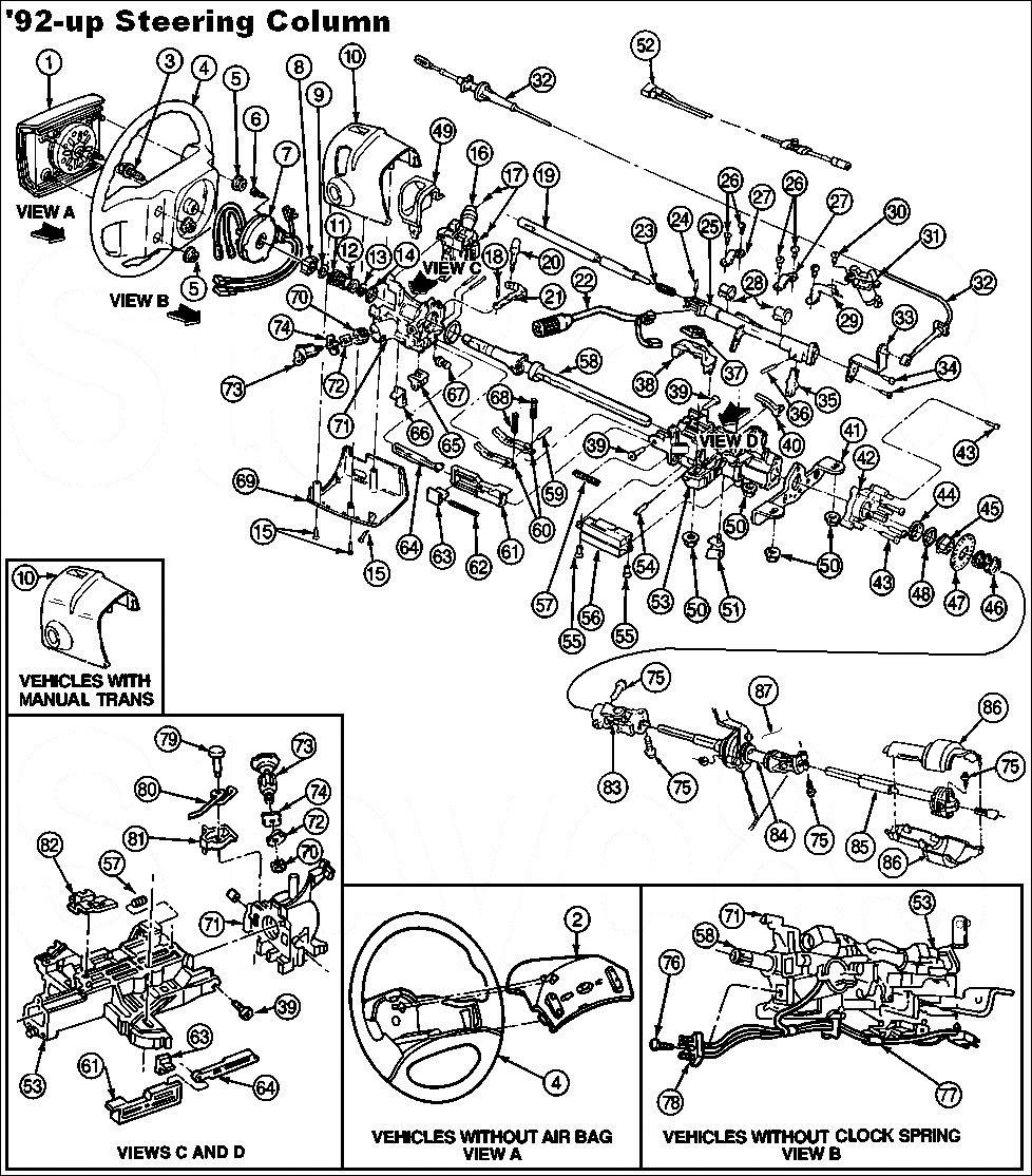
6 SPECIFICATIONS. OVERHAUL When overhauling steering columns, refer to exploded view illustrations. See Fig. 2. Fig. 2: Exploded View Of Steering Column With Air Bag Courtesy of FORD MOTOR CO. TORQUE SPECIFICATIONS TORQUE SPECIFICATIONS Application Ft. Lbs. (N.m) Intermediate Shaft-To-Steering Column Shaft Bolt (41-57) Thursday, January 22, :47:12 PM Page Mitchell Repair Information Company, LLC.
7 Steering Column-To-Support Bracket Retaining Nuts (14-19) Steering Wheel Retaining Bolt (31-45) INCH Lbs. (N.m) Air Bag Clockspring Contact Assembly Retaining Screws Aerostar, Van & Villager (2-3) Air Bag-To-Steering Wheel Retaining Nuts Aerostar, Van & Villager (4-6) Ignition Switch Retaining Screws ( ) Multifunction Switch Screws (2-3) PRND21 Cable Retaining Screw (7-11) Thursday, January 22, :47:12 PM Page Mitchell Repair Information Company, LLC.
8
9
1995 Mercury Grand Marquis GS
 AIR BAG SYSTEM CAUTION: Read the following safety precautions BEFORE servicing steering columns on vehicles equipped with air bag restraint system. ALWAYS wear safety glasses when servicing vehicle with
REMOVAL AND INSTALLATION Procedure revision date: 05/17/2000
 1997 Aerostar/Ranger REMOVAL AND INSTALLATION Procedure revision date: 05/17/2000 Module, Driver Side Air Bag NOTE: In general, if the air bag did not deploy in an accident, it was not needed. Complete
1997 Mazda MX-5 Miata. STEERING COLUMN STEERING Mazda Motors Corp. - Steering Columns STEERING Mazda Motors Corp. - Steering Columns
 Disable air bag system before servicing any air bag system or steering column component. See AIR BAG DISABLING & ACTIVATING. After disabling air bag system, wait at least one minute before servicing. Air
SECTION B: Supplemental Restraint System 2002 Lincoln LS Workshop Manual REMOVAL AND INSTALLATION Procedure revision date: 02/27/2004
 SECTION 501-20B: Supplemental Restraint System 2002 Lincoln LS Workshop Manual REMOVAL AND INSTALLATION Procedure revision date: 02/27/2004 Clockspring Removal WARNING: Always wear safety glasses when
1999 Explorer/Mountaineer Workshop Manual
 Page 1 of 16 SECTION 211-04: Steering Column 1999 Explorer/Mountaineer Workshop Manual DISASSEMBLY AND ASSEMBLY Procedure revision date: 07/27/1998 Steering Column Automatic Transmission Disassembly WARNING:
The steering column is of a modular construction and features easy to service electrical switches.
 file://c:\tso\tsocache\vdtom_5368\svk~us~en~file=svkb4a01.htm~gen~ref.htm Page 1 of 3 Section 11-04A: Steering Column, Ranger DESCRIPTION AND OPERATION 1997 Ranger Workshop Manual Steering Column NOTE:
2002 Escape Workshop Manual
 Page 1 of 6 SECTION 501-10: Seating 2002 Escape Workshop Manual REMOVAL AND INSTALLATION Procedure revision date: 01/07/2002 Seat Track Driver Seat Removal WARNING: Always wear safety glasses when repairing
DESCRIPTION & OPERATION
 AIR BAG RESTRAINT SYSTEM 1996 ACCESSORIES/SAFETY EQUIPMENT Toyota Air Bag Restraint System DESCRIPTION & OPERATION WARNING: To avoid injury from accidental air bag deployment, read and carefully follow
DESCRIPTION & OPERATION
 DESCRIPTION & OPERATION 2001 ACCESSORIES/SAFETY EQUIPMENT General Motors Corp. - Air Bag Restraint Systems WARNING: Accidental air bag deployment is possible. Personal injury may result. To avoid injury
ARTICLE BEGINNING DESCRIPTION DISABLING & ACTIVATING AIR BAG SYSTEM SERVICE PRECAUTIONS STEERING Volkswagen - Steering Columns.
 Article Text ARTICLE BEGINNING 1995-96 STEERING Volkswagen - Steering Columns Golf III WARNING: All models are equipped with a Supplemental Restraint System (SRS) that includes an air bag located in steering
STEERING COLUMN SWITCHES
 STEERING COLUMN SWITCHES 1995 Volvo 850 1995-96 ACCESSORIES & EQUIPMENT Volvo Steering Column Switches 850 TESTING NOTE: Testing information on steering column switches is not available from manufacturer.
STEERING Chrysler Motors/Mitsubishi - Steering Columns - FWD
 Article Text ARTICLE BEGINNING 1991-92 STEERING Chrysler Motors/Mitsubishi - Steering Columns - FWD Dodge; Colt, Colt 200, Colt Vista, Stealth Eagle; Summit & 1992 Summit Wagon Mitsubishi; Eclipse, Galant,
1991 Mazda MX-5 Miata AIR BAG RESTRAINT SYSTEM MAZDA AIR BAGS
 DESCRIPTION & OPERATION AIR BAG RESTRAINT SYSTEM MAZDA 1990-91 AIR BAGS WARNING: To avoid injury from accidental air bag deployment, read and carefully follow all WARNINGS and SERVICE PRECAUTIONS. The
All vehicles. 1. Turn all vehicle accessories OFF. system (SRS) vehicle and when handling an air bag module. This will reduce the risk of injury in
 vehicle and when handling an air bag module. This will reduce the risk of injury in") 501-20B-1 GENERAL PROCEDURES (SRS) Deactivation and Reactivation Special Tool(s) Diagnostic Tool, Restraint System 418-F403 Diagnostic Tool, Restraint System (2 required) 418-133 501-20B-1 WARNING: Never
501-20B-1 GENERAL PROCEDURES (SRS) Deactivation and Reactivation Special Tool(s) Diagnostic Tool, Restraint System 418-F403 Diagnostic Tool, Restraint System (2 required) 418-133 501-20B-1 WARNING: Never
STEERING COLUMN - TILT
 STEERING COLUMN - TILT 1993 Toyota Celica 1993 STEERING Toyota - Steering Columns - Tilt Wheel Celica DESCRIPTION & OPERATION Tilt steering wheels incorporate an upper steering shaft, attached by a "U"
STEERING COLUMN - TILT
 STEERING COLUMN - TILT 1994 Toyota Celica 1994 STEERING Toyota - Steering Column - Tilt Wheel Celica DESCRIPTION & OPERATION Tilt steering wheels incorporate a mainshaft, attached by a "U" joint to an
STEERING COLUMN - STANDARD
 STEERING COLUMN - STANDARD 1994 Toyota Celica 1994 STEERING Toyota - Steering Column - Standard Celica DESCRIPTION & OPERATION Steering column is a collapsible 2-piece design. Columns use shear pins to
2004 Toyota RAV ACCESSORIES/SAFETY EQUIPMENT Toyota - Air Bag Restraint Systems
 DESCRIPTION & OPERATION 2004 ACCESSORIES/SAFETY EQUIPMENT Toyota - Air Bag Restraint Systems WARNING: Accidental air bag deployment is possible. Personal injury may result. Read and follow all WARNINGS
1989 Jeep Cherokee. STEERING COLUMN' '1989 STEERING Jeep Steering Columns STEERING COLUMN STEERING Jeep Steering Columns
 STEERING COLUMN 1989 STEERING Jeep Steering Columns DESCRIPTION All models use collapsible steering columns. All columns have integral ignition switch and locking device. Optional tilt wheel is available
1999 Toyota RAV ACCESSORIES & EQUIPMENT Steering Column Switches - Trucks
 1999 ACCESSORIES & EQUIPMENT Steering Column Switches - Trucks DESCRIPTION WARNING: Deactivate air bag system before performing any service operation. See AIR BAG RESTRAINT SYSTEMS article. DO NOT apply
STEERING COLUMN SWITCHES
 STEERING COLUMN SWITCHES 1998 Pontiac Bonneville 1998 ACCESSORIES & EQUIPMENT General Motors Corp. - Steering Column Switches Buick; LeSabre Oldsmobile; Eighty Eight, LSS & Regency Pontiac; Bonneville
2005 Freestyle/Five Hundred/Montego Workshop Manual
 Page 1 of 8 SECTION 501-10: Seating 2005 Freestyle/Five Hundred/Montego Workshop Manual DISASSEMBLY AND ASSEMBLY Procedure revision date: 07/14/2006 Seat Backrest Front Printable View (466 KB) Special
AIR BAG RESTRAINT SYSTEM
 AIR BAG RESTRAINT SYSTEM 1994 Volvo 960 1994 ACCESSORIES/SAFETY EQUIPMENT Volvo Air Bags 940 & 960 * PLEASE READ THIS FIRST * WARNING: To avoid injury from accidental air bag deployment, read and carefully
This file is available for free download at
 This file is available for free download at http://www.iluvmyrx7.com This file is fully text-searchable select Edit and Find and type in what you re looking for. This file is intended more for online viewing
1993 ACCESSORIES & EQUIPMENT Volkswagen Steering Column Switches. Cabriolet, Corrado SLC, EuroVan, Fox, Golf, GTI, Jetta, Passat
 Article Text ARTICLE BEGINNING 1993 ACCESSORIES & EQUIPMENT Volkswagen Steering Column Switches Cabriolet, Corrado SLC, EuroVan, Fox, Golf, GTI, Jetta, Passat * PLEASE READ THIS FIRST * CAUTION: Cabriolet
DESCRIPTION & OPERATION
 CRUISE CONTROL SYSTEM 1997 ACCESSORIES/SAFETY EQUIP General Motors Corp. - Cruise Control System DESCRIPTION & OPERATION WARNING: To avoid injury from accidental air bag deployment, read and carefully
2002 Focus Workshop Manual
 Page 1 of 5 SECTION 211-04: Steering Column 2002 Focus Workshop Manual REMOVAL AND INSTALLATION Procedure revision date: 09/28/2004 Steering Column Removal WARNING: Wait at least one minute after disconnecting
STEERING COLUMN SWITCHES
 STEERING COLUMN SWITCHES 1994 Toyota Celica 1994 ACCESSORIES & EQUIPMENT Toyota Motor Sales, U.S.A., Inc. - Steering Column Switches Celica * PLEASE READ THIS FIRST * WARNING: Are equipped with a driver-side
MY F150 CrewCab 1. Tools Required 10X. Page 1 of 15 DL3J-19A014-AA Copyright Ford 2013 FoMoCo
 2013-2014MY F150 CrewCab 1 Tools Required A B C D E F G 4X H I J K 3X L 3X 2X 10X 2X Page 1 of 15 DL3J-19A014-AA Copyright Ford 2013 FoMoCo 2013-2014MY F150 CrewCab 2 Vehicles with selector lever in floor
TECHNICIAN SAFETY INFORMATION
 2009 Honda Accord L4-2.4L Vehicle > Restraints and Safety Systems > Air Bag Systems > Service Precautions TECHNICIAN SAFETY INFORMATION SRS Precautions and Procedures General Precautions NOTE: Some systems
Removal & Installation
 Page 1 of 11 2011 Nissan Rogue : Body > Interior > Instrument Panel > Removal & Installation Removal & Installation 1. Before servicing the vehicle, refer to the Precautions Section. CAUTION Always work
ALLDATA Online Dodge Truck RAM 1500 Truck 2WD V6-3.7L VIN K - Steeri... Steering Column
 Page 1 of 5 Home Account Contact ALLDATA Log Out Help PAUL REDEHOFT Select Vehicle New TSBs Technician's Reference Component Search: OK 2002 Dodge Truck RAM 1500 Truck 2WD V6-3.7L VIN K Conversion Calculator
PASSIVE RESTRAINT SYSTEMS
 TJ PASSIVE RESTRAINT SYSTEMS 8M - 1 PASSIVE RESTRAINT SYSTEMS CONTENTS page GENERAL INFORMATION INTRODUCTION... 1 DESCRIPTION AND OPERATION AIRBAG CONTROL MODULE... 3 AIRBAG MODULE... 2 CLOCKSPRING...
Revised : September 2015 September 2015 Dealer Service Instructions for: Safety Recall R36 Steering Wheel Wiring
 Revised : September 2015 September 2015 Dealer Service Instructions for: Safety Recall R36 Steering Wheel Wiring NOTE: Revised the parts information notes. Models 2012 2014 (DS) RAM 1500 Pickup 2012 2014
NO PART OF THIS DOCUMENT MAY BE REPRODUCED WITHOUT PRIOR AGREEMENT AND WRITTEN PERMISSION OF FORD PERFORMANCE PARTS
 Please visit www. performanceparts.ford.com for the most current instruction and warranty information. PLEASE READ ALL OF THE FOLLOWING INSTRUCTIONS CAREFULLY PRIOR TO INSTALLATION. AT ANY TIME YOU DO
LINCOLN. Continental 1
 3154_U01.qxd 8/1/03 7:28 AM Page 1 Continental 1 BRAKES...1-27 DRIVE TRAIN...1-21 ENGINE REPAIR...1-7 FUEL SYSTEM...1-20 PRECAUTIONS...1-7 SPECIFICATION CHARTS...1-2 STEERING AND SUSPENSION...1-22 A Air
REMOVAL & INSTALLATION
 REMOVAL & INSTALLATION Removal 1. Center steering wheel. Disconnect negative battery cable. Remove steering coupling shield (if equipped). Disconnect steering shaft at flexible coupling or pot joint. Note
C1219 C1219-STEERING ANGLE SENSOR ERRATIC PERFORMANCE RAM Pickup 6.7L Eng Search. 7/13/2015 Printer Friendly View
 2012 RAM Pickup 6.7L Eng 2500 1Search C1219 C1219-STEERING ANGLE SENSOR ERRATIC PERFORMANCE http://www2.prodemand.com/print/index?content=tabs&module=true&tab=true&terms=true&ymms=false&classname=&hideoptions=false
CRUISE CONTROL SYSTEM
 CRUISE CONTROL SYSTEM 1998 Pontiac Bonneville 1998 ACCESSORIES & EQUIPMENT General Motors Corp. - Cruise Control System Buick; LeSabre Oldsmobile; Eighty Eight, LSS & Regency Pontiac; Bonneville * PLEASE
Front Door Non-Functional - Latch Replacement
 Page 1 of 6 Home Account Contact ALLDATA Log Out Help DAN GRIMWOOD DAN GRIMWOOD00002 Select Vehicle New TSBs Technician's Reference Component Search: OK 2002 Ford Truck Escape 2WD L4-122 2.0L DOHC VIN
2003 Chevrolet Impala
 IGNITION SWITCH LOCK CYLINDER REPLACEMENT Removal Procedure IMPORTANT: Perform the body control module (BCM) theft deterrent relearn procedure whenever you replace the ignition switch lock cylinder. 1.
PASSIVE RESTRAINT SYSTEMS
 ZJ PASSIVE RESTRAINT SYSTEMS 8M - 1 PASSIVE RESTRAINT SYSTEMS CONTENTS page GENERAL INFORMATION INTRODUCTION... 1 DESCRIPTION AND OPERATION AIRBAG CONTROL MODULE... 3 AIRBAG MODULE... 2 CLOCKSPRING...
This file is available for free download at
 This file is available for free download at http://www.iluvmyrx7.com This file is fully text-searchable select Edit and Find and type in what you re looking for. This file is intended more for online viewing
Steering Column. Disassembly. 1. Remove instrument panel cover and reinforcement from vehicle as described in this section.
 Page 1 of 14 Section 11-04A: Steering Column, Ranger 1997 Aerostar/Ranger Workshop Manual DISASSEMBLY AND ASSEMBLY Procedure revision date: 05/17/2000 Steering Column Disassembly 1. Remove instrument panel
ARTICLE BEGINNING FUSES & CIRCUIT BREAKERS * PLEASE READ FIRST * ALL BUT JETTA ( ) Fuses & Circuit Breakers Volkswagen ELECTRICAL
 Fuses & Circuit Breakers Volkswagen ELECTRICAL") Article Text ARTICLE BEGINNING Fuses & Circuit Breakers 1987-96 Volkswagen ELECTRICAL FUSES & CIRCUIT BREAKERS * PLEASE READ FIRST * The fuse panel is located under the left side of the dash board by the
Article Text ARTICLE BEGINNING Fuses & Circuit Breakers 1987-96 Volkswagen ELECTRICAL FUSES & CIRCUIT BREAKERS * PLEASE READ FIRST * The fuse panel is located under the left side of the dash board by the
MANUAL TRANSMISSIONS. Servicing - Corvette. Transmission Model (RPO Code) Borg-Warner T56 6-Speed (M12)
 Borg-Warner T56 6-Speed (M12)") 2003-04 MANUAL TRANSMISSIONS Servicing - Corvette APPLICATION TRANSMISSION APPLICATION Application Corvette Convertible & Coupe Z06 Transmission Model (RPO Code) Borg-Warner T56 6-Speed (MM6) Borg-Warner
2003-04 MANUAL TRANSMISSIONS Servicing - Corvette APPLICATION TRANSMISSION APPLICATION Application Corvette Convertible & Coupe Z06 Transmission Model (RPO Code) Borg-Warner T56 6-Speed (MM6) Borg-Warner
2003 Chevrolet Impala LS
 MULTIFUNCTION, TURN SIGNAL SWITCH REPLACEMENT Removal Procedure Fig. 28: View Of Steering Column Wire Harness Assembly & Wire Harness Strap CAUTION: Refer to SIR Caution in Cautions and Notices. Tuesday,
DISASSEMBLY AND ASSEMBLY
 501-10-1 Seating 501-10-1 DISASSEMBLY AND ASSEMBLY Front Seat Cushion Special Tool(s) Worldwide Diagnostic System (WDS) Vehicle Communication Module (VCM) with appropriate adapters, or equivalent diagnostic
STEERING COLUMN SWITCHES
 STEERING COLUMN SWITCHES 1990 Nissan 240SX TESTING 1990 ACCESSORIES & EQUIPMENT Nissan - Steering Column Switches Axxess, Maxima, Pathfinder, Pickup, Pulsar NX, Sentra, Stanza, 240SX, 300ZX * PLEASE READ
1 of 13 5/11/17, 2:59 PM
 1 of 13 5/11/17, 2:59 PM REMOVAL WARNING: ON VEHICLES EQUIPPED WITH AIRBAGS, DISABLE THE AIRBAG SYSTEM BEFORE ATTEMPTING ANY STEERING WHEEL, STEERING COLUMN, OR INSTRUMENT PANEL COMPONENT DIAGNOSIS OR
SRS AIRBAG Toyota RAV4. Supplemental Restraint System - RAV4 PRECAUTION CAUTION:
 2005 RESTRAINTS Supplemental Restraint System - RAV4 SRS AIRBAG PRECAUTION CAUTION: The TOYOTA RAV4 is equipped with SRS that includes a driver airbag, front passenger airbag, side airbag and curtain shield
2. NOTE: On vehicles equipped with automatic transmissions, move the shift lever to the 1 position to ease removal.
 Page 1 of 28 Section 501-12: Instrument Panel and Console REMOVAL AND INSTALLATION 1997 F-150, F-250 Workshop Manual Instrument Panel Removal 1. WARNING: TO AVOID ACCIDENTAL DEPLOYMENT AND POSSIBLE INJURY,
A/C-HEATER SYSTEM - AUTOMATIC
 A/C-HEATER SYSTEM - AUTOMATIC 1994 Volvo 960 1994 Auto. A/C-Heater System Volvo 960 A/C SYSTEM SPECIFICATIONS AUTOMATIC A/C SYSTEM SPECIFICATIONS TABLE Application Specification Compressor Type... Sanden
ACCELERATOR CONTROL SYSTEM
 ENGINE SECTION ACC A ACC C D CONTENTS E PRECAUTION... 2 PRECAUTIONS... 2 Precaution for Supplemental Restraint System (SRS) "AIR BAG" and "SEAT BELT PRE-TEN- SIONER"...2 Precautions Necessary for Steering
WIPER/WASHER SYSTEM - FRONT ACCESSORIES & EQUIPMENT General Motors Corp. - Front Wiper/Washer System
 WIPER/WASHER SYSTEM - FRONT 1998 ACCESSORIES & EQUIPMENT General Motors Corp. - Front Wiper/Washer System DESCRIPTION & OPERATION CAUTION: To prevent scratching, wet the windshield before turning on wipers.
PASSIVE RESTRAINT SYSTEMS
 XJ PASSIVE RESTRAINT SYSTEMS 8M - 1 PASSIVE RESTRAINT SYSTEMS TABLE OF CONTENTS page DESCRIPTION AND OPERATION AIRBAG SYSTEM...1 DRIVER SIDE AIRBAG MODULE...2 PASSENGER SIDE AIRBAG MODULE....3 AIRBAG CONTROL
RS 413 SUPPLEMENTAL RESTRAINT SYSTEM CURTAIN SHIELD AIRBAG ASSEMBLY REMOVAL
 413 REMOVAL Use the same procedures for the RH side and LH side. The procedures listed below are for the LH side. 1. PRECAUTION Be sure to read "PRECAUTION" thoroughly before servicing (See page -1). 2.
PASSIVE RESTRAINT SYSTEMS
 DN PASSIVE RESTRAINT SYSTEMS 8M - 1 PASSIVE RESTRAINT SYSTEMS TABLE OF CONTENTS page DESCRIPTION AND OPERATION AIRBAG SYSTEM...1 DRIVER SIDE AIRBAG MODULE...2 PASSENGER SIDE AIRBAG MODULE....3 AIRBAG CONTROL
1 of 7 7/22/2013 8:41 AM
 1 of 7 7/22/2013 8:41 AM REMOVAL 1. Turn the steering wheel so that the vehicle's wheels are pointing straight ahead. 2. Turn the ignition switch to "LOCK". 3. Disconnect the battery "-" terminal cable,
 Page 1 of 13 2004 Chrysler PT Cruiser 2.4L Eng Touring Service Manual: AUTOMATIC TRANSMISSION - SERVICING ON-VEHICLE REPAIRS Tip: Trans pan leaking...maybe not. NOTE: Various components may be serviced
REMOVAL & INSTALLATION
 REMOVAL & INSTALLATION HEATED SEAT MODULE (HSM), MEMORY SEAT MODULE (MSM) OR MEMORY HEATED SEAT MODULE (MHSM) NOTE: After installation, initialize memory seat module. Move each power seat adjuster motor,
TURN SIGNAL AND HAZARD WARNING SYSTEMS
 DN TURN SIGNAL AND HAZARD WARNING SYSTEMS 8J - 1 TURN SIGNAL AND HAZARD WARNING SYSTEMS CONTENTS page GENERAL INFORMATION HAZARD WARNING SYSTEM... 1 INTRODUCTION... 1 TURN SIGNAL SYSTEM... 1 DESCRIPTION
RE22 Airbag Systems, Side
 Uniform Procedures For Collision Repair UPCR RE22 Airbag Systems, Side 1. Description This procedure describes methods for the repair, replacement, inspection, and testing of side airbag systems. Side
CRUISE CONTROL SYSTEM
 CRUISE CONTROL SYSTEM 1994 Toyota Celica 1994 ACCESSORIES & EQUIPMENT Toyota Motor Sales, U.S.A., Inc. - Cruise Control Systems Celica DESCRIPTION Cruise control system consists of Cruise Control Electronic
 Page 1 of 5 2003 Dodge Dakota 3.9L Eng Base 1Search Print Date: MULTIFUNCTION, TURN SIGNAL AND HAZARD SWITCH REMOVAL WARNING: DISABLE THE AIRBAG SYSTEM BEFORE ATTEMPTING ANY STEERING WHEEL, STEERING COLUMN,
SECTION B Supplemental Restraint System
 501-20B-i Supplemental Restraint System 501-20B-i SECTION 501-20B Supplemental Restraint System CONTENTS PAGE Restraints Control Module (RCM)... 501-20B-2 501-20B-2 Supplemental Restraint System 501-20B-2
Sensor A/C Ambient Temperature 1951
 SECTION 412-04: Control Components REMOVAL AND INSTALLATION Sensor A/C Ambient Temperature Removal 1. Remove the radiator upper sight shield. 2. Disconnect the wire harness connector. 3. Remove the A/C
RESTRAINT SYSTEM SECTIONRS CONTENTS IDX. SEAT BELTS...3 Precautions...3. Passenger Air Bag Deactivation Switch Indicator...27
 RESTRAINT SYSTEM SECTIONRS GI MA EM LC EC CONTENTS FE SEAT BELTS...3 Precautions...3 SUPPLEMENTAL RESTRAINT SYSTEM (SRS) AIR BAG AND SEAT BELT PRE-TENSIONER...3 PRECAUTIONS FOR SEAT BELT SERVICE...3 AFTER
1994 Mazda B4000 SE. CRUISE CONTROL SYSTEM 1994 ACCESSORIES/SAFETY EQUIPMENT Mazda Cruise Control System
 DESCRIPTION Cruise control system consists of control switches located on steering wheel, servo throttle actuator assembly, speed sensor mounted on transmission (transfer case on 4WD), clutch switch (M/T),
IMPORTANT: When replacing the ignition lock cylinder only, the passlock relearn procedure is not required.
 A 1 of 11 2/18/2012 3:27 PM IMPORTANT: The important statement at the beginning of the "Ignition Lock Cylinder removal procedure on page 188 in the 2000/2001 Saturn S-Series Body/Electrical Volume II Service
 Page 1 of 12 1Search INSTRUMENT CLUSTER 2008 Dodge Dakota 3.7L Eng DIAGNOSTIC CODE INDEX DIAGNOSTIC CODE INDEX DTC B1200 B1201 B1613 B1615 B2107 B2213 B222C P0930 P0931 U0019 U0141 U0151 U0156 U0168 U0184
2004 Lexus LS430. Submodel: Engine Type: V8 Liters: 4.3 Fuel Delivery: FI Fuel: GAS
 2004 Lexus LS430 Submodel: Engine Type: V8 Liters: 4.3 Fuel Delivery: FI Fuel: GAS OVERHAUL If the airbag connector is disconnected with the ignition switch in the ON position, DTCs will be recorded. When
REMOVAL WJ INSTRUMENT PANEL SYSTEM INSTRUMENT PANEL SYSTEM (Continued)
") WJ INSTRUMENT PANEL SYSTEM 23-127 entire structural duct unit must be replaced. Most other trim and functional components of the instrument panel are available for service replacement separately from the
WJ INSTRUMENT PANEL SYSTEM 23-127 entire structural duct unit must be replaced. Most other trim and functional components of the instrument panel are available for service replacement separately from the
REMOVAL AND INSTALLATION
 501-01-1 Body System Interior 501-01-1 REMOVAL AND INSTALLATION Instrument Panel CAUTION: Electronic modules are sensitive to static electrical charges. If exposed to these charges, damage may result.
8N - 18 POWER WINDOWS
 8N - 18 POWER WINDOWS PT POWER WINDOWS (Continued) will grunt and the inner door panel will flex when actuated in that one direction. (6) Reverse jumper probes at the motor connector terminals and window
DOOR LOCKS, TRUNK LID & FUEL DOOR - POWER. Entire Article
 ARTICLE BEGINNING 1999-2000 ACCESSORIES & EQUIPMENT Lexus Power Door Locks, Trunk Lid & Fuel Door RX300 DESCRIPTION POWER DOOR LOCKS All doors can be locked and unlocked from either front door using control
HORNS 8G - 1 HORNS CONTENTS
 J HORNS 8G - 1 HORNS CONTENTS page DIAGNOSIS... 2 GENERAL INFORMATION... 1 page SERVICE PROCEDURES... 3 SPECIFICATIONS... 5 GENERAL INFORMATION Following are general descriptions of the major components
2003 Cadillac DeVille DTS
 TRIM PANEL REPLACEMENT - SIDE FRONT DOOR Tools Required J 36796 Clip Zip Clip Removal Tool, or J 38778 Door Trim Pad Clip Remover Removal Procedure 1. Position the window fully downward. 2. Ensure the
2007 Pontiac G BRAKES Disc Brakes - G6
 REAR DISC BRAKE PADS REPLACEMENT Removal Procedure CAUTION: Refer to Brake Dust Caution. 1. Inspect the fluid level in the brake master cylinder reservoir. 2. If the brake fluid level is midway between
2001 Chevrolet Corvette ACCESSORIES & EQUIPMENT Headlight Doors - Corvette
 DESCRIPTION & OPERATION 2001 ACCESSORIES & EQUIPMENT Headlight Doors - Corvette Headlight doors are actuated by reversible electric motors mounted near each headlight door. Battery voltage is applied at
2002 Dodge Intrepid ES ACCESSORIES & EQUIPMENT Anti-Theft Systems - Concorde, Intrepid & 300M
 DESCRIPTION SENTRY KEY IMMOBILIZER SYSTEM 2002-03 ACCESSORIES & EQUIPMENT Anti-Theft Systems - Concorde, Intrepid & 300M CAUTION: Large metallic objects, or items such as magnetic pass-keys, may cause
SUBJECT: While In Bi-level Mode, Air Flow From Panel Vents Is Less Than That Of The Floor Vents
 NUMBER: GROUP: 24-20-99 Rev. A Heating & A/C DATE: Dec. 17, 1999 This bulletin is supplied as technical information only and is not an authorization for repair. No part of this publication may be reproduced,
DISPOSAL HINT: CAUTION: Never dispose of the horn button assy that has an undeployed
 DISPOSAL 6015 When scrapping a vehicle equipped with the SRS or disposing of the horn button assy, be sure to deploy the airbag first in accordance with the procedure described below. If any abnormality
DESCRIPTION & OPERATION
 ANTI-THEFT SYSTEM 1998 ACCESSORIES & EQUIPMENT General Motors Corp. - Anti-Theft System DESCRIPTION & OPERATION WARNING: Deactivate air bag system before performing any service operation. See AIR BAG RESTRAINT
2000 Dodge Durango ACCESSORIES & EQUIPMENT' 'Power Windows - Dakota & Durango 2000 ACCESSORIES & EQUIPMENT. Power Windows - Dakota & Durango
 DESCRIPTION & OPERATION 2000 ACCESSORIES & EQUIPMENT Power Windows - Dakota & Durango A permanent magnet motor moves each of the power windows. A master switch on driver's door controls all windows and
ARTICLE BEGINNING SERVICE PRECAUTIONS
 Page 1 of 96 ARTICLE BEGINNING SERVICE PRECAUTIONS WARNING: WARNING: CAUTION: When performing any inspection or service procedure on this vehicle, ensure following service precautions are followed to prevent
ALLDATA Online Chevy Truck Avalanche WD V8-5.3L VIN T - Steering... Page 1 of 12. Steering Wheel Module Coil Replacement (Coil)
") ALLDATA Online - 2006 Chevy Truck Avalanche 1500 2WD V8-5.3L VIN T - Steering... Page 1 of 12 Steering Wheel Module Coil Replacement (Coil) INFLATABLE RESTRAINT STEERING WHEEL MODULE COIL REPLACEMENT (COIL)
ALLDATA Online - 2006 Chevy Truck Avalanche 1500 2WD V8-5.3L VIN T - Steering... Page 1 of 12 Steering Wheel Module Coil Replacement (Coil) INFLATABLE RESTRAINT STEERING WHEEL MODULE COIL REPLACEMENT (COIL)
ARTICLE BEGINNING INTRODUCTION IGNITION SYSTEM CAMSHAFT POSITION (CMP) SENSOR DISTRIBUTOR
 SENSOR DISTRIBUTOR") Article Text Thursday, August 19, 1999 11:40PM ARTICLE BEGINNING 1996 ENGINE PERFORMANCE Volkswagen Removal, Overhaul & Installation - Gasoline Cabrio, Golf III, GTI, Jetta III, Passat CAUTION: When battery
Article Text Thursday, August 19, 1999 11:40PM ARTICLE BEGINNING 1996 ENGINE PERFORMANCE Volkswagen Removal, Overhaul & Installation - Gasoline Cabrio, Golf III, GTI, Jetta III, Passat CAUTION: When battery
Z-Gate Universal Shifter
 Installation Instructions Z-Gate Universal Shifter Fits: GM, Ford, Lincoln and Chrysler Transmissions See Application Guide for Specific Applications Part #80681 Rev 06/01/2018 WORK SAFELY! For maximum
Airbags, servicing. Airbag system, safety precautions WARNING!
 Page 1 of 75 69-40 Airbags, servicing Airbag system, safety precautions Checking, removing, installing and servicing may ONLY be performed by qualified personnel. Never perform tests using a test light
2001 Chevrolet Corvette ACCESSORIES & EQUIPMENT Cruise Control Systems - Corvette
 2001 ACCESSORIES & EQUIPMENT Cruise Control Systems - Corvette DESCRIPTION Cruise control is a speed control system that maintains a desired vehicle speed under normal driving conditions. Steep grades
REMOVAL AND INSTALLATION
 501-20B-1 REMOVAL AND INSTALLATION 501-20B-1 Occupant Classification Sensor Item Part Number Description 7 61704 Seat track assembly Special Tool(s) 8 Safety belt buckle switch electrical connector (part
MIRRORS - POWER Pontiac Bonneville DESCRIPTION TROUBLE SHOOTING SELF-DIAGNOSTICS DIAGNOSTIC PROCEDURE RETRIEVING DIAGNOSTIC TROUBLE CODES (DTCS)
") MIRRORS - POWER 1998 Pontiac Bonneville 1998 ACCESSORIES & EQUIPMENT General Motors Corp. - Power Mirrors Pontiac; Bonneville DESCRIPTION One mirror control switch adjusts both left (driver side) and right
MIRRORS - POWER 1998 Pontiac Bonneville 1998 ACCESSORIES & EQUIPMENT General Motors Corp. - Power Mirrors Pontiac; Bonneville DESCRIPTION One mirror control switch adjusts both left (driver side) and right
FORD BRONCO BODY LIFT KIT INSTALLATION INSTRUCTIONS KIT # KIT #843
 FORD BRONCO BODY LIFT KIT INSTALLATION INSTRUCTIONS 1992-1996 2 KIT #842 1992-1996 3 KIT #843 This kit should only be installed on a vehicle that is in good working condition. Before you install the kit,
 Page 1 of 11 1Search FRAME CROSS BAR 2001 Chrysler PT Cruiser 2.4L Eng Base CAUTION: DO NOT attempt to modify any suspension or steering components by heating or bending. Removal [ STABILIZER BAR ] 1.
RESTRAINT SYSTEM SECTIONRS CONTENTS IDX. SEAT BELTS...3 Precautions...3. Front Passenger Air Bag Module...24
 RESTRAINT SYSTEM SECTIONRS GI MA EM LC EC CONTENTS FE SEAT BELTS...3 Precautions...3 SUPPLEMENTAL RESTRAINT SYSTEM (SRS) AIR BAG AND SEAT BELT PRE-TENSIONER...3 PRECAUTIONS FOR SEAT BELT SERVICE...3 AFTER
SECTION 1A3 - INSTRUMENT PANEL AND CONSOLE
 SECTION 1A3 - INSTRUMENT PANEL AND CONSOLE Click on the button for more information. CAUTION: This vehicle will be equipped with a Supplemental Restraint System (SRS). A SRS will consist of either seat
1995 Jeep Grand Cherokee Limited. CRUISE CONTROL SYSTEM' '1995 ACCESSORIES & SAFETY EQUIPMENT Chrysler Corp. Cruise Control Systems
 TROUBLE SHOOTING NO CRUISE CONTROL WHEN SET BUTTON IS PRESSED & RELEASED Check for: blown fuse, no vacuum at servo and/or defective servo, disconnected speed control cable, brakelight switch out of adjustment,
Multi-Function Switch
 1 of 9 Nissan Frontier, Xterra 1998-05 Multi-Function Switch REMOVAL & INSTALLATION Fig. Multi-function switch component locations 1998-2000-2000 shown Before servicing, or working around, the SRS system,
ANTI-LOCK BRAKE SYSTEM
 ANTI-LOCK BRAKE SYSTEM 1995 Chevrolet Tahoe 1995 BRAKES General Motors Corp. - Anti-Lock - 4WAL Chevrolet: Pickup, Tahoe GMC: Sierra, Suburban, Yukon MODEL IDENTIFICATION Vehicle model can be identified