SN SERIES 1,000V. EN ver 03_2017
|
|
|
- Edwin Strickland
- 5 years ago
- Views:
Transcription
1 EN ver 03_2017 SN SERIES 1,000V Copyright S-Energy all rights reserved. 1 S-Energy PV Module Installation Manual S-Energy PV Module Inastallation Manual 1
2 Rev history S-Energy PV Module Installation Manual
3 INDEX Chapter Page No. Before Use Accessories Safety Precautions Environmental Considerations Caution before Installation Caution when Installed Electrical Installation Grounding Method Mechanical Installation Maintenance Cleaning Instructions Detailed Module Specification Installation Instructions 13 S-Energy PV Module Installation Manual
 produced and sold by S-Energy. Please store this manual in the visible area for future reference after installation.")
4 l Before Use 1) This installation manual (hereinafter referred to as "this manual") includes installation and maintenance methods, and important safety instructions for the PV module(hereinafter referred to as "PV module") produced and sold by S-Energy. Please store this manual in the visible area for future reference after installation. 2) 3) Any troubles caused by failure to comply with these instruction during the installation, use, operation, maintenance of the module may be excluded for warranty. All installation, operation shall be based on this manual, and the actual installation, use, operation and maintenance should be performed by qualified personnel with electrical license. 4) 5) 6) For the detailed quality warranty policy of the product, please refer the quality assurance provided by S-Energy Co., Ltd.. When the contents of this manual conflict with the quality assurance, the quality assurance takes precedence. In order to provide better service, the information included in this manual is subject to change without prior notice. 1. Accessories The name of each part of solar module is presented as 'Fig. 1'. When requesting maintenance, please inform malfunction part and its performing status including the name of each part by referencing the left figure. < Fig. 1 > 01 S-Energy PV Module Installation Manual


5 2. Safety Precautions These Safety Precautions should be thoroughly understood before installing. DANGER When connecting with '+', '-' in module, the cable shall be equipped with direct current, and shall not connect or disconnect with module when electricity flows. If an abnormal or old electrode is connected, you may get injured by sparks arising from direct current. PV module installation should be performed by qualified person only. CAUTION CAUTION RECOMMENDATION The utmost care is required for preventing corrosion/ contamination/deterioration due to mishandling when you load/outdoor load/installation. Store a module in an indoor warehouse before installing. Always wear protective equipment while working with PV modules. Working on a PV system requires following all applicable local codes and wearing protective equipment, and must be performed by appropriately qualified and authorized personnel only. Do not place heavy objects on the module. Stepping on or allowing objects to fall on the module may damage certain parts of the product and slow down the performance significantly, or causes risks to the whole system. Do not install when snowy, rainy, and windy days. Do not install where water remains on the ground. Install when the weather is clear. All surfaces and corners are fragile, so touch only the frame areas when moving/installing. And do not allow direct shock or hit to the module. PV module should be installed by a two person team. Be careful when handling because the shock may cause damage or low performance. 02 S-Energy PV Module Installation Manual


![] Prohibited connecting diagonally Male & Female when electrical [connector]](/docs-images/96/128725349/images/6-6.jpg "connecting. [Resulting in poor contact.")
![] Do not touch or give shocks to the Junction box as well as front and rear](/docs-images/96/128725349/images/6-7.jpg "surface of module, and do not remove the label.")

6 3. Environmental Considerations ENVIRONMENTAL CONSIDERATIONS 1) 2) The shading of the front surface is the main cause of hot spot or performance reduction of power generation. The ground should have well drained soil. CAUTION Do not scratch by a sharp tool on the module frame and surface. Abrasion of the coated surface may lead to oxidize frames or reduce their strength.the scratch of the surface may be the main cause of the module output degradation and decrease in strength. CAUTION Prohibited taking J-box cable when you handle the modules. [Resulting in electrical disconnection.] The front surface of the module shall not be exposed to sunlight artificially. [It can cause performance degradation due to solar cell degradation.] Prohibited connecting diagonally Male & Female when electrical [connector] connecting. [Resulting in poor contact.] Do not touch or give shocks to the Junction box as well as front and rear surface of module, and do not remove the label. Cable outer diameter of 8mm/ Recommended by more than 48mm radius of curvature. [Cable minimum bend radius is more than 6 times the cable diameter when wiring.] Do not touch with wet hands or equipment, which can result in electric shock. Cable wiring securely fixed to prevent shaking in the wind with cable tie. [However, consider summer/winter thermal expansion/contraction.] 03 S-Energy PV Module Installation Manual
7 4. Caution before Installation Please read this instruction before installing PV module. 1) 2) 3) 4) 5) 6) 7) 8) 9) The installation of PV module should be performed by qualified personnel only. When installing PV module, you should wear protective equipment. [electric shock or falling accident risk.] When installing PV module, do not step up onto the PV module or place the object on it. After installation, qualified person shall check whether it operates properly or not. Disassembling or replacing of the PV module part is not allowed without permission by manufacturer, and if you disassemble or replace anything, please inform the PV module manufacturer. When disassembling or replacing the part with manufacture s permission, it should be performed by qualified person only, and use the certified accessories. All installation work most be done to meet the local applicable standards, such as the recent National Electrical Code or National Electrical Standards. When the PV module is damaged or stopped, anyone, even who has useful knowledge for the PV module, should not approach to the PV module. Touch or approach may cause serious injury, in which case manufacturer is not responsible for the damage therefrom. PV module s orientation shall be at equator direction, and be installed at the same angle as the latitude of the installation location for the optimal generation performance. If it is installed at a different angle or direction, it may adversely affect an annual generation capacity. In case of horizontal installation, S-Energy recommends regular cleaning to remove dust on the surface. 10) PV module generates the voltage even without load connection. So, be careful for sparks especially when assembling / disassembling PV module. 11) PV module is intended to be installed on the ground or building. If you need to install on the vehicle(car, train, etc.) or ship, please request special modules. 12) Snow, water, dust, or other foreign substance on the surface may increase reflection of the light and eventually reduce the PV module s output. [Regular cleaning of module surface can improve performance.] 13) 14) 15) 16) 17) Standard specifications was measured at STC rating conditions, temperatures can get very effective in increasing power generation is low. Before installation, modules should be stored under packing condition. Irrespective of module connection, contacting current carrying part may cause a burn or fatal electrical shock from sparks. The shading of the front surface of the module can cause the module degradation by fire or reduce its lifecycle. When working with the PV module wire, connect the wire with a hanger to avoid contact on the roof or ground. 18) Dual glass modules do not present any exposed conductive parts, and therefore do not require to be electrically grounded for compliance to the National Electrical Code. 19) Do not use or install broken modules; Failure to comply may result in fire, electric shock, and injury. 5. Caution when Installed 1) 2) 3) 4) 5) 6) Please make sure that installed module wire distribution is correct, and insulation and waterproof performance of connect part is suitably installed. Check if there are any scratches on the frame and front surface of the glass. [The scratch may lead oxidation and reduce the strength.] Regularly clean the module with water, and if the module is not cleaned with water, request to the manufacturer. [Regular cleaning can significantly improve the output capacity.] The front surface of glass is specially treated, so do not apply any abrasive cleaning product or chemicals. Periodic inspection should be performed only by qualified personnel with protective equipment. To avoid shade by the vegetation environment, regular weeding is needed. 04 S-Energy PV Module Installation Manual
8 6.Electrical Installation 1) 2) 3) 4) 5) 6) 7) 8) 9) 10) 11) CAUTION Electrical risks must be prevented during installation, distribution, generation, and maintenance of PV module. During installation of PV module, system voltage should not exceed. [IEC 1000V] When installing the system, use same rate of model. [If you use a electrically and physically different type of module, output capacity or system performance may be reduced due to fire.] When wiring, you should connect polarity appropriately, and if not, it can cause abnormal generation performance and PV module degradation by fire. For the reverse current value, refer the Fuse rating value specified in '9. Detailed module specification'. If exceed its value, connect the rated overcurrent protective device(permitted by local regulation) to the module string in series wiring. Junction box is in the rear surface of the module. This box is an important device for the module generation, and never unpack it in any circumstance in the field. [Once the junction box is opened, warranty will be invalidated.] If the PV module have any electrical problem, you should inspect the module according to the warranty term provided by S-Energy, and return it to S-Energy for repair and replacement. The fire rating of this module is valid only when mounted in the manner specified in the mechanical mounting instructions. The module is considered to be in compliance with UL 1703 only when the module in mounted in the manner specified by the mounting instructions below. A module with exposed conductive parts is considered to be in compliance with UL 1703 only when is electrically grounded in accordance with the instructions presented below and the requirements of the National Electrical Code. Any module without a frame (laminate) shall not be considered to comply with the requirements of UL 1703 unless the module with hardware that has been tested and evaluated with the module under this standard or by a field inspection certifying that the installed module complies with the requirements of UL In normal conditions, PV modules may produce larger current and/or voltage than reported in the standard test conditions. Therefore, when voltage evaluations for components, capacity of conductors, size of fuses, and size of control systems connected to the module output are determined, multiply the values of short- circuit current (Isc) and open-circuit voltage (Voc) that are marked in SN series modules by the NEC, 1.25 (Source: American National Electrical Code) A. Series Wiring B. Parallel Wiring < SERIES WIRING [VOLTAGE ADDED] > Wires may be connected in series to generate the required voltage output. Series wiring should be configured at the same rate. (current) Only for UL 1703, When wires are connected in series, the maximum voltage should be under 800Vdc that is 80% of system Voltage 1000Vdc < PARALLEL WIRING [CURRENT ADDED] > Wires may be connected in parallel to generate the required current output. Even when wires are connected in parallel, the intensity of voltage in inverter should be considered. Before connected to other modules, all modules should be wired with a fuse. For the number of additional fuses and maximum number of module should refer and follow the related local regulations. Material : All the wire for the PV module connection should be configured with PV cable only. [Cable for PV : double insulation, UV resistance, temperature resistant for more than minimum 90 ] Use copper wire for all wiring. Diameter: At least larger than minimum 12AWG. [4mm 2 ] [wiring diameter should confirm the local regulation, and S-Energy Co., Ltd. recommends the customer use wires with a diameter larger than the above number at minimum.] Module configuration[series wiring] [{(Min Temp 25 ) x (Voc x -Temperature coefficient of Voc)} + Voc] x Panels per string = Maximum system Voltage To guarantee the maximum voltage limitation condition, ensure the general temperature condition according to the National Electric Code (690.7) 05 S-Energy PV Module Installation Manual
9 7. Grounding Method For preventing electric shock and fire, the frame of PV module shall be grounded properly. [Please be sure to remove a coated portion when grounding, because the PV module aluminum frame is coated with anodizing.] Configuration A Size and material M4 Bolt Remarks 16 mm Materials - SUS304: Bolt, Nut, Washer (Steel Use Stainless) - Grounding wire: Copper B C M4 Star washer M4 Plat washer Torque: 0.9Nm ~ 1.1Nm For the detail of Earth, refer to NEC(National Electric Code) 690 grounding PV arrays for special requirements. D M4 Cup washer E Grounding wire 12 AWG F M4 Plat washer G M4 Nut Where common grounding hardware (nuts, bolts, star washers, spilt-ring lockwashers, flat washers and the like) is used to attach a listed grounding/bonding device, the attachment must be made in conformance with the grounding device manufacturer s instructions. Common hardware items such as nuts, bolts, star, washers, lock washers and the like have not been evaluated for electrical conductivity or for use as grounding devices and should be used only for maintaining mechanical connections and holding electrical grounding devices in the proper position for electrical conductivity. Such devices, where supplied with the module and evaluated through the requirements in UL 1703, may be used for grounding connections in accordance with the instructions provided with the module. 06 S-Energy PV Module Installation Manual
10 8.Mechanical Installation 1) Grade[Class A]: The module is a 'Class A' grade. Class A: This grade is regarded as a device operated above 50V or above 240W and a product where an ordinary person's approach is expected. It acquired the safety standard under IEC and IEC ) Installation site: The module should be installed at a place satisfying the following Respect. Safety load A 60/72 cells series products were designed to tolerate the wind load(the back side) of 30lbs/ft²(UL 1703) and 2400Pa(IEC 61215), snow load(the front side) of 30lbs/ft²(UL 1703) and 5400Pa(IEC 61215). When the maximum snowfall and wind load on the site are above the standard, a structure to install the module on should be designed to satisfy the mechanical load of the site. Operating temperature A ambient temperature of module installation site is limited by the minimum and maximum temperature as shown below. [Considerations when temperature rises: output is reduced due to characteristics of the module.] - Maximum operating temperature: +85 [Under the hot temperature, ventilation should be considered.] - Minimum operating temperature: -40 Places where the installation is prohibited - A site directly contacting salt injury. - A site having poor drainage. [Poor drainage can shorten the module life.] - A site having a shade caused by the geographic features of the surrounding area. - A site where stones and foreign matters are often thrown near to the modules. [There are concerns for damage to the front window of the module.] - The heating properties of extremely high gas or vapor (filling stations, gas cylinders, paint, etc.) nearby flame or combustible materials Unit: mm [inch] G Drainage Hole 5 [1.97] R [4.33] 19.5 [7.68] 8.5 [3.35] Grounding Hole F E 1000 [39.37] Mounting Hole Junction Box C Screw End Frame G Side Frame G Corner Key G G A B D < Back View > < Side View > Unit: mm Position A B C D E F G 60 Cells Series / Cells Series S-Energy PV Module Installation Manual
 Confirmation matter a) b) To improve module's electrical insulation and durability, the back side [Junction Box] of module should be protected to avoid exposure to moisture, and PV module wiring")
11 How to use a frame installation hole 1) How to use a frame installation hole Please install the module at the angle having the most annual cumulative amount of solar radiation in the applicable site. 2) Confirmation matter a) b) To improve module's electrical insulation and durability, the back side [Junction Box] of module should be protected to avoid exposure to moisture, and PV module wiring should be installed considering thermal expansion due to ambient temperature and vibration due to wind. When a PV module is installed on a roof, between the back side of the PV module and roof is maintained at a sufficient distance(minimum above 2 inch) to be well ventilated. c) d) According to the laws of the applicable site, the PV module can be installed on a fire resistance roof. For UL 1703, the PV module's system class A fire rating. And for IEC 61730, the fire rating is 'C'. e) Only for UL 1703, the modules with the specified construction in below table, when used with a Listed mounting system that has been rated as a Class A System when installed with type 1 or type 2 modules, is suitable to maintain the System Class A Fire Rating. f) Only for UL 1703, The fire rating of the module is valid only when mounted in the manner specified in the mechanical mounting instructions. 3) Installation hole The method of installing a frame hole passed a mechanical load test item in accordance with the IEC and UL 1703 standard, and S-Energy Co., Ltd. recommends the following method of installing a frame hole. As described in <fig. 1>, an installation hole is inserted in the frame, if the frame is randomly processed or the installation hole is changed, the module will be damaged or the strength of frame will be declined. Hole Installation < Fig. 1 > - Bolt Torque: 5Nm ~ 7Nm (Newton-meters) - 60 Cells Series Bolt size: M6 L16 Bolt (PV Support T : 4mm) - 72 Cells Series Bolt size: M6 L20 Bolt SNxxxP-10 Specific construction Superstrate: 2.8 mm thick EVA: 0.45 mm thick Substrate: mm Frame: 1970 * 990 * 40 mm Cross sectional dimension: 33 * 40 mm Height: 40 mm Thickness: 1.8 mm Superstrate: 2.8mm thick EVA: 0.45mm thick Substrate: mm Frame: 1970 * 990 * 40mm Cross sectional dimension: 33 * 40 mm Height: 40 mm Thickness: 1.8 mm Marking Module Fire Performance: Type 2 Module Fire Performance: Type 1 CAUTION 1) 2) 3) Be careful to avoid sealing the gap between the module and the structure, because the area should be well ventilated. The module of power performance and life can be affected, if the space between the module and structure is sealed. Please leave a space between the modules because the module can be expanded or be shrink depending on the ambient temperature. In case of failure to use the accessories recommended by S-Energy Co., Ltd., it may affect the long term reliability of the module, and S-Energy Co., Ltd. do not take any responsibility for life-shortening of the module resulting from such use. 08 S-Energy PV Module Installation Manual
12 09. Maintenance S-Energy Co., Ltd. to ensure optimal performance of the module, it is recommended to maintain. 1) 2) To ensure the electrical and mechanical safety of module, check the electrical and physical connection on a regular basis. Modules and structural loosening bolts, check that there are indisposition grounded and the ground wire corrosion. Please confirm that no shading occurs due to the surrounding vegetation and buildings in front of the module. Junction box and connectors, check that there are no loose and damaged the fixed site. To maintain a stable generation performance please check the regularly around the module front and rear. Please confirm that there are no front glass breakage. Please check back Backsheet there is burnout. Make sure there are no heat problems during generate of the module. Please confirm that no modification coating module wiring section and burnout. CAUTION Installation and maintenance of the photovoltaic modules must be carried out only by qualified personnel held. Wear safety equipment during maintenance. Maintenance of the photovoltaic modules other components, please refer to the vendor Maintenance Manual. 10. Cleaning Instructions The front glass of the modules produced in S-Energy Co., Ltd. is using the general low iron glass and the ARC glass to minimize with light reflection. Cleaning time is taking into account the thermal shock and power generation, please proceed early in the morning and cloudy weather. Cleaning method and procedure Step 1: Off bets Such as dry leaves and debris on the module surface will have to pay it off with a dry cloth or dust tremble. If there is debris on the module surface, cleaning of these steps will be omitted because it is completed. Step 2: Wipe Dirt, bird secretions, twigs, leaves, etc., if solid foreign objects attached to the module, please wipe gently with a soft cloth that do not cause injury to the module. Step 3: Rinse bet Bird secretions, unable to shake off the dust cause of external humidity or plant essences such as colored debris on the module surface, should be removed by rinse bet method. For the colored debris remove give heavy water sprayed on the affected area and wipe gently with a soft cloth, makes regular cleaning necessary. CAUTION S-Energy modules are designed to withstand pressure 30lbs/ft²(UL 1703) and 5,400Pa(IEC 61215). If you decide to clean the snow in order to ensure the long-term growth and performance of the power generation module, the module's surface, do not remove the ice. Scratch the surface can be generated. There is a danger of electric shock, broken glass and broken wires, exposed wires, do not wash. Do not use the grinding dust, polish, sodium, benzene, alkali, and other chemical substances. 09 S-Energy PV Module Installation Manual
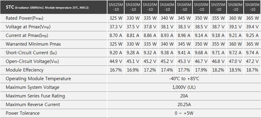
13 11. Detailed Module Specification (IEC) 10 S-Energy PV Module Installation Manual
14 11 S-Energy PV Module Installation Manual
15 11. Detailed Module Specification (UL) 12 S-Energy PV Module Installation Manual

16 13 S-Energy PV Module Installation Manual 20 20
17 12. Installation Instructions 1) Hole installation method A. General installation [minor axis installation] B. General installation [major axis installation] A Hole A Hole A Hole Width: > 50mm C. Special installation [minor axis installation] The following installation method is recommended by S-Energy for the installation of the PV module on a roof in heavy snow regions. A Hole Perform additional fastenings at the bottom of the module s minor axis frame. [Preventing load concentration due to the installation slope.] A Hole CAUTION Width: > 50mm Failure to remove accumulated snow on the PV module for long time may cause long-term power reduction. 200±20 14 S-Energy PV Module Installation Manual


 - Clamp")


18 2) Location and method of clamp installation - : Clamp installation location (A position Confirm "7 mechanical installation" module drawing) - Clamp width : 50mm or wider A Position A Position Cells Series 72 Cells Series 345 Module Clamp Assembly 3) Additional Grounding Methods 15 S-Energy PV Module Installation Manual
19 S-Energy Co., Ltd. H E A D O F F I C E C O N T A C T Fl3, MiraeAsset Tower, 20, Pangyoyeok-ro 241 beon-gil Bundang-gu, Seongnam, Gyeonggi-do, 13494, Republic of KOREA Tel Fax energycare@s-energy.com
Safety and Installation Instructions
 Safety and Installation Instructions This document applies to the following UL-listed Gloria Solar Standard Modules: GSM6- series GSS6- series Rev: 1.2 Release Date: September 03, 2009 Gloria Solar Co.,
Copyright 2012 DelSolar Co. Ltd MQWRD installation manual-iec Ver. 1.4
 INSTALLATION MANUAL IEC Version www.delsolarpv.com Copyright 2012 DelSolar Co. Ltd MQWRD-01-14--installation manual-iec Ver. 1.4 Content General information 1 Safety precaution for installing solar PV
INSTALLATION MANUAL THE / MODULE. IEC & UL version
 INSTALLATION MANUAL IEC & UL version THE / MODULE Duomax Duomax Duomax M Plus TSM-PDG40.40 TSM-PDG40.47 TSM-PDG5.40 TSM-PDG5.47 TSM-PDG14.40 TSM-PDG14.47 TSM-PEG40.40 TSM-PEG40.47 TSM-PEG5.40 TSM-PEG5.47
Photovoltaic Modules Installation Manual for Australia
 Photovoltaic Modules Installation Manual for Australia ReneSola Jiangsu Ltd No.27, Qingyuan Road (East), Yixing Economic Development Zone, Yixing City Jiangsu Province, 214200 P.R. China Tel: +86-510-87129315
INSTALLATION MANUAL. IEC version. TSM_IEC_IM_2012_RevB
 INSTALLATION MANUAL The Solution in Black The Comax Solution The Quadmax Solution The Universal Solution The Aesthetic Solution The Utility Solution The Honey Module IEC version TSM_IEC_IM_2012_RevB Table
INSTALLATION MANUAL CRYSTALLINE SOLAR MODULES
 Sapphire Solar Pty Ltd Phone: 1300 308 751 Email: customerservice@sapphire-solar.com 4/320 Lorimer Street, Port Melbourne VIC Australia 3207 TABLE OF CONTENTS 1. ABOUT THIS MANUAL... 3 2. DISCLAIMER OF
INSTALLATION MANUAL.
 INSTALLATION MANUAL D6M_BxA Series : D6M_B1A / D6M_B2A / D6M_B3A / D6M_B5A D6M_AxA Series : D6M_A1A / D6M_A2A / D6M_A3A / D6M_A5A D6P_BxA Series : D6P_B1A / D6P_B2A / D6P_B3A / D6P_B5A D6P_AxA Series :
Crystalline Silicon PV Module Installation Guide (JET)
") Crystalline Silicon PV Module Installation Guide (JET) JINNENG CLEAN ENERGY TECHNOLOGY LTD Add: No.1 Wenshui Economic Development Zone, Lvliang, Shanxi 00, China Tel: +86(58)00916 E-mail: sales@jinergy.com
Crystalline Silicon PV Module Installation Guide (JET) JINNENG CLEAN ENERGY TECHNOLOGY LTD Add: No.1 Wenshui Economic Development Zone, Lvliang, Shanxi 00, China Tel: +86(58)00916 E-mail: sales@jinergy.com
Product Manual. Installation Instructions for CHSM-230M Series Solar Module
 Product Manual Installation Instructions for CHSM-230M Series Solar Module CHSM-230M series solar module is made of 60 pieces of 156 mm 156 mm crystalline solar cells in series with high efficiency, high
INSTALLATION INSTRUCTION AND MAINTENANCE MANUAL
 INSTALLATION INSTRUCTION AND MAINTENANCE MANUAL FOR CRYSTALLINE SOLAR PV MODULE REVISIONS Risen Energy Co.,Ltd REV ECO/NPA DESCRIPTION OF CHANGE CHK D/DATE APP D/DATE TITLE: A 07-2015 Revised the entire
General Installation Manual 2007 Sanyo Electric Co., Ltd. All Rights Reserved 6/15/07
 General Installation Manual for SANYO HIT Photovoltaic Modules. Please read this manual completely before use or installation of SANYO modules. This manual applies to the following models: HIP-205BA3,
Philadelphia Solar Installation and Operation Manual
 Installation and Operation Manual IEC1703 VERSION 2018 Philadelphia Solar Installation and Operation Manual IMPORTANT SAFETY INSTRUCTIONS: This manual contains important safety instructions for the PV
General Installation Manual July 1, SANYO Energy (USA) Corp. All Rights Reserved.
 Corp. All Rights Reserved.") General Installation Manual for SANYO HIT Photovoltaic Modules. Please read this manual completely before use of, or installation of HIT Power modules. This manual applies to the following models: HIT
General Installation Manual for SANYO HIT Photovoltaic Modules. Please read this manual completely before use of, or installation of HIT Power modules. This manual applies to the following models: HIT
Solar module user manual Conergy PM 225P-250P
 Solar module user manual Conergy PM 225P-250P 1 Introduction 1.1 Short description Conergy PM modules are solar modules for installation in photovoltaic systems. 1.2 About this manual 1.2.1 Subject of
Installation Manual AXITEC SOLAR MODULES
 Installation Manual AXITEC SOLAR MODULES 1/12 AXITEC INSTALLATION USA 160504 Table of Contents INTRODUCTION... 3 DISCLAIMER OF LIABILITY... 3 GENERAL INFORMATION... 3 SAFETY... 3 1 WARNING AND CAUTION...
IEC INSTALLATION INSTRUCTION AND MAINTENANCE MANUAL FOR CRYSTALLINE SOLAR PV MODULE
 AND MAINTENANCE MANUAL FOR CRYSTALLINE SOLAR PV MODULE AUTHOR(S): Bypina Veerraju Chaudary, Andy Nguyen, Yang Xiaowu Page 1 of 14 1. INTRODUCTION This installation instruction manual provides information
INSTALLATION AND SAFETY MANUAL for Cigs-2000A1 and Cigs-2000E1 Solar Photovoltaic Modules Release Date: Version: 1.1
 INSTALLATION AND SAFETY MANUAL for Cigs-2000A1 and Cigs-2000E1 Solar Photovoltaic Modules Release Date: 2018.12.21 Version: 1.1 Cigs-2000A1 Series Cigs-1900A1,Cigs-1950A1,Cigs-2000A1,Cigs-2050A1,Cigs-2100A1,
Installation Instructions
 Monocrystalline Solar Module Multicrystalline Solar Module Installation Instructions Contents Safety 3 Before Installation After Installation 8 10 Component 11 Front 11 Back 11 Electrical Installation
General Installation Manual Mar 2009, Sanyo Electric Co., Ltd. All Rights Reserved 3/23/09
 General Installation Manual General Installation Manual for SANYO HIT Photovoltaic Modules. Please read this manual completely before installation or use of SANYO modules. This manual applies to the following
Installation Manual. Opal Solar QSA Series
 Installation Manual Opal Solar QSA Series Contents 1.Safety... 1 2.Disclaimer of Liability... 1 3.Transporting, Unpacking and Storing... 1 4. Mechanical Installation... 2 4.1 Site Specification... 2 4.2
Installation Manual. Installation Manual. AXITEC, LLC 160 Greentree Drive, Suite 101 Dover, Delaware
 Installation Manual AXITEC, LLC 160 Greentree Drive, Suite 101 Dover, Delaware 19904 www.axitecsolar.com Release: 151121 1/13 AXITEC_manual_151121 Table of Contents Introduction... 3 Disclaimer of liability...
Photovoltaic Module User Manual
 Photovoltaic Module User Manual Index of Contents: Overview... 1 Applicable Products... 1 Unpacking... 2 Preparation before Installation... 3 Installation and operation... 3 Wiring and Connection... 5
Grape Solar Photovoltaic Modules. Safety and Installation Manual
 Grape Solar Photovoltaic Modules Safety and Installation Manual This document applies to Grape Solar photovoltaic modules with model number GS-Star-100W. Carefully read through this manual in its entirety
Installation Manual LIGHTWAY PV MODULES. Revision Date March 30, 2013 /Applicable for IEC certified products
 LIGHTWAY PV MODULES Installation Manual Lightway Green New Energy Co.,Ltd. New Industry Park,Gaobeidian,Hebei Province,China Tel:0086-(0)312-2951177 Fax:0086-(0)312-2951166 www.lightwaysolar.com Thank
Safety and Installation Instructions For Fluitecnik PV Modules
 Safety and Installation Instructions For Fluitecnik PV Modules 1.0 Introduction This manual provides safety and installation instructions for (PV) Fluitecnik Sun Energy photovoltaic (PV) modules registered
AUO Photovoltaic Module Installation Manual. Version 2.0
 AUO Photovoltaic Module Installation Manual Version 2.0 Table of Contents Chapter 1 General Information 1.1 Introduction 1.2 Limited Warranty and Product Certification 1.3 Disclaimers 1.4 Safety Regulations
INSTALLATION MANUAL MODULE TSM-PDG5/PDG5(C) TSM-PEG5/PEG5(C) TSM-PEG40 THE. UL version IEC version. TSM_UL/IEC_IM_Dec_2014_RevB - 1 -
 TSM-PEG5/PEG5(C) TSM-PEG40 THE. UL version IEC version. TSM_UL/IEC_IM_Dec_2014_RevB - 1 -") INSTALLATION MANUAL UL version IEC version THE MODULE TSM-PDG5/PDG5(C) TSM-PEG5/PEG5(C) TSM-PEG40 TSM_UL/IEC_IM_Dec_2014_RevB - 1 - Table of Contents 1. DISCLAIMER OF LIABILITY... - 3-2. SAFETY PRECAUTIONS...
INSTALLATION MANUAL UL version IEC version THE MODULE TSM-PDG5/PDG5(C) TSM-PEG5/PEG5(C) TSM-PEG40 TSM_UL/IEC_IM_Dec_2014_RevB - 1 - Table of Contents 1. DISCLAIMER OF LIABILITY... - 3-2. SAFETY PRECAUTIONS...
PM300P00 Installation Guide for Users
 BenQ Solar Photovoltaic Modules (IEC, UL) PM300P00 Installation Guide for Users Note: The content of this specification is subject to change. 2012 AU Optronics All Rights Reserved, Do Not Copy. BenQ Solar
PM220P00 / PM240P00 Installation Guide for Users
 BenQ Solar Photovoltaic Modules (IEC, ETL) PM220P00 / PM240P00 Installation Guide for Users BenQ Solar Photovoltaic Modules (IEC, ETL) PM220P00 / PM240P00 Installation Guide for Users Important Please
CRYSTALLINE SILICON PV MODULE INSTALLATION GUIDE THE POWER OF ASTRONERGY
 CRYSTALLINE SILICON PV MODULE INSTALLATION GUIDE THE POWER OF ASTRONERGY CRYSTALLINE SILICON PV MODULE INSTALLATION GUIDE 1. Introduction 1.1 Purpose 1.2 Limitation of Liability 2. Safety 2.1 General Safety
CRYSTALLINE SILICON PV MODULE INSTALLATION GUIDE THE POWER OF ASTRONERGY
 CRYSTALLINE SILICON PV MODULE INSTALLATION GUIDE THE POWER OF ASTRONERGY CRYSTALLINE SILICON PV MODULE INSTALLATION GUIDE 1. Introduction 1.1 Purpose 1.2 Limitation of Liability 2. Safety 2.1 General Safety
Grape Solar Photovoltaic Modules. User Manual
 Grape Solar Photovoltaic Modules User Manual This document applies to Grape Solar photovoltaic modules with model number GS-Star-xx(x)W. Carefully read through this manual in its entirety before installing,
Monocrystalline Solar Module LGXXXN1C(W, K)-G4. Installation Instructions MFL
-G4. Installation Instructions MFL") Monocrystalline Solar Module LGXXXN1C(W, K)-G4 Installation Instructions MFL69021101 Table of Contents 1. Safety 3 2. Before & After Installation 4 3. Electrical Installation 4 4. Mechanical Installation
Monocrystalline Solar Module LGXXXN1C(W, K)-G4 Installation Instructions MFL69021101 Table of Contents 1. Safety 3 2. Before & After Installation 4 3. Electrical Installation 4 4. Mechanical Installation
Installation Manual for the photovoltaic modules brand Eurener
 Installation Manual for the photovoltaic modules brand Eurener Please read this manual carefully before installation and keep it for future reference. INTRODUCTION» EURENER Photovoltaic modules consist
Crystalline Silicon PV Module Installation Manual
 Crystalline Silicon PV Module Installation Manual 1. Introduction 1.1 Purpose 1.2 Limitation of Liability 1.3 Precautions for Installation 2. Safety 2.1 General Safety 2.2 Installation Safety 3. Mechanical
Grape Solar Photovoltaic Modules. User Manual
 Grape Solar Photovoltaic Modules User Manual This document applies to Grape Solar photovoltaic modules with model number GS-P60-265-Fab1, GS-P60-265-Fab2, GS- S60LSQ-285-PR, GS-M60-285-Fab1-US, and GS-M60-300-Fab1-US.
INSTALLATION MANUAL WAAREE ENERGIES LIMITED
 INSTALLATION MANUAL WAAREE ENERGIES LIMITED Head Office: 602, Western Edge-I, Off. Western Express Highway, Borivali (E), Mumbai 400066, Maharashtra, India Tel: +91-22-66444400 waaree@waaree.com Factory
Contents. VBHNxxxSJ40 series. VBHNxxxSJ47 series. General Installation Manual. Photovoltaic Module HIT TM. VBHNxxxSJ40 series. VBHNxxxSJ25 series
 General Installation Manual Photovoltaic Module HIT TM VBHNxxxSJ25 series VBHNxxxSJ40 series VBHNxxxSJ46 series VBHNxxxSJ47 series Thank you for choosing Panasonic photovoltaic module HIT TM. Please read
Contents. VBHNxxxSJ40 series VBHNxxxSJ47 series. General Installation Manual. Photovoltaic Module HIT R. VBHNxxxSJ25 series VBHNxxxSJ40 series
 General Installation Manual Photovoltaic Module HIT R VBHNxxxSJ25 series VBHNxxxSJ40 series VBHNxxxSJ47 series Thank you for choosing Panasonic photovoltaic module HIT R. Please read this manual completely
Assembly instructions
 Please carefully read the assembly instructions before beginning the installation, operation and maintenance of the solar facility. Noncompliance could cause injury to persons or damage to the equipment.
YINGLI SOLAR PV MODULES Installation and User Manual
 YINGLI SOLAR PV MODULES Installation and User Manual Revision Date August 10th, 2017 Applicable for products rated to 1500 Volts in the United States and Canada The second edition This manual applies to
INSTALLATION MANUAL. The Solution in Black The Quadmax Solution Honey M The Aesthetic Solution The Comax Solution
 INSTALLATION MANUAL The Solution in Black The Quadmax Solution Honey M The Aesthetic Solution The Comax Solution The Universal Solution The Utility Solution The Honey Module TSM-DC01A.05 TSM-DC80.08 TSM-DC05A
General Installation Manual for POWERCOM Photovoltaic Modules
 General Installation Manual for POWERCOM Photovoltaic Modules Important!! Please complete reading this instruction before installing, wiring, connecting, or using the product in any way. Failure to comply
Installation Instructions
 Monocrystalline Solar Module LGXXXN1C(W)-G3 Installation Instructions Table of Contents CONTENTS 1. Safety 2 2. Before & After Installation 3 3. Electrical Installation 4 4. Mechanical Installation 5 5.
INSTALLATION MANUAL. For Monocrystalline Modules. According with IEC61215 edition 2 & IEC61730 standards
 INSTALLATION MANUAL For Monocrystalline Modules According with IEC625 edition 2 & IEC6730 standards RISEN ENERGY CO., LTD. Address: Meilin Tashan Ind.Zone, Ninghai, Ningbo, Zhejiang, China Website: www.risenenergy.com
GENERAL INSTALLATION MANUAL
 GENERAL INSTALLATION MANUAL FOR EGING PV MODULES PLEASE READ THIS MANUAL CAREFULLY BEFORE INSTALLING OR USING THE MODULES. PLEASE PASS ALONG THE ATTACHED USER MANUAL TO YOUR CUSTOMER. 1. INTRODUCTION This
General Installation Manual Photovoltaic Module HIT. Contents. Model No. VBHN330SA16 and 16B VBHN325SA16 and 16B
 General Installation Manual Photovoltaic Module HIT VBHNxxxSA16 series Thank you for choosing Panasonic HIT. Please read this manual completely before installation or use of Panasonic PV(photovoltaic)
Installation manual. For professional use only
 Installation manual of STANDARD solar Modules (UL) For professional use only 1.0 GENERAL INFORMATION 1.1 INSTALLATION MANUAL DISCLAIMER 1.2 LIMITATION OF LIABILITY 2.0 SAFETY PRECAUTIONS 3.0 MECHANICAL
FLEXIBLE PHOTOVOLTAIC MODULES. Instruction Manual
 FLEXIBLE PHOTOVOLTAIC MODULES Instruction Manual 1 THE PHOTOVOLTAIC MODULE Introduction A photovoltaic module is a device that converts solar energy into electrical energy, thanks to the presence of silicon
Installation. Guide. HSL Poly Series
 Installation Guide HSL Poly Series 2 CONTENT Introduction Purpose of this Guide System Design Mounting Instructions Electrical Installation Additional Information 3 3 4 5 8 10 DISCLAIMER OF LIABILITY The
General Safety & Installation Instructions
 DOC: 600-148-100 Rev H General Safety & Installation Instructions This document covers the following Stion Products: Stion STN, STO, & SZF framed modules For more information please visit: www.stion.com
The Honey/Allmax Module. The Honey Plus Module. The Tallmax Module. The Honey M Module. The Honey M Plus Module
 INSTALLATION MANUAL The Honey/Allmax Module The Honey Plus Module The Tallmax Module The Honey M Module The Honey M Plus Module The Tallmax M Plus Module The Trinasmart Module The Trinaswitch Module The
Version: GCLSI_ _V2. Photovoltaic Module Installation Manual for GCL System Integration Technology Co., Ltd.
 Version: GCLSI_2018.7.13_V2 Photovoltaic Module Installation Manual for GCL System Integration Technology Co., Ltd. CONTENTS PURPOSE OF THIS MANUAL... 2 DISCLAIMER... 2 SAFETY & TRANSPORT... 3 MECHANICAL
Installation guide for Suntech Power photovoltaic module Purpose of this guide
 Installation guide for Suntech Power photovoltaic module Purpose of this guide This guide contains information regarding the installation and safe handling of photovoltaic modules made by Suntech Power
KD240GX-LFB2, KD245GX-LFB2 KD250GX-LFB2
 INSTALLATION MANUAL FOR KYOCERA PV MODULES KD240GX-LFB2, KD245GX-LFB2 KD250GX-LFB2 Please read this manual carefully before installing the modules. 6C-211046 1. INTRODUCTION As the world leader in the
PV Module Installation Manual
 Inst. Manual Subject Applicable Process Applicable Products PV Module Installation Manual PV System Installation SF, SG series PV Module Products Date : 2011. 4. 11. Solar Power Engineering Dep t. Latest
Jinko Solar. Photovoltaic Module Eagle Dual. Installation Manual
 Jinko Solar Photovoltaic Module Eagle Dual Installation Manual Contents 1 General Information 1.1 Overview 1.2 Applicable Products 1.3 Warnings 1 1 1 1 2. Installation 2.1 Installation safety 2.2 Installation
SunWize SW and OEM Series Solar Modules GENERAL INSTALLATION & USER GUIDE
 SunWize SW and OEM Series Solar Modules GENERAL INSTALLATION & USER GUIDE Introduction This guide contains application and user safety information you should become familiar with before using your SW/OEM
Installation And User Manual SCHOTT PERFORM POLY SCHOTT PERFORM MONO
 Installation And User Manual SCHOTT PERFORM POLY SCHOTT PERFORM MONO PLEASE READ THIS MANUAL BEFORE INSTALLING OR USING THE MODULES This manual contains important safety instructions that must be followed
Installation and Maintenance Manual
 Solar Frontier K.K. Installation and Maintenance Manual SF130-S SF135-S SF140-S SF145-S SF150-S SF155-S SF160-S SF165-S SF170-S SAB12-0429_07_Installation and Maintenance Manual SFxxx-S 0 Contents 1. About
JinkoSolar. Photovoltaic Module-Eagle Dual. Installation Manual
 JinkoSolar Photovoltaic Module-Eagle Dual Installation Manual Contents 1 General Information 1.1 Overview 1.2 Applicable Products 1.3 Warnings 1 1 1 2 2. Installation 2.1 Installation safety 2.2 Installation
INSTALLATION MANUAL Crystalline Photovoltaic Module
 PLEASE READ THIS MANUAL CAREFULLY BEFORE INSTALLING OR USING THE MODULES. PLEASE PASS ALONG THIS USER MANUAL TO YOUR CUSTOMER. INSTALLATION MANUAL Crystalline Photovoltaic Module MODEL NU-SA /SC*** series,
VBHNxxxKA01 series. General Installation Manual Photovoltaic Module HIT. Contents. Model No. VBHN315KA01
 General Installation Manual Photovoltaic Module HIT VBHNxxxKA01 series Thank you for choosing Panasonic HIT. Please read this manual completely before installation or use of Panasonic PV(photovoltaic)
UL Installation guide for Suntech Power photovoltaic module
 Wuxi Suntech Power Co., Ltd. 12 Xinhua Road Wuxi China, 214028 Hotline: +86 400 8888 009 UL Installation guide for Suntech Power photovoltaic module www.suntech-power.com Solar powering a green future
SunWize SWPB Series Solar Modules GENERAL INSTALLATION & USER GUIDE
 SunWize SWPB Series Solar Modules GENERAL INSTALLATION & USER GUIDE Introduction This guide contains application and user safety information you should become familiar with before using your SWPB series
PV Solar MODULE. Installation manual. Please read this manual carefully before operating your set and retain it for future reference.
 Installation manual PV Solar MODULE Please read this manual carefully before operating your set and retain it for future reference N-TYPE MODELS LGXXXQC(K)-5 P/NO : MFL697490 (Rev 00) www.lg-solar.com
Rev.A. Crystalline silicon solar photovoltaic modules INSTALLATION MANUAL. Please. future reference.
 Crystalline silicon solar photovoltaic modules INSTALLATION MANUAL Please read this manual carefully before installation,and and keep it for future reference. 1 INTRODUCTION Shine Solar Photovoltaic modules
No.EX -OME0016-A PRODUCT NAME. SI unit. MODEL / Series / Product Number EX140-SDN1
 No.EX -OME0016-A PRODUCT NAME SI unit MODEL / Series / Product Number EX140-SDN1 Table of Contents 1. Safety instructions 2 2. Specifications 7 2-1. General specifications 7 2-2. Electrical ant network
Installation Instructions
 Monocrystalline Solar Module LGXXXS1C(W, K)-G3 Installation Instructions Table of Contents CONTENTS 1. Safety 2 2. Before & After Installation 3 3. Electrical Installation 4 4. Mechanical Installation
SunLink PV System Disconnect with Arc Fault Detection Installation and Operations Manual
 Combiner Box Installation & Operations Manual SunLink PV System Disconnect with Arc Fault Detection Installation and Operations Manual TABLE OF CONTENTS Notices and Safety Precautions Pages 1-2 Combiner
Suniva OPTIMUS Installation and Instruction Manual Introduction. Electrical Characteristics. Safety. Mounting Overview. Product Information
 Suniva Inc. 5765 Peachtree Industrial Blvd Norcross, GA 30092 Tel: 404-477-2700 techsupport@suniva.com http://www.suniva.com/index.php Suniva OPTIMUS Installation and Instruction Manual Introduction This
Installation and Operations Manual
 Installation and Operations Manual 11343 REVA IMPORTANT SAFETY INSTRUCTIONS SAVE THESE INSTRUCTIONS 2071 Ringwood Ave, Unit C, San Jose, CA 95131 888-395-2248 This Manual contains important instructions
JinkoSolar. Photovoltaic Module. User Manual (UL1703) 1500V
 1500V") JinkoSolar Photovoltaic Module User Manual (UL1703) 1500V Contents 1 General Information 1.1 Overview 1.2 Applicable Products 1.3 Warnings 1 1 1 2 2. Installation 2.1 Installation safety 2.2 Installation
JinkoSolar Photovoltaic Module User Manual (UL1703) 1500V Contents 1 General Information 1.1 Overview 1.2 Applicable Products 1.3 Warnings 1 1 1 2 2. Installation 2.1 Installation safety 2.2 Installation
AEG GLASS-GLASS SOLAR MODULES INSTALLATION MANUAL
 PL201708 EN LIMITED PRODUCT WARRANTY SOLAR INVERTERS - V. 1.0 1-5 AEG GLASS-GLASS SOLAR MODULES INSTALLATION MANUAL PD201803 EN V.1-18 AEG is a registered trademark used under license from AB Electrolux
TOD-BCU-PNUS2. Installation Manual. Connection Box for EIBS16GU2 or EIBS16GU2+ (Storage Battery System) For Installation Company Use
 For Installation Company Use") For Installation Company Use For Maintenance and Inspection Use Model TOD-BCU-PNUS2 Connection Box for EIBS16GU2 or EIBS16GU2+ (Storage Battery System) Installation Manual The content of this Installation
For Installation Company Use For Maintenance and Inspection Use Model TOD-BCU-PNUS2 Connection Box for EIBS16GU2 or EIBS16GU2+ (Storage Battery System) Installation Manual The content of this Installation
SOLAR SPOT Installation Guide
 SOLAR SPOT Installation Guide GUANGDONG GOLDEN GLASS TECHNOLOGIES LIMITED Add: Diejin Enterprise District, Shantou University Road, Shantou, Guangdong, P.R.China Tel: (86)754-8253 4593 Fax:(86)754-8253
JinkoSolar. Photovoltaic Module. User Manual (UL1703)
") JinkoSolar Photovoltaic Module User Manual (UL1703) Contents 1 General Information 1.1 Overview 1.2 Applicable Products 1.3 Warnings 1 1 1 2 2. Installation 2.1 Installation safety 2.2 Installation Condition
JinkoSolar Photovoltaic Module User Manual (UL1703) Contents 1 General Information 1.1 Overview 1.2 Applicable Products 1.3 Warnings 1 1 1 2 2. Installation 2.1 Installation safety 2.2 Installation Condition
Photovoltaic Module User Manual (CSA-UL1703)
") Photovoltaic Module User Manual (CSA-UL1703) Table of Contents: 1. General information..... 2 1.1 Overview 1.2 Applicable Products 1.3 Warning 2. Installation....5 2.1Installation safety 2.2Installation
Photovoltaic Module User Manual (CSA-UL1703) Table of Contents: 1. General information..... 2 1.1 Overview 1.2 Applicable Products 1.3 Warning 2. Installation....5 2.1Installation safety 2.2Installation
Owner s Manual. Contents GP-PWM-10-SQ
 Owner s Manual Contents 1.0 Installation Overview... 2 2.0 Warnings... 2 3.0 Choosing a Location... 3 4.0 Installation Instructions... 3 5.0 Operating Instructions... 4 6.0 Frequently Asked Questions (FAQs)...
Owner s Manual. Contents GP-PWM-30-SQ GP-PWM-30-SQ
 Owner s Manual Contents 1.0 Installation Overview... 2 2.0 Warnings... 2 3.0 Choosing a Location...3 4.0 Installation Instructions... 3 5.0 Operating Instructions...4 6.0 Frequently Asked Questions (FAQs)...6
Installation Manual for LONGi Solar Modules
 Installation Manual for LONGi Solar Modules 1000V Photovoltaic Modules Safety Notes This manual elaborates on installation and safety use information for Solar power generating modules (hereinafter referred
Installation and Safety Manual
 Installation and Safety Manual Version 2.4, 12/1/2014 TS CIGS C1 Series TS-110C1, TS-115C1, TS-120C1, TS-125C1, TS-130C1, TS-135C1, TS-140C1, TS-145C1, TS-150C1, TS-155C1, TS-160C1, TS-165C1, TS-130C1HV,
INSTALLATION MANUALFOR RISEN SOLAR MODULE
 INSTLLTION MNULFOR RISEN SOLR MODULE 1. INTRODUCTION Risen energy has stepped into the forefront in development of polycrystalline solar modules many years. It began researching photovoltaics in 1999.The
Submersible Mixed Flow/Axial Flow Pump Model SAM Model SPM
 Instruction Manual Installation Manual Submersible Mixed Flow/Axial Flow Pump Model SAM Model SPM Thank you for your purchase of the Submersible Mixed Flow/Axial Flow Pump. Teral s Submersible Mixed Flow/Axial
INSTALLATION MANUAL ECOSOLARGY SOLAR MODULE
 TEL: 877.808.4213 / FAX: 888.442.7144 EMAIL: information@ecosolargy.com URL: www.ecosolargy.com ECOSOLARGY SOLAR MODULE INSTALLATION MANUAL CONTENT STATEMENT OF PURPOSE GENERAL INFORMATION MECHANICAL INSTALLATION
The Honey/Allmax Module. The Honey Plus Module. The Tallmax Module. The Honey M Module. The Honey/Allmax M Plus Module. The Tallmax M Plus Module
 INSTALLATION MANUAL IEC & UL version The Honey/Allmax Module The Honey Plus Module The Tallmax Module The Honey M Module The Honey/Allmax M Plus Module The Tallmax M Plus Module The Trinasmart Module The
SOS SERIES SOS1 SOS2. Spares On Site Battery Cabinet Installation Guide rEV3
 Atlantic Battery Systems 1065 Market Street Paterson, NJ 07513 Phone: (800) 875-0073 Fax: (973) 523-2344 sales@atbatsys.com www.atbatsys.com SOS1 SOS2 SOS SERIES Spares On Site Battery Cabinet Installation
For our present, For their future. Version 11.03
 For our present, For their future. SFB-AL (SF-B) series Installation Manual All-glass Evacuated Tubular Solar Collector with Heat Pipe Contents http://www.sunflower-solar.com/ 1. SOLAR COLLECTOR SIZE AND
Galaxy VM. Battery Breaker Box Installation 09/
 Galaxy VM Battery Breaker Box Installation 09/2016 www.schneider-electric.com Legal Information The Schneider Electric brand and any registered trademarks of Schneider Electric Industries SAS referred
PV Solar MODULE. Installation manual. Please read this manual carefully before operating your set and retain it for future reference.
 Installation manual PV Solar MODULE Please read this manual carefully before operating your set and retain it for future reference N-TYPE MODEL LGXXXNT-5 LGXXXNT-5 P/NO : MFL6966860 (Rev 00) www.lg-solar.com
Installation Manual for LONGi PV Solar Modules
 页码 1/20 for LONGi PV Solar Modules Regular Modules Safety Notes This manual elaborates on installation and safety use information for PV power generating modules (hereinafter referred to as module) of
PV Solar MODULE. Installation manual. Please read this manual carefully before operating your set and retain it for future reference.
 Installation manual PV Solar MODULE Please read this manual carefully before operating your set and retain it for future reference P-TYPE MODELS LGXXXSC(W)-5 LGXXXSW-5(W5) N-TYPE MODELS LGXXXNC(W,K)-5
EVS RP6020. Instruction Manual
 Instruction Manual TDK Lambda BEFORE USING THE PRODUCT Be sure to read this instruction manual thoroughly before using this product. Pay attention to all cautions and warnings before using this product.
JinkoSolar. Photovoltaic Module. User Manual (UL1703) 1500V
 1500V") JinkoSolar Photovoltaic Module User Manual (UL1703) 1500V Contents 1 General Information 1.1 Overview 1.2 Applicable Products 1.3 Warnings 1 1 1 2 2. Installation 2.1 Installation safety 2.2 Installation
JinkoSolar Photovoltaic Module User Manual (UL1703) 1500V Contents 1 General Information 1.1 Overview 1.2 Applicable Products 1.3 Warnings 1 1 1 2 2. Installation 2.1 Installation safety 2.2 Installation
RP Instruction Manual
 Instruction Manual TDK Lambda BEFORE USING THE PRODUCT Be sure to read this instruction manual thoroughly before using this product. Pay attention to all cautions and warnings before using this product.
Power Connection Kit installation instructions
 Operating instructions & Parts Manual ET00 Please read and save these instructions. Read carefully before attempting to assemble, install, operate or maintain the product described. Protect yourself and
MASTERsine Inverter PXA Series Installation Guide
 Backup Power System Expert TM MASTERsine Inverter PXA Series Installation Guide Important Safety Instructions IMPORTANT: Read and save this Installation Guide for future reference. This chapter contains
F-SERIES PHOTOVOLTAIC MODULES SILVANTIS INSTALLATION GUIDE. 35 mm frame. 72-Cell High Wattage Modules
 SILVANTIS F-SERIES PHOTOVOLTAIC MODULES 35 mm frame 72-Cell High Wattage Modules INSTALLATION GUIDE F-SERIES 72-Cell 35 mm Frame Installation Guide 1.0 Introduction 2 2.0 Photovoltaic Modules Product Code
Monocrystalline Solar Module LGXXXS1C(W)-G4. Installation Instructions MFL
-G4. Installation Instructions MFL") Monocrystalline Solar Module LGXXXSC(W)-G4 Installation Instructions MFL69000 Table of Contents. Safety 3. efore & fter Installation 4 3. Electrical Installation 5 4. Mechanical Installation 7 5. Product
Monocrystalline Solar Module LGXXXSC(W)-G4 Installation Instructions MFL69000 Table of Contents. Safety 3. efore & fter Installation 4 3. Electrical Installation 5 4. Mechanical Installation 7 5. Product
RITEK SOLAR PV MODULES Installation and User Manual
 RITEK SOLAR PV MODULES Installation and User Manual Revision Date February 27, 2017 Applicable for IEC certified products This manual applies to photovoltaic modules [ PV modules also commonly known as