Pioneer 321 MSR. 2/14 Antwerpsesteenweg Gent - Oostakker T +32 (0) F +32 (0)
|
|
|
- Eustace King
- 5 years ago
- Views:
Transcription

1 GB Instruction manual
2 2/14 F +32 (0)
3 0 1 INTRODUCTION FRONT PANEL REAR PANEL INSTALLATION UNIT ASSEMBLY CONNECTIONS TO THE ELECTRICAL MAINS NETWORK 6 5 USER INTERFACE TECHNICAL DATA SPARE PARTS PIONEER 321 MSR ELECTRICAL DIAGRAM PIONEER 321 MSR WF-107 CABLE /14
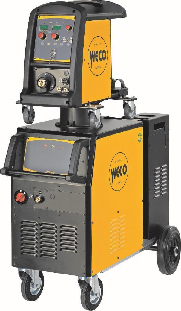
4 1 INTRODUCTION IMPORTANT! This handbook must be consigned to the user prior to installation and commissioning of the unit. Read the "General prescriptions for use" handbook supplied separately from this handbook before installing and commissioning the unit. The meaning of the symbols in this manual and the associated precautionary information are given in the "General prescriptions for use. If the "General prescriptions for use" are not present, it is mandatory to request a replacement copy from the manufacturer or from your dealer. Retain these documents for future consultation. 2 FRONT PANEL KEY This symbol identifies an action that occurs automatically as a result of a previous action. This symbol identifies additional information or a reference to a different section of the manual containing the associated information. This symbol identifies a reference to a chapter of the manual. This symbol accompanies important information concerning the execution of the relevant operations. is a power source for welding. When combined with a wire feeder it can be used for MIG/MAG welding. Accessories that can be connected to the unit: wire feeding unit. liquid cooler for torches. 1: Welding power source ON/OFF switch. 2: Mains protection ON LED. This LED illuminates if an incorrect operating condition occurs: absence of a phase in the power supply line. 3: Earth welding socket. 4/14
5 0 3 REAR PANEL : Cooler power feeding connector. Voltage 230 V~ Current Output IP protection rating 0.8 A IP20 (cap open) IP66 (cap closed) WARNING! High voltage! If the socket is not connected to any devices always close the cap: presence of hazardous voltage levels! 2: Power supply transformer fuse. Type Amperage Voltage Delayed acting (T) 2 A 500 V 3: Connector of the bundle of cables for connecting the power source to the remote control device. 4: Power cable. Total length (including internal part) 4,5 m Number and cross section of wires 4 x 4,0 mm 2 Power plug type Not supplied 5: Socket for connecting the power cable between the power source and the remote control device /14
6 4 INSTALLATION WARNING! Lifting and positioning Read the warnings highlighted by the following symbols in the General prescriptions for use. 4.1 UNIT ASSEMBLY 1. Fit the front swivel wheels with the supplied screws. 2. Screw the fixed rear wheels to the studs in the base of the unit and secure them with the supplied nuts. 4.2 CONNECTIONS TO THE ELECTRICAL MAINS NETWORK The characteristics of the mains power supply to which the equipment shall be connected are given in the section entitled technical data on page 8. The machine can be connected to motorgenerators provided their voltage is stabilised. Connect/disconnect the various devices with the machine switched off. 3. Mount the cooler in the relevant location. 4. Screw the cooler fixing bracket to the welding power source chassis using the supplied screws. 5. Screw the base of the cooler to the unit base using the supplied screws. 6. Connect the plug of the cooler power cable to the cooler power socket on the rear panel of the welding power source. 6/14
7 0 5 USER INTERFACE L1 L2 L3 CODE SYMBOL DESCRIPTION L1 This LED illuminates to show an anomaly in the operating conditions. For information on alarm management, please refer to the relevant section in the manual of the wire feeder. L2 L3 This LED illuminates to confirm the presence of power on the output sockets. Illuminates to show that the cooling unit pressure switch does not detect any pressure. - Check that the connection to the cooler is correct. - Check that the O/I switch is set to I and that it illuminates when the pump is running. - Check that the cooler is filled with coolant. - Check that the cooling circuit is liquid tight, notably the torch hoses and the internal connections of the cooler. 7/14
8 6 TECHNICAL DATA Model Construction standards Supply voltage Mains protection Dimensions ( L x D x H ) Weight Insulation class Protection rating Cooling Supply voltage EN EN Class A 3 x 400 V~±15 % / Hz 16 A Delayed 1110 x 530 x 750 mm 58 kg H IP23 AF 3 x 400 V~±15 % / Hz Temperature of the environment 40 C Welding mode Static characteristic MIG/MAG Work cycle 45 % 60 % 100 % Welding current 320 A 280 A 230 A Working voltage 30.0 V 28.0 V 25.5 V Maximum input power 11.6 KVA 9.5 KVA 7.1 KVA Maximum supply current 17.0 A 13.6 A 10.2 A Maximum effective current 11.4 A 10.5 A 10.2 A Open-circuit voltage (U0) Zmax 50 V This equipment complies with IEC provided that the maximum permissible system impedance is less than or equal to 83 mω at the interface point between the user's supply and the public system. It is the responsibility of the installer or user of the equipment to ensure, by consultation with the distribution network operator if necessary, that the equipment is connected only to a supply with maximum permissible system impedance less than or equal to 83 mω. 8/14
9 0 7 SPARE PARTS 7.1 PIONEER 321 MSR 9/14
10 N CODE DESCRIPTION RIGHT HANDLE FRONT HANDLE FRONT PANEL LABEL FIXED SOCKET 400 A LOGIC BOARD PLATE LEFT HANDLE LED BOARD CAP Ø= FRONT PLATE (1) THREE-POLE SWITCH FRONT PLATE (2) LED WIRING FRONT PLATE (3) PANEL SUPPORT PLATE FRONT LOGIC BOARD COVER PLATE HEAT SINK MOTOR SUPPORT PLATE (1) LOWER COVER FANS SUPPORT PLATE CASTOR BASE SLIDE METAL PLATE WHEEL FIXING PLATE FIXED WHEEL WASHER M SPLIT PIN RIGHT COVER PANEL FAN REAR PLATE (1) GAS BOTTLE SUPPORT PLATE NEOPRENE CABLE CABLE BUNDLE SUPPORT PLATE (1) CABLE BUNDLE SUPPORT PLATE (2) COOLING UNIT SUPPORT PLATE BELT FOR GAS BOTTLE C.U. POWER CONNECTOR CAP C.U. POWER SUPPLY WIRING CAP Ø= INTERNAL PLATE UPPER COVER WF SUPPORT FUSE HOLDER CAP FUSE HOLDER REAR PLATE (2) CABLE CLAMP REMOTE LOGIC CABLE FIXED SOCKET 400 A POWER TRANSFORMER TRANSFORMER SUPPORT PLATE OUTPUT INDUCTOR TUNNEL HOUSING (1) BOARDS SUPPORT WIRE FEEDER COVER PLATE LOGIC BOARD AUXILIARY TRANSFORMER PRIMARY CAPACITOR BOARD DIODES-SOCKET COPPER BRACKET MAINS FILTER BOARD HALL EFFECT SENSOR TORCH HOLDER LEFT COVER PANEL COVER PANEL SUPPORT PLATE INTERNAL FRAMEWORKS POWER BOARD SNUBBER BOARD DIODE-DIODE BRACKET THREE PHASE BRIDGE RECTIFIER THERMAL CUT-OUT 75 C ISOTOP DIODE POWER SUPPLY CONTROL BOARD FAN AND C.U. CONTROL BOARD 10/14
11 0 8 ELECTRICAL DIAGRAM 11/14
12 12/14 F +32 (0)
13 0 8.1 PIONEER 321 MSR WF-107 CABLE 13/14
14 14/14 F +32 (0)
Pioneer 321 MKS. Instruction manual
 WECO srl Via S. Antonio, 22 - BELVEDERE 36056 TEZZE SUL BRENTA (VICENZA) ITALY Tel.+39 0424 561943 Fax +39 0424 561944 www.weco.it - E-mail info@weco.it GB Instruction manual 2/32 0 1 INTRODUCTION... 4
Mig 410, Mig 510. Spare parts list. Edition Valid for serial no. 627-xxx-xxxx, 122-xxx-xxxx
 Spare parts list Edition 20120117 Valid for serial no. 627-xxx-xxxx, 122-xxx-xxxx Ordering no. Product 0349 302 408 Origo Mig 410, 400-415 V 3~50Hz 0349 302 713 Origo Mig 410, 230/400-415/500V 3~50Hz;
Mig 3001i. Spare parts list. Edition Valid for serial no. 833-xxx-xxx, 950-xxx-xxxx, 039-xxx-xxxx
 Spare parts list Edition 20110715 Valid for serial no. 833-xxx-xxx, 950-xxx-xxxx, 039-xxx-xxxx Ordering no. Product 0459 740 882 Origo Mig 3001i 0459 740 883 Origo Mig 3001iw 0459 740 884 Origo Mig 3001i
Mig 4001i. Spare parts list. Edition Valid for serial no. 833 xxx xxx, 852 xxx xxx
 Spare parts list Edition 100125 Valid for serial no. 833 xxx xxx, 852 xxx xxx Ordering no. Product 0460 455 882 Origo Mig 4001i 0460 455 883 Origo Mig 4001iw with cooling unit 0460 455 884 Origo Mig 4001i
MERKLE OptiMIG. The MIG/MAG Industrial series! MIG/ MAG
 MERKLE OptiMIG. The MIG/MAG Industrial series! MIG/ MAG www.merkle.de MIG/ MAG Merkle OptiMIG MIG/MAG series OptiMIG The series OptiMIG 350/450/550 consists of step controlled MIG/MAG welding units from
Mig 5000i, Mig U5000i 400 V version. Spare parts list. Edition Valid for serial no. 803 xxx xxxx,
 Spare parts list Edition 091130 Valid for serial no. 803 xxx xxxx, Ordering no. Product 0459 230 880 Mig 5000i 400 V version 0459 230 881 Mig 5000i with water cooling unit 400 V version 0459 230 882 Mig
IM /2017 REV01 POWER WAVE S700 CE
 POWER WAVE S700 CE IM2061 09/2017 REV01 Spare Parts... 1 POWER WAVE S700 CE... 1 Miscellaneous Items... 1 POWER WAVE S700 CE Assemblies overview... 2 Figure 1: Case Front Assembly... 3 Figure 2: Lower
Valid for serial no. 322 xxx xxxx, 334 xxx xxxx, 347 xxx xxxx, 445 xxx xxxx, 524 xxx xxxx, 620 xxx xxx, 640 xxx xxxx, 802 xxx xxxx
 Spare parts list Edition 090525 Valid for serial no. 322 xxx xxxx, 334 xxx xxxx, 347 xxx xxxx, 445 xxx xxxx, 524 xxx xxxx, 620 xxx xxx, 640 xxx xxxx, 802 xxx xxxx The AristoMig power source is renamed:
Mig 4004i, 5004i, Origo Mig 4004i. Spare parts list. Edition Valid for serial no. 145-xxx-xxxx, 211-xxx-xxxx
 Spare parts list Edition 20120828 par-01 Valid for serial no. 145-xxx-xxxx, 211-xxx-xxxx Ordering no. Product 0465 154 880 Mig 4004i 0465 155 880 Mig 5004i 0465 152 880 Origo TM Mig 4004i, with A44 control
PARTS LIST FOR VIPER VIPER
 P-336 P-336 PARTS LIST FOR P-336-A P-336-A ILLUSTRATION OF SUB-ASSEMBLIES 6 3 1 5 2 4 P-336-A.1 P-336-A.1 For Codes: 10597 to 10635 Do Not use this Parts List for a machine if its code number is not listed.
Mig 4000i, Mig U4000i. Spare parts list. Edition Valid for serial no xxx -xxxx
 Spare parts list Edition 080215 Valid for serial no. 803 -xxx -xxxx Ordering no. Product 0458 625 880 Mig 4000i 0458 625 881 Mig 4000i with cooling unit 0458 625 890 Mig 4000i with cooling unit and flow
Valid for serial no. 050 xxx xxxx, 105 xxx xxxx, 347 xxx xxxx, 445 xxx xxxx, 524 xxx xxxx, 620 xxx xxxx, 640 xxx xxxx, 802 xxx xxxx
 Spare parts list Edition 090525 Valid for serial no. 050 xxx xxxx, 105 xxx xxxx, 347 xxx xxxx, 445 xxx xxxx, 524 xxx xxxx, 620 xxx xxxx, 640 xxx xxxx, 802 xxx xxxx The AristoTig power source is renamed:
AME. Rectifier - Battery charger. Industrial applications: Key features:
 Rectifier - Battery charger AME VRLA batteries, flooded battery or Ni/Cd with output voltage from 24, 48, 110, 220 Vdc up to 150A Industrial applications: Oil&Gas (Petrochemicals Offshore, Onshore, Pipelines);
Caddy. Tig 2200i AC/DC. Instruction manual GB Valid for: serial no. 711-, 747-xxx-xxxx
 Caddy Tig 2200i AC/DC Instruction manual 0460 225 301 GB 20180920 Valid for: serial no. 711-, 747-xxx-xxxx TABLE OF CONTENTS 1 SAFETY... 4 1.1 Meaning of symbols... 4 1.2 Safety precautions... 4 2 INTRODUCTION...
Origo Mig 402cw, 402c, Mig 502cw, 502c, Mig 652cw, 652c
 Spare parts list Edition 20120123 Valid for serial no. 712, 714,715,716,725,726,743,747,748,749,751,750-xxx-xxxx Ordering no Product Notes Ser.no 0349 308 500 Origo TM Mig 402cw 400V 415V, 3~50Hz; with
Powercut Spare parts list. Edition Valid for serial no. 001-xxx-xxxx, 034-xxx-xxxx
 Spare parts list Edition 20111010 Valid for serial no. 001-xxx-xxxx, 034-xxx-xxxx Ordering no. Product 0558 007 636 Powercut 1600, 400V 0558 007 637 Powercut 1600, 400V 25ft 0558 007 237 Powercut 1600,
User Manual Rittal PMC UPS 6kVA
 User Manual Rittal PMC UPS 6kVA Germany Rittal GmbH & Co. KG Auf dem Stützelberg D-35745 Herborn Tel.: ++49-27 72-5 05-0 Fax: ++49-27 72-5 05-23 19 Internet: www.rittal.de 26 Contents 1. Introduction...
Power thyristor units. 460 series. Control of single-phase resistive and inductive loads. User Manual
 Power thyristor units 460 series Control of single-phase resistive and inductive loads User Manual Copyright Eurotherm Automation 1996 All rights reserved. All reproduction or transmission in any form
3RT14 Contactors with 3 Main Contacts
 3RT14 Contactors with 3 Main Contacts for Switching Resistive Loads Contactor Size 3RT14 46 Mechanical endurance Oper. 10 million Electrical endurance Oper. 0.5 million C-1 utilization category at I e
NERTAMATIC 450 AC/DC POWER SOURCE NO. W
 NERTAMATIC 450 AC/DC POWER SOURCE NO. W000315023 EDITION: EN Instructions for use REF.: 8695-5522 REVISION: D DS: DATE: 11-2008 NERTAMATIC 450 AC/DC -1 1- DESCRIPTION -2 NERTAMATIC 450 AC/DC 1- DESCRIPTION
2.1 Warnings & Agency Approvals Electrical Connections - Specifications Standard Wiring Configurations...2 4
 CHAPTER ELECTRICAL 2 INSTALLATION Contents of this Chapter... 2.1 Warnings & Agency Approvals..................2 2 2.1.1 Isolation..............................................2 2 2.1.2 Electrical Power
DEEP SEA ELECTRONICS PLC
 COMPLEX SOLUTIONS MADE SIMPLE. DEEP SEA ELECTRONICS PLC DSE5110 AUTOSTART CONTROL MODULE OPERATING MANUAL Deep Sea Electronics Plc Highfield House Hunmanby North Yorkshire YO14 0PH ENGLAND Sales Tel: +44
WELDING SYSTEM. Welding System. Car-O-Liner is a world leading provider of collision repair systems
 Eng E WELDING SYSTEM Welding System Car-O-Liner is a world leading provider of collision repair systems Contents Resistance Spot Welder 4 Resistance Spot Welder CR500 DA 4 Resistance Spot Welder CR510
Installation manual. Modbus Interface DIII EKMBDXA7V1. Installation manual Modbus Interface DIII. English
 Modbus Interface DIII EKMBDXA7V1 Modbus Interface DIII English 379 mm 0 C 100 mm 50 mm 50 mm 40 mm 87 mm 300 mm IP X0 50 mm 60 C 365 mm 124 mm Max. 100 mm Min. 1 2 3 1 www.daikineurope.com/support-and-manuals/product-information/
INTER PLANT STANDARD STEEL INDUSTRY SPECIFICATION FOR STATIC EXCITATION CONVERTORS FOR SYNCHRONOUS MOTORS (FIRST REVISION)
") INTER PLANT STANDARD STEEL INDUSTRY I P S S SPECIFICATION FOR STATIC EXCITATION CONVERTORS FOR SYNCHRONOUS MOTORS (FIRST REVISION) Corresponding IS does not exist IPSS: 1-10-036-12 0 FOREWORD 0.1 This
INTER PLANT STANDARD STEEL INDUSTRY I P S S SPECIFICATION FOR STATIC EXCITATION CONVERTORS FOR SYNCHRONOUS MOTORS (FIRST REVISION) Corresponding IS does not exist IPSS: 1-10-036-12 0 FOREWORD 0.1 This
Electronic Circuit Breaker ESS20-0..
 Electronic Circuit Breaker ES-0.. Description Electronic circuit breaker type ES-0.. is designed to ensure selective disconnection of individual loads in systems which are powered by a DC 4 V switch-mode
Thyristor power units TC3000. Three-phase load control. User Manual
 Thyristor power units TC3000 Three-phase load control User Manual Copyright Eurotherm Automation 1996 All rights reserved. All reproduction or transmission in any form or using any procedure (electronic
Operating manual UPS - System
 Operating manual UPS - System POWERMASTER M MIL 1000VA 7Min. BAX 3330 E UPS-Division Issued 15. August 2006 JOVYATLAS JOVYATLAS Elektrische Umformtechnik GmbH Groninger Straße 29-37 D-26789 Leer/Ostfriesland
Migmaster 250 Pro. Spare parts list. Ordering number. Validforserialno.528,607-xxx-xxxx
 Spare parts list Validforserialno.528,607-xxx-xxxx Ordering number 0349 305 430 Migmaster 250 Pro 208/230V, 1 50/60Hz 0349 307 740 Migmaster 250 Pro 208/230/460/575V, 1 50/60Hz Spare parts are to be ordered
ELECTRIC TRACTION.
 ELECTRIC TRACTION www.koncar.hr MODERNISATION ELECTRIC TRACTION VEHICLES Company KON AR - ELECTRIC VEHICLES Inc. upgrades electric locomotives, electric multiple unit and electric tramcars. Upgrading proceedings
THREE PHASE AND SINGLE PHASE ASYNCHRONOUS ELECTRIC MOTORS OPERATION AND MAINTENANCE BOOKLET Rev
 MORATTO S.R.L. Electrical Machinery I 31030 PERO DI BREDA (Treviso) Italy Via A Volta, 2 Tel. +390422904032 fax +39042290363 www. moratto.it - moratto@moratto.it THREE PHASE AND SINGLE PHASE ASYNCHRONOUS
TECHNICAL SERVICE MANUAL FOR MASTERTIG ACDC MACHINES
 TECHNICAL SERVICE MANUAL FOR MASTERTIG ACDC MACHINES TECHNICAL SERVICE MANUAL FOR MASTERTIG ACDC INTRODUCTION / GENERAL MAINTENANCE OF MASTERTIG ACDC Maintenance of the Mastertig ACDC machine would normally
Deep Sea Electronics Plc
 Deep Sea Electronics Plc 5120 AUTOMATIC MAINS FAILURE MODULE OPERATING MANUAL Author: Anthony Manton Deep Sea Electronics Plc Highfield House Hunmanby North Yorkshire YO14 0PH England Tel: +44 (0) 1723
Equipment model: auxiliary control. Pack Cat.Nos 10/16 A V± P + T shuttered module module
 transformers and buzzers and bells socket outlets and special supports 042 25 042 52 041 07 042 80 042 85 Pack Cat.Nos Bell transformers dconform to IEC / EN 61558-2-8 Protected against overloads and short
Professional Wireless Products
 Page 1 of 6 093115 Communications Power Supply and Battery Management Controller Page 2 of 6 1.0 Introduction The 093115 is a 13.8 volt 15amp transformer isolated switch mode down converter designed to
HIGHLIGHTS. TIG Welding Machine for the Professional Welder
 HIGHLIGHTS TIG Welding Machine for the Professional Welder HF ignition or Liftarc Infinitely adjustable: Welding current (5A to 160A) Down-Slope time, gas post-flow time Gas pre-flow time 0,2sec. (fixed)
N Daily Weekly Monthly Every 3 months. Every 6 months 1 Remove any materials not related
 MV / LV cabins maintenance The operation and maintenance of the cabins are meant to ensure high reliability (i.e. the early detection of anomalies, the failure prevention and monitoring functional) and
WELD THE WORLD Product Range 11_2015 English
 WELD THE WORLD Product Range 11_2015 English Weco has been producing and selling for 15 years welding machines. All our welding machines are 100 % in Europe (North of Italy) produced. A wide range of welding
Control Circuit Protection
 Contents 5SJ4 Branch Circuit Protectors 5SY4 Supplementary Protectors 5SY6 Supplementary Protectors 16/19 5SJ4 Page Selection and ordering data 1-pole up to 63A 16/4 1-pole, 2-pole, 16/5 3-pole, 240VAC
Air Circuit Breakers
 Siemens AG 203 /2 Introduction 3WL air circuit breakers/ non-automatic air circuit breakers up to 6300 A (AC), IEC /8 Introduction /9 3-pole, fixed-mounted versions /6 3-pole, withdrawable versions /23
ATyS S - ATyS d S Remotely operated Transfer Switching Equipment from 40 to 125 A
 Transfer switches The solution for > Genset < 90 kva > Heating systems > Climate control > Ventilation systems > Telecommunications atys-s_018_a Strong points Function products are 4 pole remotely operated
RS/M SERIES. Modulating Gas Burners FIRING RATES
 The RS/M burners series covers a firing range from 45 to 2650 kw, and it has been designed for use in low or medium temperature hot water boilers, hot air or steam boilers, diathermic oil boilers. Operation
10 20KVA 3Ph/1Ph KVA 3Ph / 3Ph
 VEGA INDUSTRIAL UNINTERRUPTIBLE POWER SUPPLY 10 20KVA 3Ph/1Ph 10 120KVA 3Ph / 3Ph - 6 pulse SCR rectifier - IGBT inverter - Power output transformer - Low and stable ripple on battery for the highest battery
Chargestar T26 / T45. Please read and fully understand the instructions in this manual before operation. Keep this manual safe for future reference
 Please dispose of packaging for the product in a responsible manner. It is suitable for recycling. Help to protect the environment, take the packaging to the local amenity tip and place into the appropriate
INSTRUCTIONS INSTALLATION OF LOAD-SHARE TERMINALS FOR VLT DRIVES
 INSTRUCTIONS INSTALLATION OF LOAD-SHARE TERMINALS FOR VLT DRIVES This instruction sheet is for the field installation of load-share terminals for the VLT series drives frames D1, D2, D3 and D4. Kit Contents
PPS20 COMMUNICATIONS POWER SUPPLY AND BATTERY MANAGEMENT SYSTEM
 PPS20 COMMUNICATIONS POWER SUPPLY AND BATTERY MANAGEMENT SYSTEM 2 Table of Contents Introduction:... 3 1.0: Operation Principles:... 3 1.1: Stand alone supply... 3 1.2: Backed up supply:... 3 1.3: Battery
Operating Instructions Bedienungsanleitung Mode d emploi EWB EWB
 Operating Instructions Bedienungsanleitung Mode d emploi DW 400 EWB 400 575 EWB 400 575 800 www.bron-kobold.com Operating instructions EWB 400.575 EWB 400.575.800 Before use Please read all the information
EX-REPAIR AND MAINTENANCE RECEPTACLES
 EX-REPAIR AND MAINTENANCE RECEPTACLES A 3 A plugs and receptacles plastic version for zones, 2, 2 and 22 For maintenance, repair and upgrading work, appliances such as drills, welding transformers, hand
AC/DC FFE converter power module
 Sheet 1 PRODUCT DESCRIPTION The converter series FFE (Fundamental Front End) consists of a three-phase IGBT bridge working at mains frequency and works as rectifier/regenerative bridge allowing the flow
LV Capacitor CLMD03 Power Module Instruction manual
 LV Capacitor CLMD03 Power Module Instruction manual Table of Contents 1 Safety... 3 2 Upon reception... 3 2.1 Inspection on reception... 3 2.2 Storage- transportation handling... 3 3 Hardware Description...
MMA welding. Minarc Evo 46 Minarc Master MLS 50 FastMig KMS 400 AS 52 KempGouge 54
 44 MMA welding MMA welding Minarc Evo 46 Minarc 220 48 Master MLS 50 FastMig KMS 400 AS 52 KempGouge 54 Compact, lightweight and capable. Kemppi MMA equipment meets professional welding demands in every
1 T835 Installation. 1.2 Rack Wiring. 1.1 Rack Mounting
 M0-00 T Installation F. T Installation. Rack Mounting The T receiver is designed for use in a standard mm rack frame using a Tait T00 Series II guide. The guide is securely mounted to the rack frame with
Air Circuit Breakers
 Siemens AG 204 /2 Introduction 3WL air circuit breakers/ non-automatic air circuit breakers up to 6300 A (AC), IEC /8 Introduction /9 3-pole, fixed-mounted versions /6 3-pole, withdrawable versions /23
Stereo Power Amplifier
 4-569-998-12(1) Stereo Power Amplifier Operating Instructions GB For customers in the United States: The warranty for this product is included in this manual (page 12). Owner s Record The model and serial
Isolation Transformer for Medical Applications
 User Instructions Isolation Transformer for Medical Applications Type: Isolation Transformers REOMED 300VA; REOMED 600VA; REOMED 1000VA REO (UK) Limited Units 2 4 Callow Hill Road, Craven Arms Business
EPS/ELA-Series User Manual EPS/ELA 250W
 EPS/ELA-Series User Manual EPS/ELA 250W EPS Stromversorgung GmbH Tel: +49 (0)821 570451 0 Index 3 Page: 1 Table of contents: Page 1. Features of ELA-Series... 3 1.1 Basic Functions... 3 1.2 Options...
EUROTHERM ONTROLS. Two phase thyristor power switches. Product data
 TC2000 TC2001 EUROTHERM ONTROLS Two phase thyristor power switches Product data TC2000 TC2001 Thyristor power switches Compact, two phase thyristor power switches for electrical heating applications from
VARIABLE FREQUENCY DRIVES
 262923 VARIABLE FREQUENCY DRIVES PART 1: GENERAL 1.01 SUMMARY A. Section Includes: 1. Variable Frequency Drives (VFD) B. Related Sections: 1. Section 230000 - Basic HVAC Requirements 2. Section 230900
KEMPPI K5 WELDING EQUIPMENT. MinarcMig Evo 200 ULTIMATE ENERGY PERFORMANCE WITH PORTABLE COMFORT
 KEMPPI K5 WELDING EQUIPMENT MinarcMig Evo 200 ULTIMATE ENERGY PERFORMANCE WITH PORTABLE COMFORT 6.04.2018 MinarcMig Evo 200 EASY MIG/MAG WELDING FOR THE MOBILE WELDER MinarcMig Evo 200 is a portable MIG/MAG
Illustrated Parts List for GPU-400
 Illustrated Parts List for GPU-400 Series 500082-4xx 28.5 Volts, 400 Amps Section 1 Illustrated Parts List 1) Explanation of Parts List Arrangement The parts list is arranged so that the illustration will
Wilo-Control SC-Fire Jockey
 Pioneering for You Wilo-Control SC-Fire Jockey de en fr Einbau- und Betriebsanleitung Installation and operating instructions Notice de montage et de mise en service nl Inbouw- en bedieningsvoorschriften
B BASIC HEAT TREATMENT CONSOLE
 Maritime Stress PO Box 2898, 30 Estates Road Dartmouth, NS, B2W 4Y2, Canada Toll Free: 1-877-468-1781 Phone: (902) 468-7873 Fax: (902) 468-2304 Website: E-mail: info@maritimestress.com OPERATION MANUAL
M A N U A L. Field Current Controller F2.2
 M A N U A L Field Current Controller F2.2 Industrie Elektronik G m b H Hans-Paul-Kaysser-Straße 1 71397 Leutenbach Nellmersbach Tel.: 07195 / 92 83 0 Fax: 07195 / 92 83 129 info@unitek-online.de www.unitek-online.de
& HIGH CURRENT DC POWER SUPPLIES INSTRUCTION MANUAL
 72-6850 & 72-6852 HIGH CURRENT DC POWER SUPPLIES INSTRUCTION MANUAL Table of Contents Introduction 2 Specification 2 Safety 4 EMC 5 Installation 6 Connections 6 Operation 7 Maintenance and Repair 8 www.tenma.com
DEVICE STATE/BYPASSED FAILURE OVERLOAD
 Technical specifications Type 5. 7. Control electronics Rated values Terminal Rated control supply voltage A1A2 V AC 115 230 115 230 Tolerance % -15+10-15+10 Rated control supply STANDBY ma 15 15 Rated
3VF3 to 3VF8 Circuit-Breakers
 3VF3 to 3VF8 Circuit-Breakers Accessories Operating mechanisms For other s for 3VF3 with knob Rotary drive, complete, scope of supply Cubicle door for 3VF6 Motor operating mechanism for 3VF3 Motor operating
DEEP SEA ELECTRONICS PLC
 COMPLEX SOLUTIONS MADE SIMPLE. DEEP SEA ELECTRONICS PLC DSE710 AUTOSTART CONTROL MODULE OPERATING MANUAL Deep Sea Electronics Plc Highfield House Hunmanby North Yorkshire YO14 0PH ENGLAND Sales Tel: +44
Power factor correction Static switching units (Three phase).
.") Power factor correction Static switching units (Three phase). Automatic capacitor banks with static system. JK JAKI JK3PSZT-XXXXX Automatic capacitor banks with static system. Introduction Selection table
Power factor correction Static switching units (Three phase). Automatic capacitor banks with static system. JK JAKI JK3PSZT-XXXXX Automatic capacitor banks with static system. Introduction Selection table
Measurements are expressed in millimeters.
 T-Rex user manual Measurements are expressed in millimeters. 1 Lamp access 2 Focus adjustment 3 Mounting bracket 4 Swivel locks 5 Clamp hole 6 Air vent 190 285 7 AC input & main fuse 8 Microphone 490 164
Film-Tech. The information contained in this Adobe Acrobat pdf file is provided at your own risk and good judgment.
 Film-Tech The information contained in this Adobe Acrobat pdf file is provided at your own risk and good judgment. These manuals are designed to facilitate the exchange of information related to cinema
SECTION 4 ELECTRIC MOTORS UNIT 17: TYPES OF ELECTRIC MOTORS UNIT OBJECTIVES UNIT OBJECTIVES 3/21/2012
 SECTION 4 ELECTRIC MOTORS UNIT 17: TYPES OF ELECTRIC MOTORS UNIT OBJECTIVES After studying this unit, the reader should be able to Describe the different types of open single-phase motors used to drive
Battery Power Inverters
 Battery Power Inverters Renogy 500W 1000W 2000W Pure Sine Wave Inverter Manual 2775 E. Philadelphia St., Ontario, CA 91761 1-800-330-8678 1 Version 1.4 Important Safety Instructions Please save these instructions.
BATTERY BOOSTERS / CHARGERS BC120N BC130N BC210N BC320E BC410E BC520N
 BATTERY BOOSTERS / CHARGERS BC120N BC130N BC210N BC320E BC410E BC520N OPERATING INSTRUCTIONS 1106 SPECIFICATIONS MODEL 120N 130N 210N 320E 410E 520N MAX CHARGE (AMPS) 15 15 25 35 35 50 MAX BOOST (AMPS)
Origo TM Mig630twMAGMA,Mig630tMAGMA. Spare parts list. Ordering number. Validforserialno.635-xxx-xxxx
 Spare parts list Validforserialno.635-xxx-xxxx Ordering number 0349310100 Origo TM Mig630twMAGMA 230/400--415/500V,3 50Hz; 230/400--460/550V, 3 60Hz 0349310110 Origo TM Mig630tMAGMA 230/400--415/500V,3
ATyS d M Remotely operated Transfer Switching Equipment from 40 to 160 A
 ATyS d M Remotely operated Transfer Switching Equipment Transfer switches new The solution for > Applications with an external ATS/AMF controller > Building Management Systems (BMS) atys-md_002_b_1_cat
American Traction Systems. DC Bus Capacitorss. Total. Dual Chopper Module. Dual. Inverter. 750kW. 750kW Generator Module. Module
 EFFECTIVE DATE JULY 28 204 OF 8 Dual Hybrid Ship Propulsion System 750V BUS Generator Generator Propulsion Propulsion Bus Capacitorss 50,000µF Total Traction Inverter Dual Inverterr e Power Inverter L
Vistop TM isolating switches 63 to 160A
 DX 3 - IS main switches 16 to 125A Vistop TM isolating switches 63 to 160A 225 15 225 18 4 064 00 4 064 59 Pack Cat. No. Main switches AC 22 A category as per EN607-3 Grey handle Accept 1 signalling auxiliary
DEEP SEA ELECTRONICS PLC
 COMPLEX SOLUTIONS MADE SIMPLE DEEP SEA ELECTRONICS PLC DSE704 AUTOSTART CONTROL MODULE OPERATING MANUAL 057-042 704 Operating Instructions Issue 2.1 18/06/2007 11:27:00 JR - 1 - Deep Sea Electronics Plc
Observe all necessary safety precautions when controlling the soft starter remotely. Alert personnel that machinery may start without warning.
 Introduction OPERATING INSTRUCTIONS: MCD REMOTE OPERATOR Order Codes: 175G94 (for MCD 2) 175G361 + 175G9 (for MCD 5) 175G361 (for MCD 3) 1. Introduction 1.1. Important User Information Observe all necessary
World Class Power Solutions. Rectifiers. For Stationary Battery Systems in Nuclear Power Plants
 World Class Power Solutions Rectifiers For Stationary Battery Systems in Nuclear Power Plants General 2 1.1 Application Electronically controlled rectifier assemblies are used in conjunction with suitable
Miniature Circuit-Breakers (MCBs)
") Product Overview Miniature Circuit-Breakers (MCBs) Design Tripping characteristics Rated current I n Rated breaking capacity Power supply company product range 5SP3 E 16 - A Standard product range 5SQ2
Product Overview Miniature Circuit-Breakers (MCBs) Design Tripping characteristics Rated current I n Rated breaking capacity Power supply company product range 5SP3 E 16 - A Standard product range 5SQ2
5220 AUTOMATIC MAINS FAILURE MODULE OPERATING MANUAL
 5220 AUTOMATIC MAINS FAILURE MODULE OPERATING MANUAL > Section DSE Model 5220 Automatic Mains Failure & Instrumentation System Operators Manual TABLE OF CONTENTS
R5000/4000 CV INSTRUCTION MANUAL. Important Information. Description. Processes. Constant Voltage Power Source
 R5000/4000 CV Description Constant Voltage Power Source Processes Important Information All persons authorised to use, repair or service the R4000/R5000 Inverter welding unit, should read the section on
Whad 0.8, 1, 1.5 kva. Manuel d installation Installation manual. Part. LE05733AA-07/12-01 GF
 Manuel d installation Installation manual Part. LE05733AA-07/12-01 GF Index 1 Introduction 18 2 Conditions for use 19 3 Installation 20 4 Visual and acoustic warning signals 22 5 ups diagnostic software
DGP-25 MF. 1 / Genset general decription. > Open genset with automatic start-up, control card allows automatic, manual or signal start-up.
 Measures: L : 1500 mm H : 1275 mm W: 800 mm H Weight: 550 Kg W L Hz 50 Hz V 230 V Water cooled Diesel illustrative image. 1500 r.p.m Opened CE Conformity 1 / Genset general decription Engine Alternator
DEEP SEA ELECTRONICS PLC
 COMPLEX SOLUTIONS MADE SIMPLE DEEP SEA ELECTRONICS PLC DSE720 AUTOSTART CONTROL MODULE OPERATING MANUAL http://bestgenerator.spb.ru/?page_id=6765 Deep Sea Electronics Plc Highfield House Hunmanby North
IB IL 24 PWR IN/F-D IB IL 24 PWR IN/F-D-PAC
 IB IL 24 PWR IN/F-D IB IL 24 PWR IN/F-D-PAC Inline Power Terminal With Fuse and Diagnostics Data Sheet 5569C 02/2003 # # $ ' ) The IB IL 24 PWR IN/F-D and IB IL 24 PWR IN/F-D-PAC only differ in the scope
BETA Switching Switches and Light Indicators
 Siemens AG 2008 BETA Switching /2 Product overview /3 5TE8 control switches / 5TE4 pushbuttons /2 5TE5 light indicators /5 5TE8 ON/OFF switches /22 5TE9 busbars /24 5TE switch disconnectors Siemens ET
SECTION V SWITCHBOARD I 4 Engine/Gen Control Cubicles II 1 Synchronizing System III 1 Ground Detection Network IV 1 600V Feeder Section V 2
 SECTION 1. 600V SWITCHBOARD I 4 Engine/Gen Control Cubicles II 1 Synchronizing System III 1 Ground Detection Network IV 1 600V Feeder Section V 2 Soft Starters SECTION 2. LIQUID COOLED VFD I 3 Liquid Cooled
Overcurrent releases - description, specifications, characteristics specifications specifications description...
 BA5*37 COMMERCIAL INFORMATION Type designation specification for ordering...68 (design and circuit breaker and switch-disconnector accessories selection, circuit breaker rated current selection) Connecting
MGE TM Galaxy TM 7000 GFC
 MGE TM Galaxy TM 7000 GFC Grid Frequency Converter (GFC) for Shore Connection solution 500 kva Performance 3 Phase Power Protection with high adaptability to meet the unique requirements of Shore Connection
RENEWAL PARTS Supersedes: RP4 (1012) Form RP4 (813)
 Form RP4 (813)") VARIABLE SPEED DRIVE RENEWAL PARTS Supersedes: 160.00-RP4 (1012) Form 160.00-RP4 (813) 292 HP 50 HZ, 400VAC (P/N 371-03700-XXX) 351 HP 60 HZ, 460VAC (P/N 371-02767-XXX) 419 HP 50 HZ, 400VAC (P/N 371-03789-XXX)
VARIABLE SPEED DRIVE RENEWAL PARTS Supersedes: 160.00-RP4 (1012) Form 160.00-RP4 (813) 292 HP 50 HZ, 400VAC (P/N 371-03700-XXX) 351 HP 60 HZ, 460VAC (P/N 371-02767-XXX) 419 HP 50 HZ, 400VAC (P/N 371-03789-XXX)
USERS MANUAL MCD REMOTE OPERATOR
 USERS MANUAL MCD REMOTE OPERATOR Order Code: 175G9004, 175G3061 Contents Contents Introduction...2 Important User Information...2 General Description...2 Symbols Used in this Manual...2 Installation...3
DRY TYPE TRANSFORMERS
 DRY TYPE Trafotek transformers are made to meet customer requirements in demanding applications. We are specially focused on manufacturing transformers for different types of frequency converters and special
MODEL 520 REMOTE START ENGINE MANAGEMENT SYSTEM
 MODEL 520 REMOTE START ENGINE MANAGEMENT SYSTEM DSE 520 ISSUE 4 4/4/02 MR 1 TABLE OF CONTENTS Section Page INTRODUCTION... 4 CLARIFICATION OF NOTATION USED WITHIN THIS PUBLICATION.... 4 1. OPERATION...
Models: EP EP EP EP EP EP USER MANUAL ENGLISH
 P R O F E S S I O N A L P O W E R A M P L I F I E R Models: EP - 300 EP - 500 EP - 800 EP - 1000 EP - 1300 EP - 1800 USER MANUAL ENGLISH WARNING FOR YOUR OWN SAFETY, PLEASE READ THIS USER MANUAL CAREFULLY
1 / Genset general description
 Measures: L : 1350 mm H : 1200 mm W: 720 mm H Weight: 410 kg W L Hz 50Hz V 400/230V Water cooled Diesel 1500 r.p.m. Open Illustrative image. CE Conformity 1 / Genset general description Engine KOHLER KDW
Mass Sine 24/10000 Mass Sine 24/15000
 USERS- AND INSTALLATION MANUAL Mass Sine 24/10000 Mass Sine 24/15000 Modular high power inverter system MASTERVOLT Snijdersbergweg 93, 1105 AN Amsterdam The Netherlands ENGLISH: PAGE 1 Tel.: +31-20-342
Electronic Circuit Breaker ESS20
 Electronic Circuit Breaker ESS20 Description Electronic circuit breaker type ESS20 is designed to ensure selective disconnection of individual loads in systems which are powered by a DC 24 V switch-mode
Actuators for Fire Protection Dampers
 4 620 OpenAir TM Actuators for Fire Protection Dampers GNA126.1E/T. GNA326.1E/T. Rotary version, 2-position control, with spring return and ready connected temperature monitoring unit, / DC 24 48 V / AC