XCITE Owner s Manual. Reso-not TM Damping System XCITE LS Inertial Linear Excitation System
|
|
|
- Valerie Gordon
- 5 years ago
- Views:
Transcription
1 Reso-not TM Damping System Owner s Manual LS Inertial Linear Excitation System ES Inertial Mass Exciter Head 1104-MOD2 Master Controller 1201B Hydraulic Power Supply Xcite Systems Corporation 675 Cincinnati RDS Batavia - 1 Pike Cincinnati, Ohio Tel: (239) Fax: (239) info@xcitesystems.com Web:
2 Preface Copyright 1997 Xcite Systems Corporation This document contains proprietary information of Xcite Systems Corporation and is tendered subject to the conditions that the information (a) be retained in confidence (b) not be reproduced or copied in whole or in part and (c) not be used or incorporated into any product except under an express written agreement with Xcite Systems Corporation. P - 2
3 Preface Table of Contents 1. Warranty... P Xcite Products... P Third Party Hardware Products... P IMPORTANT LIMITATIONS... P NOTICE OF LIMITED WARRANTY... P-8 2. Receiving... P Receiving Inspection Procedure... P Shipping Container... P Inertial Mass Exciter System Setup and Operation 1. Introduction...S&O-1 2. System Description...S&O-1 3. Setup Procedure...S&O Mounting the ES to the Test Structure... S&O B or 1301B Hydraulic Power Supply Commissioning Procedure... S&O Hydraulic Hookup... S&O Cable Hookup... S&O-4 4. Operation Procedure...S&O Switch Settings... S&O-4 5. Shutdown Procedures...S&O-5 6. Troubleshooting Guide...S&O-6 7. Storage Instructions...S&O-7 ES Inertial Mass Exciter Head 1. Introduction... EH-1 2. Description... EH Actuator Assembly...EH Head Assembly... EH-2 3. Specifications... EH B Hydraulic Power Supply 1. Introduction... HPS-1 2. Commissioning Procedure... HPS Initial Setup of Hydraulic Power Supply... HPS Starting the Hydraulic Power Supply... HPS Hydraulic Hookup... HPS Cable Hookup... HPS-3 P - 3
4 Preface 3. Theory of Operation... HPS Circuit Description (Hydraulic)... HPS Circuit Description (Electric)...HPS-4 4. Description... HPS Major Components... HPS Control Components... HPS Monitoring Devices... HPS-6 5. Care and Maintenance... HPS Operating Care... HPS Maintenance... HPS-8 6. Troubleshooting... HPS Unit Overheats... HPS Pump De-energizes... HPS-8 7. Specifications... HPS-9 8. Drawings... HPS-9 Master Controller 1. Introduction... MC-1 2. Theory of Operation... MC Configurations... MC Single Loop... MC Dual Loop... MC-1 3. Description... MC Front Panel... MC Static Signal Level Meter (M-101)...MC Static Set Point (R301)... MC Dynamic Signal Level Meter (M-102)...MC Dynamic Set Point (R303)... MC Excitation Mode (SW304)... MC Interlock (L301)... MC Dither - ON/ OFF (SW308)... MC Static Set Point (R301)... MC Static Gain... MC Load Cell... MC Calibrate/ Operate (SW307)... MC Power (SW301)... MC Pump... MC Dynamic Set Point (R303)...MC Frequency Range - HIGH/ LOW (SW309)...MC Rear Panel... MC Exciter Head (J305)... MC Displacement (J311)... MC-6 P - 4
5 Preface Calibration Resistor (J304)... MC Static Preload (SW310)... MC Interlock (J306)...MC Power (J307)... MC Fuse (F301)... MC Program Input (J308)...MC Controlled Variable - Static...MC Controlled Variable - Dynamic...MC Compression Output (J310)... MC Standby Level (R313)...MC Load Cell Output (J303)... MC Power Amp - INT/ EXT (SW312)... MC Power Amp - Input (J312)...MC EXT Set Point - Static (J313)... MC EXT Set Point - Dynamic (J314)... MC Operation... MC Concept of Operation... MC System Interconnection... MC Operation - Force Control...MC Set Controls... MC Depress the Power Switch... MC Adjust Load Cell... MC Depress Pump Start Button... MC Operation - Displacement Control...MC Set Controls... MC Operation - External Variable...MC Computer Control - External Set Points (Static and Dynamic)...MC Theory of Operation... MC Circuit Descriptions... MC VR101 (Voltage Regulator)... MC SW310 (Preload Switch)... MC A109 (Amplifier)... MC A104 and A105 (Static Control Loop)... MC A401 and A402 (Dynamic Loop)... MC A107 (Inverter Buffer)... MC A106 and U103 (Peak Detector Circuit)... MC Specifications... MC Drawings... MC Parts List... MC Calibration... MC Equipment Needed... MC Master Controller... MC-27 P - 5
6 Preface Meter Zero Adjustments... MC /-15 Volt Supply Check... MC /- 60 Volt Supply Verification...MC Load Cell Excitation Voltage Verification... MC Master Controller Board Calibration Procedure... MC Master Controller Board Calibration Procedure... MC Master Controller Board Calibration Procedure... MC Exciter Head Calibration Procedure... MC Load Cell Amplifier Calibration... MC Static Loop Gain Calibration... MC Static Set Point Level Calibration... MC High Frequency Dynamic Level Calibration... MC Low Frequency Dynamic Calibration... MC Displacement Calibration Procedure... MC LVDT Symmetry Verification and Adjustment... MC Displacement Zero Calibration... MC Displacement Scaling Calibration... MC Final External Static Control Variable Calibration... MC Dynamic Displacement Calibration... MC External Static and Dynamic Set Point Calibration... MC-46 P - 6
7 Preface 1. Warranty 1.1. Xcite Products Xcite Systems Corporation warrants that any Xcite manufactured product will conform to Xcite s written specifications applicable at the time of shipment and will be free from defects in material or workmanship for one year. During the Xcite warranty period, Xcite, or its agent, will repair or replace, at its option, any defective product when returned to the factory, freight prepaid by the buyer, and will return the product freight collect. Xcite assumes no liability for loss or damage during shipment to and from the factory. If insurance on the return shipment is required, it must be specified by the buyer Third Party Hardware Products Xcite will transfer the original manufacturer s warranty for third party hardware (not manufactured by Xcite) to the buyer. The warranty policy of those companies in effect at the time of shipment will apply to their products, and Xcite assumes no additional responsibility. Xcite will indicate on its invoice the warranty terms relevant to specific Third Party Hardware items IMPORTANT LIMITATIONS The warranty period commences upon the day of shipment from Xcite without respect to any acceptance criteria or payment provisions in any particular contract The warranty period does not apply to normal wear items or to damage caused by abuse, neglect or accident Xcite s responsibility is limited to the above obligations, and Xcite cannot be held responsible for special or consequential or other damages. ALL OTHER EXPRESS OR IMPLIED WARRANTIES, INCLUDING MERCHANTABILITY AND FITNESS FOR PURPOSE, ARE EXCLUDED. P - 7
8 Preface 1.4. NOTICE OF LIMITED WARRANTY THE FOLLOWING ITEM(S) INCLUDED IN THIS PRODUCT OR SYS- TEM ARE EXCLUDED FROM OUR ONE YEAR WARRANTY BECAUSE THEY ARE NORMAL WEAR ITEMS: 2. Receiving 1) All system seals 2) Servovalve* *The servovalve used on this system will be damaged if any particle(s) larger than 10 microns are permitted to enter the valve. Extreme care should be exercised when the hydraulic hoses are connected to ensure no foreign particles enter the connections. It is recommended to always wipe the hydraulic couplings with lint free towel before making connections. Always use the protective dust covers on the hoses (the dust covers can be connected together when operating the system). Any damage to the servovalve as a result of contamination is specifically excluded from warranty Receiving Inspection Procedure Xcite Systems Corporation products are shipped in a manner designed to protect against all normal shipping hazards. Immediately upon receipt, inspect all equipment and note any visible damage. In accordance with the instructions in this manual, test its functional operation. Keep all documents in relation to this shipment. If shipping damage is apparent, file a claim with the carrier s claim agent and send a copy to Xcite Customer Service. Be sure to include the product name, model number and serial number on all correspondence Shipping Container Shipping containers are supplied with all Xcite products. Store these containers and inserts in a dry area for possible later use. P - 8

9 Inertial Mass Exciter System Setup and Operation
10 Setup and Operation Inertial Mass Exciter System 1. Introduction The function of this system is to impart a controlled force into structures such as turbine and generator bearing pedestals, equipment foundations, buildings, etc. without requiring back-up fixturing. This inertial force generation is accomplished by a closed loop electro-hydraulic system which accelerates an inertial mass at frequencies from 4 Hz to 1000 Hz with either sine or random waveforms. The static control loop of the system utilizes a built-in Displacement Transducer (LVDT) as feedback and controls the static position of the mass while the dynamic control loop utilizes the built-in load cell as feedback to measure and control the dynamic force applied to the structure under test. 2. System Description The FTS System consists of the Xcite ES Inertial Mass Exciter Head, the Xcite 1104-Mod2 Master Controller and the Xcite 1001P Field Hydraulic Power Supply (HPS). This manual contains a section of detailed information on each of these components, and the user should familiarize himself or herself with this information before using the system. If the user has purchased the Inertial Mass Exciter Head and Master Controller without an Xcite Hydraulic Power Supply, any reference to the power supply in this manual applies to whatever source of hydraulic power the user has elected. 3. Setup Procedure 3.1. Mounting the ES to the Test Structure The ES may be mounted in any orientation but care must be taken to provide strain relief on hoses and cables if the unit is mounted at heights which would add significant loads to the hoses and cables The Exciter mounting base has four (4) English and four (4) Metric threaded holes for mounting. Using one of these sets, either directly bolt the base to the test structure or bolt an adapter plate to the base, which can then be bolted to the structure. See drawing C after page EH-4. S&O - 1

11 Setup and Operation CAUTION! Care must be taken that the Exciter is firmly and squarely attached to the structure. Any clearances or dead zones in the attachment or dynamics of any adapter plates will cause distortion of the force waveform Remove the mass holding bolts from both sides of the ES Exciter Head. The mass will not move up and down if these bolts are not removed. They are to be used for shipping purposes only. CAUTION: The mass will drop down when the last bolt is removed B or 1301B Hydraulic Power Supply Commissioning Procedure See paragraphs 2.1 and 2.2 in the 1201B Hydraulic Power Supply - Section HPS for detailed instructions on HPS commissioning Remove all packing material from inside and outside the pump cabinet Remove the main power cable from inside of cabinet Fill oil reservoir with new, clean Mobile DTE-24 hydraulic fluid (or equal). Check oil sight gage for proper oil level Connect main power cable to main electrical service. The 1201B or 1301B Hydraulic Supply is wired for 230V, 60 Hz; 460V, 60 Hz; 575V, 60 Hz, or 380V, 50 Hz, 3 phase mains. The 3 phase wire colors are Red, Black and White. Ground (Green Wire) must be connected or ground loopscwill exist in instrumentation causing 60 Hz or 50 Hz signal noise. S&O - 2
12 Setup and Operation Connect the 1104-MOD2 pump control cable (B-11921) to the hydraulic power supply and to the rear panel connector of the Master Controller Turn on the Main Power Switch (large red switch) located on the Hydraulic Power Supply Verify that the yellow PHASE CORRECT light is lit. If not, reverse the Red and Black wires at the main power connection. The pump will not start until the phase correct lamp is illuminated Thoroughly flush system before use. See paragraphs 2.1 and 2.2 in the 1201B Hydraulic Power Supply - Section HPS Hydraulic Hookup (See Drawing C ) CAUTION Do not connect Exciter Head hoses until HPS is flushed according to paragraphs 2.1 and 2.2 in the 1201B Hydraulic Power Supply - Section HPS Connect the Hydraulic Power Supply pressure and return hoses to the ES Input 3000 psi and Return hoses via the polarized quick disconnect Take care to maintain cleanliness by always attaching caps to the quick disconnects when disconnected When in doubt about hose polarity, the convention on the Hydraulic Power Supply is: Supply Pressure - Coupler Supply Return - Nipple Take care that hoses will not rub against sharp objects when pulsating. S&O - 3
13 Setup and Operation 3.4. Cable Hookup (See Drawing C ) Connect cable C to the Inertial Mass Exciter Head and connectors J-305, J-306, J-309 and J-311 of the Master Controller Connect cable B to the rear panel connector of the Master Controller and the displacement connector of the Exciter Head. 4. Operation Procedure 4.1. Switch Settings Set the switches on the back of the Master Controller to the following: CONTROLLED VARIABLE STATIC DYNAMIC STATIC PRELOAD POWER AMP EXTERNAL INTERNAL TENSION/ CW INT Set the switches on the front of the Master Controller to the following: DITHER OFF STATIC SET POINT 5.0 STATIC GAIN FIXED VARIABLE GAIN 5.0 LOAD CELL OPERATE EXCITATION MODE STANDBY/ RESET FREQUENCY HIGH (Do not use low) DYNAMIC SETPOINT Connect a 1.0 Vrms variable frequency oscillator to the Program Input J Press POWER on Master Controller. The POWER light will be illuminated Press PUMP START on the Master Controller Turn the EXCITATION MODE to STATIC. The STATIC SIGNAL LEVEL should remain at 50% since the STATIC SETPOINT is set to 5.0. If necessary, make adjustments to the SETPOINT such that the meter is reading 50% to assure that the inertial mass remains at mid-stroke. S&O - 4
14 Setup and Operation Turn EXCITATION MODE to STATIC + DYNAMIC Slowly increase the DYNAMIC SETPOINT until the desired force is monitored at the DYNAMIC SIGNAL LEVEL meter and is measured at the LOAD CELL OUTPUT BNC. The output voltage is calibrated at 250 lb/ volt System Interlock The 1104-MOD2 Master Controller is supplied with an inertial mass displacement peak detector circuit. If the inertial mass is moving more than +/-.45 inches, the system will go into interlock mode and shut off the Exciter Head and the Hydraulic Power Supply. 5. Shutdown Procedures To reset the system, place the MODE CONTROL SWITCH to standby and restart the Hydraulic Power Supply. It is also advisable to decrease the dynamic setpoint to a lower force at the specified frequency or the system will interlock again when it is restarted Turn EXCITATION MODE to STANDBY/ RESET Push PUMP STOP of the Master Controller. S&O - 5
15 Setup and Operation 6. Troubleshooting Guide Problem Static meter does not indicate mass has moved to mid-position when system is turned on in Standby/ Reset Mode. Action Check that the Hydraulic Power Supply is turned on and reading 3300 psi. See Check that all hoses and cables are connected. See 3.3. and 3.4. Verify that all Master Controller switches are in the correct position. See and Static meter does not remain at 50% indicating that the mass is remaining at mid-stroke when the mode switch is moved to Static. No force is measured at the Force Output BNC or is indicated on the Dynamic meter. Adjust the Static Set Point potentiometer so the meter is reading 50%. See Verify that the 1 V rms signal from the signal source is connected to the Program Input BNC on the back of the Master Controller. See Verify that the Dynamic Set Point potentiometer is turned up. See S&O - 6


16 Setup and Operation 7. Storage Instructions Be sure to attach the caps and plugs to all hydraulic quick disconnects to protect from contamination when not in use. When the Exciter Head will not be used for extended times, or if it is going to be shipped to another location, be sure to align the mass with the mass holding holes and insert the mass holding bolts on each side of the Exciter Head. This alignment must be accomplished with the HPS operating and STATIC control used to move the mass to its correct position. Insert the mass holding bolts as shown on both sides of the Exciter body. CAUTION: The Hydraulic Power Supply must be turned on and the mass centered to align the bolt holes. Keep the system in a clean and low humidity environment when not in use. S&O - 7
17

18 ES Inertial Mass Exciter Head
19 ES Inertial Mass Exciter Head 1. Introduction The Model ES Inertial Mass Exciter Head is a variable force exciter capable of imparting high forces to a structure without the use of auxiliary support structures. Controlled force output is produced by sinusoidally accelerating a 55 lb (25 Kg) weight through a one inch stroke. The peak output force is, therefore, equal to the peak sinusoidal acceleration of the weight times the mass (weight/ g) of the weight. The output force may be in either a horizontal or vertical direction, depending on mounting attitude chosen. A low profile, fatigue rated load cell is used to measure the actual output force at the point of application. This also serves as the feedback transducer for the servo control system. The ES Inertial Mass Exciter Head is equipped with all necessary electrical and hydraulic connectors. These are arranged such that wrong connections cannot be made. 2. Description The ES Inertial Mass Exciter Head consists of the following components: 2.1. Actuator Assembly (See Drawing D ) The actuator assembly is the main working device of the Inertial Mass Exciter Head, and is actually the acceleration source. It consists of a Double-Ended Rod Hydraulic Cylinder, Servovalve, LVDT Displacement Transducer and Force Load Cell. A brief description of each component follows: Hydraulic Cylinder The Hydraulic Cylinder is the actual output device of the unit. It has a bore diameter of 1.00 inch, rod diameter of 0.75 inches and a 1.00 inch stroke. A double-ended rod is used to provide balanced areas for extension and retraction strokes, reducing harmonic distortion. The cylinder is rated, as are all hydraulic components, for operation at 3000 psi Servovalve The Servovalve is a proportional flow control device that serves to route hydraulic fluid to the appropriate end of the hydraulic cylinder according to a drive signal from the system controller. The device is not customer serviceable. EH - 1
20 ES Inertial Mass Exciter Head LVDT Displacement Transducer The LVDT serves as a feedback transducer for static positioning of the inertial mass. The transducer is an integrated package consisting of a precision linear variable differential transformer, a solid state oscillator and a phase sensitive demodulator. The coils are connected in series opposition so that the output is a DC voltage proportional to core displacement from the electrical center. The polarity of the voltage is a function of the direction of core displacement with respect to the electrical center. Note: For the Xcite Master Controller, this voltage is offset on the PCB printed circuit board to present only positive voltages to the controller Force Load Cell The force transducer is a strain gage device exhibiting the electrical characteristics of a four arm bridge. This bridge has a nominal resistance of 350 ohms which changes linearly with force. The supply voltage for the bridge comes from the appropriate Xcite control system. The transducer is very insensitive to off-axis loads due to its low profile Head Assembly (See Drawing D ) The head assembly consists of a Hydraulic Hose, Internal Electrical Cable, Inertial Mass and Main Guide Rods Hydraulic Hose Assembly The hydraulic hose assemblies serve to transmit fluid from the hydraulic supply into the actuator assembly Electrical Cable The internal cable assembly serves to transmit the LVDT and Load Cell feedback signals to the Xcite System Controller, as well as transmitting the drive signal from the Controller to the Servovalve Inertial Mass The mass is a 55 lb (25 Kg) weight that is balanced about its mounting point so that forces generated by the Head are transferred in a straight line to the test structure. The mass is guided on three rods by three 1.00 inch diameter linear ball bushings. These constrain the mass to linear motion only, preventing undesirable loading of the actuator assembly and, again, assuring straight line transmission of force. EH - 2
21 ES Inertial Mass Exciter Head 3. Specifications Main Guide Rods and Ball Bushings The main guide rods are precision ground, hardened steel shafts that provide a running surface for the linear ball bushings inside the mass. The three rods prevent the mass from rocking in the vertical mode and provide bearing support in the horizontal mode. Dimensions Hydraulic Cylinder Stroke Bore Diameter Rod Diameter Displacement Transducer Linear Range Linearity Resolution Input Output Output Impedance Temperature Range Frequency Response (3 db pt) Refer to Drawing C Inches 1.00 Inches 0.75 Inches +/-.5 Inches +/-.5% Full Scale over Linear Range +/-.006 Inches +/- 15 Volts DC (Fixed by Controller) +/- 8.5 Volts DC (Nominal) 5500 Ohms -65 to 250 F 110 Hz Force Transducer Bridge Resistance 350 Ohm Output 2mV/ V Nominal Excitation 10 Volts DC (Nominal) Linearity.05% Full Scale Hysteresis.02% Usable Temperature Range -65 to 200 F Compensated Temperature Range 0 to 150 F Temperature Effect on Zero.0008% Full Scale/ F Temperature Effect on Sensitivity.0008% Full Scale/ F Overload Capacity 300% Stiffness 5 x 10 6 lb/in Frequency Response DC to 1500 Hz Moving Weight Dead Weight Above Load Cell 55.5 lbs (25.2 Kg) 14.0 lbs (6.3 Kg) EH - 3
22 Total Weight Control Type ES Inertial Mass Exciter Head Approximately 143 lbs (65 Kg) Static Displacement (Mass Position) Dynamic Force Frequency Response Harmonic Distortion Figure 1 gives the peak dynamic force (meter indicated) attainable as a function of frequency. Figure 2-8 show typical time waveforms for full force operation at various frequencies. A spectral plot of each of these waveforms is also shown. Note: Harmonic distortion is more prevalent in electrohydraulic inertial mass exciters than in electrodynamic shakers. The reasons for this are: 1. Servovalves are non-linear devices and a small amount of hysteresis exists when the valve changes flow direction. The slightest amount of displacement distortion created by this non-linearity is magnified in the acceleration and, therefore, force waveform. 2. Stiction exists in all systems with seals, and this creates a very small clipping of the piston displacement at the end of its stroke in each direction. This very small displacement distortion again is magnified when viewed in the force signal. The stiction of each system is minimized at the factory and our experience is that it decreases over time as the system is used and the piston/ seal interface wears in. 3. A critically damped oil column resonance exists due to the weight of the mass and the stiffness of the oil trapped between the piston and the servovalve. This resonance is typically in the 80 Hz to 110 Hz range. It doesn t create any life or performance problems but it is typical to see a difference in waveforms above and below frequency. We have included typical waveforms at various frequencies for your information. If more distortion is seen than expected, it is usually caused by a non-linearity or resonance in the mounting plate between the exciter and the structure under test. Care should be taken to provide as solid a mount between the exciter and the test structure as possible. EH - 4
23
24
25

 Hydraulic Power Supply")

 Master Controller 1104-Mod2")

26 Xcite Laboratory System Peak Dynamic Force vs. Frequency Peak Dynamic Force (lbf) Frequency (Hz) Hydraulic Power Supply 1201B 5GPM (20 l/m) Master Controller 1104-Mod2 Exciter Head ES Xcite Field Test System Peak Dynamic Force vs. Frequency Peak Dynamic Force (lbf) Frequency (Hz) Hydraulic Power Supply 1001P 1.2GPM (5 l/m) Master Controller 1104-Mod2 Exciter Head ES Xcite Systems Corporation
27
28
29
30
31
32
33
34
35

36 1201B Hydraulic Power Supply
37 1201B Hydraulic Power Supply 1. Introduction The Hydraulic Power Supplies are designed to fulfill the power requirements of exciter heads using the most energy-efficient and maintenance free components available. All units use a highly reliable, variable volume, pressure compensated, axial-piston pump to deliver only the energy demanded by the load, thus reducing power consumption. 2. Commissioning Procedure 2.1. Initial Setup of Hydraulic Power Supply is as follows: Remove all packing material from inside and outside the pump cabinet Remove the main power cable from inside of cabinet Fill oil reservoir with 20 gallons of new, clean Mobile DTE-24 hydraulic fluid (or equal) (See drawing B-30282, item 3 for location of filler cap). Check oil sight gage for proper oil level Connect both of the exciter head 20 foot hoses to both the pressure out and return quick disconnects. Plug the two hoses together at the other end, therefore creating a continuous loop for oil to flow. This procedure effectively short circuits the output to the return and allows for oil filtering and removal of entrapped air in the pump Connect main power cable to main electrical service. The 1201B Hydraulic Power Supply is wired for 230V, 60Hz; 575V, 60 Hz; 460V, 60Hz or 380V, 50Hz 3-phase mains. The 3-phase wire colors are Red, Black and White. Ground (Green Wire) must be connected or ground loops will exist in instrumentation causing 60Hz or 50Hz signal noise Connect the 1104-MOD2 pump control cable (B-11921) to the Hydraulic Power Supply and to the rear panel connector of the Master Controller Turn on the Main Power Switch (large red switch) located on the Hydraulic Power Supply. HPS - 1
38 1201B Hydraulic Power Supply Verify that the yellow PHASE CORRECT light is lit. If not, reverse the Red and Black wires at the main power connection. The pump will not start until the PHASE CORRECT lamp is illuminated Starting the Hydraulic Power Supply Check to see that the Red EMERGENCY STOP BUTTON located on the Power Supply is pulled out. The unit will not start if this switch is pushed into its STOP MODE Push the Red POWER button on the Master Controller. It should light up along with the PUMP STOP light. IMPORTANT Flush HPS and hoses thoroughly for 60 minutes before connecting Exciter Head to Hydraulic Power Supply Push the PUMP START button on the Master Controller and the Power Supply should start up. The GREEN voltage applied light should be illuminated at this time. (Pump pressure will be ZERO due to the short circuit hose). After 60 minutes, shut down the pump Disconnect the two hoses at the Exciter end. Restart the Power Supply. Allow approximately 30 seconds for the pump to prime and come up to 3000 psi. Check the pressure on the gage located on the side of the Hydraulic Power Supply. It should read approximately 3000 psi Verify that the fan motor located in the Hydraulic Power Supply is operating The 1201B Hydraulic Power Supply is now running correctly Push the PUMP STOP button. The Power Supply will shut down and the PUMP STOP switch will stay lit Push the POWER switch of the Master Controller to turn it off. HPS - 2
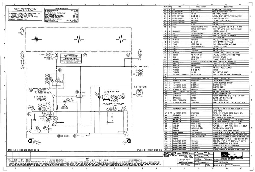
39 1201B Hydraulic Power Supply 2.3. Hydraulic Hookup Connect the Hydraulic Power Supply pressure and return hoses to the Exciter Head pressure and RETURN hoses via the polarized quick disconnects supplied with the system hoses Take care to maintain cleanliness by always attaching caps to the quick disconnects when disconnected When in doubt about hose polarity, the convention is: Supply Pressure - Coupler Supply Return - Nipple Take care that hoses will not rub against sharp objects when pulsating Cable Hookup Connect cable C to the Master Controller rear panel connector and to the servovalve and load cell of the Exciter Head Connect cable B to the rear panel connector of the Master Controller and the displacement connector of the Exciter Head. 3. Theory of Operation The purpose of the Hydraulic Power Supply is to supply clean hydraulic oil at a constant pressure under the varying flow demands of the force exciter head. The system was designed to do this is the most efficient manner, considering power requirements, reliability, safety, ease of maintenance, and operator convenience Circuit Description (Hydraulic) An oil reservoir provides storage for all necessary supply oil and provides some oil cooling. (See Drawing B and B-30288) Mounted on the reservoir are oil level and oil temperature gauges, a temperature sensitive switch, and a reservoir fluid level detector switch for motor shut down. A 3000 psi pressure is achieved by a variable volume, pressure-compensated pump that has a factory set delivery rate. Fluid from the pump first passes through a three-micron (absolute) filter. Should this filter become clogged, a pressure drop builds up across the sensor, causing a switch to trip. This causes the FILTER light to illuminate. The system should not be operated until the filter element is changed. After passing through the filter, oil flows to the pressure output disconnect. HPS - 3
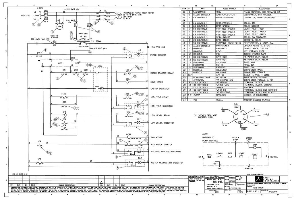
40 1201B Hydraulic Power Supply 3.2. Circuit Description (Electric) The electrical input is wired for either 230, 460; 575V, 60Hz or 380V, 50Hz (See drawing B-30289). The fourth wire (green) is a ground wire and must be tied to earth ground to prevent floating grounds due to an unbalanced load. The pump motor uses the high voltage 3-phase power, while the remaining loads derive 120 volt, single-phase from the step-down Transformer T-1 (designated 14), appropriately connected to the incoming power to provide 120 VAC on the secondary of the transformer. Two-way protection of the three-phase power is provided. A magnetic circuit protector provides over current protection. It is also connected to the electrical box operating handle to disconnect power in the electrical box. Pump motor overload protection is provided by thermal overload heaters in the motor starter, which were specifically designed for the pump motor. A RESET button is conveniently located inside the electrical box, should be thermal overload trip. The pump start relay, 1CR, (designated 5), is a latch-up design so that momentary switches may be used for pump start and pump stop operations. A phase sequence relay 1PM (designated 1) is connected to and monitors the 3-phase incoming line to determine if the phasing is connected correctly to provide proper motor rotation. If the START light is off, any two legs of the incoming lines should be reversed. If the phase is incorrect, 1PM (1) remains de-energized, thus preventing the system from being energized. If the phasing is correct, 1PM (1) energizes, allowing 120 VAC from T-1 (14) to be applied to the pump unit. The T-1 (14) Transformer is fused by 4FU and 5FU. The system POWER switch connects power to the control circuits. If oil temperature is normal, relay 2CR (designated 10) is not energized. Momentarily, pressing the START button will energize 1CR (designated 10) if oil level, temperature, filter, and pressure selection are correct. Relay 1CR (10) energizes the motor starter 1M. Auxiliary contact 1M closes, latching 1CR. A normally closed CR1(5) contact opens, turning off the STOP light. Momentarily pressing the STOP button breaks the latch-up circuit and de-energize 1CR (10) and the pressure relief solenoid. After a short delay, an OFF DELAY contact on 1CR opens, de-energizing the motor-starter coil and causing the pump to stop. HPS - 4
41 1201B Hydraulic Power Supply Relay 3CR (designated 10) is normally not energized unless the oil level drops. If the RED OIL LEVEL LOW light illuminates, the system must be reset by pushing the STOP BUTTON on the Master Controller and oil must be added to the reservoir. When a low oil level is detected, the pump is turned off. Relay 2CR (10) is normally not energized unless the oil temperature exceeds 160 degrees F. If the RED OIL OVERTEMP is illuminated, the system must be reset by pushing the pump STOP BUTTON on the Master Controller after the system cools down. If the differential pressure drop across the filter exceeds approximately 50 psi, the RED FILTER restriction light will illuminate. The Power Supply will NOT shut off, however the filter should be changed when the filter light is illuminated. 4. Description Included on the hydraulic power supply are an oil supply line pressure gauge and a timer which records pump running time. Mounted on the side of the reservoir is an oil level sight gauge with an integral oil temperature thermometer. A reservoir drain is also located on the reservoir. All motor controls and associated electrical equipment are located in the electrical control box. Connections for pressure and return hoses are attached with quick disconnect style connectors Major Components Oil Reservoir Motor Variable volume pressure-compensated Pump Three-micron Filter Assembly Heat Exchanger Motor Control Box Hydraulic Hoses 4.2. Control Components Emergency Stop Switch This switch de-energizes the motor-starter relay, bypassing all shutdown logic; thus causing the motor to stop. Use it only in an emergency situation. WARNING Some operating conditions cause the system to shutdown. HPS - 5
42 1201B Hydraulic Power Supply 4.3. Monitoring Devices Phase Sequence Relay (PHASE Indicator) A phase sequence relay monitors the 3-phase power applied to the unit. If the phasing of the wires is incorrect, the relay will prevent the pump from being energized, and the PHASE CORRECT lamp will not illuminate Filter Pressure Drop Sensor (FILTER Indicator) This sensor sends a signal if the differential pressure across the filter element is excessive. This occurs when the differential pressure drop across the replaceable filter element exceeds 50 psi. Excessive differential pressure occurs when the filter element is clogging, fluid viscosity is too high, fluid temperature is too low, or any combination. At that time, the FILTER light illuminates. Note: There may be times when the system is first started and the oil is cold that the filter light will illuminate. Allow 10 to 20 minutes of operation and if the filter light goes off, then the filter is not dirty and does not need replaced OIL OVERTEMP Indicator The temperature sensor monitors the oil temperature of the reservoir and prevents the pump from running if the oil temperature exceeds 160 degrees F. The OIL OVERTEMP light illuminates, indicating that the maximum allowable oil temperature has been exceeded LOW OIL Indicator The level sensor monitors the oil level in the oil reservoir and prevents the pump from running if the oil level is low. The pump will shut down or fail to start until additional oil is added. The red LOW OIL indicator lamp illuminates during this condition Voltage Applied Indicator A green light indicating power is switched onto the pump motor. The light will ONLY illuminate after depressing the PUMP START button on the Master Controller Hour Meter A service hour meter is included which only runs when the pump motor is running. HPS - 6
43 1201B Hydraulic Power Supply 5. Care and Maintenance Electrocution or severe electrical shock may occur. WARNING When the MAIN power is plugged in, the line side of the motor starter is at line voltage. The Hydraulic Power Supply was designed so that no periodic lubrication on mechanical parts is required. Cleanliness is very important when using sophisticated hydraulic systems, and although a clean room environment is far from necessary, general cleanliness is recommended. Routine maintenance on the overall system should include the following Operating Care Wipe off all cables after each use Never drag cables across the floor Immediately after the hydraulic hoses are disconnected, cover all hydraulic connectors with the covers provided During operation, the oil temperature should never rise above 160 degrees F. (The oil temperature thermal relay shuts down the system at 160 degrees F.) Before each test, check the oil pressure to make sure it is at 3000 psi. A flow screw adjustment is located on the top of the pump compensator assembly. This control is preset at the factory and should not be adjusted (slotted screw with locknut) Before each test, check to make sure that the air heat exchanger blower is operational, that pump maintenance warning lights are not illuminated, and that the phase sequence indicator show proper motor phasing. If for some reason the system has overloaded, the pump motor started thermal overload will trip. Reset it by opening the access door, and pushing the reset button located on the motor starter. HPS - 7
44 1201B Hydraulic Power Supply 5.2. Maintenance To keep the system operating within the specified limits, it is necessary to periodically check the oil level by observing the oil level gauge. Fluid should fill the gauge Oil should be changed after every 1000 hours of pump operation The condition of the filter is displayed by the light on the electrical control box inside the cabinet. The filter requires replacement only when the FILTER light is illuminated. WARNING All oil should be completely drained from the reservoir during transportation. (See drawing B-30287, item 31 for location of reservoir drain hose) 6. Troubleshooting Listed below are some of the common problems which may be experienced with a Power Supply Unit Overheats Overheating may be caused by a clogged heat exchanger, restricted air flow, malfunction of the check valves, or failure of the heat exchanger fan. The efficiency of an oil/ air heat exchanger decreases as the ambient temperature increases. The maximum ambient temperature at which the heat exchange can effectively maintain the oil temperature below 160 degrees F is approximately 100 degrees F. If continuous operation in ambient temperature above 100 degrees F is desired, it is recommended that an oil/ water heat exchanger be added externally to cool the return line oil before it is returned to the oil reservoir Pump de-energizes The pump de-energizing for no apparent reason can be caused by a noisy 3-phase power line where the 3-phase voltage drops below the rated voltage for more than 10 milliseconds. This results in the phase monitor relay 1PM momentarily de-energizing, shutting off the system. HPS - 8
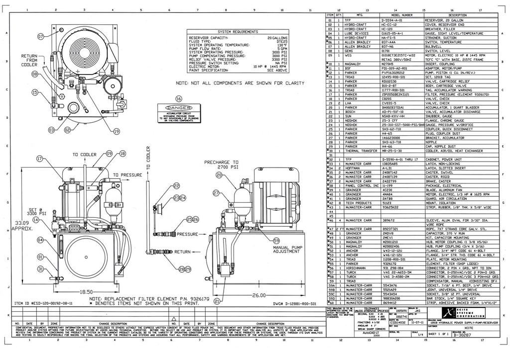
45 1201B Hydraulic Power Supply 7. Specifications Item Specifications Dimensions Height Width Depth Weight Hydraulic Oil Pump Pressure-compensated variable flow axial piston Motor, , 60Hz or , 50Hz lb (without oil) 20 gallons of Mobil DTE psi psi 10 HP Motor Current for 380V, 50 Hz Starting current - 20 Amps Running Current (Full Load) - 18 Amps/phase Inlet Mains Fuses - 50 Amps Reservoir Cooling System Noise Level Replacement Filter Element 20 gallon Air (Maximum ambient room temperature 104 degrees F) 78 3 feet in front of cabinet Parker Filter #932617Q 8. Drawings Model 1201B Outline Dimensions... B Pump/ Reservoir... B Hydraulic Schematic... B Electrical Schematic... B Electrical Box Layout... B HPS - 9
46
47
48
49
50

51 1100, 1200 and 1300 Master Controller
52 Master Controller 1. Introduction The Xcite Master Controller is a compact electronics control package designed to provide all the controls and displays necessary to operate an Xcite exciter system. The latest concepts in electronic design, including plug-in printed circuit boards, flexible systems interface and easy-to-use operator controls, are incorporated in the unit. The Master Controller represents the heart of the closed loop hydraulic exciter system. It enables two variables to be independently controlled simultaneously via the Static Level and Dynamic Level controls. It incorporates automatic gain control in the dynamic loop which allows a constant amplitude of the dynamic variable to be maintained even as the reference frequency of excitation is changed. 2. Theory of Operation The major design concept used in the Xcite Master Controller is one of providing accurate feedback control of an exciter head s capability, such as force, displacement, velocity, acceleration, etc. The Master Controller senses the feedback signals from the appropriate transducers and provides an output drive signal to the exciter head servovalve which will cause the exciter to maintain the desired levels of the static and dynamic variable as determined by the dynamic and static level controls Configurations The master controller can be operated in either a single- or dual-loop configuration Single Loop Single-loop operation is selected by placing the Frequency Range switch to the LOW position. This mode is generally used to control a single variable, usually force or displacement. In this LOW FREQUENCY mode of operation, a dynamic signal is generated by summing the reference frequency present at the PROGRAM INPUT with the Static Level set point signal Dual Loop Dual-loop operation is selected by placing the FREQUENCY RANGE switch to the HIGH position. This mode applies the dynamic feedback signal to the dynamic control loop which incorporates an automatic gain control circuit. This allows a desired dynamic amplitude variable to be set and maintained over a broad frequency range and structure stiffnesses. MC - 1
53 Master Controller 3. Description The Xcite Master Controller (Model 1104, 1204 and 1304) has a variety of inputs and switch selectors which allows the various operational modes of the Exciter Head. Listed below is a description of each connector, switch and indicator located on the Master Controller. MASTER CONTROLLER Front Panel Outside Rear Panel MC - 2
54 Master Controller 3.1. Front Panel (Left and Right Top Section) M-101 M-102 STATIC SIGNAL LEVEL DYNAMIC SIGNAL LEVEL STATIC SETPOINT DYNAMIC SETPOINT R301 R Static Signal Level Meter (M-101) The Static Signal Level is displayed on this meter in Static Force Pounds or Static Displacement Static Set Point (R301) Potentiometer used to set value of desired static variable. The Static Set Point potentiometer is calibrated in percent full scale Dynamic Signal Level Meter (M-102) The Dynamic Signal Level is displayed on this meter in Peak Dynamic Force Pounds Dynamic Set Point (R303) Potentiometer used to set value of desired dynamic variable. The Dynamic Set Point potentiometer is calibrated in Peak Dynamic Force Pounds Excitation Mode (SW304) EXCITATION MODE STATIC STANDBY/RESET STATIC + DYNAMIC SW304 L301 INTERLOCK Used to select operating mode of exciter head. Turn the switch so that the arrow points to the mode of interest. MC - 3
55 Master Controller Standby/ Reset Exciter head is at (or returns to) standby position, aspreset by set-screw potentiometer on rear of Master Controller. The interlock circuits are also reset in this mode. Static Only the static control loop is activated. Static + Dynamic The static and dynamic control loops are activated Interlock (L301) Light indicates when interlock circuits are activated, causing exciter head to return to standby position. Excitation mode control switch must be moved to Reset position to continue operation Dither - ON/ OFF (SW308) DITHER ON STATIC SETPOINT VARIABLE STATIC GAIN OFF FIXED Toggle switch which, when in ON position, provides 400 Hz signal to exciter servovalve. It is used primarily to overcome exciter stiction at low frequencies of operation. (Below 5 Hz) Static Set Point (R301) Indicates desired static level. Calibrated in percent full scale. See Static Gain SW308 R301 Static Gain - Variable/ Fixed (SW305) Toggle switch. In VARIABLE position actuates loop static gain potentiometer (R307). Static Gain (R307) Potentiometer used to set static control loop gain based on the stiffness of the structure under test. Used to eliminate control loop instabilities when using exciter in Static Displacement Mode on a weak structure. MC - 4 SW305 R307 Front Panel (Left) - Bottom Section
56 Master Controller Load Cell LOAD CELL OUTPUT CALIBRATE-ADJ. J301 ZERO OPERATE R302 SW307 R306 Front Panel (Middle) - Bottom Section Output (J301) BNC connector providing load cell output signal for monitoring of the force signal (varies from -10V to +10V depending on the actual value of the force). Duplicated on back of controller. Zero (R302) Set screw potentiometer used to zero the load cell output when there is no load applied Calibrate/ Operate (SW307) Adj. (R306) Set screw potentiometer used to adjust the master controller for the calibration value of the load cell when (SW307) is in the calibrate mode. (See load cell calibration plug for calibration value). Operate Select the operate mode of load cell once calibration is complete Power (SW301) PUMP POWER START STOP DYNAMIC SETPOINT FREQUENCY HIGH LOW SW301 SW302 SW303 R303 SW309 Front Panel (Right) - Bottom Section Push switch for supplying power to master controller. MC - 5
57 Master Controller Pump Start (SW302) Push switch with internal red indicator light to energize power supply. Stop (SW303) Push switch to de-energize hydraulic power supply Dynamic Set Point (R303) Indicates desired peak dynamic level. Calibrated in engineering units. See Frequency Range - HIGH/ LOW (SW309) HIGH - Compressor control of dynamic signal at 5 Hz and above. LOW - Single loop control of force or displacement Rear Panel ER HEAD J305 DISPLACEMENT J311 CALIBRATION RESISTOR J304 STATIC PRELOAD SW310 COMPRESSION/CCW TENSION/CW Rear Panel - Top Section Exciter Head (J305) Input connection for servovalve and load cell cable from exciter head Displacement (J311) Input connection for displacement transducer cable from exciter head Calibration Resistor (J304) Jack input for calibration plug provided with Load Cell Transducer Static Preload (SW310) Dual-position switch establishes sign convention of static preload. When exciter head is operated by pushing on the test article, this switch should be in the COMPRESSION position. If exciter head is operated by pulling on the test structure, this switch should be in the TENSION position. MC - 6
58 Master Controller Interlock (J306) Input connect for interlock function. If external control of this function is not desired, an Xcite supplied mating connector with pins C and D shorted must be used. If user supplied external control is desired, then appropriate contact closure between pins C and D must be supplied. Pins A and B are supplied for interlock of additional external equipment, as required. INTERLOCK J306 PROGRAM INPUT J308 FUSE F301 POWER J307 Rear Panel (Left) - Bottom Section Power (J307) Input connection for cable from hydraulic power supply. When a non-xcite hydraulic power supply is used, this is the input connection for the direct 110V AC power cord Fuse (F301) Use 3 amp fuse for 115 VAC. Use 1.5 amp fuse for 230 VAC Program Input (J308) Input connection for signal from reference oscillator. A 1 volt RMS signal must be provided to ensure system control calibration. MC - 7
59 Master Controller Controlled Variable - Static CONTROLLED VARIABLE STATIC DYNAMIC INPUT INTERNAL (FORCE) INPUT J309 SW311 SW306 EXTERNAL J302 R311 CAL R304 CAL Rear Panel (Middle) - Bottom Section Input (J309) Input BNC connection for externally supplied user-specified static feedback variable. Input signal level should be 5 volts minimum full scale. Also used for Displacement Transducer feedback from the Exciter Head. Internal/ External (SW311) Toggle switch to select as the static controlled variable either the internally available load cell transducer signal or an externally supplied user-specified static feedback signal. Cal. (R311) Set screw potentiometer used to scale externally supplied static feedback variable to 5 volts full scale. Factory set for scaling 10 volts to 5 volts Controlled Variable - Dynamic Input (J302) BNC connection for externally supplied user-specified dynamic feedback variable. Input signal level should be 5 volts peak (minimum) full scale. Internal/ External (SW306) Toggle switch to select as the dynamic controlled variable either the internally available load cell transducer signal or an externally supplied user-specified dynamic feedback signal such as acceleration. Cal. (R304) Set screw potentiometer used to scale down externally supplied dynamic feedback variable to 5 volts peak full scale. MC - 8
XCITE Owner s Manual. Reso-not TM Damping System XCITE 1502C HYDRAULIC POWER SUPPLY
 Reso-not TM Damping System XCITE Owner s Manual 1502C HYDRAULIC POWER SUPPLY Xcite Systems Corporation 675 Cincinnati RDS Batavia - 1 Pike Cincinnati, Ohio 45245 Tel: (239) 980-9093 Fax: (239) 985-0074
HANDE AXLE CO., LTD. (HDCQ)
") Owner s Manual SHAANXI HANDE AXLE CO., LTD. (HDCQ) Xi An, China 1200-3 Laboratory Exciter System 1215-8-T/C Exciter Head S/N 216 5022 Force Load Cell S/N 1042 1302-C-380/50 Hydraulic Power Supply S/N 239
Owner s Manual SHAANXI HANDE AXLE CO., LTD. (HDCQ) Xi An, China 1200-3 Laboratory Exciter System 1215-8-T/C Exciter Head S/N 216 5022 Force Load Cell S/N 1042 1302-C-380/50 Hydraulic Power Supply S/N 239
XCITE Owner s Manual. Reso-not TM Damping System XCITE. 1300T-1 System 1300T-2 System 1300T-3 System
 Reso-not TM Damping System XCITE Owner s Manual 1300T-1 System 1300T-2 System 1300T-3 System Xcite Systems Corporation 675 Cincinnati RDS Batavia - 1 Pike Cincinnati, Ohio 45245 Tel: (239) 980-9093 Fax:
XCITE. Reso-not TM Damping System XCITE. Model No ZSP-101-P2-38 Foot Mount Damper with 1 Quart Accumulator System
 XCITE Model No. 1206-ZSP-101-P2-38 Foot Mount Damper with 1 Quart Accumulator System Xcite Systems Corporation 675 Cincinnati RDS Batavia - 1 Pike Cincinnati, Ohio 45245 Tel: (239) 980-9093 Fax: (239)
MODEL 422 Submersible Pump Controller
 MODEL 422 Submersible Pump Controller Monitors True Motor Power (volts x current x power factor) Detects Motor Overload or Underload Operates on 120 or 240VAC, Single-phase or 3-phase Built-in Trip and
TRANSDUCER INSTRUCTION MANUAL... TYPE SLIM CELL TRANSDUCER. INSTRUCTION NUMBER: AO of 9
 CLEVELAND-KIDDER SLIM CELL TRANSDUCER INSTRUCTION MANUAL... TYPE SLIM CELL TRANSDUCER INSTRUCTION NUMBER: AO-70165 1 of 9 1.0 GENERAL INFORMATION 1.1 RECEIVING AND UNPACKING Handle and unpack the equipment
Troubleshooting Bosch Proportional Valves
 Troubleshooting Bosch Proportional Valves An Informative Webinar Developed by GPM Hydraulic Consulting, Inc. Instructed By Copyright, 2009 GPM Hydraulic Consulting, Inc. TABLE OF CONTENTS Bosch Valves
SHOCK ABSORBER/DAMPER TESTING MACHINE
 SHOCK ABSORBER/DAMPER TESTING MACHINE Dampening force of a shock absorber is directly proportional to velocity and this parameter needs to be precisely controlled. A small variation of 1mm in a stroke
MD10. Engine Controller. Installation and User Manual for the MD10 Engine Controller. Full Version
 MD10 Engine Controller Installation and User Manual for the MD10 Engine Controller. Full Version File: MartinMD10rev1.4.doc May 16, 2002 2 READ MANUAL BEFORE INSTALLING UNIT Receipt of shipment and warranty
Installation & Operation Manual. Electrak 10 Series / Electromechanical Linear Actuator
 www..com Installation & Operation Manual Electrak 10 Series / Electromechanical Linear Actuator INTRODUCTION Thomson has many years of experience designing and manufacturing linear actuators for a wide
Models & Options Lubrication. 1/2 Through 10 Hp Models 1Ø 3Ø 1/2 Through 10 Hp Models 1Ø and 3Ø
 P U R E A I R T E C H N O L O G Y Climate Control Duplex Please read and save these instructions. Read carefully before attempting to assemble, install, operate or maintain the product described. Protect
Tekleen GB6 & GB7 USERS AUTOMATIC FILTERS, INC. MANUAL
 AUTOMATIC FILTERS, INC. 67 S. LA CIENEGA BLVD. LOS ANGELES, CA 90034 30 839 88 800 336 94 FAX 30 839 6878 www.tekleen.com info@tekleen.com Tekleen GB6 & GB7 USERS MANUAL GB6 & GB7 USERS MANUAL AUTOMATIC
5001TCP SPEED CONTROLLER
 INSTALLATION AND SETTING UP MANUAL 5001TCP SPEED CONTROLLER WARNING Disconnect all incoming power before working on this equipment. Follow power lockout procedures. Use extreme caution around electrical
DYNAMOMETER CONTROLLER MODEL 5220 INSTRUCTION AND REFERENCE MANUAL
 DYNAMOMETER CONTROLLER MODEL 5220 INSTRUCTION AND REFERENCE MANUAL IDENTIFICATION DIAGRAMS MODEL 5220 FRONT PANEL MODEL 5220 REAR PANEL CONTENTS 1.0 Introduction 2.0 Connecting Instructions 3.0 Operational
Pressure Makeup Jockey Pump Controller
 Hubbell Industrial Controls, Inc. A subsidiary of Hubbell Incorporated 4301 Cheyenne Dr. Archdale, NC 27263 Telephone (336) 434-2800 FAX (336) 434-2803 Instruction Manual Pressure Makeup Jockey Pump Controller
Servo and Proportional Valves
 Servo and Proportional Valves Servo and proportional valves are used to precisely control the position or speed of an actuator. The valves are different internally but perform the same function. A servo
5001TCP SPEED CONTROLLER
 VARIABLE SPEED DRIVE CONTROLLER INSTALLATION AND SETTING UP MANUAL 5001TCP SPEED CONTROLLER With PC101 Torque Limit Control WARNING Disconnect all incoming power before working on this equipment. Follow
Model LA 4400 Time Delay OFF Controller
 ISIMET LA Series Model LA 4400 Time Delay OFF Controller Installation, Operation and Maintenance Manual Application: The Time Delay OFF Controller with integral 24-hr. programmable time clock operates
APS 420 ELECTRO-SEIS Long Stroke Shaker with Linear Ball Bearings Page 1 of 5
 Long Stroke Shaker with Linear Ball Bearings Page 1 of 5 The APS 420 ELECTRO-SEIS shaker is a long stroke, electrodynamic force generator specifically designed to be used alone or in arrays for studying
SECTION DC POWER SUPPLY/BATTERY CHARGER
 SECTION 26 33 05 PART 1 - GENERAL 1.1 THE REQUIREMENT A. The CONTRACTOR shall provide the single-phase heavy-duty industrial battery charger and all accessories required, complete and operable, in accordance
SHORT-STOP. Electronic Motor Brake Type G. Instructions and Setup Manual
 Electronic Motor Brake Type G Instructions and Setup Manual Table of Contents Table of Contents Electronic Motor Brake Type G... 1 1. INTRODUCTION... 2 2. DESCRIPTION AND APPLICATIONS... 2 3. SAFETY NOTES...
MPT-250B SPECIFICATIONS AND OPERATING INSTRUCTIONS
 1. SAFETY The MPT-250B Wire Crimp Pull Tester is a force measurement device, and as such should be operated with due caution. Operators should wear safety glasses for eye protection because the crimp under
MaxPak Plus Analog DC V S Drive
 Three-Phase 3-600 HP non-regenerative and 5-150 HP regenerative drives Designed to accommodate a wide range of industrial requirements, the DC V S Drive has been widely applied worldwide. Selected ratings
Model LA 4100 Time Delay OFF Controller
 ISIMET LA Series Model LA 4100 Time Delay OFF Controller Installation, Operation and Maintenance Manual Application: The Time Delay OFF Controller operates as a single output controller where the application
Advantage-D. Operating Instructions and Maintenance Manual. Central Vacuum Systems (Expandable/Modular Models) (Ver.
 (Ver.") Advantage-D Series 3 Central Vacuum Systems (Expandable/Modular Models) (Ver. 8/05) Operating Instructions and Maintenance Manual DESCRIPTION The Becker Advantage-D and Advantage-L central vacuum systems
Advantage-D Series 3 Central Vacuum Systems (Expandable/Modular Models) (Ver. 8/05) Operating Instructions and Maintenance Manual DESCRIPTION The Becker Advantage-D and Advantage-L central vacuum systems
APS 113 ELECTRO-SEIS Long Stroke Shaker with Linear Ball Bearings Page 1 of 5
 Long Stroke Shaker with Linear Ball Bearings Page 1 of 5 The ELECTRO-SEIS shaker is a long stroke, electrodynamic force generator specifically designed to be used alone or in arrays for studying dynamic
ADI-125/750 ADI-125/1500 ADI-125/2500
 Manufacturer of Dimensions TM Inverters 4467 White Bear Parkway St. Paul, MN 55110 Phone: 651-653-7000 Fax: 651-653-7600 E-mail: inverterinfo@sensata.com Web: www.dimensions.sensata.com 121094B OWNERS
model ps600 Address all communications and shipments to: FEDERAL SIGNAL CORPORATION
 MODEL: PS600 HZ: 60 A model ps600 installation and service manual for federal model ps600 FEDERAL SIGNAL CORPORATION POWER SUPPLY VOLTS: SERIES: 120VAC FEDERAL SIGNAL CORPORATION UNIVERSITY PARK, IL. U.S.A.
Positive Displacement Pump
 www.conairgroup.com U S E R G U I D E UGC028-1105 Positive Displacement Pump Models PD 3. 5, 7.5, 10, 15 and 25 Corporate Office: 724.584.5500 l Instant Access 24/7 (Parts and Service): 800.458.1960 l
MODEL 520 REMOTE START ENGINE MANAGEMENT SYSTEM
 MODEL 520 REMOTE START ENGINE MANAGEMENT SYSTEM DSE 520 ISSUE 4 4/4/02 MR 1 TABLE OF CONTENTS Section Page INTRODUCTION... 4 CLARIFICATION OF NOTATION USED WITHIN THIS PUBLICATION.... 4 1. OPERATION...
24/3000H-3PH 24/4500H-3PH 24/6000H-3PH
 Manufacturer of Dimensions TM Inverters 4467 White Bear Parkway St. Paul, MN 55110 Phone: 651-653-7000 Fax: 651-653-7600 E-mail: inverterinfo@sensata.com Web: www.dimensions.sensata.com 120015D OWNERS
DENISON HYDRAULICS Jupiter 500 Driver Card Series S
 Back to Content DENISON HYDRAULICS Jupiter 500 Driver Card Series S20-11712-0 Publ. 9-AM681 E-Mail: denison@denisonhydraulics.com Internet: http://www.denisonhydraulics.com SYSTEM FEATURES SYSTEM FEATURES
TOWER MAXI T SINGLE CONVERSION ON LINE UPS SYSTEMS
 INSTRUCTION MANUAL TOWER MAXI T SINGLE CONVERSION ON LINE UPS SYSTEMS September 2000 TOWER UPS DISTRIBUTION (PTY) LTD 1 1. INTRODUCTION T A B L E O F C O N T E N T S 1.1 General Description... 3 1.2 Features...
INSTRUCTION MANUAL FOR. VOLTAGE REGULATOR Model: APR Part Number:
 INSTRUCTION MANUAL FOR VOLTAGE REGULATOR Model: APR 125-5 Part Number: 9 1688 00 100 Publication Number: 9 1688 00 990 Revision H: 07/2001 CONTENTS SECTION 1 GENERAL INFORMATION...1-1 DESCRIPTION... 1-1
Product Guide: Series III Pump Control Board Set (RoHS)
") revised 04/08/10 Description: The Series III Pump Control Board Set provides motor drive and pump control for a wide assortment of pumps from Scientific Systems, Inc. The assembly consists of two circuit
revised 04/08/10 Description: The Series III Pump Control Board Set provides motor drive and pump control for a wide assortment of pumps from Scientific Systems, Inc. The assembly consists of two circuit
TECHNICAL PAPER 1002 FT. WORTH, TEXAS REPORT X ORDER
 I. REFERENCE: 1 30 [1] Snow Engineering Co. Drawing 80504 Sheet 21, Hydraulic Schematic [2] Snow Engineering Co. Drawing 60445, Sheet 21 Control Logic Flow Chart [3] Snow Engineering Co. Drawing 80577,
Displacement Sensor. Model 8739, 8740, 8741
 w Technical Product Information Displacement Sensor 1. Introduction... 2 2. Preparations for use... 2 2.1 Unpacking... 2 2.2 Grounding and potential connection... 2 2.3 Storage... 2 3. Principle of operation...
IMI vibration switch USER MANUAL INSTALLATION - OPERATION - MAINTENANCE
 USER MANUAL IMI vibration switch INSTALLATION - OPERATION - MAINTENANCE Z0929039_A ISSUED 03/2017 READ AND UNDERSTAND THIS MANUAL PRIOR TO OPERATING OR SERVICING THIS PRODUCT. contents Overview General
M T E C o r p o r a t i o n MATRIX FILTER. SERIES B Volts, 50HZ USER MANUAL PART NO. INSTR REL MTE Corporation
 M T E C o r p o r a t i o n MATRIX FILTER SERIES B 380-415 Volts, 50HZ USER MANUAL PART NO. INSTR - 015 REL. 060628 2006 MTE Corporation IMPORTANT USER INFORMATION NOTICE The MTE Corporation Matrix Filter
R & D SPECIALTIES ROTROL I USER'S MANUAL
 R & D SPECIALTIES ROTROL I USER'S MANUAL TABLE OF CONTENTS INTRODUCTION...2 SPECIFICATIONS...2 CONTROLS AND INDICATORS...3 TIME DELAYS...4 INSTALLATION...5 SYSTEM OPERATION...9 TROUBLESHOOTING...13 OPTIONAL
OWNERS MANUAL JANUARY 2007 ISO
 Manufacturer of Dimensions TM Inverters 4467 White Bear Parkway St. Paul, MN 55110 Phone: 651-653-7000 Fax: 651-653-7600 E-mail: inverterinfo@sensata.com Web: www.dimensions.sensata.com 121231B OWNERS
Reproduction or other use of this Manual, without the express written consent of Vulcan, is prohibited.
 SERVICE MANUAL ELECTRIC BRAISING PANS (30 & 40 GALLON) VE30 VE40 ML-126849 ML-126850 VE40 SHOWN - NOTICE - This Manual is prepared for the use of trained Vulcan Service Technicians and should not be used
BLDPN30001 Series. 30A Brushless DC Controller. User s Guide E. Landon Drive Anaheim, CA
 BLDPN30001 Series 30A Brushless DC Controller User s Guide A N A H E I M A U T O M A T I O N 4985 E. Landon Drive Anaheim, CA 92807 e-mail: info@anaheimautomation.com (714) 992-6990 fax: (714) 992-0471
Airpax Dimensions, Inc.
 Airpax Dimensions, Inc. 4467 White Bear Parkway (651) 653-7000 St. Paul, MN 55110-7626 Fax (651) 653-7600 121177B OWNERS MANUAL JANUARY 2007 Airpax Dimensions, Inc. Uninterruptible Power System OWNERS
Power InverterTM Watt. Continuous. User's Manual. WAGAN Corp. Limited Warranty Registration Form. Item no
 WAGAN Corp. Limited Warranty Registration Form All WAGAN Corporation products are warranted to the original purchaser of this product. Warranty Duration: This product is warranted to the original purchaser
Model LA 4300 Time Delay OFF Controller
 ISIMET LA Series Model LA 4300 Time Delay OFF Controller Installation, Operation and Maintenance Manual Application: The Time Delay OFF Controller operates as a single output controller where the application
Patient Care Facility
 ISIMET Patient Care Facility DLA Controller Individual Room Configuration Style 1 W/ Ver 4.41 pcb & Pulse Relay pcb Installation, Operations, Start-up and Maintenance Instructions Meets all Standards for
Drug Testing Labs. Style 2 W/ Ver 4.41 pcb & Pulse Relay pcb(s) Installation, Operations, Start-up and Maintenance Instructions
 Installation, Operations, Start-up and Maintenance Instructions") ISIMET Drug Testing Labs DLA Controller Style 2 W/ Ver 4.41 pcb & Pulse Relay pcb(s) Installation, Operations, Start-up and Maintenance Instructions Meets all Standards for Canadian Industrial Control
ISIMET Drug Testing Labs DLA Controller Style 2 W/ Ver 4.41 pcb & Pulse Relay pcb(s) Installation, Operations, Start-up and Maintenance Instructions Meets all Standards for Canadian Industrial Control
D660 Series Servo-Proportional Control Valves with Integrated Electronics ISO 4401 Size 05 to 10
 D660 Series Servo-Proportional Control Valves with Integrated Electronics ISO 4401 Size 05 to 10 OVERVIEW Section Page MOOG SERVO-PROPORTIONAL CONTROL VALVES Overview 2 3 Technical Data 4 5 Electronics
M T E C o r p o r a t i o n MATRIX FILTER. SERIES B Volts, 50HZ USER MANUAL PART NO. INSTR REL MTE Corporation
 M T E C o r p o r a t i o n MATRIX FILTER SERIES B 380-415 Volts, 50HZ USER MANUAL PART NO. INSTR - 015 REL. 040709 2003 MTE Corporation IMPORTANT USER INFORMATION NOTICE The MTE Corporation Matrix Filter
Patient Care Facility
 ISIMET Patient Care Facility DLA Controller Individual Room Configuration Style 1 W/ Ver 4.41 pcb & Pulse Relay pcb Installation, Operations, Start-up and Maintenance Instructions Meets all Standards for
HT Dielectric Withstand Tester Volts AC Output 25mA Leakage Option
 HT-10000 Dielectric Withstand Tester 0-10000 Volts AC Output 25mA Leakage Option Instruction Manual COMPLIANCE WESTUSA Dear Customer: Congratulations! Compliance West USA is proud to present you with your
ValveMate 7000 Controller Operating Manual
 A NORDSON COMPANY ValveMate 7000 Controller Operating Manual Steady Test Clear Time Set Fast Slow POWER RUN SETUP CYCLE A NORDSON COMPANY VALVEMATE 7000 Run Setup Purge Program Fast Slow Time Set Pressure
Operation & Service Manual
 Operation & Service Manual Model: 5B20 Hydraulic Power Unit 07/2011 - Rev. 06 Includes Illustrated Parts Lists 1740 Eber Rd Tronair, Inc. Phone: (419) 866-6301 Holland, OH 43528-9794 www.tronair.com 800-426-6301
Drug Testing Labs. Style 2 W/ Ver 4.41 pcb & Pulse Relay pcb(s) Installation, Operations, Start-up and Maintenance Instructions
 Installation, Operations, Start-up and Maintenance Instructions") ISIMET Drug Testing Labs DLA Controller Style 2 W/ Ver 4.41 pcb & Pulse Relay pcb(s) Installation, Operations, Start-up and Maintenance Instructions Meets all Standards for Canadian Industrial Control
ISIMET Drug Testing Labs DLA Controller Style 2 W/ Ver 4.41 pcb & Pulse Relay pcb(s) Installation, Operations, Start-up and Maintenance Instructions Meets all Standards for Canadian Industrial Control
AIR CLEANERS Model MC 3000 OWNER S MANUAL CAUTION Read complete instructions before operating. Please file for future reference.
 AIR CLEANERS Model MC 3000 OWNER S MANUAL CAUTION Read complete instructions before operating. Please file for future reference. MODEL MC 3000 SPECIFICATION Input Volts: 208-230/430 VAC, 60Hz, 3 Phase
Pro-Series/ Electromechanical Linear Actuator
 Pro-Series/ Electromechanical Linear Actuator Installation and Operation Manual P-264-PROSERIES (08/10) Keep all product manuals as a product component during the life span of the product. Pass all product
ENGINE GOVERNING SYSTEMS LSM672 LOAD SHARING MODULE. GOVERNORS AMERICA CORP. 720 Silver Street Agawam, MA , USA MEMBER
 ENGINE GOVERNING SYSTEMS LSM672 LOAD SHARING MODULE MEMBER GOVERNORS AMERICA CORP. 720 Silver Street Agawam, MA 01001-2907, USA LSM672 LOAD SHARING MODULE PRODUCT TECHNICAL INFORMATION PTI 4000 AUGUST
three different ways, so it is important to be aware of how flow is to be specified
 Flow-control valves Flow-control valves include simple s to sophisticated closed-loop electrohydraulic valves that automatically adjust to variations in pressure and temperature. The purpose of flow control
ENGINE GOVERNING SYSTEMS
 ENGINE GOVERNING SYSTEMS ESD5400 Series Speed Control Unit INSTALLATION The speed control unit is rugged enough to be placed in a control cabinet or engine mounted enclosure with other dedicated control
ECLIPSE Laundry Dispenser Controller
 ECLIPSE Laundry Dispenser Controller Reference Manual Programming and Operation Online and downloadable Product Manuals and Quick Start Guides are available at www.hydrosystemsco.com Please check online
Updated: October 2012
 T: (630) 794-5100 EMERGENCY POWER FUEL SYSTEMS Earthsafe Systems, Inc. 7320 S. Madison Willowbrook, IL 60527 F: (630) 794-5106 info@earthsafe.com www.earthsafe.com Updated: October 2012 The information
University of Houston Master Construction Specifications Insert Project Name SECTION ELECTRONIC VARIABLE SPEED DRIVES PART 1 - GENERAL
 SECTION 23 04 10 ELECTRONIC VARIABLE SPEED DRIVES PART 1 - GENERAL 1.1 RELATED DOCUMENTS: A. The Conditions of the Contract and applicable requirements of Division 1, "General Requirements", and Section
Model 930 Power Control System Instruction Manual
 Model 930 Power Control System Instruction Manual Publication No. A105328-001 Rev A December 2000 Another quality product from: 7128 Shady Oak Rd, Eden Prairie MN 55344 Phone: (952) 949-9009 Fax: (952)
MPT-200A SPECIFICATIONS AND OPERATING INSTRUCTIONS
 MPT-200A SPECIFICATIONS AND OPERATING INSTRUCTIONS DATASHEET 1. SAFETY The MPT-200A Wire Crimp Pull Tester is a force measurement device, and as such should be operated with due caution. Operator should
Model 616 Rotating Disk Electrode Instruction Manual
 Model 616 Rotating Disk Electrode Instruction Manual 219303 C / 1202 Printed in USA Advanced Measurement Technology, Inc. a/k/a Princeton Applied Research, a subsidiary of AMETEK, Inc. WARRANTY Princeton
Dimensions 12/800N 12/1200N D. DC to AC Power Inverters. OWNERS MANUAL for Models: OWNERS MANUAL April ISO 9001:2000 Certified Company
 Manufacturer of Dimensions Inverters 4467 White Bear Parkway St. Paul, MN 55110 Phone: 651-653-7000 Fax: 651-653-7600 E-mail: inverterinfo@sensata.com Web: www.dimensions.sensata.com OWNERS MANUAL April
APS 400 ELECTRO-SEIS. Long Stroke Shaker Page 1 of 5. Applications. Features
 Long Stroke Shaker Page 1 of 5 The APS 400 ELECTRO-SEIS is a force generator specifically designed to be used alone or in arrays for studying dynamic response characteristics of various structures. It
Washer Extractor. Balancing Systems
 Washer Extractor Balancing Systems Why is it Necessary Out of Balance conditions can cause a tremendous level of force. 1 G machine that is out of balance 1 lb is 1lbf 300 G machine that is 40 lbs out
MIL-24/2600Q MIL-24/3200DQ
 Manufacturer of Dimensions TM Inverters 4467 White Bear Parkway St. Paul, MN 55110 Phone: 651-653-7000 Fax: 651-653-7600 E-mail: inverterinfo@sensata.com Web: www.dimensions.sensata.com 121473B OWNER'S
POWER SUPPLY MODEL XP-800. TWO AC VARIABLE VOLTAGES; 0-120V and 7A, PLUS UP TO 10A. Instruction Manual. Elenco Electronics, Inc.
 POWER SUPPLY MODEL XP-800 TWO AC VARIABLE VOLTAGES; 0-120V and 0-40V @ 7A, PLUS 0-28VDC @ UP TO 10A Instruction Manual Elenco Electronics, Inc. Copyright 1991 Elenco Electronics, Inc. Revised 2002 REV-I
BLHV, BLHV-1. High Voltage Step Motor Driver. User s Guide. (714) fax: (714) website:
 fax: (714) website:") BLHV, BLHV-1 High Voltage Step Motor Driver User s Guide A N A H E I M A U T O M A T I O N 910 East Orangefair Lane, Anaheim, CA 92801 e-mail: info@anaheimautomation.com #L010015 (714) 992-6990 fax: (714)
BLHV, BLHV-1 High Voltage Step Motor Driver User s Guide A N A H E I M A U T O M A T I O N 910 East Orangefair Lane, Anaheim, CA 92801 e-mail: info@anaheimautomation.com #L010015 (714) 992-6990 fax: (714)
Induction Power Supplies
 Induction Power Supplies 7.5kW; 135 400kHz 480V version (Integral Heat Station) User s Guide Model 7.5-135/400-3-480 SMD Control Brds Rev. D 5/08 Table of Contents 1. Specifications and features...3 2.
Cleveland-Kidder Ultra
 LOW PROFILE Low Profile Load Cell Providing up to a 40:1 Tension Range Performance Benefits Cleveland Motion Controls new Ultra Line Slim Cell is part of the new Line Tension family. a unique low-profile
A6Z OPERATING MANUAL
 A6Z OPERATING MANUAL TABLE OF CONTENTS Introduction... p. 2 Features... p. 2 Description... p. 3 Theory of Operation... p. 3 Installation... p. 4 Electrical Connections... p. 5 Options... p. 6 Warranty.p.
RoughDeck TM FXB Flexure Base Floor Scale. Installation/Operation Manual
 RoughDeck TM FXB Flexure Base Floor Scale Installation/Operation Manual SM 32958 13 Contents 1. Introduction... 1 1.1 Scale Components... 1 1.2 Operating Requirements... 2 1.3 How Flexure Levers Work...
DC Variable Speed Drive Panel
 DC Variable Speed Drive Panel Installation, Operation & Maintenance Instruction Manual Bulletin #: CC-IOM-0103-D Manufacturers of Quality Pumps, Controls and Systems ENGINEERED PUMP OPERATIONS 2883 Brighton
DC to AC Power Inverters
 Manufacturer of Dimensions TM Inverters 4467 White Bear Parkway St. Paul, MN 55110 Phone: 651-653-7000 Fax: 651-653-7600 E-mail: inverterinfo@sensata.com Web: www.dimensions.sensata.com ISO 9001:2000 Certified
AUTO REEL -AS MODEL #: AS AUTOMATIC CORD REEL WITH AUTO SAFE INSTRUCTION MANUAL
 INSTRUCTION MANUAL AUTO REEL -AS AUTOMATIC CORD REEL WITH AUTO SAFE MODEL #: 091-220-20-120-AS INPUT: 120 Volts, 50/60 Hz, 20 Amps File: IM_091-220-20-120-AS_revA.indd Rev: A Revised By: JM Date: 06-09-2015
DC to AC Power Inverters
 Manufacturer of Dimensions TM Inverters 4467 White Bear Parkway St. Paul, MN 55110 Phone: 651-653-7000 Fax: 651-653-7600 E-mail: inverterinfo@sensata.com Web: www.dimensions.sensata.com 121114C OWNERS
UniTorq UTQ Quarter-Turn Actuator Installation and Operation Manual
 UniTorq UTQ 1.5 6.4 Quarter-Turn Actuator Installation and Operation Manual Thank you for purchasing our UTQ 1.5-6.0 Electric Actuators Before installation or operation of the actuator carefully review
1200+ WITH LVD (LOW VOLTAGE DISCONNECT) USER GUIDE
 USER GUIDE") 1200+ WITH LVD (LOW VOLTAGE DISCONNECT) USER GUIDE INST045 Doc 2.00 CONTENTS General Information...2 Operating Environment...6 Features...7 Installation Instructions...8 Inverter Ground and Remote Sense
1200+ WITH LVD (LOW VOLTAGE DISCONNECT) USER GUIDE INST045 Doc 2.00 CONTENTS General Information...2 Operating Environment...6 Features...7 Installation Instructions...8 Inverter Ground and Remote Sense
MDC V, 30A Brushless Controller. User s Guide L East Orangefair Lane, Anaheim, CA
 MDC150-012301 12V, 30A Brushless Controller User s Guide A N A H E I M A U T O M A T I O N 910 East Orangefair Lane, Anaheim, CA 92801 e-mail: info@anaheimautomation.com (714) 992-6990 fax: (714) 992-0471
MCV106A. Hydraulic Displacment Control-PV DESCRIPTION FEATURES ORDERING INFORMATION. BLN Issued: March 1991
 DESCRIPTION MCV106A Hydraulic Displacment Control-PV Issued: March 1991 The MCV106A Hydraulic Displacement Control (HDC) is a costeffective hydraulic pump stroke control which uses mechanical feedback
12 Series Linear Actuators. Operation & Maintenance Manual, Analog Positioner Installation
 12 Series Linear Actuators Operation & Maintenance Manual, Analog Positioner Installation 6810 POWERLINE DR.-FLORENCE, KY. 41042 - TELEPHONE 859-727-7890, TOLL FREE 1-800-662-9424 FAX. 859-727-4070, E-MAIL:
Eaton Electronic Proportional (EP) Control for Medium Duty Piston Pumps
 Control for Medium Duty Piston Pumps") Eaton Electronic Proportional (EP) Control for Medium Duty 72400 Piston Pumps Table of Contents Introduction....................................................... 3 Identification of Components.........................................
Eaton Electronic Proportional (EP) Control for Medium Duty 72400 Piston Pumps Table of Contents Introduction....................................................... 3 Identification of Components.........................................
MAINFRAME HOT RUNNER TEMPERATURE CONTROL SYSTEMS. Instruction Manual
 MAINFRAME HOT RUNNER TEMPERATURE CONTROL SYSTEMS Instruction Manual Copyright, Athena Controls, Inc., 2006 Printed in USA CompuStep is a registered trademark of Athena Controls, Inc. SafeChange is a trademark
dv Sentry TM 208V 600V INSTALLATION GUIDE Quick Reference ❶ How to Install Pages 6 14 ❷ Startup/Troubleshooting Pages WARNING
 dv Sentry TM 208V 600V INSTALLATION GUIDE FORM: DVS-IG-E REL. January 2018 REV. 003 2018 MTE Corporation High Voltage! Only a qualified electrician can carry out the electrical installation of this filter.
PRODUCT INFORMATION BULLETIN
 724-283-4681 724-283-5939 (fax) PRODUCT INFORMATION BULLETIN DESCRIPTION The, Model 10-7100 is one in a series of critical speed switches that monitor speed and detect motion in all types of machinery
BRAVO Inverter/Battery Charger. Table of Contents
 BRAVO 1050 Inverter/Battery Charger Table of Contents Introduction... 2 General Description... 2 Specifications... 3 Installation: Hardwire Units... 4 Operation: Hardwire Units... 5-6 Installation: GFCI
Operator's Manual. Storage System. Ultrasound Probe Cabinet. Manufactured by:
 Storage System Ultrasound Probe Cabinet Operator's Manual Manufactured by: CIVCO Medical Solutions 102 First Street South Kalona, IA 52247 USA 319.248.6757 / 800.445.6741 WWW.CIVCO.COM Copyright 2018 All
Model 550 Series Vibration Switches
 OPERATION MANUAL Vibration Switches Includes: 550 550M 550-X 550M-X Page 2 SECTION TITLE PAGE 1. INTRODUCTION... 2 2. FEATURES... 3 3. WIRING... 4 4. ANALOG METER... 4 5. TESTING... 4 6. INSTALLATION...
********SERVICE MANUAL********* MODELS:
 ********SERVICE MANUAL********* MODELS: -------------- 7553-70 Variable Speed Drive/Controller System, 600 rpm, 115v 7553-71 Variable Speed Controller only, 600 rpm,115v 7553-80 Variable Speed Drive/Controller
Valcom Failsafe Unit. 1620ESv2 SERIES. Operation and Maintenance Manual
 Valcom Failsafe Unit 1620ESv2 SERIES Operation and Maintenance Manual Table of Contents Section Title Page 1. - Introduction.. 2. - Unpacking the Failsafe unit. 3. - Installation 3.1 - Auto / Timed UPS
Data Bulletin. Ground-Censor Ground-Fault Protection System Type GC Class 931
 Data Bulletin 0931DB0101 July 2001 Cedar Rapids, IA, USA Ground-Censor Ground-Fault Protection System Type GC Class 931 09313063 GT Sensor Shunt Trip of Circuit Interrupter Window Area for Conductors GC
Installation and Maintenance Instructions. World Leader in Modular Torque Limiters. PTM-4 Load Monitor
 World Leader in Modular Torque Limiters Installation and Maintenance Instructions PTM-4 Load Monitor 1304 Twin Oaks Street Wichita Falls, Texas 76302 (940) 723-7800 Fax: (940) 723-7888 E-mail: sales@brunelcorp.com
TIN KNOCKER TK H1652 Hydraulic Shear
 TIN KNOCKER TK H1652 Hydraulic Shear INSTRUCTIONS & PARTS DIAGRAM TAAG INDUSTRIES CORP. 1550 SIMPSON WAY, ESCONDIDO, CA 92029 Tel: (800) 640-0746 Fax: (760) 727-9948 Website: www.tinknocker.com Email:
TL-105-D COLUMN HEATER
 TL-105-D COLUMN HEATER INSTRUCTION MANUAL Timberline Instruments Inc. 1880 S. Flatiron Ct., Unit I Boulder, Colorado 80301 Ph: (303) 440-8779 Fx: (303) 440-8786 info@timberlineinstruments.com www.timberlineinstruments.com
Pump Installation and Service Manual HRS Hydromatic Retractable System
 Pump Installation and Service Manual HRS Hydromatic Retractable System NOTE! To the installer: Please make sure you provide this manual to the owner of the pumping equipment or to the responsible party
CBC-802 Plug-In Clutch/Brake Control with Solid State Switching
 DIST. AUTORIZADO Plug-In Clutch/Brake Control with Solid State Switching P-29-5 19-0409 Service & Installation Instructions An Altra Industrial Motion Company DIST. AUTORIZADO Brake (Red) and clutch (Green)