Ford CFT 30 Introduction. Presented by: Bill Brayton ATRA Senior Research Technician
|
|
|
- Leslie O’Neal’
- 5 years ago
- Views:
Transcription


1 Ford CFT 30 Introduction Presented by: Bill Brayton ATRA Senior Research Technician
2 Connections Handout Questions Survey
3 Welcome To Today s Presentation Sponsored By:
4


5 Thank you to our Co- Sponsors
6 Any Questions Or Comments Please Contact Lance Wiggins At ATRA
7 Webinar Schedule ATRA Webinar Schedule Description Jan 27/28 CFT 30 Rebuild Feb 10/11 Lineartronic CVT Introduction Feb 24/25 ZF8HP Introduction March 10/11 DPS6 Introduction March 24/25 Honda 6 Rebuild April 7/8 8L90 Introduction April 21/22 CFT30 Rebuild May 5/6 948TE Introduction May 19/20 Lineartronic CVT Rebuild June 2/3 ZF8HP Rebuild June 23/24 6R140 Introduction July 7/8 DPS6 Internal Operation July 21/22 U660 Introduction and Rebuild Aug 4/5 8L90 Internal Aug 18/19 01J Problems & Fixes Sept 1/2 948TE Internal Sept 15/16 5R110W Problems & Fixes Sept 29/30 Lineartronic CVT Problems & Fixes Oct 13/14 6R140 Problems & Fixes
8


9 CFT 30 Applications Five Hundred Freestyle Mariner Hybrid


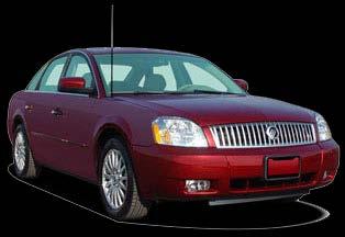

10 CFT 30 Applications Milan Hybrid Montego

11 Uses Motorcraft CVT designed fluid No discreet gear shifts and no interruptions in power flow during accelerations Infinite number of gear ratios so the optimum engine operating point can be found Uses a drive chain not a belt A single planetary is used to change the rotation of the pulley assembly for forward and reverse driving ranges The TCM is internally mounted to the valve body (Mechatronic)
12 Transaxle Electronic Control System The following is a list of components that are incorporated within the mechatronic assembly: Transmission Control Module (TCM) Transmission Fluid Temperature (TFT) Sensor Speed Sensors Turbine Shaft Sensor (TSS) and Primary Variator Speed Sensor Valve body Pressure Control Solenoids Pressure Sensors The output shaft speed (OSS) is part of the transaxle electronic control system but it is not part of the mechatronic assembly. The OSS sensor is bolted to the case and reads the differential gear.
13 Depowering the Hybrid WARNING: When servicing the high-voltage system, establish a buffer zone per the specified procedure. Failure to follow this instruction may result in serious personal injury or death. WARNING: Depower the high-voltage traction battery (HVTB) before carrying out any removal or installation procedures affecting the highvoltage battery system. Failure to follow this instruction may result in serious personal injury or death. WARNING: Wear high-voltage insulated safety gloves and a face shield when working around high-voltage batteries or cables. The high-voltage insulated safety gloves should be of appropriate safety and protection rating. Inspect the gloves before use and always wear them with the leather outer glove. Any hole in the rubber insulating glove is a potential entry point for high-voltage. Failure to follow these instructions may result in serious personal injury or death. CAUTION: Place the service disconnect plug into the servicing shipping position while the high-voltage traction battery (HVTB) is being removed and/or while the high-voltage system is having repairs carried out. If the service disconnect plug is left out and placed in the bench or toolbox, dirt or other contaminants may enter the HVTB, which can cause damage.
 is 330 V DC.")

14 Depowering the Hybrid (continued) WARNING: Turn OFF the ignition switch for a minimum of 5 minutes before removing high-voltage cables. High-voltage cables and wiring are orange in color. The high-voltage traction battery voltage (HVTB) is 330 V DC. Failure to follow these instructions may result in serious personal injury or death. 1. Set up a buffer zone around the vehicle. 2. Remove the service disconnect plug 1. Rotate the service disconnect plug from the lock position to the unlock position. 2. Remove the service disconnect plug and place in the servicing shipping position. 3. To connect, reverse the disconnect procedure.
15 Five Digit DTC CFT 30 Trouble Code Chart Component Description C1222 Controller area network (CAN) Wheel speed mismatch P0218 Transmission fluid temperature (TFT) ATF over temp P0219 Engine engine rpm of vehicle speed limit reached P0562 TCM TCM power input signal low P0563 TCM TCM power input signal high P0604 TCM TCM RAM error P0605 TCM TCM ROM error P0613 TCM EEPROM error P0615 Starter relay circuit (start interlock) Starter relay pin 10 short to power or ground P0634 TCM TCM internal temp too high P0641 TCM TCM module sensor voltage failed P0657 Actuator supply voltage circuit A Actuator supply voltage circuit A open P0658 Actuator supply voltage circuit A Actuator supply voltage circuit A low P0659 Actuator supply voltage circuit A Actuator supply voltage circuit A high P0701 Trans control system Trans control system P0702 Transmission control electrical system Transmission control electrical system error P0705 Trans range sensor TR sensor circuit A P0710 TFT TFT sensor A P0711 TFT TFT sensor A P0714 TFT TFT sensor A P0715 Turbine speed sensor TSS sensor circuit A P0716 Turbine speed sensor TSS sensor circuit A high P0720 Output speed sensor OSS sensor circuit P0721 Output speed sensor OSS sensor circuit P0730 Gear ratio Incorrect gear ratio
16 Five Digit DTC Component CFT 30 Trouble Code Chart Description P0740 Torque converter clutch (TCC) TCC solenoid circuit open P0741 TCC TCC solenoid circuitperformance or stuck off P0742 TCC TCC solenoid circuit stuck on P0743 TCC TCC solenoid circuit electrical P0810 Clutch position control Clutch position control error P0811 Forward or reverse clutch Excessive clutch slippage P0840 Main pressure sensor Trans main fluid pressure sensor A circuit pressure sensor A circuit P0845 Secondary pulley pressure sensor Secondary pulley fluid pressure sensor B circuit P0868 Trans fluid pressure Trans fluid pressure low P0871 Trans secondary fluid pressure sensor Trans secondary fluid pressure sensor circuit C P0900 Clutch actuator Clutch actuator solenoid open circuit P0902 Clutch actuator Clutch actuator circuit low P0903 Clutch actuator Clutch actuator circuit high P0942 Hydraulic pressure unit Stuck limp home mode value P0960 Pressure control solenoid A (PCA) PCA control circuit open P0961 PCA PCA out of range P0962 PCA PCA control circuit low P0963 PCA PCA control circuit high P0964 Pressure control solenoid B (PCB) PCB control circuit open P0966 PCB PCB control circuit low P0967 PCB PCB control circuit high P0968 Pressure control solenoid C (PCC) PCC control circuit open P0970 PCC PCC control circuit low P0971 PCC PCC control circuit high
17 CFT 30 Trouble Code Chart Five Digit DTC Component Description P1710 TCM TCM solenoid/internal ground circuit P1935 Brake pedal position (BPP) switch/can ABS BPP switch/sensor signal P2544 PCM Torque management request input signal A P2637 CAN/PCM Torque management feedback signal A P2765 Primary pulley speed sensor A No or incorrect signal from primary pulley speed sensor P2766 Primary pulley speed sensor A No or incorrect signal from primary pulley speed sensor P186D TCM/DEM Set by all whee drive (AWD) failure concern. AWD clutch actuator stuck U0001 CAN/TCM High speed CAN communication bus U0073 TCM TCM communication error U0100 CAN Lost communication with ECM/PCM A U0101 TCM/PCM TCM communication error U0121 CAN/ABS Lost communication with ABS Module U0301 Software Incompatible Software incompatible with the PCM U0401 PCM/TCM Invalid data received from the PCM or engine components U0415 CAN/ABS Invalid data received from the ABS module
18 U0301 Software Incompatible with the PCM The TCM is integrated into the mechatronic assembly. If installing a new transaxle or a mechatronic assembly, the TCM will need to be checked and reflashed to the latest level calibration available. Software is different than the vehicle configuration. No amount of driving to 'relearn' the electronic control system will resolve this issue! Engine driveability concerns. Will run rough and/or have low power. It s highly recommended to always Flash Reprogram all of the Ford CVT equipped vehicles after a major repair and/or after replacing the Mechatronic assembly to achieve the best driveability and longevity experience. When diagnosing stored DTC's, always address the "P" DTC's before the "U" DTC's with the exception of DTC U0301.
19 DTC Diagnostics P0871 Transmission Secondary Fluid Pressure Sensor and P0961 Pressure Control Solenoid Out of Range Both of these codes are pressure sensitive codes. The P0871 will set if the secondary pulley pressure is higher or lower than expected. This indicates a defect pressure sensor or a leakage in the hydraulic system. The P0961 will set if main pressure is higher or lower than expected. This indicates a defective pressure sensor or a leakage in the hydraulic system. First: Clear the codes and see if they return right away or the car needs to be driven. If the codes return right away and DO NOT read correctly on the scan tool the Mechatronic will need to be replaced. If the car must be driven and the DTC s are temperature sensitive check to make sure that the trans has the correct fluid. Using synthetic fluids or fluids other than the factory fill, can and will cause these types pf trouble codes to set.
20 Pressure Testing Ford s CFT30 operating pressures will usually be in the range of psi, but can exceed 1000 psi at times. Ford s CFT30 has no external pressure ports. The only way to check the operating pressure of this CVT, is to monitor the main pressure sensor (PCA MES) and secondary pressure sensor (PCC MES) PIDS with a scan tool. An internal fluid leak, incorrectly installed transmission fluid pan filter, cut/damaged mechatronic assembly feed tube O-rings or a transmission fluid pump leaking or not operating correctly can cause a difference in the pressure readings. Always check the fluid pan filter for correct installation, the mechatronic assembly bolt torque for correct torque setting, O-rings and feed tubes for damage and leaks, and the fluid pump for correct operation prior to installing a new or the original mechatronic assembly. If the feed tubes, O-rings or fluid pan filter are damaged or if the fluid pump is not operating correctly, install new components as required. Recheck the pressures using the pinpoint test. If the pressure readings are still incorrect, install a new mechatronic assembly.
21 Pressure Testing (continued) The Transmission Control Module (TCM) is integrated into the mechatronic assembly. If you re installing a new transaxle or a mechatronic assembly, the TCM will need to be checked and recalibrated (re-flashed) to the latest level calibration available. A1 Pressure Sensor diagnostics; 1. Key in the OFF position. 2. Check to make sure the transaxle harness connector is fully seated, pins are fully engaged in connector and in good condition before proceeding. 3. Connect the scan tool. 4. Turn the Key to the ON position. 5. Enter the following diagnostic mode on the scan tool: PIDs: Main Pressure Sensor (PCA_MES) and Pulley 2 Pressure Sensor (PCC_MES). Are the pressure sensor readings between 0-80 kpa (0-12 psi)? Yes: Pressure sensors are OK. Go to A2 No: Pressure sensors are faulty. INSTALL a new mechatronic assembly.
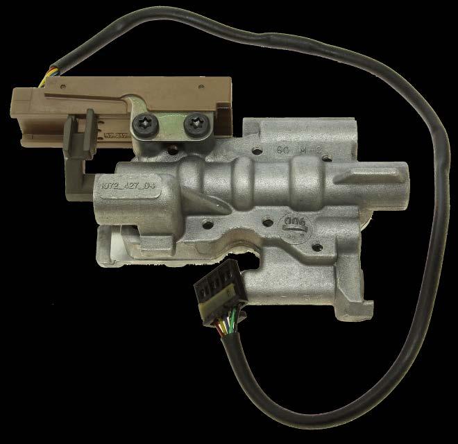
, secondary pulley pressure solenoid (PCC), and forward and reverse clutch apply")

22 The valve body has five solenoids: a main pressure control solenoid (PCA-A), torque converter clutch solenoid (TCC), primary pulley pressure solenoid (PCB), secondary pulley pressure solenoid (PCC), and forward and reverse clutch apply solenoid (PCD). All solenoids measure at 5.4 Ohms. 1. PCA Mainline Pressure Solenoid PCB Primary Variator Pressure PCC Secondary Variator Pressure PCD Forward and Reverse Clutch TCC Application Pressure TCC Solenoid Identification


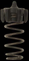
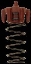
23 Always remove the solenoids to inspect the solenoid screens. Replace if torn or damaged Solenoid Identification (continued)


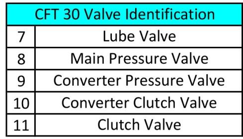
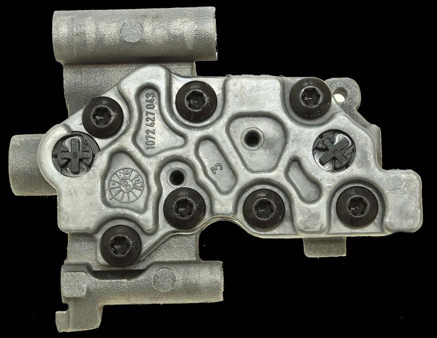
24 The TCM is mounted to the valve body (Mechatronic) Valve body identification


25 Valve body identification Black Green Red Small parts identification in the channel casting

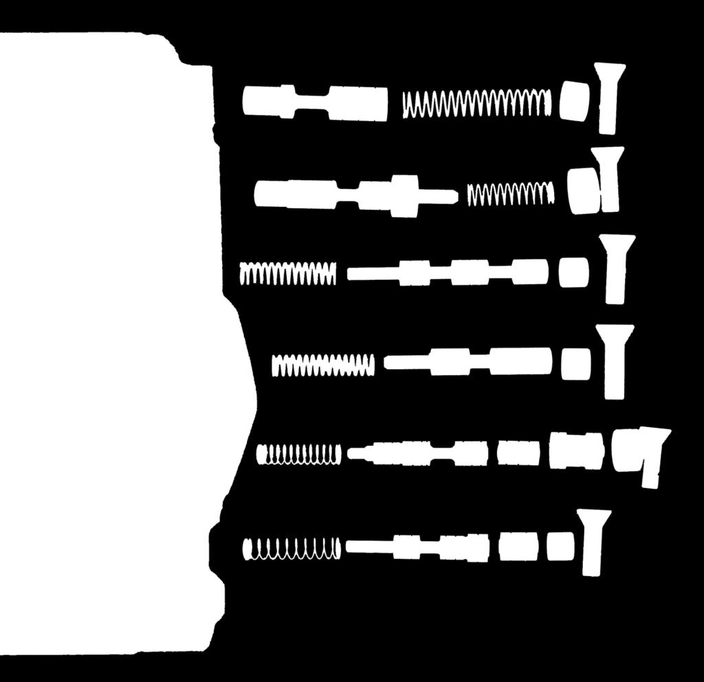
26 Valve body identification

27 Valve body identification


28 Manual Valve body identification Check valves push out from the other side of cover


29 No TCC Operation During the rebuild process you may not notice the input shaft O-ring is missing. The vehicle may have come in with a no torque converter clutch operation or a DTC related to the torque converter operation. Make sure to reinstall the input shaft O-ring on the end of the shaft. Make sure to reinstall the input shaft O-ring on the end of the shaft. Ford # 5F9Z- 7H4977-EA

30 Noises While Driving Use the following procedure to identify and repair specific CVT transmission noises. It s important to understand normal operating characteristics of the CVT, what type, location, and speeds of noise. 1. For whine/thump/knock noise in park or neutral, go to Step For tick noise on deceleration from 20 MPH (32 Km/h) to a stop, go to Step For whine noise on deceleration, go to Step 3.


31 Noises While Driving (continued) Step 1: Whine / thump / knock in park and neutral with engine running that goes away when vehicle is put into drive. Noise may come back when vehicle starts to move. This may be caused by machining of the input shaft or flat spots on the roller bearing. For diagnosis first use chassis ears to pinpoint the noise to transaxle area. If the noise is from the transaxle, monitor Turbine Shaft Speed (TSS_SRC) PID using scan tool. If the noise goes away as TSS_SRC goes to 0, when vehicle is put in gear, replace input shaft and bearing. Check for flat spots on the roller bearing Check the machining of the input shaft


 and road test.")

32 Noises While Driving (continued) Step 2: Tick noise on deceleration from 20 MPH (32 Km/h) to a stop. This may be caused by the differential ring gear. For front wheel drive (FWD), if the noise is isolated to the final drive area of the transmission, replace the differential assembly and transfer gear. If the vehicle is an all wheel drive (AWD), remove the power transfer unit (PTU) assembly, reinstall the halfshafts, disconnect the differential electronic module (DEM) and road test. If the noise goes away, the condition is isolated to the AWD system (not CVT related). If the noise is still present, replace the transaxle differential and transfer gear and shim the differential assembly and set proper preload. All replacement differential assemblies are serviced with bearings installed. AWD differentials are serviced with the inner seal installed. Outer bearing races are not packaged with replacement differential/bearing assemblies and will also require replacement.
33 Noises While Driving (continued) Step 3: Gear whine during coast down or deceleration. This may be caused by the transfer gear assembly. If noise follows the criteria below, replace the transfer gear. noise from MPH (68-56 Km/h) (loudest around 37 MPH (59 Km/h)) noise from MPH (51-40Km/h) (loudest around 27 MPH (43 Km/h)) noise from MPH (18-26 Km/h) (loudest around 15 MPH (24 Km/h))
34 Thank you to our Co- Sponsors
35 Today s Presentation Sponsored By: Thank You For Attending
DIAGNOSIS AND TESTING
 307-01-1 Automatic Transaxle/Transmission 307-01-1 DIAGNOSIS AND TESTING Pinpoint Tests OSC Equipped Vehicle Special Tool(s) Transmission Fluid Pressure Gauge 307-004 (T57L-77820-A) Special Tool(s) MLP-TR
Diagnostic Trouble Code (DTC) Charts
 Charts") SECTION 307-01: Automatic Transaxle/Transmission 5R55S 2009 Mustang Workshop Manual DIAGNOSIS AND TESTING Procedure revision date: 06/30/2009 Diagnostic Trouble Code (DTC) Charts DTC Chart **May also be
SECTION 307-01: Automatic Transaxle/Transmission 5R55S 2009 Mustang Workshop Manual DIAGNOSIS AND TESTING Procedure revision date: 06/30/2009 Diagnostic Trouble Code (DTC) Charts DTC Chart **May also be
FORD 6R80 UPDATES Presented by: David Chalker ATRA Technical Advisor 6R80
 FORD UPDATES Presented by: David Chalker ATRA Technical Advisor Welcome To Today s Presentation Sponsored By: Any Questions Or Comments Please Send Emails To webinars@atra.com Any Questions That You
Pinpoint Tests OSC Equipped Vehicle
 SECTION 307-01: Automatic Transaxle/Transmission 5R55S 2009 Mustang Workshop Manual DIAGNOSIS AND TESTING Procedure revision date: 11/19/2008 Pinpoint Tests OSC Equipped Vehicle Special Tool(s) 73 III
2002 Explorer/Mountaineer Workshop Manual
 Page 1 of 20 SECTION 307-01: Automatic Transmission - 5R55W/S 2002 Explorer/Mountaineer Workshop Manual DIAGNOSIS AND TESTING Procedure revision date: 10/20/2004 Pinpoint Tests OSC Equipped Vehicles Special
DIAGNOSIS AND TESTING
 307-01-1 Automatic Transmission 5R55S 307-01-1 DIAGNOSIS AND TESTING Transmission Connector Layouts Connector Reference and Terminal Readings Powertrain Control Module (PCM) C175b 1 Shift Solenoid A (SSA)
DIAGNOSIS AND TESTING
 307-01-1 Automatic Transaxle/Transmission 307-01-1 DIAGNOSIS AND TESTING Diagnostic Trouble Code Charts Diagnostic Trouble Code Chart P0102, MAF MAF concerns MAF system High/low EPC REFER to the P0103,
ATRA WEBINAR Chrysler CVT-2 Introduction
 ATRA WEBINAR Chrysler CVT-2 Introduction Sponsored By: Presented by: Steve Garrett ATRA Today s Presentation Sponsored By: Lwiggins@ATRA.com Connections Handout Questions Survey Thanks A special thanks
There s a Profit to Be Made
 There s a Profit to Be Made by Hank Blair members.atra.com I ve heard from shops who claim the Ford CFT 30 is too hard to work on or they can t get parts. Well, things are changing; the parts are becoming
Felkodslista Allison MY 09 med översättningstabell för Scania
 Felkodslista Allison MY 09 med översättningstabell för Scania (På Scania presenteras Felkoder i decimal format i IVD displayen.) Allison DTC number Scania display code (Hex) Scania display code (Dec) Description
2006 F-150/Mark LT Workshop Manual
 Page 1 of 14 SECTION 307-01: Automatic Transaxle/Transmission 4R70E/4R75E DIAGNOSIS AND TESTING Procedure revision date: 09/26/2008 Pinpoint Tests OSC Equipped Vehicle Printable View (485 KB) Special Tool(s)
ZF4HP16. Technical Bulletin # Signal Combination L1 L2 L3 L4 P R N D
 Transmission: Subject: Application: Issue Date: Technical Bulletin # 1308 ZF4HP16 Electronical Components Description 2005 Suzuki Forenza L4-2.0L February, 2010 ZF4HP16 Electronical Components Description
Special Testing Procedures
 SECTION 307-01: Automatic Transaxle/Transmission 5R55S 2009 Mustang Workshop Manual DIAGNOSIS AND TESTING Procedure revision date: 06/30/2009 Special Testing Procedures Special Tool(s) Air Test Plate and
DIAGNOSIS AND TESTING
 307-01-1 Automatic Transaxle/Transmission 307-01-1 DIAGNOSIS AND TESTING Transmission Connector Layouts Connector Reference and Terminal Readings Powertrain Control module (PCM) 1 Pressure control solenoid
DIAGNOSIS AND TESTING Procedure revision date: 09/23/2004
 2002 Excursion Subarticles Report a problem with this article On-Board Diagnostics with Scan Tool Transmission Drive Cycle Test After On-Board Diagnostics Before Pinpoint Tests Diagnostic Trouble Code
P0777-SECONDARY PRESSURE SOLENOID STUCK ON (LOW PRESSURE)
") 009 - MK - JEEP COMPASS/PATRIOT -.0L 4 CYL DOHC 6V DUAL V.V.T. P0777-SECONDARY STUCK ON (LOW ) / LINE SECONDARY ON/OFF 3 4 T0 DG/LB T9 T9 T60 YL/DB YL/LB YL/GY C C 3 C 4 C LINE SECONDARY ON/OFF MODULE-
009 - MK - JEEP COMPASS/PATRIOT -.0L 4 CYL DOHC 6V DUAL V.V.T. P0777-SECONDARY STUCK ON (LOW ) / LINE SECONDARY ON/OFF 3 4 T0 DG/LB T9 T9 T60 YL/DB YL/LB YL/GY C C 3 C 4 C LINE SECONDARY ON/OFF MODULE-
SECTION Electronic Engine Controls
 303-14-i Electronic Engine Controls 303-14-i SECTION 303-14 Electronic Engine Controls CONTENTS PAGE DIAGNOSIS AND TESTING Electronic Engine Controls... 303-14-2 DTC Charts... 303-14-2 303-14-2 Electronic
Toyota A750 E/F A760 E/F A761 Introduction. Sponsored By: Presented by: Steve Garrett ATRA
 Toyota A750 E/F A760 E/F A761 Introduction Sponsored By: Presented by: Steve Garrett ATRA Today s Presentation Sponsored By: Lwiggins@ATRA.com Connections Handout Questions Survey Toyota A750 E/F Common
SECTION 5 DIAGNOSTIC TROUBLE CODES (DTC)
") 5 1. DTC MEMORY SECTION 5 Diagnostic Trouble Codes (DTCs) are logged in a list in TCM memory. The DTCs contained in the list have information recorded as shown in Table 5 1 (DTC example). The TCM is capable
5 1. DTC MEMORY SECTION 5 Diagnostic Trouble Codes (DTCs) are logged in a list in TCM memory. The DTCs contained in the list have information recorded as shown in Table 5 1 (DTC example). The TCM is capable
Torque Converter Clutch (TCC) Solenoid
 Solenoid") Torque Converter Clutch (TCC) Solenoid The torque converter clutch (TCC) solenoid provides torque converter clutch control by shifting the converter clutch control valve to apply or release the TCC. PINPOINT
Torque Converter Clutch (TCC) Solenoid The torque converter clutch (TCC) solenoid provides torque converter clutch control by shifting the converter clutch control valve to apply or release the TCC. PINPOINT
SHIFT SELECTOR OPERATION AND CODE MANUAL
 SHIFT SELECTOR OPERATION AND MANUAL How to use the shift selector to read oil level and diagnostic codes on 3000/4000 Series Allison transmissions P.O. Box 894, Speed Code 462-470-PF3 Indianapolis, Indiana
DIAGNOSIS AND TESTING
 204-04-1 Wheels and Tires 204-04-1 DIAGNOSIS AND TESTING Tire Pressure Monitoring System Special Tool(s) Vehicle Communication Module (VCM) and Integrated Diagnostic System (IDS) software with appropriate
ANTI-LOCK BRAKING SYSTEM (ABS)
") 35B-1 GROUP 35B ANTI-LOCK BRAKING SYSTEM (ABS) CONTENTS GENERAL DESCRIPTION 35B-2 35B-5 INTRODUCTION TO 35B-5 ABS DIAGNOSTIC TROUBLESHOOTING STRATEGY 35B-5 DIAGNOSTIC FUNCTION 35B-6 DIAGNOSTIC TROUBLE
35B-1 GROUP 35B ANTI-LOCK BRAKING SYSTEM (ABS) CONTENTS GENERAL DESCRIPTION 35B-2 35B-5 INTRODUCTION TO 35B-5 ABS DIAGNOSTIC TROUBLESHOOTING STRATEGY 35B-5 DIAGNOSTIC FUNCTION 35B-6 DIAGNOSTIC TROUBLE
PRE CHECK DI 456. w/ Tachometer. w/o Tachometer. Hand held Tester AUTOMATIC TRANSMISSION (A340E, A340F) 2003 TOYOTA TACOMA (RM1002U) D10837 D00729
 2003 TOYOTA TACOMA (RM1002U) D10837 D00729") DI456 w/ Tachometer w/o Tachometer D10837 PRECHECK DI8Z403 1. DIAGNOSIS SYSTEM (a) Description When troubleshooting OBD II vehicles, the only difference from the usual troubleshooting procedure is that
DI456 w/ Tachometer w/o Tachometer D10837 PRECHECK DI8Z403 1. DIAGNOSIS SYSTEM (a) Description When troubleshooting OBD II vehicles, the only difference from the usual troubleshooting procedure is that
LX AUTOMATIC TRANSMISSION NAG1 - SERVICE INFORMATION TABLE OF CONTENTS
 LX AUTOMATIC TRANSMISSION NAG1 - SERVICE INFORMATION 21-495 AUTOMATIC TRANSMISSION NAG1 - SERVICE INFORMATION TABLE OF CONTENTS page AUTOMATIC TRANSMISSION NAG1 - SERVICE INFORMATION DESCRIPTION...496
2002 Ford Explorer AUTOMATIC TRANSMISSIONS' '5R55W/S Diagnosis 2002 AUTOMATIC TRANSMISSIONS. 5R55W/S Diagnosis
 2002 AUTOMATIC TRANSMISSIONS 5R55W/S Diagnosis APPLICATION WARNING: Vehicles are equipped with Supplemental Inflatable Restraint (SIR) system. When servicing vehicle, use care to avoid accidental air bag
07 GRP04_All Transmissions.xls
 Component/ Fault Monitor Strategy Malfunction Threshold Secondary Parameters / Time MIL Extra System Code Description Criteria Value Enable Conditions Required Illumin. Prep TCM, Internal Fault P0605 ROM
TROUBLE SHOOTING > SYMPTOM DIAGNOSIS > SOME OR ALL SHIFTS MISSING TROUBLE SHOOTING > SYMPTOM DIAGNOSIS > NO 1-2, 2-3 OR 3-4 UPSHIFT (AUTOMATIC)
") AUTOMATIC TRANSMISSION - DIAGNOSIS - E4OD A/T TROUBLE SHOOTING 1997 Ford Pickup 7.3L Eng F350 Question: overdrive off light is on steady TROUBLE SHOOTING > SYMPTOM DIAGNOSIS Question: Repeat OD planetary
AUTOMATIC TRANSMISSION - DIAGNOSIS - E4OD A/T TROUBLE SHOOTING 1997 Ford Pickup 7.3L Eng F350 Question: overdrive off light is on steady TROUBLE SHOOTING > SYMPTOM DIAGNOSIS Question: Repeat OD planetary
Zoom and Print Options
 Vehicle» A L L Diagnostic Trouble Codes ( DTC )» Testing and Inspection» P Code Charts» P0707» CVT Automatic Transaxle P0707-TRANSMISSION RANGE SENSOR CIRCUIT LOW http://repair.alldata.com/alldata/article/display.action?componentid=3926&itypeid=423&nonstandardid=1733324&vehicleid=42661&windowname=m
TRACTION CONTROL SYSTEM (TCL)
") 35C-1 GROUP 35C TRACTION CONTROL SYSTEM (TCL) CONTENTS GENERAL DESCRIPTION 35C-2 DIAGNOSIS 35C-4 INTRODUCTION TO TRACTION CONTROL SYSTEM DIAGNOSIS 35C-4 TCL DIAGNOSTIC TROUBLESHOOTING STRATEGY 35C-4 DIAGNOSTIC
35C-1 GROUP 35C TRACTION CONTROL SYSTEM (TCL) CONTENTS GENERAL DESCRIPTION 35C-2 DIAGNOSIS 35C-4 INTRODUCTION TO TRACTION CONTROL SYSTEM DIAGNOSIS 35C-4 TCL DIAGNOSTIC TROUBLESHOOTING STRATEGY 35C-4 DIAGNOSTIC
1998 Ford F Diagnostics > Diagnostic Routines > Powertrain > Automatic Transmission > A... Page 1 of 63
 1998 Ford F-150 - Diagnostics > Diagnostic Routines > Powertrain > Automatic Transmission > A... Page 1 of 63 1998 Ford F-150 : Diagnostics > Diagnostic Routines > Powertrain > Automatic Transmission >
DIAGNOSIS AND TESTING
 307-01B-1 DIAGNOSIS AND TESTING Special Testing Procedures The special tests are designed to aid the technician in diagnosing the hydraulic and mechanical portion of the transmission. Engine Idle speed
Welcome To Today s Presentation Sponsored By:
 Welcome To Today s Presentation Sponsored By: Any Questions Or Comments Please Send Emails To webinars@atra.com Any Questions That You May Have During The Webinar Please Feel Free To Text Them In At Any
AUTOMATIC TRANSMISSION (DIAGNOSTICS)
") AUTOMATIC TRANSMISSION (DIAGNOSTICS) Basic Diagnostic Procedure 1. Basic Diagnostic Procedure A: PROCEDURE Is the unit that is thought to Go to step 2. influence the AT problem working properly? 1 CHECK
AUTOMATIC TRANSMISSION (DIAGNOSTICS) Basic Diagnostic Procedure 1. Basic Diagnostic Procedure A: PROCEDURE Is the unit that is thought to Go to step 2. influence the AT problem working properly? 1 CHECK
Technical Bulletin Listing 2008
 Technical Bulletin Listing 2008 December, 2008 Transmission Bulletin # # Pages Subject January 5R55N/S/W 1149 1 Soft 1-2, 2-3 Shift, Possible Skipped Shift Honda/Acura 1150 1 Filling and Checking the Oil
AUTOMATIC TRANSMISSION (DIAGNOSTICS) AT
 AT") AUTOMATIC TRANSMISSION (DIAGNOSTICS) AT Page 1. Basic Diagnostic Procedure...2 2. Check List for Interview...4 3. General Description...5 4. Electrical Components Location...7 5. Transmission Control Module
AUTOMATIC TRANSMISSION (DIAGNOSTICS) AT Page 1. Basic Diagnostic Procedure...2 2. Check List for Interview...4 3. General Description...5 4. Electrical Components Location...7 5. Transmission Control Module
05/01/06 1er mai 2006 Cruise Control - Diagnostic Updates General Service Procedure Service Procedure Speed Control Diagnostic Tips Additional
 05/01/06 1er mai 2006 General Service Procedure Service Procedure Speed Control Diagnostic Tips Additional Reference Information SPEED CONTROL DIAGNOSTICS - W/O SCP FORD: 2000-2003 Escort 2000-2004 Crown
Powertrain DTC Summaries EOBD
 Powertrain DTC Summaries Quick Reference Diagnostic Guide Jaguar X-TYPE 2.0 L 2002.25 Model Year Refer to page 2 for important information regarding the use of Powertrain DTC Summaries. Jaguar X-TYPE 2.0
P0706-TRANSMISSION RANGE SENSOR RATIONALITY
 Page 1 of 7 28 - DTC-Based Diagnostics/MODULE, Powertrain Control (PCM), 545RFE/Diagnosis and Testing P0706-TRANSMISSION RANGE SENSOR RATIONALITY Special Tools: Click to display a list of tools used in
27 E. Front wheel drive. 1. Transmission Description (Ford Focus 2000 only) 4 4 Speed Transmission F
 4 4 Speed Transmission F") 1. Transmission Description (Ford Focus 2000 only) 4 4 Speed Transmission F Front wheel drive 27 E Maximum input torque after torque converter: 270 Lb-ft (365 N-m) Fully Electronic control Note: Mazda
1. Transmission Description (Ford Focus 2000 only) 4 4 Speed Transmission F Front wheel drive 27 E Maximum input torque after torque converter: 270 Lb-ft (365 N-m) Fully Electronic control Note: Mazda
DIAGNOSIS AND TESTING
 307-01-1 Automatic Transaxle/Transmission 307-01-1 DIAGNOSIS AND TESTING Special Testing Procedures Special Tool(s) Air Test Plate, Transmission 307-405 Transmission Fluid Pressure Gauge 307-004 (T57L-77820-A)
HV: Cooling Fan Clutch
 2009 PCED Gasoline Engines SECTION 5: Pinpoint Tests Procedure revision date: 12/10/2008 HV: Cooling Fan Clutch HV: Introduction HV1 CHECK FOR DIAGNOSTIC TROUBLE CODES (DTCS) Are DTCs P0480, P0483 or P0528
TRANSMISSION DIAGNOSTIC PARAMETERS
 TCM, Internal P0605 ROM checksum or RAM error Calculated checksum differs from stored. Ignition ON Number of failed calculations: 2 Lost communication with ECM (Engine) U0100 Frame missing from ECM Detect
ALLISON IDENTIFICATION TAG
 ALLISON IDENTIFICATION TAG 1000 2000 2000MH 2400 Heavy duty automatic transmission with parking pawl. maximum GVW = 19850 lb. Heavy duty automatic transmission without parking pawl. maximum GVW = 30000
Table of Contents INTRO
 GENERAL ALL Wheel Drive Systems General System Overview...2 Transfer Coupling...3 Diagnostics, Tire Wear, Codes...4 Rolling Circumference Test...5 Getrag 760 T-Case Introduction and Service Information...6
C6 Corvette DIC Codes
 C6 Corvette DIC Codes B0159 Outside Air Temp Sensor B2910 Steering Column Lock Password Incorrect B0164 Pass Compartment Temp Sensor B2981 Right Front Door Handle Switch B0174 Output Air Temp Sensor 1
Technical Bulletin Listing 2010
 Technical Bulletin Listing 2010 January, 2010 Transmission Bulletin # # Pages Subject January Allison LCT 1000 1300 1 Sets P0872, No 4th, 3rd Gear Start 4L80E 1301 4 Shift Shuttle/No Line Rise RE4F04A
Technical Bulletin Listing
 Transmission Bulletin # # Pages Subject Technical Bulletin Listing January, 2007 January U140E, U140F 829A 2 Sprag Rotation V4A51 1054 1 No Power Above 3500 RPM 4T60E 1055 1 Neutral/Shudder During the
DP: Vehicle Speed Sensor (VSS)/Transfer Case Speed Sensor (TCSS) DP: Introduction
/Transfer Case Speed Sensor (TCSS) DP: Introduction") PPT DP: VEHICLE SPEED SENSOR... PPT DP: VEHICLE SPEED SENSOR ()/TRANSFER CASE SPEED SENSOR (TCSS) (GASOLINE ENGINES) 2005 PCED Gasoline Engines SECTION 5: Pinpoint Tests Procedure revision date: 03/30/2005
PPT DP: VEHICLE SPEED SENSOR... PPT DP: VEHICLE SPEED SENSOR ()/TRANSFER CASE SPEED SENSOR (TCSS) (GASOLINE ENGINES) 2005 PCED Gasoline Engines SECTION 5: Pinpoint Tests Procedure revision date: 03/30/2005
2001 Chevrolet Corvette ACCESSORIES & EQUIPMENT Cruise Control Systems - Corvette
 2001 ACCESSORIES & EQUIPMENT Cruise Control Systems - Corvette DESCRIPTION Cruise control is a speed control system that maintains a desired vehicle speed under normal driving conditions. Steep grades
P0750-LR SOLENOID CIRCUIT
 9 - JS - DGE AVENGER -.L CYL DOHC V DUAL V.V.T. P-LR CIRCUIT BATT A B(+) CONTROL OUTPUT ELECTRONICS TOTALLY INTEGRATED POWER C T S T C T C T S T - - UD / T T YL/TN YL/DG T9 DG/TN T9 T T9 T YL/DB DG/WT
Technical Bulletin Listing 2008
 Technical Bulletin Listing 2008 April, 2008 Transmission Bulletin # # Pages Subject January 5R55N/S/W 1149 1 Soft 1-2, 2-3 Shift, Possible Skipped Shift Honda/Acura 1150 1 Filling and Checking the Oil
1995 Town Car/Crown Victoria/Grand Marquis
 Page 1 of 11 PINPOINT TEST A: SHIFT SOLENOIDS Pinpoint Test A Shift Solenoids DTCs: P0781, P0782, P0783 Shift Errors P0750, P0755 Solenoid Circuit Failures P0751, P1751 Shift Solenoid. 1 Malfunction P0756,
Variable Geometry Turbocharger (VGT) Actuator Connector
 Actuator Connector") Page 1 of 5 Year = 2006 Model = F-Super Duty Engine = VIN = IDS Version = 77A.05 (IDS-77A.05) Variable Geometry Turbocharger (VGT) Output Circuit Function The VGT actuator is a variable position valve
Page 1 of 5 Year = 2006 Model = F-Super Duty Engine = VIN = IDS Version = 77A.05 (IDS-77A.05) Variable Geometry Turbocharger (VGT) Output Circuit Function The VGT actuator is a variable position valve
P2284 REQUESTED INFORMATION. Pinpoint Test Ao: Injector Control Pressure Too High. Print Ford Pickup 6.0L Eng F250 Super Duty.
 Print 2004 Ford Pickup 6.0L Eng F250 Super Duty P2284 REQUESTED INFORMATION Pinpoint Test Ao: Injector Control Pressure Too High Introduction Signal Function The injector control pressure is determined
Transmission Electronic Control System
 SECTION 307-01: Automatic Transaxle/Transmission 5R55S 2009 Mustang Workshop Manual DESCRIPTION AND OPERATION Procedure revision date: 05/23/2008 Transmission Electronic Control System Electronic System
 Page 1 of 7 PINPOINT TEST F: TURBINE SHAFT SPEED (TSS) SENSOR AND OUTPUT SHAFT SPEED (OSS) SENSOR NOTE: Refer to the OSS-Sensor or TSS-Sensor Connector illustration preceding these pinpoint tests. CONDITIONS
INTRODUCTION PRELIMINARY DIAGNOSIS
 NO: 21-11-98 SUBJECT: Transmission Simulator Diagnostic Tool DATE: Dec. 11, 1998 NOTE: THIS INFORMATION APPLIES TO VEHICLES EQUIPPED WITH A 45RFE TRANSMISSION. DISCUSSION: A new transmission simulator
CVT VALVE BODY COMMON WARRANTY COMPLAINTS AND TIPS
 CVT VALVE BODY COMMON WARRANTY COMPLAINTS AND TIPS Disclaimer: Please consult with a qualified auto technician before attempting to perform any diagnosis, repairs, or modifications based on this guide.
DI 244 DIAGNOSTICS AUTOMATIC TRANSMISSION DIB30 01 PRE CHECK
 DI244 DIAGNOSTICS PRECHECK DIB3001 1. DIAGNOSIS SYSTEM (a) Description When troubleshooting OBD II vehicles, the only difference from the usual troubleshooting procedure is that you connect to the vehicle
MEDIUM DUTY TRUCK. Presented By. ATSG s PETE LUBAN
 MEDIUM DUTY TRUCK Presented By ATSG s PETE LUBAN 1/3/2M WWW.ATSG.COM 2/3/1M 3/3 1000/2000 SERIES Transmission code identification PPT 1 0 0 0 MHS HS Highway Series MHS Motor Home Series EVS Emergency Vehicle
SECTION Multifunction Electronic Modules
 419-10-i Multifunction Electronic Modules 419-10-i SECTION 419-10 Multifunction Electronic Modules CONTENTS PAGE DIAGNOSIS AND TESTING Smart Junction Box (SJB)... 419-10-2 Principles of Operation... 419-10-2
Technical Bulletin Listing 2009
 Technical Bulletin Listing 2009 May, 2009 Transmission Bulletin # # Pages Subject January U140E/U241E 1225 1 Harsh 2-3 Shift After Overhaul GM MP T-Case 1226 10 Introduction 6T70/75 1227 1 Transfer Bolt
AUTO TRANS OVERHAUL - V.A.G. 01V Article Text 1998 Volkswagen Passat This file passed thru Volkswagen Technical Site -
 AUTO TRANS OVERHAUL - V.A.G. 01V Article Text 1998 Volkswagen Passat This file passed thru Volkswagen Technical Site - http://volkswagen.msk.ru ARTICLE BEGINNING 1997-98 AUTOMATIC TRANSMISSIONS Volkswagen/Audi
DIAGNOSIS AND TESTING
 206-09-1 Vehicle Dynamic Systems 206-09-1 DIAGNOSIS AND TESTING Anti-Lock Control Traction Control and Stability Assist Special Tool(s) Principles of Operation 73III Automotive Meter 105-R0057 or equivalent
DIAGNOSIS AND TESTING
 204-04-1 Wheels and Tires 204-04-1 DIAGNOSIS AND TESTING Tire Pressure Monitoring System Special Tool(s) Principles of Operation Activation Tool, Tire Pressure Monitor 204-363 Digital Tire Gauge 204-354
2001 FORESTER SERVICE MANUAL QUICK REFERENCE INDEX
 2001 FORESTER SERVICE MANUAL QUICK REFERENCE INDEX TRANSMISSION SECTION This service manual has been prepared to provide SUBARU service personnel with the necessary information and data for the correct
DESCRIPTION. Chrysler NCV3 Service Info Section 08 > Electronic Modules > MODULE, Transmission Control Information
 DESCRIPTION The transmission control module (TCM) receives, processes and sends various digital and analog signals related to the automatic transmission. In addition, it processes information received
Visctronic Drive Fan (VDF )
") Page 1 of 9 Year = 2006 Model = F-Super Duty Engine = VIN = IDS Version = t Available Visctronic Drive Fan (VDF ) WARNING: To avoid the possibility of personal injury or damage to the vehicle, do not operate
Page 1 of 9 Year = 2006 Model = F-Super Duty Engine = VIN = IDS Version = t Available Visctronic Drive Fan (VDF ) WARNING: To avoid the possibility of personal injury or damage to the vehicle, do not operate
AISIN WARNER. 1. With the selector lever in Park, start the engine and warm it to operating temperature.
 AISIN WARNER 249 Manual Code Retrieval Preliminary Test: 1. With the selector lever in Park, start the engine and warm it to operating temperature. 2. Turn the ignition switch to the Off position, then
1 of 1 7/1/17, 2:02 PM. Air Cleaner Assembly Replacement ALLDATA, LLC. All Rights Reserved. (Version )
") Air Cleaner Housing Service and Repair, Removal and Replacement: Ai... http://repair.alldata.com/alldata/article/display.action?componentid=367... 1 of 1 7/1/17, 2:02 PM Air Cleaner Assembly Replacement
Air Cleaner Housing Service and Repair, Removal and Replacement: Ai... http://repair.alldata.com/alldata/article/display.action?componentid=367... 1 of 1 7/1/17, 2:02 PM Air Cleaner Assembly Replacement
DESCRIPTION AND OPERATION > TRANSAXLE DESCRIPTION
 Page 1 of 10 2006 Mercury Montego 3.0L Eng Premier Service Manual: AUTOMATIC TRANSMISSION - CVT Print Date: DESCRIPTION AND OPERATION > TRANSAXLE DESCRIPTION This transaxle represents the start of a new
Service Bulletin Buses
 Prevost Saint-Nicolas, Quebec, Canada Service Bulletin Buses Date Group No. Release Page 6.2010 364 00 1(12) Vehicle Electronic Control Unit (VECU) MID 144, Diagnostic Trouble Code (DTC), Guide Vehicle
ATASA 5 th Study Guide. Be Certain to Read the Summary Chapter 42 Pages Automatic Transmissions & Transaxle Service 31 Points
 ATASA 5 th Study Guide Be Certain to Read the Summary Chapter 42 Pages 1245 1270 Automatic Transmissions & Transaxle Service 31 Points 1. Prior to beginning any service work on a transmission, it correctly
DPS6 Internal Operation
 DPS6 Internal Operation Presented by: Bill Brayton ATRA Senior Research Technician Welcome To Today s Presentation Sponsored By: Any Questions Or Comments Please Send Emails To webinars@atra.com Any Questions
P0760-OD SOLENOID CIRCUIT
 - JC - DGE JOURNEY -.5L V6 V MPI - HIGH OUTPUT P6- CIRCUIT BATT A RELAY-PCM MULE- TOTALLY INTEGRATED POWER A FUSE J A 6 C T6 6 C T6 D C5 T6 S T6 6 L/R / /TRS EMCC VFS C LR UD 6 5 T6 T6 T6 T5 T T T T YL/TN
ME: Fuel Pump Control - High Pressure Fuel Injection Pump
 Page 1 of 6 2008 Ford F-250 Super Duty : Diagnostics > 6.4L Diesel > Pinpoint Tests > ME: Fuel Pump Control - High Pressure Fuel Injection Pump ME: Fuel Pump Control - High Pressure Fuel Injection Pump
AUTOMATIC TRANSMISSIONS. General Motors Corp. Hydra-Matic 4L60-E Overhaul
 1997-98 AUTOMATIC TRANSMISSIONS General Motors Corp. Hydra-Matic 4L60-E Overhaul APPLICATION TRANSMISSION APPLICATIONS Application Corvette Transaxle 4L60-E IDENTIFICATION The 4L60-E transmission can be
Diagnostic Trouble Codes (continued) GM Specific Codes
 GM Specific Codes") 85 GM Specific Codes P11XX Fuel and Air Metering P1106 MAP Sensor Circuit Intermittent High Voltage P1107 MAP Sensor Circuit Intermittent Low Voltage P1108 BARO to MAP Signal Comparison Too High P1111
85 GM Specific Codes P11XX Fuel and Air Metering P1106 MAP Sensor Circuit Intermittent High Voltage P1107 MAP Sensor Circuit Intermittent Low Voltage P1108 BARO to MAP Signal Comparison Too High P1111
AUTOMATIC TRANSMISSIONS Mitsubishi F3A20 Series TRANSMISSION APPLICATION TABLE
 Article Text ARTICLE BEGINNING AUTOMATIC TRANSMISSIONS Mitsubishi F3A20 Series APPLICATION TRANSMISSION APPLICATION TABLE Vehicle Application Transmission Model Colt 3-Speed (1990-94)... F3A21 Colt Vista
2002 F-150 Workshop Manual
 Page 1 of 23 SECTION 310-03: Speed Control 2002 F-150 Workshop Manual DIAGNOSIS AND TESTING Procedure revision date: 08/07/2006 Speed Control Refer to Wiring Diagrams Cell 31, Speed Control for schematic
2011 Dodge or Ram Truck RAM 3500 Truck 4WD L6-6.7L DSL Turbo
 1 of 10 10/14/2013 9:23 AM 2011 Dodge or Ram Truck RAM 3500 Truck 4WD L6-6.7L DSL Turbo Vehicle» A L L Diagnostic Trouble Codes ( DTC )» Testing and Inspection» P Code Charts» P0732 P0732-GEAR RATIO ERROR
Technical Service Bulletin
 Subject ATA SOLENOID DIAGNOSTIC CODES P0740, P0741, P0742, P0743, P0746, P0748, P0750, P0755, P0760, P0765, P0770 Date Model [X] PARTS MANAGER JANUARY, 2006 1999~ SONATA, 2001~ ELANTRA, SANTA FE & XG,
2006trans13_b.doc ACCEPTABLE OPERATING RANGE AND RATIONALITY SENSED PARAMETER FAULT CODE PRIMARY MALF DETECTION PARAMETERS
 S S DE ACTIONS S Over Temperature P0218 High transmission fluid temperature for long period of time Trans Temp > 130 C. 8.0V < Ignition < 18.0V -39 C. < Trans Temp < 149 C. for 5 sec 600 sec FA Trans Temp
Printable View Page 1 of 18 11/26/2013 Year = 2011 Model = E
 Page 1 of 18 Year = 2011 Model = Escape Engine = VIN = IDS Version = t Available Misfire Detection Monitor WARNING: Crown Victoria Police Interceptor vehicles equipped with fire suppression system, refer
Technical Bulletin Listing 2009
 Technical Bulletin Listing 2009 Transmission Bulletin # # Pages Subject January U140E/U241E 1225 1 Harsh 2-3 Shift After Overhaul GM MP T-Case 1226 10 Introduction 6T70/75 1227 1 Transfer Bolt Eliminated
07 GRP13_4T80E LD8_L37.doc. Page 1 of 7
 Module Read Only Memory Module Not Programmed P0601 EPROM/Flash memory corruption (Incorrect program/calibrations checksum) ROM fail count > 5 None Immediate P0602 Non-programmed TCM (calibrations) KbCOND_NoStartCal
Powertrain DTC Summaries OBD II
 Powertrain DTC Summaries Quick Reference Diagnostic Guide Jaguar X-TYPE 2.5L and 3.0L 2002 Model Year Revised January, 2002: P0706, P0731, P0732, P0733, P0734, P0735, P0740, P1780 POSSIBLE CAUSES Revised
DISASSEMBLY AND ASSEMBLY
 307-01-1 Automatic Transaxle/Transmission 307-01-1 DISASSEMBLY AND ASSEMBLY Transaxle Special Tool(s) Dial Indicator Gauge With Holding Fixture 100-002 (TOOL-4201-C) Special Tool(s) Test Plate Screw Set,
G - TESTS W/CODES - 2.2L
 G - TESTS W/CODES - 2.2L 1994 Toyota Celica 1994 ENGINE PERFORMANCE Toyota 2.2L Self-Diagnostics Celica INTRODUCTION If no faults were found while performing F - BASIC TESTING, proceed with self-diagnostics.
ProECU Subaru DIT. DTC List 2012-onward Model Year. v1.0
 ProECU Subaru DIT DTC List 2012-onward Model Year v1.0 Engine DTC List P000A A CAMSHAFT POSITION SLOW RESPONSE (BANK 1) P000B B CAMSHAFT POSITION SLOW RESPONSE (BANK 1) P000C A CAMSHAFT POSITION SLOW RESPONSE
ENGINE (DIAGNOSTICS) EN(SOHC)
 EN(SOHC)") EN(SOHC) Page 1. Basic Diagnostic Procedure...2 2. Check List for Interview...4 3. General Description...6 4. Electrical Components Location...9 5. Engine Control Module (ECM) I/O Signal...22 6. Engine
EN(SOHC) Page 1. Basic Diagnostic Procedure...2 2. Check List for Interview...4 3. General Description...6 4. Electrical Components Location...9 5. Engine Control Module (ECM) I/O Signal...22 6. Engine
ProECU Subaru BRZ Toyota GT86 Scion FR-S
 ProECU Subaru BRZ Toyota GT86 Scion FR-S DTC List 2012-onward Model Year v1.0 Engine DTC List P000A Camshaft Position "A" - Timing Slow Response Bank 1 P000B Camshaft Position "B" - Timing Slow Response
Cruise Control Diagnosis
 1999 Pontiac Firebird Cruise Control Diagnosis Circuit Description The Cruise Control system is a speed control system that maintains a desired vehicle speed under normal driving conditions. The cruise
2003 CVT when used with 2.2L L61 engine in the Saturn ION TRANSMISSION DIAGNOSTIC PARAMETERS
 TCM Memory ROM P0601 The code is designed to verify ROM checksum at key up. TCM Not Programmed P0602 The code is designed to verify that the TCM has been programmed. TCM Long Term Memory Reset P0603 This
M: Fuel System M: Introduction
 Page 1 of 7 2011 PCED 6.7L Diesel SECTION 5: Pinpoint Tests Procedure revision date: 12/14/2010 M: Fuel System M: Introduction M1 CHECK FOR DIAGNOSTIC TROUBLE CODES (DTCS) te: Repair any fuel injector
P0750-LR SOLENOID CIRCUIT
 2008 Dodge Pickup 4.7L Eng R1500 P0750-LR SOLENOID CIRCUIT Circuit Schematic Fig 1: Transmission Solenoid/TRS Assembly Circuit Schematic Courtesy of CHRYSLER LLC Additional Wiring For complete wiring diagrams
2001 Dodge Durango ACCESSORIES & EQUIPMENT' 'Anti-Theft Systems - Dakota & Durango 2001 ACCESSORIES & EQUIPMENT
 DESCRIPTION VEHICLE THEFT SECURITY SYSTEM 2001 ACCESSORIES & EQUIPMENT Anti-Theft Systems - Dakota & Durango Vehicle Theft Security System (VTSS) provides perimeter protection against unauthorized use
DTC P1259: VTEC System Malfunction. Special Tools Required
 DTC P1259: VTEC System Malfunction Special Tools Required Pressure gauge adapter 07NAJ-P07010A A/T low pressure gauge w/panel 07406-0070300 A/T pressure hose 07406-0020201 A/T pressure hose, 2,210 mm 07MAJ-PY4011A
2003 F-Super Duty /Excursion Workshop Manual
 3//2011 SECTION 310-03: Speed Control 2003 F-Super Duty 250-550/Excursion Workshop Manual DIAGNOSIS AND TESTING Procedure revision date: 08/01/2006 Speed Control Printable View (331 KB) Refer to Wiring