Operating instruction. Butterfly valve. Translation of the original ENGLISH
|
|
|
- Edmund McDowell
- 5 years ago
- Views:
Transcription

1 Translation of the original Operating instruction Butterfly valve P D F a k 0 4 / 0 2 / ENGLISH GB
2 K I E S E L M A N N G m b H Paul-Kieselmann-Str Knittlingen ( +49(0) (0) info@kieselmann.de Copyright: KIESELMANN FLUID PROCESS GROUP
3 KIESELMANN GmbH Table of contents Table of contents 1 General informations Informations for your safety Marking of security instructions General designated use Personnel Modifications, spare parts, accessories General instructions Safety instructions Intended use General notes General safety instructions Delivery, transport and storage Delivery Transport Storage Specification Modular system Valve types Function and operation Description of function Dry running Control system and position indication Pneumatic valve activation Commissioning, service and maintenance Commissioning Installation instructions ATEX - Guidelines General welding guidelines Service Cleaning Technical data Butterfly valve / Intermediate flanged - butterfly valve Leakage - butterfly valves Disassembly and assembly Disassembly Assembly Drawings and dimensions Butterfly valve Intermediate flange-butterfly valves Leakage butterfly valve drive systems Wearing parts Butterfly valve Leakage - butterfly valves Intermediate - butterfly valve Malfunctions Classification Structure of order number Appendix Butterfly_valves_EN iii
4 Table of contents KIESELMANN GmbH 12.1 Declaration of incorporation iv Butterfly_valves_EN
5 KIESELMANN GmbH Operating instruction General informations 1 1 General informations 1.1 Informations for your safety We are pleased that you have decided for a high-class KIESELMANN product. With correct application and adequate maintenance, our products provide long time and reliable operation. Before installation and initiation, please carefully read this instruction manual and the security advices contained in it. This guarantees reliable and safe operation of this product and your plant respectively. Please note that an incorrect application of the process components may lead to great material damages and personal injury. In case of damages caused by non observance of this instruction manual, incorrect initiation, handling or external interference, guarantee and warranty will lapse! Our products are produced, mounted and tested with high diligence. However, if there is still a reason for complaint, we will naturally try to give you entire satisfaction within the scope of our warranty. We will be at your disposal also after expiration of the warranty. In addition, you will also find all necessary instructions and spare part data for maintenance in this instruction manual. If you don't want to carry out the maintenance by yourself, our KIESELMANN - service team will naturally be at your disposal. 1.2 Marking of security instructions Hints are available in the chapter "safety instructions" or directly before the respective operation instruction. The hints are highlighted with a danger symbol and a signal word. Texts beside these symbols have to be read and adhered to by all means. Please continue with the text and with the handling at the valve only afterwards. Symbol Signal word Meaning DANGER Imminent danger which will result severe personal injury or death. WARNING CAUTION NOTICE INFORMATION Imminent danger which may result severe personal injury or death. Dangerous situation which may cause slight personal injury or material damages. An harmful situation which may result in damages of the product itself or of adjacent vicinity. Marks application hints and other information which is particularly useful. 1.3 General designated use The fitting is designed exclusively for the purposes described below. Using the fitting for purposes other than those mentioned is considered contrary to its designated use. KIESELMANN cannot be held liable for any damage resulting from such use. The risk of such misuse lies entirely with the user. The prerequisite for the reliable and safe operation of the fitting is proper transportation and storage as well as competent installation and assembly. Operating the fitting within the limits of its designated use also involves observing the operating, inspection and maintenance instructions. 1.4 Personnel Personnel entrusted with the operation and maintenance of the tank safety system must have the suitable qualification to carry out their tasks. They must be informed about possible dangers and must understand and observe the safety instructions given in the relevant manual. Only allow qualified personnel to make electrical connections. Butterfly_valves_EN 5 / 35
6 1 General informations Operating instruction Betriebsanleitung 1.5 Modifications, spare parts, accessories Unauthorized modifications, additions or conversions which affect the safety of the fitting are not permitted. Safety devices must not be bypassed, removed or made inactive. Only use original spare parts and accessories recommended by the manufacturer. 1.6 General instructions The user is obliged to operate the fitting only when it is in good working order. In addition to the instructions given in the operating manual, please observe the relevant accident prevention regulations, generally accepted safety regulations, regulations effective in the country of installation, working and safety instructions effective in the user's plant. 6 / 35 Butterfly_valves_EN
7 KIESELMANN GmbH Operating instruction Safety instructions 2 2 Safety instructions 2.1 Intended use The butterfly valve is used as a shut-off valve in the food and beverage industry, in pharmaceutical and chemical engineering, as well as in bio-engineering. 2.2 General notes NOTICE - observe the operating instructions To avoid danger and damage, the fitting must be used in accordance with the safety instructions and technical data contained in the operating instructions. NOTICE All data are in line with the current state of development. Subject to change as a result of technical progress. 2.3 General safety instructions WARNING Risk of injury by moving parts Do not grab into the valve when the actuator is pressurized. Limbs can be crushing or amputating. a) Remove the control air line before dismantling. b) Ensure that the actuator is unpressurized. WARNING Risk of injury by outflowing medium Dismantling the valve or valve assemblies from the plant can cause injuries. a) Medias flowing through the leakage drain outlet are to be drained off without splashing into a discharge arrangement. b) Carry the disassembling only if when the plant has been rendered pressure-less and free of liquid and gas. WARNING ATEX - Guidelines If the valve or the plant is operated in a potentially explosive atmosphere, the valid ATEX directive of the EC and the installation instructions in this operating manual must be observed. CAUTION To avoid air leaking, only use pneumatic connection parts that have an O-ring seal facing the even surface. CAUTION Before starting the system, the entire pipeline system must be thoroughly cleaned. CAUTION Steps should be taken to ensure that no external forces are exerted on the fitting. Butterfly_valves_EN 7 / 35
8 3 Delivery, transport and storage Operating instruction Betriebsanleitung 3 Delivery, transport and storage 3.1 Delivery Immediately after receipt check the delivery for completeness and transport damages. Remove the packaging from the product. Retain packaging material, or expose of according to local regulations. 3.2 Transport CAUTION Risk of injury and damage to the product During the transport the generally acknowledged rules of technology, the national accident prevention regulationsand company internal work and safety regulations must be observed. 3.3 Storage NOTICE Damage to the product due to improper storage! Observe storage instructions avoid a prolonged storage INFORMATION Recommendation for longer storage We recommend regularly checking the product and the prevailing storage conditions during long storage times. To avoid damage to seals and bearings, products up to DN 125 / OD 5 inch should be stored horizontally for maximum 6 months. products larger than DN 125 / 5 inch, should be stored in the upright position with the actuator on top. Don't store any objects on the products. Protect the products for wetness, dust and dirt. The product should be stored in a dry and well ventilated room at a constant temperature (optimal indoor temperature: 25 C ±5 ; indoor humidity data 70% ±5%). Protect seals, bearings and plastic parts for UV light and ozone. 8 / 35 Butterfly_valves_EN


9 KIESELMANN GmbH Operating instruction Specification 4 4 Specification 4.1 Modular system Electronic control head KI-TOP Control - and feedback units Electro-pneumatical positioner Position indication with sensor mounting transp. hood PDA 90/75 Ø 75 stainless steel h drive systems pneumatical PDA 90/100 PDA 90/125 Ø 100 Ø 125 electrical Type 4040 hand lever manually operated hand lever hand lever with sensor mounting stainless steel hand lever continuously adjustable connection flanges S G K/M Fl Cl intermediate flange S seals Silicone EPDM FKM HNBR Butterfly_valves_EN 9 / 35
10 4 Specification Operating instruction Betriebsanleitung 4.2 Valve types S = Welded end G = Male Butterfly valve manually operated pneumatical K/M = Liner / nut Fl = Flange Cl = Clamp S - S DIN Inch NC DA lö = air open ls = air close fö = spring open fs = spring close G - S DIN Inch G - G DIN Inch K/M - G DIN Inch K/M - S DIN Inch Fl (PN10) - G DIN Fl - Fl (PN10) Cl - Cl DIN Inch Intermediate - butterfly valve manually operated pneumatical NC DA S - S DIN Inch / 35 Butterfly_valves_EN

11 KIESELMANN GmbH Operating instruction Function and operation 5 5 Function and operation 5.1 Description of function Open or close the valve by turning the pneum. controlled rotary drive by 90. Functional description for butterfly valves - manual operation When actuating a fitting manually, the respective switching position will be locked in place in the final position. The manually operated lever is positioned at an angle of 90 in transverse direction to the conduit axis in closed position The lever is positioned in the direction of the conduit axis in open position. Description of function for butterfly valves - pneum. operation The valve opens and closes by way of a pneum. multiturn actuator with a rotary movement of 90. normal closed (NC) pneum. OPERATED not pneum. OPERATED normal open (NO) pneum. OPERATED not pneum. OPERATED double acting (DA) opens the valve spring force closes the valve closes the valve spring force opens the valve pneum. OPERATED the valve opens or closes according to control Functional description for leakage - butterfly valves When closed, the butterfly valve with a tandem seal ensures that different media remain separated without leaking. The medium flows depressurized through the leakage drain ring-groove and out the leakage drain outlet. For hygienically demanding products, we recommend cleaning the leakage drain area (Cleaning connection R1/4 ) Dry running The butterfly valves should not be operated in dry-run mode for lengthy periods wherever this can be avoided, as this will lead to increased wear. 5.2 Control system and position indication Position indicator with sensor mounting for feedback signal. The actuator is equipped with a proximity switch mounting (sensor mounting) and a position indication. When inductive proximity initiators M 12x1 are installed, the current "Open" or "Shut" position can be interrogated. By screwing the proximity initiator to the limit position the required switching gap for the signal transmission is established.. When the valve is closed the position indication is oriented vertically to the direction of valve passage. When the valve is open it is oriented parallel to the valve passage. Feedback unit -optional- Optionally, modular valve control head systems can be installed to the actuator for reading and actuating valve positions. The standard version is a closed system with SPS or ASI-bus switch-on electronics, and integrated 3/2-way solenoid valves. For tough operating conditions we recommend employing a high-grade steel cover. Retrofitting to end position feedback for manually operated valves By replacing the hand lever and the catch disc the valve can be retrofitted for end position feedback (proximity switch). Butterfly_valves_EN 11 / 35


![075-022 Function NC A A A A - - - - - - - 90/75 4500.050.075-022 NO PDA ----- 4500.050.100-022 DA NC - - A A A - - - - - - 90/100 4500.050.100-022 NO Butterfly valve [A] - - - - - A A A - - - - - - - - - - - A - - PDA 90/100 PDA 90/125 PDA 4400.](/docs-images/95/125096828/images/12-2.jpg "050.100-022 4500.100.100-022 4500.100.100-022 4400.100.100-022 4500.125.125-022 4500.125.125-022 4400.125.125-022 4500.150.")

12 5 Function and operation Operating instruction Betriebsanleitung Conversion from manual operation to pneumatic actuation Operation By a simple retrofitting operation the valve can be converted to pneumatic actuation. The rotary actuator for this purpose is supplied complete with fitting device. The following actuators are available, depending on the desired actuating function. A Pneum. actuator Angle bracket Square boss Screws Flap B DN OD ½ ½ Pneum. actuator PDA Conversion kit Function NC A A A A / NO PDA DA NC - - A A A / NO Butterfly valve [A] A A A A - - PDA 90/100 PDA 90/125 PDA DA NC NO DA NC NO DA NC A - 90/ NO PDA DA NC A 90/ NO DA PDA NC Leakage butterfly valve [B] B B B B B /100 PDA 90/125 PDA 90/ NO DA NC NO DA NC NO DA 12 / 35 Butterfly_valves_EN
 / air close - spring open (NO) Valve function pneum.")
 pneum. activation with external solenoid valve control air feed ext.")


13 KIESELMANN GmbH Operating instruction Function and operation Pneumatic valve activation Kind of actuator: air open - spring close (NC) / air close - spring open (NO) Valve function pneum. activation with solenoid valve in control head OPEN control air feed P MV2 P2/LA2 Valve is opening by control air CLOSED de-aeration LA2/P2 MV2 R valve is closing by spring Kind of actuator: air open - air close (DA) pneum. activation with external solenoid valve control air feed ext. MV LA2 Valve is opening by control air de-aeration LA2 ext. MV valve is closing by spring Valve function OPEN CLOSED pneum. Activation via control head with solenoid valves control air feed P MV2 P2/LA2 Valve is opening by control air control air feed P MV1 P1/LA1 Valve is closing by control air pneum. Activation via external solenoid valves control air feed ext. MV LA2 Valve is opening by control air control air feed ext. MV LA1 Valve is closing by control air MV = solenoid valve ES = de-aeration, sound absorber P = compressed-air inlet LA = air supply S = Slide switch for manual operation of the solenoid valve NC / NO DA SA = sensor mounting R = Cap E = de-aeration LA = air supply Butterfly_valves_EN 13 / 35
14 6 Commissioning, service and maintenance Operating instruction Betriebsanleitung 6 Commissioning, service and maintenance 6.1 Commissioning Installation instructions Fitting position For valves without leakage outlet, the installation position is without importance. Leakage - disk valves must always be installed vertically to ensure that outflow of leakage, or of cleaning medium, from the valve is such that no residue will remain inside the valve. For valves which are to be welded in on both sides, a releasable connection has to be fitted into the pipework to allow dismounting (maintenance) ATEX - Guidelines For valves or plants/installations that are operated in the ATEX area, sufficient bonding (grounding) must be ensured (see valid ATEX Guidelines EG) General welding guidelines Sealing elements integrated in weld components must generally be removed prior to welding. To prevent damage, welding should be undertaken by certified personnel (EN ISO ). Use the TIG (Tungsten Inert Gas) welding process. CAUTION Damage and injuries due to high temperature supply To avoid a distortion of the components, all welding parts must be welded to stress-relieved. Allow all components to cool before assembling. NOTICE Damage due to impurities Impurities can cause damage to the seals and seals area. Clean inside areas prior to assembly. 6.2 Service Maintenance interval The maintenance intervals depend on the operating conditions "temperature, temperature-intervals, medium, cleaning medium, pressure and opening frequency". We recommend replacing the seals 1- year cycle The user, however should establish appropriate maintenance intervals according to the condition of the seals. RECOMMENDATION Replacement of seals To achieve optimal maintenance cycles, the following points must be observed! a) When replacement of seals, all product-contacting seals should be replaced. b) Only original spare parts may be installed. 14 / 35 Butterfly_valves_EN
15 KIESELMANN GmbH Operating instruction Commissioning, service and maintenance 6 Lubricant recommendation EPDM; HNBR; NBR; FKM; k-flex Silicone Thread - Klüber Paraliq GTE703* - Klüber Sintheso pro AA2* - Interflon Food* *) It is only permitted to use approved lubricants, if the respective fitting is used for the production of food or drink. Please observe the relevant safety data sheets of the manufacturers of lubricants. 6.3 Cleaning Cleaning For best cleaning results, keep the valve open during cleaning to completely rinse the gasket and the valve head. Butterfly_valves_EN 15 / 35
16 7 Technical data Operating instruction Betriebsanleitung 7 Technical data 7.1 Butterfly valve / Intermediate flanged - butterfly valve Valve size: Butterfly valve : DIN: DN 10 - DN 150; Inch: DN 1 - DN 4 Intermediated flanged butterfly valve: DIN: DN 15 - DN 200; Inch: DN 1 - DN 4 Connections: Welding flange PN10 Male part DIN11851 Liner/nut DIN11851 Clamp coupling DIN32676 Male part (RJT) (special flange) Temperature range: Ambient temperature: Product temperature: +4 to +45 C +0 to +95 C (medium dependent) Sterilization temperature: EPDM +140 C (SIP 30 min) HNBR +95 C (SIP 30 min) Silicone +110 C (SIP 30 min) FKM +90 C (SIP 30 min) Operating pressures: Working pressure: DN 10 - DN 65 / DN 1 - DN 2½ = 16 bar * DN 80 - DN 100 / DN 3 - DN 4 = 10 bar DN DN 200 = 6 bar *) Valves with flange coupling PN10 may be used only with a working pressure up to 10 bar. Leak rate: A (DIN EN ) Control air: Control air pressure: (only pneum. operation valves) 5,5-8,0 bar Quality of control air: ISO : 2001 quality class 3 Materials: Stainless steel: in product contact / AISI / AISI304L / AISI316L Surfaces: Ra < 0,8µm e-polished Material of seals: EPDM (FDA); HNBR (FDA); Silicone (FDA); FKM (FDA) 16 / 35 Butterfly_valves_EN
17 KIESELMANN GmbH Operating instruction Technical data Leakage - butterfly valves Valve size: DIN: DN 50 - DN 150 Inch: DN 2 - DN 4 Connections: Welding flange K-welding flange PN10 Nr Male part DIN11851 Liner/nut DIN11851 Temperature range: Ambient temperature: Operating temperature: +4 to +45 C (air) +0 to +95 C (medium dependent) Sterilization temperature: EPDM +140 C (SIP 30 min) HNBR +95 C (SIP 30 min) Silicone +110 C (SIP 30 min) Operating pressures: Working pressure: DN 50 - DN 100/ DN 2 - DN 4 = 10 bar DN DN 150 = 6 bar Cleaning pressure (Medium water): Cleaning of the leakage line with product-subjected valve: - max. 1 bar Cleaning of the leakage line with the pipe cleaning: - max. 3 bar Leak rate: A (DIN EN ) Control air: Control air pressure: (only pneum. operation valves) 5,5-8,0 bar Quality of control air: ISO : 2001 quality class 3 Materials: Stainless steel: in product contact / AISI / AISI304L / AISI316L Surfaces: Ra < 0,8µm e-polished Material of seals: EPDM (FDA); HNBR (FDA); Silicone (FDA) Butterfly_valves_EN 17 / 35
 and remove the hand lever (H). Pneum.")
18 8 Disassembly and assembly Operating instruction Betriebsanleitung 8 Disassembly and assembly 8.1 Disassembly Hand lever: Dismount the drive system Unscrew the screw (H1) and remove the hand lever (H). Pneum. multiturn actuator PDA75, PDA100 Butterfly valve Schrauben (A4) ausschrauben und Antrieb (A) mit der Vierkantnabe (A1) abnehmen. Leakage butterfly valve Schrauben (A1) ausschrauben und Antrieb (A) mit der Vierkantnabe (A1) abnehmen. Pneum. multiturn actuator PDA125: Butterfly valve Unscrew the screw joints (A4) - (A5) and remove the actuator (A) with the square boss (A1). Leakage butterfly valve Unscrew the upper both screw joints (5 a,b,d) / (7) and remove the screws (7). Remove actuator (A) and square boss (A1). 18 / 35 Butterfly_valves_EN
 - (7). Remove the flange (8) and dismantle seals (9). Unscrew the screw joints (4) - (5b) and remove the housing flange (1).")
 - (5). Radially remove the valve from the flange connection.")
 the seal (3) with the flap (2). Leakage-butterfly valve DN150 Unscrew the screws (14). Remove the cap (13) and seal (12).")
19 KIESELMANN GmbH Operating instruction Disassembly and assembly 8 Dismount seal (3) Butterfly valve DN10 - DN150 Unscrew the screw joints (4) - (5). Remove housing flange (1a) and (1b). Unscrew the screw joints (5a) - (7). Remove the flange (8) and dismantle seals (9). Unscrew the screw joints (4) - (5b) and remove the housing flange (1). Intermediate flange-butterfly valve DN200 Unscrew the screw joints (5a) - (7). Remove the flange (8) and dismantle seals (9). Unscrew the screw joints (4) - (5b) and remove the housing flange (1). Remove scraper ring (11) and plain bearing (6). Remove the back-up rings (3a) and (3b) from the seal (3). Leakage-butterfly valve DN50 - DN125 Dismount the leakage drain. Unscrew the screw joints (4) - (5). Radially remove the valve from the flange connection. Unscrew the screws (A4) and remove the bracket (A3). Unscrew the screws (7) and remove the washers (6). Remove the lower housing part (1b). Develop out of the upper housing part (1a) the seal (3) with the flap (2). Leakage-butterfly valve DN150 Unscrew the screws (14). Remove the cap (13) and seal (12). Unscrew the screw joints (5 a,b,d) / (7) and remove the screws (7). Remove the bracket (A3), flange (8) and seals (10). Unscrew the screw joints (5c) / (4) and remove screws (4). Remove flanges (1). Remove the plain bearing (9),(11) and disc (15). Dismount seal (3) from the flap (2). Position the flap (2) in open position to seal (3) Deform seal (3) oval-shaped with manual force Remove the flap (2) with the short shaft end from seal (3) Butterfly_valves_EN 19 / 35

 before inserting it into the seal (3) using a grease that is suitable for foods.")


20 8 Disassembly and assembly Operating instruction Betriebsanleitung 8.2 Assembly Thoroughly clean and slightly lubricate mounting areas and running surfaces. Assemble in reverse order. NOTICE During assembly, the following points must be observed! Grease the two shafts of the flap (2) before inserting it into the seal (3) using a grease that is suitable for foods. Mount the locking disc (H2) up to the metal stop on the housing flanges. Possibly tap lightly with a soft face hammer and a sleeve. H2 When mounting the hand lever (H), be sure the lever orientation is matched up with the position slot at the square shaft. In this way the correct indication of the valve position by the hand lever is ensured. Do not install the actuator when set to pneumatic actuation (spring closing condition). Close flap (2) (spring closing position) before assembling the actuator (A). The position indicator is oriented vertically to valve passage direction - valve position "shut". 20 / 35 Butterfly_valves_EN


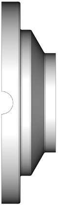
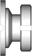
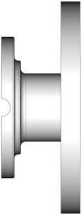
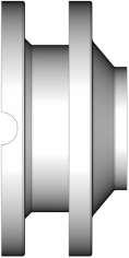
21 KIESELMANN GmbH Operating instruction Drawings and dimensions 9 9 Drawings and dimensions 9.1 Butterfly valve Drawings 1a = Housing flange with welding end 1b =Housing flange with thread end 2 = Flap 3 = Seal 4 = Screws 5 = Nuts (Illustration: G-S, without drive system) K1 = Cap K2 = Cap K3 = Cap Butterfly_valves_EN 21 / 35
 ø13x1,5 ø62 ø76 - - 24 41 - - - 78 232 Rd28x1/8 15 (ø16) ø19x1,5 ø62 ø76 ø34-24 34 41 34-78 232 Rd34x1/8 20 (ø20)")
 ø41x1,5 ø92 ø104 ø50,5 ø150 27 34 53 34 60 101 291 Rd65x1/6 50 (ø50)")
 ø104x2 ø166 ø104 ø119 ø220 34 44 78 44 77 139 329 Rd130x1/4 125")
 ø25,4x1,65 ø80 ø104 ø50,5-27 34 49 34-95 285 Rd52x1/6 1½ (ø34,8) ø38,1x1,65 ø92 ø104 ø50,5-27 34 53 34-101 291 Rd65x1/6 2")
 ø76.2x1.65 ø146 ø104 ø91-36 44 73 44-129 319 Rd104x1/6 4 (ø97,4) ø101.6x2.")
22 9 Drawings and dimensions Operating instruction Betriebsanleitung Dimensions S G K/M Cl Fl DN / OD d1 d2 d3 d4 d5 L1 L2 L3 L4 L5 H1 H2 Rd 10 (ø10) ø13x1,5 ø62 ø Rd28x1/8 15 (ø16) ø19x1,5 ø62 ø76 ø Rd34x1/8 20 (ø20) ø23x1,5 ø72 ø76 ø Rd44x1/6 25 (ø26) ø29x1,5 ø80 ø104 ø50,5 ø Rd52x1/6 32 (ø32) ø35x1,5 ø86 ø104 ø50,5 ø Rd58x1/6 40 (ø38) ø41x1,5 ø92 ø104 ø50,5 ø Rd65x1/6 50 (ø50) ø53x1,5 ø108 ø104 ø64 ø Rd78x1/6 65 (ø66) ø70x2 ø130 ø104 ø91 ø Rd95x1/6 80 (ø81) ø85x2 ø146 ø104 ø106 ø Rd110x1/4 100 (ø100) ø104x2 ø166 ø104 ø119 ø Rd130x1/4 125 (ø125) ø129x2 ø205 ø129 - ø Rd160x1/4 150 (ø150) ø154x2 ø240 ø129 - ø Rd190x1/4 1 (ø22,1) ø25,4x1,65 ø80 ø104 ø50, Rd52x1/6 1½ (ø34,8) ø38,1x1,65 ø92 ø104 ø50, Rd65x1/6 2 (ø47,5) ø50,8x1,65 ø108 ø104 ø Rd78x1/6 2½ (ø60,2) ø63,5x1,65 ø130 ø104 ø77, Rd95x1/6 3 (ø72,9) ø76.2x1.65 ø146 ø104 ø Rd104x1/6 4 (ø97,4) ø101.6x2.11 ø166 ø104 ø Rd130x1/4 22 / 35 Butterfly_valves_EN

 Cap K2) cap")
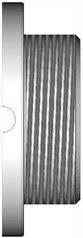
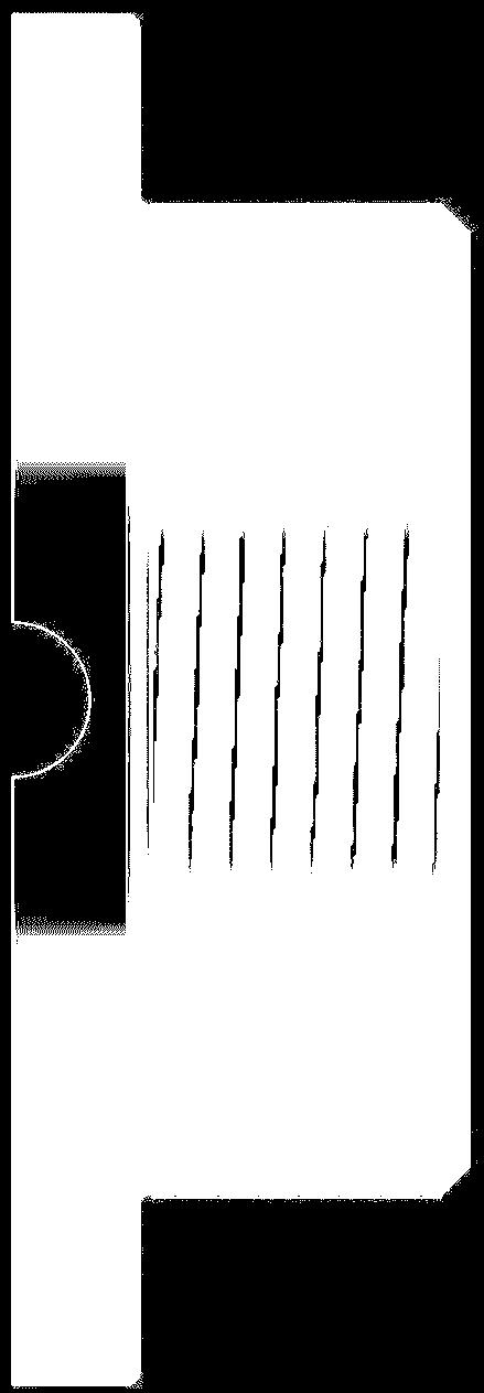
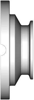
23 KIESELMANN GmbH Operating instruction Drawings and dimensions Intermediate flange-butterfly valves Drawings Intermediate flange-butterfly valve DN15 - DN150 / 1Inch - 4Inch 1= Housing flange 2= Flap 3= Seal 4= Screws 5= Nut 6= Discs 7= Screws 8= Flanges 9= Seals K1) Cap K2) cap Butterfly_valves_EN 23 / 35
 = Backup ring upper")

24 9 Drawings and dimensions Operating instruction Betriebsanleitung Drawing Intermediate flange-butterfly valve DN200 1 = Housing flanges 2 = Flap 3 = Seal 3a) = Backup ring upper 3b) = Backup ring lower 4 = Screws 5 = Nuts 6 = Plain bearing 7 = Screws 8 = Flange 9 = Seals 10 = Discs 11 = Scraper ring H = Hand lever H1 = Screw H2 = Locking disc 24 / 35 Butterfly_valves_EN
 ø35x1,5 ø86 ø104 51 27 98 288 40 (ø38) ø41x1,5 ø92 ø104 51 27 101 291 50 (ø50) ø53x1,5 ø108 ø104 53 29 109 300 65 (ø66) ø70x2 ø130 ø104 54 30 121 311 80 (ø81) ø85x2 ø146")
25 KIESELMANN GmbH Operating instruction Drawings and dimensions 9 Dimensions DN/OD d1 d2 d3 L1 L2 H1 H2 15 (ø16) ø19x1,5 ø62 ø (ø20) ø23x1,5 ø72 ø (ø26) ø29x1,5 ø80 ø (ø32) ø35x1,5 ø86 ø (ø38) ø41x1,5 ø92 ø (ø50) ø53x1,5 ø108 ø (ø66) ø70x2 ø130 ø (ø81) ø85x2 ø146 ø (ø100) ø104x2 ø166 ø (ø125) ø129x2 ø205 ø (ø150) ø154x2 ø240 ø (ø200) ø204x2 ø334 ø (ø22,1) ø25,4x1,65 ø ½ (ø34,8) ø38,1x1,65 ø82 ø (ø47,5) ø50,8x1,65 ø108 ø ½ (ø60,2) ø63,5x1,65 ø130 ø (ø72,9) ø76.2x1.65 ø146 ø (ø97,4) ø101.6x2.11 ø166 ø Butterfly_valves_EN 25 / 35
 1a = upper housing part 1b")
 d) Liner / nut - connection 9 = Plain bearing 10 = Straight pins A = Actuator A1 = Square boss A2 = Angle bracket A3 = Screws A4 = Screws H = Hand lever H1 =")
26 9 Drawings and dimensions Operating instruction Betriebsanleitung 9.3 Leakage butterfly valve Drawings Leakage butterfly valves DN 15 - DN 125 / OD 1inch - OD 4inch (Illustration basic vlave Type: LSV 4365 DN65) 1a = upper housing part 1b =lower housing part 2 = Flap 3 = Seal 4 = Screws 5 = Nuts 6 = Discs 7 = Screws 8 = Flange with ) a) Welding connection (2069) ) b) Welding connection (2041) ) c) Male connection ) d) Liner / nut - connection 9 = Plain bearing 10 = Straight pins A = Actuator A1 = Square boss A2 = Angle bracket A3 = Screws A4 = Screws H = Hand lever H1 = Saucer-head screw H2 = Locking disc H3 = Screws L = Leakage drain LA = air supply 26 / 35 Butterfly_valves_EN
27 KIESELMANN GmbH Operating instruction Drawings and dimensions 9 Dimensions Basic Type: 4366 Type: 4766 Type: 4866 S - S Type: 4367 Type: 4767 Type: 4867 G - S Type: 4368 Type: 4768 Type: 4868 G - G Type: 4369 Type: 4769 Type: 4869 K/M - G Type: 4370 Type: 4770 Type: 4870 DN / OD d1 d2 d3 L1 L2 L3 L4 L5 L6 L7 H1 H2 H3 H4 Rd1/Rd2 50 (ø50) ø53x1,5 ø110 ø Rd78x1/6 65 (ø66) ø70x2 ø130 ø Rd95x1/6 80 (ø81) ø85x2 ø145 ø Rd110x1/4 100 (ø100) ø104x2 ø165 ø Rd130x1/4 125 (ø125) ø129x2 ø195 ø Rd160x1/4 2 (ø47,5) ø50,8x1,65 ø110 ø Rd78x1/6 2½ (ø60,2) ø63,5x1,65 ø130 ø Rd95x1/6 3 (ø72,9) ø76.2x1.65 ø145 ø Rd104x1/6 4 (ø97,4) ø101.6x2.11 ø165 ø Rd130x1/4 Drawing Leakage - butterfly valves DN150 Butterfly_valves_EN 27 / 35

 ø154x2 ø240 ø129 285 68 199 406 510 155 28 / 35")
28 9 Drawings and dimensions Operating instruction Betriebsanleitung 1 = Housing flange 2 = Flap 3 = Seal 4 = Screws 5 = Nuts 6 = Discs 7 = Screws 8 = Welding flange 9 = Plain bearing 10 = O-rings 11 = Plain bearing 12 = Seal 13 = Cap 14 = Screw 15 = Seal 16 = Disc A = Actuator A1 = Square boss A2 = Angle bracket A3 = Screws Dimension H = Hand lever H1 = Screw H2 = Locking disc L = Leakage drain LA = air supply DN / OD d1 d2 d3 L1 L2 H1 H2 H3 H4 150 (ø150) ø154x2 ø240 ø / 35 Butterfly_valves_EN

 Screws A2) Square boss A3) Angle")


29 KIESELMANN GmbH Operating instruction Drawings and dimensions drive systems Multiturn actuator (PDA) A) Actuator PDA 75 PDA 100 PDA 125 A1) Screws A2) Square boss A3) Angle bracket A4) Screws A5) Nuts R) Position indication with sensor mounting test DN L s s Hand lever Standard Model DN L s hand lever Standard Type 4335 L s Hand lever Standard - with sensor mounting Type 4321 L Butterfly_valves_EN 29 / 35


30 9 Drawings and dimensions Operating instruction Betriebsanleitung Hand lever with continuously adjustable Model DN L s Hand lever continuously adjustable Type 4600 s L Hand lever - stainless steel Model DN L s Hand lever - stainless steel Type 4318 s L Hand lever - stainless steel with sensor mounting Type 4321 L / 35 Butterfly_valves_EN
31 KIESELMANN GmbH Operating instruction Wearing parts Wearing parts 10.1 Butterfly valve Seal (3) DN SILICONE EPDM HNBR FKM ½ ½ Leakage - butterfly valves Seal (3) Plain bearing (9) Gleitlager (11) Seal (L1) DN SILICONE EPDM HNBR iglidur EPDM ½ Butterfly_valves_EN 31 / 35
32 10 Wearing parts Operating instruction Betriebsanleitung 10.3 Intermediate - butterfly valve Seal (3) Seal (9) DN SILICONE EPDM HNBR FKM k -flex ½ ½ Malfunctions Malfunction Cause Remedy Valve does not move Signals do not come on Valve moves too slowly Valve moves unevenly Valve causes excessive mechanical noises - Compressed air missing - Electrical controller missing - Actuator defective - Loose cable on pilot valve or initiator - Cable broken - Initiators defective - Pilot valve defective - Electrical supply missing or damaged - Compressed air too low - Exhaust hole actuator plugged up - Compressed air supply too weak - Media pressure too high - Electric signals uneven - Switch on compressed air - Check and ensure electrical signals - Check and ensure electrical signals - Tighten cable - Replace cable - Replace initiators - Replace pilot valve - Check or remedy - Increase compressed air - Clear opening - Increase compressed air - Check media pressure and adjust if necessary - Remedy signal flow malfunction - Lubrication missing - Lubricate seal and guide elements 32 / 35 Butterfly_valves_EN
33 KIESELMANN GmbH Operating instruction Classification Classification 11.1 Structure of order number X X X X X X X X X - X X X X - Control system and position indication - External surface Separator - Material of seals Valve size DN / OD Connection variants Product type/din/inch 0-2 Product type XXxx xxx xxx-xxxx Designation 4 3 x x Butterfly valve/leakage butterfly valve manual operating 4 5 x x Butterfly valve/leakage butterfly valve pneumatic operating air open- spring close (NC) 4 4 x x Butterfly valve/leakage butterfly valve pneumatic operating air open - air close (DA) 2-3 Connection variant xxxx xxx xxx-xxxx z.b. Type 4502 = Male flange / Welding flange oder Type 4510 = Intermediate (see Valve types [} 10]) 4-6 Valve size DN/OD xxxx XXX xxx-xxxx DN OD DN OD 1" DN OD 1 1/2" DN OD 2 " DN OD 2 1/2" DN OD 3 " DN OD 4 " DN DN DN Butterfly_valves_EN 33 / 35
34 11 Classification Operating instruction Betriebsanleitung 7-9 Material of seals xxxx xxx XXX-xxxx Sealing material - in product contact EPDM HNBR Silicone FKM Separator xxxx xxx xxx - xxxx Control system and position indication, External surface xxxx xxx xxx - xxxx Control system and position indicator Valve with position indication external surface AISI304 blanc Valve with position indication external surface AISI304 e-polished Valve with position indication external surface AISI304 mat finish Valve with position indication external surface AISI316L blanc Valve with position indication external surface AISI316L e-polished Valve with position indication external surface AISI316L mat finish Valve with control head KI-Top SPS K 5 X X Valve with control head KI-Top ASI-Bus K 6 X X 34 / 35 Butterfly_valves_EN
35 KIESELMANN GmbH Operating instruction Appendix Appendix 12.1 Declaration of incorporation Butterfly_valves_EN 35 / 35
Operating instruction
 Translation of the original Operating instruction Butterfly valve P D F a k 1 6 / 0 2 / 2 0 1 8 ENGLISH EN K I E S E L M A N N G m b H Paul-Kieselmann-Str. 4-10 75438 Knittlingen ( +49(0) 7043 371-0 7
Operating Instruction:
 Operating Instruction: Leakage - Butterfly valve with manual operation Types LSV 4365 LSV 4366 LSV 4367 LSV 4368 LSV 4369 LSV 4370 Kieselmann GmbH Paul-Kieselmann-Str. 4-10 75438 Knittlingen Telefon +49
Operating instructions - Translation of the original -
 Operating instructions - Translation of the original - KIESELMANN GmbH Paul-Kieselmann-Str.4-10 D - 75438 Knittlingen +49 (0) 7043 371-0 Fax: +49 (0) 7043 371-125 www.kieselmann.de sales@kieselmann.de
Operating instructions - Translation of the original -
 Operating instructions - Translation of the original - Ball-type check valve Type: 5080 KIESELMANN GmbH Paul-Kieselmann-Str.4-10 D - 75438 Knittlingen +49 (0) 7043 371-0 Fax: +49 (0) 7043 371-125 www.kieselmann.de
Operating instructions - Translation of the original -
 Operating instructions - Translation of the original - Single seat valve pneumatic operation KIESELMANN GmbH Paul-Kieselmann-Str.4-10 D - 75438 Knittlingen +49 (0) 7043 371-0 Fax: +49 (0) 7043 371-125
Operating instructions - Translation of the original -
 Operating instructions - Translation of the original - Single seat valve Two-way-valve Type: 5714 pneumatic operation KIESELMANN GmbH Paul-Kieselmann-Str.4-10 D - 75438 Knittlingen +49 (0) 7043 371-0 Fax:
Operating instructions - Translation of the original -
 Operating instructions - Translation of the original - Flow control valve Type: 57xx KIESELMNN GmbH Paul-Kieselmann-Str.4-10 D - 75438 Knittlingen +49 (0) 7043 371-0 Fax: +49 (0) 7043 371-125 www.kieselmann.de
Instruction Manual. Alfa Laval Safety Valve ESE03058-EN Original manual
 Instruction Manual Alfa Laval Safety Valve 2001-0000 ESE03058-EN1 2015-11 Original manual Table of contents The information herein is correct at the time of issue but may be subject to change without
Instruction Manual. Alfa Laval Safety Valve ESE03058-EN Original manual
 Instruction Manual Alfa Laval Safety Valve 2001-0000 ESE03058-EN3 2016-08 Original manual Table of contents The information herein is correct at the time of issue but may be subject to change without
DSV. Operating Manual. Double Seal Butterfly Valve. Read and understand this manual prior to operating or servicing this product.
 Operating Manual DSV Double Seal Butterfly Valve Read and understand this manual prior to operating or servicing this product. www.sks-online.com UK DSV-UK2.qxp / 10.2005 Table of Contents: Page: 1.
Butterfly valves Leakage butterfly valves Ball valves
 SO EVERYTHING KEEPS FLOWING Butterfly valves Leakage butterfly valves Ball valves Quality down to the smallest detail Butterfly valves and ball valves are the most used shutoff devices in process engineering.
Butterfly valves Leakage butterfly valves Ball valves. Standard
 Butterfly valves Leakage butterfly valves Ball valves Standard High standard with the option of security against leakage Quality down to the smallest detail Butterfly valves and ball valves are the most
DELTA PR2. Operating Manual. Sampling Valve. Read and understand this manual prior to operating or servicing this product.
 Operating Manual DELTA PR2 Sampling Valve Read and understand this manual prior to operating or servicing this product. UK Declaration of Conformity for Valves and Valve Manifolds SPX Flow Technology
Butterfly valves Leakage butterfly valves
 Butterfly valves Leakage butterfly valves www.rodgerindustries.com RODGER INDUSTRIES INC. Size D1 D5 L1 L2 L3 Weight (kg) (Metric millimeters) 1" 22.9 50.5 68 34 95 1,21 1.5" 35.1 50.5 68 34 101 1.29 2"
Operating Instructions
 Operating Instructions ASI Control Head for Lift and Turning Valves Subject to technical modifications and innovations. Rev. 6 ASI Steuerkopf für Hub- und Drehventile Beschreibung 100xxx / Doku / Elek
Operating Instructions Garlock Butterfly Valves DN : mm / 2-24
 Operating Instructions Garlock Butterfly Valves DN : 50-600 mm / 2-24 PN : 10 / 16 Type: GAR-SEAL SAFETY-SEAL STERILE-SEAL MOBILE-SEAL Conformity declaration... 14 0 Introduction... 15 1 Proper use...
T-smart Butterfly Valves. Made by GEA Tuchenhagen. GEA Mechanical Equipment / GEA Tuchenhagen
 Liquids to Value T-smart Butterfly Valves Made by GEA Mechanical Equipment / T-smart Butterfly Valves For many years, butterfly valves have proven their worth in process plants with different types of
Double Seat Valves Double Seat Blanking Plugs. Hygiene
 Double Seat Valves Double Seat Blanking Plugs Hygiene Double Seat Valves Divided Valve Disks for Maximum Security KIESELMANN double seat valves are leak-proof valves and serve to separate incompatible
Mounting and Operating Instructions EB 8222 EN. Type 3310/AT and Type 3310/3278 Pneumatic Control Valves. Type 3310 Segmented Ball Valve
 Type 3310/AT and Type 3310/3278 Pneumatic Control Valves Type 3310 Segmented Ball Valve Fig. 1 Type 3310/3278 with positioner Fig. 2 Type 3310/AT Mounting and Operating Instructions EB 8222 EN Edition
Operating Instructions
 Operating Instructions ASI Control Head for Lift and Turning Valves Subject to technical modifications and innovations. Rev. 4 ASI Steuerkopf für Hub- und Drehventile Beschreibung 100xxx / Doku / Elek
Mounting and Operating Instructions EB 8097 EN. Pneumatic Control Valves Type and Type
 Pneumatic Control Valves Type 3347-1 and Type 3347-7 Hollow-mold cast body with welding ends Full-mold cast body with threaded connections Fig. 1 Type 3347-7 Control Valve with Type 3277 Actuator and integral
Mounting and Operating Instructions EB 8048 EN. Type and Type Pneumatic Control Valves Type 3249 Aseptic Angle Valve
 Type 3249-1 and Type 3249-7 Pneumatic Control Valves Type 3249 Aseptic Angle Valve Ball body version Special version with packing Type 3249-7 Control Valve with Type 3277 Actuator and integrated positioner
Mounting and Operating Instructions EB 8097 EN. Type and Type Pneumatic Control Valves
 Type 3347-1 and Type 3347-7 Pneumatic Control Valves Type 3347-7, cast body with welding ends Type 3347-7, bar stock body with threaded connections Mounting and Operating Instructions EB 8097 EN Edition
Valve Technology DIN EN Butterfly Valves
 Armaturenwerk Hötensleben GmbH Valve Technology DIN EN 14432 Butterfly Valves A member of NEUMO Ehrenberg Group Edition 3.0 Proven Valves for all Purpose ATEX Directive 2014/34/EU Armaturenwerk Hötensleben
Unique 7000 Series Valve - Standard and Reverse Acting
 Instruction Manual Unique 7000 Series Valve - Standard and Reverse Acting ESE00213-ENUS4 2012-01 Original manual Table of contents The information herein is correct at the time of issue but may be subject
Installation and Operating Instructions
 Original Installation and Operating Instructions Hawle E2 Valve with Flange Outlet, System 2000 or PE Spigot Ends Table of Contents A) General...... 2 A1 Symbols..... 2 A2 Intended use... 2 A3 Labeling...
Mounting and Operating Instructions EB 8135/8136 EN. Series V2001 Valves Type 3535 Three-way Valve for Heat Transfer Oil
 Series V2001 Valves Type 3535 Three-way Valve for Heat Transfer Oil Type 3535 Three-way Valve with bellows seal and rod-type yoke (partial view) Mounting and Operating Instructions EB 8135/8136 EN Edition
Angle seat valve with diaphragm actuator VZXA-...-M
 Angle seat valve with diaphragm actuator VZXA-...-M Instructions Operating (Translation of the original instructions) Festo AG & Co. KG Ruiter Straße 82 73734 Esslingen Germany +49 711 347-0 www.festo.com
Angle seat valve with piston actuator VZXA-...-K
 Angle seat valve with piston actuator VZXA-...-K Festo AG & Co. KG Postfach 73726 Esslingen Germany +49 711 347-0 www.festo.com 3 Further information Accessories www.festo.com/catalogue Spare parts www.festo.com/spareparts
HST -LS Interlocking device (Translation of Original Manual)
") Installation and Operating Manual for Components HST -LS Interlocking device (Translation of Original Manual) HST-LS Ident.-No.: 10268 HST-LS Ident.-No.: 10269 HST-LS, pictured Ident-Nr. 10269 The image
Installation and Operating Manual for Components HST -LS Interlocking device (Translation of Original Manual) HST-LS Ident.-No.: 10268 HST-LS Ident.-No.: 10269 HST-LS, pictured Ident-Nr. 10269 The image
Type Operating Instructions. Bedienungsanleitung Manuel d utilisation. 2/2-way solenoid valve 2/2-Wege-Magnetventil Électrovanne 2/2 voies
 Type 5404 2/2-way solenoid valve 2/2-Wege-Magnetventil Électrovanne 2/2 voies Operating Instructions Bedienungsanleitung Manuel d utilisation Contents 1 Operating instructions...2 2 Intended use...3 3
Installation, Operation, and Maintenance Manual
 Industrial Process Installation, Operation, and Maintenance Manual Series PBV Plastic Lined Ball Valve Table of Contents Table of Contents Introduction and Safety...2 Safety message levels...2 User health
Operating Instructions
 Armaturen GmbH Armaturen, Rohre, Sonderteile aus Edelstahl fittings, pipes, special parts of stainless steel Operating Instructions Safety valve spring loaded TYPE FSV2000 M & S Armaturen GmbH Industriestraße
Storage, operating and maintenance instructions for AZ plug valves and Standard valves
 ARMATUREN Plug - Valves metallic with PTFE Sleeve 2-7 way Storage, operating and maintenance instructions for AZ plug valves and Standard valves Plug - Valves FEP/PFA - lined, 2-3 way Butterfly - Valves
Installation, Operation, and Maintenance Manual
 Industrial Process Installation, Operation, and Maintenance Manual Series PBFV Plastic Lined Butterfly Valve - Lug and Wafer Style Table of Contents Table of Contents Introduction and Safety...2 Safety
Drive Unit e-drive1. Installation instructions 04/2014. English translation of the original German installation instructions
 Drive Unit e-drive1 Installation instructions 04/2014 English translation of the original German installation instructions Contents Foreword... 3 Availability... 3 Structural features in the text... 3
back to main page Type: Butterfly valves Instructions and Operation Manual Warning! Warning! Danger for life! 1. Intended use Danger for life!
 Instructions and operation manual for butterfly valves This manual is intended to support the users of Herberholz butterfly valves type HRD/HRA, RD/RA, LDKE/LDKF for installation, operation and maintenance
Rotary feed-through DDF-S/-KS
 Translation of the Original Operating Manual Rotary feed-through DDF-S/-KS Assembly and Operating Manual Superior Clamping and Gripping Imprint Imprint Copyright: This manual remains the copyrighted property
Membranventil Kunststoff, DN Diaphragm Valve Plastic, DN GEMÜ 600 Antriebsgröße Code 2-4 Actuator size Code 2-4
 Membranventil Kunststoff, DN - 50 Diaphragm Valve Plastic, DN - 50 DE GB ORIGINAL EINBAU- UND MONTAGEANLEITUNG INSTALLATION, OPERATING AND MAINTENANCE INSTRUCTIONS GEMÜ 600 Antriebsgröße Code -4 Actuator
Operating Instructions
 Armaturen GmbH Armaturen, Rohre, Sonderteile aus Edelstahl fittings, pipes, special parts of stainless steel Operating Instructions BaseCom butterfly valve Rev.0 / 12.12.2009 Page 1 of 8 BA52290GB.doc
Type 2000, Operating Instructions. Bedienungsanleitung Manuel d utilisation
 2/2 way angle seat valve, 3/2 way globe valve 2/2-Wege-Schrägsitzventil, 3/2-Wege-Geradsitzventil Vanne à siège incliné 2/2 voies, vanne à siège droit 3/2 voies Operating Instructions Bedienungsanleitung
Mounting and Operating Instructions EB 5863 EN. Electric Control Valves. Pneumatic Control Valve
 Electric Control Valves Types 3226/5857, 3226/5824, 3226/5825, 3226/5757-7, 3226/5724-8, 3226/5725-7, 3226/5725-8 Pneumatic Control Valve Type 3226/2780 Type 3226/5857 Type 3226/5757-7 Type 3226/2780-2,
NAF-Torex butterfly valves Maintenance and installation instructions List of spare parts
 NAF-Torex butterfly valves Maintenance and installation instructions List of spare parts Fi 41.42(4)GB 08.01 Contents SAFETY General 1 Lifting 2 Receiving inspection 3 Installation 4 Flange gaskets 5 Starting
Angle seat valve with piston actuator VZXA-...-K
 Angle seat valve with piston actuator VZXA-...-K Instructions Operating (Translation of the original instructions) Festo AG & Co. KG Ruiter Straße 82 73734 Esslingen Germany +49 711 347-0 www.festo.com
KEYSTONE. Hygienic butterfly valves model F250 & F251 Installation & Maintenance Instructions. 1 Contents 1 Contents 1
 Installation & Maintenance Instructions KEYSTONE 1 Contents 1 Contents 1 2 Introduction 1 2.1 Valve use 1 2.2. Application area 1 2.3. Incorrect use 1 3. Safety 2 4. Transport and storage 2 5. Installation
Armaturenwerk Hötensleben GmbH. Valve Technology. A member of NEUMO Ehrenberg Group. Edition 3.0
 Armaturenwerk Hötensleben GmbH Valve Technology A member of NEUMO Ehrenberg Group Edition 3.0 Proven Valves for all Purpose ATEX Directive 2014/34/EU Armaturenwerk Hötensleben GmbH is using the revised
Mounting and Operating Instructions EB 8053 EN. Series 250 Type and Type Pneumatic Control Valves
 Series 250 Type 3252 1 and Type 3252 7 Pneumatic Control Valves Type 3252 High-pressure valve with Type 3277 Pneumatic Actuator and Type 3767 Electropneumatic Positioner Mounting and Operating Instructions
Operating Instruction
 Armaturen GmbH Armaturen, Rohre, Sonderteile aus Edelstahl fittings, pipes, special parts of stainless steel Operating Instruction Leakage butterfly valve manually operated with handle LSV07 manually operated
Swiveling gripper finger GFS 16-40
 Translation of the original manual Swiveling gripper finger GFS 16-40 Assembly and Operating Manual Superior Clamping and Gripping Imprint Imprint Copyright: This manual remains the copyrighted property
Type Operating Instructions. Bedienungsanleitung Manuel d utilisation. 2/2-Way Solenoid Valve 2/2-Wege-Magnetventil Électrovanne à 2/2 voies
 Type 5282 2/2-Way Solenoid Valve 2/2-Wege-Magnetventil Électrovanne à 2/2 voies Operating Instructions Bedienungsanleitung Manuel d utilisation Contents 1 Operating Instructions... 2 2 Authorized use...
Type Operating Instructions. Bedienungsanleitung Manuel d utilisation. 2/2-Way Solenoid Valve 2/2-Wege-Magnetventil Électrovanne à 2/2 voies
 Type 5282 2/2-Way Solenoid Valve 2/2-Wege-Magnetventil Électrovanne à 2/2 voies Operating Instructions Bedienungsanleitung Manuel d utilisation 1 OPERATING INSTRUCTIONS The operating instructions contain
Type 0283, Operating Instructions. Bedienungsanleitung Manuel d utilisation. 2/2-way solenoid valve 2/2-Wege-Magnetventil Électrovanne 2/2 voies
 Type 0283, 0293 2/2-way solenoid valve 2/2-Wege-Magnetventil Électrovanne 2/2 voies Operating Instructions Bedienungsanleitung Manuel d utilisation Contents 1 The operating instructions...2 2 Intended
Instruction Manual. Unique Single Seat Valve - Manually Operated ESE00523-EN Original manual TD TD
 Instruction Manual Unique Single Seat Valve - Manually Operated TD 461-583 TD 461-791 ESE00523-EN2 2010-02 Original manual Table of contents The information herein is correct at the time of issue but
Mounting and Operating Instructions EB 8227 EN. Pneumatic Control Valve Type 3331/BR 31a Special version Type 3331/3278. Type 3331 Butterfly Valve
 Pneumatic Control Valve Type 3331/BR 31a Special version Type 3331/3278 Type 3331 Butterfly Valve Fig. 1 Type 3331/BR 31a (below) and Type 3331/3278 (top) Mounting and Operating Instructions EB 8227 EN
Operating manual Separator
 Operating manual Separator Sheet no. AS/4.1.141.1.1 issue 20.08.2014 Contents Section Title Page 0 Introduction... 1 1 Intended use......1 2 Marking of the fitting... 1 3 Safety instructions... 2 4 Transport
Safety. Operating instructions Solenoid valve VGP DANGER. Contents WARNING CAUTION. Changes to edition Elster GmbH Edition 10.
 27 Elster GmbH Edition.7 Translation from the German 344297 D F NL I E DK S N P GR TR CZ PL RUS H www.docuthek.com Operating instructions Solenoid valve Contents Solenoid valve... Contents... Safety....
Mounting and Operating Instructions EB 8111/8112 EN. Series V2001 Valves Type 3321 Globe Valve
 Series V2001 Valves Type 3321 Globe Valve Type 3321 Globe Valve with rod-type yoke and Type 3372 Electropneumatic Actuator (350 cm²) Mounting and Operating Instructions EB 8111/8112 EN Edition June 2013
Product Information Overspeed governor GB 260
 Product Information GB 260 Copyright as per DIN ISO 16016. Manufactured under licence of C. Haushahn GmbH & Co. I Subject to modification. Published by SLC Sautter Lift Components GmbH & Co. KG Borsigstrasse
Butterfly Valve Type 57P
 Butterfly Valve Type 57P Contents Lever Type: 50-200 mm (2-8 ) Body Material: CPVC Gear Type: 50-200mm (2-8 ) Body Material: CPVC (1) Be sure to read the following warranty clauses of our product 1 (2)
Mounting and Operating Instructions EB 8039 EN. Type 3351 Pneumatic On/off Valve. Type 3351 Pneumatic On/off Valve. Type 3351 Pneumatic On/off Valve
 Type 3351 Pneumatic On/off Valve Type 3351 Pneumatic On/off Valve Type 3351 Pneumatic On/off Valve Version with handwheel Mounting and Operating Instructions EB 8039 EN Edition May 2016 Definition of signal
series BUTTERFLY VALVE DOUBLE ECCENTRIC FLANGED FAF 3800 PRODUCTION STANDARDS DN100 DN2000 PN Design EN 593 EN ISO Flanged
 PRODUCTION STANDARDS DN100 DN2000 PN 10-16-25 Design EN 593 Connection End Connection EN 1092-2 ISO 7005-2 - Flanged EN 558 Series 14 DIN 3202 F4 Marking EN 19 Tests EN 12266-1 Corrosion Protection Electrostatic
Instruction Manual. Automatic Fuel Oil De-aerator Flow-Control. Flow-Control 3/K-1 # Flow-Control 3/K-2 # 70019
 Mess-, Regel- und Überwachungsgeräte für Haustechnik, Industrie und Umweltschutz Lindenstraße 20 DE-74363 Güglingen Telefon: +49(0)7135-102-0 Service: +49(0)7135-102-211 Telefax: +49(0)7135-102-147 E-Mail:
DELTA RUF3. Operating Manual. Non - return Valve. Read and understand this manual prior to operating or servicing this product.
 Operating Manual DELTA RUF3 Non - return Valve Read and understand this manual prior to operating or servicing this product. www.sks-online.com UK Table of contents Page 1. General Terms 2 2. Safety
Globe Valve Type Fig. 1 Type 3241 Globe Valve. Mounting and Operating Instructions EB EN
 Globe Valve Type 3241 Fig. 1 Type 3241 Globe Valve Mounting and Operating Instructions EB 8015-1 EN Edition July 2012 Contents Contents Page 1 Design and principle of operation.................... 4 2
Type 3571 Pneumatic Actuator. Actuator areas: 27 in² 54 in² 116 in². Original instructions. Mounting and Operating Instructions EB 8820 EN
 Type 3571 Pneumatic Actuator Actuator areas: 27 in² 54 in² 116 in² Original instructions Mounting and Operating Instructions Edition April 2016 Note on these mounting and operating instructions These mounting
CATALOG. Actuated Diaphragm Valve DN PVC-U / PVC-C / PP-H / PVDF / ABS SMART IN FLOW CONTROL.
 CATALOG Actuated Diaphragm Valve DN 15-100 PVC-U / PVC-C / PP-H / PVDF / ABS SMART IN FLOW CONTROL. TABLE OF CONTENTS Type 186 - DN 12-15 (MA 10) 04 General information - Technical specification 04 Sectional
PNEUMATICALLY ACTUATED 2-WAY
 482 DN 25-65 The 482 diaphragm valve is particularly suitable for shutting off and regulating abrasive or dirty fluids. The new internal geometry of the body optimises fluid dynamic efficiency by increasing
General operating manual for assembly, commissioning and maintenance of valves and hydraulic manifolds
 for assembly, commissioning and maintenance of valves and hydraulic manifolds 110210_general_operating_manual 07.2018 Table of contents Contents Page Important information 2 Important safety instructions
Mounting and Operating Instructions EB 8111/8112 EN. Valve Series V2001 Globe Valve Type 3321
 Valve Series V2001 Globe Valve Type 3321 Fig. 1 Type 3321 Valve with mounted rod-type yoke for pneumatic or electric actuators (partial view) Mounting and Operating Instructions EB 8111/8112 EN Edition
Safety. Operating instructions Solenoid valve for gas VG 6 VG 15/10 DANGER. Contents WARNING CAUTION. Changes to edition 07.15
 17 Elster GmbH Edition 1.17 Translation from the German 519 D F NL I E DK S N P GR TR CZ PL RUS H www.docuthek.com Operating instructions Solenoid valve for gas VG VG 15/1 Contents Solenoid valve for gas
Type 6213 EV, 6281 EV
 Type 6213 EV, 6281 EV 2/2-way solenoid valve 2/2-Wege-Magnetventil Électrovanne 2/2 voies Operating Instructions Bedienungsanleitung Manuel d utilisation 1 OPERATING INSTRUCTIONS The operating instructions
DELTA DKRH2. Operating Manual. -High Pressure Designwww.sks-online.com. Double Seat Ball Valve with Cleaning Connection
 Operating Manual DELTA DKRH2 Read and understand this manual prior to operating or servicing this product. Double Seat Ball Valve with Cleaning Connection - Declaration of Conformity for Valves and Valve
Operating Instructions
 Operating Instructions Quadax Series Butterfly Valves (with actuator) Version September 2009 müller co-ax ag Gottfried-Müller-Str. 1 74670 Forchtenberg Germany Tel. +49 7947 828-0 Fax +49 7947 828-11 E-Mail
2/2-way Diaphragm Valve with stainless steel design, weld end or clamp connection, DN 8-25
 2/2-way Diaphragm Valve with stainless steel design, weld end or clamp connection, DN 8-25 Type 2103 can be combined with Hermetical separation of fl uids from the operating mechanism by diaphragm Zero
BAA S370 Select. SVP valve (Right angle, double right angle, cross, angular seat variant) DN , DN 1 4
 DN , DN 1 4") BAA S370 Select SVP valve (Right angle, double right angle, cross, angular seat variant) Manually and pneum. operated Änderung Datum Name Änderung Datum Name Änderung Datum Name Änderung Datum Name erst.
BAA S370 Select SVP valve (Right angle, double right angle, cross, angular seat variant) Manually and pneum. operated Änderung Datum Name Änderung Datum Name Änderung Datum Name Änderung Datum Name erst.
Operating and maintenance manual Multi-spring actuator ARCAPAQ Series / 1.0
 Operating and maintenance manual Multi-spring actuator ARCAPAQ Series 812 03.2016 / 1.0 Original instructions ARCA Regler GmbH. All rights reserved. Cover picture background: Freepik.com ARCA Regler GmbH
Instruction Manual. Unique Single Seat Valve - Long Stroke ESE00222-EN
 Instruction Manual Unique Single Seat Valve - Long Stroke ESE00222-EN4 2014-12 Original manual Table of contents The information herein is correct at the time of issue but may be subject to change without
485 - NC NO/DA DN
 485 - NC 285 - NO/DA DN 25-100 The 485/285 diaphragm valve is particularly suitable for shutting off and regulating abrasive or dirty fluids. The new internal geometry of the body optimises fluid dynamic
Diaphragm Valve, Metal
 Diaphragm Valve, Metal Construction The GEMÜ pneumatically operated 2/2-way diaphragm valve has a low maintenance actuator. Normally Closed, Normally Open and Double Acting control functions are available.
Instruction Manual. Unique Single Seat Valve - Tank Outlet ESE00364-EN Original manual TD _2
 Instruction Manual Unique Single Seat Valve - Tank Outlet TD 461-494_2 ESE00364-EN5 2011-05 Original manual Table of contents The information herein is correct at the time of issue but may be subject
Pneumatic operated 2/2-way Diaphragm Valve
 Pneumatic operated 2/2-way Valve Light tube valve body Flow optimised body in stainless steel Zero dead volume Easy to weld Type can be combined with... Type 8640/8644 Type 6012/6014 P Type 8311 Electrical
Quick-Disconnect Coupling one-hand operation Push Pull ND 5, connecting thread G 1/4,max. operating pressure 500 bar
 Issue 12-2013 Quick-Disconnect Coupling one-hand operation Push Pull ND 5, connecting thread G 1/4,max. operating pressure 500 bar Figure 1: Coupling complete Figure 4: Coded coupling, complete Table of
2/2-way Diaphragm Valve, forged valve body, weld end and clamp connection, DN 8-100
 2/2-way Diaphragm Valve, forged valve body, weld end and clamp, DN 8-100 Type 2031 with weld end Type 2031 can be combined with Type 2031 with clamp Hermetical separation of fluids from the operating mechanism
Air operated Pinch Valve type VMC
 Air operated Pinch Valve type VMC Flange Internal Thread Tri-Clamp Weld-on ends Threaded spigot The flexible modular system for detachable and aseptic piping connections! The ideal solution for isolation
Pneumatic Swivel Unit SRU 20-60
 Translation of the original manual Pneumatic Swivel Unit SRU 20-60 Assembly and operation manual Superior Clamping and Gripping Imprint Imprint Copyright: This manual remains the copyrighted property of
Operating Instructions Ball Valves
 Armaturen GmbH Armaturen, Rohre, Sonderteile aus Edelstahl Fittings, pipes, special parts of stainless steel Operating Instructions KV-SS KV-ZF M & S Armaturen GmbH Carl Benz Str.2 D-75057 Kürnbach Germany
Instruction Manual. Unique RV-ST Regulating Valve ESE02127-EN Original manual
 Instruction Manual Unique RV-ST Regulating Valve 2404-0022 ESE02127-EN1 2012-06 Original manual Table of contents The information herein is correct at the time of issue but may be subject to change without
Instruction Manual. SBV Sanitary Ball Valve ESE01782-EN Original manual TD
 Instruction Manual SBV Sanitary Ball Valve TD 451-013 ESE01782-EN4 2010-09 Original manual Table of contents The information herein is correct at the time of issue but may be subject to change without
Pressure relief valve
 Pressure relief valve Operating manual Series DHV 712 Version BA-2015.10.20 EN Print-No. 300 510 TR MA DE Rev001 ASV Stübbe GmbH & Co. KG Hollwieser Straße 5 32602 Vlotho Germany Phone: +49 (0) 5733-799-0
Instruction Manual. Unique 7000 Series - Long Stroke ESE00220-ENUS Original manual
 Instruction Manual Unique 7000 Series - Long Stroke ESE00220-ENUS4 2014-12 Original manual Table of contents The information herein is correct at the time of issue but may be subject to change without
Operating Guide SBFV (PN16/25) ENGLISH Steel butterfly valve SBFV Page 2. Danfoss VI.IX.A1.02 1
 ENGLISH Steel butterfly valve SBFV Page 2. Danfoss VI.IX.A1.02 1") Operating Guide SBFV (PN16/25) ENGLISH Steel butterfly valve SBFV www.danfoss.com Page 2 Danfoss 2016.06 VI.IX.A1.02 1 Table of Contents: 1. OVERVIEW... 3 2. GENERAL... 3 2.1 Safety...3 2.2 Proper use...4
Operating Guide SBFV (PN16/25) ENGLISH Steel butterfly valve SBFV www.danfoss.com Page 2 Danfoss 2016.06 VI.IX.A1.02 1 Table of Contents: 1. OVERVIEW... 3 2. GENERAL... 3 2.1 Safety...3 2.2 Proper use...4
Type Operating Instructions. Bedienungsanleitung Manuel d utilisation
 Type 0131 2/2- or 3/2-way solenoid valve 2/2- oder 3/2-Wege-Magnetventil Électrovanne 2/2 ou 3/2 voies Operating Instructions Bedienungsanleitung Manuel d utilisation 1 OPERATING INSTRUCTIONS The operating
Butterfly Valve K 220 for application in the harsh environment of the chemical industry
 Butterfly Valve K 220 for application in the harsh environment of the chemical industry Advantage DN 20 to DN 400 liner as a element liner makes additional flange seals superfluous cost efficient and direct
BIOVENT. Hygienic Valve
 BIOVENT BIOVENT Committed to perfection in every detail Powerful valve actuator BIOVENT control valves are usually combined with pneumatic multi-spring ARCAPAQ actuator type 813. Not only is it cost effective,
Type Operating Instructions. Bedienungsanleitung Manuel d utilisation. 2/2-way solenoid valve 2/2-Wege-Magnetventil Électrovanne 2/2 voies
 Type 6027 2/2-way solenoid valve 2/2-Wege-Magnetventil Électrovanne 2/2 voies Operating Instructions Bedienungsanleitung Manuel d utilisation 1 OPERATING INSTRUCTIONS The operating instructions contain
In combination with an actuator, e.g. a SAMSON Type 3271 or Type 3277 Pneumatic Actuator
 Type 3510 Micro-flow Valve In combination with an actuator, e.g. a SAMSON Type 3271 or Type 3277 Pneumatic Actuator DIN version Translation of original instructions Type 3510-1 (left) and Type 3510-7 (right)
SMB. Assembly and operating instructions Sprinkler measuring orifice SMB/SMB-OE. Sprinkler measuring orifice
 Assembly and operating instructions /-OE Fon: +49 2065 9609-0 Fax: +49 2065 9609-22 Internet: www.kt-web.de e-mail: info@kt-web.de 2 1. General...3 1.1 Exclusion of liability...3 2. Safety...4 2.1 General
Instruction Manual. Sewage lifting station compli 300
 Instruction Manual Sewage lifting station compli 300 Safety instructions Areas of application Electrical connection Installation Servicing Technical data Appendix JUNG PUMPEN GmbH Industriestr. 4-6 33803
USER INSTRUCTIONS. Installation Operation Maintenance. Valtek Torex TX Control and shut-off valves. Butterfly Valves. Experience In Motion
 USER INSTRUCTIONS Valtek Torex TX Control and shut-off valves Butterfly Valves VLEEIM4143-02 09.10 Installation Operation Maintenance Experience In Motion Contents SAFETY General 1 Lifting 2 Receiving
BUTTERFLY VALVE WITH WELDED ENDS INSTALLATION AND MAINTENANCE MANUAL
 BUTTERFLY VALVE 31300 SERIES INSTRUCTIONS FOR INSTALLATION, USE AND MAINTENANCE 1. Overview Read these instructions carefully before starting the valve installation and start-up work. Safe keep the instructions