PULLDOZER TRANSFORMER
|
|
|
- Diana Cole
- 5 years ago
- Views:
Transcription

1 PULLDOZER TRANSFORMER XL Operator, Assembly & Parts Manual Last Updated: December 6, 2018 Bridgeview Manufacturing Inc. P.O. Box 4 Gerald, Saskatchewan, Canada S0A 1B0 Phone: Fax: bmi@sasktel.net

2 PULLDOZER TRANSFORMER Your Authorized Dealer Your Serial Number The serial number is located on the back of the middle blade on the left side of the machine. BRIDGEVIEW MANUFACTURING INC. ii
3 PULLDOZER TRANSFORMER TABLE OF CONTENTS 1 INTRODUCTION Safety Precautions Power Requirements: Transportation Storage Lights and Marking Field to Transport Position FEATURES AND OPERATION Hydraulic Systems Hitch Options Tires Lubrication Blade Options Trencher Option GPS Option ASSEMBLY & PARTS MANUAL Component Information Body Assembly Hydraulics Assembly Electrical Assembly Miscellaneous Trencher Option Decals NOTES BRIDGEVIEW MANUFACTURING INC. iii
4 1 INTRODUCTION PULLDOZER TRANSFORMER 1 INTRODUCTION Thank you for purchasing a Pulldozer Transformer from Bridgeview Manufacturing. With the proper operation and service as outlined in this manual, the Pulldozer Transformer will provide you with years of trouble free operation. This is a complete safety, operation and parts manual for the Pulldozer Transformer. The manual covers in detail how to safely and effectively use your new machine. The procedures outlined in this manual should be followed to ensure safe operation and longevity of your machine. The parts and assembly manual covers all parts you may need to order in case of accident or breakdown and how to install them. Please read completely through this manual before beginning operation of your new machine. BRIDGEVIEW MANUFACTURING INC. 4
 when unloaded. Slow down for hills, curves, rough area, and in advance of braking to prevent loss of control and possible injury or death.")
5 1 INTRODUCTION PULLDOZER TRANSFORMER 1.1 Safety Precautions The following safety precautions MUST be followed to ensure the safe operation of the Pulldozer Transformer. Tow at speeds not exceeding 31 miles/hour (50 km/h) when unloaded. Slow down for hills, curves, rough area, and in advance of braking to prevent loss of control and possible injury or death. Read and follow the Highway Transport section before towing on public roads. Always turn off tractor, ensure parking brake is applied before leaving the operating platform, and remove key when working on machine Always leave cutting edge on the ground when not operating. Always leave hydraulic cylinders, when not operating, in the de-stroked position. Stand clear of the Pulldozer Transformer while in operation. Beware of pinch points at all articulating joints. Support Raised Equipment when working on machine Do Not over load Pulldozer Transformer and tractor design limits BRIDGEVIEW MANUFACTURING INC. 5

6 1 INTRODUCTION PULLDOZER TRANSFORMER 1.2 Power Requirements: The Pulldozer Transformer is designed to utilize the pulling power of a large fourwheel-drive tractor. The following table shows the recommended drawbar horsepower required to pull a Pulldozer Transformer. Pulling with too large a tractor risks damaging the machine, while too small a tractor risks overloading and damaging the tractor. Horsepower 18 Foot HP Call Before You Dig: Every time you dig in the ground, wherever it may be, THERE IS DANGER BELOW! You run the risk of loss of life or damage to property if you hit any of the many buried cables, conduits, gas or oil pipelines and/or other underground facilities that serve our cities, towns, and rural areas. Contact the nearest ONECALL (Call Before You Dig) services for optimal diligence towards preventing damage to underground infrastructure. Canada Province Number Website British Columbia Alberta Saskatchewan Manitoba Ontario Quebec United States All states TransCanada Pipelines Canada United States BRIDGEVIEW MANUFACTURING INC. 6
7 1 INTRODUCTION PULLDOZER TRANSFORMER 1.3 Transportation Check with local authorities regarding transport on public roads. Follow all applicable laws and regulations. Note the transportation dimensions shown below: XL Total Weight 21,000 lb. 25,000 lb. Hitch Weight 6,300 lb. 7,900 lb. Axle Weight 14,700 lb. 16,300 lb. Transport Height 11'-5" Transport Blade Clearance 3'-0" Transport Width (Blade) 10' Transport Width (Tires) 10' Transport Length 28'-4" When transporting the Pulldozer Transformer on public roads, the following precautions should be taken: Avoid transporting at night whenever possible Always ensure that the flashers and tail lights are clean and operational Always ensure that the Slow-Moving Vehicle (SMV) sign is visible NEVER exceed speeds of 25 mph (40 km/h) DO NOT tow with a vehicle that cannot handle the massive weight of the Pulldozer Check for the oversize or overload permit with the authorities for transportation on public highways. Ensure that blade is fully lifted, level, and not in contact with the road (maintain a safe level from the ground). Ensure that the trencher attachment (if installed) is fully retracted. Ensure that all safety locks are in place Ensure that the hydraulic hoses are properly secured (not dragging on the ground) BRIDGEVIEW MANUFACTURING INC. 7

 - swing over cylinder shaft 3.")
8 1 INTRODUCTION PULLDOZER TRANSFORMER Transportation Locks: Ensure that all the safety locks and pins are ON in the right position while transporting. This will prevent the blade from accidentally falling during transport. 1. Blade lift lock (both sides) - swing up and over cylinder shaft 2. Tilt lock (both sides) - swing over cylinder shaft 3. Trencher lock - insert pin through hole Figure 1: Shows the safety locks marked by arrows BRIDGEVIEW MANUFACTURING INC. 8
 in figure 1, and trencher safety lock (if equipped), (3) in figure 1.")
9 2 OPERATION PULLDOZER TRANSFORMER 1.4 Storage When storing the 1870 Pulldozer Transformer make sure and apply the tilt cylinder safety locks, (2) in figure 1, and trencher safety lock (if equipped), (3) in figure 1. Put wood blocks underneath the blades so it doesn't sit in the ground and rust the blades. Apply grease to the wing hydraulic cylinder (6" x 32" x 4") shafts to prevent shafts from rusting when not in use for a long period of time. 1.5 Lights and Marking The Pulldozer Transformer comes standard with a light kit for better visibility. The lights can be plugged into the standard 7-pin round trailer plug on a tractor. The lights function as flashing amber lights, with solid red tail lights. Ensure that they are functioning properly before towing. Ensure that the SMV (Slow Moving Vehicle) sign is in place and visible BRIDGEVIEW MANUFACTURING INC. 9


10 2 OPERATION PULLDOZER TRANSFORMER 1.6 Field to Transport Position 1. Position machine on level ground. Stop tractor and engage parking brake. Make sure wings are in the flat position, zero degrees on indicator decal. 2. Engage lift cylinder remote and lower machine onto ground. Ensure the lift cylinders are fully retracted, telescopic tubes are free to retract, and tires are off the ground. 3. Retract tires to transport position BRIDGEVIEW MANUFACTURING INC. 10


11 2 OPERATION PULLDOZER TRANSFORMER 4. Raise the machine extending lifting cylinders 5. Operate the wing lift hydraulics to raise the wings fully into transport position. Use transport safety chain to lock the wings in transport position. Apply transportation locks (figure 1.1). BRIDGEVIEW MANUFACTURING INC. 11
12 2 OPERATION PULLDOZER TRANSFORMER 2 FEATURES AND OPERATION The Pulldozer Transformer land shaper operates as a dozer, scraper, grader, and V-ditcher (XL series) all in one complete, efficient, and virtually indestructible package. The Pulldozer Transformer is capable of reclaiming unproductive land to allow for more seeded acreage. It can also drag dirt to elevate sloughs and potholes, level land, backslope, clean and contour existing ditches and drains to improve draining and allow for sooner access by seeding equipment. When mated with a GPS leveling system, the Pulldozer Transformer is excellent at making perfectly contoured fields for maximum drainage, or water retention. Operators have reported 1 acre per hour of land reclamation, leaving it seed bed ready. The Pulldozer Transformer allows for up to 18 cubic yards of dirt movement over short distances for the 18-foot unit. The retractable trencher allows for trenches up to 36" wide by 24" deep, while leaving no windrow ridges to interfere with draining. This allows most farm equipment to easily drive right over the trench on an angle. Enjoy operating your new Pulldozer Transformer. BRIDGEVIEW MANUFACTURING INC. 12
13 2 OPERATION PULLDOZER TRANSFORMER 2.1 Hydraulic Systems Hydraulic systems store considerable energy. They are used to: lift and change the position of attachments operate hydraulic motors assist in steering and braking Leaks from hydraulic systems are a serious hazard because of the high pressure and temperature of the fluid contained in the system. Even fine jets of hydraulic fluid can burn or pierce skin and tissue. Workers should: Never inspect hydraulic hoses with bare hands; Wear long sleeves, heavy gloves and safety glasses when checking for leaks; Follow the instructions (blade to be on the ground and no pressure in hydraulic lines during maintenance) because the specific procedures for servicing these systems are very important for one's safety. Where appropriate, a properly qualified and certified mechanic should perform repairs and maintenance. Work should not be performed under raised hydraulic equipment. There are five sets (1870) and six sets (1870XL) of hydraulic hoses to connect to the tractor. Each hose has a colored marker to identify its function. They should be connected at best convenience for the tractor s controls. An optional diverter kit (28642) is available to allow the Pulldozer Transformer 1870 to run using only four sets of hoses. The function is then determined by a control box, mounted in the cab of the tractor. An optional diverter kit (28643) is available to allow the Pulldozer Transformer 1870XL to run using only four sets of hoses. The function is then determined by a control box, mounted in the cab of the tractor. Always set the tractor s hydraulic flow at a lower rate and adjust it upward until the desired speed is reached. Excessive oil flow may damage the flow diverter cartridge. Note: the hoses are paired by color and the following table show the operation when pushing oil into the corresponding hoses. BRIDGEVIEW MANUFACTURING INC. 13
14 2 OPERATION PULLDOZER TRANSFORMER Table Pulldozer Transformer Hose Marking Machine Marker Function Long Red Lift cylinder (lowers machine) Short Red Lift cylinder (raises machine) Long Yellow Left wing cylinder (opens wing-field) Pulldozer Transformer 1870XL** Pulldozer Transformer 1870* Short Yellow Long Green Short Green Long Blue Short Blue Left wing cylinder (closes wing-transport) Right cylinder (opens wing-field) Right hand cylinder (closes wing-transport) Tilt cylinder Tilt cylinder Long Orange Telescope cylinder (extends wheel width) Short Orange Telescope cylinder (retracts wheel width) Long Purple Trencher cylinder (lowers trencher) Short Purple Trencher cylinder (raises trencher) Pulldozer Transformer Remote Kit (optional) Long Red Short Red Long Yellow Short Yellow Long Green Short Green Long Blue Short Blue Lift cylinder (lowers machine) Lift cylinder (raises machine) Left wing cylinder (opens wing-field) Left wing cylinder (closes wing-transport) Right cylinder (opens wing-field) Right hand cylinder (closes wing-transport) Tilt cylinder & Telescope cylinder (extends wheel width) Tilt cylinder & Telescope cylinder (retracts wheel width) Pulldozer Transformer 1870XL 4 Remote Kit (optional) Long Red Short Red Long Yellow Short Yellow Long Green Short Green Long Blue Short Blue * Pulldozer Transformer 1870 comes standard with 5 hydraulic remotes ** Pulldozer Transformer 1870XL comes standard with 6 hydraulic remotes Lift cylinder (lowers machine) Lift cylinder (raises machine) Left wing cylinder (opens wing-field) Left wing cylinder (closes wing-transport) Right cylinder (opens wing-field) Right hand cylinder (closes wing-transport) Tilt cylinder & Telescope cylinder (extends wheel width) & Trencher cylinder (lowers trencher) Tilt cylinder & Telescope cylinder (retracts wheel width) & Trencher cylinder (raises trencher) BRIDGEVIEW MANUFACTURING INC. 14
15 2 OPERATION PULLDOZER TRANSFORMER 2.2 Hitch Options Your Pulldozer Transformer comes with a choice of two different articulating implement hitches. Category 4 has draw pin sizes of 1-1/2 and 2" (interchangeable) and Category 5 has a standard draw pin size of 2-3/4". Draw Pin Size (inches) Hitch Required Part NO 1.50 Flanged Bushing Category 4 * with 2" bushing installed, 2 Hole Pattern Category 4 * with 2" bushing installed, 3 Hole Pattern Category 5, 2 Hole Pattern The articulating joint reduces drawbar and draw pin wear thereby increasing the life of drawbar. This hitch allows more control, especially with GPS navigation. Also important is the hitch height. For maximum articulation, the hitch must be set to the correct height based on your tractor's drawbar height as follows. Holes Used Drawbar Height (inches) 1, , ,4* , * Factory setting For maximum articulation, a 3-5/8" clearance between the drawbar and hammer strap is also recommended. This will allow for 35 degrees front to back and 40 degrees side to side. This translates into a 10% grade (or 17-degree slope). - NOTE: Exceeding this articulation range may damage or break the hitch - Figure 1: Articulation clearance BRIDGEVIEW MANUFACTURING INC. 15
16 2 OPERATION PULLDOZER TRANSFORMER 2.3 Tires MuckMaster tread tires provide excellent flotation characteristics and minimal soil disturbance on packing and hauling applications. The speed and pressure on these tires should not exceed 25 mph (40 km/h)) and 58 psi (400 kpa). Check tire pressure and wheel torque on a regular basis. Specifications 1870 Tire Size 750/60R26 Tire Type Goodyear Muck Master Rim Size 26 Tire Pressure 24 psi Wheel Nut Torque 280 ft-lb BRIDGEVIEW MANUFACTURING INC. 16
17 2 OPERATION PULLDOZER TRANSFORMER 2.4 Lubrication There are several pivot points on your Pulldozer Transformer that require lubrication for continuing performance. They are located in the following areas: Location Qty Interval 1 Hitch 2 20 hours 2 Trencher Pivot (Optional) 2 3 Wing Cylinder (Shaft End) 2 10 hours 4 Wing Pivot 8 5 Lift Pivot / Lift Cylinder (Barrel End) 4 10 hours / 20 hours 6 Wing Cylinder (Barrel End) 2 10 hours 7 Lift Cylinder (Shaft End) 2 20 hours 8 Pivot Abrasion Plates (Front) 2 10 hours 9 Wheel Hub (Remove Dust Cap and Pack with Grease) hours or seasonally 10 Telescoping Axle 8 20 hours 11 Pivot Abrasion Plates (Rear) 2 12 Axle Pivot 1 10 hours Grease using Mobil UNIREX EP2 GC-LB or equivalent. BRIDGEVIEW MANUFACTURING INC. 17


18 2 OPERATION PULLDOZER TRANSFORMER 2.5 Blade Options Efficient machine applications require the proper dozer attachments for the job at hand. Dozers are used in a wide variety of construction and maintenance applications for which a number of blade types have been developed. Soil characteristics, moisture content, compaction, ambient temperatures and terrain are just some of the variables that will influence proper blade selection for optimal dozing productivity. Using the right blade for the job will result in fuel savings, higher productivity, less wear tear on the tractor and a better finished product. Some dozer blades are designed for a specific application, while others have a broader range of uses and are more often employed. The Pulldozer comes with a choice of two blades. See section 3.1 Component Information for part numbers for desired blade 1. Regular Blade: General purpose operation. It has a penetration force of 1000 lb/ft. This is the factory standard. 2. Notched Blade: More suitable for higher penetration requirements. It can withstand penetration force up to 2000 lb/ft. Operators have noted that this blade leaves the field in better condition for immediate seeding. NOTE: These blades wear over time. Contact your nearest Pulldozer Transformer representative to order any additional blades. BRIDGEVIEW MANUFACTURING INC. 18

19 2 OPERATION PULLDOZER TRANSFORMER 2.6 Trencher Option Trenching will drain your land fast; simply set the Pulldozer Transformer at ground level and lower the trencher unit to the required depth and go. As the trench is cut the dirt flows to the sides and is drawn outward by the Pulldozer Transformer. There are no windrow ridges of dirt left on the sides of the trench. As a result, your land will drain faster and with no side ridges you'll be able to work through the trench with most farm equipment. Figure 2: Trencher in retracted position Use the dirt from the trench to elevate low areas. When the Pulldozer is full simply raise the blade to dump and level the dirt. The Trencher can keep cutting while the Pulldozer Transformer is dumping and leveling. The Trencher uses the full weight of the Pulldozer Transformer to keep it in the ground and works when the ground is wet or dry. Hardened cutting edges ensure long life. In retracted position the Trencher does not interfere with normal operation. The trencher adds approximately 4,000 lbs of weight to the Pulldozer Transformer. NOTE: On standard machines, regular trenching can be done by tilting the blade to one side and lowering the tip into the ground. BRIDGEVIEW MANUFACTURING INC. 19


20 2 OPERATION PULLDOZER TRANSFORMER Figure 3: Trench after the operation with no wind row ridges of dirt left Depth Penetration: The trencher comes with a depth indicator showing the position of the trencher tip relative to the blade tip. This allows the operator to set the required trenching depth. Clean Depth Max Depth Width 18 Foot Up to 22" Up to 35" 36" wide Table: Depth Penetration for 1870 Pulldozer Transformer The maximum penetration of the trencher causes back filling of the trench if the blade is in contact with the ground. Lift the blade up for the regular trenching technique. For clean trenching, use in the "green" range of the depth indicator. Depth Indicator BRIDGEVIEW MANUFACTURING INC. 20
21 2.7 GPS Option This GPS mounting tower kit (24763) is designed to be installed on any Pulldozer where GPS functionality is desired. On machines three mounting location are provided: in the center of the blade behind the angle indicator and on both wings. Before installing the mounting bracket, install the GPS antenna to the top (hardware is not supplied). Use the nuts and bolts to hold the tower in place. Figure 2.5 Installing GPS tower Route the electrical wires to the tractor cab. BRIDGEVIEW MANUFACTURING INC. 21


22 3 ASSEMBLY & PARTS MANUAL 3.1 Component Information Hitch Weldment Weight = 1782 lb Trencher Hitch Weldment TBA Weight = 2158 lb Middle Blade Weldment Weight = 6825 lb Left Hand Wing Weldment Weight = 2533 lb Right Hand Wing Weldment Weight = 2533 lb Trencher Weldment Weight = 1600 lb BRIDGEVIEW MANUFACTURING INC. 22


23 Main Frame Weldment Weight = 2019 lb Back Axle Weldment Weight = 595 lb Left Hand Telescoping Tube Weight = 381 lb Right Hand Telescoping Tube Weight = 436 lb Safety Chain Pin Safety Chain Pin Bushing Safety Chain Washer GPS Cover Plate BRIDGEVIEW MANUFACTURING INC. 23

24 Hydraulic Hose Bracket Front Bulkhead Plate Trench Depth Indicator Bracket Trench Depth Indicator Linkage Trench Depth Indicator Arm Height Indicator Trencher Safety Pin Angle Indicator Bracket BRIDGEVIEW MANUFACTURING INC. 24

25 Top Center Laser Mount Plate Level to Ground Indicator Angle Indicator Needle Wing Angle Indicator Tube Grade Indicator Needle Right Light Bar BRIDGEVIEW MANUFACTURING INC. 25
26 Left Light Bar Heavy Duty Steel Clamp Hydraulic Hose Access Plate Right Hand Lift Cylinder Safety Lock Left Hand Lift Cylinder Safety Lock Angle Indicator Axle Pivot BRIDGEVIEW MANUFACTURING INC. 26
 Bulkhead Plate 28797 (S/n PD1193 & Up) Tilt Cylinder Safety Lock 27209 Height Indicator Bracket 29802 Hub & Spindles See Section 3.")
27 Trencher Pivot Pin (220991) Wing Pivot Pin (26702) Wing Base Hydraulic Cylinder Pin (26576) Wing Shaft Hydraulic Cylinder Pin (26902) Lift Pivot Pin (26801) Lift Hydraulic Cylinder Base Pin (229131) Lift Hydraulic Cylinder Shaft Pin (26902) Bulkhead Plate (S/n PD1193 & Up) Tilt Cylinder Safety Lock Height Indicator Bracket Hub & Spindles See Section 3.2c Articulating Hitch See Section 2.2 Hitch Options BRIDGEVIEW MANUFACTURING INC. 27
 / Left Light (22968) 1870 Left Hand Tilt Ring Cover 31820 1870 Right Hand Tilt Ring Cover 31824")
28 Blade Cutting Edge Plain: (4 ft) x 5 Serrated: (Main Blade x 3) / (Wing Blade x 2) Tires & Rim See Section 3.2 d Spring Hose Holder Lights Right Light (22969) / Left Light (22968) 1870 Left Hand Tilt Ring Cover Right Hand Tilt Ring Cover BRIDGEVIEW MANUFACTURING INC. 28
29 18 Foot Rear Tilt Abrasion Plate Tilt Ring Tilt Ring Spacer Press in Bushing 1 ID (23708)/1-1/4 ID (23711) Hydraulic Cylinders: A: (5" x 24" Trench), (Seal Kit) B: (6" x 32" Wing), TBA (Seal Kit) C: (5" x 24" Lift), (Seal Kit) D: (3" x 12" Tilt), (Seal Kit) E: (4" x 24" Telescope), (Seal Kit) BRIDGEVIEW MANUFACTURING INC. 29
30 3.2 Body Assembly NOTE: Parts may not be exactly as shown. NOTE: Make sure you are aware of your serial number before ordering a) Install both left (29602) and right-hand telescoping tube (29603) into back axle weldment (31807). Figure 1 Back Axle Attachment BRIDGEVIEW MANUFACTURING INC. 30
31 b) Install main frame weldment (31812) to the back axle along with angle indicator axle pivot (27199). Slide the axle into the main frame from the rear of the machine. Place the axle collar weldment onto the axle after sliding through the main frame. Then secure the axle in place with four 3/4 x 2-1/2 bolts (14470) and four 3/4 nylon lock nuts (10007). Install 1/8" 45º grease zerk on rear of main frame weldment. Figure 2 Main Frame Attachment BRIDGEVIEW MANUFACTURING INC. 31
32 c) Assemble the hub and spindle: Insert rear bearing (3) into hub housing. Install the seal (6) with rubber lip to the outside (as shown). Lightly tap into place with rubber mallet. Pack bearing full of grease (Mobil UNIREX EP2 GC-LB). Run grease around the inside of the hub with a spatula to fill the opening. Insert the spindle (2) as shown, with the shoulder up against the rear bearing. Insert front bearing (4), washer (9), and castle nut (8). Rotate the spindle a few times and then repack with grease. - REPEAT FOR SECOND HUB - Figure 3 Hub and spindle assembly BRIDGEVIEW MANUFACTURING INC. 32
33 Install both spindles to the axle using 3/4 x 6-1/2 (20787) bolts and nylon lock nuts (10007). Tighten the castle nut, while rotating hub, until the bearings are tight, and then back off one notch. Fix in place using cotter pin (10). Install the dust cap (5), and gasket (7), using four 5/16 x 3/4 bolts (11). Figure 4 Spindle to axle assembly d) Fasten the rim (21438) to the hub using spherical washers (21151) and wheel nuts (20783). The flat side of the spherical washers should contact the surface of the rim with the spherical side against the wheels nuts. NOTE: Valve stem towards outside Figure 5 - Hub and wheel assembly BRIDGEVIEW MANUFACTURING INC. 33
34 Make sure that the tires are inflated to their correct pressure and the wheel nuts are torque properly (see chart below). Remove the blocks from the main frame and allow the frame to sit on the wheels. Specifications 1870 Tire Size 750/60R26 Tire Type MuckMaster TL Rim Size 26 Part# (Tire and Rim) & Tire Pressure 24psi Wheel Nut Torque 280 ft-lb e) Assemble the previous assembled back axle assembly to the middle blade weldment (27230) by rolling into middle blade. Install two pins (26801) along with the bolts (14255), nylon locking nut (10364), and grease zerk (16364). Figure 6 - Back Axle & Middle Blade Attachment BRIDGEVIEW MANUFACTURING INC. 34
35 f) Install trencher hitch weldment or hitch weldment (27228) to previous assembly. Use bolts (20653), washers (20434), and nuts (20654) to install hitch to middle blade. See section 3.3 for installation of lift hydraulic cylinder. Note: These bolts must be lubricated and torqued to 1800 ft-lb. Figure 7 - Hitch & Middle Blade Attachment g) Install right hand wing weldment (27232) to middle blade assembly. Install with two pins (26702), two bolts (13966), two nylon locking nut (10364), & four grease zerks (16364). Figure 8 - Right Hand Blade & Middle Blade Attachment BRIDGEVIEW MANUFACTURING INC. 35
36 h) Install left hand wing weldment (27231) to middle blade assembly. Install with two pins (26702), two bolts (13966), two nylon locking nut (10364), & four grease zerks (16364). Figure 9 - Left Hand Blade & Middle Blade Attachment i) Bolt the articulating hitch to the front of the hitch subassembly using two 1" x 7-1/2" NF Gr. 8 bolts (21103), and stover lock nuts (21104). Install safety chain pin (26880), safety chain bushing (27245), safety chain washer (27224), one bolt (10804), stover lock nut (14393), and safety chain (26609). Set to the desired height (use closest setting): Holes Used Drawbar Height (inches) 1, , ,4 * , * Factory Setting BRIDGEVIEW MANUFACTURING INC. 36
37 Make sure that the. lettering is on the top side. The Category 4 hitch has two available pin sizes, 1-1/2" and 2". Install the desired size by removing the snap ring from the bushing. Make sure that the bushing sticks out on the bottom. Draw Pin Size (inches) Hitch Required Part NO 1.50 Flanged Bushing Category 4 * with 2" bushing installed, 2 Hole Pattern Category 4 * with 2" bushing installed, 3 Hole Pattern Category 5, 2 Hole Pattern * Comes supplied with both 1-1/2" and 2" bushings Note: (21103) bolts must be torqued to 900 ft-lb. Figure 10 - Bull Pull & Safety Chain Attachment BRIDGEVIEW MANUFACTURING INC. 37
38 j) Bolt the spring hose holder (179671) to the front hitch as shown, using a 5/8" flat washer (13975) and nylon lock nut (10364). Bolt hydraulic hose holder bracket (27204) to front hitch using 3/8" x 1" bolts (13806). Install 5/16 x ¾ bolt (20903) to hydraulic hose holder bracket. See hydraulic assembly for Front Bulkhead Plate installation. Figure 11 - Spring hose holder & hose bulkhead box attachment BRIDGEVIEW MANUFACTURING INC. 38
39 k) Bolt the Trench Depth Indicator (27200) to hitch as shown, using four 3/8" x 1" carriage bolts (15718) and four 3/8" stover flange nuts (17844). Install height indicator (272291) to hitch using 1/2" x 3-1/4" bolt (11782) and 1/2" nylon lock nut (10241). Install spring (11787) to height indicator and hitch. Figure 12 - Height indicator & trench depth indicator attachment BRIDGEVIEW MANUFACTURING INC. 39
40 l) Bolt down angle indicator bracket (272012) and top center laser mount (27237) to middle blade using four 3/8" x 1-1/4" bolts (10253), two 3/8" x 1" (13806) and six 3/8" stover flange nuts (17844). Bolt level-to-ground indicator (27202) to angle indicator bracket using 5/8" x 2" bolt (26607) and 5/8" nylon lock nut (10364). Bolt angle indicator needle (272031) to angle indicator bracket using flail bushing (10005), 3/4" x 4" bolt (15578), and 3/4" nylon lock nut (10007). Install spring (11787) from angle indicator needle to angle indicator bracket. Figure 13 - Angle indicator attachment m) Bolt GPS Cover (27247) to the middle blade assembly using four 3/8" x 1" bolts (13806). Bolt wing angle indicator tube (27205) to the middle blade assembly also using two U-bolts (26608), four 1/2" flat washers (11668), and four 1/2" nylon lock nut (10241). Figure 14 - Wing angle indicator tube & GPS cover attachment BRIDGEVIEW MANUFACTURING INC. 40
41 n) Install grade indicator needle (272151) onto both right and left-hand wings. Make sure it doesn't hit wing angle indicator tube. Make sure it is parallel to top edge as shown. Figure 15 - Grade indicator needle attachment o) Bolt the manual holder box (22409) to the middle blade assembly as shown, using four 1/4" x 3/4" bolts (11809), four flat washers (11666), and four 1/4" stover flange nuts (11812). BRIDGEVIEW MANUFACTURING INC. 41
42 Figure 16 - Manual holder box attachment p) Install both right (27208) and left-hand lift cylinder safety lock (27207) as shown, using heavy duty steel clamps (27267), four 3/8" x 1-1/2" bolts (11660), and four 3/8" nylon lock nuts (10806). Figure 17 - Lift cylinder safety lock attachment BRIDGEVIEW MANUFACTURING INC. 42
43 3.3 Hydraulics Assembly NOTE: Hydraulic cylinders must be attached at the top first then pulled down into position. A hydraulic schematic will be attached at the back of the Hydraulics Assembly Section. a) Install two 6" x 32" wing hydraulic cylinders (26579) on both the right & left side, with the cylinder pin (26902), 1/2" x 3-3/4" bolt (15397), and nylon lock nut (10241). Make sure ports are facing upwards as shown. Figure 18 - Wing hydraulic cylinder attachment BRIDGEVIEW MANUFACTURING INC. 43
44 b) Install two 5" x 24" lift hydraulic cylinders (23310) on both sides, with cylinder pin (229131), cylinder pin (26902), two 1/2" x 4" bolt (15397), and two nylon lock nuts (10241). Ports to be facing downwards as shown. Figure 19 - Lift hydraulic cylinder attachment c) Install two 3" x 12" hydraulic cylinders (26577) on both sides, make sure ports are facing towards each other as shown. Install tilt cylinder safety lock (272091), cylinder pin (21791), two 1" flat washers (14472), two 3/16" x 2" cotter pins (11670), cylinder pin (10339), and two cotter pins (21791). Figure 20 - Tilt hydraulic cylinder attachment BRIDGEVIEW MANUFACTURING INC. 44
, six 3/16\" x 2\" cotter pins (11670), two-cylinder pins (10339). Make sure spring bushings are installed (23708) on cylinder tab holes.")
45 d) Install two 4" x 24" hydraulic cylinders (27163) on both sides. Make sure ports are facing towards the front of the machine. Use two-cylinder pins (22787), six 3/16" x 2" cotter pins (11670), two-cylinder pins (10339). Make sure spring bushings are installed (23708) on cylinder tab holes. Spring Bushing (x4) (23708) Figure 21 - Telescope hydraulic cylinder attachment e) Install all eight 8MJBH - 8MJ45 hydraulic fittings into hydraulic fitting plate (27238 & 27239). Hook up hitch hydraulic hoses to 8MJBH - 8MJ45 then install four 3/8" x 1" bolts (13806). Install pioneer fittings (17379) to the end of each hose and mark with hear shrink a. See Table Pulldozer Transformer Hose Marking for marking of heat shrink per hydraulic hose Figure 22 - Front bulkhead attachment BRIDGEVIEW MANUFACTURING INC. 45
46 f) Install four 8MJ - 8MJ hydraulic fittings into bulkhead plate (27242 & 27243). Attach hitch tube hydraulic hoses to end of 8MJ - 8MJ hydraulic fitting then install four 3/8" x 1" bolts (13806) and three grommets (13629) Figure 23 - Back bulkhead attachment g) Install six 8MJBHL - 8MJT hydraulic fittings on middle blade weldment and main frame weldment. Figure 24 - Hydraulic tee fitting attachment BRIDGEVIEW MANUFACTURING INC. 46
47 h) Install five hydraulic hose clamps where shown below: Figure 25 - Hydraulic hose clamp attachment Tie any loose hoses together using zip ties or hose straps to complete the rear hose routing. Cosmetically route the hoses while allowing enough slack to allow for the movement of the machine. BRIDGEVIEW MANUFACTURING INC. 47


48 Figure 27 - Middle blade hose routing Figure 28 - Back bulkhead hose routing BRIDGEVIEW MANUFACTURING INC. 48


49 Rear Diverter Valve (11743) Figure 29 - Back middle blade hose routing Figure 30 - Telescope cylinder hydraulic hose routing BRIDGEVIEW MANUFACTURING INC. 49
50 Figure Front Bulkhead BRIDGEVIEW MANUFACTURING INC. 50
51 Figure XL Front Bulkhead BRIDGEVIEW MANUFACTURING INC. 51
52 224 Figure 33 Wing Hydraulic Cylinder Routing BRIDGEVIEW MANUFACTURING INC. 52
53 Figure 34 - Lift Hydraulic Cylinder Routing BRIDGEVIEW MANUFACTURING INC. 53
54 Figure 35 - Tilt Hydraulic Cylinder Routing BRIDGEVIEW MANUFACTURING INC. 54
55 Figure 36 - Telescope Hydraulic Cylinder Routing BRIDGEVIEW MANUFACTURING INC. 55
56 Figure 37 Pulldozer Transformer Remote kit BRIDGEVIEW MANUFACTURING INC. 56

57 Figure 38 Pulldozer Transformer 1870XL 4 Remote kit BRIDGEVIEW MANUFACTURING INC. 57
58 i) Install hydraulic hose access plate (26717) using four 3/8" x 1" bolts (13806). Figure 46 - Hydraulic hose access plate attachment BRIDGEVIEW MANUFACTURING INC. 58
59 3.4 Electrical Assembly a) Run main electrical cable (6-wire) through the hitch (see wiring diagram at end of section). It will run alongside the hydraulic lines, through the front bulkhead cover (using a grommet: 21428). Leave enough wire at the back for ease of making connections. Both bulkhead covers can then be installed. b) Connect the 7-pin round trailer plug following figure 6. c) Route the light wishbone harness (28652) through the right light bar (27206) and left light bar (28794) then bolt to middle blade weldment. Use four 3/4" x 3-1/2" bolts (13757), left hand dual light (22968), and right-hand dual light (22969). d) Connect main harness (28699) to wishbone harness (28652) as shown in figure 5 BRIDGEVIEW MANUFACTURING INC. 59
60 Control Box (26664) Figure 5 - Diverter plug wiring diagram BRIDGEVIEW MANUFACTURING INC. 60
61 1870 Figure 6 Light Wiring Diagram BRIDGEVIEW MANUFACTURING INC. 61
62 1870 Figure Diverter Wiring Diagram (4 Remote Kit) BRIDGEVIEW MANUFACTURING INC. 62
63 1870XL Figure XL Diverter Wiring Diagram (4 Remote Kit) BRIDGEVIEW MANUFACTURING INC. 63
64 3.5 Miscellaneous Scraper Blades: After hooking up the Pulldozer Transformer to the tractor. Lift the blade off the ground and lock it in place. Then attach scraper blades (20428 x5) to middle blade then to the wings, using the scraper blade bolts (20448 x45) and 3/4 nuts (20606 x45). Attach the 4 sections to the center first, then the 4 sections to the wings. If equipped with serrated blades use two (26572 x2) on wings and three (26574 x3) on middle section. x 45 x 45 Figure 2-4 Foot scraper blade attachment Operator's Manual & Serial Number: Install the manual holder box (22409) to the side of the middle blade weldment using 1/4" x 3/4" bolts (11809), flat washers (11666) and serrated flange nuts (11812). Install the serial number plate above the manual holder using 1/8" pop rivets. Figure 3 - Operators manual assembly BRIDGEVIEW MANUFACTURING INC. 64
 and 3/4\" lock nut (10007).")
 Install the clevis end of the cable (22957) to the arm using the supplied pin and cotter pin. NOTE: There are two different holes, depending on which size machine you have.")
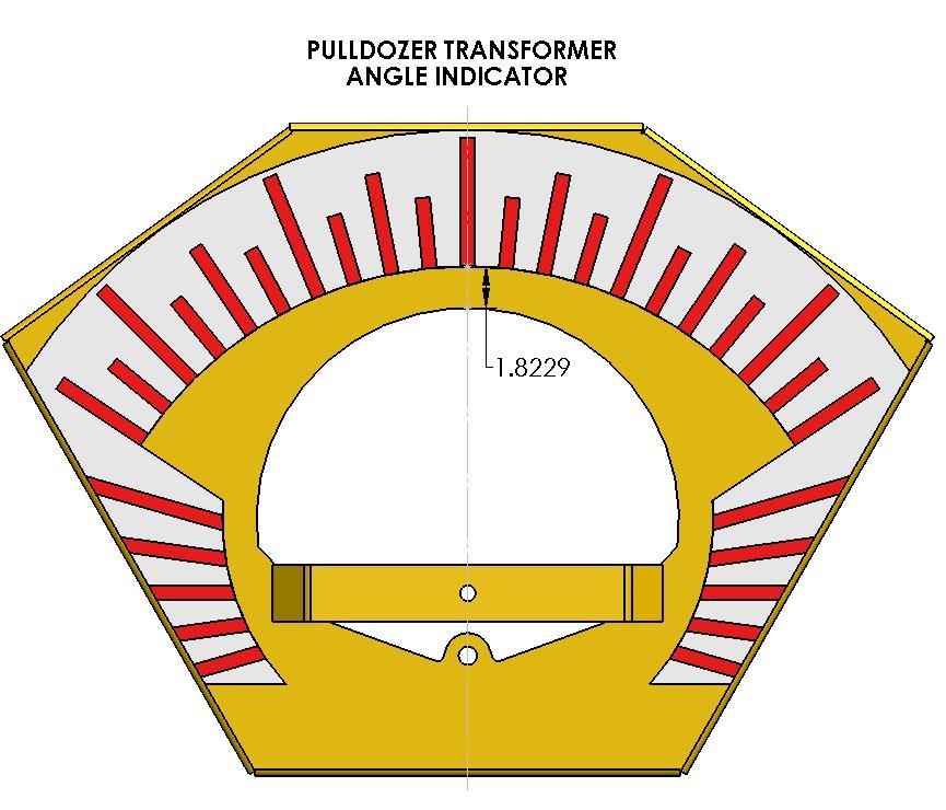
65 Angle Indicator: Center and install decal (26649) onto indicator bracket (272012) Insert brass bushing (10005) into indicator needle (272031) Install arm onto bracket using brass bushing, 3/4" x 4" bolt (15578) and 3/4" lock nut (10007). DO NOT OVERTIGHTEN - Arm must swivel freely Install one end of the PTO cable (22958) through the slotted hole in the bracket and insert the ball joint (22955) into the bracket and tighten in place using two 5/8" nuts (10275) Install the clevis end of the cable (22957) to the arm using the supplied pin and cotter pin. NOTE: There are two different holes, depending on which size machine you have. Install one end of the spring (11787) into the needle, then through the clip on the bracket Leave the clevis jam nut loose until the final adjustment is complete Figure 4 - Angle indicator assembly BRIDGEVIEW MANUFACTURING INC. 65
66 Angle Indicator: Loosely route the cable alongside the main frame towards the back of the machine. Install the eyeball and clevis of the cable as per the top side ft Cable Figure 5 - Angle indicator attachment Along the side of the main frame, install a clamp to tie the cable down. Use a three 3/8" x 1" bolts (13806) and three cable clamps (13629) as shown. Figure 6 - Angle cable assembly Cable clamp BRIDGEVIEW MANUFACTURING INC. 66


67 Cable to be routed ON TOP of grade indicator Push-Pull Cable (22958) Figure 7 - Angle cable assembly If the indicator needle does not read "center" when the blade is perfectly level, it can be adjusted by loosening the jam nut on one of the clevises, removing the pin and threading the clevis either in or out. Start off with the dimension shown below then adjust accordingly. Tighten the jam nuts when finished adjustment. Centered Figure 8 - Angle arm adjustment BRIDGEVIEW MANUFACTURING INC. 67

68 Jam Nut Clevis Figure 9 - Clevis adjustment BRIDGEVIEW MANUFACTURING INC. 68
69 Height Indicator: Loosely route the cable on the left-hand side of the middle blade, through the access hole ft Push-Pull Cable (26900) Cable clamp (x2) Figure 10 - Height cable assembly Along the left side of the middle blade, install a clamp to tie the cable down. Use two 3/8" x 1" bolts (13806) and two cable clamps (13629) as shown. Figure 11 - Height cable assembly BRIDGEVIEW MANUFACTURING INC. 69


70 When the lift cylinders are fully stroked the height indicator arm should be at the top of decal as shown below, if it is not adjusted by loosening the jam nut on one of the clevises and threading the clevis either in or out. Tighten the jam nuts when finished adjustment. Figure 12 - Height indicator adjustment Jam Nut Clevis Figure 13 - Height indicator adjustment BRIDGEVIEW MANUFACTURING INC. 70
71 Grease Tube: The Pulldozer Transformer is equipped with grease hoses to make greasing more easier and user friendly. They are located near the machines lift pivot point shown below: BRIDGEVIEW MANUFACTURING INC. 71
72 3.6 Trencher Option NOTE: For machines with the optional trencher, the hitch section is replaced with a special hitch. All other steps remain the same. All following steps can be done at any time after the hitch is installed a) Place the trencher arm underneath of the hitch, then lift it up into place and insert the pin (22099). Lock the pin in place using two 3/4" x 5" bolts (10803) and Stover lock nuts (11823). Lastly, install two 1/4" self-tapping grease zerks (16364) into the holes in the pivot pipe. Fill with grease until pipe is full. Figure 14 - Trencher install BRIDGEVIEW MANUFACTURING INC. 72
73 b) Place the indicator sticker (26908) onto the depth indicator bracket (27200) with the arrow pointing up. Then install the bracket to the tabs on the top of the hitch using four 3/8" x 1" carriage bolts (15718) and serrated flange nuts (10271). c) Install the depth indicator arm (22137) to the tabs on the top of the hitch using a 1/2" x 3-1/4" (11782) bolt and 1/2" nylon lock nut (10241). The arm should pivot freely. Figure 15 - Depth indicator assembly d) Install the depth indicator linkage (23341) to the welded-on bolt on the ditcher (bushing end) using a 1/2" flat washer (11668) and nylon lock nut (10241). Install the other (slotted) end to the indicator arm using a 1/2" x 4-1/2" bolt (15574) and two serrated flange nuts (10273) to clamp the linkage. Make sure that the arm can still pivot up and down freely. The position within the slot will be set later. BRIDGEVIEW MANUFACTURING INC. 73
74 e) Install 5" x 24" hydraulic cylinders (20431) with the ram on the ditcher side and the ports down. Secure at both ends with a 1-1/4" cylinder pin (20688) and two 3/16" cotter pins (11670). Figure 16 - Trencher assembly f) Install 12MB - 8MJ90 fittings to each cylinder port, facing inwards and towards the front of the machine. Install two 8MJBH - 8MJT bulkhead tee fittings to the plate as shown, with the "tee" side towards the cylinders. BRIDGEVIEW MANUFACTURING INC. 74
75 Figure 17 - Trencher hydraulics g) Run the hydraulic hoses. See Figure 32 and 33 for hydraulic schematic, in the hydraulic assembly section. h) Connect a tractor and charge the hydraulics. With the blade and the trencher tip both touching the ground, set the depth indicator to read "0". Lift the trencher into transport position and insert the safety lock (22136) and the lock pin (12050). BRIDGEVIEW MANUFACTURING INC. 75
76 3.7 Decals DECAL LIST: Pulldozer Transformer: Slow Moving Vehicle Sign Angle Indicator Decal Red Reflective Decal (2" x 9") Yellow Reflective Decal RH Wing Position Indicator Decal LH Wing Position Indicator Decal Depth Indicator Decal 1 "Red Option" WHEAT FIST LEFT "FIST ///" RED WHEAT FIST RIGHT "FIST ///" RED Model-Specific: "1870" REAR AXLE 1870 "//// PULLDOZER 1870 ////" RED RIGHT HITCH, 1870 "FIST PULLDOZER 1870 \\\\" RED LEFT HITCH, 1870 "//// PULLDOZER 1870 FIST" RED "1870XL" TBA REAR AXLE 1870XL "//// PULLDOZER 1870XL ////" RED TBA RIGHT HITCH, 1870XL "FIST PULLDOZER 1870XL \\\\" RED TBA LEFT HITCH, 1870XL "//// PULLDOZER 1870XL FIST" RED BRIDGEVIEW MANUFACTURING INC. 76
77 INSTALLATION: BRIDGEVIEW MANUFACTURING INC. 77
78 BRIDGEVIEW MANUFACTURING INC. 78
79 BRIDGEVIEW MANUFACTURING INC. 79

80 BRIDGEVIEW MANUFACTURING INC. 80


81 - ASSEMBLY IS NOW COMPLETE - BRIDGEVIEW MANUFACTURING INC. 81

82 BRIDGEVIEW MANUFACTURING INC. 82

83 BRIDGEVIEW MANUFACTURING INC. 83
84 PULLDOZER TRANSFORMER NOTES BRIDGEVIEW MANUFACTURING INC. 84
PULLDOZER TRANSFORMER
 PULLDOZER TRANSFORMER 1850 1850XL Operator, Assembly & Parts Manual Last Updated: August 28, 2018 Bridgeview Manufacturing Inc. P.O. Box 4 Gerald, Saskatchewan, Canada S0A 1B0 Phone: 1-306-745-2711 Fax:
PULLDOZER TRANSFORMER
 PULLDOZER TRANSFORMER 1850 1850XL Operator, Assembly & Parts Manual Last Updated: July 20, 2017 Bridgeview Manufacturing Inc. P.O. Box 4 Gerald, Saskatchewan, Canada S0A 1B0 Phone: 1-306-745-2711 Fax:
PULLDOZER TRANSFORMER
 PULLDOZER TRANSFORMER 2450 2450XL Operator, Assembly & Parts Manual Last Updated: July 19, 2018 Bridgeview Manufacturing Inc. P.O. Box 4 Gerald, Saskatchewan, Canada S0A 1B0 Phone: 1-306-745-2711 Fax:
PULLDOZER 1800/1800XL/2400/2400XL
 PULLDOZER 1800/1800XL/2400/2400XL Assembly and Parts Manual Bridgeview Manufacturing Inc. P.O. Box 4 Gerald, SK S0A 1B0 (306) 745-2711 www.bridgeviewmanufacturing.com bmi@sasktel.net 2 1. Component Information
VR482 Hay Rake OPERATOR & PARTS MANUAL. Last Updated: May 12, 2014
 VR482 Hay Rake OPERATOR & PARTS MANUAL Last Updated: May 12, 2014 Bridgeview Manufacturing Inc. P.O. Box 4 Gerald, SK S0A 1B0 (306) 745-2711 www.bridgeviewmanufacturing.com bmi@sasktel.net Your Authorized
BALE KING VR483. Hay Rake. Operator's & Parts Manual. Last Updated: April 27, Bridgeview Manufacturing Inc.
 BALE KING VR483 Hay Rake Operator's & Parts Manual Last Updated: April 27, 2015 P.O. Box 4 Gerald, Saskatchewan, Canada S0A 1B0 Phone: 1-306-745-2711 Fax: 1-306-745-3364 Email: bmi@sasktel.net www.bridgeviewmanufacturing.com
PULLDOZER Scraper Pan Operator s & Assembly Manual. Last Updated: July 27, 2017
 1220 Scraper Pan Operator s & Assembly Manual Last Updated: July 27, 2017 Bridgeview Manufacturing Inc. P.O. Box 4 Gerald, Saskatchewan, Canada S0A 1B0 Phone: 1-306-745-2711 Fax: 1-306-745-3364 Email:
BALE KING GT40 Grain Feeder Operator's & Parts Manual Last Update: November 20, 2014 Bridgeview Manufacturing Inc - 1 -
 BALE KING GT40 Grain Feeder Operator's & Parts Manual Last Update: November 20, 2014 Bridgeview Manufacturing Inc - 1 - Your Authorized Dealer: Your Serial Number: The Serial Number is located on the tank.
BALE KING VORTEX 3110 BALE KING GREEN & DEGELMAN BALE KING YELLOW MODELS
 PARTS MANUAL BALE KING VORTEX 3110 BALE KING GREEN & DEGELMAN BALE KING YELLOW MODELS MANUFACTURED BY: BRIDGEVIEW MANUFACTURING INC. P.O. BOX 4 GERALD, SASK. CANADA S0A 1B0 PHONE: (306) 745-2711 FAX: (306)
BALE KING VORTEX 3100 HD BALE KING GREEN & DEGELMAN BALE KING YELLOW MODELS
 PARTS MANUAL BALE KING VORTEX 3100 HD BALE KING GREEN & DEGELMAN BALE KING YELLOW MODELS MANUFACTURED BY: BRIDGEVIEW MANUFACTURING INC. P.O. BOX 4 GERALD, SASK. CANADA S0A 1B0 PHONE: (306) 745-2711 FAX:
RITE WAY MFG. CO. LTD. P.O.
 CO. LTD. P.O. Box 328 Imperial, Saskatchewan Canada, S0G 2J0 Ph: (306) 963-280 Fax: (306) 963-2660 Web Site: www.ritewaymfg.com E-mail: info@ritewaymfg.com Table of Contents SPECIFICATIONS... WARNING...2
OPERATOR S MANUAL REPAIR PARTS CATALOG. Models: SCP-51 & SCP-71 SCP-52 & SCP-72 SCP-91 & SCP-111 SCP-92 & SCP-112 BRILLION FARM EQUIPMENT
 OPERATOR S MANUAL REPAIR PARTS CATALOG Subsoil Chisel Plow Models: SCP-51 & SCP-71 SCP-52 & SCP-72 SCP-91 & SCP-111 SCP-92 & SCP-112 IMPORTANT! Repairs cannot be purchased retail direct from factory. Order
PARTS MANUAL BALE KING V-RAKE VR810 GREEN AND YELLOW ITEM NUMBERS
 PARTS MANUAL BALE KING V-RAKE VR810 GREEN AND YELLOW ITEM NUMBERS MANUFACTURED BY: BRIDGEVIEW MANUFACTURING INC. P.O. BOX 4 GERALD, SASK. CANADA S0A 1B0 PHONE: (306) 745-2711 FAX: (306) 745-3364 TABLE
PARTS MANUAL VR 1214 BALE KING V-RAKE GREEN AND YELLOW NUMBERS
 PARTS MANUAL VR 1214 BALE KING V-RAKE GREEN AND YELLOW NUMBERS MANUFACTURED BY: BRIDGEVIEW MANUFACTURING INC. P.O. BOX 4 GERALD, SASK. CANADA S0A 1B0 PHONE: (306) 745-2711 FAX: (306) 745-3364 TABLE OF
KONGSKILDE 9200 DF Vertical Tillage - Assembly/Parts
 KONGSKILDE 9200 DF Vertical Tillage - Assembly/Parts Kongskilde 9200 *Model may not be exactly as shown. Kongskilde reserves the right to make changes to product designs and specifications without notice
HOW TO ORDER PARTS: Unless this is done, we cannot provide prompt service or assure shipment of the correct parts.
 How to Order Parts HOW TO ORDER PARTS: IMPORTANT Parts must be ordered through your local authorized ASHLAND dealer. Be sure to state MODEL and SERIAL NUMBER of your machine, PART NUMBER, DESCRIPTION and
ASSEMBLY MANUAL. 45-Foot Air Double Disc Drill. Amity Technology, LLC th Avenue North Fargo, ND (701)
") ASSEMBLY MANUAL 45-Foot Air Double Disc Drill Amity Technology, LLC 2800 7th Avenue North Fargo, ND 58102 (701) 232-4199 www.amitytech.com TABLE OF CONTENTS Main Frame 1 Wing Lock Towers 3 Wing Frames
ASSEMBLY MANUAL 45-Foot Air Double Disc Drill Amity Technology, LLC 2800 7th Avenue North Fargo, ND 58102 (701) 232-4199 www.amitytech.com TABLE OF CONTENTS Main Frame 1 Wing Lock Towers 3 Wing Frames
OPERATOR'S MANUAL & PARTS CATALOG 12 TON RUNNING GEAR
 Unverferth Grain Handling Systems OPERATOR'S MANUAL & PARTS CATALOG 1 TON RUNNING GEAR Model RGE- Unverferth Manufacturing Co., Inc. Box 7 Kalida, OH 8 Part No. 00 PH: 1-- FAX: 1--8 www.unverferth.com
BALE KING 5100/5100TR
 BALE KING 5100/5100TR Bale Processor Operator's & Parts Manual Last Updated: August 11, 2015 P.O. Box 4 Gerald, Saskatchewan, Canada S0A 1B0 Phone: 1-306-745-2711 Fax: 1-306-745-3364 Email: bmi@sasktel.net
STOP 42" HIGH SPEED LAWNSWEEPER. Owner's Manual. Model No's Safety Assembly Operation Maintenance Parts
 Owner's Manual STOP 42" HIGH SPEED LAWNSWEEPER Model No's. 486.242223 DO NOT RETURN TO STORE For Missing Parts or Assembly Questions Call 1-866-576-8388 CAUTION: Before using this product, read this manual
STOP. 44" High Speed Sweeper. Operator's Manual. Model No Safety Assembly Operation Maintenance Parts
 Operator's Manual STOP 44" High Speed Sweeper Model No. 486.029 DO NOT RETURN TO STORE For Missing Parts or Assembly Questions Call 1-866-576-8388 CAUTION: Before using this product, read this manual and
BALE KING 5200/5200TR
 BALE KING 5200/5200TR Bale Processor Operator's & Parts Manual Last Updated: February 2018 P.O. Box 4 Gerald, Saskatchewan, Canada S0A 1B0 Phone: 1-306-745-2711 Fax: 1-306-745-3364 Email: bmi@sasktel.net
By: Bale King Bale processor OPERATOR & PARTS MANUAL (NORTH-AMERICA)
") By: Bale King 6100 Bale processor OPERATOR & PARTS MANUAL WWW.BRIDGEVIEWMANUFACTURING.COM (NORTH-AMERICA) BRIDGEVIEW MANUFACTURING INC P.O BOX 4, HWY 22 GERALD, SASK. S0A 1B0 CANADA Ph: 306-745-2711 Fax:
By: Bale King 6100 Bale processor OPERATOR & PARTS MANUAL WWW.BRIDGEVIEWMANUFACTURING.COM (NORTH-AMERICA) BRIDGEVIEW MANUFACTURING INC P.O BOX 4, HWY 22 GERALD, SASK. S0A 1B0 CANADA Ph: 306-745-2711 Fax:
PARTS MANUAL. HD4SR and 12SR Auto Align Bale Skoop to 2017 K
 PARTS MANUAL 1998 to 2017 HD4SR and 12SR Auto Align Bale Skoop K34991-04 Table of Contents Section 1: Parts Breakdown...1-1 Bale Skoop Final Assembly... 1-2 Loader Assembly... 1-4 12SR - Grab Hook Assembly
THE TRACTOR AND/OR LOADER (IF EQUIPPED)
") THE TRACTOR AND/OR LOADER (IF EQUIPPED) Read the tractor and/or loader operator s manual to learn how to operate your tractor and/or loader safely. Failure to do so could result in serious injury or death
THE TRACTOR AND/OR LOADER (IF EQUIPPED) Read the tractor and/or loader operator s manual to learn how to operate your tractor and/or loader safely. Failure to do so could result in serious injury or death
Wheel Horse. 36 Tiller. Model No & Up. Operator s Manual
 FORM NO. 8 9 Rev. A Wheel Horse 6 Tiller for Classic Garden Tractors Model No. 7970 690000 & Up Operator s Manual IMPORTANT: Read this manual carefully. It contains information about your safety and the
4200 & 6200 Owner s Manual & Parts Book
 00 & 00 Owner s Manual & Parts Book Purchase Date Serial Number Model Number Tractor Model PN: - Dealer Date --0 Description Page To The Owner & Maintenance Safety Precautions & Torque Specifications Skid
Operator s/parts Manual
 Operator s/parts Manual 3-Point Solid Stand Drills Pull Hitch Package Manufacturing, Inc. P.O. Box 5060 Salina, Kansas 67402-5060! Read the operator s manual entirely. When you see this symbol, the subsequent
TT8101 Rotary Tedder
 TT0 Rotary Tedder Illustrated Parts Breakdown Page Front End Page Page Transport Axle Assembly Cylinder Linkage Page Guards Page Page Page Page Transport Lock Assembly Lift Frame Assembly Center Tunnel
HT46X Rotary Tedder. Illustrated Parts Breakdown. Center Section
 HTX Rotary Tedder Illustrated Parts Breakdown Page Page Page Page Page Page Page Page Page Page 0 Page Center Section Hydraulics Outer Wing Assembly Center Bolted Components Tine Rotor and Hardware Tilt
FIELD ADJUSTMENTS THREE POINT 2020F, 2520F, 2025F, 2525F DRILL MAINTENANCE
 FIELD ADJUSTMENTS THREE POINT 2020F, 2520F, 2025F, 2525F DRILL MAINTENANCE Proper servicing and adjustment is the key to the long life of any farm implement. With careful and systematic inspection of your
Wheel Horse 48 Blade for 5xi Garden Tractors
 Form No. -9 Wheel Horse 8 Blade for 5xi Garden Tractors Model 7955 0000000 Operator s Manual Domestic English (EN) Contents Page Introduction................................ Installation.................................
530B ECOLO-TIGER MULCH CHISEL WARNING AND TAILIGHT KIT ECOLO-TIGER 530B
 04-01 WARNING AND TAILIGHT KIT ECOLO-TIGER 530B 04-01 WARNING AND TAILIGHT KIT ECOLO-TIGER 530B 2 27602311 1 HARNESS, WIRE, Front 3 27602221 1 HARNESS, WIRE, Rear (530B) 4 27602202 2 LIGHT ASSY., Red 5
TT4100 Rotary Tedder
 TT0 Rotary Tedder Serial numbers 0 and higher Illustrated Parts Breakdown Page Page Tongue Assembly S/N - Tongue Assembly S/N to Page Page Page Page Page Tongue Assembly S/N to Tongue Assembly S/N + Main
KONGSKILDE Vertical Tillage - Assembly Guide ASSEMBLY INSTRUCTIONS Revision 18 Serial No current Series.
 KONGSKILDE 9100 Vertical Tillage - Assembly Guide Kongskilde 9100 Series *Model may not be exactly as shown. Kongskilde reserves the right to make changes to product designs and specifications without
MidCap Rotary Rake. Illustrated Parts Breakdown
 MidCap Rotary Rake Illustrated Parts Breakdown Page Page Page Page Page Page Page Page Page Page 0 Page Page Page Page Page Page Page Page Page Main Frame Transport Wheel Assembly Lift Arm Assembly Main
Wheel Horse. 44 Snowthrower. for 5xi Lawn and Garden Tractors. Model No & Up. Operator s Manual
 FORM NO. 8 Rev A Wheel Horse Snowthrower for 5xi Lawn and Garden Tractors Model No. 7966 890050 & Up Operator s Manual IMPORTANT: Read this manual, and your tractor manual, carefully. They contain information
TT4101 Rotary Tedder
 TT Rotary Tedder 0//0 Illustrated Parts Breakdown Page Page Page Page Page Page Page Page Page Page Page Tongue Assembly S/N S/N - Tongue Assembly S/N + Main Frame S/N - Main Frame S/N to Main Frame S/N
B-BP-4 BALLPARK 4 GROOMER
 B-BP-4 BALLPARK 4 GROOMER TABLE OF CONTENTS 01 Ballpark 4 Cover Page 02 Table of Contents 03 Warranty 04 General Information & Tool Functions 05 Tool Adjustments & Basic Maintenance 06 How to Use the Ballpark
BUSH HOG LAND MAINTENANCE REPAIR PARTS MANUAL MODEL: TD-1100 SECTION: 66
 BUSH HOG LAND MAINTENANCE REPAIR S MANUAL MODEL: TD-00 SECTION: 0 Griffin Ave. Selma, AL 0 () - () -00 Parts Ordering -00-0- Fax -00-- www.bushhog.com BUSH HOG/ LAND MAINTENANCE REPAIR S MANUAL JUNE, 00
B-DM-6 Diamond Master Operation & Parts Manual Model no.: B-DM-6
 B-DM-6 Diamond Master Operation & Parts Manual Model no.: B-DM-6 TABLE OF CONTENTS 01 Cover Page 02 Table of Contents 03 Warranty 04 Diamond Master Information & Basic Maintenance 05 Adjustment of Tools
ROTARY RAKE PARTS BOOK MODEL E
 ROTARY RAKE PARTS BOOK MODEL 1150 17.00803E This parts book is furnished for your convenience only. All parts must be purchased through an authorized dealer. Call us for a dealer near you. Issue Date:
Champion Series Zero-Turn Riders & Mower Decks
 Parts Manual Champion Series Zero-Turn Riders & Mower Decks HP Tractors Mfg. No. Description Champion, HP Zero-Turn Rider Champion, HP Zero-Turn Rider (CE) 0HP Tractors Mfg. No. Description Champion, 0HP
TWIN ROTARY RAKE PARTS BOOK MODEL
 TWIN ROTARY RAKE PARTS BOOK MODEL 2650 17.01135 This parts book is furnished for your convenience only. All parts must be purchased through an authorized dealer. Call us for a dealer near you. Issue Date:
<THESE INSTRUCTIONS MUST BE GIVEN TO THE END USER> B&W
 B&W Trailer Hitches 6 Hawaii Rd / PO Box 86 Humboldt, KS 66748 P:60.473664 F:60.869.903 Turnoverball Gooseneck Hitch Installation Instructions MODEL 08
Drive End Bracket & Bearing. Drive End Bracket. Tandem Axle # #865733
 Drive End Bracket & Bearing #865089 1 06409700 1" Lock Collar 2 865733 Drive Bracket w/ Bearing 3 310037 End Drive Shaft Drive End Bracket #865733 1 03003100 Bearing 1" w/snap Ring 2 957795 Drive End Bracket
450 & Slant Top Owner s Manual & Parts Book
 0 & 0 - Slant Top Owner s Manual & Parts Book Purchase Date Serial Number Model Number Tractor Model PN: - Dealer Date -- Contents Description Page To The Owner & Maintenance Safety Precautions & Torque
Mulching and Finishing Mowers MP and FP
 Mulching and Finishing Mowers MP and FP Parts Manual Locke Turf 0 Highway E, Opp, Alabama, () -00 Transport Wheel, Tire & Spindle MP and FP ALPHABETICAL INDEX CONTENTS PAGE 00 Hydraulic Cylinder (Rear)
FIELD ADJUSTMENTS THREE POINT 1510HDF, 2010HDF, & 2510HDF DRILL MAINTENANCE
 FIELD ADJUSTMENTS THREE POINT 1510HDF, 2010HDF, & 2510HDF DRILL MAINTENANCE Proper servicing and adjustment is the key to the long life of any farm implement. With careful and systematic inspection of
RW 1200 ROCK WINDROWER. Table of Contents
 RITE WAY MFG. CO. LTD. P.O. Box 328 Imperial, Saskatchewan Canada, S0G 2J0 Ph: (306) 963-2180 Fax: (306) 963-2660 Web Site: www.ritewaymfg.com E-mail: info@ritewaymfg.com RW 1200 ROCK WINDROWER Table of
END WHEEL NO- TILL 706NT & 1006NT
 END WHEEL NO- TILL 706NT & 1006NT DRILL MAINTENANCE Proper servicing and adjustment is the key to the long life of any farm implement. With careful and systematic inspection of your grain drill, you can
Illustrated Parts List I HDC 1000 ( ) Repair Parts Manual
 Repair Parts Manual") Illustrated Parts List 2008-01 I0807212 531 03 10-07 HDC 1000 (45-01714-669) Repair Parts Manual owners manual Model No. 45-01714-669 10 CU. FT. CART CAUTION: Read Rules for Safe Operation and Instructions
Illustrated Parts List 2008-01 I0807212 531 03 10-07 HDC 1000 (45-01714-669) Repair Parts Manual owners manual Model No. 45-01714-669 10 CU. FT. CART CAUTION: Read Rules for Safe Operation and Instructions
36 Tiller Wheel Horse Lawn and Garden Tractor Attachment
 Form No. 9 6 Rev B 6 Tiller Wheel Horse Lawn and Garden Tractor Attachment Model No. 797 890000 and Up Operator s Manual English(En) Contents Page Introduction................................ Safety.....................................
Parts Book 612N, 812N, 642N, 842N, 862N 714NT, 814NT, 742NT, 842NT, 862NT
 Parts Book 612N, 812N, 642N, 842N, 862N 714NT, 814NT, 742NT, 842NT, 862NT Wishek Mfg. LLC 112 South 2nd Street PO Box 185 Wishek, ND 58495 (701) 452-2449 www.wishekmfg.com WARRANTY/ PARTS RETURN POLICY
Wheel Horse. 48 Snow/Dozer Blade. Model No & Up. Operator s Manual
 FORM NO. 9 878 Rev A Wheel Horse 8 Snow/Dozer Blade for 5xi Lawn and Garden Tractors Model No. 7955 890000 & Up Operator s Manual IMPORTANT: Read this manual, and your tractor manual, carefully. They contain
KONGSKILDE 8200 DF Field Cultivator - Assembly/Parts
 KONGSKILDE 8200 DF Field Cultivator - Assembly/Parts Kongskilde 8200 Models 768236901 8236 Field Cultivator (36.5') 768238901 8238 Field Cultivator (38.5') 768240901 8240 Field Cultivator (40.5') 768242901
OPERATOR'S MANUAL & PARTS LIST
 GRAVITY GRAIN BOES OPERATOR'S MANUAL & PARTS LIST GRAVITY GRAIN BOES Model 50 (After Serial #14860 & D-Series) Model 85 (After Serial #C104749 & D-Series) Model 90 (After Serial #D0580100 & Up) Model 450
INSTALLATION OF RAILGEAR KIT R-290HD REAR
 INSTALLATION OF RAILGEAR KIT R-290HD REAR Page 1 of 29 SAFETY PRECAUTIONS If any installation problems are encountered, please call G&B Specialties, Inc. for technical assistance before continuing with
MODEL NO & UP
 FORM NO. 97 50xi GARDEN TRACTOR MODEL NO. 7570 990000 & UP SET UP INSTRUCTIONS Loose Parts Use the chart below to identify parts for assembly. DESCRIPTION QTY. USE Rear Wheel Wheel Bolt R.H. Wheel Spindle
OWNERS MANUAL. Model No LB. TOW BROADCAST SPREADER. CAUTION: Read Rules for Safe Operation and Instructions Carefully
 OWNERS MANUAL APPLICATION TIPS xxxxxxxxxxxxxxxxxxxxxxxxxxxxxxxxxxxxx xxxxxxxxxxxxxxxxxxxxxxxxxxxxxxxxxxxxxxxxxx xxxxxxxxxxxxxxxxxxxxxxxxxxxxxxxxxxxxxxxxxxx xxxxxxxxxxxxxxxxxxxxxxxxxxxxxxxxxxxxxxxxx xxxxx
tRIPr Chief Grain Cart. Operator s Manual. Operator s Manual
 125-000-01 125-000-01 1tRIPr 1tRIPr Operator s Manual 1210 Chief Grain Cart Operator s Manual Operator s Manual TO THE DEALER Predelivery/Delivery Checklist 1210 Grain Cart PREDELIVERY/DELIVERY CHECKLIST
SAFETY. Hitchpole, centre frame 1. Centre frame wheels & roller 3. Centre & wing frames 5. Wing frame wheels & roller 9.
 MANUAL Hitchpole, centre frame 1 Centre frame wheels & roller 3 Centre & wing frames Wing frame wheels & roller 9 Hydraulics 11 Clearance lights 13 Operations 1 Safety, warranty 1 SAFETY Industrial Drive,
Opera.
 Diamond Master Model no.: B DM 66 Opera ation & Parts Manual GORDON BANNERMANN LIMITED T: (416) 247 7875 F: (416)) 247 6540 www.sportsturfmagic..com Page 2 Table of Contents Cover Page 1 Table of Contents
OWNER'S MANUAL MODEL NO Safety Assembly Operation Maintenance Repair Parts. Read Rules for Safe Operation and Instructions Carefully
 OWNER'S MANUAL MODEL NO. 45-05191 Utility 17 Poly Cart CAUTION: Read Rules for Safe Operation and Instructions Carefully Safety Assembly Operation Maintenance Repair Parts the fastest way to purchase parts
250P Manure Spreader
 0P Manure Spreader Illustrated Parts Breakdown Page - Page Page Page Page Page Page Page Page Page Page Page Page Page Page - Page Page Page 0 Complete Front End PTO/Jack/Hitch Assembly Front Pulley Assembly
2. PREPARATION 1. SAFETY 3. FRAME 4. TRANSMISSION 5. DRIVE 6. ROW UNIT 7. OPTIONAL EQUIPMENT
 TABLE OF CONTENTS 1. SAFETY 2. PREPARATION 3. FRAME 4. TRANSMISSION 5. DRIVE 6. ROW UNIT 7. OPTIONAL EQUIPMENT For the initial preparation of the planter, lubricate the planter and row units. Make sure
TT6101 Rotary Tedder
 TT0 Rotary Tedder 0/0/0 Illustrated Parts Breakdown Page Chassis Assembly Page Page Transport Axle Assembly S/N - Transport Axle Assembly S/N + Page Page Page Page Page Transport Lock Assembly Lift Frame
OWNER'S MANUAL MOBILE LIFT:
 : 18"MODELS-(19675 & 24565) OR 24" MODELS-(20565, 24570, & 24770) INSTALLATION AND OPERATION INSTRUCTIONS -SERVICE AND PARTS INFORMATION IMPORTANT A class III frame receiver hitch must be installed by
INSTALLATION INSTRUCTIONS
 INSTALLATION INSTRUCTIONS WARNING: NEVER EXCEED YOUR VEHICLE MANUFACTURER'S RECOMMENDED TOWING CAPACITY PIN-STYLE TRUNNION BAR WEIGHT DISTRIBUTION KIT MAINTENANCE Keep the socket-mounted ends of the spring
Multi-Ject Aerator Model no.: BA-400 Operation & Parts Manual
 Multi-Ject Aerator Model no.: BA-400 Operation & Parts Manual P a g e 2 Table of Contents Cover Page 1 Table of Contents 2 Welcome to Bannerman 3 Warranty 4 Work Safety 5 Three Point Hitch Attachment Procedure
2. PREPARATION 1. SAFETY 3. FRAME 4. TRANSMISSION 5. DRIVE 6. ROW UNIT 7. OPTIONAL EQUIPMENT Monosem Inc.
 TABLE OF CONTENTS 1. SAFETY 2. PREPARATION 3. FRAME 4. TRANSMISSION 5. DRIVE 6. ROW UNIT 7. OPTIONAL EQUIPMENT For the initial preparation of the planter, lubricate the planter and row units. Make sure
Part Number Published 08/ Series Blade. 181 Series Blade
 141 SERIES 181 SERIES Published 08/15 Part Number 50076192 141 Series Blade 181 Series Blade To the Owner/Operator/Dealer All implements with moving parts are potentially hazardous. There is no substitute
OWNERS MANUAL. Model No LB. PUSH BROADCAST SPREADER. Assembly Operation Maintenance Repair Parts
 OWNERS MANUAL Model No. 45-02102-101 SHIELD UP - 8 TO 18 FT. SPREAD WIDTH SHIELD DOWN - 3 TO 4 FT. SPREAD WIDTH 125 LB. PUSH BROADCAST SPREADER CAUTION: Read Rules for Safe Operation and Instructions Carefully
RZT TWIN STICK HYDRO DRIVE 250 Z 44" & 50" SERIES 0
 Parts Manual for RZT TWIN STICK HYDRO DRIVE 250 Z 44" & 50" SERIES 0 MODEL ERZT185440BVE RZT22500BVE2 McDonough, GA, 30253 U.S.A. COPYRIGHT 2006 SNAPPER PRODUCTS, INC. ALL RIGHTS RESERVED. Revision 1,
3509 & 3511 BACKHOE 3-POINT HITCH / CATEGORY II PARTS MANUAL. Part Number: MODEL NUMBER: Rev. 4
 509 & 5 BACKHOE -POINT HITCH / CATEGORY II PARTS MANUAL SERIAL NUMBER: Manual Number: PM609 Part Number: 5509 MODEL NUMBER: Rev. 800-56-00 I www.paladinlcg.com 50 Gay Street, Delhi, IA 5, United States
OWNER S MANUAL. PTO Generator Trailer ITEM # For use on 13000, 27500, and PTOG North Star Generators or Other PTO Generators up to 60kW.
 PTO Generator Trailer ITEM # 165959 For use on 13000, 27500, and 60000 PTOG North Star Generators or Other PTO Generators up to 60kW. M165959C PLACE MANUAL NAMEPLATE HERE OWNER S MANUAL 00641 Any Questions,
INSTALLATION AND PARTS MANUAL MODEL 30B FOR NEW HOLLAND DC75, DC85, DC95X
 CARCO INSTALLATION AND PARTS MANUAL MODEL 30B FOR NEW HOLLAND DC75, DC85, DC95X NOTE: This manual covers mounting and control group installation, and parts specific to this winch on the specified tractor.
OPERATOR'S MANUAL 304 Row Mulcher
 OPERATOR'S MANUAL 0 Row Mulcher PUBLICATION DATE: // Millcreek Manufacturing Company Reservoir Road Honey Brook PA MILLCREEK PART# 0 WARNING: DO NOT assemble, operate, or maintain this equipment without
Illustrated Parts & Packing List & Instructions 815 Rice Lake Street, Owatonna, MN 55060
 Illustrated Parts & Packing List & Instructions 815 Rice Lake Street, Owatonna, MN 55060 Great Plains Part #891-561C (Gandy Part #6245DS-GP) For Great Plains Turbo-Max 2400, 3000, 3500 & 4000 Models 45
Model No EXPLORER POLY ATV CART. CAUTION: Read Rules for Safe Operation and Instructions Carefully
 owners manual Model No. 45-01753 EXPLORER POLY ATV CART CAUTION: Read Rules for Safe Operation and Instructions Carefully IMPORTANT! The wheel bearings are not prelubricated. The wheel hubs must be filled
CHAINGUARD REGAL ST COLOR
 DESOTO/ REGAL HAULER PARTS LIST Item Part # Description QTY Item Part # Description QTY 1 11871 REFLECTOR KIT TRIKE 1 32 11764 FENDER BRACE 24" MWT 1 2 12199 SCREW #14 x 3/4 4 33 12176 NUT5/16-24 HEX 2
MODEL L-9, L-10 LAND LEVELER INDEX
 HOW TO ORDER PARTS: MODEL L-9, L-10 LAND LEVELER Be sure to state MODEL and SERIAL NO. of machine, PARTS NO., DESCRIPTION, and QUANTITY wanted. Unless this is done, we cannot provide prompt service or
Sync-Row for MONOSEM Twin-Row. Setting the Twin-Row Stagger INSURE THESE VALUES ARE CORRECT FOR YOUR TWIN ROW PLANTER
 Sync-Row for MONOSEM Twin-Row TIMING CHART 30" ROW SPACING Chart for Adjustable Metering Sprocket INSURE THESE VALUES ARE CORRECT FOR YOUR TWIN ROW PLANTER Crop Corn Number of Seed Disk Cells (holes) 18
MODEL 328 (306) : 8190 JUMBO HEAVY HARROW
 : 8190 JUMBO HEAVY HARROW") P. O. Box 328 Imperial, Saskatchewan Canada, S0G 2J0 PH: (306) 963-2180 Web Site: www.ritewaymfg.com E-mail: info@ritewaymfg.com 90 Solid Draft Arm Table of Contents INTRODUCTION... 1 SPECIFICATIONS...
P. O. Box 328 Imperial, Saskatchewan Canada, S0G 2J0 PH: (306) 963-2180 Web Site: www.ritewaymfg.com E-mail: info@ritewaymfg.com 90 Solid Draft Arm Table of Contents INTRODUCTION... 1 SPECIFICATIONS...
MAINTENANCE WEIGHT RATINGS WARNINGS. warning: never exceed your vehicle manufacturer's recommended towing capacity
 Installation instructions warning: never exceed your vehicle manufacturer's recommended towing capacity Round Bar WEIGHT DISTRIBUTION kit MAINTENANCE Keep the socket-mounted ends of the spring bars and
! CAUTION! ! WARNING!
 Assembly Instructions! 24- and 30-Foot, No-Till Flat Fold Marker Option Used with: 2N-2410 and 2N-3010 Drills 2N-2420 and 2N-3020 Drills When you see this symbol, the subsequent instructions and warnings
CHAINGUARD REGAL ST COLOR
 DESOTO/ REGAL HAULER PARTS LIST Item Part # Description QTY Item Part # Description QTY 1 11871 REFLECTOR KIT TRIKE 1 32 11762 FENDER BRACE 20" MWT 1 2 12199 SCREW #14 x 3/4 4 11764 FENDER BRACE 24" MWT
ALL PLANT & MIN TILL DRILL
 4000 SERIES ALL PLANT & MIN TILL DRILL OWNER S MANUAL ADDENDUM OPERATION MAINTENANCE REPAIR PARTS #608869 (03-08) 2 Table of Contents Precision Planting Metering System 5-9 Precision Planting Introduction
PRE-DELIVERY INSPECTION CHECK LIST
 PRE-DELIVERY INSPECTION CHECK LIST General Remove wrapping and wash unit, removing all road debris. (Road salt, mud, snow, etc.) Inspect paint, decals and general appearance of unit. Verify that the owner
4 Wheel Steer Header Transports
 4WS15 4WS17 OPERATORS MANUAL Rev. 5.31.2017 4 Wheel Steer Header Transports J. & M. Mfg. Co., Inc. 284 Railroad Street - P.O. Box 547 Fort Recovery, OH 45846 Ph: (419) 375-2376 Fax: (419) 375-2708 www.jm-inc.com
NEVER STOP CORRUGATE OPENER
 NEVER STOP CORRUGATE OPENER CORRUGATE OPENER PRE.-DELI VERY SET UP The Never Stop has been fully assembled and tested prior to delivery. Upon receipt of this machine it is necessary to check and tighten
Walker Loader Bucket OPERATOR S AND PARTS MANUAL
 Walker Loader Bucket OPERATOR S AND PARTS MANUAL Please Read and Save These Instructions For Safety, Read all Safety and Operation Instructions Prior To Operating Machine P/N 6690 TABLE OF CONTENTS Introduction
Model 3770 WARNING. Failure to comply with the safety information in these instructions could result in serious injury or death.
 B&W Trailer Hitches 1216 Hawaii Road / PO Box 186 Humboldt, KS 66748 P:620.473.3664 See Limited Lifetime Warranty at F:620.869.9031 bwtrailerhitches.com/warranty NOTE: We recommend reading instructions
2800 VIBRO-TILL FIELD CULTIVATOR ASSEMBLY INSTRUCTIONS Series. Kongskilde
 2800 VIBRO-TILL FIELD CULTIVATOR Kongskilde 2800 Series *Model may not be exactly as shown. Kongskilde reserves the right to make changes to product designs and specifications without notice or obligation
LAND MAINTENANCE REPAIR PARTS MANUAL BUSH HOG MODEL: 307 SECTION: 16
 BUSH HOG LAND MAINTENANCE REPAIR S MANUAL MODEL: 0 SECTION: P.O. Box 0 Selma, AL 0-0 () - () -00 Parts Ordering -00-0- Fax -00-- www.bushhog.com BUSH HOG / LAND MAINTENANCE REPAIR S MANUAL SEPTEMBER, 0
<THESE INSTRUCTIONS MUST BE GIVEN TO THE END USER> B&W
 B&W Trailer Hitches 1216 Hawaii Rd / PO Box 186 Humboldt, KS 66748 P:620.473.3664 F:620.869.9031 Turnoverball Gooseneck Hitch Installation Instructions
MODEL 345 SERIES II FLAT BED PLASTIC MULCH LAYER OPERATING MANUAL
 MODEL 345 SERIES II FLAT BED PLASTIC MULCH LAYER OPERATING MANUAL Rain-Flo Irrigation 929 Reading Road East Earl, Pa 17519 PH: 717-445-3000 Table Of Contents Cover Disk... 5 Dirt Shield... 5 Drip Pipe...
OPERATOR S MANUAL REPAIR PARTS CATALOG. with ONE & TWO SHANKS BRILLION FARM EQUIPMENT
 OPERATOR S MANUAL REPAIR PARTS CATALOG Subsoil Chisel Plow with ONE & TWO SHANKS MODELS: SCP-1 SCP-2 IMPORTANT! Repairs cannot be purchased retail direct from factory. Order through your Brillion dealer.
Land Cruiser FJ80 and FZJ80 Double Swingout Rear Bumper Installation Instructions PRELIMINARY
 Land Cruiser FJ80 and FZJ80 Double Swingout Rear Bumper Installation Instructions Fits 1991-1997 80 Series Land Cruiser / Lexus LX450 PRELIMINARY Thank you for purchasing a Rear Bumper for your Land Cruiser.
PFadvantage JD 3300/4400/6600/7700; 4420
 Ag Leader Technology Combine Installation JD 33//66/77; 2 Note: Indented items indicate parts included Quantity by Model in an assembly listed above Early Late Part Name/Description Part Number 3 3 6 6