A robot is a programmable mechanical device that can perform tasks and interact with its environment, without the aid of human interaction
|
|
|
- Michael Strickland
- 5 years ago
- Views:
Transcription


1 Welcome to... T H E

2
3 A robot is a programmable mechanical device that can perform tasks and interact with its environment, without the aid of human interaction
4 1. How to Plan
 Research Brainstorm Select an approach")

 See if the solution")
5 The Design Process Create a Design Brief (shown on the next slide) Research Brainstorm Select an approach Create a detailed design solution Create a technical drawing Write some pseudocode Construct the robot Program robot behavior Iterative development (This will take the longest amount of time) See if the solution actually works [1] [2]

6 Instructions for building a solution to a problem is called build instructions in Robotics: Problem Statement Robotic Engineers need a quick and easy way to confirm the working functionality of all programmable robotic components before they are deployed on a project. Upon conducting research, it turns out that our problem has already been solved and it s freely distributed as build instructions: Design Statement Design a tool that can accomodate all common programmable robotic components including motors for proper testing of functionality. Criteria 1. Robust 2. Reusable 3. Expandable S O L V E D The discovered solution fully satisfies our needs, and so our problem is considered invalid. Since the build instructions can be used, planning our own design isn t necessary.
7 2. How to Build


8 THE ROBOT DESIGN SYSTEM Structure Motion Sensorial Subsystem Subsystem Subsystem }


9 STRUCTURE. The Structural Subsystem of the robot is responsible for physical support. It holds everything in place, and is, in effect, the durable skeleton of the robot to which all the other subsystems are attached.


10 Metal Structure The parts in the Structure Subsystem form the base of every robot. These parts are the skeleton of the robot to which all other parts are attached. This subsystem consists of all the main structural components in the Design System including all the metal components and hardware pieces. These pieces connect together to form the skeleton or frame of the robot. Right Angle 2 Hole 3 Hole C-Channel 5 Hole Chassis Rail Bar Plate [3]
11 Screws Structure Size 8-32 The primary screws used to build robot structure. Size 6-32 Smaller screws which are used for special cases like mounting motors Screws Metal components can be directly attached together using 8-32 screws and nuts. Screws come in a variety of lengths and can be used to attach multiple thicknesses of metal together, or to mount other components onto structural pieces.

12 Nuts Structure When using screws to attach things together, there are three types of nuts which can be used. Nylock Nut KEPS Nut Regular Nut Have a plastic insert in them which will prevent them from unscrewing. These nuts will not come off due to vibration or movement Have a ring of teeth on one side of them. These teeth will grip the piece they are being installed on. These nuts are installed with the teeth facing the structure. Work great in most applications Have no locking feature. May loosen up over time, especially when under vibration or movement. Very thin and can be used in some locations where it is not practical to use a Nylock or KEPS nut.
13 Standoffs Structure Components can also be offset from each other using 8-32 threaded standoffs. Standoffs come in a variety of lengths and work great for mounting components as well as for creating structural beams Standoffs Typical use case for standoffs When designing a robot s structure, it is important to think about making it strong and robust while still trying to keep it as lightweight as possible. Sometimes overbuilding can be just as detrimental as underbuilding. The frame is the skeleton of the robot and should be designed to be integrated cleanly with the robot s other components. The overall robot design should dictate the chassis, frame, and structural design; not vice-versa. Design is an iterative process; experiment to find out what works best for a given robot.
14 ADDITIONAL TOPICS IN STRUCTURE Structure Center of Gravity Support Polygon Achieving Stability Exposure & Vulnerability

.")
15 Center of Gravity The average position of all the weight on the robot. Because it is an average of both weight and position, heavier objects count more than lighter ones in determining where the center of gravity is, and pieces that are farther out count more than pieces that are near the middle. Support Polygon The imaginary polygon formed by connecting the points where your robot touches the ground (usually the wheels). It varies by design, but there is always one support polygon in any stable configuration. Stability The robot will be most stable when the center of gravity is centered over the support polygon.


16 Inappropriate center of gravity The robot s center of gravity is no longer over the support polygon. The robot falls over as soon as it starts the ramp. The Center of Gravity is higher because of the new weight added to the top of the robot The Center of Gravity is now lower because the weight is mounted lower Appropriate center of gravity The robot s center of gravity is closer to the ground.
17 Exposure & Vulnerability Robot components that can be damaged are well shielded and inside robot structure. Route wires inside the robot and away from all moving components.


18 The Motion Subsystem of the robot is responsible for exactly that, motion. It includes both the motors that generate motion, and the wheels and gears that transfer and transform that motion into the desired forms. With the Structural Subsystem as the robot s skeleton, the Motion Subsystem is its muscle. MOTION.
.")
19 The Square Shaft Motion Most of the motion components use a square hole in their hub which fits tightly on square shafts. This square hole square shaft system transmits torque. Gear and Shaft Delrin Bearing The square shaft has rounded corners which allow it to spin easily in a round hole. This allows the use of simple bearings made from Delrin (a slippery plastic). The Delrin bearing will provide a low-friction piece for the shafts to turn in.

20 Actuators Motion The key component of any motion system is an actuator. An actuator is something which causes a mechanical system to move. There are two types of actuators: motors and servos. Both of them have different use cases. Each motor and servo comes with a square socket in its face, designed to connect to the square shafts. By simply inserting a shaft into this socket it is easy to transfer torque directly from a motor into the rest of the Motion Subsystem An Actuator (Both appear the same) Motor A standard motor spins its shaft around and around for as long as it s receiving power. Servo A servo rotates its shaft to a set angular position, between 0 and 120 degrees and holds it there for as long as it s receiving power. PROTECTING ACTUATORS FROM ABNORMAL SHOCK-LOADS Gears can break in some applications when an actuator is under significant load, over a short duration of time (a shock-load). Equipping the actuator with a clutch will prevent this from happening when an abnormal shock-load is applied. The clutch will absorb some of the energy in these situations by popping and giving way. This will protect the actuator.
21 Spacers & Collars Motion The Motion Subsystem also contains parts designed to keep pieces positioned on a shaft. These pieces include spacers and collars. Collars slide onto a shaft, and can be fastened in place using a setscrew. Before tightening the setscrew, it is important to slide the Collars along the square shafts until they are next to a fixed part of the robot so that the collar prevents the shaft from sliding back and forth

, after the")
22 Gears & Wheels Motion The primary way to transfer motion is through the use of spur gears. Spur gears transfer motion between parallel shafts, and can also be used to increase or decrease torque through the use of gear ratios. The last step in the drive train (series of gears transferring torque for the purpose of mobility), after the motors and gears, is the wheels. Bigger tires give you slower acceleration, while smaller tires give you faster acceleration.
23 ADDITIONAL TOPICS IN MOTION Motion Speed vs. Torque Gear Ratios Compound Gear Ratios Gear Ratios With Non-Gear Systems Idler Gears Linear Motion Lifts


24 Speed vs. Torque Because a motor can only generate a set amount of power, there is an inherent trade-off between Torque the force with which a motor can turn a wheel and Speed the rate at which a motor can turn a wheel. The exact configuration of torque and speed is usually set using gears. By putting different combinations of gears between the motor and the wheel, the speed-torque balance will shift. Gear Ratios Gear ratio can be thought of as a multiplier on torque and a divider on speed. A gear ratio of 2:1 would yield twice as much torque as a gear ratio of 1:1, but only half as much speed. Gear ratio is a ratio of the number of teeth on a driven gear to the number of teeth on its driving gear.
25 Compound Gear Ratios Compound gears are formed when two or more gears are on the same axle. In a compound gear system, there are multiple gear pairs. Each pair has its own gear ratio, but the pairs are connected to each other by a shared axle. The resulting compound gear system still has a driving gear and a driven gear, and still has a gear ratio (now called a compound gear ratio ). The compound gear ratio between the driven and driving gears is then calculated by multiplying the gear ratios of each of the individual gear pairs.

26 Gear Ratios With Non-Gear Systems Belt or chain drives are often preferred over gears when torque is needed to be transferred over long distances. When the number of teeth cannot be determined, gear ratio can be measured by the number of rotations on the driven and driving axles.


27 Idler Gears Gears can be inserted between the driving and driven gears. These are called idler gears, and they have no effect on the robot s gear ratio because their gear ratio contributions always cancel themselves out. However, idler gears do reverse the direction of spin. Normally, the driving gear and the driven gear would turn in opposite directions. Adding an idler gear would make them turn in the same direction. Adding a second idler gear makes them turn in opposite directions again.


28 Linear Motion Linear motion involves an object moving from one point to another in a straight line. Rotational motion involves an object rotating about an axis. Using a rack and pinion is one of the best ways to articulate a linear movement. This is known as a rack and pinion linear slide. Outer Linear Slide


29 Lifts A lift is a device that extends upwards. The Extension Lift is one type of lift and can be achieved different ways: Outer Linear Slide Rack & Pinion Chain Winch


30 Extension lifts can also be multi-stage to achieve greater height. Outer Linear Slide Continuous Rigging Cascade Rigging


31 The Scissor Lift is another type of lift. When the bottom of the scissors is pulled together it extends upwards. In this example a rack and pinion pulls the bottom of the scissors together. Outer Linear Slide


32 The Sensor Subsystem gives the robot the ability to detect various things in its environment. The sensors are the eyes and ears of the robot, and can even enable the robot to function independently of human control. SENSORIAL.
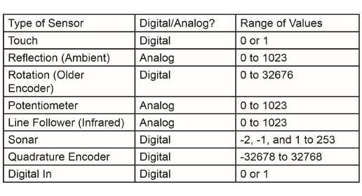
33 Analog vs. Digital Sensorial Analog Analog sensors communicate with the Microcontroller by sending it an electrical voltage along a wire. By measuring where the sent voltage falls between zero and maximum voltage, the Microcontroller can interpret the voltage as a numeric value for processing. Analog sensors can therefore detect and communicate any value in a range of numbers. States Range of numerical values Weakness Difficulty sending and maintaining an exact, specific voltage on a wire in a live circuit. Less reliable than Digital. Digital A digital sensor sends a voltage, just like an analog sensor, but instead of sending a voltage between zero and maximum, it will send only zero OR maximum. If the Microcontroller detects a voltage that is above a guaranteed Low or below a guaranteed High the results cannot be determined, it can be reported as a High or Low. States HIGH or LOW Weakness Can only indicate two values rather than a whole range.

34 Primitive vs. Smart Hardware Sensorial Starting in 2018, the VEX robot system has been shifting away from a primitive, low-level hardware design in turn for hardware that is more sophisticated and complex. Consequently, there is a line between hardware. Primitives The smallest most fundamental unit of hardware of a specific function in a robot. Smart Hardware Term used by the VEX robot system for hardware that uses the RJ-11 interface. This type hardware is more complex as it uses an collection of primitives to serve a more broad function. Vision Sensor Light Sensor Infrared Sensor Ultrasonic Sensor Smart Motor Potentiometer Shaft Encoder 393 Motor

 Full Speed (12 Mbit/s) Color Touch Screen 4.")

35 The Microcontroller Sensorial V5 Robot Brain Cortex Microcontroller Motor Ports Use any of the 21 Smart Ports 10 Smart Sensor Ports Radio Ports Use any of the 21 Smart Ports Use any of the 21 Smart Ports Tether Ports Use any of the 21 Smart Ports remove radios, use USB cable Digital Ports Use any of the 8 built-in 3-Wire Ports 12 Analog Ports Use any of the 8 built-in 3-Wire Ports 8 VEXos Processor One Cortex A9 at 667 MHz Two Cortex M0 at 32 MHz each One FPGA1 ARM7 User Processor One Cortex A Million Instructions per second (MIPS) Cortex M3 90 MIPS Ram 128 MBytes MBytes Flash 32 MBytes MBytes User Program Slots 8 1 USB 2.0 High Speed (480 Mbit/s) Full Speed (12 Mbit/s) Color Touch Screen 4.25, 480 x 272 pixels, 65k colors Expansion microsd up to 16 GB, FAT32 format Wireless VEXnet 3 and Bluetooth 4.2 VEXnet 2 System Voltage 12.8 V 7.2 V The Microcontroller is the brain of the robot. It s a fully programmable device, and is what enables motors, sensors, an LCD screen, and remote control signals to be connected. One of two can be used in a single robot.

36 The Cortex Microcontroller Sensorial Inside of the Cortex, there are two separate processors; a user processor handles program execution, and a master processor controls lower-level operations, like motor control and radio communication. Downloading the written programs to the Microcontroller uses a USB A-to-A cable as shown on the left. Plugged into computer for programming two motors.


37 The V5 Robot Brain Sensorial V5 uses a technology called Centralized Intelligence, which provides the user processor with all sensor information. All Smart Sensors have their own processor, which allows them to simultaneously collect and process data as fast as possible. New information is instantaneously sent to the user processor s high speed local RAM without interrupting the processor. Each time a line of code calls for sensor data as a user s program runs, such as motor position, the most recent calculation is instantly accessed from memory. Plugged into computer for programming two Smart motors. See all connected devices on one screen

 sound files.")

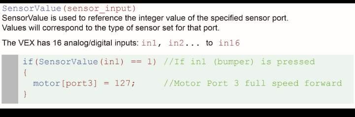
38 Wiring Up the Cortex Microcontroller Sensorial Analog Inputs Used by any sensors that provide a range of values. Examples include: Potentiometers Light sensors Line followers Accelerometers Digital Inputs/Outputs Digital ports are available for digital input signals. Examples include: Bumper switches Limit switches Ultrasonic range finders Optical shaft encoders. Speaker Output For connecting a single speaker. Enables the robot to play tones, sounds and wave (.wav) sound files. Interrupts Digital inputs designed for high priority signals that need immediate attention from the Microcontroller. These are used with some of the advanced sensors of the Robot Design System, such as the following: Ultrasonic Range Finder Quadrature Shaft Encoder Motor Outputs 2-wire motors and flashlights can be directly connected and controlled in ports 1 and wire motors and servos can be directly connected and controlled in ports 2 through 9. 2-wire motors and flashlights can be connected to ports 2 through 9 using a Motor Controller 29.


39 Wiring Up the V5 Robot Brain Sensorial RJ-11 The V5 Robot Brain has 21 Smart Ports available which enables the use of Smart hardware. Each of these are equipped with a digital circuit breaker, called an efuse, that allow for short circuit protection without limiting motor performance. 3-Pin Ports 3-Wire ports are multi-purpose. Any 3-Wire port can be a digital input, digital output, analog input, or PWM motor control. This enables the use of primitives: Bumper switches Limit switches Potentiometers Shaft Encoders Ultrasonic Sensors Light Sensors Infrared Sensors Accelerometers Gyroscopes 393 Motors


40 Bumper Switch Sensorial The bumper sensor is a physical switch. It tells the robot whether the bumper on the front of the sensor is being pushed in or not. When the switch is not being pushed in, the sensor maintains a digital HIGH signal on its sensor port. This High signal is coming from the Microcontroller. When an external force (like a collision or being pressed up against a wall) pushes the switch in, it changes its signal to a digital LOW until the switch is released. Pressed = 1 (or true) Unpressed = 0 (or false)


41 Limit Switch Sensorial The limit switch sensor is a physical switch. It can tell the robot whether the sensor s metal arm is being pushed down or not. When the limit switch is not being pushed in, the sensor maintains a digital HIGH signal on its sensor port. This High signal is coming from the Microcontroller. When an external force (like a collision or being pressed up against a wall) pushes the switch in, it changes its signal to a digital LOW until the limit switch is released. Pressed = 1 (or true) Unpressed = 0 (or false)


42 Ultrasonic Sensor Sensorial Ultrasonic refers to very high-frequency sound sound that is higher than the range of human hearing. Sonar, or Sound Oriented Navigation And Ranging, is an application of ultrasonic sound that uses propagation of these high frequency sound waves to navigate and detect obstacles. The ultrasonic sensor determines the distance to a reflective surface by emitting high-frequency sound waves and measuring the time it takes for the echo to be picked up by the detector. Distance to object = ½ (speed of sound) x (round trip delay)

43 Light Sensor Sensorial The light sensor uses a Cadmium Sulfoselenide photoconductive photocell, or CdS cell for short. The light sensor does what you think; it detects changes in light level. A low value (around 0) corresponds to very bright light, and a high value (around 255) corresponds to darkness.
44 Potentiometer Sensorial The Potentiometer is used to measure the angular position of the axle or shaft passed through its center. The center of the sensor can rotate roughly 265 degrees and outputs values ranging from to the Microcontroller. This measurement can help to understand the position of robot arms, or other mechanisms. Instructions for mounting the Potentiometer CAUTION When mounting the Potentiometer on your robot, ensure that the range of motion of the rotating shaft does not exceed that of the sensor. Failure to do so may result in damage to your robot and the Potentiometer. The arcs provide flexibility for the orientation of the Potentiometer, allowing the full range of motion to be utilized more easily.


 Two output channels (wires) are needed to transmit its")
45 Optical Shaft Encoder Sensorial Basic Optical Shaft Encoders are commonly used for position and motion sensing. Basically, a disc with a pattern of cutouts around the circumference is positioned between an LED and a light detector; as the disc rotates, the light from the LED is blocked in a regular pattern. This pattern is processed to determine how far the disc has rotated. If the disc is then attached to a wheel on a robot, it is possible to determine the distance that wheel traveled, based on the circumference of the wheel and the number of revolutions it made. The Encoder contains two optical sensors making it quadrature. This allows the sensor to detect if the internal disk is spinning clockwise or counterclockwise and increases the resolution to 360 counts per revolution (2 count intervals). (Only Channel 1 is connected) Two output channels (wires) are needed to transmit its sensor data. The term quadrature refers to the situation where there are two output channels; that is, two square waves 90 degrees out of phase with each other, being outputted by the unit.


46 V5 Smart Motor Sensorial Inside the motor are gears, an encoder, modular gear cartridge, circuit board, and thermal management components. Users can control the motor s direction, speed, acceleration, position, and torque limit. The motor s internal circuit board has a full H-Bridge and its own Cortex M0 microcontroller to measure position, speed, direction, voltage, current, and temperature. Feedback data in motor dashboard Cross section of a V5 Smart Motor

47 V5 Vision Sensor Sensorial At its most basic mode, the sensor tells you where a colored object is located. The location's X value gives you the right and left position. When the camera is tilted down, the Y value gives you the distance to the object, with a little basic trigonometry on your part. The Vision Sensor combines a dual ARM Cortex M4+M0 processor, color camera, WiFi, and USB into a single smart sensor. The sensor can be trained to locate objects by color. Every 200 milliseconds, the camera provides a list of the object found matching up to eight unique colors. The object s height, width, and location is provided. Multi-colored objects can also be programmed, allowing color codes to provide new information to the robot. Sample image location, six colors


48 Sense, Plan, Act (SPA) 1. SENSE The robot needs the appropriate hardware to sense important things about its environment, like the presence of obstacles or navigation aids. 2. PLAN The robot needs to take the sensed data and figure out how to respond appropriately to it, based on a pre-existing strategy. This pre-existing strategy is called behavior. Behavior is added by programming the Microcontroller. 3. ACT Finally, the robot must actually act to carry out the actions that the plan calls for. Sensorial Robotic Engineers use the Sense-Plan-Act concept to build robust robots that can operate in numerous environments, independent of human control. Program running on the robot
49 Programming the Robot Sensorial Two options exist for giving a robot behavior depending on which microcontroller used. C++/VEX Coding Studio VEX Coding Studio is an unlimited programming environment with all the capabilities of the VEX V5 Brain. Users have a full Industry Standard C++ environment available. C/RobotC RobotC is a C Programming Language for robotics. RobotC is also the name of the code editor that s used to write procedural code that is executed by the VEX Cortex microcontroller. The RobotC Natural Language API contains all the commands necessary to add behavior.
50 3. How to Program
51 RobotC and the Cortex Microcontroller


52 Variables Variables are places to store values (such as sensor readings) for later use, or for use in calculations. There are three main steps involved in using a variable: Declaration The variable is created by specifying its type, followed by its name. Here, it is a variable named speed that will store an integer. Assignment The variable is assigned a value using a =. The variable speed now contains the integer value 75. Use The variable can now stand in for any value of the appropriate type, and will act as if its stored value were in its place. Rules for Variable Types You must choose a data type that is appropriate for the value you want to store
53 Boolean Logic Comparison Operators Logical Operators More narrow, complicated conditions


54 If Statements An if-statement allows your robot to make a decision. When your robot reaches an if Statement in the program, it evaluates the condition contained between the parenthesis. If the condition is true, any commands between the braces are run. If the condition is false, those same commands are ignored

55 While Loops A while loop is a structure which allows a section of code to be repeated as long as a certain condition remains true.


56 Functions Function Parameterized Function (Parameterized) Return Function Declare Function Call Function Declare Parameter A parameter is declared similar to a variable (type & name) Use Parameter The parameter value behaves like a placeholder Call function with parameter Declare Return Type Indicate what type of value it will return Return Value Note the value that will be returned. Call function with parameter A function is a group of statements that are run as a single unit when the function is called from another location. Parameters are a way of passing information into a function. That value will typically influence how the function runs. It may help to think of the parameters as placeholders all parameters must be filled in with real values when the function. Not all functions are declared void. Sometimes a task might need information back out of the function at the end. The function will return a value, causing it to behave as if the function call itself were a value in the line that called it. SUBSTITUTIONS

57 Switch Case The switch-case command is a decision-making statement which chooses commands to run from a list of separate cases. A single switch value is selected and evaluated, and different sets of code are run based on which case the value matches. Switch statement The switch line designates the value that will be evaluated to see if it matches any of the case. Case statement The first line of a case includes the word case and a value. If the value of the switch variable (turnvar) matches this case value (1), the code following the case line will run. Commands These commands belong to the case 1, and will run if the value of the switch variable (turnvar) is equal to 1. Break statement Each case ends with the command break; Default case statement If the switch value above did not match any of the cases presented by the time it reaches this point, the default case will run.

 This loop will run while the timer s value is less than 3 seconds, i.e. less than 3 seconds have passed since the reset.")
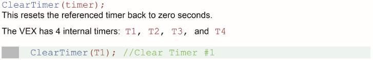
58 Timers Timers are very useful for performing a more complex behavior for a certain period of time. Clear the Timer Clearing the timer resets and starts the timer. You can choose to reset any of the timers, from T1 to T4. Timer in the (condition) This loop will run while the timer s value is less than 3 seconds, i.e. less than 3 seconds have passed since the reset. The line tracking behavior inside the {body} will continue for 3 seconds.


59 Reserved Words Reserved words (also known as keywords ) are provided directly by the RobotC Programming Language. Because they are a feature of the language itself, they will always be accessible, even without the Natural Language API. MOTORS

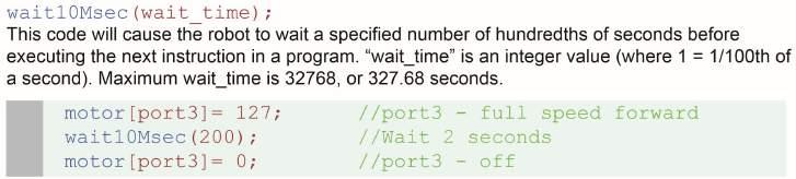
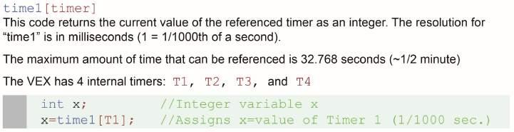
60 Reserved Words TIMING

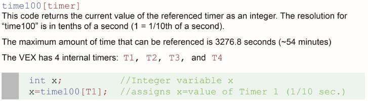
61 Reserved Words TIMING


62 Reserved Words SOUND RADIO CONTROL

63 Reserved Words MISCELLANEOUS


64 Reserved Words CONTROL STRUCTURE

65 Reserved Words DATA TYPES

66 Reserved Words DATA TYPES

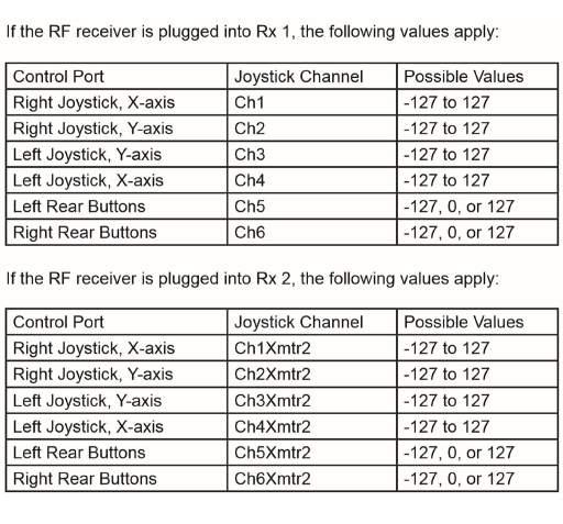
67 Using the Joystick Controller in ROBOTC


68 VEX Code Studio and the V5 Robot Brain
VEX Classroom Lab Kit to PLTW VEX POE Conversion Kit
 Published: 03/22/20 Picture Part Description Number 275-88 Rack Gearbox Bracket (2-pack): Combines with the VEX linear slides & Rack Gears to create a linear actuator. Quantity 276-096 Linear Slide (2-pack):
Motion. Table of Contents: Introduction to the Motion Subsystem 3.2. Concepts to Understand 3.8. Subsystem Interactions Motion.
 The Motion Subsystem of the robot is responsible for exactly that, motion. It includes both the motors that generate motion, and the wheels and gears that transfer and transform that motion into the desired
motion table of contents: squarebot assembly 3.2 concepts to understand 3.3 subsystems interfaces 3.21 motion subsystem inventory 3.
 The subsystem of the robot is responsible for exactly that,. It includes both the motors that generate, and the wheels and gears that transfer and transform that into the desired forms. With the structural
structure table of contents: squarebot chassis parts and assembly 2.2 concepts to understand 2.27 subsystems interfaces 2.37
 The structural subsystem of the robot is responsible for physical support. It holds everything in place, and is, in effect, the durable skeleton of the robot to which all the other subsystems are attached.
Working with VEX Parts
 VEX Robotics Design System VEX Classroom Lab Kit The VEX Robotics Design System is divided up into several different Subsystems: Structure Subsystem Motion Subsystem Power Subsystem Sensor Subsystem Logic
1x25 bar. 5x25 plate. 1x2x35 rail. 2x2x35 L. 3x3x35 L. 1x2x1x35 C. 1x3x1x35 C. 1x5x1x35 C
 STRUCTURE 1x25 bar 5x25 plate 45 degree gusset 90 degree flat gusset 1x2x25 rail 90 degree vertical gusset cross gusset 1x2x35 rail 2x2x35 L L gusset arc gusset 3x3x35 L hinge 90 degree corner gusset 1x2x1x35
How to Build with the Mindstorm Kit
 How to Build with the Mindstorm Kit There are many resources available Constructopedias Example Robots YouTube Etc. The best way to learn, is to do Remember rule #1: don't be afraid to fail New Rule: don't
CLAWBOT WITH SENSORS BUILDING INSTRUCTIONS
 CLAWBOT WITH SENSORS BUILDING INSTRUCTIONS USING THE VEX CORTEX Clawbot 1.0 1 1 Collect the parts and tools from the list below to attach the sensors: Materials Quantity Shaft, 4 Long 1 Shaft, 5 Long 2
LEGO Education WeDo 2.0 Toolbox
 LEGO Education WeDo 2.0 Toolbox WeDo 2.0 Table of Contents Program with WeDo 2.0 3-21 Build with WeDo 2.0 22-36 Program with WeDo 2.0 Programming is an important part of twenty-first century learning,
Simple Gears and Transmission
 Simple Gears and Transmission Simple Gears and Transmission page: of 4 How can transmissions be designed so that they provide the force, speed and direction required and how efficient will the design be?
Smart Spinner. Age 7+ Teacher s Notes. In collaboration with NASA
 Smart Spinner Age 7+ Teacher s Notes In collaboration with NASA LEGO and the LEGO logo are trademarks of the/sont des marques de commerce de/son marcas registradas de LEGO Group. 2012 The LEGO Group. 190912
Week 11. Module 5: EE100 Course Project Making your first robot
 Week 11 Module 5: EE100 Course Project Making your first robot Dr. Ing. Ahmad Kamal Nasir Office Hours: Room 9-245A Tuesday (1000-1100) Wednesday (1500-1600) Course Project: Wall-Follower Robot Week 1
index Page numbers shown in italic indicate figures. Numbers & Symbols
 index Page numbers shown in italic indicate figures. Numbers & Symbols 12T gear, 265 24T gear, 265 36T gear, 265 / (division operator), 332 % (modulo operator), 332 * (multiplication operator), 332 A accelerating
Teachers Resource: BaseBot Assembly
 Teachers Resource: BaseBot Assembly Overview: This document contains all the instructions for assembling the BaseBot. The diagram numbers correspond to the section of the REC curriculum in which the instructions
index changing a variable s value, Chime My Block, clearing the screen. See Display block CoastBack program, 54 44
 index A absolute value, 103, 159 adding labels to a displayed value, 108 109 adding a Sequence Beam to a Loop of Switch block, 223 228 algorithm, defined, 86 ambient light, measuring, 63 analyzing data,
BASIC MECHATRONICS ENGINEERING
 MBEYA UNIVERSITY OF SCIENCE AND TECHNOLOGY Lecture Summary on BASIC MECHATRONICS ENGINEERING NTA - 4 Mechatronics Engineering 2016 Page 1 INTRODUCTION TO MECHATRONICS Mechatronics is the field of study
VEX IQ Curriculum: Let s Get Started
 VEX IQ Curriculum: Let s Get Started Let s Get Started Student Handout Using VEX IQ Hardware The VEX IQ platform kits provide easy, fun, and accessible tools to teach and learn all four legs of STEM, no
Reliable Reach. Robotics Unit Lesson 4. Overview
 Robotics Unit Lesson 4 Reliable Reach Overview Robots are used not only to transport things across the ground, but also as automatic lifting devices. In the mountain rescue scenario, the mountaineers are
Welcome to the world of fischertechnik's ROBOTICS line 3 Some General Information 3. Component Explanations 4
 Welcome to the world of fischertechnik's ROBOTICS line 3 Some General Information 3 Electricity 3 Robots, Artificial Humans? 4 ROBOTICS, (Almost) Everything Automatic 4 Component Explanations 4 ROBOTICS
All levers are one of three types, usually called classes. The class of a lever depends on the relative position of the load, effort and fulcrum:
 Página 66 de 232 Mechanisms A mechanism is simply a device which takes an input motion and force, and outputs a different motion and force. The point of a mechanism is to make the job easier to do. The
System Integration of an Electronic Monitoring System in All-Terrain Vehicles
 System Integration of an Electronic Monitoring System in All-Terrain Vehicles Waylin Wing Central Michigan University, Mount Pleasant, MI 48858 Email: wing1wj@cmich.edu An electronic monitoring system
Chapter 7: DC Motors and Transmissions. 7.1: Basic Definitions and Concepts
 Chapter 7: DC Motors and Transmissions Electric motors are one of the most common types of actuators found in robotics. Using them effectively will allow your robot to take action based on the direction
Driver Driven. InputSpeed. Gears
 Gears Gears are toothed wheels designed to transmit rotary motion and power from one part of a mechanism to another. They are fitted to shafts with special devices called keys (or splines) that ensure
MECHANISMS. AUTHORS: Santiago Camblor y Pablo Rivas INDEX
 MECHANISMS AUTHORS: Santiago Camblor y Pablo Rivas INDEX 1 INTRODUCTION 2 LEVER 3 PULLEYS 4 BELT AND PULLEY SYSTEM 5 GEARS 6 GEARS WITH CHAIN 7 WORM GEAR 8 RACK AND PINION 9 SCREW AND NUT 10 CAM 11 ECCENTRIC
2018 KANSAS BEST BREAKOUT SESSIONS
 2018 KANSAS BEST BREAKOUT SESSIONS Tips for Building a Robot Bryan Jaax September 8, 2018 1 ST STEP: READ the RULES and Technical Data Package 2 FOLLOW AN ENGINEERING PROCESS Define the Problem Brainstorm:
Robotic Systems ECE 401RB Fall 2007
 The following notes are from: Robotic Systems ECE 401RB Fall 2007 Lecture 4: Actuators Part 1 Chapter 3, George A. Bekey, Autonomous Robots: From Biological Inspiration to Implementation and Control, The
Wheeled Mobile Robots
 Wheeled Mobile Robots Most popular locomotion mechanism Highly efficient on hard and flat ground. Simple mechanical implementation Balancing is not usually a problem. Three wheels are sufficient to guarantee
Deriving Consistency from LEGOs
 Deriving Consistency from LEGOs What we have learned in 6 years of FLL by Austin and Travis Schuh Objectives Basic Building Techniques How to Build Arms and Drive Trains Using Sensors How to Choose a Programming
The CMPE 118 Cockroach Robot Dept. of Computer Engineering, UCSC
 The CMPE 118 Cockroach Robot Dept. of Computer Engineering, UCSC Background: The CMPE-118 Cockroach robot is designed to be an accessible mobile platform to teach you basic state machine programming. This
ROBOTICS BUILDING BLOCKS
 ROBOTICS BUILDING BLOCKS 2 CURRICULUM MAP Page Title...Section Estimated Time (minutes) Robotics Building Blocks 0 2 Imaginations Coming Alive 5...Robots - Changing the World 5...Amazing Feat 5...Activity
Grade 8 Science. Unit 4: Systems in Action
 Grade 8 Science Unit 4: Systems in Action Machines That Turn Last class we looked at the idea of a boat winch, a wheel and axle used to get a boat out of the water, onto a trailer. You rotate the handle
TRUELINE LEVELING SYSTEM
 TRUELINE LEVELING SYSTEM Installation & Operation Guide VTL01K011 Valid Manufacturing Ltd. Advanced Technologies Simple Solutions Trueline Leveling System Installation & Operation Guide 1 TABLE OF CONTENTS
Lifting Mechanisms. Example 1: Two Stage Lift
 Lifting Mechanisms The primary scoring method for the 2018 game is to deposit fuel cubes into scoring zones. A manipulator fixed to your robot can deliver fuel cubes into ground level scoring zones, but
Mechanical Components and Programming. Ken Youssefi Introduction to Engineering E10 1
 Mechanical Components and Programming Ken Youssefi Introduction to Engineering E10 1 7.2 V, 3000 mah battery pack and charger Ken Youssefi Introduction to Engineering E10 2 Controller (Cortex) Motor and
Introduction. Kinematics and Dynamics of Machines. Involute profile. 7. Gears
 Introduction The kinematic function of gears is to transfer rotational motion from one shaft to another Kinematics and Dynamics of Machines 7. Gears Since these shafts may be parallel, perpendicular, or
Moments. It doesn t fall because of the presence of a counter balance weight on the right-hand side. The boom is therefore balanced.
 Moments The crane in the image below looks unstable, as though it should topple over. There appears to be too much of the boom on the left-hand side of the tower. It doesn t fall because of the presence
three different ways, so it is important to be aware of how flow is to be specified
 Flow-control valves Flow-control valves include simple s to sophisticated closed-loop electrohydraulic valves that automatically adjust to variations in pressure and temperature. The purpose of flow control
Table Of Contents. Motor Selection Guide Installation Instructions Operators 20-32
 Table Of Contents Motor Selection Guide 2-12 - Shades, Shutters and Doors - Retractable Awnings Installation Instructions 13-1 - Operator Adaptors - Operator Limit Adjustment - Wiring Considerations -
June 2011 Model Solution
 June 2011 Model Solution Bourne Grammar School 1a. An input transducer takes an input from the real world, and converts it into an electrical signal. A microphone, for instance. 1b. An output transducer
Engineering Design Process for BEST Robotics JANNE ACKERMAN COLLIN COUNTY (COCO) BEST & BEST OF TEXAS ROBOTICS
 BEST & BEST OF TEXAS ROBOTICS") Engineering Design Process for BEST Robotics JANNE ACKERMAN COLLIN COUNTY (COCO) BEST & BEST OF TEXAS ROBOTICS Agenda Getting Started Lessons Learned Design Process Engineering Mechanics 2 Save Time Complete
Engineering Design Process for BEST Robotics JANNE ACKERMAN COLLIN COUNTY (COCO) BEST & BEST OF TEXAS ROBOTICS Agenda Getting Started Lessons Learned Design Process Engineering Mechanics 2 Save Time Complete
IDL Dragonfly Manual
 2015 IDL-20003 Dragonfly Manual FIRMWARE VERSION 3.00 IRIS DYNAMICS LTD. IDL-20003 Manual IrisDynamics.com V1.00 December, 2015 IDL-20003 Manual IrisDynamics.com V1.00 December, 2015 Unpacking, Setup,
The electro-mechanical power steering with dual pinion
 Service Training Self-study programme 317 The electro-mechanical power steering with dual pinion Design and function The electro-mechanical power steering has many advantages over the hydraulic steering
Miscellaneous Measuring Devices
 Instrumentation 7 C H A P T E R Miscellaneous Measuring Devices Objectives After completing this chapter, you will be able to: Define terms associated with miscellaneous measuring devices: vibration rotational
30A BLDC ESC. Figure 1: 30A BLDC ESC
 30A BLDC ESC Figure 1: 30A BLDC ESC Introduction This is fully programmable 30A BLDC ESC with 5V, 3A BEC. Can drive motors with continuous 30Amp load current. It has sturdy construction with 2 separate
Slippage Detection and Traction Control System
 Slippage Detection and Traction Control System May 10, 2004 Sponsors Dr. Edwin Odom U of I Mechanical Engineering Department Advisors Dr. Jim Frenzel Dr. Richard Wall Team Members Nick Carter Kellee Korpi
Simple Gears and Transmission
 Simple Gears and Transmission Contents How can transmissions be designed so that they provide the force, speed and direction required and how efficient will the design be? Initial Problem Statement 2 Narrative
SuperQuest Salem Arms Best Practices
 SuperQuest Salem Arms Best Practices VEX Arm Designs Single 4-Bar 6-Bar 8-Bar Linear Slide Scissor Double Reverse 4-Bar Single Arms Arms These manipulators consist of a pivot point and at least 1 motor.
Robot Preparation for the VEX World Championship/ US Open. Lessons learned over the past 6 years by David Kelly 2013 VWC, Teacher of the Year
 Robot Preparation for the VEX World Championship/ US Open Lessons learned over the past 6 years by David Kelly 2013 VWC, Teacher of the Year Re-designing Re-designing your robot to a new concept yields
Pleo Booklet: Instructor
 Pleo Booklet: Instructor Introduction to Pleo What is Pleo? Pleo is a robotic dinosaur created by UGobe Life Forms. Pleo can interact with people and objects because she has her own senses and behaviors
MANTECH ELECTRONICS. Stepper Motors. Basics on Stepper Motors I. STEPPER MOTOR SYSTEMS OVERVIEW 2. STEPPING MOTORS
 MANTECH ELECTRONICS Stepper Motors Basics on Stepper Motors I. STEPPER MOTOR SYSTEMS OVERVIEW 2. STEPPING MOTORS TYPES OF STEPPING MOTORS 1. VARIABLE RELUCTANCE 2. PERMANENT MAGNET 3. HYBRID MOTOR WINDINGS
MEMS Sensors for automotive safety. Marc OSAJDA, NXP Semiconductors
 MEMS Sensors for automotive safety Marc OSAJDA, NXP Semiconductors AGENDA An incredible opportunity Vehicle Architecture (r)evolution MEMS & Sensors in automotive applications Global Mega Trends An incredible
Implementation Notes. Solar Group
 Implementation Notes Solar Group The Solar Array Hardware The solar array is made up of 42 panels each rated at 0.5V and 125mA in noon sunlight. Each individual cell contains a solder strip on the top
The H-MAC Heavy Metal Articulating Chassis Construction Guide
 The H-MAC Heavy Metal Articulating Chassis Construction Guide The Heavy Metal Chassis is constructed with two identical drive modules built using 10 mechanical sub-assemblies. The drive modules are integrated
Gear Ratios and Speed Background Material
 VEX Robotics Lab 3 How Do Gear Ratios Affect and Torque? Introduction In this investigation, students will learn the relationships between gear ratio, axle speed, and torque. Students will use the Vex
Unit 1 Introduction to VEX and Robotics
 Unit Overview Unit 1 Introduction to VEX and Robotics VEX lab kits bring robotics into the classroom, making it a fun and educational experience for all. In this introductory unit, you review the kit and
Squarebot Upgrade (2.0 to 3.0) Conversion Instructions (cont.)
 Conversion Instructions (cont.)") Squarebot Upgrade (2.0 to 3.0) Conversion Instructions 1 Collect and identify the parts from the list of materials below: materials qty Squarebot 2.0 1 8-32 hex screw x 1/4 16 8-32 hex screw x 1/2 10 6-32
Squarebot Upgrade (2.0 to 3.0) Conversion Instructions 1 Collect and identify the parts from the list of materials below: materials qty Squarebot 2.0 1 8-32 hex screw x 1/4 16 8-32 hex screw x 1/2 10 6-32
GARAGE DOOR OPENER OWNER S MANUAL S3/S4
 GARAGE DOOR OPENER OWNER S MANUAL S3/S4 Features! Locking door during power failure: If power failure occurs while the door is operating, the door can be released by pulling the clutch down, allowing
RR Concepts. The StationMaster can control DC trains or DCC equipped trains set to linear mode.
 Jan, 0 S RR Concepts M tation aster - 5 Train Controller - V software This manual contains detailed hookup and programming instructions for the StationMaster train controller available in a AMP or 0AMP
Azatrax MRX3 Grade Crossing Signal Controller Installation Guide
 Azatrax MRX3 Grade Crossing Signal Controller Installation Guide What it is: The MRX3 is a sophisticated controller that realistically operates model railroad / highway crossing signals. The MRX3 includes
Basic Electricity. Mike Koch Lead Mentor Muncie Delaware Robotics Team 1720 PhyXTGears. and Electronics. for FRC
 Basic Electricity and Electronics for FRC Mike Koch Lead Mentor Muncie Delaware Robotics Team 1720 PhyXTGears The Quick Tour The Analog World Basic Electricity The Digital World Digital Logic The Rest
Warning! Before continuing further, please ensure that you have NOT mounted the propellers on the MultiRotor.
 Mission Planner Setup ( optional, do not use if you have already completed the Dashboard set-up ) Warning! Before continuing further, please ensure that you have NOT mounted the propellers on the MultiRotor.
Installation and User Manual. with RAIN SENSOR.
 with RAIN SENSOR www.solarsmartopener.com Revision..0 TABLE OF CONTENTS Features In The Box Further Items Required Basic Operation Solar Panel and Operator Installation Operator Installation Solar Panel
TOUCH PLS TOUCHSCREEN PLS A NEW HORIZON IN PROGRAMMABLE LIMIT SWITCHES
 TOUCH PLS TOUCHSCREEN PLS A NEW HORIZON IN PROGRAMMABLE LIMIT SWITCHES Touchscreen PLS and Graphical Operator Interface in One Unit Five Screen Sizes Available: 5" Color, 6" Monochrome, 8" Color, 9" Monochrome
Robotic Systems ECE 401RB Fall 2006
 The following notes are from: Robotic Systems ECE 401RB Fall 2006 Lecture 8: Actuators Part 2 Chapter 19, G. McComb, and M. Predko, Robot Builder's Bonanza, Third Edition, Mc- Graw Hill, 2006. I. Gears
TIPS TO FINAL ASSEMBLY Radio installation. The Electronic speed control (ESC) and the receiver need to be mounted onto the chassis, using double sided
 and the receiver need to be mounted onto the chassis, using double sided") TIPS TO FINAL ASSEMBLY Radio installation. The Electronic speed control (ESC) and the receiver need to be mounted onto the chassis, using double sided tape (not supplied.) Mount the ESC first on the chassis
TIPS TO FINAL ASSEMBLY Radio installation. The Electronic speed control (ESC) and the receiver need to be mounted onto the chassis, using double sided tape (not supplied.) Mount the ESC first on the chassis
PerfectTilt RF Motorized Shutter User Manual
 PerfectTilt RF Motorized Shutter User Manual Pictured: PerfectTilt RF Solar with auxiliary solar panels and auxiliary battery pack INTRODUCTION The PerfectTilt RF motorization system features a remote
Module 1: Introduction to Drive Trains
 Introduction ÂÂ Basic Components of a Drive Train Operation of a Drive Train Working Applications Types of Drives Types of Gears Formula for Calculating Gear Ratio Determining Gear Rotation Introduction
NOS -36 Magic. An electronic timer for E-36 and F1S Class free flight model aircraft. January This document is for timer version 2.
 NOS -36 Magic An electronic timer for E-36 and F1S Class free flight model aircraft January 2017 This document is for timer version 2.0 Magic Timers Copyright Roger Morrell January 2017 January 2017 Page
ARDUINO 2WD SMART ROBOT CAR KIT
 EN ARDUINO 2WD SMART ROBOT CAR KIT P a g e 2 PARTS LIST Please make sure that the following pieces are included in your kit Component Quantity Remarks Arduino Sensor Shield v5.0 1 Align pins using needle
roving on the moon Leader Notes for Grades 6 12 The Challenge Prepare ahead of time Introduce the challenge (5 minutes)
") for Grades 6 12 roving on the moon Leader Notes The Challenge Build a rubber band-powered rover that can scramble across the room. In this challenge, kids follow the engineering design process to: (1)
for Grades 6 12 roving on the moon Leader Notes The Challenge Build a rubber band-powered rover that can scramble across the room. In this challenge, kids follow the engineering design process to: (1)
IR Receivers: These parts detect IR light reflected from objects such as walls and people. This is useful for navigation.
 Introduction: We are providing this document as a means of providing more enjoyment of the robot. Please keep in mind as you read through the drawings that any attempt at opening the robot could and most
Step Motor. Mechatronics Device Report Yisheng Zhang 04/02/03. What Is A Step Motor?
 Step Motor What is a Step Motor? How Do They Work? Basic Types: Variable Reluctance, Permanent Magnet, Hybrid Where Are They Used? How Are They Controlled? How To Select A Step Motor and Driver Types of
feature 10 the bimmer pub
 feature 10 the bimmer pub BMW E90 Steering Angle Sensor Diagnosis A pattern failure may indeed point you to a bad component, but when the part is expensive you want to be very sure it s the culprit before
Autonomously Controlled Front Loader Senior Project Proposal
 Autonomously Controlled Front Loader Senior Project Proposal by Steven Koopman and Jerred Peterson Submitted to: Dr. Schertz, Dr. Anakwa EE 451 Senior Capstone Project December 13, 2007 Project Summary:
Index. sequencing, 21, 26 starting off, 22 using, 28 code sequence, 28 custom pallete, 28
 Index A, B Blocks, 21 builder dialog, 24 code, DelaySequence, 25 editing, 26 delay sequence, 26 in robot, 27 icon builder, 25 manage and share, 37 broken blocks, 39 custom palette, 37 folder selection,
INTRODUCTION TO MECHATRONICS PRASHANT AMBADEKAR
 INTRODUCTION TO MECHATRONICS PRASHANT AMBADEKAR WHAT IS CONTROL? Control is the process of altering, manually or automatically, the performance of a system to a desired one. WHY CONTROL? Because systems
Technical Robustness and Quality
 Technical Robustness and Quality www.teamrush27.net Rock Solid Robot Page Title 1-4 Robustness In Concept And Fabrication 5 Creative Concepts For Tomorrow s Technology 6-8 Rock Solid Controls 9-10 Effectively
Timing is everything with internal combustion engines By: Bernie Thompson
 Timing is everything with internal combustion engines By: Bernie Thompson As one goes through life, it is said that timing is everything. In the case of the internal combustion engine, this could not be
V 2.0. Version 9 PC. Setup Guide. Revised:
 V 2.0 Version 9 PC Setup Guide Revised: 06-12-00 Digital 328 v2 and Cakewalk Version 9 PC Contents 1 Introduction 2 2 Configuring Cakewalk 4 3 328 Instrument Definition 6 4 328 Automation Setup 8 5 Automation
RB-Mel-03. SCITOS G5 Mobile Platform Complete Package
 RB-Mel-03 SCITOS G5 Mobile Platform Complete Package A professional mobile platform, combining the advatages of an industrial robot with the flexibility of a research robot. Comes with Laser Range Finder
Gears and Sprockets for Basic Robotics
 Gears and Sprockets for Basic Robotics Written by George Gillard Published: 24-May-2016 Introduction Gears and Sprockets are powerful tools in robotics. They can be used to make something spin or move
CENTROIDTM. AC Brushless Drive. Product Spec Sheet
 4 Axis, up to 2 KW motors Brake Output for each axis Overtemp and Overcurrent Protection All-software Configuration Self-cooled Fiber Optic Control CENTROIDTM AC Brushless Drive Product Spec Sheet AC Brushless
Bag 1. Bag 1. Center Pivot. Center Pivot
 8 00734 01901 5 Center Pivot Bag 1 3374 - Center Pivot Socket 4019 - Alum Pivot ball 3254-2-56 Button Head *Note - Sometimes it is helpful to slightly over-tighten the top clamp screws, then work the ball
GUIDE FOR BUILDING THE CLAWBOT
 GUIDE FOR BUILDING THE CLAWBOT NOTE: This kit requires other components which are not included in order to build a complete working robot. The primary additional required component is a compatible VEX
Linear Motion and Assembly Technologies Pneumatics Service. forces to the crankshaft s surface to reduce fatigue.
 Electric Drives and Controls Hydraulics Linear Motion and Assembly Technologies Pneumatics Service profile Drive & Control Roll with the Changes: Ingersoll Crankshaft Rolling Machine Uses Integrated Axis
Unit 2: Electricity and Energy Resources
 8 8 Table of Contents Unit 2: Electricity and Energy Resources Chapter 8: Magnetism and Its Uses 8.1: Magnetism 8.2: Electricity and Magnetism 8.3: Producing Electric Current 8.1 Magnets More than 2,000
PORTAGAUGE 4 USER MANUAL
 PORTAGAUGE 4 USER MANUAL Contents 1. Introduction and Key Features 1.1 What does the Portagauge do? 1.2 The Portagauge 4 1.21 The Portagauge 4 Unit and Measuring Screen 1.22 The Portagauge 4 Definition
3/31/2016. Unit 2: Electricity and Energy Resources. Magnets. Magnets. Magnetic Force. Magnetic Field. Chapter 8: Magnetism and Its Uses
 8 8 Table of Contents Unit 2: Electricity and Energy Resources Chapter 8: and Its Uses : : Electricity and : Magnets More than 2,000 years ago Greeks discovered deposits of a mineral that was a natural
Project Proposal for Autonomous Vehicle
 Project Proposal for Autonomous Vehicle Group Members: Ramona Cone Erin Cundiff Project Advisors: Dr. Huggins Dr. Irwin Mr. Schmidt 12/12/02 Project Summary The autonomous vehicle uses an EMAC based system
Overview of operation modes
 Overview of operation modes There are three main operation modes available. Any of the modes can be selected at any time. The three main modes are: manual, automatic and mappable modes 1 to 4. The MapDCCD
10 STEM Electric Car Assessment Task Name
 10 STEM Electric Car Assessment Task Name Step 1 identify parts. Collect a piece of corflute and an electric car kit. Open your electic car kit components. We will be using all of the pieces, except the
Compound Gears Laboratory - Part 2
 Compound Gears Laboratory - Part 2 Names: Date: About this Laboratory In this laboratory, you will explore compound gear trains, gear ratios, and how the number of teeth on a drive and driven gear affect
Roehrig Engineering, Inc.
 Roehrig Engineering, Inc. Home Contact Us Roehrig News New Products Products Software Downloads Technical Info Forums What Is a Shock Dynamometer? by Paul Haney, Sept. 9, 2004 Racers are beginning to realize
RTOS-CAR USING ARM PROCESSOR
 Int. J. Chem. Sci.: 14(S3), 2016, 906-910 ISSN 0972-768X www.sadgurupublications.com RTOS-CAR USING ARM PROCESSOR R. PATHAMUTHU *, MUHAMMED SADATH ALI, RAHIL and V. RUBIN ECE Department, Aarupadai Veedu
(FPGA) based design for minimizing petrol spill from the pipe lines during sabotage
 based design for minimizing petrol spill from the pipe lines during sabotage") IOSR Journal of Engineering (IOSRJEN) ISSN (e): 2250-3021, ISSN (p): 2278-8719 Vol. 05, Issue 01 (January. 2015), V3 PP 26-30 www.iosrjen.org (FPGA) based design for minimizing petrol spill from the pipe
IOSR Journal of Engineering (IOSRJEN) ISSN (e): 2250-3021, ISSN (p): 2278-8719 Vol. 05, Issue 01 (January. 2015), V3 PP 26-30 www.iosrjen.org (FPGA) based design for minimizing petrol spill from the pipe
NEW CAR TIPS. Teaching Guidelines
 NEW CAR TIPS Teaching Guidelines Subject: Algebra Topics: Patterns and Functions Grades: 7-12 Concepts: Independent and dependent variables Slope Direct variation (optional) Knowledge and Skills: Can relate
Table of Contents. Executive Summary...4. Introduction Integrated System...6. Mobile Platform...7. Actuation...8. Sensors...9. Behaviors...
 TaleGator Nyal Jennings 4/22/13 University of Florida Email: Magicman01@ufl.edu TAs: Ryan Chilton Josh Weaver Instructors: Dr. A. Antonio Arroyo Dr. Eric M. Schwartz Table of Contents Abstract...3 Executive
Product Manual. 42BYGH40(M)-160-4A NEMA 17 Bipolar 5.18:1. Planetary Gearbox Stepper
-160-4A NEMA 17 Bipolar 5.18:1. Planetary Gearbox Stepper") Product Manual 42BYGH40(M)-160-4A NEMA 17 Bipolar 5.18:1 Planetary Gearbox Stepper Phidgets - Product Manual 42BYGH40(M)-160-4A NEMA 17 Bipolar 5.18:1 Planetary Gearbox Stepper Phidgets Inc. 2011 Contents
Product Manual 42BYGH40(M)-160-4A NEMA 17 Bipolar 5.18:1 Planetary Gearbox Stepper Phidgets - Product Manual 42BYGH40(M)-160-4A NEMA 17 Bipolar 5.18:1 Planetary Gearbox Stepper Phidgets Inc. 2011 Contents
Revolver Reference Manual
 creative conners, inc. Revolver Reference Manual Version 1.1 (November 2012) Copyright 2012. Creative Conners, Inc. All rights reserved. Contents 1 Getting Started... 2 1.1 A word about safety... 2 1.2
MECHATRONICS LAB MANUAL
 MECHATRONICS LAB MANUAL T.E.(Mechanical) Sem-VI Department of Mechanical Engineering SIESGST, Nerul, Navi Mumbai LIST OF EXPERIMENTS Expt. No. Title Page No. 1. Study of basic principles of sensing and