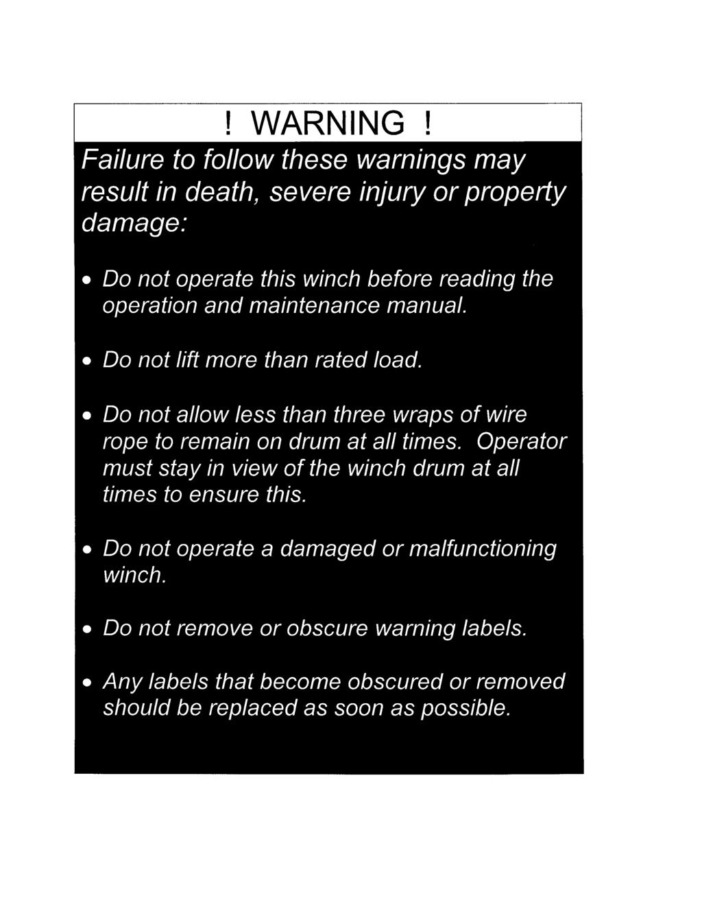
INVADER MODEL K5UR100ML UTILITY AND MANLIFTER AIR WINCH. Warning! Review WINCH OPERATING PRACTICES Prior to use.
|
|
|
- Polly Lamb
- 5 years ago
- Views:
Transcription
 and any other applicable safety codes and regulations.")
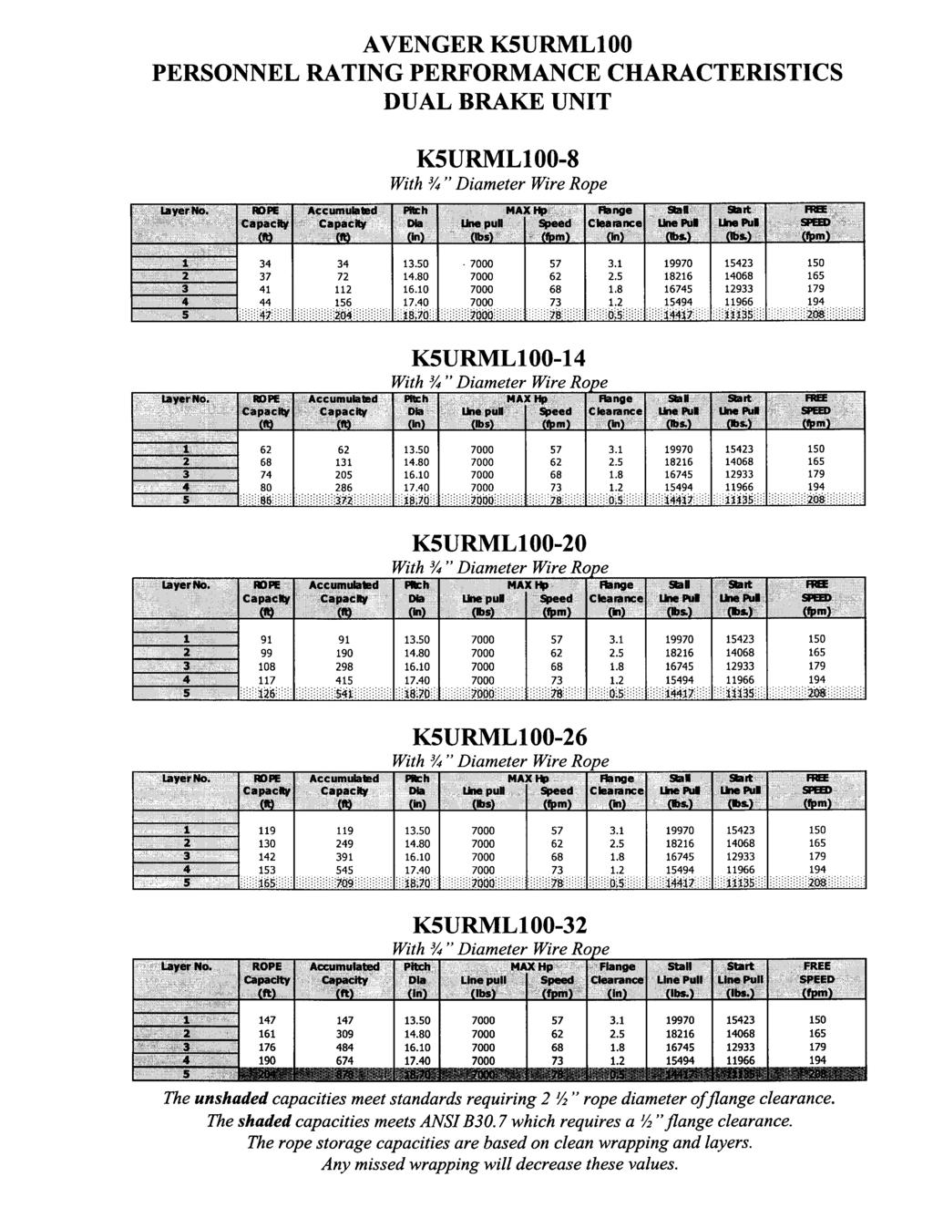
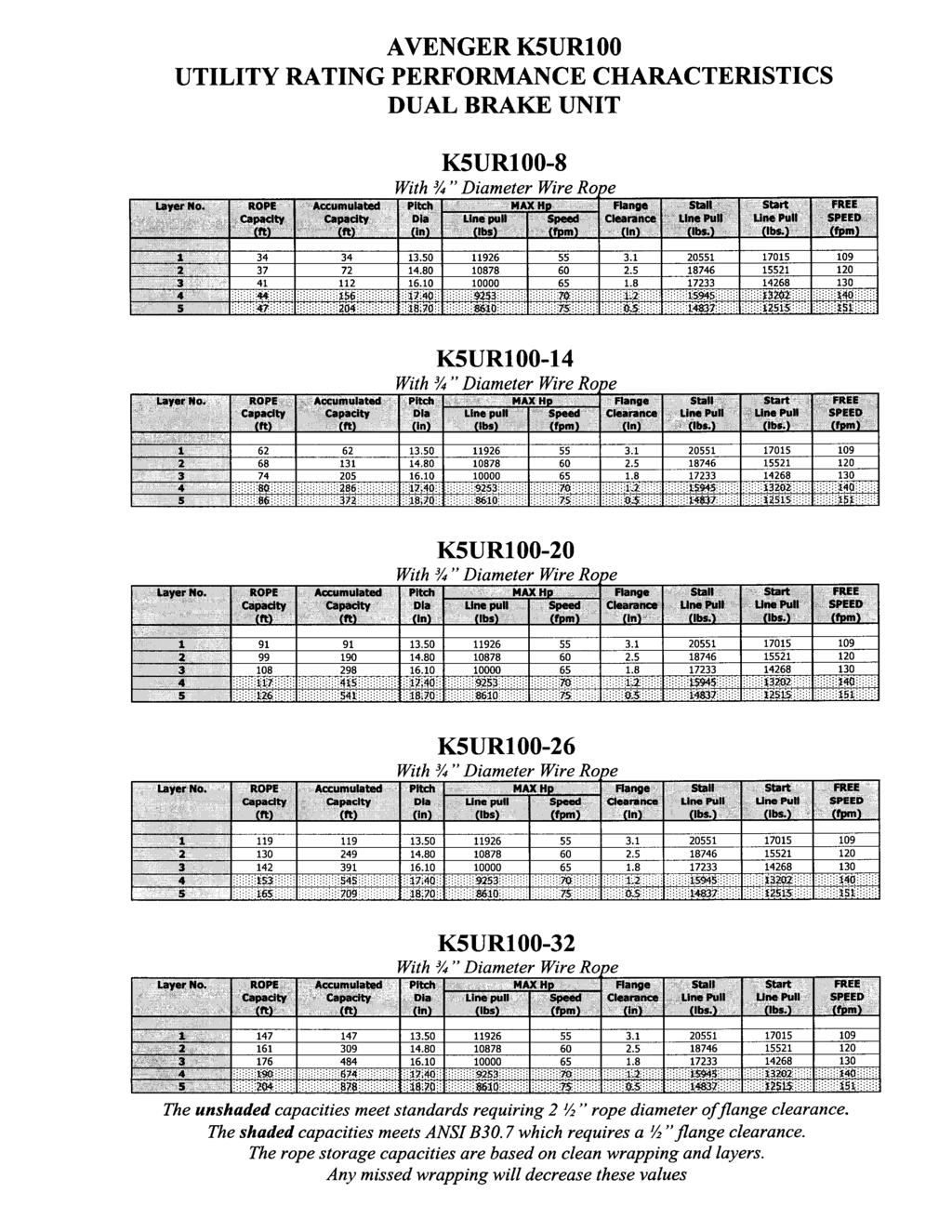
1 Instructions, Parts and Maintenance Manual INVADER MODEL K5UR100ML UTILITY AND MANLIFTER AIR WINCH Warning! Review WINCH OPERATING PRACTICES Prior to use. Always operate, inspect and maintain this winch in accordance with American National Standards Institute Safety Code (ANSI B30.7) and any other applicable safety codes and regulations. This winch is only a component of the lifting system, which must be designed by qualified personnel CHRISMAN HOUSTON, TEXAS (281) FAX: (281) or (888)
2
3
4
5 Table of Contents Continued 4.0 Operating Instructions 4.1 Operator Start Up 4.2 Shutdown 5.0 Preventive Maintenance 5.1 Introduction 5.2 Maintenance Plan Lubrication Schedule Cleaning Cable and Hoses In Field Load Brake Adjustment Procedure 6.0 Component Removal/Replacement Appendices Personnel Rating Performance Characteristics Utility Rating Performance Characteristics RAM Winch & Hoist Parts Information Avenger 100 General Arrangement Drawing Avenger 100 Drum Guard Drawing Avenger 100 Exploded View Figures 1 through 5 Avenger 100 Winch Assembly Bill of Material Avenger 100 Manual Brake Bill of Material Avenger 100 Auto Brake Bill of Material Avenger 100 Manual & Auto Brake Bill of Material Avenger 100 Recommended Spares K5U Air Motor Parts Listing K5U Air Motor Assembly Illustration Power Wheel Service Manual Model 9
6
7
8
9
10
11
12
13
14
15
16
17
18
19 1.0 General Information 1.1 User Responsibility and Safety Precautions MODEL IDENTIFICATION The exact model number of your winch is located on the RAM winch nameplate permanently mounted on the winch. The RAM model number identification chart located on the inside of the front cover of this manual explains the model number codes for the various features provided on your winch. This equipment will perform in conformity with the description thereof, contained in this manual, its accompanying labels and/or inserts when it is installed, operated, maintained and repaired according to the instructions provided. This equipment must be checked periodically. Deficient equipment should not be used. Parts that are broken, missing, plainly worn, distorted or contaminated should be replaced immediately. Should such repair or replacement become necessary, we recommend that a telephone or written request for service be made to RAM Winch & Hoist. This equipment or any of its parts should not be altered without prior written approval of RAM Winch & Hoist. The user of this equipment shall have the sole responsibility for any malfunction that results from improper use, faulty maintenance, damage, improper repairs or alterations made by anyone other than RAM Winch & Hoist. 1.2 Introduction Purpose The purpose of this manual is to provide operating instructions and maintenance procedures for your RAM Winch & Hoist Air Winch Model Number, Serial Number and Options This manual covers the winch built by RAM Winch & Hoist for your particular unit. The model and serial numbers are listed on the nameplate attached to the unit Warranty See standard warranty certificate. 1.3 Equipment Description Capabilities and Limitations The winch is an air, planetary driven cable-handling unit with manual release and auto release band brakes, designed for use in the marine or industrial environment.
20
21
22
23
24
25
26
27
28
29
30
31
32
33
34
35
36
37
38
39
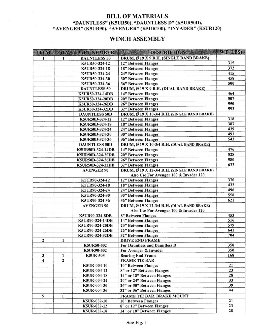
40 BILL OF MATERIALS DAUNTLESS (K5UR50), DAUNTLESS D (K5UR50D), AVENGER (K5UR90), AVENGER (K5UR100), INVADER (K5UR120) WINCH ASSEMBLY CONTINUED ITEM QTY PART NUMBER DESCRIPTION WT (LBS) K5UR or 24 Between Flanges 33 K5UR or 30 Between Flanges 39 K5UR or 36 Between Flanges HUR-010 Tie Bar Flange Bolt HUR-018 Tie Bar O-Ring, Small HUR-222 Tie Bar O-Ring, Large GEARBOX ASSEMBLY K5UR50-A353 For Dauntless 105 K5UR50D-A353 For Dauntless D 105 K5UR90-A353 For Avenger K5UR100-A353 For Avenger K5UR120-A353 For Invader DRUM/GEARBOX HEX BOLT K5UR For Dauntless & Dauntless D 2 K5UR For Avenger & Invader LOCKWASHER K5UR50-TAB For Dauntless & Dauntless D 0 K5UR90-TAB For Avenger & Invader FRAME/GEARBOX HEX BOLT K5UR For Dauntless & Dauntless D 2 K5UR For Avenger & Invader AG78056 WASHER INTERFACE SHAFT K5UR-506 For Dauntless/Dauntless D & Avenger 3.5 K5UR For Invader K5UR-016 Shaft Oil Seal KD5-A501 Air Motor W/Controls KX-36 Frame/Motor Hex Bolt A-67 Lockwasher KU-895 Bearing, Crank Motor End KK5UM-545 Valve Chest 21 1 KU-546A Valve Chest Cover 22 4 KU-548 Hex Head Capscrew D Lockwasher K5UR-466 Bearing K5UR-508 Bearing End Cover D Hex Head Capscrew D Lockwasher HUR-165 Oil Hex Plug HUR-381 Rope Locking Wedge DRUM/GEARBOX GASKET HUR-594 For Dauntless & Dauntless D 0 HUR-594 For Avenger & Invader FRAME/GEARBOX GASKET HUR-593 For Dauntless & Dauntless D 0 K5UR-593 For Avenger & Invader HUR-592 Frame/Motor Gasket HUR-595 Bearing End Cover Gasket 0 See Fig. 1
41
42
43
44
45
46
47
48
49
50
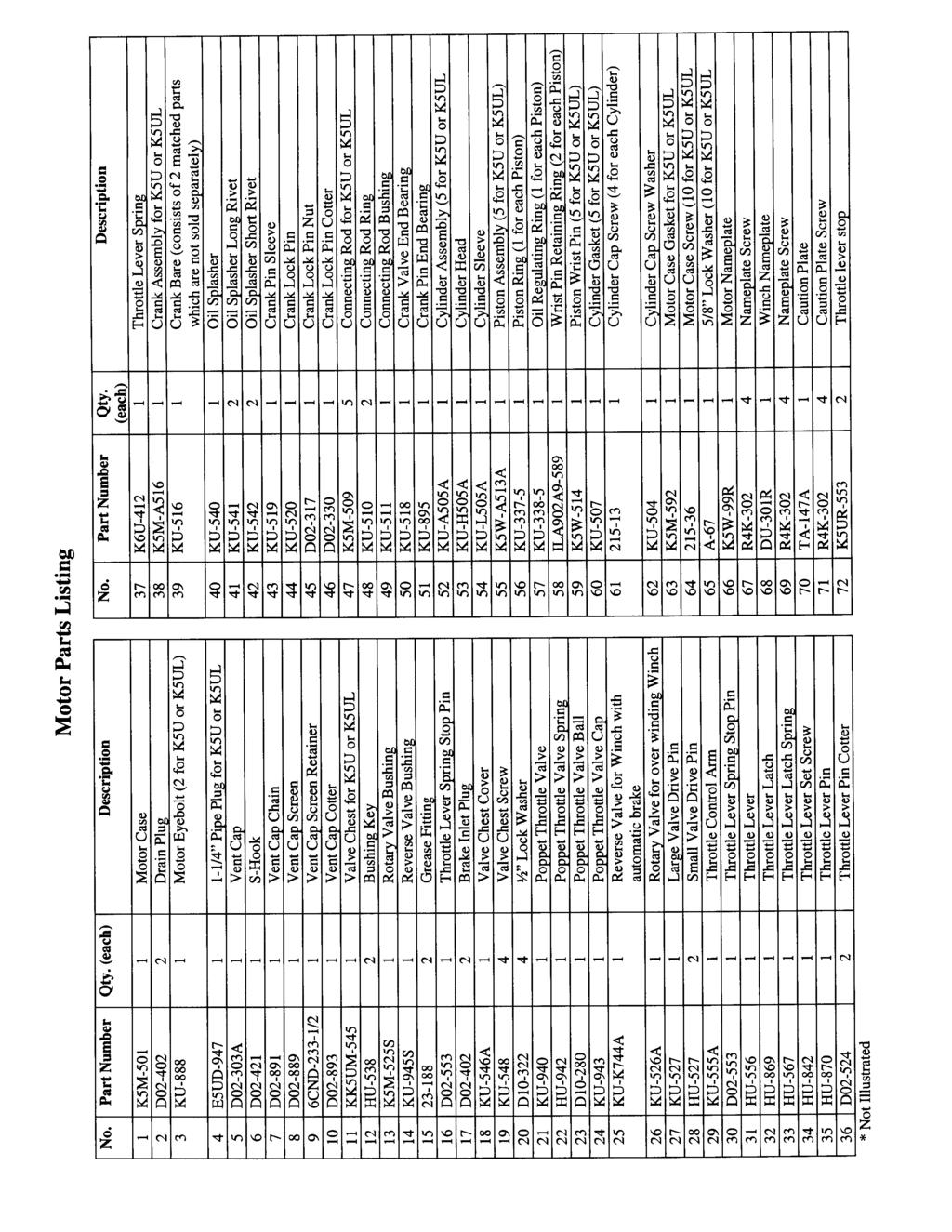
51 RECOMMENDED SPARES DAUNTLESS (K5UR50), DAUNTLESS D (K5UR50D), AVENGER (K5UR90), AVENGER (K5UR100), INVADER (K5UR120) QTY PART NO DESCRIPTION 1 HU-942 Poppet Throttle Valve Spring 1 KU-527 Large Valve Drive Pin 2 HU-527 Small Valve Drive Pin 1 HU-556 Throttle Lever 1 HU-567 Throttle Lever Latch Spring 1 KU-519 Crank Pin Sleeve 1 KU-518 Crank Valve End Bearing 1 KU-895 Crank Pin End Bearing 1 KU Piston Ring Set 1 KU Oil Regulating Ring Set 5 KU-507 Cylinder Gasket 1 K5M-592 Motor Case Gasket 1 K5UR-466 Drum Bearing 1 K5UR-508 End Cover Bearing 2 HUR-162 Clevis Pin 1 HUR-720 Air Cylinder 1 HUR-726 Compressor Spring 1 HUR-715 Brake Handle 1 KU-940 Poppet Throttle Valve 1 KU-943 Poppet Throttle Valve Cap 1 HU-870 Throttle Lever Pin 1 K6U-412 Throttle Lever Spring Recommended Spares for two (2) Year Foreign Operation FOB: Houston, Texas Terms of Payment: Net 30 Days
52
53
54
55 RAM P/N AH04414R Double Reduction Wheel Drive SERVICE MANUAL
56 Power Wheel Service Manual Model 9 Double Reduction Wheel Drives AUBURN, INDIANA U.S.A. PHONE: (219) FAX: (219) OPTIONAL
57 DISASSEMBLY OF POWER WHEEL Refer to Parts Illustration STEP 1 Slide the coupling (1) from splines on input shaft (2). STEP 2 Position the assembly upright on face of spindle (3). STEP 3 Remove the disengage cover (30) if necessary. STEP 4 Remove twenty-four bolts (26) and flat washers (27) and the large cover (25) from the unit. The thrust washer (22) and the disengage plunger (23) usually remain attached to the large cover (25) when it is removed. Remove thrust washer (22), disengage plunger (23) and O ring (24) from the large cover (25). STEP 5 Remove primary sun gear (21) from end of input shaft (2). STEP 6 Remove the primary carrier assembly (20). STEP 7 Remove the secondary carrier assembly (19). It may be necessary to remove the ring gear (18) first, if difficulty is encountered removing the carrier. STEP 8 Remove the input shaft (2) from spindle (3). Remove the retaining rings (15), washer (16), and disengage spring (17) from input shaft (2) only if replacement is required. STEP 9 If not previously removed (see step 7) remove ring gear (18) from hub (9). It may be necessary to strike ring gear (18) with a rubber mallet to loosen from hub (9). STEP 10 One tab of lock washer (13) will be engaged in the slot of bearing nut (14); bend back to release. Remove the bearing nut (14), lock washer (13) and thrust washer (12). Note: A special locknut wrench, 593RR, required for the removal of the bearing locknut. Contact RAM Winch & Hoist for procurement of wrench and other service tools. STEP 11 Bolt spindle drive tool, 598FF, to hub (9). Drive spindle (3) from hub (9) by turning bolt in center of spindle drive tool. Care should be taken to avoid damaging splines and threads on spindle. Note: Bearing cone (11) has been designed with a press fit with respect to spindle (3). Considerable force will be required to remove cone from spindle. STEP 12 Remove the boot seal (4) and oil seal (5) and bearing cones (6 & 11) from hub (9). Inspect bearing cups (7 & 10) in position and remove only if replacement is required.
58 Power Wheel Service Manual Model 9 Double Reduction Wheel Drives AUBURN, INDIANA U.S.A. PHONE: (219) FAX: (219) OPTIONAL
59 ASSEMBLY OF POWER WHEEL STEP 1 Press new bearing cups (7 & 10) in each side of the hub (9). It is recommended that bearing cups (7 & 10) and cones (6 & 12) be replaced in sets. STEP 2 Assemble bearing cone (6) into cup (7) at seal end of hub (9) and press a new seal (5) into hub (9). Install boot seal (4) on hub (9) if unit is so equipped. STEP 3 Position spindle (3) upright on bench. Lubricate lips of seal (4) and (5) and lower hub (9) onto spindle (3). Hub (9) should be centered as it is lowered over spindle (3) to prevent seal damage. STEP 4 Assemble bearing cone (11) over spindle (3). Press bearing cone (11) over spindle bearing journal using press and cylindrical bearing cone driver 598F. Pressure bearing cone (11) down until rollers just touch cup (10). Take care to avoid pressuring cone (11) too far. Note: If a press is not available, place tool 598F over splined end of spindle (3) on the edge of bearing cone (11) and drive into place with hammer or mallet. If this method is used, care must be taken to avoid damage to bearing cone and spindle. STEP 5 Install thrust washer (12) and bearing nut (14). DO NOT install lock washer (13) at this time. STEP 6 Place spindle drive tool, 598F, over spindle (3) and bolt or pin to hub (9). STEP 7 Check initial rolling torque by installing a lb.-in. torque wrench (arm or dial type) on center nut of spindle drive tool and turning hub (9) slowly and steadily with the torque wrench. Note mean torque. An initial bearing torque of greater than 52-lb. in. with boot seal installed or 48 lb. in. without boot seal means that the cone (11) was pressed on too tightly in step 4. In this case, back off bearing cone (11) by pressing spindle (3) out of cone (11) until initial preload is relieved. See step 11 of disassembly procedure. STEP 8 Torque bearing nut (14) with bearing nut wrench 593RR until a bearing rolling torque of lb. in., with a boot seal installed, or lb. in., without a boot seal, is reached. This may require several trials of pressing the cone (11) by torquing the nut (14) and then checking the rolling torque. Rotate hub (9) by hand as nut is being tightened in order to seat bearings. Note: Up to 250 lb. ft. of torque may have to be applied to bearing nut (14) in order to press cone (11) into position. STEP 9 Remove bearing nut (14) and install lock washer (13). Replace bearing nut (14). STEP 10 Re-torque bearing nut (14) to 65-75lb. ft. ( Nm).
60 Power Wheel Service Manual Model 9 Double Reduction Wheel Drives AUBURN, INDIANA U.S.A. PHONE: (219) FAX: (219) OPTIONAL
61 STEP 11 Secure bearing nut (14) by bending a lock washer (13) tab into one of four bearing nut slots. If no tab aligns with a slot, the nut may be tightened until one of the slots aligns with a lock washer tab. STEP 12 Assemble a washer (16), spring (17), a second washer (16), and a retaining ring (15) in the middle grooves of input shaft (2). Install a second retaining ring (15) in groove near small end of input shaft (2). STEP 13 Assemble the splined end of the input shaft (2) down into spindle (3). STEP 14 Assemble the secondary carrier assembly (19) to spindle (3) at splines. STEP 15 Clean mating surfaces and apply a bead of silicone sealant to face of hub (9) that mates with ring gear (18). See instructions on sealant package. Assemble ring gear (18) to hub (9) being careful to align bolt holes. STEP 16 Assemble the primary carrier assembly (20) into the ring gear (18). It will be necessary to rotate carrier to align secondary sun gear {part of primary carrier assembly (20)} with planet gear teeth in secondary carrier assembly (19). Assemble primary sun gear (21) over input shaft (2). Rotate primary sun gear (21) to align input shaft (2) to gear splines and gear teeth in primary carrier assembly (20). STEP 17 Lubricate O ring (24) and assemble in groove inside cover hole, push disengage plunger (23) into cover (25) with pointed end facing inside of unit. STEP 18 Assemble the thrust washer (22) with tangs engaged with cover (25). NOTE: A small amount of grease applied to the back side of thrust washer (22) will hold washer in place. Apply a bead of silicone sealant to end of face of ring gear (18). Assemble cover (25) aligning holes of cover and ring gear. Assemble the twentyfour 3/8-16 x 6-1/2 inch grade 8 bolts (26) and flat washers (27). Torque bolts to lb.-ft. (61-67 Nm). STEP 19 Assemble the disengage cover (30) with dimpled center protruding out if wheel is to be used to drive the vehicle. Assemble and torque the two 5/16-18 x 1/2 inch bolts (31). Torque bolts to lb.-ft. (13-27 Nm). STEP 20 Invert the Power Wheel assembly and assemble the coupling (1) with counter bore out to the input shaft (2) STEP 21 After motor is assembled to drive or drive is sealed at spindle, fill with lubricant to proper level and replace all plugs. Note: When installing a hydraulic motor to the Power Wheel drive it is necessary to place an O ring or gasket between the motor and the planetary drive. O ring sizes: SAE A 2-042, SAE B 2-155, SAE C
62
63 CARRIER ASSEMBLIES It is recommended that the primary and secondary carrier assemblies (18 & 19) be serviced entirely to protect the integrity of the Power Wheel drive. LUBRICATION RECOMMENDATIONS IMPORTANT: POWER WHEEL PLANETARY DRIVES ARE SHIPPED WITHOUT LUBRICANT AND MUST BE FILLED TO THE PROPER LEVEL PRIOR TO START UP. Observe lubrication recommendations given by the original equipment manufacturer. When specific recommendations are not available, use mild extreme pressure lubricant API-GL-5, No. 80 or 90 when filling the Power Wheel under normal temperature ranges between F (-18 to 49 C). Power Wheel is to be half full of oil when unit is mounted level and horizontal. Use drain and fill plugs located in cover and ring gear. Oil is to be changed after first 50 hours of operation with subsequent changes every 1000 hours or yearly, which ever comes first. If unit is to be operated vertically, if ambient conditions are outside the specified range, or if the oil temperature exceeds 200 F (93 C) contact RAM Winch & Hoist for oil and level recommendations. STORAGE A protective film is applied to the Power Wheel at the factory to prevent rust during shipment. Additional protection may be required if the Power Wheel is to be stored for an extended period of time. SEALING COMPOUND Silastic RTV732 sealer and General Electric Silimate RTV No or RTV No are currently recommended for sealing gasket surfaces. Sealant should be applied in continuous bead, which should be centered on the surface to be sealed but should move to the inside of the hole at each bolt hole location. For service requirements order RAM Winch & Hoist part number SPECIFICATIONS Maximum intermittent output torque...130,000 lb. In. (14,690 Nm) Maximum input speed...5,000 RPM Oil capacity...57 oz (1,685 ml)
64 Power Wheel Service Manual Model 9 Double Reduction Wheel Drives AUBURN, INDIANA U.S.A. PHONE: (219) FAX: (219) OPTIONAL
65 PARTS LISTING Refer to Parts Illustration Drawing for Item Numbers Item No. Used Item No.Used No. Description in Ass y. No. Description in Ass y. 1 Coupling 1 18 Ring Gear 1 2 Input Shaft 1 19 Secondary Carrier Assembly 1 3 Spindle 1 20 Primary Carrier Assembly 1 4 Boot Seal Primary Sun Gear 1 5 Oil Seal Thrust Washer 1 6 Bearing Cone Disengage Plunger 1 7 Bearing Cup O Ring Wheel Bolt Large Cover 1 9 Hub 1 26 Hex Head Bolt (Grade 8) Bearing Cup Flat Washer Bearing Cone Magnetic Plug Thrust Washer Pipe Plug 1 13 Lock Washer Disengage Cover Bearing Nut 2 31 Hex Head Bolt Retaining Ring 2 32 Quick Disconnect Gasket 1 16 Washer 1 33 Quick Disconnect Assembly 2 17 Disengage Spring Hex Head Bolt 2 Contact RAM Winch & Hoist at (281) with model number, item number and description to obtain the appropriate parts. Refer to parts list for the specific item numbers and quantities. Model 9 Power Wheel Service Kits Part No. Description Included Items 593RR Bearing Locknut Tool Not Shown 598F Bearing Cone Driver Not Shown 598FF Spindle/Shaft Drive Tool Not Shown
66
67
68
69
70

71
72
73
74
75 RAM P/N LB80045R LUBRICATOR Specifications Proof Pressure psig (Mpa) 220 (1.5) Max. Operating Pressure psig (Mpa) 145 (1) Operating Temperature Range 40 ~ 140 (5 ~ 60 C) Recommended Lubricant Turbine Oil #1 (ISO VG32) Pipe Size 1 ½ NPT Oil Capacity (cm3) 500 Flow Rate /n/min 12500
76
77
 Proof Pressure psig (Mpa) 220 (1.5) Max. Operating Pressure psig (Mpa) 150 (1.")
78 RAM P/N LB80040R FILTER Specifications Pipe Size 1 1/4 Net Bowl Capacity oz. (cm 3 ) 6.1 (180) Weight lbs. (kgf) 6.94 (3.15) Proof Pressure psig (Mpa) 220 (1.5) Max. Operating Pressure psig (Mpa) 150 (1.0) Operating Temperature Range 23 ~ 140 F (-5 ~ 60 C) Filtration 40 µm Flow Characteristics
79
80
81
 220 (1.5) Max. Operating Pressure psig (Mpa) 150 (1.")


82 RAM P/N LB80050 REGULATOR SPECIFICATIONS Port Size 1 ½ Proof Pressure psig (Mpa) 220 (1.5) Max. Operating Pressure psig (Mpa) 150 (1.0) Temperature 23 ~ 140 (-5 ~ 60C Pressure Regulating Range psig (Mpa) 7 ~ 120 (0.05 ~ 0.83) Body AC2A-F Bonnet ADC Chamber AC2A-F Valve Guide AC2A-F Weight lbs (kgf) 5.51 (2.5) FLOW CHARACTERISTICS Conditions: Supply Pressure 100 psig PRESSURE CHARACTERISTICS Supply Pressure 100 psig Secondary Pressure 30 psig (0.2 Mpa) Flow 0.7 SCFM (20l/min)

83 No. Name Material Part No. 5 Exhaust Valve Assembly A 6 Main Valve Diaphragm Assembly A 7 Valve Assembly A 8 Regulating Spring SWPB Valve Spring SUS Pilot Diaphragm A Dimensions A B C D E F (242) (89) (140) (113) 6.30 (160) 0.39 (10)
84
85
86
87
88 POWER WHEEL Service Manual RAM Winch & Hoist
RAM P/N AH04415R Double Reduction Wheel Drive SERVICE MANUAL
 RAM P/N AH04415R Double Reduction Wheel Drive SERVICE MANUAL Power Wheel Service Manual Model 7 Double Reduction Wheel Drives AUBURN, INDIANA 46706-3499 U.S.A. PHONE: (219) 925-3200 FAX: (219) 925-4725
SPIT TFIRE AIR WARNING! Review
 INSTRUCTIONS, PARTS AND MAINTENANCE MANUAL SPIT TFIRE H5UR50-18MX1 UTILITY AIR WINCH WARNING! Review WINCH OPERATING PRACTICES prior to use. Always operate, inspect and maintain this winch in accordance
AIR WINCH MODEL HU40 / HUL40
 Instructions, Parts and Maintenance AIR WINCH MODEL HU40 / HUL40 14603 CHRISMAN HOUSTON, TEXAS 77039 (281) 999-8665 FAX: (281) 999-8666 or (888) 726-5438 Warning Tags Safety Guidelines Winch Operating
AIR WINCH MODEL K6U. Warning! Review WINCH OPERATING PRACTICES Prior to use.
 Instructions, Parts and Maintenance Manual AIR WINCH MODEL K6U Warning! Review WINCH OPERATING PRACTICES Prior to use. Always operate, inspect and maintain this winch in accordance with American National
AIR WINCH MODEL K5U & K5UL. Warning! Review WINCH OPERATING PRACTICES Prior to use.
 Instructions, Parts and Maintenance Manual AIR WINCH MODEL K5U & K5UL Warning! Review WINCH OPERATING PRACTICES Prior to use. Always operate, inspect and maintain this winch in accordance with American
CHAPTER 15 WINCH MAINTENANCE. This chapter contains maintenance instructions for disassembly and repair of winch components at the Direct
 CHAPTER 15 WINCH MAINTENANCE This chapter contains maintenance instructions for disassembly and repair of winch components at the Direct 15-1. INTRODUCTION Support maintenance level. Some subassemblies
Service Manual. Example Part Number. Motor Supplier. Motor Number. Model. Bail Boss. Ratio. Shaft
 Service Manual 50 Series Digger models Example Part Number 50 05 f 54 Model Ratio Shaft Bail Boss Motor Supplier Motor Number This service manual is effective: S/N: 58670 to current date: 9-003 to CURRENT
Torque-Hub Planetary Final Drive S12A1 & 2 Series Service Manual
 Torque-Hub Planetary Final Drive S12A1 & 2 Series Service Manual Rev 8/30/13 1 While every precaution has been taken in the preparation of this document, Fairfield Manufacturing Co. Inc. assumes no liability
3.2 DRIVE TORQUE HUB. Roll, Leak and Brake Testing SECTION 3 - CHASSIS & TURNTABLE. 3-2 JLG Lift
 3.2 DRIVE TORQUE HUB Roll, Leak and Brake Testing 10 LUG PATTERN Torque-Hub units should always be roll and leak tested before disassembly and after assembly to make sure that the unit's gears, bearings
1984 Dodge W250 PICKUP
 1984 Dodge W250 PICKUP Submodel: Engine Type: V8 Liters: 5.2 Fuel Delivery: CARB Fuel: GAS Dana 44 MODELS THROUGH 1984 2. Raise and safely support the vehicle, then remove the wheel hub and bearings as
Instructions, Parts and Maintenance Manual AIR WINCH MODEL K6UL K6UL35WF TRANSOCEAN OFFSHORE P.O. GLOBE RAM Job# RS8839 S/N???????
 Instructions, Parts and Maintenance Manual AIR WINCH MODEL K6UL K6UL35WF TRANSOCEAN OFFSHORE P.O. GLOBE-0000380836 RAM Job# RS8839 S/N??????? Warning! Review WINCH OPERATING PRACTICES Prior to use. Always
1 of 25 9/12/2013 9:07 PM
 1 of 25 9/12/2013 9:07 PM 46RE Automatic Transmission DISASSEMBLY 1. Clean exterior of transmission with suitable solvent or pressure washer. 2. Place transmission in vertical position. 3. Measure the
GM 3000 AIRLESS PAINT SPRAYERS Drive Housing Replacement Kit Pinion Housing Replacement Kit
 INSTRUCTIONS 08660 INSTRUCTIONS This manual contains important warnings and information. READ AND KEEP FOR REFERENCE. Rev. B GM 000 AIRLESS PAINT SPRAYERS Drive Housing Replacement Kit 869 Pinion Housing
TC20 Chain Driven Power Take-Off Overhaul Instructions
 TC20 Chain Driven Power Take-Off Overhaul Instructions Table of Contents Section Page Introduction 4 Ordering Repair Parts 4 General Information 5 Special Tools 6 Disassembly See Page 2 Reassembly See
Power Wheel Model 8 Series B Planetary Gear Drives AuburnGear.com
 Power Wheel Model 8 Series B Planetary Gear Drives 260.92.30 AuburnGear.com SERIES B WHEEL DRIVES Model 8 Series B Features & A2 Integral Brake Information...3 Double Reduction...4 with A2 Series Integral
SISU DP-330 DRIVE GEAR. Maintenance Manual
 SISU DP-330 DRIVE GEAR Maintenance Manual Sisu Axles, Inc. Autotehtaantie 1 PO Box 189 Fin-13101 Hameenlinna Finland Phone +358 204 55 2999 Fax +358 204 55 2900 DP330DG.PDF (3/2007) TABLE OF CONTENTS
Gear Products Inc N. 161st E. Ave. Tulsa, OK Phone (918) Fax (918)
 Fax (918)") SERVICE MANUAL Disassembly & Assembly Procedures Worm Gear Swing Drive 003 Series Gear Products Inc. 1111 N. 161st E. Ave. Tulsa, OK 74116 Phone (918) 234-3044 Fax (918) 234-3455 Worm Gear Swing Drive
SERVICE MANUAL Disassembly & Assembly Procedures Worm Gear Swing Drive 003 Series Gear Products Inc. 1111 N. 161st E. Ave. Tulsa, OK 74116 Phone (918) 234-3044 Fax (918) 234-3455 Worm Gear Swing Drive
Maintenance Information
 45528270 Edition 1 June 2007 Barring Motor T480 Series Maintenance Information Save These Instructions WARNING Always wear eye protection when operating or performing maintenance on this Barring Motor.
FX140 & FX140R Skidding Winch Parts Manual
 EMB Manufacturing Inc. 4144 Boomer Line St. Clements, On N0B 2M0 Canada Ph: (519) 699-9283 Fax: (519) 699-4146 www.wallensteinequipment.com FX140 & FX140R Skidding Winch Parts Manual S/N 514094 & After
Power Wheel Model 8 Planetary Gear Drives AuburnGear.com
 Power Wheel Model 8 Planetary Gear Drives 260.92.30 AuburnGear.com MODEL 8 Features & A2 Integral Brake Information...3 MODEL 8 WHEEL DRIVES Double Reduction...4 with A2 Series Integral Parking Brake...6
LIMITED SLIP DIFFERENTIAL INSTALLATION
 Installation of the limited slip gear can be done with axle out of car or with car lifted to gain access from underneath. Refer to repair manual for proper lifting instructions if car is to be lifted.
2001 Dodge RAM 3500 PICKUP
 1 of 76 9/14/2012 7:02 PM 2001 Dodge RAM 3500 PICKUP Submodel: Engine Type: L6 Liters: 5.9 Fuel Delivery: FI Fuel: DIESEL Subarticles MANUAL- NV3500 - DISASSEMBLY MANUAL- NV3500 - DISASSEMBLY MANUAL -
Premier Augers East Pontiac Street Fort Wayne, IN Hydraulic Earth Auger Operator s Manual. Serial Number Model Number
 Premier Augers 1631 East Pontiac Street Fort Wayne, IN 46803 866-458-0008 Hydraulic Earth Auger Operator s Manual Serial Number Model Number Models H005PD, H010PD, H015PD, H019PD, H024PD Warning Avoid
WARNING. Electric Recovery Winch. General Safety Precautions
 1 Electric Recovery Winch Thanks for purchasing a WINCH. This manual covers operation and maintenance of the winch. All information in this publication is based on the latest production information available
Installation Instructions for the Tera low range Dana 20 (LOW20)
") Installation Instructions for the Tera low range Dana 20 (LOW20) Tera Manufacturing, Inc. 5251 South Commerce Dr. Murray, Utah 84107 Phone/801.288.2585 Fax/801.288.2571 www.teraflex.biz Attention: Verify
Installation Instructions for the Tera low range Dana 20 (LOW20) Tera Manufacturing, Inc. 5251 South Commerce Dr. Murray, Utah 84107 Phone/801.288.2585 Fax/801.288.2571 www.teraflex.biz Attention: Verify
SERVICE MANUAL GENERAL ASSEMBLY...14
 DESIGN SERIES 006 RUFNEK 80 SERVICE MANUAL INTRODUCTION AND THEORY OF OPERATION...2 ASSEMBLY NUMBER EXPLANATION... 2 WINCH MODEL CODES... 2 MAINTENANCE... 5 GENERAL DISASSEMBLY...6 A. MOTOR DISASSEMBLY...6
CONTENTS. VIKING PUMP, INC. A Unit of IDEX Corporation Cedar Falls, IA USA SECTION TSM 710.1
 TECHNICAL SERVICE MANUAL industrial heavy duty motor speed pumps SERIES 4076 AND 4176 SIZES hle, ate and ale SECTION TSM 710.1 PAGE 1 of 8 ISSUE B CONTENTS Introduction....................... 1 Safety
RUFNEK 80 DESIGN SERIES 001 SERVICE MANUAL INTRODUCTION AND THEORY OF OPERATION...2 ASSEMBLY NUMBER EXPLANATION...2 WINCH MODEL CODES...
 RUFNEK 80 DESIGN SERIES 001 SERVICE MANUAL INTRODUCTION AND THEORY OF OPERATION...2 ASSEMBLY NUMBER EXPLANATION...2 WINCH MODEL CODES...2!WARNING!...3 MAINTENANCE...4 GENERAL DISASSEMBLY...5 A. MOTOR DISASSEMBLY...5
Torque-Hub Planetary Final Drive 7000 Series Service Manual with Brakes
 Torque-Hub Planetary Final Drive 7000 Series Service Manual with Brakes Rev 12/03/12 1 While every precaution has been taken in the preparation of this document, Fairfield Manufacturing Co. Inc. assumes
Instruction Manual For DODGE. Airport Baggage Handling Systems Speed Reducers
 Instruction Manual For DODGE Airport Baggage Handling Systems Speed Reducers ABHS TXT109 - TXT115 - TXT125 ABHS TXT209 - TXT215 - TXT225 ABHS TXT309A - TXT315A - TXT325A ABHS TXT409A - TXT415A - TXT425A
DRIVE AXLE Nissan 240SX DESCRIPTION & OPERATION AXLE RATIO & IDENTIFICATION AXLE SHAFT & BEARING R & I DRIVE SHAFT R & I
 DRIVE AXLE 1990 Nissan 240SX 1990 DRIVE AXLES Rear Axle - R200 240SX, 300ZX DESCRIPTION & OPERATION The axle assembly is a hypoid type gear with integral carrier housing. The pinion bearing preload adjustment
Product Parts Information
 Product s Information Model FA5i (Dwg MHP2669) Save These Instructions Form MHD56287 Edition 4 December 2010 71444269 2010 Ingersoll-Rand Company Only allow Ingersoll Rand trained technicians to perform
AUTOMATIC TRANSMISSIONS Mitsubishi F3A20 Series TRANSMISSION APPLICATION TABLE
 Article Text ARTICLE BEGINNING AUTOMATIC TRANSMISSIONS Mitsubishi F3A20 Series APPLICATION TRANSMISSION APPLICATION TABLE Vehicle Application Transmission Model Colt 3-Speed (1990-94)... F3A21 Colt Vista
ONYX VALVE CO MODEL DAC-PFO Installation & Maintenance
 ONYX VALVE CO MODEL DAC-PFO Installation & Maintenance OPERATION: (01-10) The Onyx series DAC-PFO pinch valve fails open on loss of air. This simple spring and air bag arrangement that drives a pair of
MANUAL TRANS OVERHAUL - BORG-WARNER - T56 6-SPEED MANUAL TRANSMISSIONS Borg-Warner T56 (MM6) 6-Speed
 6-Speed") IDENTIFICATION MANUAL TRANS OVERHAUL - BORG-WARNER - T56 6-SPEED 1998 MANUAL TRANSMISSIONS Borg-Warner T56 (MM6) 6-Speed Transmission has 2 identification labels, located on lower left side of case. One
IDENTIFICATION MANUAL TRANS OVERHAUL - BORG-WARNER - T56 6-SPEED 1998 MANUAL TRANSMISSIONS Borg-Warner T56 (MM6) 6-Speed Transmission has 2 identification labels, located on lower left side of case. One
RUFNEK 100 SERVICE MANUAL
 DESIGN SERIES 004 RUFNEK 100 SERVICE MANUAL INTRODUCTION AND THEORY OF OPERATION...2 ASSEMBLY NUMBER EXPLANATION...2 WINCH MODEL CODE...2 MAINTENANCE...5 GENERAL DISASSEMBLY...6 A. MOTOR DISASSEMBLY...6
Power Wheel. 1:1 Drives/Bearing Housings
 Power Wheel 1:1 Drives/Bearing Housings 260.925.3200 AuburnGear.com Table of Contents Power Wheel 1:1 Features...3 Model 6B 1:1 Direct Drives...4 Model 8B 1:1 8T2 Direct Drives...6 Model 8B 1:1 8S2 Direct
BG8A and BG8B MATERIAL LIST
 BG8A and BG8B HYDRAULIC WINCH MATERIAL LIST PACR WINCH DIVISION P.O. BOX 547 BROKEN ARROW, OK U.S.A. 7403 PHONE (98) 25-85 FAX (98) 259-575 www.paccarwinch.com LIT226 R4 4/2009 Printed in U.S.A. Copyright
INSTALLATION, OPERATION AND MAINTENANCE MANUAL (IOM)
") INSTALLATION, OPERATION AND MAINTENANCE MANUAL (IOM) IOM-1088 03-16 Model 1088 Vacu-Gard Blanketing Valve ISO Registered Company SECTION I I. DESCRIPTION AND SCOPE The Model 1088 Vacu-Gard is a tank blanketing
INSTALLATION, OPERATION AND MAINTENANCE MANUAL (IOM) IOM-1088 03-16 Model 1088 Vacu-Gard Blanketing Valve ISO Registered Company SECTION I I. DESCRIPTION AND SCOPE The Model 1088 Vacu-Gard is a tank blanketing
LOW PRESSURE BALANCED VALVE DIAPHRAGM BALANCED
 DIAPHRAGM BALANCED All Rights Reserved. All contents of this publication including illustrations are believed to be reliable. And while efforts have been made to ensure their accuracy, they are not to
INSTALLATION AND MAINTENANCE MANUAL
 TYPE 2 PTO INSTALLATION AND MAINTENANCE MANUAL P.O. Box 8148 Wichita Falls, Texas 76307 1600 Fisher Rd. Wichita Falls, Texas 76305 Phone: (940) 7611971 Fax: (940) 7611989 www.wptpower.com email: info@wptpower.com
Off-Highway Axle Planetary Wheel Ends
 Maintenance Manual MM-1189 Off-Highway Axle Planetary Wheel Ends Revised 06-16 Service Notes About This Manual This manual provides service and repair procedures for planetary wheel ends on off-highway
Telephone (925) Fax (925) Lawrence Drive, Livermore, CA 94551
 Fax (925) Lawrence Drive, Livermore, CA 94551") Telephone (95) 454-9500 Fax (95) 454-950 5 Lawrence Drive, Livermore, CA 9455 PARTS MANUAL INDEX STEERABLE DRIVE AXLE ASSEMBLY STEERABLE DRIVE END ASSEMBLY BRAKE CALIPER ASSEMBLY TO USE THIS BOOK:. Refer
Telephone (95) 454-9500 Fax (95) 454-950 5 Lawrence Drive, Livermore, CA 9455 PARTS MANUAL INDEX STEERABLE DRIVE AXLE ASSEMBLY STEERABLE DRIVE END ASSEMBLY BRAKE CALIPER ASSEMBLY TO USE THIS BOOK:. Refer
Product Parts Information
 Product s Information Model FA10i (Dwg. MHP2947) Save These Instructions Form MHD56400 Edition 1 October 2007 45878592 2007 Ingersoll Rand Company Only allow Ingersoll Rand trained technicians to perform
Service Manual. Example Part Number. Motor Supplier. Motor Number. Ratio. Bail Boss. Input. Model. Shaft. Cover
 Service Manual 0 Series Digger models Example Part Number 0 7 f 0 C 7 Model Ratio Shaft Bail Boss Motor Supplier Motor Number Cover Input This service manual is effective: S/N: 0000 to current date: 0
D50K PLANETARY AUGER DRIVE SERVICE AND REPAIR MANUAL
 D50K PLANETARY AUGER DRIVE SERVICE AND REPAIR MANUAL Example Part Number 50 05 F 54 Model Ratio Shaft Bail Boss Motor Supplier Motor Number THIS SERVICE MANUAL IS EFFECTIVE FROM:... S/N 58670, SEPT. 003
MANUAL TRANSAXLE Return to Main Table of Contents
 MANUAL TRANSAXLE Return to Main Table of Contents GENERAL... 2 MANUAL TRANSAXLE CONTROL... 12 SHIFT LEVER ASSEMBLY... 14 MANUAL TRANSAXLE... 15 MANUAL TRANSAXLE ASSEMBLY... 17 FIFTH SPEED SYNCHRONIZER
ASSEMBLY. Transmission Automatic Transmission 5R44E and 5R55E. Special Tool(s)
") 307-01-1 Automatic Transmission 5R44E and 5R55E 307-01-1 ASSEMBLY Transmission Special Tool(s) Holding Fixture, Transmission 307-262 (T93T-77002-AH) Special Tool(s) Installer, Transmission Extension Housing
307-01-1 Automatic Transmission 5R44E and 5R55E 307-01-1 ASSEMBLY Transmission Special Tool(s) Holding Fixture, Transmission 307-262 (T93T-77002-AH) Special Tool(s) Installer, Transmission Extension Housing
Service Manual. #19 Gearmatic Winch
 Allis Chalmers Service Manual #19 Gearmatic Winch Service Manual THIS IS A MANUAL PRODUCED BY JENSALES INC. WITHOUT THE AUTHORIZATION OF ALLIS CHALMERS OR IT S SUCCESSORS. ALLIS CHALMERS AND IT S SUCCESSORS
TRANSFER CASE Mitsubishi Montero APPLICATION DESCRIPTION TESTING 4WD INDICATOR CONTROL UNIT (MONTERO) DETECTION SWITCH
 DETECTION SWITCH") TRANSFER CASE 1993 Mitsubishi Montero 1991-94 TRANSFER CASES Mitsubishi Dodge; Ram-50 Mitsubishi; Pickup, Montero APPLICATION TRANSFER CASE APPLICATIONS TABLE Application (1) Transmission Model Dodge 1991-93
TRANSFER CASE 1993 Mitsubishi Montero 1991-94 TRANSFER CASES Mitsubishi Dodge; Ram-50 Mitsubishi; Pickup, Montero APPLICATION TRANSFER CASE APPLICATIONS TABLE Application (1) Transmission Model Dodge 1991-93
ONYX VALVE CO MODEL CAR, CAP-PFO Installation & Maintenance
 ONYX VALVE CO MODEL CAR, CAP-PFO Installation & Maintenance OPERATION: (4-2010) The Onyx series CAR-PFO and CAP-PFO pinch valves fail open on loss of air. The simple spring and air bag arrangement drives
MODEL HD-P10000 PLANETARY WINCH
 OPERATING, SERVICE AND MAINTENANCE MANUAL MODEL HD-P10000 PLANETARY WINCH CAUTION: READ AND UNDERSTAND THIS MANUAL BEFORE INSTALLATION AND OPERATION OF WINCH. SEE WARNINGS! TABLE OF CONTENTS INTRODUCTIONS................................................................1
Mini-Skid Hydraulic Earth Auger Attachments. Models: MS09, MS12, MS11, MS14, MS18 OPERATOR S MANUAL. Serial Number Model Number
 Mini-Skid Hydraulic Earth Auger Attachments Models: MS09, MS12, MS11, MS14, MS18 OPERATOR S MANUAL Serial Number Model Number WARNING! Avoid injury or death. Read and understand this entire manual before
SPECIAL TOOLS Dodge Pickup 5.9L Eng R3500. Fig 1: Identifying Remover C-3985-B (Special Tool) 9/6/13 Printer Friendly View
 9/6/13 Printer Friendly View") Procedures 2003 Dodge Pickup 5.9L Eng R3500 manual transmission SPECIAL TOOLS Fig 1: Identifying Remover C-3985-B (Special Tool) www2.prodemand.com/print/index?content=tabs&module=true&tab=true&terms=true&ymms=false&classname=
Procedures 2003 Dodge Pickup 5.9L Eng R3500 manual transmission SPECIAL TOOLS Fig 1: Identifying Remover C-3985-B (Special Tool) www2.prodemand.com/print/index?content=tabs&module=true&tab=true&terms=true&ymms=false&classname=
MANUAL TRANSMISSIONS Mitsubishi F4M20, F5M20, F5M30 & KM200 Series TRANSMISSION APPLICATION
 Article Text ARTICLE BEGINNING MANUAL TRANSMISSIONS Mitsubishi F4M20, F5M20, F5M30 & KM200 Series APPLICATION TRANSMISSION APPLICATION Vehicle Application Transmission Model Chrysler Motors (2WD) 4-Speed
Single Post Caliper Brake VC500
 Single Post Caliper Brake VC500 1 In accordance with Nexen s established policy of constant product improvement, the specifications contained in this manual are subject to change without notice. Technical
Maintenance Information
 16575128 Edition 2 May 2014 Air Grinder, Sander or Polisher 77A Series Maintenance Information Save These Instructions Product Safety Information Failure to observe the following warnings, and to avoid
Steering Gear: Service and Repair POWER STEERING GEAR BOX
 2003 Kia Truck Sorento V6-3.5L Copyright 2013, ALLDATA 10.52 Page 1 Steering Gear: Service and Repair POWER STEERING GEAR BOX COMPONENTS REMOVAL 1. Drain the power steering fluid. 2. Disconnect the pressure
9.1 Assembled Planetary Gearbox
 SEC. 9 GEARBOX 9.1 Assembled Planetary Gearbox SEC. 9 GEARBOX Page 1 9.1 Assembley Gearbox Drawing 9.1.1. Drawing #11236 - Gearbox, Planetary SEC. 9 GEARBOX Page 2 9.2. Assembly Lower Output Shaft and
Ilustrated Parts List
 Spicer Drive Axles Ilustrated Parts List Spicer All Wheel 4 x 4 Drive System AXIP-0400 November 1999 Page to Insert The Spicer 4x4 Drive System Axle models and other equipment covered in this publication
FX90 Skidding Winch Parts Manual S/N and After
 Z9056 FX90 Skidding Winch Parts Manual S/N 5906 and After Foreword EMB Mfg. has prepared this parts manual to assist customers in ordering quality OEM replacement parts. Proper and regular service and
LIFT TRUCK SERIES: G35S-2 G40S-2 G45S-2 G40SC-2 G45SC-2 G50SC-2. November 15, 2000 CODE 3150 LT3150-L0 SUBJECT: NEW DRIVE AXLE
 LIFT TRUCK SERIES: G35S-2 G40S-2 G45S-2 G40SC-2 G45SC-2 G50SC-2 November 15, 2000 CODE 3150 LT3150-L0 SUBJECT: NEW DRIVE AXLE A new drive axle has been introduced in the above model lift trucks. The purpose
203 TRANSFER CASE CONVERSION
 203 TRANSFER CASE CONVERSION PN:501 OUR FOUR TRANSFER CASE WEDGES REPLACE THE SPIDER GEARS AND CONNECT THE PLANETARY GEAR AND REAR OUTPUT SHAFT MAKING ONE UNIT. SIMILAR IN DESIGN & FUNCTION TO THE BEST
RUFNEK 45 SERVICE MANUAL
 DESIGN SERIES 003 RUFNEK 45 SERVICE MANUAL INTRODUCTION AND THEORY OF OPERATION...2 ASSEMBLY NUMBER EXPLANATION...2 WINCH MODEL CODES...2!WARNING!...3 MAINTENANCE...5 GENERAL DISASSEMBLY...6 A. MOTOR DISASSEMBLY...7
FX65 Skidding Winch Parts Manual S/N & After
 Z906 FX6 Skidding Winch Parts Manual S/N 678 & After Foreword EMB Mfg. has prepared this parts manual to assist customers in ordering quality OEM replacement parts. Proper and regular service and replacing
TECHNICAL SERVICE MANUAL
 Electronic copies of the most current TSM issue can be found on the Viking Pump website at www.vikingpump.com TECHNICAL SERVICE MANUAL industrial heavy duty motor speed pumps SERIES 4076 AND 4176 SIZES
Repair Manual 11/99 PS-34. Page 1
 Repair Manual /99 PS-4 Page Table of contents Index Technical Data page Special tools 4 Repair instructions, general 0 Chain brake 6 0 Centrifugal clutch 8 0 Oil pump 9-04 Ignition system - 0 Starting
Maintenance Information
 04581245 Edition 2 May 2014 Air Grinder, Die Grinder and Sander Series G2 (Angle) Maintenance Information Save These Instructions Product Safety Information WARNING Failure to observe the following warnings,
This file is available for free download at
 This file is available for free download at http://www.iluvmyrx7.com This file is fully text-searchable select Edit and Find and type in what you re looking for. This file is intended more for online viewing
ASSEMBLY. Transmission Automatic Transaxle/Transmission. Special Tool(s) Alignment Set, Fluid Pump 307-S039 (T74P X) Special Tool(s)
 Alignment Set, Fluid Pump 307-S039 (T74P X) Special Tool(s)") 307-01-1 Automatic Transaxle/Transmission 307-01-1 ASSEMBLY Transmission Special Tool(s) Adjustment Set, Transmission Band 307-S022 (T71P-77370-A) Special Tool(s) Alignment Set, Fluid Pump 307-S039 (T74P-77103-X)
307-01-1 Automatic Transaxle/Transmission 307-01-1 ASSEMBLY Transmission Special Tool(s) Adjustment Set, Transmission Band 307-S022 (T71P-77370-A) Special Tool(s) Alignment Set, Fluid Pump 307-S039 (T74P-77103-X)
Maintenance Information
 80234313 Edition 1 June 2006 Air Grinder, Die Grinder, Sander and Belt Sander Series G1 (Angle) Maintenance Information Save These Instructions WARNING Always wear eye protection when operating or performing
Illustrated Parts List
 Spicer Drive Axles Illustrated Parts List AXIP-00322 February 2015 Two-Speed-Planetary Double Reduction 19055T/P, 21065T/P, 22065T/P, 23065T/P Model Table of Contents General Information... 3 How To Use
615 Service Manual SERVICE MANUAL. 615 Series Axle
 SERVICE MANUAL 615 Series Axle Issue 1 - February 2002 CONTENT: 1 INTRODUCTION... Page - 1-2 GENERAL DESCRIPTION... Page - 1-3 IDENTIFICATION... Page - 1-4 GENERAL SERVICE INFORMATION... 4.1 Routine Maintenance...
155 CARTRIDGE SINGLE SEAL
 MECHANICAL SEAL INSTALLATION INSTRUCTIONS 155 CARTRIDGE SINGLE SEAL SEAL INSTALLATION Preparation Determine if the pump is in good condition. A. Check the shaft or sleeve. 1. Remove all burrs and sharp
TECHNICAL SERVICE MANUAL
 Electronic copies of the most current TSM issue can be found on the Viking Pump website at www.vikingpump.com TECHNICAL SERVICE MANUAL HEAVY-DUTY Stainless steel BRACKET MOUNTED PUMPS SERIES 127 AND 4127
DODGE USN 500 and 600 Series Adapter Mount & 200 and 300 Series Direct Mount Plummer Blocks
 DODGE USN 500 and 600 Series Adapter Mount & 200 and 300 Series Direct Mount Plummer Blocks These instructions should be read thoroughly before installation or operation. GENERAL INFORMATION WARNING: To
Air Powered Man Rider Winch
 Product s Information Air Powered Man Rider Winch TM MR150K Series (Dwg. MHP3377) Save These Instructions R Form MHD589 Edition B May 2016 45957107 2016 Ingersoll Rand Only allow Ingersoll Rand trained
Service Jacks. Operating Instructions & Parts Manual. Model Number. Capacity 4 Ton 4 Ton Air/ Manual 10 Ton 10 Ton Air/ Manual HW93657/ HW93660
 Service Jacks Operating Instructions & Parts Manual Model Number HW93657 HW93667 HW93660 HW93662 Capacity 4 Ton 4 Ton Air/ Manual 10 Ton 10 Ton Air/ Manual Made in North America HW93657/ HW93660 HW93667/
Maintenance Information
 16606022 Edition 3 May 2014 Air Drill 728 Series Maintenance Information Save These Instructions Product Safety Information WARNING Failure to observe the following warnings, and to avoid these potentially
Maintenance Information
 80234313 Edition 2 May 2014 Air Grinder, Die Grinder, Sander and Belt Sander Series G1 (Angle) Maintenance Information Save These Instructions Product Safety Information WARNING Failure to observe the
ONYX VALVE CO MODEL DAO-PFO Installation & Maintenance
 ONYX VALVE CO MODEL DAO-PFO Installation & Maintenance OPERATION: (4-2010) The Onyx DAO-PFO pinch valve is an open frame valve without housing enclosure and fails open on loss of air. The actuator drives
TROUBLESHOOTING SPECIAL TOOL ASSEMBLY AND ADJUSTMENT
 1 INDEX Models FD, FE, FF and SG REAR AXLE 10-1 10-108E-07 CHAPTER 10 REAR AXLE Models FD, FE, FF and SG TROUBLESHOOTING...10-2 10 SPECIAL TOOL...10-3 WHEEL HUB AND RELATED PARTS DISASSEMBLY...10-7 INSPECTION...10-9
Installation and Parts Replacement Manual For No. 188D BIO-DISC Reducer
 Installation and Parts Replacement Manual For No. 88D BIO-DISC Reducer These instructions must be read thoroughly before installation or operation. This instruction manual was accurate at the time of printing.
Figure 1 - Assembly. Note: A Screw Conveyor Drive consists of two sub-assemblies and a drive shaft all listed below.
 Instruction Manual For Dodge 6B Hydroil Screw Conveyor Drive HSCXT3A 6B thru HSCXT7 6B Double Reduction Hydroil Screw Conveyor Drive for Char-Lynn H, S, T and 000 Series 6B Spline Motors These instructions
SERVICE MANUAL 375 SERIES DIGGER MODELS
 SERVICE MANUAL 75 SERIES DIGGER MODELS Example Part Number 75 F 0 BP Model Ratio Shaft Bail Boss Motor Supplier Motor Number Back Spin Protection THIS SERVICE MANUAL IS EFFECTIVE: S/N: 00 TO CURRENT DATE:
TRANSMISSION AND TRANSFER CASE
 XJ TRANSMISSION AND TRANSFER CASE 21-1 TRANSMISSION AND TRANSFER CASE TABLE OF CONTENTS page AX5 MANUAL TRANSMISSION... 1 NV3550 MANUAL TRANSMISSION... 42 AUTOMATIC TRANSMISSION 30RH... 88 page AW 4 AUTOMATIC
PARTS MANUAL FOR R22N/H REAR AXLE
 PARTS MANUAL FOR REAR AXLE MARMON-HERRINGTON ALL-WHEEL DRIVE 13001 Magisterial Drive Louisville, KY 40223 TABLE OF CONTENTS REPLACEMENT PARTS & WARRANTY CLAIM PROCEDURE......... 3 DIFFERENTIAL CARRIER
Overhaul Special Tools Required
 1 of 31 Overhaul - Special Tools Required - Cylinder end seal remover attachment, 07NAD-SR3020A - Pilot collar, 07GAF-PH70100 - Valve seal ring sizing tool, 07NAG-SR3090A - Ball joint boot clip guide,
OPERATOR S MANUAL Serial Number Model Number
 Hydraulic Earth Auger Attachments Models: MD06PD, MD09PD, MD12PD, MD14PD, MD18PD OPERATOR S MANUAL Serial Number Model Number WARNING! Avoid injury or death. Read and understand this entire manual before
Illustrated Parts List
 Spicer Drive Axles Illustrated Parts List AXIP-0487 February 201 S140 Model Table of Contents General Information... 2 How To Use Illustrated Parts List... 2 Model Identification... 3 Axle Parts Explode...
20,000 LB INDUSTRIAL WINCH
 OPERATING, SERVICE AND MAINTENANCE MANUAL 20,000 LB INDUSTRIAL WINCH CAUTION: READ AND UNDERSTAND THIS MANUAL BEFORE INSTALLATION AND OPERATION OF WINCH. SEE WARNINGS! TABLE OF CONTENTS WARRANTY INFORMATION...
DISASSEMBLY. Transmission. All vehicles
 307-01-1 Automatic Transmission 5R44E and 5R55E 307-01-1 DISASSEMBLY Transmission Special Tool(s) Holding Fixture, Transmission 307-262 (T93T-77002-AH) Special Tool(s) Remover, Servo 307-347 (T97T-7D021-A)
CONTROL VALVES. Installation, Maintenance & Operating Instructions. Read these instructions carefully before installation or servicing.
 KOSO HAMMEL DAHL CONTROL VALVES KOSO HAMMEL DAHL 253 Pleasant Street West Bridgewater, MA 02379 tel: 774.517.5300 fax: 774.517.5230 www.hammeldahl.com Installation, Maintenance & Operating Instructions
ONYX VALVE CO MODEL DAO-ADA Installation & Maintenance
 ONYX VALVE CO MODEL DAO-ADA Installation & Maintenance OPERATION: (4-2010) The Onyx DAO-ADA pinch valve is an open frame valve without housing enclosure and fails last position on loss of air. This actuator
ONYX VALVE CO MODEL DAO-PFC Installation & Maintenance
 ONYX VALVE CO MODEL DAO-PFC Installation & Maintenance OPERATION: (4-2010) The Onyx DAO-PFC pinch valve is an open frame valve without housing enclosure and fails closed on loss of air. The actuator drives
REMOVAL & INSTALLATION
 REMOVAL & INSTALLATION FRONT DISC BRAKE PADS 1. Raise and support front of vehicle. Remove wheels. Remove caliper bolt and brakeline bracket bolts. Pivot caliper aside. Remove pads and pad shim. Remove
BRAKE SYSTEM Return To Main Table of Contents
 BRAKE SYSTEM Return To Main Table of Contents GENERAL... 2 BRAKE PEDAL... 10 MASTER CYLINDER... 13 BRAKE BOOSTER... 16 BRAKE LINE... 18 PROPORTIONING VALVE... 19 FRONT DISC BRAKE... 20 REAR DRUM BRAKE...
Power Wheel Model 9 Planetary Gear Drives
 Power Wheel Model 9 Planetary Gear Drives 60.95.00 AuburnGear.com Model 9 Features & A Series Integral Brake Information... WHEEL DRIVES Standard Configurations...4-5 with A Series Integral Parking Brake...6-7
MAINTENANCE MANUAL DP-265
 MAINTENANCE MANUAL DP-265 Drive Gears Sisu Axles, Inc. Autotehtaantie 1 P.O. Box 189 FIN-13101 Hämeenlinna Finland Phone int + 358 204 55 2999 Fax int + 358 204 55 2900 DP265DG.PDF (2/2003) k Table of
255 Cartridge Dual Seal
 MECHANICAL SEAL INSTALLATION INSTRUCTIONS 255 Cartridge Dual Seal Installation Instructions SEAL INSTALLATION Preparation Determine if the pump is in good condition. A. Check the shaft or sleeve. 1. Remove